JP5867389B2 - Signal processing method, information processing apparatus, and signal processing program - Google Patents
Signal processing method, information processing apparatus, and signal processing program Download PDFInfo
- Publication number
- JP5867389B2 JP5867389B2 JP2012517234A JP2012517234A JP5867389B2 JP 5867389 B2 JP5867389 B2 JP 5867389B2 JP 2012517234 A JP2012517234 A JP 2012517234A JP 2012517234 A JP2012517234 A JP 2012517234A JP 5867389 B2 JP5867389 B2 JP 5867389B2
- Authority
- JP
- Japan
- Prior art keywords
- noise
- noise information
- signal
- information
- mixed
- Prior art date
- Legal status (The legal status is an assumption and is not a legal conclusion. Google has not performed a legal analysis and makes no representation as to the accuracy of the status listed.)
- Active
Links
- 238000003672 processing method Methods 0.000 title claims description 36
- 230000010365 information processing Effects 0.000 title claims description 7
- 230000001629 suppression Effects 0.000 claims description 143
- 238000001228 spectrum Methods 0.000 claims description 89
- 238000000034 method Methods 0.000 claims description 59
- 238000004458 analytical method Methods 0.000 claims description 42
- 238000006243 chemical reaction Methods 0.000 claims description 23
- 230000006866 deterioration Effects 0.000 claims description 19
- 230000015556 catabolic process Effects 0.000 claims description 11
- 238000006731 degradation reaction Methods 0.000 claims description 11
- 230000003595 spectral effect Effects 0.000 claims description 5
- 238000012937 correction Methods 0.000 description 64
- 238000010586 diagram Methods 0.000 description 27
- 238000001514 detection method Methods 0.000 description 20
- 230000009466 transformation Effects 0.000 description 17
- 238000012545 processing Methods 0.000 description 12
- 238000009408 flooring Methods 0.000 description 11
- 230000008859 change Effects 0.000 description 10
- 238000011156 evaluation Methods 0.000 description 9
- 230000006870 function Effects 0.000 description 9
- 238000004364 calculation method Methods 0.000 description 8
- 230000000875 corresponding effect Effects 0.000 description 7
- 230000000694 effects Effects 0.000 description 5
- 230000008569 process Effects 0.000 description 5
- 230000009467 reduction Effects 0.000 description 4
- 230000001965 increasing effect Effects 0.000 description 3
- 230000010354 integration Effects 0.000 description 3
- 230000035939 shock Effects 0.000 description 3
- 230000015572 biosynthetic process Effects 0.000 description 2
- 238000005516 engineering process Methods 0.000 description 2
- 230000014509 gene expression Effects 0.000 description 2
- 230000006872 improvement Effects 0.000 description 2
- 230000005236 sound signal Effects 0.000 description 2
- 238000003786 synthesis reaction Methods 0.000 description 2
- NAWXUBYGYWOOIX-SFHVURJKSA-N (2s)-2-[[4-[2-(2,4-diaminoquinazolin-6-yl)ethyl]benzoyl]amino]-4-methylidenepentanedioic acid Chemical compound C1=CC2=NC(N)=NC(N)=C2C=C1CCC1=CC=C(C(=O)N[C@@H](CC(=C)C(O)=O)C(O)=O)C=C1 NAWXUBYGYWOOIX-SFHVURJKSA-N 0.000 description 1
- 230000003044 adaptive effect Effects 0.000 description 1
- 238000013459 approach Methods 0.000 description 1
- 238000004891 communication Methods 0.000 description 1
- 230000002596 correlated effect Effects 0.000 description 1
- 230000002708 enhancing effect Effects 0.000 description 1
- 239000000284 extract Substances 0.000 description 1
- 239000000203 mixture Substances 0.000 description 1
- 239000004065 semiconductor Substances 0.000 description 1
- 230000002194 synthesizing effect Effects 0.000 description 1
- 238000000844 transformation Methods 0.000 description 1
Images


Classifications
-
- G—PHYSICS
- G10—MUSICAL INSTRUMENTS; ACOUSTICS
- G10L—SPEECH ANALYSIS TECHNIQUES OR SPEECH SYNTHESIS; SPEECH RECOGNITION; SPEECH OR VOICE PROCESSING TECHNIQUES; SPEECH OR AUDIO CODING OR DECODING
- G10L21/00—Speech or voice signal processing techniques to produce another audible or non-audible signal, e.g. visual or tactile, in order to modify its quality or its intelligibility
- G10L21/02—Speech enhancement, e.g. noise reduction or echo cancellation
- G10L21/0208—Noise filtering
Landscapes
- Engineering & Computer Science (AREA)
- Computational Linguistics (AREA)
- Quality & Reliability (AREA)
- Signal Processing (AREA)
- Health & Medical Sciences (AREA)
- Audiology, Speech & Language Pathology (AREA)
- Human Computer Interaction (AREA)
- Physics & Mathematics (AREA)
- Acoustics & Sound (AREA)
- Multimedia (AREA)
- Noise Elimination (AREA)
Description
本発明は、劣化信号中の雑音を抑圧して所望の信号を強調するための信号処理技術に関する。 The present invention relates to a signal processing technique for suppressing a noise in a deteriorated signal and enhancing a desired signal.
劣化信号(所望の信号と雑音とが混合された信号)から、雑音の一部又は全部を抑圧し、強調信号(所望の信号を強調した信号)を出力する信号処理技術として、雑音抑圧技術(noise suppressing technology)が知られている。例えば、ノイズサプレッサは、所望の音声信号に重畳されている雑音(ノイズ)を抑圧するシステムであり、携帯電話など様々な音声端末において利用されている。
この種の技術に関し、特許文献1には、入力信号に1より小さな抑圧係数を乗算することによって、ノイズを抑圧する方法が開示されており、特許文献2には、推定された雑音を劣化信号から直接減算することによって、雑音を抑圧する方法が開示されている。
特許文献1及び2に記載の技術は、既に雑音が混合されて劣化している所望信号から、雑音を推定しなければならない。しかし、劣化信号だけから正確に雑音を推定することには限界があり、特許文献1及び2に記載された方法は、一般的に、雑音が所望信号に対して十分小さい場合のみ有効である。雑音が所望信号に対して十分に小さいという条件が満たされない場合は、雑音推定値の精度が低いため、特許文献1及び2に記載された方法では、十分な雑音抑圧の効果が得られず、さらに強調信号に大きな歪が含まれていた。
これに対し、雑音が所望信号に対して十分に小さいという条件が満たされない場合にも、十分な雑音抑圧効果と強調信号における小さな歪とを実現できる雑音抑圧システムが、特許文献3に開示されている。特許文献3に記載された方法は、所望信号に混入する雑音の特性が事前にある程度わかる場合を想定しており、事前に記録しておいた雑音情報(雑音の特性に関する情報)を、劣化信号から減算することで、雑音を抑圧する。また、入力信号を分析して得られた入力信号パワーが大きいときは大きな係数を、その入力信号パワーが小さいときは小さな係数を、雑音情報に積算して、その積算結果を劣化信号から減算する方法も開示されている。As a signal processing technique for suppressing a part or all of noise from a deteriorated signal (a signal in which a desired signal and noise are mixed) and outputting an enhanced signal (a signal in which the desired signal is enhanced), a noise suppression technique ( noise suppression technology) is known. For example, a noise suppressor is a system that suppresses noise superimposed on a desired audio signal, and is used in various audio terminals such as mobile phones.
With regard to this type of technology, Patent Document 1 discloses a method for suppressing noise by multiplying an input signal by a suppression coefficient smaller than 1, and Patent Document 2 discloses that the estimated noise is converted into a degraded signal. A method of suppressing noise by subtracting directly from is disclosed.
In the techniques described in Patent Documents 1 and 2, noise must be estimated from a desired signal that has already deteriorated due to noise mixing. However, there is a limit to accurately estimating the noise only from the degraded signal, and the methods described in Patent Documents 1 and 2 are generally effective only when the noise is sufficiently small with respect to the desired signal. When the condition that the noise is sufficiently small with respect to the desired signal is not satisfied, the accuracy of the noise estimation value is low. Therefore, the methods described in Patent Documents 1 and 2 cannot obtain a sufficient noise suppression effect, Furthermore, the emphasis signal contained a large distortion.
On the other hand,
しかしながら、上述の特許文献3に開示された方法は、1種類の雑音に対して1つの雑音特性のみを用いて雑音除去を図っている。そのため、この方法は、消去できる雑音の種類が限定され、衝撃音を含む場合やスペクトルにピークを有する場合など、変動の激しい信号特性に対応できなかった。
以上を踏まえ、本発明は、上述の課題を解決する信号処理技術を提供することを目的とする。However, the method disclosed in
In light of the above, an object of the present invention is to provide a signal processing technique that solves the above-described problems.
上記目的を達成するため、本発明に係る方法は、入力した劣化信号を分析し、抑圧対象となる雑音に関する雑音情報を、前記劣化信号の分析結果に応じて混合して混合雑音情報を生成し、前記混合雑音情報を用いて前記雑音の抑圧を行なう。
上記目的を達成するため、本発明に係る装置は、入力した劣化信号を分析する分析手段と、抑圧対象となる雑音に関する雑音情報を、前記劣化信号の分析結果に応じて混合して混合雑音情報を生成する混合手段と、前記混合雑音情報を用いて前記雑音の抑圧を行なう雑音抑圧手段と、を備える。
上記目的を達成するため、本発明に係るプログラム記録媒体に格納されたプログラムは、入力した劣化信号を分析する分析ステップと、抑圧対象となる雑音に関する雑音情報を、前記劣化信号の分析結果に応じて混合して混合雑音情報を生成する混合ステップと、前記混合雑音情報を用いて前記雑音の抑圧を行なう雑音抑圧ステップと、をコンピュータに実行させる。In order to achieve the above object, the method according to the present invention analyzes an input deteriorated signal and generates noise information on the noise to be suppressed by mixing noise information on the noise to be suppressed according to the analysis result of the deteriorated signal. The noise suppression is performed using the mixed noise information.
In order to achieve the above object, an apparatus according to the present invention comprises an analysis unit that analyzes an input deterioration signal and noise information related to noise to be suppressed according to the analysis result of the deterioration signal, thereby mixing noise information. And a noise suppression unit that suppresses the noise using the mixed noise information.
In order to achieve the above object, a program stored in a program recording medium according to the present invention includes an analysis step for analyzing an input deterioration signal, and noise information regarding noise to be suppressed according to the analysis result of the deterioration signal. And a mixing step for generating mixed noise information by mixing and a noise suppression step for suppressing the noise using the mixed noise information.
本発明は、変動の激しい信号特性に対応した雑音抑圧を実現することができる信号処理技術を提供する。 The present invention provides a signal processing technique capable of realizing noise suppression corresponding to a signal characteristic that fluctuates drastically.
以下に、図面を参照して、本発明の実施の形態について例示的に詳しく説明する。ただし、以下の実施の形態に記載されている構成要素はあくまで例示であり、本発明の技術範囲をそれらのみに限定する趣旨のものではない。
(第1実施形態)
[全体構成]
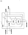
本発明に係る信号処理方法を実現する第1実施形態として、劣化信号(所望の信号と雑音とが混合された信号)から、雑音の一部又は全部を抑圧し、強調信号(所望の信号を強調した信号)を出力する雑音抑圧装置100について説明する。図1は、雑音抑圧装置100の全体構成を示すブロック図である。雑音抑圧装置100は、例えばデジタルカメラ、ノートパソコン、携帯電話などといった装置の一部としても機能するが、本発明はこれに限定されるものではなく、入力信号からのノイズ除去を要求されるあらゆる情報処理装置に適用可能である。
図1に示すように、雑音抑圧装置100は、入力端子1、変換部2、雑音抑圧部3、逆変換部4、出力端子5、分析部10、混合部11、雑音情報記憶部6を備えている。この雑音抑圧装置100は、大まかに言えば、入力した劣化信号を分析し、予め記憶された雑音情報を用いて、分析結果に応じた混合方法によって混合雑音情報(擬似雑音情報)を生成し、更に、その混合雑音情報を用いて雑音の抑圧を行なう。混合対象となる複数の雑音情報のうち少なくとも1つは予め雑音情報記憶部6に記憶されたものである。図19には、情報処理装置(雑音抑圧装置)100のブロック構成図の他の一例が示されている。情報処理装置100は、分析部10、混合部11、雑音抑圧部3を含む。以下では、図1を用いて説明する。
入力端子1には、劣化信号が、サンプル値系列として供給される。入力端子1に供給された劣化信号は、変換部2においてフーリエ変換などの変換を施されて複数の周波数成分に分割される。複数の周波数成分の振幅スペクトルは雑音抑圧部3へ供給され、位相スペクトルは、逆変換部4に伝達される。なお、ここでは、雑音抑圧部3に振幅スペクトルが供給されているが、本発明はこれに限定されるものではなく、その二乗に相当するパワースペクトルが雑音抑圧部3に供給されても良い。
雑音情報記憶部6は、半導体メモリなどの記憶素子を含み、抑圧対象としての既知の雑音の特性に関する情報(雑音情報)を記憶している。抑圧対象として記憶される既知の雑音は、例えば、シャッター音、モータ駆動音、ズーム音、オートフォーカスのフォーカシングノイズ(カチカチという音)等である。
一方、分析部10は、変換部2で生成された劣化信号振幅スペクトルを入力し、分析を行なう。分析部10は、劣化信号振幅スペクトルを分析することによって、劣化信号に含まれる雑音の特性を決定し、その特性に応じた雑音情報の混合方法を決定する。そして、分析部10は、決定した混合方法を混合部11に渡す。混合部11は、分析部10から受け取った混合方法に応じて、雑音情報記憶部6に記憶された雑音情報から混合雑音情報を生成する。
雑音抑圧部3は、変換部2から供給された劣化信号振幅スペクトルと混合部11から供給された混合雑音情報とを用いて、各周波数で雑音を抑圧し、雑音抑圧結果としての強調信号振幅スペクトルを逆変換部4に伝達する。逆変換部4は、雑音抑圧部3から供給された強調信号振幅スペクトルと変換部2から供給された劣化信号の位相スペクトルとを合わせて逆変換を行い、強調信号サンプルとして、出力端子5に供給する。
[変換部の構成]
図2は、変換部2の構成を示すブロック図である。図2に示すように、変換部2はフレーム分割部21、窓がけ処理部(windowing unit)22、及びフーリエ変換部23を含む。劣化信号サンプルは、フレーム分割部21に供給され、K/2サンプル毎のフレームに分割される。ここで、Kは偶数とする。フレームに分割された劣化信号サンプルは、窓がけ処理部22に供給され、窓関数(window function)であるw(t)との乗算が行なわれる。第nフレームの入力信号yn(t)(t=0,1,...,K/2−1)に対するw(t)で窓がけ(windowing)された信号は、次式(1)で与えられる。

以後、連続する2フレームの50%をオーバラップして窓がけする場合を例として説明を続ける。w(t)としては、例えば、次式(3)に示すハニング窓を用いることができる。
[逆変換部の構成]
図3は、逆変換部4の構成を示すブロック図である。図3に示すように、逆変換部4は逆フーリエ変換部43、窓がけ処理部42、及び、フレーム合成部41を含む。逆フーリエ変換部43は、雑音抑圧部3から供給された強調信号振幅スペクトルと変換部2から供給された劣化信号位相スペクトルarg Yn(k)とを乗算して、強調信号(以下の式(4)の左辺)を求める。
また、変換部2が周波数成分を複数統合してから、雑音抑圧部3が実際の抑圧を行うこともできる。その際、変換部2は聴覚特性の弁別能力が高い低周波領域から、能力が低い高周波領域に向かって、よりたくさんの周波数成分を統合することにより、高い音質を達成することができる。このように、雑音抑圧装置100は、複数の周波数成分を統合してから雑音抑圧を実行すると、雑音抑圧を適用する周波数成分の数が少なくなるため、全体の演算量を削減することができる。
[雑音抑圧部の処理]
雑音抑圧部3は、様々な抑圧を行うことが可能であるが、代表的なものとして、SS(Spectrum Subtraction:スペクトル減算)法とMMSE STSA(Minimum Mean−Square Error Short−Time Spectral Amplitude Estimator:最小二乗平均誤差短時間振幅スペクトル推定)法とがある。SS法は、混合部11から供給された混合雑音情報を、変換部2から供給された劣化信号振幅スペクトルから減算する。MMSE STSA法は、混合部11から供給された混合雑音情報と変換部2から供給された劣化信号振幅スペクトルを用いて、複数の周波数成分それぞれに対して抑圧係数を計算し、この抑圧係数を劣化信号振幅スペクトルに乗算する。この抑圧係数は、強調信号の平均二乗パワーを最小化するように決定される。
雑音抑圧部3における雑音の抑圧に際しては、過剰な抑圧を避けるために、フロアリングを適用することができる。フロアリングとは、最大抑圧量を超える抑圧を避ける方法である。フロアリングパラメータは最大抑圧量を決定する。SS法は、補正雑音情報を劣化信号振幅スペクトルから減算した結果が、フロアリングパラメータより小さくならないように制約をかける。具体的には、SS法は、減算結果がフロアリングパラメータよりも小さいときには、減算結果をフロアリングパラメータで置換する。また、MMSE STSA法は、補正雑音情報と劣化信号振幅スペクトルから求めた抑圧係数が、フロアリングパラメータよりも小さいときに、抑圧係数をフロアリングパラメータで置換する。フロアリングの詳細に関しては、文献「M.Berouti,R.Schwartz and J.Makhoul,″Enhancement of speech corrupted by acoustic noise,″Proceedings of ICASSP’79,pp.208−−211,Apr.1979」に開示されている。雑音抑圧部3は、フロアリングパラメータを導入することによって、過剰な抑圧を生じなくなる。フロアリングは、強調信号の歪が大きくなることを防止することができる。
雑音抑圧部3は、雑音情報の周波数成分数を劣化信号スペクトルの周波数成分数よりも小さく設定することもできる。このとき、複数の雑音情報が複数の周波数成分に対して共用されることになる。劣化信号スペクトルと雑音情報の双方に対して、複数の周波数成分を統合する場合と比べて、劣化信号スペクトルの周波数分解能が高いので、雑音抑圧部3は、周波数成分の統合が全くない場合よりも少ない演算量で、高い音質を達成することができる。劣化信号スペクトルの周波数成分数よりも少ない周波数成分数の雑音情報を用いた抑圧の詳細は、特開2008−203879号に開示されている。
[雑音情報記憶部の構成]
図4は、雑音情報記憶部6の内部構成を説明するための図である。図4では、雑音情報記憶部6に予め複数の雑音情報601〜60nが記憶されている。雑音情報601〜60nは、例えば、既知の雑音の最大雑音情報と平均雑音情報の組合せ、最大雑音情報と平均雑音情報と最小雑音情報の組合せ、ピーク成分雑音情報とそれ以外の組合せ、衝撃成分雑音情報とそれ以外の組合せ等である。雑音情報601〜60nは、分散やメジアンなどの統計量を含んでもよい。また、雑音情報記憶部6は、スペクトルに加えて、位相の周波数特性、特定の周波数における強弱や時間変化などの特徴量を記憶してもよい。
なお、平均雑音情報、最大雑音情報、最小雑音情報、ピーク成分雑音情報、衝撃成分雑音情報の定義は以下の通りである。
平均雑音情報:既知の雑音の全体(複数フレーム)についてフーリエ変換により導きだされる複数のスペクトルについて同じ周波数成分の振幅(またはパワー)を平均したもの。いわゆる時間方向に平均した平均スペクトル。
最大雑音情報:既知の雑音の全体(複数フレーム)についてフーリエ変換により導きだされる複数のスペクトルの周波数成分ごとの振幅(またはパワー)の最大値、いわゆる最大スペクトル。
最小雑音情報:既知の雑音の全体(複数フレーム)についてフーリエ変換により導きだされる複数のスペクトルの周波数成分ごとの振幅(またはパワー)の最小値、いわゆる最小スペクトル。
ピーク成分雑音情報:既知の雑音の全体(複数フレーム)についてフーリエ変換により導きだされるスペクトルにおいて、周波数方向に順に振幅を比較したときに、近傍の値に比べて突出して大きい値を有する周波数成分。
衝撃成分雑音情報:衝撃音の全体についてフーリエ変換により導きだされる複数のスペクトルの平均、いわゆる衝撃音の平均スペクトル。衝撃音自体は、フーリエ変換前の音声信号の時間変化を観測したときに、極めて短時間だけ大きな値を持つものであるが、フーリエ変換後のスペクトルは、所定の周波数帯域に渡って振幅がほぼ一定という特徴を有する。
以上の構成により、本実施形態によれば、変動の激しい信号特性に対応した雑音抑圧を実現することができる。特に、平均と最大とを混合対象の雑音情報とすれば、混合割合を変化させて、平均と最大の間の任意の値を合成でき、擬似ノイズの精度が高くなり、抑圧による音質が向上する。平均と最小、または最大と平均と最小とを混合対象の雑音情報とした場合にも同様の効果が生じる。
(第2実施形態)
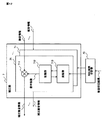
本発明の第2実施形態としての雑音抑圧装置について図5を用いて説明する。第1実施形態と比べた場合、本実施形態に係る雑音抑圧装置は、雑音情報記憶部61の内容及び混合部111の構成が異なるのみであり、他の構成は第1実施形態と同様であるため、ここでは同じ構成については同じ符号を付してその説明を省略する。
本実施形態では、雑音情報記憶部61は、平均雑音情報611のみを記憶している。そして、混合部111内の最大雑音情報生成部1112は、平均雑音情報611から最大雑音情報を生成する。混合制御部1111は、平均雑音情報と生成された最大雑音情報とを重み付けを行ないつつ混合する。
なお、本実施形態では最大雑音情報生成部1112が最大雑音情報を生成することとしたが、本発明はこれに限定されるものではなく、混合部111内で平均雑音情報から最小雑音情報が生成されてもよい。更には、雑音情報記憶部61に記憶されている雑音情報も平均雑音情報611に限定されず、最大雑音情報や最小雑音情報でもよい。
また、混合部111は、入力した雑音情報Nに対して、係数βを積算することにより最大雑音情報βNを生成し、それらを、分析部10の分析結果に応じた重み付けα1、α2で加算して、混合雑音情報M=α1N+α2βNを求めてもよい。この場合、混合雑音情報M=(α1+α2β)N=γNと変形できるため、結果的に、混合雑音情報Mは、入力した雑音情報Nに係数γを積算したものとなる。すなわち、分析部10による分析結果に応じて係数γが算出されれば(この過程が混合ステップと言える)、混合部111は、入力した雑音情報Nに係数γを積算する処理を行なうこととなる。記憶した雑音情報から2つ以上の雑音情報を生成する場合も同様である。
このような制御が行なれる場合には、最大雑音情報生成部1112は存在せず、混合制御部1111が、上記のM=(α1+α2β)N=γNに従って、分析部10から提供された情報に基づいて求めたα1とα2に従ってα1+α2βを計算し、その結果γと雑音情報記憶部61からの雑音情報Nを用いてγNを求める。すなわち、α1+α2βの計算が混合処理に相当する。この類似度の判定は、全周波数帯に渡ってスペクトル形状を比較する場合に限定されるものではなく、特徴的な一部の周波数帯同士を比較することにより、類似度が算出されてもよい。そのようにすれば、スペクトル形状の特徴が一部の周波数帯に限定される場合に、最終的な類似度検出の精度が上がるという効果が得られる。
本実施形態によれば、雑音情報記憶部61に記憶された雑音情報雑音情報から他の雑音情報を生成し、それらを混合することにより、雑音情報記憶部61の記憶容量を小さくしつつ変動の激しい信号特性に対応した雑音抑圧を実現することができる。
(第3実施形態)
本発明の第3実施形態としての雑音抑圧装置について図6を用いて説明する。第1実施形態と比べた場合、本実施形態に係る雑音抑圧装置は、分析部の内部構成及び雑音情報記憶部の内容が異なるのみであり、他の構成は第1実施形態と同様であるため、ここでは同じ構成については同じ符号を付してその説明を省略する。本実施形態では、抑圧対象となる雑音情報の基本成分と特殊成分とが予め別々に記憶されており、劣化信号から特殊成分が検出された場合に、記憶された特殊成分の値を用いて混合雑音情報が生成される。そして、本実施形態では特殊成分の一例としてピーク成分の記憶及び検出が行なわれる。
図6において、分析部101は、ピーク成分検出部1011を含む。ピーク成分検出部1011は、入力した劣化信号スペクトルから、ピークとなる周波数成分を検出する。例えば所定の閾値よりも振幅値が大きく、かつ周辺の周波数成分よりも振幅値が大きい周波数成分をピークと判断する。また、ピーク成分検出部1011は、例えば、隣接する周波数成分における振幅値との差分が所定の閾値以上の場合、ピーク成分と判定してもよい。ピーク成分検出部1011は、予め雑音のピークが表われる周波数成分が分かっている場合には、その周辺のみをピーク成分検出の対象としてもよい。
混合部11は、ピークと判定された周波数成分と、それ以外とで、異なる混合割合で、雑音情報を混合する。例えば、予め、雑音情報記憶部62に、抑圧対象となる雑音の最大スペクトルが雑音情報621として記憶され、平均スペクトルが雑音情報622として記憶されている。そして、ピーク成分検出により、何処にピークがあるのかが検出されると、混合部11は、その場所(周波数成分)によって雑音情報621からの最大値と雑音情報622からの平均値の混合比率を変えればよい。例えばピーク成分検出部1011は、全ての周波数成分(例えば1024)のそれぞれについて、独立にピーク検出を行ない、混合部11は、ピークがある周波数成分については、最大スペクトルの振幅を80%、平均スペクトルの振幅を20%混合してもよい。一方、混合部11は、ピーク以外の成分については、平均を100%使ってもよい。混合部11は、ピーク検出の精度(ピークがある尤もらしさ)に応じて、混合割合を変えてもよい。例えば、混合部11は、100%ピークと認められる周波数成分については、最大スペクトルでの振幅を100%としてもよい。
予め、雑音情報記憶部62に、抑圧対象となる雑音のピーク成分とそれ以外の成分とが分けて記憶されており、ピークと判定された周波数成分について、混合部11は記憶されたピーク成分を読出し、それ以外の周波数成分については、ピーク以外の成分を読出してもよい。例えば、ピーク成分検出部1011で検出した周波数成分が、雑音情報621として記憶されたピーク成分とずれていたとしても、そのずれ量(周波数のステップ数)が所定値以下の場合には、混合部11は、ピーク成分として記憶された振幅を用いて混合を行なう。
ピーク成分検出部1011の内部構成について図7を用いて説明する。図7に示すようにピーク成分検出部1011は、比較部10111、遅延部10112、閾値選択部10113を備えている。
過去(1つ前のフレームなど)にピークがあった周波数(例えば5番と20番)の周辺(4〜6番及び19〜21番)は、ピークが出やすい。ピーク成分検出部1011は、これを用いてピークの検出を行なう。ピーク成分検出部1011は、例えば、その周辺のみピーク検出の閾値を小さくすることでピークを検出されやすくする。
具体的には、比較部10111は、劣化信号中の振幅(またはパワー)を周波数成分ごとに閾値と比較する。そして、比較部10111は、ピークであると判断された周波数成分については、その情報を遅延部10112に保存しておく。そして、続くいくつかのフレームでは、ピークが検出された周波数の近傍において、閾値選択部10113が小さな閾値を選択して、比較部10111に渡す。これにより、一度ピークが発見された周波数成分の近傍においては、再度ピークとして検出されやすくなる。
また、閾値選択部10113は、雑音情報記憶部に記憶されているピーク成分の周波数を参照し、その周波数の近傍の周波数について、閾値を下げ、ピークを検出しやすくしてもよい。
本実施形態では、ピーク成分を独立して混合対象としている。ピークは局在するので、ピークに関しては、存在位置とその値だけが記憶されればよい。つまり、本実施形態によれば、存在可能性のあるすべての位置に対してメモリを準備する必要がないため、メモリ容量を削減できる。また、ピークを分離することで、ピークとそれ以外をあわせて記憶する場合よりもダイナミックレンジを狭くすることができる。これは、精度の改善またはビット数の削減に通じる。後者は、メモリ領域の削減に通じる。すなわち、コスト削減に有効である。
(第4実施形態)
本発明の第4実施形態としての雑音抑圧装置について図8を用いて説明する。本実施形態は、図4に示した混合部の内部構成の具体例について説明するものである。混合部以外の構成は第1実施形態と同様であるため、ここではその説明を省略する。
図8において、混合部112は、分析部10による分析結果に基づいて、雑音情報の混合割合α1〜αnを算出する混合割合算出部1131を備えている。
算出された混合割合α1〜αnはそれぞれ乗算部1121〜112nに渡され、それぞれの乗算部1121〜112nにおいて、雑音情報601〜60nと乗算される。つまり、劣化信号の分析の結果、雑音情報601を80%混合すべきという判断がなされた場合、混合割合算出部1131は、α1として0.8を出力する。そして、乗算部1121において、雑音情報601に対して0.8が乗算される。そのように係数を乗算された雑音情報は、加算部1132に入力され、加算される。これにより、混合雑音情報が生成される。
なお、本実施形態では例として雑音情報に係数を乗算して線形加算しているが、本発明はこれに限定されず、例えば、分析結果に応じた数式を用いて雑音情報を非線形に混合してもよい。
(第5実施形態)
本発明の第5実施形態としての雑音抑圧装置について図9を用いて説明する。本実施形態は、第1実施形態で示した混合部11の内部構成の他の例について説明するものである。検出部以外の構成は第1実施形態と同様であるため、ここでは同じ構成については同じ符号を付してその説明を省略する。
まず、本実施形態に係る分析部102には、類似度評価部1021が設けられている。ここでの抑圧対象は、特殊なスペクトル形状を有する特殊雑音情報である。類似度評価部1021は、雑音情報記憶部63に予め記憶された特殊雑音情報632と、入力した劣化信号スペクトルとの類似性を評価する。そして、その類似度に応じて重み付けて、特殊雑音情報632を混合する。
具体的には、類似度評価部1021は、衝撃音スペクトル(所定周波数幅に渡って一定の振幅を有する)を特殊雑音情報632として記憶しており、入力した劣化信号スペクトルと、衝撃音スペクトルとの形状の類似度を評価する。
類似度の評価について、類似度評価部1021は、2つのスペクトルの周波数成分値の差の二乗総和を取り、特殊雑音情報632のスペクトルの周波数成分値の2乗値の総和で正規化する。類似度評価部1021は、その値が閾値以内であれば類似していると判断する。また、類似度評価部1021は、2つのスペクトルの周波数成分値の積の二乗総和を、特殊雑音情報632のスペクトルの周波数成分値の2乗値の総和で正規化することもできる。
類似度の評価の対象となる雑音は衝撃音に限定されるものではなく、スペクトル形状に特徴を有する雑音であればどのようなものでもよい。また、類似度評価部1021は、スペクトルの概形を用いて類似度を求めてもよい。つまり、類似度評価部1021は、たとえば、1024の周波数成分の値を8個にまとめて、点数を減らして演算してもよい。
このようにして求めた衝撃音との類似度が80%であれば、衝撃音を80%、他の基準音を20%混合した混合雑音情報が生成される。
衝撃成分とそれ以外のノイズは、特性が著しく異なる。従って、一方から他方を変形により作り出すことができない。そこで本実施形態のように、衝撃成分が別に記憶されることで、それぞれの特性に忠実なデータが準備される。結果として、雑音抑圧装置は、高精度な擬似雑音情報を生成することができ、抑圧によって音質が向上するという効果が得られる。
(第6実施形態)
本発明の第6実施形態としての雑音抑圧装置600について図10を用いて説明する。第1実施形態と比べた場合、本実施形態に係る雑音抑圧装置600は、雑音情報記憶部6と混合部11との間に補正部7が設けられている点で異なる。他の構成は第1実施形態と同様であるため、ここでは同じ構成については同じ符号を付してその説明を省略する。
図10において、補正部7は、雑音抑圧部3から供給された雑音抑圧結果としての強調信号振幅スペクトルに基づいた倍率係数を乗算することにより雑音情報を補正し、補正雑音情報として混合部11に供給する。
[補正部の構成]
図11は、補正部7の内部構成を示すブロック図である。補正部7は、雑音情報記憶部6に記憶された雑音情報の数に応じて、複数の補正雑音情報生成部71〜7nを備えている。もちろん、図5に示したように、雑音情報が1つしか記憶されていない場合には、補正雑音情報生成部も1つのみ備えられていればよい。
各補正雑音情報生成部71〜7nは、乗算部711、記憶部712、及び更新部713を含む。補正部7に供給された雑音情報は、乗算部711に供給される。記憶部712には、雑音情報を補正する際に用いられる補正用情報としての倍率係数が記憶されている。乗算部711は、雑音情報と倍率係数の積を求め、補正雑音情報として出力する。
一方、更新部713には、雑音抑圧結果としての強調信号振幅スペクトルが供給される。更新部713は、記憶部712内の倍率係数を読出し、雑音抑圧結果を用いて倍率係数を変更し、変更後の新しい倍率係数を記憶部712に供給する。記憶部712は、新しい倍率係数を、それまで記憶していた古い倍率係数に代えて、新たに記憶する。
更新部713は、帰還(feedback)された雑音抑圧結果を用いて倍率係数を更新するときには、所望信号が入力されていないタイミングでの雑音抑圧結果が大きいほど(抑圧されずに残った雑音が大きいほど)補正雑音情報が大きくなるように、倍率係数を更新する。所望信号が入力されていないタイミングでの雑音抑圧結果が大きいということは、抑圧が不十分であることを示し、倍率係数を変更することによって補正雑音情報を大きくすることが望ましいからである。補正雑音情報が大きいときには、SS法では減算する値が大きくなるため、雑音抑圧結果は小さくなる。また、MMSE STSA法のような乗算型の抑圧では、抑圧係数の計算に用いる信号対雑音比の推定値が小さくなるため、小さな抑圧係数が得られる。これは、より強力な雑音抑圧をもたらす。倍率係数を更新する方法は、複数の方法が考えられる。例として、再計算法及び逐次更新法について説明する。
雑音抑圧結果としては、雑音が完全に抑圧された状態が理想である。このため、補正部7は、例えば、劣化信号の振幅又はパワーが小さいときに、雑音が完全に抑圧されるように、倍率係数を再計算又は逐次更新することができる。劣化信号の振幅又はパワーが小さいときには、抑圧しようとする雑音以外の信号のパワーも小さい確率が高いからである。補正部7は、劣化信号の振幅又はパワーが小さいことを、劣化信号の振幅又はパワーが閾値よりも小さいことを用いて検出できる。
また、補正部7は、劣化信号の振幅又はパワーが小さいことを、劣化信号の振幅又はパワーと雑音情報記憶部6に記録されている雑音情報との差分が、閾値より小さいことを用いても検出できる。すなわち、補正部7は、劣化信号の振幅又はパワーが雑音情報と似ているときに、劣化信号における雑音情報の占有率が高い(信号対雑音比が低い)ことを利用する。特に、補正部7は、複数の周波数点における情報を複合的に用いることにより、スペクトル概形を比較することが可能となり、検出精度を高くすることができる。
SS法における倍率係数は、各周波数において、補正雑音情報が、所望信号が入力されていないタイミングでの劣化信号スペクトルに等しくなるように、再計算される。言い換えれば、補正部7は、雑音だけを入力した時点で変換部2から供給された劣化信号振幅スペクトル|Yn(k)|と、倍率係数αnと雑音情報ν(k)との積が一致するように倍率係数αnを求める。ここでnはフレーム番号、kは、周波数番号である。すなわち、倍率係数αn(k)は次式(8)で計算される。
αn(k)=|Yn(k)|/νn(k) ・・・(8)
一方、SS法における倍率係数の逐次更新は、各周波数において、所望信号が入力されていないタイミングでの強調信号振幅スペクトルがゼロに近づくように、倍率係数を少しずつ更新する。補正部7は、逐次更新に最小二乗平均(Least Squares Method,LMS)アルゴリズムを用いる場合には、n番目フレーム、周波数番号kの誤差en(k)を用いて、αn+1(k)を次式(9)で計算する。
αn+1(k)=αn(k)+μen(k)/νn(k)・・・(9)
ただし、μはステップサイズと呼ばれる微小定数である。
補正部7は、計算して得られた倍率係数αn(k)を直ちに利用するときには、数式(9)の代わりに以下の数式(10)を用いる。
αn(k)=αn−1(k)+μen(k)/νn(k)・・・(10)
すなわち、補正部7は、現在の誤差を用いて現在の倍率係数αn(k)を計算し、直ちに適用する。補正部7は、倍率係数を直ちに更新することにより、リアルタイムで高精度の雑音抑圧を実現できる。
正規化最小二乗平均(NLMS)アルゴリズムを用いる場合には、上述の誤差en(k)を用いて、倍率係数αn+1(k)を次式(11)で計算する。
αn+1(k)=αn(k)+μen(k)νn(k)/σn(k)2・・・(11)
σn(k)2は、雑音情報νn(k)の平均パワーであり、FIRフィルタに基づく平均(スライド窓を用いた移動平均)やIIRフィルタに基づく平均(漏れ積分)などを用いて計算できる。
また、補正部7は、摂動法を用いて、以下の式(12)によって倍率係数αn+1(k)を計算しても良い。
αn+1(k)=αn(k)+μen(k)・・・(12)
また、補正部7は、誤差の符号だけ表わす符号関数sgn{en(k)}を用いて、以下の式(13)によって倍率係数αn+1(k)を計算しても良い。
αn+1(k)=αn(k)+μ・sgn{en(k)}・・・(13)
同様に、補正部7は、最小二乗アルゴリズム(Least Squares,LS)アルゴリズムやその他の適応アルゴリズムを用いてもよい。また、補正部7は、更新した倍率係数を直ちに適用することも可能であり、数式(9)から数式(10)への変更を参照して、数式(11)〜数式(13)を変形して、倍率係数をリアルタイム更新してもよい。
MMSE STSA法は、倍率係数を逐次更新する。補正部7は、各周波数において、数式(8)から数式(13)を用いて説明した方法と同様の方法で、倍率係数αn(k)を更新する。
上述した倍率係数の更新方法としての再計算法と逐次更新法について、再計算法は追従速度が速く、逐次更新法は精度が高いという特徴がある。これらの特徴を活かすために、補正部7は、最初は再計算法を用い、後に逐次更新法を用いる、というように更新方法を変更することも可能である。補正部7は、更新方法の変更のタイミングを決定するにあたり、倍率係数が最適値に十分近くなったこと条件とすることもできる。また、補正部7は、例えば、予め定められた時間が経過したときに更新方法を変更してもよい。またさらに、補正部7は、倍率係数の補正量が予め定められた閾値よりも小さくなったときに更新方法を変更することもできる。
本実施形態によれば、雑音抑圧に用いられる雑音情報を補正するにあたり、その補正に用いられる補正用情報を、雑音抑圧結果に基づいて更新するので、予め多数の雑音情報を記憶することなく、未知な雑音を含む多種多様な雑音を抑圧することができる。
なお、補正部7は、雑音抑圧結果に応じて、雑音情報の混合割合を補正してもよい。その場合、補正部7は、例えば図8に示した混合割合α1〜αnの値を補正することによって本実施形態と同様の効果を得ることができる。
(第7実施形態)
本発明の第7実施形態としての雑音抑圧装置について図12を用いて説明する。第6実施形態と比べた場合、本実施形態に係る雑音抑圧装置は、補正部7に抑圧結果分析部70が設けられている点で異なる。他の構成は第6実施形態と同様であるため、ここでは同じ構成については同じ符号を付してその説明を省略する。
抑圧結果分析部70は、抑圧結果を分析し、どの雑音情報について消し残り量が多いかに応じて倍率係数を修正する。これにより、補正部7は、複数の雑音情報において、消し残り量が多かった雑音情報について、比較的積極的に補正することができる。
(第8実施形態)
本発明の第8実施形態としての雑音抑圧装置について図13を用いて説明する。第6実施形態では、雑音信号を補正するための補正用情報として倍率係数を用いたが、本実施形態では、倍率係数にオフセットを加えた値を補正用情報とする。この場合は、倍率係数とオフセットとの両方が雑音抑圧結果に基づいて更新される。
図13は、補正部7の内部構成を示すブロック図である。補正部7は、雑音情報記憶部6に記憶された雑音情報の数に応じて、複数の補正雑音情報生成部71〜7nを備えている。もちろん、図5に示したように、雑音情報が1つしか記憶されていない場合には、補正雑音情報生成部も1つのみ備えられていればよい。
図13に示すように、各補正雑音情報生成部71〜7nは、図11で説明した構成に加えて、加算部714、記憶部715、及び更新部716を有している。乗算部711、記憶部712、及び更新部713の動作は図11を用いて説明した通りであるので、ここでは説明を省略する。
乗算部711は、入力された雑音情報と記憶部712から読出した倍率係数とを乗算し、その積を加算部714に供給する。加算部714は、記憶部715に記憶されているオフセット値を、乗算部711の出力から減算し、補正雑音情報として出力する。
一方、更新部716には、更新部713と同じ雑音抑圧結果が供給され、記憶部715に記憶されているオフセット値を、雑音抑圧結果を用いて更新し、新しいオフセット値を記憶部715に供給する。記憶部715は、新しいオフセット値を、それまで記憶していた古いオフセット値に代えて、新たに記憶する。
以上のように本実施形態では、雑音情報の補正に用いられる補正用情報として、倍率係数とオフセットとを用いたので、より一層細かく雑音情報を補正することができ、結果として、雑音抑圧効果を高めることができる。
(第9実施形態)
本発明の第9実施形態としての雑音抑圧装置について図14を用いて説明する。第8実施形態と比べた場合、本実施形態に係る雑音抑圧装置は、補正部7に抑圧結果分析部70が設けられている点で異なる。他の構成は第8実施形態と同様であるため、ここでは同じ構成については同じ符号を付してその説明を省略する。
抑圧結果分析部70では、抑圧結果を分析し、どの雑音情報について消し残り量が多いかに応じて倍率係数及びオフセットを修正する。これにより、補正部7は、複数の雑音情報において、消し残り量が多かった雑音情報について、比較的積極的に補正することができる。
(第10実施形態)
本発明の第10実施形態について、図15を用いて説明する。第10実施形態としての雑音抑圧装置1500に含まれる雑音抑圧部3には、入力端子9から、入力した劣化信号中に特定の雑音が存在するか否かを示す情報(雑音存在情報)が供給される。これにより、特定の雑音が存在しているタイミングで、確実に雑音を抑圧することができる。その他の構成及び動作については第1実施形態と同様であるためここでは詳細な説明を省略する。
(第11実施形態)
本発明の第11実施形態について、図16を用いて説明する。第1実施形態としての雑音抑圧装置1600に含まれる雑音抑圧部3及び補正部7には、入力端子9から、入力した劣化信号中に特定の雑音が存在するか否かを示す情報(雑音存在情報)が供給される。これにより、特定の雑音が存在しているタイミングで、確実に雑音を抑圧し、同時に、補正用情報の更新を行なうことができる。その他の構成及び動作については第1実施形態と同様であるためここでは詳細な説明を省略する。また、本実施形態によれば、特定の雑音が存在していないタイミングでは、補正用情報の更新を行なわないので、特定の雑音に対する雑音抑圧の精度を向上させることができる。
(第12実施形態)
本発明の第12実施形態について、図17を用いて説明する。本実施形態における雑音抑圧装置1200は、所望信号存在判定部81を有している。所望信号存在判定部81には、変換部2からの劣化信号振幅スペクトルが伝達される。所望信号存在判定部81は、劣化信号振幅スペクトルを解析し、所望信号が存在するか否か、或いは、どの程度存在するのかを判定する。
補正部87は、所望信号存在判定部81での判定結果に基づいて、雑音情報を補正するための補正用情報を更新する。例えば、所望信号がないときには、劣化信号は全て雑音から構成されるので、雑音抑圧部3での抑圧結果はゼロになるはずである。したがって、補正部87は、この時の雑音抑圧結果がゼロになるように、倍率係数などを調整する。
一方、劣化信号に所望信号が含まれている場合には、所望信号の存在割合に応じて、補正部87における補正用情報の更新が行なわれる。例えば、劣化信号中に所望信号が10%存在している場合には、部分的に(90%だけ)補正用情報が更新される。
本実施形態によれば、劣化信号中の雑音の割合に応じて補正情報を更新するので、結果的により精度の高い雑音抑圧結果を得ることができる。
(他の実施形態)
以上説明してきた第1乃至第12実施形態は、それぞれ別々の特徴を持つ雑音抑圧装置について説明したが、それらの特徴を如何様に組み合わせた雑音抑圧装置も、本発明の範疇に含まれる。
また、本発明は、複数の機器から構成されるシステムに適用しても良いし、単体の装置に適用しても良い。さらに、本発明は、実施形態の機能を実現するソフトウェアの信号処理プログラムが、システム或いは装置に直接或いは遠隔から供給される場合にも適用可能である。したがって、本発明の機能をコンピュータで実現するために、コンピュータにインストールされるプログラム、或いはそのプログラムを格納した媒体、そのプログラムをダウンロードさせるWWWサーバも、本発明の範疇に含まれる。
図18は、第1実施形態を信号処理プログラムにより構成した場合に、その信号処理プログラムを実行するコンピュータ1800の構成図である。コンピュータ1800は、入力部1801と、CPU1802と、雑音情報記憶部1803と、出力部1804と、メモリ1805と、通信制御部1806とを含む。
CPU1802は、メモリ1805に格納された信号処理プログラムを読み込むことにより、コンピュータ1800全体の動作を制御する。すなわち、信号処理プログラムを実行したCPU1802は、劣化信号を分析して混合方法を決定する(S1821)。次に、CPU1802は、決定した混合方法で複数の雑音情報を混合して混合雑音情報を生成する(S1822)。混合対象となる複数の雑音情報のうち少なくとも1つは予め雑音情報記憶部1803に記憶されたものである。つぎに、CPU1802は、混合雑音情報を用いて劣化信号中の雑音を抑圧し(S1823)、処理を終了する。
これにより、第1実施形態と同様の効果を得ることができる。
[実施形態の他の表現]
上記の実施形態の一部又は全部は、以下の付記のようにも記載されうるが、以下には限られない。
(付記1)
劣化信号中の雑音を抑圧するため、
入力した劣化信号を分析し、
抑圧対象となる雑音に関する雑音情報を、前記劣化信号の分析結果に応じて混合して混合雑音情報を生成し、
前記混合雑音情報を用いて前記雑音の抑圧を行なうことを特徴とする信号処理方法。
(付記2)
予め記憶された前記雑音情報から、前記混合雑音情報を生成するために混合される混合対象の雑音情報を生成することを特徴とする付記1に記載の信号処理方法。
(付記3)
抑圧対象となる雑音の平均スペクトル及び最大スペクトルを前記雑音情報として混合して前記混合雑音情報を生成することを特徴とする付記1または2に記載の信号処理方法。
(付記4)
抑圧対象となる雑音の平均スペクトル、最大スペクトル及び最小スペクトルを前記雑音情報として混合して前記混合雑音情報を生成することを特徴とする付記1または2に記載の信号処理方法。
(付記5)
抑圧対象となる雑音に関する平均スペクトルを予め記憶しておき、
前記最大スペクトルを前記平均スペクトルから生成することを特徴とする付記3または4に記載の信号処理方法。
(付記6)
抑圧対象となる雑音に関する平均スペクトルを予め記憶しておき、
前記最小スペクトルを前記平均スペクトルから生成することを特徴とする付記4に記載の信号処理方法。
(付記7)
前記劣化信号を分析して特殊成分を検出した場合に、
抑圧対象となる雑音の周波数成分のうち、前記特殊成分及びそれ以外の基本成分を、それぞれ前記雑音情報として混合して前記混合雑音情報を生成することを特徴とする付記1乃至6の何れかに記載の信号処理方法。
(付記8)
前記劣化信号を分析してピーク成分を検出した場合に、
抑圧対象となる雑音の周波数成分のうち、前記ピーク成分及びそれ以外の基本成分を、それぞれ前記雑音情報として混合して前記混合雑音情報を生成することを特徴とする付記1乃至6の何れかに記載の信号処理方法。
(付記9)
混合対象となる複数の雑音情報のそれぞれに対して、前記劣化信号の分析に応じた係数を乗算してから加算することにより前記混合雑音情報を生成するを特徴とする付記1乃至8の何れかに記載の信号処理方法。
(付記10)
特殊なスペクトル形状を有する特殊雑音情報を予め記憶しておき、
前記劣化信号の分析により、前記特殊雑音情報と入力した劣化信号との類似度を評価し、
前記類似度が高い場合には、前記特殊雑音情報を混合して前記混合雑音情報を生成することを特徴とする付記1乃至9のいずれか1項に記載の信号処理方法。
(付記11)
前記特殊雑音情報は、衝撃音の雑音情報であることを特徴とする付記10に記載の信号処理方法。
(付記12)
雑音抑圧結果に基づいて前記雑音情報を補正することを特徴とする付記1乃至11の何れかに記載の信号処理方法。
(付記13)
雑音抑圧結果に応じた倍率係数を乗算することにより前記雑音情報を補正することを特徴とする付記12に記載の信号処理方法。
(付記14)
雑音抑圧結果に応じてオフセットすることにより前記雑音情報を補正することを特徴とする付記12または13に記載の信号処理方法。
(付記15)
雑音抑圧結果を分析した結果に基づいて、混合対象となる複数の前記雑音情報をそれぞれ補正することを特徴とする付記12乃至14の何れかに記載の信号処理方法。
(付記16)
劣化信号中に雑音が存在するか否かを示す情報を入力し、
劣化信号中に雑音が存在している場合に、前記雑音の抑圧を行なうことを特徴とする付記1乃至15の何れかに記載の信号処理方法。
(付記17)
前記劣化信号を解析して、前記劣化信号中に所望信号がどの程度存在しているかを判定し、その判定結果に基づいて、前記雑音の抑圧を行なうことを特徴とする付記1乃至16の何れかに記載の信号処理方法。
(付記18)
入力した劣化信号を分析する分析手段と、
抑圧対象となる雑音に関する雑音情報を、前記劣化信号の分析結果に応じて混合して混合雑音情報を生成する混合手段と、
前記混合雑音情報を用いて前記雑音の抑圧を行なう雑音抑圧手段と、
を備えたことを特徴とする情報処理装置。
(付記19)
入力した劣化信号を分析する分析工程と、
抑圧対象となる雑音に関する雑音情報を、前記劣化信号の分析結果に応じて混合して混合雑音情報を生成する混合工程と、
前記混合雑音情報を用いて前記雑音の抑圧を行なう雑音抑圧工程と、
をコンピュータに実行させることを特徴とする信号処理プログラム。
以上、実施形態を参照して本願発明を説明したが、本願発明は上記実施形態に限定されるものではない。本願発明の構成や詳細には、本願発明のスコープ内で当業者が理解しうる様々な変更をすることができる。
この出願は、2010年5月24日に出願された日本出願特願2010−118842を基礎とする優先権を主張し、その開示の全てをここに取り込む。Hereinafter, exemplary embodiments of the present invention will be described in detail with reference to the drawings. However, the components described in the following embodiments are merely examples, and are not intended to limit the technical scope of the present invention only to them.
(First embodiment)
[overall structure]
As a first embodiment for realizing the signal processing method according to the present invention, a part or all of noise is suppressed from a deteriorated signal (a signal in which a desired signal and noise are mixed), and an enhanced signal (a desired signal is changed). A
As shown in FIG. 1, the
A degradation signal is supplied to the input terminal 1 as a sample value series. The degraded signal supplied to the input terminal 1 is subjected to transformation such as Fourier transformation in the transformation unit 2 and is divided into a plurality of frequency components. The amplitude spectra of the plurality of frequency components are supplied to the
The noise
On the other hand, the
The
[Configuration of conversion unit]
FIG. 2 is a block diagram illustrating a configuration of the conversion unit 2. As shown in FIG. 2, the converting unit 2 includes a
Hereinafter, the description will be continued by taking as an example a case in which 50% of two consecutive frames overlap each other. As w (t), for example, a Hanning window represented by the following equation (3) can be used.
[Configuration of inverse transform unit]
FIG. 3 is a block diagram showing the configuration of the inverse transform unit 4. As shown in FIG. 3, the inverse transform unit 4 includes an inverse
Further, after the conversion unit 2 integrates a plurality of frequency components, the
[Processing of noise suppression unit]
The
When noise is suppressed in the
The
[Configuration of noise information storage unit]
FIG. 4 is a diagram for explaining the internal configuration of the noise
The definitions of average noise information, maximum noise information, minimum noise information, peak component noise information, and impact component noise information are as follows.
Average noise information: averaged amplitude (or power) of the same frequency component for a plurality of spectra derived by Fourier transform for the entire known noise (multiple frames). An average spectrum averaged in the time direction.
Maximum noise information: a maximum value of amplitude (or power) for each frequency component of a plurality of spectra derived by Fourier transform for the entire known noise (a plurality of frames), so-called maximum spectrum.
Minimum noise information: the minimum value of the amplitude (or power) for each frequency component of a plurality of spectra derived by Fourier transform for the entire known noise (a plurality of frames), so-called minimum spectrum.
Peak component noise information: A frequency component that has a large value prominently compared to neighboring values when comparing amplitudes in order in the frequency direction in the spectrum derived by Fourier transform for the entire known noise (multiple frames). .
Impact component noise information: The average of a plurality of spectra derived by Fourier transform for the entire impact sound, so-called average spectrum of impact sound. The impact sound itself has a large value for a very short time when the time change of the audio signal before the Fourier transform is observed, but the spectrum after the Fourier transform has almost the same amplitude over a predetermined frequency band. It has the characteristic of being constant.
With the above configuration, according to the present embodiment, it is possible to realize noise suppression corresponding to signal characteristics that fluctuate drastically. In particular, if the average and maximum are used as noise information to be mixed, it is possible to synthesize any value between the average and maximum by changing the mixing ratio, increasing the accuracy of pseudo-noise and improving the sound quality due to suppression. . The same effect can be obtained when the average and minimum, or the maximum and average and minimum are used as noise information to be mixed.
(Second Embodiment)
A noise suppression apparatus as a second embodiment of the present invention will be described with reference to FIG. Compared with the first embodiment, the noise suppression device according to the present embodiment is different only in the content of the noise
In the present embodiment, the noise
In the present embodiment, the maximum noise
Further, the
When such control can be performed, the maximum noise
According to the present embodiment, other noise information is generated from the noise information stored in the noise
(Third embodiment)
A noise suppression apparatus as a third embodiment of the present invention will be described with reference to FIG. Compared to the first embodiment, the noise suppression device according to the present embodiment is different only in the internal configuration of the analysis unit and the content of the noise information storage unit, and the other configurations are the same as in the first embodiment. Here, the same components are denoted by the same reference numerals, and the description thereof is omitted. In this embodiment, the basic component and special component of noise information to be suppressed are stored separately in advance, and when the special component is detected from the degradation signal, mixing is performed using the stored special component value. Noise information is generated. In this embodiment, the peak component is stored and detected as an example of the special component.
In FIG. 6, the
The mixing
The noise peak component of noise to be suppressed and the other components are stored separately in the noise
The internal configuration of the peak
Peaks are likely to appear in the vicinity (numbers 4-6 and 19-21) of frequencies (for example,
Specifically, the
Further, the
In the present embodiment, the peak components are independently mixed. Since the peak is localized, only the existing position and its value need be stored for the peak. That is, according to the present embodiment, it is not necessary to prepare a memory for every position where there is a possibility of being present, so that the memory capacity can be reduced. Further, by separating the peaks, the dynamic range can be narrowed compared to the case of storing the peaks and the others together. This leads to an improvement in accuracy or a reduction in the number of bits. The latter leads to a reduction in memory area. That is, it is effective for cost reduction.
(Fourth embodiment)
A noise suppression apparatus as a fourth embodiment of the present invention will be described with reference to FIG. In the present embodiment, a specific example of the internal configuration of the mixing unit illustrated in FIG. 4 will be described. Since the configuration other than the mixing unit is the same as that of the first embodiment, the description thereof is omitted here.
In FIG. 8, the
The calculated mixing ratios α1 to αn are respectively passed to the
In the present embodiment, noise information is multiplied by a coefficient and linearly added as an example, but the present invention is not limited to this, and for example, noise information is mixed non-linearly using an equation according to the analysis result. May be.
(Fifth embodiment)
A noise suppression apparatus as a fifth embodiment of the present invention will be described with reference to FIG. In the present embodiment, another example of the internal configuration of the mixing
First, a
Specifically, the
For the similarity evaluation, the
The noise to be evaluated for similarity is not limited to the impact sound, and any noise having a characteristic in the spectrum shape may be used. Further, the
If the degree of similarity with the impact sound thus obtained is 80%, mixed noise information in which the impact sound is 80% and the other reference sounds are mixed by 20% is generated.
The impact component and other noises have significantly different characteristics. Therefore, one cannot be created from the other by deformation. Therefore, as in the present embodiment, the impact component is stored separately, so that data faithful to each characteristic is prepared. As a result, the noise suppression device can generate highly accurate pseudo-noise information, and an effect that the sound quality is improved by the suppression can be obtained.
(Sixth embodiment)
A
In FIG. 10, the
[Configuration of correction unit]
FIG. 11 is a block diagram showing the internal configuration of the
Each of the corrected noise
On the other hand, the updating
When the
As a result of noise suppression, a state where noise is completely suppressed is ideal. For this reason, the correction |
Further, the
The magnification factor in the SS method is recalculated so that the corrected noise information is equal to the deteriorated signal spectrum at the timing when the desired signal is not input at each frequency. In other words, the
αn (k) = | Yn (k) | / νn (k) (8)
On the other hand, the sequential update of the magnification coefficient in the SS method updates the magnification coefficient little by little so that the emphasized signal amplitude spectrum at the timing at which the desired signal is not input approaches zero at each frequency. When the least square mean (LMS) algorithm is used for the sequential update, the
αn + 1 (k) = αn (k) + μen (k) / νn (k) (9)
However, μ is a minute constant called a step size.
The
αn (k) = αn−1 (k) + μen (k) / νn (k) (10)
That is, the
When using the normalized least mean square (NLMS) algorithm, the magnification coefficient αn + 1 (k) is calculated by the following equation (11) using the error en (k) described above.
αn + 1 (k) = αn (k) + μen (k) νn (k) / σn (k) 2 (11)
σn (k) 2 Is the average power of the noise information νn (k) and can be calculated using an average based on the FIR filter (moving average using a sliding window), an average based on the IIR filter (leakage integration), and the like.
Further, the
αn + 1 (k) = αn (k) + μen (k) (12)
Further, the
αn + 1 (k) = αn (k) + μ · sgn {en (k)} (13)
Similarly, the
The MMSE STSA method sequentially updates the magnification factor. The
Regarding the recalculation method and the sequential update method as the magnification coefficient update method described above, the recalculation method has a feature that the follow-up speed is fast and the sequential update method has high accuracy. In order to make use of these features, the
According to the present embodiment, when correcting the noise information used for noise suppression, the correction information used for the correction is updated based on the noise suppression result, so without storing a large amount of noise information in advance. A wide variety of noises including unknown noises can be suppressed.
The
(Seventh embodiment)
A noise suppression apparatus as a seventh embodiment of the present invention will be described with reference to FIG. Compared to the sixth embodiment, the noise suppression device according to the present embodiment is different in that a suppression
The suppression
(Eighth embodiment)
A noise suppression apparatus as an eighth embodiment of the present invention will be described with reference to FIG. In the sixth embodiment, the magnification coefficient is used as the correction information for correcting the noise signal. In this embodiment, a value obtained by adding an offset to the magnification coefficient is used as the correction information. In this case, both the magnification coefficient and the offset are updated based on the noise suppression result.
FIG. 13 is a block diagram illustrating an internal configuration of the
As illustrated in FIG. 13, each of the corrected noise
The
On the other hand, the
As described above, in the present embodiment, since the magnification coefficient and the offset are used as the correction information used for correcting the noise information, the noise information can be corrected more finely. As a result, the noise suppression effect can be obtained. Can be increased.
(Ninth embodiment)
A noise suppression apparatus as a ninth embodiment of the present invention will be described with reference to FIG. Compared to the eighth embodiment, the noise suppression device according to the present embodiment is different in that a suppression
The suppression
(10th Embodiment)
A tenth embodiment of the present invention will be described with reference to FIG. Information (noise presence information) indicating whether or not specific noise exists in the input degraded signal is supplied from the
(Eleventh embodiment)
An eleventh embodiment of the present invention will be described with reference to FIG. The
(Twelfth embodiment)
A twelfth embodiment of the present invention will be described with reference to FIG. The
The
On the other hand, when the desired signal is included in the deteriorated signal, the correction information is updated in the
According to the present embodiment, the correction information is updated according to the ratio of noise in the degraded signal, and as a result, a more accurate noise suppression result can be obtained.
(Other embodiments)
In the first to twelfth embodiments described above, noise suppression devices having different characteristics have been described. However, noise suppression devices that combine these features in any way are also included in the scope of the present invention.
Further, the present invention may be applied to a system composed of a plurality of devices, or may be applied to a single device. Furthermore, the present invention is also applicable to a case where a software signal processing program that implements the functions of the embodiments is supplied directly or remotely to a system or apparatus. Therefore, in order to realize the functions of the present invention on a computer, a program installed in the computer, a medium storing the program, and a WWW server that downloads the program are also included in the scope of the present invention.
FIG. 18 is a configuration diagram of a
The
Thereby, the effect similar to 1st Embodiment can be acquired.
[Other expressions of embodiment]
A part or all of the above-described embodiment can be described as in the following supplementary notes, but is not limited thereto.
(Appendix 1)
To suppress noise in the degraded signal,
Analyzing the input degradation signal,
Noise information related to noise to be suppressed is mixed according to the analysis result of the deteriorated signal to generate mixed noise information,
A signal processing method, wherein the noise is suppressed using the mixed noise information.
(Appendix 2)
The signal processing method according to appendix 1, wherein noise information to be mixed is generated from the noise information stored in advance to be mixed to generate the mixed noise information.
(Appendix 3)
The signal processing method according to appendix 1 or 2, wherein the mixed noise information is generated by mixing an average spectrum and a maximum spectrum of noise to be suppressed as the noise information.
(Appendix 4)
The signal processing method according to appendix 1 or 2, wherein the mixed noise information is generated by mixing an average spectrum, a maximum spectrum, and a minimum spectrum of noise to be suppressed as the noise information.
(Appendix 5)
An average spectrum related to the noise to be suppressed is stored in advance,
The signal processing method according to
(Appendix 6)
An average spectrum related to the noise to be suppressed is stored in advance,
The signal processing method according to appendix 4, wherein the minimum spectrum is generated from the average spectrum.
(Appendix 7)
When a special component is detected by analyzing the deterioration signal,
Any one of appendices 1 to 6, wherein among the frequency components of noise to be suppressed, the special component and other basic components are mixed as the noise information to generate the mixed noise information. The signal processing method as described.
(Appendix 8)
When analyzing the deterioration signal and detecting a peak component,
Any one of Supplementary notes 1 to 6, wherein, among the frequency components of noise to be suppressed, the peak component and other basic components are mixed as the noise information to generate the mixed noise information. The signal processing method as described.
(Appendix 9)
Any one of appendices 1 to 8, wherein the mixed noise information is generated by multiplying each of a plurality of noise information to be mixed by a coefficient corresponding to the analysis of the deteriorated signal and adding the coefficients. A signal processing method according to claim 1.
(Appendix 10)
Pre-store special noise information with a special spectral shape,
By analyzing the deterioration signal, the similarity between the special noise information and the input deterioration signal is evaluated,
The signal processing method according to any one of supplementary notes 1 to 9, wherein when the similarity is high, the mixed noise information is generated by mixing the special noise information.
(Appendix 11)
The signal processing method according to
(Appendix 12)
12. The signal processing method according to any one of appendices 1 to 11, wherein the noise information is corrected based on a noise suppression result.
(Appendix 13)
13. The signal processing method according to
(Appendix 14)
14. The signal processing method according to
(Appendix 15)
15. The signal processing method according to any one of
(Appendix 16)
Enter information indicating whether noise is present in the degraded signal,
16. The signal processing method according to any one of appendices 1 to 15, wherein the noise is suppressed when noise is present in the degraded signal.
(Appendix 17)
Any one of appendices 1 to 16, wherein the deterioration signal is analyzed to determine how much a desired signal is present in the deterioration signal, and the noise is suppressed based on the determination result. A signal processing method according to claim 1.
(Appendix 18)
An analysis means for analyzing the input deterioration signal;
Mixing means for mixing noise information related to noise to be suppressed according to the analysis result of the deteriorated signal to generate mixed noise information;
Noise suppression means for suppressing the noise using the mixed noise information;
An information processing apparatus comprising:
(Appendix 19)
An analysis process for analyzing the input degradation signal;
A mixing step of generating noise information by mixing noise information related to noise to be suppressed according to the analysis result of the deterioration signal;
A noise suppression step of suppressing the noise using the mixed noise information;
A signal processing program for causing a computer to execute.
While the present invention has been described with reference to the embodiments, the present invention is not limited to the above embodiments. Various changes that can be understood by those skilled in the art can be made to the configuration and details of the present invention within the scope of the present invention.
This application claims the priority on the basis of Japanese application Japanese Patent Application No. 2010-118842 for which it applied on May 24, 2010, and takes in those the indications of all here.
Claims (19)
前記変換信号を分析して分析結果を生成し、
予め記憶された抑圧対象となる雑音に関する複数の雑音情報を、前記分析結果に応じて混合して混合雑音情報を生成し、
前記混合雑音情報と前記変換信号を用いて前記雑音の抑圧を行なう信号処理方法。 Convert the input degraded signal to generate a converted signal,
Analyzing the converted signal to generate an analysis result;
A plurality of noise information related to noise to be suppressed stored in advance is mixed according to the analysis result to generate mixed noise information,
A signal processing method for suppressing the noise using the mixed noise information and the converted signal.
前記最大スペクトルを前記平均スペクトルから生成する請求項3または4に記載の信号処理方法。 An average spectrum related to the noise to be suppressed is stored in advance,
The signal processing method according to claim 3, wherein the maximum spectrum is generated from the average spectrum.
前記最小スペクトルを前記平均スペクトルから生成する請求項4に記載の信号処理方法。 An average spectrum related to the noise to be suppressed is stored in advance,
The signal processing method according to claim 4, wherein the minimum spectrum is generated from the average spectrum.
抑圧対象となる雑音の周波数成分のうち、前記特殊成分及びそれ以外の基本成分を、それぞれ前記雑音情報として混合して前記混合雑音情報を生成する請求項1乃至6の何れか1項に記載の信号処理方法。 When a special component is detected by analyzing the deterioration signal,
The mixed noise information according to any one of claims 1 to 6, wherein among the frequency components of noise to be suppressed, the special component and other basic components are mixed as the noise information, respectively, to generate the mixed noise information. Signal processing method.
抑圧対象となる雑音の周波数成分のうち、前記ピーク成分及びそれ以外の基本成分を、
それぞれ前記雑音情報として混合して前記混合雑音情報を生成する請求項1乃至6の何れか1項に記載の信号処理方法。 When analyzing the deterioration signal and detecting a peak component,
Among the frequency components of noise to be suppressed, the peak component and other basic components are
The signal processing method according to claim 1, wherein the mixed noise information is generated by mixing as the noise information.
前記劣化信号の分析により、前記特殊雑音情報と入力した劣化信号との類似度を評価し、
前記類似度が高い場合には、前記特殊雑音情報を混合して前記混合雑音情報を生成する請求項1乃至9のいずれか1項に記載の信号処理方法。 Pre-store special noise information with a special spectral shape,
By analyzing the deterioration signal, the similarity between the special noise information and the input deterioration signal is evaluated,
The signal processing method according to claim 1, wherein when the similarity is high, the mixed noise information is generated by mixing the special noise information.
劣化信号中に雑音が存在している場合に、前記雑音の抑圧を行なう請求項1乃至15の何れか1項に記載の信号処理方法。 Enter information indicating whether noise is present in the degraded signal,
The signal processing method according to claim 1, wherein the noise is suppressed when noise is present in the degraded signal.
前記変換信号を分析して分析結果を生成する分析手段と、
予め記憶された抑圧対象となる雑音に関する複数の雑音情報を、前記分析結果に応じて混合して混合雑音情報を生成する混合手段と、
前記混合雑音情報と前記変換信号を用いて前記雑音の抑圧を行なう雑音抑圧手段と、
を備える情報処理装置。 Conversion means for converting the input deterioration signal to generate a conversion signal;
Analyzing means for analyzing the converted signal and generating an analysis result;
Mixing means for generating a mixed noise information by mixing a plurality of noise information relating to noise to be suppressed stored in advance according to the analysis result;
Noise suppression means for suppressing the noise using the mixed noise information and the converted signal;
An information processing apparatus comprising:
前記変換信号を分析して分析結果を生成し、
予め記憶された抑圧対象となる雑音に関する複数の雑音情報を、前記分析結果に応じて混合して混合雑音情報を生成し、
前記混合雑音情報と前記変換信号を用いて前記雑音の抑圧を行なうこと、
をコンピュータに実行させる信号処理プログラム。 Convert the input degraded signal to generate a converted signal,
Analyzing the converted signal to generate an analysis result;
A plurality of noise information related to noise to be suppressed stored in advance is mixed according to the analysis result to generate mixed noise information,
Performing the noise suppression using the mixed noise information and the converted signal;
A signal processing program for causing a computer to execute.
Priority Applications (1)
| Application Number | Priority Date | Filing Date | Title |
|---|---|---|---|
| JP2012517234A JP5867389B2 (en) | 2010-05-24 | 2011-05-13 | Signal processing method, information processing apparatus, and signal processing program |
Applications Claiming Priority (4)
| Application Number | Priority Date | Filing Date | Title |
|---|---|---|---|
| JP2010118842 | 2010-05-24 | ||
| JP2010118842 | 2010-05-24 | ||
| PCT/JP2011/061597 WO2011148860A1 (en) | 2010-05-24 | 2011-05-13 | Signal processing method, information processing device, and signal processing program |
| JP2012517234A JP5867389B2 (en) | 2010-05-24 | 2011-05-13 | Signal processing method, information processing apparatus, and signal processing program |
Publications (2)
| Publication Number | Publication Date |
|---|---|
| JPWO2011148860A1 JPWO2011148860A1 (en) | 2013-07-25 |
| JP5867389B2 true JP5867389B2 (en) | 2016-02-24 |
Family
ID=45003850
Family Applications (1)
| Application Number | Title | Priority Date | Filing Date |
|---|---|---|---|
| JP2012517234A Active JP5867389B2 (en) | 2010-05-24 | 2011-05-13 | Signal processing method, information processing apparatus, and signal processing program |
Country Status (5)
| Country | Link |
|---|---|
| US (1) | US9837097B2 (en) |
| EP (1) | EP2579254B1 (en) |
| JP (1) | JP5867389B2 (en) |
| CN (1) | CN102906813A (en) |
| WO (1) | WO2011148860A1 (en) |
Families Citing this family (13)
| Publication number | Priority date | Publication date | Assignee | Title |
|---|---|---|---|---|
| US9763003B2 (en) * | 2011-01-12 | 2017-09-12 | Staten Techiya, LLC | Automotive constant signal-to-noise ratio system for enhanced situation awareness |
| JP5768450B2 (en) * | 2011-03-31 | 2015-08-26 | 富士通株式会社 | Noise estimation device and noise estimation program |
| EP2958038A1 (en) * | 2013-02-15 | 2015-12-23 | NEC Solution Innovators, Ltd. | Selection device for candidate sequence information for similarity determination, selection method, and use for such device and method |
| CA2949024C (en) | 2014-05-19 | 2018-07-17 | Nec Corporation | Sonar device, signal processing method, and recording medium |
| US10149047B2 (en) * | 2014-06-18 | 2018-12-04 | Cirrus Logic Inc. | Multi-aural MMSE analysis techniques for clarifying audio signals |
| US10746838B2 (en) | 2014-11-10 | 2020-08-18 | Nec Corporation | Signal processing apparatus, signal processing method, and signal processing program |
| JP6541179B2 (en) * | 2015-04-02 | 2019-07-10 | 日本電気株式会社 | Signal processor |
| KR20170051856A (en) * | 2015-11-02 | 2017-05-12 | 주식회사 아이티매직 | Method for extracting diagnostic signal from sound signal, and apparatus using the same |
| US11296739B2 (en) * | 2016-12-22 | 2022-04-05 | Nuvoton Technology Corporation Japan | Noise suppression device, noise suppression method, and reception device and reception method using same |
| TWI646842B (en) * | 2017-09-11 | 2019-01-01 | 晨星半導體股份有限公司 | Circuit applied to display device and related signal processing method |
| JP2019192963A (en) * | 2018-04-18 | 2019-10-31 | オリンパス株式会社 | Noise reduction device, noise reduction method and program |
| KR102327441B1 (en) * | 2019-09-20 | 2021-11-17 | 엘지전자 주식회사 | Artificial device |
| CN111294066B (en) * | 2020-01-16 | 2022-04-12 | Oppo广东移动通信有限公司 | Signal processing method, receiver and computer storage medium |
Citations (6)
| Publication number | Priority date | Publication date | Assignee | Title |
|---|---|---|---|---|
| JPH09258768A (en) * | 1996-03-25 | 1997-10-03 | Mitsubishi Electric Corp | Under-noise voice recognizing device and under-noise voice recognizing method |
| JP2002258897A (en) * | 2001-02-27 | 2002-09-11 | Fujitsu Ltd | Device for suppressing noise |
| JP2002314637A (en) * | 2001-04-09 | 2002-10-25 | Denso Corp | Device for reducing noise |
| JP2003284181A (en) * | 2002-03-20 | 2003-10-03 | Matsushita Electric Ind Co Ltd | Sound collection apparatus |
| JP2006262241A (en) * | 2005-03-18 | 2006-09-28 | Casio Comput Co Ltd | Electronic camera, noise reduction device, and noise reduction control program |
| JP2009282536A (en) * | 2003-05-30 | 2009-12-03 | National Institute Of Advanced Industrial & Technology | Method and device for removing known acoustic signal |
Family Cites Families (22)
| Publication number | Priority date | Publication date | Assignee | Title |
|---|---|---|---|---|
| JP3451146B2 (en) | 1995-02-17 | 2003-09-29 | 株式会社日立製作所 | Denoising system and method using spectral subtraction |
| JPH11514453A (en) * | 1995-09-14 | 1999-12-07 | エリクソン インコーポレイテッド | A system for adaptively filtering audio signals to enhance speech intelligibility in noisy environmental conditions |
| EP0973151B8 (en) * | 1998-07-16 | 2009-02-25 | Panasonic Corporation | Noise control system |
| US6519559B1 (en) | 1999-07-29 | 2003-02-11 | Intel Corporation | Apparatus and method for the enhancement of signals |
| JP3454206B2 (en) * | 1999-11-10 | 2003-10-06 | 三菱電機株式会社 | Noise suppression device and noise suppression method |
| US20030179888A1 (en) | 2002-03-05 | 2003-09-25 | Burnett Gregory C. | Voice activity detection (VAD) devices and methods for use with noise suppression systems |
| JP4282227B2 (en) | 2000-12-28 | 2009-06-17 | 日本電気株式会社 | Noise removal method and apparatus |
| JP2002236497A (en) * | 2001-02-08 | 2002-08-23 | Alpine Electronics Inc | Noise reduction system |
| JP3457293B2 (en) * | 2001-06-06 | 2003-10-14 | 三菱電機株式会社 | Noise suppression device and noise suppression method |
| US7224810B2 (en) * | 2003-09-12 | 2007-05-29 | Spatializer Audio Laboratories, Inc. | Noise reduction system |
| JP2006279185A (en) | 2005-03-28 | 2006-10-12 | Casio Comput Co Ltd | Imaging apparatus, and sound recording method and program |
| JP4765461B2 (en) * | 2005-07-27 | 2011-09-07 | 日本電気株式会社 | Noise suppression system, method and program |
| EP2555190B1 (en) | 2005-09-02 | 2014-07-02 | NEC Corporation | Method, apparatus and computer program for suppressing noise |
| JP4245617B2 (en) * | 2006-04-06 | 2009-03-25 | 株式会社東芝 | Feature amount correction apparatus, feature amount correction method, and feature amount correction program |
| JP4316583B2 (en) * | 2006-04-07 | 2009-08-19 | 株式会社東芝 | Feature amount correction apparatus, feature amount correction method, and feature amount correction program |
| WO2008129885A1 (en) * | 2007-04-13 | 2008-10-30 | Panasonic Corporation | Output control circuit and imaging device |
| US8189766B1 (en) * | 2007-07-26 | 2012-05-29 | Audience, Inc. | System and method for blind subband acoustic echo cancellation postfiltering |
| KR101444100B1 (en) * | 2007-11-15 | 2014-09-26 | 삼성전자주식회사 | Noise cancelling method and apparatus from the mixed sound |
| ATE552690T1 (en) | 2008-09-19 | 2012-04-15 | Dolby Lab Licensing Corp | UPSTREAM SIGNAL PROCESSING FOR CLIENT DEVICES IN A WIRELESS SMALL CELL NETWORK |
| JP5068240B2 (en) | 2008-11-12 | 2012-11-07 | 日本電信電話株式会社 | Optical transmission system, transmitter and receiver |
| US8798992B2 (en) * | 2010-05-19 | 2014-08-05 | Disney Enterprises, Inc. | Audio noise modification for event broadcasting |
| WO2011148861A1 (en) | 2010-05-25 | 2011-12-01 | 日本電気株式会社 | Signal processing method, information processing device, and signal processing program |
-
2011
- 2011-05-13 CN CN2011800255734A patent/CN102906813A/en active Pending
- 2011-05-13 WO PCT/JP2011/061597 patent/WO2011148860A1/en active Application Filing
- 2011-05-13 US US13/698,345 patent/US9837097B2/en active Active
- 2011-05-13 EP EP11786559.2A patent/EP2579254B1/en active Active
- 2011-05-13 JP JP2012517234A patent/JP5867389B2/en active Active
Patent Citations (6)
| Publication number | Priority date | Publication date | Assignee | Title |
|---|---|---|---|---|
| JPH09258768A (en) * | 1996-03-25 | 1997-10-03 | Mitsubishi Electric Corp | Under-noise voice recognizing device and under-noise voice recognizing method |
| JP2002258897A (en) * | 2001-02-27 | 2002-09-11 | Fujitsu Ltd | Device for suppressing noise |
| JP2002314637A (en) * | 2001-04-09 | 2002-10-25 | Denso Corp | Device for reducing noise |
| JP2003284181A (en) * | 2002-03-20 | 2003-10-03 | Matsushita Electric Ind Co Ltd | Sound collection apparatus |
| JP2009282536A (en) * | 2003-05-30 | 2009-12-03 | National Institute Of Advanced Industrial & Technology | Method and device for removing known acoustic signal |
| JP2006262241A (en) * | 2005-03-18 | 2006-09-28 | Casio Comput Co Ltd | Electronic camera, noise reduction device, and noise reduction control program |
Non-Patent Citations (1)
| Title |
|---|
| JPN6015027785; Kazuhiro Nakadai: 'Ego Noise Suppression of a Robot Using Template Subtraction' The 2009 IEEE/RSJ International Conference on Intelligent Robots and Systems October 11-15, 2009 St. , 20091015, 199〜204 * |
Also Published As
| Publication number | Publication date |
|---|---|
| US9837097B2 (en) | 2017-12-05 |
| CN102906813A (en) | 2013-01-30 |
| US20130064392A1 (en) | 2013-03-14 |
| EP2579254A4 (en) | 2014-07-02 |
| EP2579254B1 (en) | 2017-07-12 |
| EP2579254A1 (en) | 2013-04-10 |
| JPWO2011148860A1 (en) | 2013-07-25 |
| WO2011148860A1 (en) | 2011-12-01 |
Similar Documents
| Publication | Publication Date | Title |
|---|---|---|
| JP5867389B2 (en) | Signal processing method, information processing apparatus, and signal processing program | |
| JP5788873B2 (en) | Signal processing method, information processing apparatus, and signal processing program | |
| JP5310494B2 (en) | Signal processing method, information processing apparatus, and signal processing program | |
| US20090296958A1 (en) | Noise suppression method, device, and program | |
| JP6064600B2 (en) | Signal processing apparatus, signal processing method, and signal processing program | |
| WO2012070670A1 (en) | Signal processing device, signal processing method, and signal processing program | |
| JP6300031B2 (en) | Signal processing apparatus, signal processing method, and signal processing program | |
| JP5294085B2 (en) | Information processing apparatus, accessory apparatus thereof, information processing system, control method thereof, and control program | |
| JP5787126B2 (en) | Signal processing method, information processing apparatus, and signal processing program | |
| JP6182862B2 (en) | Signal processing apparatus, signal processing method, and signal processing program | |
| WO2011055829A1 (en) | Signal processing method, information processor, and signal processing program | |
| JP6011536B2 (en) | Signal processing apparatus, signal processing method, and computer program | |
| US10109291B2 (en) | Noise suppression device, noise suppression method, and computer program product | |
| JP6119604B2 (en) | Signal processing apparatus, signal processing method, and signal processing program |
Legal Events
| Date | Code | Title | Description |
|---|---|---|---|
| A621 | Written request for application examination |
Free format text: JAPANESE INTERMEDIATE CODE: A621 Effective date: 20140417 |
|
| A131 | Notification of reasons for refusal |
Free format text: JAPANESE INTERMEDIATE CODE: A131 Effective date: 20141007 |
|
| A521 | Request for written amendment filed |
Free format text: JAPANESE INTERMEDIATE CODE: A523 Effective date: 20141205 |
|
| A131 | Notification of reasons for refusal |
Free format text: JAPANESE INTERMEDIATE CODE: A131 Effective date: 20150714 |
|
| A521 | Request for written amendment filed |
Free format text: JAPANESE INTERMEDIATE CODE: A523 Effective date: 20150910 |
|
| TRDD | Decision of grant or rejection written | ||
| A01 | Written decision to grant a patent or to grant a registration (utility model) |
Free format text: JAPANESE INTERMEDIATE CODE: A01 Effective date: 20151208 |
|
| A61 | First payment of annual fees (during grant procedure) |
Free format text: JAPANESE INTERMEDIATE CODE: A61 Effective date: 20151221 |
|
| R150 | Certificate of patent or registration of utility model |
Ref document number: 5867389 Country of ref document: JP Free format text: JAPANESE INTERMEDIATE CODE: R150 |