JP5867040B2 - Electrostatic actuator, electrostatic actuator control method, and stator - Google Patents
Electrostatic actuator, electrostatic actuator control method, and stator Download PDFInfo
- Publication number
- JP5867040B2 JP5867040B2 JP2011270052A JP2011270052A JP5867040B2 JP 5867040 B2 JP5867040 B2 JP 5867040B2 JP 2011270052 A JP2011270052 A JP 2011270052A JP 2011270052 A JP2011270052 A JP 2011270052A JP 5867040 B2 JP5867040 B2 JP 5867040B2
- Authority
- JP
- Japan
- Prior art keywords
- main operation
- detection
- electrode
- linear electrode
- electrostatic actuator
- Prior art date
- Legal status (The legal status is an assumption and is not a legal conclusion. Google has not performed a legal analysis and makes no representation as to the accuracy of the status listed.)
- Expired - Fee Related
Links
Images


Landscapes
- Micromachines (AREA)
Description
本発明は、静電アクチュエータ、静電アクチュエータの制御方法、および固定子に関する。 The present invention relates to an electrostatic actuator, an electrostatic actuator control method, and a stator.
従来、電極が設けられた固定子と、フィルムなどの抵抗体が設けられた移動子と、を有する静電アクチュエータがある。このような、静電アクチュエータには、複数相の信号で駆動する方式が採用される。 2. Description of the Related Art Conventionally, there is an electrostatic actuator having a stator provided with electrodes and a mover provided with a resistor such as a film. Such an electrostatic actuator employs a method of driving with signals of a plurality of phases.
ここで、このような静電アクチュエータにおいて、固定子上で移動子を直線運動させる場合に、摩擦抵抗の面内バラつきや異物により、移動子が蛇行したり、左右へ偏って移動したりする問題がある。 Here, in such an electrostatic actuator, when the slider is linearly moved on the stator, the slider may meander or move to the left and right due to in-plane variations in frictional resistance or foreign matter. There is.
このような問題に対して、従来の静電アクチュエータには、この移動子の蛇行や左右への偏りを防ぐためガイドを設ける技術がある。しかし、ガイドと移動子の間の摩擦抵抗により移動子の動作が阻害され、また、ガイドと移動子の摩擦により、不要な帯電が発生し得る。さらに、ガイドの位置で規制されるだけで、移動子を中央に戻す力は働かない。 In order to solve such a problem, the conventional electrostatic actuator has a technique of providing a guide for preventing the moving member from meandering and biasing to the left and right. However, the movement of the moving element is hindered by the frictional resistance between the guide and the moving element, and unnecessary charging may occur due to the friction between the guide and the moving element. Furthermore, the force to return the moving element to the center does not work only by being regulated by the position of the guide.
そこで、従来の静電アクチュエータには、電圧供給ラインが移動子の移動方向に沿って電極の両側に設けられたものがある(例えば、特許文献1参照。)。これにより、移動子の進行方向に垂直なモーメント成分は、電極の両側の2本の電圧供給ラインの静電気力により固定される。したがって、移動子の回転モーメントの発生が抑制され、移動子の蛇行が防止される。 Therefore, there is a conventional electrostatic actuator in which voltage supply lines are provided on both sides of the electrode along the moving direction of the moving element (see, for example, Patent Document 1). Thereby, the moment component perpendicular to the moving direction of the moving element is fixed by the electrostatic force of the two voltage supply lines on both sides of the electrode. Therefore, the generation of the rotational moment of the mover is suppressed, and the meandering of the mover is prevented.
ここで、上記従来の静電アクチュエータには、光センサを用いて移動子の位置を検出するものがある。しかし、このような光センサは、外光、特に赤外光の影響を受けると、所定の検出ができない問題がある。さらに、固定子の表面には、光センサのための穴を設ける必要があり、この穴には、異物が混入する可能性があり、また、この穴のために意匠性が低くなる問題がある。 Here, some of the conventional electrostatic actuators detect the position of the moving element using an optical sensor. However, such an optical sensor has a problem that predetermined detection cannot be performed when it is affected by outside light, particularly infrared light. Furthermore, it is necessary to provide a hole for the optical sensor on the surface of the stator. There is a possibility that foreign matter may be mixed in the hole, and there is a problem that the design property is lowered due to the hole. .
本発明は、外光の影響を受けることなく、移動子の位置を検出することが可能な静電アクチュエータを提供する。 The present invention provides an electrostatic actuator capable of detecting the position of a moving element without being affected by external light.
本発明の一態様に係る静電アクチュエータは、
固定子と、
前記固定子上に配置された移動子と、
前記固定子に信号を出力して前記移動子の動作を制御する制御装置と、を備え、
前記固定子は、
一面と他面とを有する基板と、
前記基板の一面に各々独立して設けられ、互いに平行に等間隔で配置された複数の主動作用線状電極と、
前記基板の一面に設けられ、前記複数の主動作用線状電極に直交する方向で前記複数の主動作用線状電極に隣接し且つ前記複数の主動作用線状電極に対して平行に配置された検出用線状電極と、
前記基板の一面に設けられ、前記複数の主動作用線状電極との間に前記検出用線状電極が位置するように前記検出用線状電極と平行に配置され且つグランドに電気的に接続されたグランド電極と、を有し、
前記制御装置は、
帯電した前記移動子と前記検出用線状電極との間の距離が変化することによる前記検出用線状電極と前記グランド電極との間の電位差の変化に対応する検出信号に基づいて、前記移動子の位置を検出する
ことを特徴とする静電アクチュエータである。
An electrostatic actuator according to an aspect of the present invention is provided.
A stator,
A mover disposed on the stator;
A control device that outputs a signal to the stator to control the operation of the movable element,
The stator is
A substrate having one side and the other side;
A plurality of main operation linear electrodes provided independently on one surface of the substrate and arranged in parallel to each other at equal intervals;
Detection provided on one surface of the substrate, adjacent to the plurality of main operation linear electrodes in a direction orthogonal to the plurality of main operation linear electrodes, and arranged in parallel to the plurality of main operation linear electrodes. A linear electrode;
Provided on one surface of the substrate, arranged in parallel with the detection linear electrode and electrically connected to the ground so that the detection linear electrode is positioned between the plurality of main operation linear electrodes. And a ground electrode,
The controller is
The movement based on a detection signal corresponding to a change in potential difference between the detection linear electrode and the ground electrode due to a change in the distance between the charged movable element and the detection linear electrode. It is an electrostatic actuator characterized by detecting the position of a child.
また、上記静電アクチュエータにおいて、
前記制御装置は、
前記固定子の前記主動作用線状電極に印加する信号が変化しないタイミングにおいて、前記電位差に応じた電位差信号を取得する演算回路を有してもよい。
In the electrostatic actuator,
The controller is
You may have an arithmetic circuit which acquires the electric potential difference signal according to the said electric potential difference in the timing which the signal applied to the said linear electrode for main operation | movement of the said stator does not change.
また、上記静電アクチュエータにおいて、
前記演算回路は、
前記電位差に応じた電位差信号のパターンを認識し、前記電位差信号に含まれるパルス波を除去することにより、前記電位差信号に含まれる前記検出信号を抽出してもよい。
In the electrostatic actuator,
The arithmetic circuit is:
The detection signal included in the potential difference signal may be extracted by recognizing a pattern of the potential difference signal corresponding to the potential difference and removing a pulse wave included in the potential difference signal.
また、上記静電アクチュエータにおいて、
前記制御装置は、
前記電位差信号をアナログ・デジタル変換するアナログ・デジタル変換器をさらに有するようにしてもよい。
In the electrostatic actuator,
The controller is
An analog / digital converter that performs analog / digital conversion on the potential difference signal may be further included.
また、上記静電アクチュエータにおいて、
前記制御装置は、
前記電位差信号をフィルタリングするローパスフィルタを備えてもよい。
In the electrostatic actuator,
The controller is
A low-pass filter for filtering the potential difference signal may be provided.
また、上記静電アクチュエータにおいて、
前記制御装置は、
前記検出信号に基づいて、前記移動子が前記検出用線状電極に近接した状態であると判断してもよい。
In the electrostatic actuator,
The controller is
Based on the detection signal, it may be determined that the movable element is in a state of being close to the detection linear electrode.
また、上記静電アクチュエータにおいて、
前記制御装置は、
前記検出信号を連続して複数回検出した場合に、前記移動子が前記検出用線状電極に近接した状態であると判断してもよい。
In the electrostatic actuator,
The controller is
When the detection signal is detected a plurality of times in succession, it may be determined that the movable element is in a state of being close to the detection linear electrode.
また、上記静電アクチュエータにおいて、
前記制御装置は、
前記検出信号を検出した場合には、前記移動子の駆動を止める、または、前記移動子を逆方向に駆動させてもよい。
In the electrostatic actuator,
The controller is
When the detection signal is detected, driving of the moving element may be stopped, or the moving element may be driven in the reverse direction.
また、上記静電アクチュエータにおいて、
前記制御装置は、
前記検出信号を検出した場合には、前記移動子を所定期間そのまま駆動した後、前記移動子の駆動を止める、または前記移動子を逆方向に駆動させてもよい。
In the electrostatic actuator,
The controller is
When the detection signal is detected, the moving element may be driven as it is for a predetermined period, and then the driving of the moving element may be stopped or the moving element may be driven in the reverse direction.
また、上記静電アクチュエータにおいて、
前記検出用線状電極の幅は、前記主動作用線状電極の幅よりも太くてもよい。
In the electrostatic actuator,
The width of the detection linear electrode may be larger than the width of the main operation linear electrode.
また、上記静電アクチュエータにおいて、
前記検出用線状電極の幅は、前記主動作用線状電極の幅の3倍であってもよい。
In the electrostatic actuator,
The width of the detection linear electrode may be three times the width of the main operation linear electrode.
また、上記静電アクチュエータにおいて、
前記検出用線状電極に接続された配線と前記グランド電極に接続された配線とは、グランドに電気的に接続された2本の保護用グランド配線間に位置していてもよい。
In the electrostatic actuator,
The wiring connected to the detection linear electrode and the wiring connected to the ground electrode may be positioned between two protective ground wirings electrically connected to the ground.
また、上記静電アクチュエータにおいて、
前記複数の主動作用線状電極に含まれる4本の主動作用線状電極のうち、第1番目の主動作用線状電極と第3番目の主動作用線状電極へ、各々位相が反転した矩形波信号が入力され、
第2番目の主動作用線状電極と第4番目の主動作用線状電極へ、各々位相が反転した矩形波信号が入力され、
隣接する2つの電極に入力される2つの信号は、4分の1周期だけずれて同一強度を有してもよい。
In the electrostatic actuator,
Of the four main operation linear electrodes included in the plurality of main operation linear electrodes, a rectangular wave whose phase is inverted to the first main operation linear electrode and the third main operation linear electrode, respectively. Signal is input,
A rectangular wave signal whose phase is inverted is input to the second main operation linear electrode and the fourth main operation linear electrode,
Two signals input to two adjacent electrodes may have the same intensity by being shifted by a quarter period.
本発明の一態様に係る静電アクチュエータの制御方法は、
固定子と、前記固定子上に配置された移動子と、を備え、前記固定子は、一面と他面とを有する基板と、前記基板の一面に各々独立して設けられ、互いに平行に等間隔で配置された複数の主動作用線状電極と、前記基板の一面に設けられ、前記複数の主動作用線状電極に直交する方向で前記複数の主動作用線状電極に隣接し且つ前記複数の主動作用線状電極に対して平行に配置された検出用線状電極と、前記基板の一面に設けられ、前記複数の主動作用線状電極との間に前記検出用線状電極が位置するように前記検出用線状電極と平行に配置され且つグランドに電気的に接続されたグランド電極と、を有する静電アクチュエータの制御方法であって、
帯電した前記移動子と前記検出用線状電極との間の距離が変化することによる前記検出用線状電極と前記グランド電極との間の電位差の変化に対応する検出信号に基づいて、前記移動子の位置を検出する
ことを特徴とする静電アクチュエータの制御方法である。
An electrostatic actuator control method according to an aspect of the present invention includes:
A stator and a mover disposed on the stator, and the stator is provided on one surface of the substrate independently of the substrate having one surface and the other surface, and is parallel to each other. A plurality of main operation linear electrodes arranged at intervals, provided on one surface of the substrate, adjacent to the plurality of main operation linear electrodes in a direction perpendicular to the plurality of main operation linear electrodes, and the plurality of The detection linear electrode is disposed between the detection linear electrode arranged in parallel to the main operation linear electrode and the plurality of main operation linear electrodes provided on one surface of the substrate. And a ground electrode arranged in parallel to the detection linear electrode and electrically connected to the ground,
The movement based on a detection signal corresponding to a change in potential difference between the detection linear electrode and the ground electrode due to a change in the distance between the charged movable element and the detection linear electrode. An electrostatic actuator control method is characterized in that the position of a child is detected.
本発明の一態様に係る固定子は、
一面と他面とを有する基板と、
前記基板の一面に各々独立して設けられ、互いに平行に等間隔で配置された複数の主動作用線状電極と、
前記基板の一面に設けられ、前記複数の主動作用線状電極に直交する方向で前記複数の主動作用線状電極に隣接し且つ前記複数の主動作用線状電極に対して平行に配置された検出用線状電極と、
前記基板の一面に設けられ、前記複数の主動作用線状電極との間に前記検出用線状電極が位置するように前記検出用線状電極と平行に配置され且つグランドに電気的に接続されたグランド電極と、を有する
ことを特徴とする固定子である。
The stator according to one aspect of the present invention is:
A substrate having one side and the other side;
A plurality of main operation linear electrodes provided independently on one surface of the substrate and arranged in parallel to each other at equal intervals;
Detection provided on one surface of the substrate, adjacent to the plurality of main operation linear electrodes in a direction orthogonal to the plurality of main operation linear electrodes, and arranged in parallel to the plurality of main operation linear electrodes. A linear electrode;
Provided on one surface of the substrate, arranged in parallel with the detection linear electrode and electrically connected to the ground so that the detection linear electrode is positioned between the plurality of main operation linear electrodes. And a ground electrode.
本発明に係る静電アクチュエータによれば、外光の影響を受けることなく、移動子の位置を検出することができる。 According to the electrostatic actuator according to the present invention, the position of the moving element can be detected without being affected by external light.
以下、本発明による静電アクチュエータの実施の形態について図面に基づいて説明する。 Embodiments of an electrostatic actuator according to the present invention will be described below with reference to the drawings.
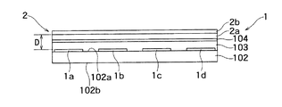
図1は、本発明による静電アクチュエータ100の構成の一例を示す斜視図である。また、図2は、図1に示す静電アクチュエータ100を模式的に示す上面図である。また、図3は、図2のA−A線に沿った静電アクチュエータ100の断面を示す断面図である。また、図4は、図2のB−B線に沿った静電アクチュエータ100の断面を示す断面図である。なお、簡単のため、図1においては、制御装置を省略している。また、図2おいては、カバーフィルム103、摺動構造膜104を省略している。
FIG. 1 is a perspective view showing an example of the configuration of an
図1および図2に示すように、静電アクチュエータ100は、固定子1と、移動子2と、制御装置CONと、を備える。
As shown in FIGS. 1 and 2, the
固定子1は、一面102aと他面102bとを有する基板102と、基板102の一面102aに各々独立して設けられ、互いに平行に等間隔で配置された少なくとも4本の主動作用線状電極1a〜1dと、基板102の一面102aに各々独立して設けられ、互いに平行に等間隔で配置された複数の補助動作用線状電極1s〜1vと、基板102の一面に設けられ、複数の主動作用線状電極1a〜1dに直交する方向で複数の主動作用線状電極1a〜1dに隣接し且つ複数の主動作用線状電極1a〜1dに対して平行に配置された検出用線状電極D1、D2と、基板102の一面に設けられ、複数の主動作用線状電極1a〜1dとの間に前記検出用線状電極G1、G2が位置するように検出用線状電極G1、G2と平行に配置され且つグランドに電気的に接続されたグランド電極G1、G2と、を有する。
The
移動子2は、この固定子1上に移動自在に配置されている。
The
制御装置CONは、固定子1に信号a〜d、s〜vを出力して移動子2の動作を制御するようになっている。また、制御装置CONは、電圧信号SD1、SD2、SG1、SG2に基づいて、移動子2の位置を検出し、この検出結果に応じて移動子2の動作を決定するようになっている。
The control device CON outputs signals a to d and s to v to the
なお、以下では、主動作用線状電極1a〜1dの一側(図2の下側)で主動作用線状電極1a〜1dに直交する方向に延在する補助動作用線状電極1s〜1vを、一側補助動作用線状電極と称し、主動作用線状電極1a〜1dの他側(図2の上側)で主動作用線状電極1a〜1dに直交する方向に延在する補助動作用線状電極1s〜1vを、他側補助動作用線状電極と称する場合がある。
In the following description, auxiliary operation
以下、固定子1について更に詳述する。上述のように、固定子1は、基板102と、基板102の一面102aに設けられた導電性を有する少なくとも4本の主動作用線状電極1a〜1dと、基板102の一面102aに設けられた導電性を有する複数の補助動作用線状電極1s〜1vと、を備えている。
Hereinafter, the
ここで、4本の主動作用線状電極1a〜1dのうち、第1番目の主動作用線状電極1aと第3番目の主動作用線状電極1cへ、各々位相が反転した矩形波信号または正弦波信号が入力され、第2番目の主動作用線状電極1bと第4番目の主動作用線状電極1dへ、各々位相が反転した矩形波信号または正弦波信号が入力される。
Here, out of the four main operation
また、隣接する2つの電極、例えば、第1番目の主動作用線状電極1aと第2番目の主動作用線状電極1bに入力される2つの信号は、4分の1周期だけずれて同一強度を有している。
In addition, two signals input to two adjacent electrodes, for example, the first main operation
さらに、4本の主動作用線状電極1a〜1dの一側に(図2の下側)、4本の主動作用線状電極1a〜1dに直交する方向に延設するとともに、第1番目の主動作用線状電極1aと第2番目の主動作用線状電極1bに各々接続される第1の主動作用バスライン101aと第2の主動作用バスライン101bが互いに平行に設けられている。
Further, the main operation
さらに、4本の主動作用線状電極1a〜1dの他側に(図2の上側)、4本の主動作用線状電極1a〜1dに直交する方向に延設するとともに第3番目の主動作用線状電極1cと第4番目の主動作用線状電極1dに各々接続される第3の主動作用バスライン1cと第4の主動作用バスライン1dとが互いに平行に設けられている。
Further, on the other side of the four main operation
また、上述のように、4本の主動作用線状電極1a〜1dの一側(図2の下側)に、4本の主動作用線状電極1a〜1dに直交する方向に延在する複数本(ここでは4本単位の組が2組で計8本)の一側補助動作用線状電極1s〜1vが設けられている。
In addition, as described above, a plurality of main operation
さらに、上述のように、4本の主動作用線状電極1a〜1dの他側(図2の上側)に、4本の主動作用線状電極に直交する方向に延在する複数本(ここでは4本単位の組が2組で計8本)の他側補助動作用線状電極1s〜1vが設けられている。
Further, as described above, a plurality (in this case,) extending in the direction orthogonal to the four main operation linear electrodes on the other side (upper side in FIG. 2) of the four main operation
そして、複数本の一側補助動作用線状電極1s〜1vと複数本の他側補助動作用線状電極1s〜1vとは、4本の主動作用線状電極の両側で、4本の主動作用線状電極1a〜1dを中心に対称に配置(本実施例では8本ずつ同じ配線ルールで配置)されている。
The plurality of one-side auxiliary operation
なお、複数本の一側補助動作用線状電極1s〜1vは、複数本の他側補助動作用線状電極1s〜1vよりも、本数が多く設けられていてもよい。これにより、例えば、静電アクチュエータ100を壁に固定した場合等、移動子2が固定子1の中央から離れる方向に力(重力)が印加される場合に、この力の向きと反対向き(この場合、補助動作方向Z)に補助力がより働くようにすることができる。
The plurality of one-side auxiliary operation
また、補助動作用線状電極1s〜1vが主動作用線状電極1a〜1dの両側に設けられていることにより、補助動作用線状電極1s〜1vを移動子2の位置補正目的だけでなく、主動作方向Xに直交する補助動作方向Y,Zを積極的に利用して、移動子2を主動作方向Xに対してジグザグに動かすようにすることもできる。
Further, since the auxiliary operation
また、4本の一側補助動作用線状電極1s〜1vのうち、第1番目の一側補助動作用線状電極1sと第3番目の一側補助動作用線状電極1uへ、各々位相が反転した矩形波信号または正弦波信号が入力され、第2番目の一側補助動作用線状電極1tと第4番目の一側補助動作用線状電極1vへ、各々位相が反転した矩形波信号または正弦波信号が入力される。
Of the four one-side auxiliary operation
そして、隣接する2つの一側補助動作用線状電極、例えば、第1番目の一側補助動作用線状電極1sと第2番目の一側補助動作用線状電極1tに入力される2つの信号は、4分の1周期だけずれて同一強度を有する。
Then, two adjacent one-side auxiliary operation linear electrodes, for example, two input to the first one-side auxiliary operation
すなわち、複数本の一側補助動作用線状電極1s〜1vへ互いに異なる位相の矩形波信号または正弦波信号が入力され、複数本の一側補助動作用線状電極1s〜1vに近接する移動子2を4本の主動作用線状電極1a〜1d側(補助動作方向Z)に移動させるようになっている。
That is, a rectangular wave signal or a sine wave signal having different phases is input to the plurality of one-side auxiliary operation
また、4本の他側補助動作用線状電極1s〜1vのうち、第1番目の他側補助動作用線状電極1sと第3番目の他側補助動作用線状電極1uへ、各々位相が反転した矩形波信号または正弦波信号が入力され、第2番目の他側補助動作用線状電極1tと第4番目の他側補助動作用線状電極1vへ、各々位相が反転した矩形波信号または正弦波信号が入力される。
Among the four other side auxiliary operation
そして、隣接する2つの他側補助動作用線状電極、例えば、第1番目の他側補助動作用線状電極1sと第2番目の他側補助動作用線状電極1tに入力される2つの信号は、4分の1周期だけずれて同一強度を有する。
Then, two adjacent auxiliary operation linear electrodes, for example, two input to the first other auxiliary operation
すなわち、複数本の他側補助動作用線状電極1s〜1vへ互いに異なる位相の矩形波信号または正弦波信号が入力され、複数本の他側補助動作用線状電極1s〜1vに近接する移動子2を4本の主動作用線状電極1a〜1d側(補助動作方向Y)に移動させるようになっている。
That is, rectangular wave signals or sine wave signals having different phases are input to the plurality of other side auxiliary operation
また、図2に示すように、第1番目の補助動作用線状電極1sと第2番目の補助動作用線状電極1tに各々接続される第1の補助動作用バスライン101sと第2の補助動作用バスライン101tが互いに平行に設けられている。
Further, as shown in FIG. 2, the first auxiliary
さらに、第3番目の補助動作用線状電極1uと第4番目の補助動作用線状電極1vに各々接続される第3の補助動作用バスライン101uと第4の補助動作用バスライン101vとが互いに平行に設けられている。
Furthermore, a third auxiliary
また、図3、図4に示すように、基板102の一面102a上に設けられた主動作用線状電極1a〜1dおよび補助動作用線状電極1s〜1vを覆ってカバーフィルム103が設けられ、さらにカバーフィルム103を覆って摺動構造膜104が設けられている。
Further, as shown in FIGS. 3 and 4, a
ところで、基板102は、例えば、25μmの厚さを有する。この基板102に用いられる素材としては、例えば、ポリイミド、ガラスエポキシ樹脂、フェノール樹脂、PET(ポリエチレンテレフタレート)、PET−G(テレフタル酸−シクロヘキサンジメタノール−エチレングリコール共重合体)、PEN(ポリエチレンナフレタート)、PP(ポリプロピレン)、PE(ポリエチレン)、PC(ポリカーボネート)、PA(ポリアミド)、PPS(ポリフェニレンサルフイド)、ポリ塩化ビニル、塩化ビニル−酢酸ビニル共重合体、セルロースジアセテート、セルローストリアセテート、ポリスチレン系、ABS、ポリアクリル酸エステル、ポリエチレン、ポリウレタン等が、選択される。特にポリイミドは高耐熱性、高強度であり好ましい。
By the way, the
また、上述のように、主動作用線状電極1a〜1dおよび補助動作用線状電極1s〜1vは、基板102の一面102a上に各々独立して設けられ、互いに平行に等間隔で櫛歯状に繰り返し配置されている。そして、この主動作用線状電極1a〜1dおよび補助動作用線状電極1s〜1vは、例えば、配線ピッチが0.3mm以下に設定され、また、この主動作用線状電極1a〜1dおよび補助動作用線状電極1s〜1vは、その厚さとして、例えば、ポリイミド基板上に電極材として銅を形成する場合は、18μm程度を有する(図2ないし図4参照)。
In addition, as described above, the main operation
また、図2に示すように、2本の第1、第2の主動作用バスライン101a、101bは、各々帯状をなし、上述のように主動作用線状電極1a〜1dの一側(図2の下側)に、設けられている。
Further, as shown in FIG. 2, the two first and second main
このうち第1の主動作用バスライン101aは、基板102の一面(上面)102aに設けられ、この第1の主動作用バスライン101aは、第1番目の主動作用線状電極1aに電気的に接続されている。
Among these, the first main
また、第2の主動作用バスライン101bは、基板102の他面(下面)102bに設けられ、第2番目の主動作用線状電極1bに電気的に接続されている。また、基板102には、基板102を貫通し、基板102の他面102bに設けられた第2の主動作用バスライン101bに接続されるスルーホール配線1b2が設けられている。さらに、基板102の一面102aに、第2番目の主動作用線状電極1bの一側とスルーホール配線1b2とを接続するパッド電極1b1が設けられている。
The second main
これにより、第2の主動作用バスライン101bは、第2番目の主動作用線状電極1bに電気的に接続される。
As a result, the second main
また、2本の第3、第4の主動作用バスライン101c、101dは、各々帯状をなし、上述のように主動作用線状電極1a〜1dの他側(図2の上側)に、設けられている。
Further, the two third and fourth main
また、第3の主動作用バスライン101cは、基板102の一面(上面)102aに設けられ、第3番目の主動作用線状電極1cに電気的に接続されている。
The third main
また、第4の主動作用バスライン101dは、基板102の他面(下面)102bに設けられ、第4番目の主動作用線状電極1dに電気的に接続されている。ここで、基板102には、基板102を貫通し、基板102の他面102bに設けられた第4の主動作用バスライン101dと接続されるスルーホール配線1d2が設けられている。そして、基板102の一面(上面)102aに、第4番目の主動作用線状電極1dの一側とスルーホール配線1d2とを接続するパッド電極1d1が設けられている。
The fourth main
これにより、第4の主動作用バスライン101dは、第4番目の主動作用線状電極1dに電気的に接続されている。
Thus, the fourth main
また、図2に示すように、2本の第1、第2の補助動作用バスライン101s、101tは、各々帯状をなして設けられている。右下の101s、101tは各々図示しないが外部との接続端子100s、100tと接続されている。
As shown in FIG. 2, the two first and second auxiliary
このうち第1の補助動作用バスライン101sは、基板102の一面(上面)102aに設けられ、この第1の補助動作用バスライン101sは、第1番目の補助動作用線状電極1sに電気的に接続されている。
Of these, the first auxiliary
また、第2の補助動作用バスライン101tは、基板102の他面(下面)102bに設けられ、第2番目の補助動作用線状電極1tに電気的に接続されている。また、基板102には、基板102を貫通し、基板102の他面102bに設けられた第2の補助動作用バスライン101tに接続されるスルーホール配線1t2が設けられている。さらに、基板102の一面102aに、第2番目の補助動作用線状電極1tの一側とスルーホール配線1t2とを接続するパッド電極1t1が設けられている。
The second auxiliary
これにより、第2の補助動作用バスライン101tは、第2番目の補助動作用線状電極1tに電気的に接続される。
As a result, the second auxiliary
また、2本の第3、第4の補助動作用バスライン101u、101vは、各々帯状をなして設けられている。左下の101u、101vは各々図示しないが外部との接続端子100u、100vと接続されている。
The two third and fourth auxiliary
また、第3の補助動作用バスライン101uは、基板102の一面(上面)102aに設けられ、第3番目の補助動作用線状電極1uに電気的に接続されている。
The third auxiliary
また、第4の補助動作用バスライン101vは、基板102の他面(下面)102bに設けられ、第4番目の補助動作用線状電極1vに電気的に接続されている。ここで、基板102には、基板102を貫通し、基板102の他面102bに設けられた第4の補助動作用バスライン101vと接続されるスルーホール配線1v2が設けられている。そして、基板102の一面(上面)102aに、第4番目の補助動作用線状電極1vの一側とスルーホール配線1v2とを接続するパッド電極1v1が設けられている。
The fourth auxiliary
これにより、第4の補助動作用バスライン101vは、第4番目の補助動作用線状電極1vに電気的に接続されている。
Accordingly, the fourth auxiliary
なお、図2において、第1番目の補助動作用バスライン101sは、部分的に離れている領域があるが、この離れている領域間は図示しない配線を介して電気的に接続されている。また、他の補助動作用バスライン101t〜101vについても同様である。
In FIG. 2, the first auxiliary
次に、図3、図4により、固定子1のカバーフィルム103および摺動構造膜104について詳述する。
Next, the
図3、図4に示すように、カバーフィルム103は、基板102上に主動作用線状電極1a〜1d、補助動作用線状電極1s〜1vを覆うように設けられている。このカバーフィルム103は、例えば、12.5μmの厚さを有する。このカバーフィルム103に用いられる素材としては、例えば、ポリイミドが選択される。
As shown in FIGS. 3 and 4, the
また、摺動構造膜104は、カバーフィルム103上に設けられている。この摺動構造膜104は、移動子2の下面(後述のベースフィルム2aの下面)に対して摺動性を有する。この摺動構造膜104は、例えば、数nmの厚さを有する。この摺動構造膜104に用いられる素材としては、例えば、シリコンが選択される。
The sliding
なお、主動作用線状電極1a〜1dおよび補助動作用線状電極1s〜1vの上面から抵抗体膜2bの帯電面(下面)までの距離Dは、例えば、30μm以上、150μm以下に設定される。
The distance D from the upper surface of the main operation
また、既述のように、検出用線状電極D1、D2は、基板102の一面に設けられ、複数の主動作用線状電極1a〜1dに直交する方向で複数の主動作用線状電極1a〜1dに隣接し且つ複数の主動作用線状電極1a〜1dに対して平行に配置されている。
Further, as described above, the detection linear electrodes D1 and D2 are provided on one surface of the
また、既述のように、グランド電極G1、G2は、基板102の一面に設けられ、複数の主動作用線状電極1a〜1dとの間に検出用線状電極G1、G2が位置するように検出用線状電極G1、G2と平行に配置され且つグランドに電気的に接続されている。
Further, as described above, the ground electrodes G1 and G2 are provided on one surface of the
なお、検出用線状電極D1、D2の幅は、主動作用線状電極1a〜1dの幅よりも太い。例えば、検出用線状電極D1、D2の幅は、主動作用線状電極1a〜1dの幅の3倍である。
The widths of the detection linear electrodes D1 and D2 are larger than the widths of the main operation
次に、図1および図2により移動子2について詳述する。
Next, the moving
図1および図2に示すように、移動子2は、固定子1上に配置されている。この移動子2は、図3、図4に示すように、ベースフィルム2aと、抵抗体膜2bと、を有する。
As shown in FIGS. 1 and 2, the
ベースフィルム2aは、固定子1に対向して接触するように配置される。このベースフィルム2aは、例えば、25μm程度の厚さを有する。
The
このベースフィルム2aに用いられる素材としては、例えば、PET(ポリエチレンテレフタレート)、PET−G(テレフタル酸−シクロヘキサンジメタノール−エチレングリコール共重合体)、PEN(ポリエチレンナフレタート)、PP(ポリプロピレン)、PE(ポリエチレン)、PC(ポリカーボネート)、PA(ポリアミド)、PPS(ポリフェニレンサルフイド)、ポリ塩化ビニル、塩化ビニル−酢酸ビニル共重合体、セルロースジアセテート、セルローストリアセテート、ポリスチレン系、ABS、ポリアクリル酸エステル、ポリエチレン、ポリウレタン等が、選択される。特にPETは安価で入手し易く好ましい。
Examples of the material used for the
抵抗体膜2bは、ベースフィルム2a上に設けられている。この抵抗体膜2bは、例えば、1μm程度の厚さを有する。また、抵抗体膜2bは、例えば、1011〜1013Ω/□の範囲の表面抵抗率を有する。
The
次に、以上のような構成を有する本実施形態の作用について説明する。始めに、移動子2が主動作用線状電極1a〜1d上に位置して主動作方向Xに動作する場合について説明する。
Next, the operation of the present embodiment having the above configuration will be described. First, the case where the
まず、図2に示すように、信号a〜dは、図示しない駆動回路から静電アクチュエータ100に第1〜第4の主動作用入力端子100a〜100dを介して入力される。このとき、各信号a〜dは、主動作用バスライン101a〜101d、スルーホール配線1b2、1d2、および、パッド電極1b1、1d1を介して、主動作用線状電極1a〜1dに、それぞれ印加される。
First, as shown in FIG. 2, the signals a to d are input to the
ここで、図5は、主動作用線状電極1a〜1dに印加される信号a〜dの波形の一例を示す波形図である。なお、図5では、信号a〜dが矩形波の場合について示しているが、信号a〜dが正弦波である場合も同様の位相関係になる。
Here, FIG. 5 is a waveform diagram showing an example of waveforms of the signals a to d applied to the main operation
図5に示すように、隣接する主動作用線状電極1a、1bに入力される2つの信号a、bは、4分の1周期だけずれている。同様に、隣接する主動作用線状電極1b、1cに入力される2つの信号b、cは、4分の1周期だけずれている。同様に、隣接する主動作用線状電極1c、1dに入力される2つの信号c、dは、4分の1周期だけずれている。
As shown in FIG. 5, the two signals a and b inputted to the adjacent main operation
この場合、各信号a〜dは、同一強度(振幅)を有する。また、各信号a〜dの振幅(電圧)の絶対値は、例えば、800V以下に設定される。 In this case, the signals a to d have the same intensity (amplitude). Further, the absolute value of the amplitude (voltage) of each signal a to d is set to 800 V or less, for example.
これにより、第1番目の主動作用線状電極1aと第3番目の主動作用線状電極1cには、各々位相が反転した(位相が半周期ずれた)信号(矩形波信号または正弦波信号)a、cが入力される。また、第2番目の主動作用線状電極1bと第4番目の主動作用線状電極1dには、各々位相が反転した(位相が半周期ずれた)信号(矩形波信号または正弦波信号)b、dが入力される。
As a result, the first main operation
この場合、移動子2の抵抗体膜2bにより、主動作用線状電極1a〜1dに印加される信号a〜dに応じて帯電する。そして、例えば、図5に示すように、信号a〜dの振幅が変化することにより、この移動子2の帯電部と主動作用線状電極1a〜1dに蓄積された静電エネルギーに応じて、移動子2が、固定子1上を主動作用線状電極1a〜1dに垂直な方向(主動作方向X)に、移動する(図2)。
In this case, the
次に、移動子2が主動作方向Xから逸れることにより、一側補助動作用線状電極1s〜1v上に位置し、補助動作方向Zに力を受けて移動子2が動作する場合について説明する。なお、移動子2が主動作方向Xから逸れることにより、他側補助動作用線状電極1s〜1v上に位置し、補助動作方向Yに力を受けて移動子2が動作する場合も同様である。
Next, a description will be given of a case where the
ここで、図6は、補助動作用線状電極1s〜1vに印加される信号s〜vの波形の一例を示す波形図である。なお、図6では、信号s〜vが矩形波の場合について示しているが、信号s〜vが正弦波である場合も同様の位相関係になる。
Here, FIG. 6 is a waveform diagram showing an example of waveforms of the signals s to v applied to the auxiliary operation
図6に示すように、隣接する一側補助動作用線状電極1s、1tに入力される2つの信号s、tは、4分の1周期だけずれている。同様に、隣接する一側補助動作用線状電極1t、1uに入力される2つの信号t、uは、4分の1周期だけずれている。同様に、隣接する一側補助動作用線状電極1u、1vに入力される2つの信号u、vは、4分の1周期だけずれている。
As shown in FIG. 6, the two signals s and t inputted to the adjacent one-side auxiliary operation
この場合、各信号s〜vは、同一強度(振幅)を有する。また、各信号s〜vの振幅(電圧)の絶対値は、例えば、800V以下に設定される。 In this case, the signals s to v have the same intensity (amplitude). Moreover, the absolute value of the amplitude (voltage) of each signal s-v is set to 800 V or less, for example.
これにより、第1番目の一側補助動作用線状電極1sと第3番目の一側補助動作用線状電極1uには、各々位相が反転した(位相が半周期ずれた)信号(矩形波信号または正弦波信号)s、uが入力される。また、第2番目の一側補助動作用線状電極1tと第4番目の一側補助動作用線状電極1vには、各々位相が反転した(位相が半周期ずれた)信号(矩形波信号または正弦波信号)t、vが入力される。
As a result, the first one-side auxiliary operation
この場合、移動子2の抵抗体膜2bにより、一側補助動作用線状電極1s〜1vに印加される信号s〜vに応じて帯電する。そして、例えば、図6に示すように、信号s〜vの振幅が変化することにより、この移動子2の帯電部と一側補助動作用線状電極1s〜1vに蓄積された静電エネルギーに応じて、移動子2が、固定子1上を一側補助動作用線状電極1s〜1vに垂直な方向(主動作用線状電極に向かう補助動作方向Z)に力を受けて、移動する(図2)。
In this case, the
これにより、本実施例に係る静電アクチュエータ100においては、移動子2が主動作方向Xから逸れても、補助動作用線状電極1s〜1v上に近接することにより、補助動作方向Zに力を受ける。すなわち、移動子を固定子の中央側に戻す方向のモーメント成分が発生し、移動子の摩擦抵抗が大きくすることなく、移動子2が主動作用線状電極に向けて動作することになる。
As a result, in the
次に、図2、図7ないし図10により、制御装置CONの構成・機能に関して詳述する。図7は、図2に示す制御装置CONの構成の一例を示すブロック図である。また、図8は、図2の静電アクチュエータ100の検出用線状電極G1、G2近傍の領域の構成の一例を示す図である。図9は、電位差信号の一例を示す図である。図10は、ローパスフィルタによりフィルタリングされた電位差信号の一例を示す図である。
Next, the configuration and function of the control device CON will be described in detail with reference to FIGS. 2 and 7 to 10. FIG. 7 is a block diagram showing an example of the configuration of the control device CON shown in FIG. FIG. 8 is a diagram illustrating an example of a configuration of a region in the vicinity of the detection linear electrodes G1 and G2 of the
既述のように、制御装置CONは、固定子1に信号a〜d、s〜vを出力して移動子2の動作を制御するようになっている。
As described above, the control device CON outputs the signals a to d and s to v to the
また、制御装置CONは、固定子1の電圧信号端子100D1、100D2、100G1、100G2から出力された電圧信号SD1、SD2、SG1、SG2に基づいて、移動子2の位置を検出し、この検出結果に応じて移動子2の動作を決定するようになっている。
Further, the control device CON detects the position of the
この制御装置CONは、帯電した前記移動子と前記検出用線状電極との間の距離が変化(近づいたり、または離れたり)することによる検出用線状電極D1とグランド電極G1との間の電位差(電圧信号SD1−電圧信号SG1)の変化に対応する検出信号に基づいて、移動子2の位置を検出するようになっている。
This control device CON is configured so that a distance between the charged moving element and the detecting linear electrode changes (approaches or moves away) between the detecting linear electrode D1 and the ground electrode G1. The position of the moving
すなわち、制御装置CONは、該検出信号に基づいて、移動子2が検出用線状電極D1に近接した状態であると判断する。
That is, the control device CON determines that the
同様に、制御装置CONは、帯電した前記移動子と前記検出用線状電極との間の距離が変化(近づいたり、または離れたり)することによる検出用線状電極D2とグランド電極G2との間の電位差(電圧信号SD2−電圧信号SG2)の変化に対応する検出信号に基づいて、移動子2の位置を検出するようになっている。
Similarly, the control device CON determines whether the distance between the charged movable element and the detection linear electrode changes (approaches or moves away) between the detection linear electrode D2 and the ground electrode G2. The position of the moving
すなわち、制御装置CONは、該検出信号に基づいて、移動子2が検出用線状電極D2に近接した状態であると判断する。
That is, the control device CON determines that the
なお敢えて検出用線状電極の近傍に信号用グランド電極G1,G2を設けるのはコモンモードノイズを除去するためである。 The purpose of providing the signal ground electrodes G1 and G2 in the vicinity of the detection linear electrode is to remove common mode noise.
また、制御装置CONは、例えば、図7に示すように、ローパスフィルタ10と、CPU20に設けられたアナログ・デジタル変換器30と、CPU20に設けられた演算回路40と、を有する。
Further, for example, as illustrated in FIG. 7, the control device CON includes a low-
ローパスフィルタ10は、電位差信号をフィルタリングするようになっている。これにより、電位差信号に含まれるノイズをある程度除去することができる。
The
なお、図8に示すように、検出用線状電極D1に接続された配線HD1とグランド電極G1に接続された配線HG1とは、グランドに電気的に接続された2本の保護用グランド配線P1、P2間に位置するようにしてもよい。 As shown in FIG. 8, the wiring HD1 connected to the detection linear electrode D1 and the wiring HG1 connected to the ground electrode G1 are two protective ground wirings P1 electrically connected to the ground. , P2 may be located.
これにより、配線HD1、HG1に重畳し得る近傍配線からの誘導ノイズなどを低減することができる。 As a result, it is possible to reduce inductive noise and the like from neighboring wirings that can be superimposed on the wirings HD1 and HG1.
同様に、検出用線状電極D2に接続された配線HD2とグランド電極G2に接続された配線HG2とは、グランドに電気的に接続された2本の保護用グランド配線P3、P4間に位置するようにしてもよい。 Similarly, the wiring HD2 connected to the detection linear electrode D2 and the wiring HG2 connected to the ground electrode G2 are located between two protective ground wirings P3 and P4 electrically connected to the ground. You may do it.
これにより、配線HD2、HG2に重畳し得る近傍配線からの誘導ノイズを低減することができる。すなわち、より確実に検出信号を取得することができる。 As a result, it is possible to reduce inductive noise from neighboring wirings that can be superimposed on the wirings HD2 and HG2. That is, the detection signal can be acquired more reliably.
また、図7に示すように、CPU20は、信号a〜d、s〜vを出力して移動子2を駆動し、電位差信号に基づいて移動子2の位置を検出するようになっている。
Further, as shown in FIG. 7, the
また、アナログ・デジタル変換器30は、ローパスフィルタ10によりフィルタリングされた電位差信号をアナログ・デジタル変換(ここでは、アナログ信号をデジタル信号に変換することを意味する)するようになっている。これにより、電位差信号をデジタル値として認識できるため、後述のパターン認識が可能となる。
The analog-to-
ここで、電位差信号には、検出信号以外のノイズが含まれている(図9)。このノイズには、複数の主動作用線状電極1a〜1dに印加される信号の変化による誘導ノイズのパルス波が含まれる。そして、図10に示すように、ローパスフィルタ10によりフィルタリングした後も、電位差信号には、複数の主動作用線状電極1a〜1dに印加される信号の変化によるパルス波が含まれる。
Here, the potential difference signal includes noise other than the detection signal (FIG. 9). This noise includes a pulse wave of induced noise caused by changes in signals applied to the plurality of main operation
そこで、演算回路40は、固定子1の複数の主動作用線状電極1a〜1dに印加する信号が変化しないタイミング(すべての矩形波信号a〜dが“High”レベルまたは“Low”レベルのタイミング)において、電位差に応じた電位差信号を取得するようになっている。なお、ここで言う、信号の変化には、無視できるようなレベルのノイズは含まれない。
Therefore, the
これにより、矩形波信号a〜dによるノイズが電圧差信号に重畳していないタイミングで、電位差信号に含まれる検出信号を検知することができる。 Thereby, the detection signal contained in the potential difference signal can be detected at a timing at which noise due to the rectangular wave signals a to d is not superimposed on the voltage difference signal.
さらに、演算回路40は、電位差に応じた電位差信号のパターンを認識し、この電位差信号に含まれるパルス波を除去することにより、電位差信号に含まれる検出信号を抽出する。
Further, the
これにより、電位差信号に含まれる検出信号をより確実に抽出することができる。 As a result, the detection signal included in the potential difference signal can be more reliably extracted.
また、ノイズ等の影響により、制御装置CONが誤って検出信号であると判断する場合がある。 Further, the control device CON may erroneously determine that it is a detection signal due to the influence of noise or the like.
しかし、例えば、移動子2が検出用線状電極D1の近傍を通過すると、移動子2の表面の帯電の正負に応じて、電位差(電圧信号SD1−電圧信号SG1)が連続して変化し、この変化の数に応じた数の検出信号が制御装置CONにおいて取得される。
However, for example, when the
そこで、制御装置CONは、検出信号を連続して複数回検出した場合に、移動子2が検出用線状電極D1に近接した状態であると判断する。
Therefore, the control device CON determines that the moving
これにより、制御装置CONは、より確実に移動子2が検出用線状電極D1に近接した状態であるか否かを判断することができる。
Thereby, the control device CON can more reliably determine whether or not the moving
また、制御装置CONは、検出信号を検出した場合には、例えば、移動子2の駆動を止める、または、移動子2を逆方向に駆動させる。
Further, when detecting the detection signal, the control device CON stops driving the moving
また、制御装置CONは、検出信号を検出した場合には、移動子2を所定期間そのまま駆動した後、移動子2の駆動を止める、または移動子2を逆方向に駆動させるようにしてもよい。
Further, when detecting the detection signal, the control device CON may drive the moving
以上のように、本実施例に係る静電アクチュエータによれば、外光の影響を受けることなく、移動子の位置を検出することができる。 As described above, according to the electrostatic actuator according to the present embodiment, the position of the mover can be detected without being affected by external light.
また、本実施例に係る静電アクチュエータによれば、同一基板上に配線のみで形成できるため、他の素子などが不要でコストが安く、また平坦な外観を提供できる。 Further, according to the electrostatic actuator according to the present embodiment, since it can be formed by wiring only on the same substrate, other elements are not required, the cost is low, and a flat appearance can be provided.
また、本実施例に係る静電アクチュエータには、固定子の表面には、光センサのための穴を設ける必要がないので、異物の混入の問題も無く、また、意匠性を損なうこともない。 Further, in the electrostatic actuator according to the present embodiment, since there is no need to provide a hole for the optical sensor on the surface of the stator, there is no problem of foreign matter mixing, and the design property is not impaired. .
なお、上記実施例では、少なくとも4本の補助動作用線状電極が設けられているが、主動作用線状電極に向かう補助動作方向Y、Zに力を印加できれば、補助動作用線状電極が3本以下であってもよい。 In the above embodiment, at least four auxiliary operation linear electrodes are provided. However, if a force can be applied in the auxiliary operation directions Y and Z toward the main operation linear electrodes, the auxiliary operation linear electrodes are provided. Three or less may be sufficient.
1 固定子
1a 1番目の主動作用線状電極
1b 2番目の主動作用線状電極
1c 3番目の主動作用線状電極
1d 4番目の主動作用線状電極
1s、1sb 1番目の補助動作用線状電極
1t、1tb 2番目の補助動作用線状電極
1u、1ub 3番目の補助動作用線状電極
1v、1vb 4番目の補助動作用線状電極
1b1、1d1、1t1、1u1、1tb1、1ub1 パッド電極
1b2、1d2、1t2、1u2、1tb2、1ub2 スルーホール配線
2 移動子
2a ベースフィルム
2b 抵抗体膜
100 静電アクチュエータ
100a 第1の主動作用入力端子
100b 第2の主動作用入力端子
100c 第3の主動作用入力端子
100d 第4の主動作用入力端子
100s 第1の補助作用入力端子
100t 第2の補助作用入力端子
100u 第3の補助作用入力端子
100v 第4の補助作用入力端子
101a 第1の主動作用バスライン
101b 第2の主動作用バスライン
101c 第3の主動作用バスライン
101d 第4の主動作用バスライン
101s 第1の補助動作用バスライン
101t 第2の補助動作用バスライン
101u 第3の補助動作用バスライン
101v 第4の補助動作用バスライン
102 基板
103 カバーフィルム
104 摺動構造膜
a〜d、s〜v 信号
D1、D2 検出用線状電極
G1、G2 グランド電極
SD1、SD2、SG1、SG2 電圧信号
100D1、100D2、100G1、100G2 電圧信号端子
HD1、HG1、HD2、HG2 配線
CON 制御装置
10 ローパスフィルタ
20 CPU
30 アナログ・デジタル変換器
40 演算回路
D 距離
X 主動作方向
Y、Z 補助動作方向
DESCRIPTION OF SYMBOLS 1 Stator 1a 1st main operation line electrode 1b 2nd main operation line electrode 1c 3rd main operation line electrode 1d 4th main operation line electrode 1s, 1sb 1st auxiliary operation line Electrode 1t, 1tb second auxiliary operation linear electrode 1u, 1ub third auxiliary operation linear electrode 1v, 1vb fourth auxiliary operation linear electrode 1b1, 1d1, 1t1, 1u1, 1tb1, 1ub1 pad electrode 1b2, 1d2, 1t2, 1u2, 1tb2, 1ub2 Through-hole wiring 2 Mover 2a Base film 2b Resistive film 100 Electrostatic actuator 100a First main operation input terminal 100b Second main operation input terminal 100c Third main operation Input terminal 100d Fourth main operation input terminal 100s First auxiliary action input terminal 100t Second auxiliary action input terminal 100u Third Auxiliary action input terminal 100v fourth auxiliary action input terminal 101a first main operation bus line 101b second main operation bus line 101c third main operation bus line 101d fourth main operation bus line 101s first auxiliary Operation bus line 101t Second auxiliary operation bus line 101u Third auxiliary operation bus line 101v Fourth auxiliary operation bus line 102 Substrate 103 Cover film 104 Sliding structure films a to d, s to v Signal D1 , D2 detection linear electrodes G1, G2 ground electrodes SD1, SD2, SG1, SG2 voltage signals 100D1, 100D2, 100G1, 100G2 voltage signal terminals HD1, HG1, HD2, HG2 wiring CON control device 10 low-pass filter 20 CPU
30 Analog /
Claims (15)
前記固定子上に配置された移動子と、
前記固定子に信号を出力して前記移動子の動作を制御する制御装置と、を備え、
前記固定子は、
一面と他面とを有する基板と、
前記基板の一面に各々独立して設けられ、互いに平行に等間隔で配置された複数の主動作用線状電極と、
前記基板の一面に設けられ、前記複数の主動作用線状電極に直交する方向で前記複数の主動作用線状電極に隣接し且つ前記複数の主動作用線状電極に対して平行に配置された検出用線状電極と、
前記基板の一面に設けられ、前記複数の主動作用線状電極との間に前記検出用線状電極が位置するように前記検出用線状電極と平行に配置され且つグランドに電気的に接続されたグランド電極と、を有し、
前記制御装置は、
帯電した前記移動子と前記検出用線状電極との間の距離が変化することによる前記検出用線状電極と前記グランド電極との間の電位差の変化に対応する検出信号に基づいて、前記移動子の位置を検出する
ことを特徴とする静電アクチュエータ。 A stator,
A mover disposed on the stator;
A control device that outputs a signal to the stator to control the operation of the movable element,
The stator is
A substrate having one side and the other side;
A plurality of main operation linear electrodes provided independently on one surface of the substrate and arranged in parallel to each other at equal intervals;
Detection provided on one surface of the substrate, adjacent to the plurality of main operation linear electrodes in a direction orthogonal to the plurality of main operation linear electrodes, and arranged in parallel to the plurality of main operation linear electrodes. A linear electrode;
Provided on one surface of the substrate, arranged in parallel with the detection linear electrode and electrically connected to the ground so that the detection linear electrode is positioned between the plurality of main operation linear electrodes. And a ground electrode,
The controller is
The movement based on a detection signal corresponding to a change in potential difference between the detection linear electrode and the ground electrode due to a change in the distance between the charged movable element and the detection linear electrode. An electrostatic actuator characterized by detecting the position of a child.
前記固定子の前記主動作用線状電極に印加する信号が変化しないタイミングにおいて、前記電位差に応じた電位差信号を取得する演算回路を有する
ことを特徴とする請求項1に記載の静電アクチュエータ。 The controller is
The electrostatic actuator according to claim 1, further comprising an arithmetic circuit that acquires a potential difference signal corresponding to the potential difference at a timing at which a signal applied to the main operation linear electrode of the stator does not change.
前記電位差に応じた電位差信号のパターンを認識し、前記電位差信号に含まれるパルス波を除去することにより、前記電位差信号に含まれる前記検出信号を抽出する
ことを特徴とする請求項2に記載の静電アクチュエータ。 The arithmetic circuit is:
The detection signal included in the potential difference signal is extracted by recognizing a pattern of the potential difference signal corresponding to the potential difference and removing a pulse wave included in the potential difference signal. Electrostatic actuator.
前記電位差信号をアナログ・デジタル変換するアナログ・デジタル変換器をさらに有する
ことを特徴とする請求項2ないし3のいずれか一項に記載の静電アクチュエータ。 The controller is
The electrostatic actuator according to any one of claims 2 to 3, further comprising an analog-to-digital converter that performs analog-to-digital conversion on the potential difference signal.
前記電位差信号をフィルタリングするローパスフィルタを備えることを特徴とする請求項2ないし3のいずれか一項に記載の静電アクチュエータ。 The controller is
The electrostatic actuator according to any one of claims 2 to 3, characterized in that it comprises a low pass filter for filtering the potential difference signal.
前記検出信号に基づいて、前記移動子が前記検出用線状電極に近接した状態であると判断することを特徴とする請求項1ないし5のいずれか一項に記載の静電アクチュエータ。 The controller is
6. The electrostatic actuator according to claim 1, wherein it is determined that the moving element is in proximity to the detection linear electrode based on the detection signal. 7.
前記検出信号を連続して複数回検出した場合に、前記移動子が前記検出用線状電極に近接した状態であると判断することを特徴とする請求項6に記載の静電アクチュエータ。 The controller is
The electrostatic actuator according to claim 6, wherein when the detection signal is continuously detected a plurality of times, it is determined that the moving element is in a state of being close to the detection linear electrode.
前記検出信号を検出した場合には、前記移動子の駆動を止める、または、前記移動子を逆方向に駆動させる
ことを特徴とする請求項1ないし7のいずれか一項に記載の静電アクチュエータ。 The controller is
The electrostatic actuator according to any one of claims 1 to 7, wherein when the detection signal is detected, the driving of the moving element is stopped or the moving element is driven in the reverse direction. .
前記検出信号を検出した場合には、前記移動子を所定期間そのまま駆動した後、前記移動子の駆動を止める、または前記移動子を逆方向に駆動させる
ことを特徴とする請求項8に記載の静電アクチュエータ。 The controller is
The detection unit according to claim 8, wherein when the detection signal is detected, the moving unit is driven as it is for a predetermined period, and then the driving of the moving unit is stopped or the moving unit is driven in the reverse direction. Electrostatic actuator.
第2番目の主動作用線状電極と第4番目の主動作用線状電極へ、各々位相が反転した矩形波信号が入力され、
隣接する2つの電極に入力される2つの信号は、4分の1周期だけずれて同一強度を有する
ことを特徴とする請求項1ないし12のいずれか一項に記載の静電アクチュエータ。 Of the four main operation linear electrodes included in the plurality of main operation linear electrodes, a rectangular wave whose phase is inverted to the first main operation linear electrode and the third main operation linear electrode, respectively. Signal is input,
A rectangular wave signal whose phase is inverted is input to the second main operation linear electrode and the fourth main operation linear electrode,
The electrostatic actuator according to any one of claims 1 to 12, wherein two signals input to two adjacent electrodes have the same intensity by being shifted by a quarter period.
帯電した前記移動子と前記検出用線状電極との間の距離が変化することによる前記検出用線状電極と前記グランド電極との間の電位差の変化に対応する検出信号に基づいて、前記移動子の位置を検出する
ことを特徴とする静電アクチュエータの制御方法。 A stator and a mover disposed on the stator, and the stator is provided on one surface of the substrate independently of the substrate having one surface and the other surface, and is parallel to each other. A plurality of main operation linear electrodes arranged at intervals, provided on one surface of the substrate, adjacent to the plurality of main operation linear electrodes in a direction perpendicular to the plurality of main operation linear electrodes, and the plurality of The detection linear electrode is disposed between the detection linear electrode arranged in parallel to the main operation linear electrode and the plurality of main operation linear electrodes provided on one surface of the substrate. And a ground electrode arranged in parallel to the detection linear electrode and electrically connected to the ground,
The movement based on a detection signal corresponding to a change in potential difference between the detection linear electrode and the ground electrode due to a change in the distance between the charged movable element and the detection linear electrode. A method for controlling an electrostatic actuator, comprising detecting a position of a child.
前記基板の一面に各々独立して設けられ、互いに平行に等間隔で配置された複数の主動作用線状電極と、
前記基板の一面に設けられ、前記複数の主動作用線状電極に直交する方向で前記複数の主動作用線状電極に隣接し且つ前記複数の主動作用線状電極に対して平行に配置された検出用線状電極と、
前記基板の一面に設けられ、前記複数の主動作用線状電極との間に前記検出用線状電極が位置するように前記検出用線状電極と平行に配置され且つグランドに電気的に接続されたグランド電極と、を有する
ことを特徴とする固定子。 A substrate having one side and the other side;
A plurality of main operation linear electrodes provided independently on one surface of the substrate and arranged in parallel to each other at equal intervals;
Detection provided on one surface of the substrate, adjacent to the plurality of main operation linear electrodes in a direction orthogonal to the plurality of main operation linear electrodes, and arranged in parallel to the plurality of main operation linear electrodes. A linear electrode;
Provided on one surface of the substrate, arranged in parallel with the detection linear electrode and electrically connected to the ground so that the detection linear electrode is positioned between the plurality of main operation linear electrodes. And a ground electrode.
Priority Applications (1)
| Application Number | Priority Date | Filing Date | Title |
|---|---|---|---|
| JP2011270052A JP5867040B2 (en) | 2011-12-09 | 2011-12-09 | Electrostatic actuator, electrostatic actuator control method, and stator |
Applications Claiming Priority (1)
| Application Number | Priority Date | Filing Date | Title |
|---|---|---|---|
| JP2011270052A JP5867040B2 (en) | 2011-12-09 | 2011-12-09 | Electrostatic actuator, electrostatic actuator control method, and stator |
Publications (2)
| Publication Number | Publication Date |
|---|---|
| JP2013123292A JP2013123292A (en) | 2013-06-20 |
| JP5867040B2 true JP5867040B2 (en) | 2016-02-24 |
Family
ID=48774960
Family Applications (1)
| Application Number | Title | Priority Date | Filing Date |
|---|---|---|---|
| JP2011270052A Expired - Fee Related JP5867040B2 (en) | 2011-12-09 | 2011-12-09 | Electrostatic actuator, electrostatic actuator control method, and stator |
Country Status (1)
| Country | Link |
|---|---|
| JP (1) | JP5867040B2 (en) |
Family Cites Families (11)
| Publication number | Priority date | Publication date | Assignee | Title |
|---|---|---|---|---|
| JPH0365084A (en) * | 1989-08-02 | 1991-03-20 | Hitachi Ltd | Electrostatic secondary actuator, and optical head and optical disc device |
| JPH0591761A (en) * | 1991-09-24 | 1993-04-09 | Toshiro Higuchi | Electrostatic actuator |
| JPH0591762A (en) * | 1991-09-24 | 1993-04-09 | Sumitomo Heavy Ind Ltd | Controlling device for drive of electrostatic actuator |
| JP3245214B2 (en) * | 1992-06-02 | 2002-01-07 | キヤノン株式会社 | Vibration type actuator controller |
| JPH07298646A (en) * | 1994-04-22 | 1995-11-10 | Sekisui Chem Co Ltd | Electrostatic actuator |
| JP2005304124A (en) * | 2004-04-07 | 2005-10-27 | Olympus Corp | Electrostatic actuator and camera |
| JP2005333721A (en) * | 2004-05-19 | 2005-12-02 | Olympus Corp | Electrostatic actuator |
| JP2008125229A (en) * | 2006-11-10 | 2008-05-29 | Olympus Corp | Inertia driving actuator |
| JP2010104181A (en) * | 2008-10-24 | 2010-05-06 | Panasonic Electric Works Co Ltd | Surface acoustic wave actuator |
| JP2010115062A (en) * | 2008-11-07 | 2010-05-20 | Sanyo Electric Co Ltd | Generating set and electronic equipment |
| JP2010286384A (en) * | 2009-06-12 | 2010-12-24 | Act Lsi:Kk | Electrostatic type proximity sensor |
-
2011
- 2011-12-09 JP JP2011270052A patent/JP5867040B2/en not_active Expired - Fee Related
Also Published As
| Publication number | Publication date |
|---|---|
| JP2013123292A (en) | 2013-06-20 |
Similar Documents
| Publication | Publication Date | Title |
|---|---|---|
| US9342201B2 (en) | Capacitive touch input device | |
| US11086458B2 (en) | Fabricated electrical circuit on touch sensor substrate | |
| CN104123051B (en) | For the method for the apparatus and method and drive electronics that detect neighbouring object | |
| CN104391604B (en) | Touch electrode layer and touch device | |
| CN104111762B (en) | Touch sensor with the large-scale characteristic Design of high density | |
| JP5609271B2 (en) | Electrostatic actuator | |
| US8248382B2 (en) | Input device | |
| US20090289918A1 (en) | Input device | |
| TW201610781A (en) | Single-layer touch sensor | |
| JP5867040B2 (en) | Electrostatic actuator, electrostatic actuator control method, and stator | |
| US9647658B2 (en) | Resistive interpolation for a touch sensor with opaque conductive material | |
| US9256339B2 (en) | Tablet having a flexible and transparent sensing area | |
| JP5556359B2 (en) | 4-wire electrostatic actuator and stator | |
| US9304617B2 (en) | Mesh design for touch sensors | |
| JP2011205786A (en) | Four-wire electrostatic actuator | |
| JP5622082B2 (en) | Electrostatic actuator | |
| JP6256099B2 (en) | Electrostatic actuator | |
| JP5176524B2 (en) | Printed matter | |
| JP5176559B2 (en) | Printed matter | |
| KR101509546B1 (en) | Method for Detecting an Object using A Touch Panel | |
| JP6341444B2 (en) | Electrostatic actuator | |
| KR101460104B1 (en) | Method for Driving an Electronic Device having A Touch Panel | |
| CN107092386B (en) | Device and method for connecting an electrode to a voltage | |
| JP6031886B2 (en) | Control method of electrostatic actuator |
Legal Events
| Date | Code | Title | Description |
|---|---|---|---|
| A621 | Written request for application examination |
Free format text: JAPANESE INTERMEDIATE CODE: A621 Effective date: 20141024 |
|
| A977 | Report on retrieval |
Free format text: JAPANESE INTERMEDIATE CODE: A971007 Effective date: 20150826 |
|
| A131 | Notification of reasons for refusal |
Free format text: JAPANESE INTERMEDIATE CODE: A131 Effective date: 20150925 |
|
| A521 | Request for written amendment filed |
Free format text: JAPANESE INTERMEDIATE CODE: A523 Effective date: 20151118 |
|
| TRDD | Decision of grant or rejection written | ||
| A01 | Written decision to grant a patent or to grant a registration (utility model) |
Free format text: JAPANESE INTERMEDIATE CODE: A01 Effective date: 20151208 |
|
| A61 | First payment of annual fees (during grant procedure) |
Free format text: JAPANESE INTERMEDIATE CODE: A61 Effective date: 20151221 |
|
| R150 | Certificate of patent or registration of utility model |
Ref document number: 5867040 Country of ref document: JP Free format text: JAPANESE INTERMEDIATE CODE: R150 |
|
| RD02 | Notification of acceptance of power of attorney |
Free format text: JAPANESE INTERMEDIATE CODE: R3D02 |
|
| S111 | Request for change of ownership or part of ownership |
Free format text: JAPANESE INTERMEDIATE CODE: R313113 |
|
| R350 | Written notification of registration of transfer |
Free format text: JAPANESE INTERMEDIATE CODE: R350 |
|
| R250 | Receipt of annual fees |
Free format text: JAPANESE INTERMEDIATE CODE: R250 |
|
| LAPS | Cancellation because of no payment of annual fees |