JP5866716B2 - Fuel cell stack - Google Patents
Fuel cell stack Download PDFInfo
- Publication number
- JP5866716B2 JP5866716B2 JP2013509618A JP2013509618A JP5866716B2 JP 5866716 B2 JP5866716 B2 JP 5866716B2 JP 2013509618 A JP2013509618 A JP 2013509618A JP 2013509618 A JP2013509618 A JP 2013509618A JP 5866716 B2 JP5866716 B2 JP 5866716B2
- Authority
- JP
- Japan
- Prior art keywords
- electrolyte
- fuel cell
- cell stack
- chamber
- flow channel
- Prior art date
- Legal status (The legal status is an assumption and is not a legal conclusion. Google has not performed a legal analysis and makes no representation as to the accuracy of the status listed.)
- Active
Links
- 239000000446 fuel Substances 0.000 title claims description 50
- 239000003792 electrolyte Substances 0.000 claims description 93
- 239000007789 gas Substances 0.000 claims description 15
- 239000007800 oxidant agent Substances 0.000 claims description 11
- 230000001590 oxidative effect Effects 0.000 claims description 11
- 239000002737 fuel gas Substances 0.000 claims description 7
- 238000004891 communication Methods 0.000 claims description 5
- 239000003570 air Substances 0.000 description 24
- 239000003054 catalyst Substances 0.000 description 7
- OKTJSMMVPCPJKN-UHFFFAOYSA-N Carbon Chemical compound [C] OKTJSMMVPCPJKN-UHFFFAOYSA-N 0.000 description 4
- 239000011248 coating agent Substances 0.000 description 4
- 238000000576 coating method Methods 0.000 description 4
- 229910052739 hydrogen Inorganic materials 0.000 description 4
- BASFCYQUMIYNBI-UHFFFAOYSA-N platinum Chemical compound [Pt] BASFCYQUMIYNBI-UHFFFAOYSA-N 0.000 description 4
- 239000011244 liquid electrolyte Substances 0.000 description 3
- UFHFLCQGNIYNRP-UHFFFAOYSA-N Hydrogen Chemical compound [H][H] UFHFLCQGNIYNRP-UHFFFAOYSA-N 0.000 description 2
- 239000011230 binding agent Substances 0.000 description 2
- 239000001257 hydrogen Substances 0.000 description 2
- 239000000463 material Substances 0.000 description 2
- 229910052763 palladium Inorganic materials 0.000 description 2
- BQCADISMDOOEFD-UHFFFAOYSA-N Silver Chemical compound [Ag] BQCADISMDOOEFD-UHFFFAOYSA-N 0.000 description 1
- 239000012080 ambient air Substances 0.000 description 1
- 239000008151 electrolyte solution Substances 0.000 description 1
- 238000005516 engineering process Methods 0.000 description 1
- 239000012530 fluid Substances 0.000 description 1
- 238000012986 modification Methods 0.000 description 1
- 230000004048 modification Effects 0.000 description 1
- 239000002245 particle Substances 0.000 description 1
- 230000002093 peripheral effect Effects 0.000 description 1
- 229910052697 platinum Inorganic materials 0.000 description 1
- 239000011148 porous material Substances 0.000 description 1
- 229910052709 silver Inorganic materials 0.000 description 1
- 239000004332 silver Substances 0.000 description 1
Images


Classifications
-
- H—ELECTRICITY
- H01—ELECTRIC ELEMENTS
- H01M—PROCESSES OR MEANS, e.g. BATTERIES, FOR THE DIRECT CONVERSION OF CHEMICAL ENERGY INTO ELECTRICAL ENERGY
- H01M8/00—Fuel cells; Manufacture thereof
- H01M8/08—Fuel cells with aqueous electrolytes
-
- H—ELECTRICITY
- H01—ELECTRIC ELEMENTS
- H01M—PROCESSES OR MEANS, e.g. BATTERIES, FOR THE DIRECT CONVERSION OF CHEMICAL ENERGY INTO ELECTRICAL ENERGY
- H01M8/00—Fuel cells; Manufacture thereof
- H01M8/08—Fuel cells with aqueous electrolytes
- H01M8/083—Alkaline fuel cells
-
- H—ELECTRICITY
- H01—ELECTRIC ELEMENTS
- H01M—PROCESSES OR MEANS, e.g. BATTERIES, FOR THE DIRECT CONVERSION OF CHEMICAL ENERGY INTO ELECTRICAL ENERGY
- H01M8/00—Fuel cells; Manufacture thereof
- H01M8/24—Grouping of fuel cells, e.g. stacking of fuel cells
-
- H—ELECTRICITY
- H01—ELECTRIC ELEMENTS
- H01M—PROCESSES OR MEANS, e.g. BATTERIES, FOR THE DIRECT CONVERSION OF CHEMICAL ENERGY INTO ELECTRICAL ENERGY
- H01M8/00—Fuel cells; Manufacture thereof
- H01M8/24—Grouping of fuel cells, e.g. stacking of fuel cells
- H01M8/2457—Grouping of fuel cells, e.g. stacking of fuel cells with both reactants being gaseous or vaporised
-
- H—ELECTRICITY
- H01—ELECTRIC ELEMENTS
- H01M—PROCESSES OR MEANS, e.g. BATTERIES, FOR THE DIRECT CONVERSION OF CHEMICAL ENERGY INTO ELECTRICAL ENERGY
- H01M8/00—Fuel cells; Manufacture thereof
- H01M8/24—Grouping of fuel cells, e.g. stacking of fuel cells
- H01M8/2459—Comprising electrode layers with interposed electrolyte compartment with possible electrolyte supply or circulation
-
- H—ELECTRICITY
- H01—ELECTRIC ELEMENTS
- H01M—PROCESSES OR MEANS, e.g. BATTERIES, FOR THE DIRECT CONVERSION OF CHEMICAL ENERGY INTO ELECTRICAL ENERGY
- H01M8/00—Fuel cells; Manufacture thereof
- H01M8/24—Grouping of fuel cells, e.g. stacking of fuel cells
- H01M8/2465—Details of groupings of fuel cells
- H01M8/2483—Details of groupings of fuel cells characterised by internal manifolds
-
- Y—GENERAL TAGGING OF NEW TECHNOLOGICAL DEVELOPMENTS; GENERAL TAGGING OF CROSS-SECTIONAL TECHNOLOGIES SPANNING OVER SEVERAL SECTIONS OF THE IPC; TECHNICAL SUBJECTS COVERED BY FORMER USPC CROSS-REFERENCE ART COLLECTIONS [XRACs] AND DIGESTS
- Y02—TECHNOLOGIES OR APPLICATIONS FOR MITIGATION OR ADAPTATION AGAINST CLIMATE CHANGE
- Y02E—REDUCTION OF GREENHOUSE GAS [GHG] EMISSIONS, RELATED TO ENERGY GENERATION, TRANSMISSION OR DISTRIBUTION
- Y02E60/00—Enabling technologies; Technologies with a potential or indirect contribution to GHG emissions mitigation
- Y02E60/30—Hydrogen technology
- Y02E60/50—Fuel cells
Description
本発明は、液体電解質型燃料電池、好ましくはアルカリ型燃料電池(これには限定されない)及びスタック中におけるかかる燃料電池の配列に関する。 The present invention relates to liquid electrolyte fuel cells, preferably alkaline fuel cells (but not limited to) and arrangements of such fuel cells in a stack.
燃料電池は、電力の比較的クリーンで且つ効率的な源であると認められている。アルカリ型燃料電池は、特に関心のあるものである。というのは、かかるアルカリ型燃料電池は、比較的低温で動作し、しかも他の燃料電池技術と比較して高い理論的効率を示すからである。かかる燃料電池は、通常1ボルト未満(典型的には、0.5〜0.9V)の電圧で動作する。高い電圧を達成するため、燃料電池は、典型的には、スタックの状態に配列される。液体電解質を用いる燃料電池は、典型的には、燃料ガスチャンバ(燃料ガス、典型的には水素を収容している)及び別のガスチャンバ(酸化体又は酸化剤ガス、通常空気を収容している)から分離された電解質チャンバを有する。電解質チャンバは、気体透過性であり且つ触媒、例えば白金を担持した電極を用いてガスチャンバから離隔されている。燃料電池スタック内において、電解質チャンバを通ってヘッダ又は分配ダクトから電解質を循環させるのが良く、その結果、燃料電池セル全てを通る電解質の流れは、並列であるようになる。 Fuel cells are recognized as being a relatively clean and efficient source of power. Alkaline fuel cells are of particular interest. This is because such alkaline fuel cells operate at relatively low temperatures and exhibit a high theoretical efficiency compared to other fuel cell technologies. Such fuel cells usually operate at a voltage of less than 1 volt (typically 0.5 to 0.9 V). In order to achieve high voltages, fuel cells are typically arranged in a stack. Fuel cells that use liquid electrolytes typically contain a fuel gas chamber (which contains fuel gas, typically hydrogen) and another gas chamber (which contains oxidant or oxidant gas, usually air). An electrolyte chamber separated from The electrolyte chamber is gas permeable and is separated from the gas chamber using an electrode carrying a catalyst, such as platinum. Within the fuel cell stack, the electrolyte may be circulated through the electrolyte chamber from the header or distribution duct so that the electrolyte flow through all of the fuel cells is in parallel.
かかる構成に関する問題は、ヘッダ又は分配ダクト内の電解質を介して1つのセルと別のセルとの間で幾分かの電気的(即ち、イオン性)漏洩電流が存在するということにある。これは、電解質流路のイオン抵抗性を増大させるよう電解質流路を設計することによって最小限に抑えることができるが、この手段は、イオン性漏洩電流を全くなくすことができるというわけではない。かかる燃料電池スタックに関するもう1つの問題は、セル相互間の且つセル1個ずつの中における圧力及び質量流量の一様性を保証することができるかどうかということにある。 The problem with such a configuration is that there is some electrical (ie, ionic) leakage current between one cell and another via the electrolyte in the header or distribution duct. This can be minimized by designing the electrolyte channel to increase the ionic resistance of the electrolyte channel, but this measure does not eliminate any ionic leakage current. Another problem with such a fuel cell stack is whether it is possible to guarantee the uniformity of pressure and mass flow between cells and within each cell.
本発明によれば、燃料電池スタックであって、複数個の燃料電池セルを有し、各セルは、少なくとも1つの入口及び少なくとも1つの出口を備えた電解質用チャンバ及び電解質をセルの全てに並列に供給する少なくとも1つのヘッダを備え、燃料電池スタックは、セルを流通した電解質を収集する手段を有し、各セルに関し、電解質出口は、電解質フローチャネルと連通しており、電解質フローチャネルは、使用中、他のセルのための対応の電解質フローチャネルとは分離された電解質フローチャネル内に電解質の自由表面が存在するが、全ての電解質フローチャネルの自由表面が共通の圧力状態にあるよう配置されていることを特徴とする燃料電池スタックが提供される。以下の説明において、これら電解質フローチャネルを開放チャネルと呼ぶ場合がある。 In accordance with the present invention, a fuel cell stack having a plurality of fuel cells, each cell having an electrolyte chamber with at least one inlet and at least one outlet and an electrolyte in parallel with all of the cells. The fuel cell stack includes means for collecting electrolyte flowing through the cells, and for each cell, the electrolyte outlet is in communication with the electrolyte flow channel, the electrolyte flow channel comprising: In use, the free surface of the electrolyte is in an electrolyte flow channel that is separate from the corresponding electrolyte flow channel for other cells, but the free surface of all electrolyte flow channels is placed in a common pressure state A fuel cell stack is provided. In the following description, these electrolyte flow channels may be referred to as open channels.
かかる開放電解質フローチャネルは各々、流れを液滴の状態にばらばらにする手段を有するのが良い。例えば、流れは、突出リップを越える場合があり、電解質は、この突出リップから収集手段まで自由に落下し、この場合、落下した電解質をばらばらにするのを助けるよう落下した電解質が衝突するバッフルが更に設けられる場合がある。別の変形例として、電解質は、液滴の流れとして現れるよう多数の孔を通って又は振動ノズル又は孔を通って流れても良い。電解質の流れをこのようにばらばらにすることにより、現れつつある電解質を通る漏洩電流が効果的に阻止される。しかしながら、電解質をばらばらにしない場合であっても、電解質がスタックの表面上でこれに沿ってしたたり落ちる場合、電解質は、薄い層を形成し、その結果、相当大きなイオン抵抗性が得られ、これは、漏洩電流を抑制するのに役立つ。 Each such open electrolyte flow channel may have means for breaking the flow into droplets. For example, the flow may exceed a protruding lip, and the electrolyte will fall freely from this protruding lip to the collecting means, in which case there will be a baffle with which the dropped electrolyte will impinge to help break it down. It may be further provided. As another variation, the electrolyte may flow through multiple holes or through a vibrating nozzle or hole to appear as a droplet stream. By separating the electrolyte flow in this way, leakage current through the emerging electrolyte is effectively prevented. However, even if the electrolyte does not fall apart, if the electrolyte drips or falls along it on the surface of the stack, the electrolyte will form a thin layer, resulting in a significant ionic resistance, This helps to suppress the leakage current.
好ましくは、各セルの出口は、燃料電池スタックの上面のところで電解質フローチャネルと連通しており、電解質フローチャネルは又、使用中、電解質が電解質フローチャネルをオーバーフロー前の一定の深さまで満たすようにする堰を有する。これにより、全ての出口のところの圧力が等しくなることが保証され、これは、任意の1つのセル全体を通じ且つ全てのセル相互間に一様な圧力を生じさせるのを助ける。開放電解質フローチャネルは、電解質チャンバの最も上側の部分を形成することができるが、好ましくは、電解質チャンバは、複数の出口チャネルを介して開放電解質フローチャネルと連通する。 Preferably, the outlet of each cell is in communication with an electrolyte flow channel at the top of the fuel cell stack so that the electrolyte flow channel also fills the electrolyte flow channel to a certain depth prior to overflow during use. It has a weir. This ensures that the pressure at all outlets is equal, which helps to create a uniform pressure throughout any one cell and between all cells. The open electrolyte flow channel can form the uppermost portion of the electrolyte chamber, but preferably the electrolyte chamber communicates with the open electrolyte flow channel through a plurality of outlet channels.
好ましくは、電解質は、ヘッダから例えば断面積が2mm2未満、例えば1mm2であり且つ長さが50mmを超え、例えば75mm〜150mm、例えば100mmである長くて細いフローチャネルを通ってセル中に送り込まれる。さらに、電解質チャンバ内において、チャンバ内の流れの一様性を促進するバッフル、例えば、各入口からの電解質の流れを拡散する横方向切欠き付きバッフルが設けられる。 Preferably, the electrolyte is fed into the cell from the header through a long and narrow flow channel having a cross-sectional area of, for example, less than 2 mm 2 , for example 1 mm 2 and a length of more than 50 mm, for example 75 mm to 150 mm, for example 100 mm. It is. In addition, a baffle is provided within the electrolyte chamber that facilitates flow uniformity within the chamber, for example, a laterally-notched baffle that diffuses the electrolyte flow from each inlet.
燃料電池スタックには燃料ガス及び酸化体ガスも又供給されなければならない。これらは、スタック内のヘッダダクトを通って供給されるのが良い。変形例として、酸化体ガスが空気である場合、空気チャンバは、周囲空気と直接連通するのが良い。例えば、空気は、スタックの面、例えば側面又は底面と連通した1本又は2本以上の入口チャネルを通って各チャンバに入ることができるようになっているのが良い。好ましい実施形態では、空気は、電解質よりも高い圧力状態にあるよう配置され、空気入口チャネルを備えた燃料電池スタックの部分は、空気が高い圧力状態で供給されるプレナム内に納められる。これは、スタックを構成するプレートを貫通して空気ヘッダダクトが設けられる要件を回避すると共にその結果、プレートの構造を簡単にする。 The fuel cell stack must also be supplied with fuel gas and oxidant gas. These may be supplied through header ducts in the stack. As a variant, if the oxidant gas is air, the air chamber may be in direct communication with the ambient air. For example, air may be allowed to enter each chamber through one or more inlet channels in communication with a surface of the stack, eg, side or bottom. In a preferred embodiment, the air is arranged to be at a higher pressure than the electrolyte, and the portion of the fuel cell stack with the air inlet channel is contained in a plenum that is supplied with air at a higher pressure. This avoids the requirement that an air header duct is provided through the plates making up the stack, and as a result simplifies the structure of the plates.
次に、添付の図面を参照して本発明を更に且つ具体的に説明するが、これは例示であるに過ぎない。 The present invention will now be described in further detail with reference to the accompanying drawings, which are only examples.
いま、図1を参照すると、燃料電池スタック10の断面図が示されており、コンポーネントは、分かりやすくするために分離されている。スタック10は、フレーム62,63,64の積み重ね体から成り、各フレームは、絶縁プラスチック材料のものであり、各フレームは、長方形の貫通孔を備えている。ひと続きのフレーム62は、電解質チャンバ(Kで示されている)を提供し、連続して位置する電解質チャンバ相互間にはガスチャンバが設けられ、これらガスチャンバは、交互に空気チャンバ(Oで示されている)と燃料チャンバ(Hで示されている)である。チャンバは全て、電解質チャンバKに隣接して位置する透過性部分及び不透過性周囲辺縁部を備えた電極要素70によって隣りのチャンバから分離されている。これらチャンバは、燃料チャンバHと接触状態にある電極部分がアノード18であり、空気チャンバOと接触状態にある電極部分がカソード19であるように配置されており、各電極部分は、上述したような適当な触媒材料を担持している。湾曲した区分によって概略的に示されているように、これら湾曲区分は、一対ずつ互いに電気的に接続されており、アノード18は、カソード19に接続され、対は、一体であるのが良く、アノード18及びカソード19は、電極要素70の互いに反対側の端部のところに位置し又は変形例として、これらは、単に、例えば突出タブ相互間の接続部によって互いに単に電気的接続されても良い。電極要素70は全て、フレーム62,63,64を越えて突き出ている。かくして、各電解質チャンバKは、空気チャンバOと燃料チャンバHとの間に位置し、カソード19及びアノード18によってそれぞれこれらチャンバから分離されており、これらチャンバは、単一の燃料電池セル(単セル)を構成していることが理解されよう。スタック中で連続して位置する燃料電池セルは、互いに逆の向きに向いているが、電極要素70の配列は、セルが電気的に直列関係をなすようなものである。単一燃料電池セルのEMFを1Vとすると、電極要素70の折り畳み又は連結部分の電圧は、表示されているようにスタック10に沿って着実に増大し、その結果、7個のセルのセルスタック10は、7Vの出力を生じさせるようになる。
Referring now to FIG. 1, a cross-sectional view of the
スタック10の端部のところには、止まり凹部を備えた極性プレート65,66が設けられ、又、端部電極が設けられ、即ち、一端にアノード18が設けられると共に他端にカソード19が設けられ、これら電極は、対のコンポーネントを構成していない。ガスケット(図示せず)により、フレーム62,63,64は、電極要素70に対して封止されるようになる。電極チャンバKへの電解質の流れ及び燃料チャンバHへの燃料ガスの流入流出は、フレーム62,63,64を貫通して設けられた整列状態の孔30,40,42(図3及び図4に示されている)によって構成されたそれぞれの流体流れダクトを介して起こる。セルスタック10のコンポーネントは、整列状態の孔44(図3及び図4に示されている)を通るボルトによる組み立て後に互いに固定される。
At the end of the
アノード18及びカソード19は、それぞれのガスチャンバH又はOに向いた表面又は反対側の表面に施されるのが良い触媒被膜を有する。カソード電極とアノード電極の両方のための触媒被膜は、触媒粒子と結合剤の組み合わせを用いるのが良い。例えば、カソード19上の触媒被膜は、活性炭に被着された10%Pd/Pt又は銀を含む場合があり、アノード18上の触媒被膜は、活性炭に被着された10%Pd/Ptを含む場合があり、いずれの場合においても、結合剤は10%である。
The
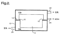
次に、セルスタック内の構造的細部が示されていない図2を参照すると、セルスタック10は、容器12内に設けられ、容器12は、その周囲に沿って水平の棚14を有し、この水平棚は、容器を下側部分12aと上側部分12bに分割している。セルスタック10を構成するフレーム62,63,64は、端部プレート65,66と同様に各側に段部15を有し、したがって、下側部分は、上側部分よりも僅かに幅が狭くなっている。セルスタック10の下側部分は、棚14により構成された長方形空間内に納まり、セルスタック10の上側部分は、棚14にその周囲に沿って封着されている。空気がポンプ(図示せず)からダクト20を通って下側部分12a内に供給されて空気チャンバOを通って流れ、そして上側部分12b内に現れ、空気は、この上側部分から排気ダクト22を通って放出される。液体電解質は、スタック10の一端に供給され、そして、(以下に説明するように)電解質チャンバKを通って流れた後、棚14の頂部上に集まって出口ダクト24を通って流出するようになる。燃料ガス(水素)も又、スタック10の一端に供給され、戻りダクトも又、スタック10のこの端に連結されている。
Referring now to FIG. 2, in which the structural details within the cell stack are not shown, the
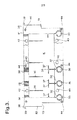
次に図3を参照すると、電解質チャンバKを構成するフレーム62の平面図が示されている。この例では、電解質は、整列状態の孔30により構成された分配ダクトを通ってスタック10内の電解質チャンバKの全てに供給され、孔30は、電解質チャンバKの幅全体にわたって等間隔をおいて設けられている。各孔30は、長くて細い溝32を介して電解質チャンバKの縁と連通し、各コーナ部のところの溝32は、僅かに細くなっている。電解質は、フレーム62の頂縁部に通じる数本の平行な溝34を通ってチャンバKから頂部のところで現れる。
Referring now to FIG. 3, a plan view of the
フレーム62は、電解質チャンバK内に次のバッフルを更に備えており、即ち、チャンバの高さの半分を僅かに超える長さにわたってチャンバKの頂縁部と直交して延び、電解質が出口溝34に向かって上方に流れるよう拘束するバッフル35が設けられ、又、底縁部から上方にチャンバの高さの約1/4のところに切欠き付きクロスピース37を備えると共に各側部のところに側壁から突き出た対応のクロスピース37を備えたT字形バッフル36も又設けられている。溝32は、フレーム62のコーナ部のところの溝は別にして各々2つの出口に、即ち、バッフル30の各側の1つの出口に分岐している。その結果、溝32の入口は、出口溝34の配置場所とは実質的に反対側に位置する。バッフル35,36,37のこの構成により、チャンバK全体を通じて実質的に一様な電解質の流れが得られ、動作中、この実質的に一様な電解質の流れは、セル内の温度変動を著しく減少させ、かかる温度変動は、一実験では、約17℃(バッフルなし)から約3℃(バッフルあり)まで減少し、このうちの平均で約2.5℃は、燃料電池の内部抵抗に起因した不可避的な温度上昇分である。
The
フレーム62の頂部の各端部のところには、隆起部分38及びフレーム62の側部を越えて突き出た湾曲リップ39が設けられている。セルスタック10の使用の際、電解質は、電解質チャンバKを通って孔30により構成された分配ダクト全てから流れて溝34の全てを通って現れる。隆起部分38の各端部は、堰としての役目を果たし、その結果、電解質液は、上述したように両方共フレーム62の頂部を越えて突き出た隣り合う電極要素70相互間に構成された頂部が開いたチャネル41内で各隆起部分38の頂部をちょうど越えたところまで至るようになっている。その結果、電解質の自由表面が容器12の上側部分12b内で空気圧にさらされた状態でフレーム62の頂部を越えて電解質の約2〜3mmの一定深さが存在し、この場合、電解質は、隆起部分38及びリップ39を越えて連続的に流れることができる。すると、電解質は、薄い流れとしてフレーム62の外部上でこれに沿って滴り落ち又は自由に落下して、場合によっては、滴を形成して棚14の頂部上に集まる。電極要素70の隆起部分により、互いに異なるセルからの電解質の流れは、電解質が棚14に至るまで合流しないようになる。
At each end of the top of the
次に図4を参照すると、空気チャンバOを構成するフレーム63の平面図が示されている。容器12の下側部分12aは、プレナムとしての役目を果たし、そして、空気を、スタック内の分配チャネルを通って供給するのではなく、それぞれのフレーム63を通って各空気チャンバOに直接供給することができる。フレーム63の下側半部は、各側に数本の溝52を備え、これら溝は、チャンバOの下側半部と連通している。フレーム63は又、チャンバOの互いに反対側の側部の中点から反対側までの距離の約1/3のところまで突き出たバッフル54を構成している。多数の入口リブ52により、チャンバO内の圧力は、容器12の下側部分12a内の圧力よりもほんの僅か低いようになる。空気は、チャンバOを通って流れて、チャンバOの頂部コーナ部の近くのところに通じる細いS字形溝56を介して現れ、したがって、空気は、容器12の上側部分12b内に流出する。例えば、フレーム63の左側側部には8本の入口溝52が設けられ、長さがその長さの2〜3倍であると共に断面積がこれよりも小さいちょうど1本の出口溝56が設けられている。一例では、各空気チャンバへの空気流量は、約3リットル/分であった。
Next, referring to FIG. 4, a plan view of the
理解されるように、上述の燃料電池スタックは、一例であるに過ぎず、種々の仕方で改造可能であることは理解されよう。フレーム62,63及び更にチャンバK,O,Hは、図示の形状とは異なる形状を有しても良く、電解質チャンバKの出口は、数本の細い溝34に代えて1つ又は2つ以上の広い溝又はスロットを介するものであって良い。一改造例では、電解質チャンバKにウィックとしての役目を果たす多孔質材料又はメッシュを詰め込んでも良い。
It will be appreciated that the fuel cell stack described above is only an example and can be modified in various ways. The
Claims (8)
Applications Claiming Priority (3)
| Application Number | Priority Date | Filing Date | Title |
|---|---|---|---|
| GBGB1007858.2A GB201007858D0 (en) | 2010-05-11 | 2010-05-11 | Fuel cell stacks |
| GB1007858.2 | 2010-05-11 | ||
| PCT/GB2011/050887 WO2011141727A1 (en) | 2010-05-11 | 2011-05-09 | Fuel cell stacks |
Publications (3)
| Publication Number | Publication Date |
|---|---|
| JP2013529361A JP2013529361A (en) | 2013-07-18 |
| JP2013529361A5 JP2013529361A5 (en) | 2014-06-26 |
| JP5866716B2 true JP5866716B2 (en) | 2016-02-17 |
Family
ID=42315147
Family Applications (1)
| Application Number | Title | Priority Date | Filing Date |
|---|---|---|---|
| JP2013509618A Active JP5866716B2 (en) | 2010-05-11 | 2011-05-09 | Fuel cell stack |
Country Status (8)
| Country | Link |
|---|---|
| US (1) | US9083025B2 (en) |
| EP (1) | EP2569815B1 (en) |
| JP (1) | JP5866716B2 (en) |
| KR (1) | KR101891491B1 (en) |
| AU (1) | AU2011251783B2 (en) |
| CA (1) | CA2790530C (en) |
| GB (1) | GB201007858D0 (en) |
| WO (1) | WO2011141727A1 (en) |
Families Citing this family (4)
| Publication number | Priority date | Publication date | Assignee | Title |
|---|---|---|---|---|
| GB201208940D0 (en) | 2012-05-21 | 2012-07-04 | Afc Energy Plc | Fuel cells in stacks |
| GB2540592B (en) * | 2015-07-22 | 2022-02-23 | Afc Energy Plc | Fuel cell stack insert |
| US11444298B2 (en) * | 2019-07-18 | 2022-09-13 | Hyaxiom, Inc. | Electrolyte shunt migration management in a fuel cell stack |
| WO2023193055A1 (en) * | 2022-04-07 | 2023-10-12 | Hysata Pty Ltd | Electro-synthetic or electro-energy cells with liquid features |
Family Cites Families (13)
| Publication number | Priority date | Publication date | Assignee | Title |
|---|---|---|---|---|
| EP0107396B1 (en) | 1982-09-30 | 1988-08-03 | Engelhard Corporation | System for supplying electrolyte to fuel cells |
| JPS59217958A (en) | 1983-05-25 | 1984-12-08 | Fuji Electric Corp Res & Dev Ltd | Device for supplying electrolyte for matrix-type fuel cell |
| US4510213A (en) * | 1983-10-12 | 1985-04-09 | The Unites States Of America As Represented By The Department Of Energy | Fuel cell stack with internal manifolds for reactant gases |
| JPS625570A (en) * | 1985-07-01 | 1987-01-12 | Hitachi Ltd | Electrolyte supplement equipment of fuel cell |
| KR0123727B1 (en) * | 1994-08-17 | 1997-12-09 | 김광호 | Stack for fuel cell |
| US6080290A (en) * | 1997-01-03 | 2000-06-27 | Stuart Energy Systems Corporation | Mono-polar electrochemical system with a double electrode plate |
| US6475653B1 (en) * | 1997-09-01 | 2002-11-05 | Rmg Services Pty Ltd | Non diffusion fuel cell and a process of using the fuel cell |
| US7166383B2 (en) * | 2004-12-07 | 2007-01-23 | Astria Energi Inc. | Electrode structure for stacked alkaline fuel cells |
| KR100726893B1 (en) * | 2006-01-12 | 2007-06-14 | 한국과학기술원 | Construction and flow field type of bipolar plate for direct methanol fuel cell |
| WO2007102026A2 (en) * | 2006-03-07 | 2007-09-13 | Afc Energy Plc | Electrodes of a fuel cell |
| US8293390B2 (en) | 2007-03-28 | 2012-10-23 | Redflow Pty Ltd | Cell stack for a flowing electrolyte battery |
| JP5194569B2 (en) * | 2007-05-31 | 2013-05-08 | トヨタ自動車株式会社 | Fuel cell |
| GB0917143D0 (en) * | 2009-09-30 | 2009-11-11 | Afc Energy Plc | Cell stack |
-
2010
- 2010-05-11 GB GBGB1007858.2A patent/GB201007858D0/en not_active Ceased
-
2011
- 2011-05-09 EP EP11718772.4A patent/EP2569815B1/en active Active
- 2011-05-09 KR KR1020127026938A patent/KR101891491B1/en active IP Right Grant
- 2011-05-09 AU AU2011251783A patent/AU2011251783B2/en active Active
- 2011-05-09 WO PCT/GB2011/050887 patent/WO2011141727A1/en active Application Filing
- 2011-05-09 CA CA2790530A patent/CA2790530C/en active Active
- 2011-05-09 JP JP2013509618A patent/JP5866716B2/en active Active
- 2011-05-09 US US13/695,453 patent/US9083025B2/en active Active
Also Published As
| Publication number | Publication date |
|---|---|
| EP2569815A1 (en) | 2013-03-20 |
| EP2569815B1 (en) | 2014-04-02 |
| KR20130073874A (en) | 2013-07-03 |
| WO2011141727A1 (en) | 2011-11-17 |
| US20130059222A1 (en) | 2013-03-07 |
| AU2011251783A1 (en) | 2012-10-11 |
| CA2790530A1 (en) | 2011-11-17 |
| JP2013529361A (en) | 2013-07-18 |
| GB201007858D0 (en) | 2010-06-23 |
| KR101891491B1 (en) | 2018-08-24 |
| CA2790530C (en) | 2018-09-04 |
| AU2011251783B2 (en) | 2016-02-04 |
| US9083025B2 (en) | 2015-07-14 |
Similar Documents
| Publication | Publication Date | Title |
|---|---|---|
| CN102834958B (en) | For the humidifier of fuel cell | |
| CA2811875C (en) | Lithium accumulator | |
| ITMI990829A1 (en) | COOLED FUEL CELL BY DIRECT INJECTION OF LIQUID WATER | |
| JP5866716B2 (en) | Fuel cell stack | |
| JP2004055564A (en) | Fuel cell assembly | |
| JP6573192B2 (en) | Separator, cell structure and cell stack for fuel cell | |
| KR102143326B1 (en) | Electrolyte circulation in fuel cells stacks with reduced leakage current | |
| JP2007299726A (en) | Separator for fuel cell | |
| JP5603894B2 (en) | Fuel cell | |
| JP5638427B2 (en) | Fuel cell | |
| JP2006236851A (en) | Polymer electrolyte fuel cell | |
| JP2013529361A5 (en) | ||
| JP2006085982A (en) | Cooling structure of solid oxide fuel cell | |
| JP5021219B2 (en) | Fuel cell stack | |
| KR20120074507A (en) | Humidifier for fuel cell | |
| KR102176578B1 (en) | Fuel cell stack including end plate having insertion hole | |
| GB2540592A (en) | Fuel cell stack insert | |
| JP2020105594A (en) | Hydrogen production cell and hydrogen production method using hydrogen production cell | |
| JP2015187952A (en) | solid oxide fuel cell device | |
| JP2018188710A (en) | Water electrolysis apparatus | |
| CN117154126A (en) | Flow field inlet and outlet arrangement structure of fuel cell, fuel cell and system | |
| TW201117460A (en) | Cell stack system block | |
| JPH09180741A (en) | Solid high-molecular electrolyte fuel cell | |
| WO2013108000A1 (en) | Fuel cell stacks | |
| JP2007128675A (en) | Fuel cell |
Legal Events
| Date | Code | Title | Description |
|---|---|---|---|
| A521 | Request for written amendment filed |
Free format text: JAPANESE INTERMEDIATE CODE: A523 Effective date: 20140508 |
|
| A621 | Written request for application examination |
Free format text: JAPANESE INTERMEDIATE CODE: A621 Effective date: 20140508 |
|
| A977 | Report on retrieval |
Free format text: JAPANESE INTERMEDIATE CODE: A971007 Effective date: 20150218 |
|
| A131 | Notification of reasons for refusal |
Free format text: JAPANESE INTERMEDIATE CODE: A131 Effective date: 20150225 |
|
| A601 | Written request for extension of time |
Free format text: JAPANESE INTERMEDIATE CODE: A601 Effective date: 20150522 |
|
| A521 | Request for written amendment filed |
Free format text: JAPANESE INTERMEDIATE CODE: A523 Effective date: 20150825 |
|
| TRDD | Decision of grant or rejection written | ||
| A01 | Written decision to grant a patent or to grant a registration (utility model) |
Free format text: JAPANESE INTERMEDIATE CODE: A01 Effective date: 20151214 |
|
| A61 | First payment of annual fees (during grant procedure) |
Free format text: JAPANESE INTERMEDIATE CODE: A61 Effective date: 20151217 |
|
| R150 | Certificate of patent or registration of utility model |
Ref document number: 5866716 Country of ref document: JP Free format text: JAPANESE INTERMEDIATE CODE: R150 |
|
| R250 | Receipt of annual fees |
Free format text: JAPANESE INTERMEDIATE CODE: R250 |
|
| R250 | Receipt of annual fees |
Free format text: JAPANESE INTERMEDIATE CODE: R250 |
|
| R250 | Receipt of annual fees |
Free format text: JAPANESE INTERMEDIATE CODE: R250 |
|
| R250 | Receipt of annual fees |
Free format text: JAPANESE INTERMEDIATE CODE: R250 |
|
| R250 | Receipt of annual fees |
Free format text: JAPANESE INTERMEDIATE CODE: R250 |
|
| R250 | Receipt of annual fees |
Free format text: JAPANESE INTERMEDIATE CODE: R250 |