JP5863243B2 - sash - Google Patents

sash Download PDF

Info

Publication number
JP5863243B2
JP5863243B2 JP2011002472A JP2011002472A JP5863243B2 JP 5863243 B2 JP5863243 B2 JP 5863243B2 JP 2011002472 A JP2011002472 A JP 2011002472A JP 2011002472 A JP2011002472 A JP 2011002472A JP 5863243 B2 JP5863243 B2 JP 5863243B2
Authority
JP
Japan
Prior art keywords
shoji
view
vertical
corner member
attached
Prior art date
Legal status (The legal status is an assumption and is not a legal conclusion. Google has not performed a legal analysis and makes no representation as to the accuracy of the status listed.)
Active
Application number
JP2011002472A
Other languages
Japanese (ja)
Other versions
JP2012144866A (en
Inventor
裕之 竹林
裕之 竹林
今井 裕一
裕一 今井
藤本 毅
毅 藤本
佑介 栖原
佑介 栖原
亮太 田中
亮太 田中
晃尚 澤田
晃尚 澤田
Current Assignee (The listed assignees may be inaccurate. Google has not performed a legal analysis and makes no representation or warranty as to the accuracy of the list.)
Sankyo Tateyama Inc
Original Assignee
Sankyo Tateyama Inc
Priority date (The priority date is an assumption and is not a legal conclusion. Google has not performed a legal analysis and makes no representation as to the accuracy of the date listed.)
Filing date
Publication date
Application filed by Sankyo Tateyama Inc filed Critical Sankyo Tateyama Inc
Priority to JP2011002472A priority Critical patent/JP5863243B2/en
Publication of JP2012144866A publication Critical patent/JP2012144866A/en
Application granted granted Critical
Publication of JP5863243B2 publication Critical patent/JP5863243B2/en
Active legal-status Critical Current
Anticipated expiration legal-status Critical

Links

Images

Description

本発明は、火災時においても気密性を維持できるサッシに関する。   The present invention relates to a sash capable of maintaining airtightness even in a fire.

サッシは、枠体や障子に取り付けた樹脂製の気密材により気密性を維持しているが、火災時にはこの気密材が融解してしまい、枠体と障子との間に隙間を生じ、その隙間から火炎や可燃性ガスが侵入することがあった。これについては、特許文献1に示すように熱に強い素材からなる気密材を用いることで対策していた(段落0025、段落0026、図3、図4)。しかしながら、熱に強い素材からなる気密材を用いても、融解までの時間を延ばすことはできるが、融解することを防ぐことはできなかった。また、炎熱により障子が変形して、枠体との間に隙間を生じることもあった。これについては、障子に各種の補強材を取り付けることで変形を抑えていた。しかし、障子の変形は、補強材によって完全に抑えることはできず、僅かでも隙間が生じれば気密性は維持されなくなってしまう。そこで、特許文献1に示すように、障子の框に加熱時に発泡する耐火断熱材を取り付け、火災時には耐火断熱材が発泡して障子と枠体の間の隙間を塞ぐものが公知となっている(段落0025、図3)。ところで、一般に障子の框は形材からなり、端部には樹脂製のコーナー部材を取り付けて框の中空部の開口端を塞いである。   The sash maintains its airtightness with a resin-made airtight material attached to the frame and shoji, but in the event of a fire, this airtight material melts, creating a gap between the frame and the shoji. From there, flames and flammable gases sometimes invaded. As shown in Patent Document 1, measures have been taken by using an airtight material made of a heat-resistant material (paragraph 0025, paragraph 0026, FIGS. 3 and 4). However, even when an airtight material made of a heat-resistant material is used, the time to melting can be extended, but it cannot be prevented from melting. Further, the shoji was deformed by the flame heat, and a gap was sometimes formed between the frame and the frame. About this, the deformation | transformation was suppressed by attaching various reinforcing materials to a shoji. However, the deformation of the shoji cannot be completely suppressed by the reinforcing material, and if even a slight gap occurs, the airtightness cannot be maintained. Therefore, as shown in Patent Document 1, it is known that a fireproof heat insulating material that foams when heated is attached to a shoji screen, and that the fireproof heat insulating material foams and closes the gap between the shoji and the frame during a fire. (Paragraph 0025, FIG. 3). By the way, generally, the shoji heel is made of a shape material, and a resin corner member is attached to the end portion to close the open end of the hollow portion of the heel.

特開2004−169453号公報JP 2004-169453 A

このようなコーナー部材については、框に耐火断熱材を取り付けても炎熱から守ることはできない。そして、コーナー部材が融解することで、隙間を生じたり室内外が連通したりして気密性を維持できなくなってしまうことや、サッシの断熱材やコーナー部材が融解して発生した可燃性ガスが、コーナー部材の無くなった框の端部から中空部内を通って室内へ侵入し、可燃性ガスが発火するおそれがあることが問題であった。また、融解したコーナー部材に着火して新たな火元になってしまうことも問題であった。   About such a corner member, even if it attaches a fireproof heat insulating material to a cage | basket, it cannot protect from a flame heat. When the corner member is melted, gaps are created or the interior and the exterior communicate with each other, and the airtightness cannot be maintained, and the sash heat insulating material and the corner member are melted to generate flammable gas. There is a problem that the combustible gas may be ignited by entering the room through the hollow portion from the end portion of the bag where the corner member is lost. Another problem is that the melted corner member ignites and becomes a new fire source.

本発明は、上記事情を鑑みたものであり、コーナー部材の融解を防いで気密性を維持するサッシを提供することを目的とする。   The present invention has been made in view of the above circumstances, and an object thereof is to provide a sash that prevents melting of a corner member and maintains airtightness.

本発明のうち請求項1の発明は、障子を備え、障子は、中空部を有するアルミ部材を備える縦框と、横框と、コーナー部材とを有し、左右の縦框の間に上下の横框を取り付けて框組みし、縦框の上下端部にコーナー部材を取り付けてあって、少なくとも下側のコーナー部材は、不燃材料からなるものであり、コーナー部材は、縦框の中空部内に挿入して縦框の開口端を塞ぐ内側部材と、一部を縦框の他の中空部に挿入して取り付けるか又は縦框の外周面に固定して取り付ける外側部材とに分割してあることを特徴とする。 The invention of claim 1 of the present invention comprises a shoji, and the shoji has a vertical gutter comprising an aluminum member having a hollow portion, a horizontal gutter, and a corner member. Attach a horizontal gutter and assemble it, and attach corner members to the upper and lower ends of the vertical gutter. At least the lower corner member is made of a non-combustible material. It is divided into an inner member that inserts and closes the open end of the downspout, and an outer member that is partly inserted into and attached to the other hollow portion of the downspout or fixed to the outer peripheral surface of the downspout It is characterized by.

本発明のうち請求項の発明によれば、コーナー部材を不燃材料で構成することにより、サッシが炎熱にさらされてもコーナー部材が融解又は焼失することはない。よって、隙間を生じたり室内外が連通したりすることや、サッシの断熱材が融解して発生した可燃性ガスが縦框の中空部内を通って室内へ侵入することを防ぎ、またコーナー部材が融解して可燃性ガスを発生することや、融解したコーナー部材に着火して新たな火元となることを防ぐ。また、コーナー部材を二つに分割することにより、製造が容易になる。たとえば、金属を素材とする場合に、内側部材と外側部材を一体にしてダイカスト鋳造するのは困難であるが、分割してあれば、内側部材には形材を用い、外側部材のみダイカスト鋳造することもできる。また、框の中空部内に挿入して框端部を塞ぐ内側部材と、外観上視認できる外側部材とで、機能性や意匠性を考慮して素材や加工方法を異ならせることもできる。 According to the invention of claim 1 of the present invention, by constituting the corner member with noncombustible materials, sash never corner member is melted or burned off even when exposed to torrid. Therefore, it is possible to prevent a gap or communication between the inside and outside of the room, and to prevent the flammable gas generated by melting the sash heat insulating material from entering the room through the hollow portion of the vertical wall. Prevents melting and generating flammable gas and igniting the melted corner member to become a new source of fire . Also, by splitting the corner member in two, production is facilitated. For example, when a metal is used as a raw material, it is difficult to die cast the inner member and the outer member together, but if it is divided, a shape material is used for the inner member and only the outer member is die cast. You can also. In addition, the material and processing method can be made different in consideration of functionality and design characteristics between the inner member that is inserted into the hollow portion of the heel and closes the heel end portion, and the outer member that can be visually recognized.

室内側障子の召合せ側縦框の下端部を示し、(a)は左側側面図、(b)は正面図、(c)は右側側面図、(d)は平面図、(e)は外側部材を外した状態の左側側面図である。The lower end part of the sump of the indoor side shoji is shown, (a) is a left side view, (b) is a front view, (c) is a right side view, (d) is a plan view, and (e) is an outer side. It is a left side view in the state where a member was removed. 外側部材の取り付けの説明図であり、(a)は左側側面図、(b)は正面図である。It is explanatory drawing of attachment of an outer member, (a) is a left side view, (b) is a front view. 室内側障子の戸当り側縦框の下端部を示し、(a)は左側側面図、(b)は正面図、(c)は右側側面図、(d)は平面図、(e)は外側部材を外した状態の左側側面図である。The lower end of the door-to-door downside of the indoor shoji is shown, (a) is a left side view, (b) is a front view, (c) is a right side view, (d) is a plan view, and (e) is an outer side. It is a left side view in the state where a member was removed. 室外側障子の召合せ側縦框の下端部を示し、(a)は左側側面図、(b)は正面図、(c)は右側側面図、(d)は平面図、(e)は外側部材を外した状態の左側側面図である。The lower end of the sump side of the outdoor shoji is shown, (a) is a left side view, (b) is a front view, (c) is a right side view, (d) is a plan view, and (e) is an outside view. It is a left side view in the state where a member was removed. 室外側障子の戸当り側縦框の下端部を示し、(a)は左側側面図、(b)は正面図、(c)は右側側面図、(d)は平面図、(e)は外側部材を外した状態の左側側面図である。The lower end of the door-to-door downside of the outdoor shoji is shown, (a) is a left side view, (b) is a front view, (c) is a right side view, (d) is a plan view, and (e) is an outer side. It is a left side view in the state where a member was removed. 室内側障子の召合せ側縦框の上端部を示し、(a)は左側側面図、(b)は正面図、(c)は右側側面図である。The upper end part of the summit side scissors of an indoor shoji is shown, (a) is a left side view, (b) is a front view, (c) is a right side view. 室内側障子の戸当り側縦框の上端部を示し、(a)は左側側面図、(b)は正面図、(c)は右側側面図である。The upper end part of the door-to-door side spatula of an indoor side shoji is shown, (a) is a left side view, (b) is a front view, (c) is a right side view. 室外側障子の召合せ側縦框の上端部を示し、(a)は左側側面図、(b)は正面図、(c)は右側側面図である。The upper end part of the summit side downside of an outdoor shoji is shown, (a) is a left side view, (b) is a front view, (c) is a right side view. 室外側障子の戸当り側縦框の上端部を示し、(a)は左側側面図、(b)は正面図、(c)は右側側面図である。The upper end part of the door-to-door side downside of an outdoor shoji is shown, (a) is a left side view, (b) is a front view, (c) is a right side view. 本発明のサッシの縦断面図である。It is a longitudinal cross-sectional view of the sash of this invention. 本発明のサッシの横断面図である。It is a cross-sectional view of the sash of this invention. スペーサ取り付け部分の分解斜視図である。It is a disassembled perspective view of a spacer attachment part. 別実施形態における室内側障子の召合せ側縦框の下端部を示し、(a)は左側側面図、(b)は正面図、(c)は右側側面図、(d)は平面図、(e)は外側部材を外した状態の左側側面図である。The lower end part of the summit side scissors of the indoor shoji in another embodiment is shown, (a) is a left side view, (b) is a front view, (c) is a right side view, (d) is a plan view, ( e) is a left side view with the outer member removed.

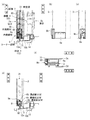
以下、本発明の実施の形態を図面に基づいて説明する。なお、上下は図10中の上下方向を、左右は図11中の左右方向を表す。ここでは、サッシの一例として、図10及び図11に示すように、枠体1に二枚の障子2a,2bを引違いに納めた引違い窓の例を挙げる。枠体1は、上下の横枠(上枠11及び下枠12)と、左右の縦枠13とを四周枠組みしたもので、上枠11の下側面にはレール11a,11bが形成してあり、下枠12の上側面にはレール12a,12bが形成してあって、二枚の障子2a,2bが左右方向スライド自在に納めてある。障子2a,2bは、何れも左右の縦框3と、上下の横框4(上框41及び下框42)と、パネル7とを備え、左右の縦框3の間に上下の横框4を取り付けて(縦框3の内周側面に横框4の端面を当接させて、縦框3の外周側からボルト止めしてある)四周框組みして、パネル7を嵌め込んだものである。なお、このサッシは、障子2a,2bの各縦框3及び横框4が(室外側の障子2aの召合せ側の縦框3を除く)、室外側のアルミ部材3c,4cと室内側の樹脂部材3d,4dとを組み合わせて構成された、いわゆる複合サッシである。また、室外側の障子2aの召合せ側の縦框3と、その他の縦框3及び横框4のアルミ部材3c,4cは、何れも形材からなり中空部31を有する。さらに、上枠11及び下枠12は、何れも室外側と室内側の二部材に分割してあり、二部材をウレタンからなる断熱材14で連結してある。   Hereinafter, embodiments of the present invention will be described with reference to the drawings. Note that the vertical direction indicates the vertical direction in FIG. 10, and the horizontal direction indicates the horizontal direction in FIG. Here, as an example of a sash, as shown in FIGS. 10 and 11, an example of a sliding window in which two shojis 2a and 2b are placed in a frame 1 in a sliding manner will be given. The frame 1 is composed of four upper and lower horizontal frames (upper frame 11 and lower frame 12) and left and right vertical frames 13, and rails 11a and 11b are formed on the lower surface of the upper frame 11. Rails 12a and 12b are formed on the upper side surface of the lower frame 12, and the two shojis 2a and 2b are slidable in the left-right direction. Each of the shojis 2a and 2b includes a left and right downside spatula 3, an upper and lower downside spatula 4 (upper side 41 and lower bottom side 42), and a panel 7. Is attached with the panel 7 (four ends are brought into contact with the inner peripheral side surface of the vertical rod 3 and bolted from the outer peripheral side of the vertical rod 3) and the panel 7 is fitted. is there. In this sash, the vertical rod 3 and the horizontal rod 4 of the shojis 2a and 2b (excluding the vertical rod 3 on the summing side of the outdoor shoji 2a) are connected to the outdoor side aluminum members 3c and 4c and the indoor side. This is a so-called composite sash formed by combining the resin members 3d and 4d. Further, the vertical rod 3 on the summit side of the outdoor shoji 2a and the aluminum members 3c, 4c of the other vertical rod 3 and horizontal rod 4 are both made of a shape and have a hollow portion 31. Furthermore, the upper frame 11 and the lower frame 12 are each divided into two members, the outdoor side and the indoor side, and the two members are connected by a heat insulating material 14 made of urethane.

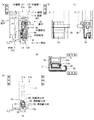
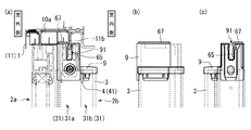
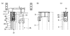
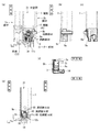
そして、各縦框3の上下端部には、コーナー部材9を取り付けて中空部31の開口端を塞いである。図1に示すのは、室内側の障子2bの召合せ側の縦框3の下端部であり、この縦框3のアルミ部材3cは、室外側と室内側に二つの中空部31(室外側中空部31a、室内側中空部31b)を有する。そしてコーナー部材9は、内側部材9aと、外側部材9bからなる。内側部材9aは、断面略コ字形状のアルミ形材からなり、コ字形の溝部91の開口部を下側に向けて室外側中空部31aの開口端に挿入して外側からネジ止めしてあって、溝部91がレール12bを跨ぐ。そして図1(d)に示すように、内側部材9aの横断面の大きさは、室外側中空部31aの横断面の大きさに略等しく、内側部材9aが室外側中空部31aの開口端を塞いでいる。また、内側部材9aの室外側下端部には、レール12bに当接するタイト材92を取り付けてある。一方、外側部材9bは、アルミをダイカスト鋳造して形成したものであって、図2に示すように、キャップ93と、カバー94と、シールピース95の三つの部材からなる。キャップ93は、略平板形状で周囲に起立片を有する蓋部931と、蓋部931の上面に形成した上部突起932と、蓋部931の室外側から下方に延びる下部片933と、下部片933の室外側下端部に形成した下部突起934とを備えるものであり、上部突起932を縦框3の室内側中空部31bの開口端に挿入し、下部突起934を縦框3の下端に形成した切欠32に係合させて取り付けてある。また、カバー94は、略平板形状で、縦框3の見込面にネジ止めしてある。さらに、シールピース95も略平板形状で、カバー94の下端部に重ねるようにネジ止めしてある。   And the corner member 9 is attached to the upper-lower end part of each vertical gutter 3, and the opening end of the hollow part 31 is plugged up. FIG. 1 shows a lower end portion of the vertical rod 3 on the summon side of the shoji 2b on the indoor side. The aluminum member 3c of the vertical rod 3 has two hollow portions 31 (outdoors on the outdoor side and the indoor side). It has a hollow part 31a and an indoor hollow part 31b). The corner member 9 includes an inner member 9a and an outer member 9b. The inner member 9a is made of an aluminum member having a substantially U-shaped cross section, and is inserted into the opening end of the outdoor hollow portion 31a with the opening of the U-shaped groove 91 facing downward and is screwed from the outside. Then, the groove portion 91 straddles the rail 12b. And as shown in FIG.1 (d), the magnitude | size of the cross section of the inner side member 9a is substantially equal to the magnitude | size of the cross section of the outdoor side hollow part 31a, and the inner side member 9a shows the opening end of the outdoor side hollow part 31a. It is blocking. Further, a tight material 92 that is in contact with the rail 12b is attached to the lower end on the outdoor side of the inner member 9a. On the other hand, the outer member 9b is formed by die-casting aluminum and includes three members, a cap 93, a cover 94, and a seal piece 95, as shown in FIG. The cap 93 has a substantially flat plate-shaped lid portion 931 having standing pieces around it, an upper protrusion 932 formed on the upper surface of the lid portion 931, a lower piece 933 extending downward from the outdoor side of the lid portion 931, and a lower piece 933. The lower protrusion 934 formed on the lower end of the outdoor side of the inner wall of the vertical shaft 3 is inserted, the upper protrusion 932 is inserted into the open end of the indoor hollow portion 31b of the vertical shaft 3, and the lower protrusion 934 is formed on the lower end of the vertical shaft 3. It is engaged with the notch 32 and attached. The cover 94 has a substantially flat plate shape and is screwed to the expected surface of the vertical rod 3. Further, the seal piece 95 has a substantially flat plate shape and is screwed so as to overlap the lower end portion of the cover 94.

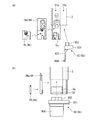
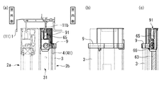
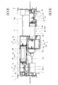
また、図3〜5に示すように、室内側の障子2bの戸当り側、室外側の障子2aの召合せ側及び戸当り側の縦框3についても、下端に内側部材9aと外側部材9bからなるコーナー部材9を取り付けて中空部31の開口端を塞いである。これらの縦框3においては、中空部31は一つであり、内側部材9aを中空部31の開口端に挿入してあり、外側部材9bを縦框3の外周面にネジ止めしてある。   Moreover, as shown in FIGS. 3-5, the inner side member 9a and the outer side member 9b are arranged at the lower ends of the door sliding side of the indoor shoji 2b, the summoning side of the outdoor shoji 2a, and the vertical rod 3 on the door sliding side. A corner member 9 is attached to close the open end of the hollow portion 31. In these vertical rods 3, there is one hollow portion 31, the inner member 9 a is inserted into the open end of the hollow portion 31, and the outer member 9 b is screwed to the outer peripheral surface of the vertical rod 3.

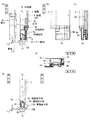
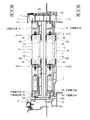
さらに、図6〜9に示すように、各縦框3の上端部についても、コーナー部材9を取り付けて中空部31の開口端を塞いである。これらの上端部のコーナー部材9は、従来の樹脂製で一体成形されたものであって、レール11a,11bを跨ぐ溝部91を有する。上端部のコーナー部材9を樹脂製のものとしたのは、火災時において一般に炎は下側から回るので、少なくとも縦框3の下端のコーナー部材9が不燃材料からなるものであればよいからである。また上端部のコーナー部材9はアルミ形材からなるレール11a,11bと直接接触するので、樹脂製にすることで接触音を低減する効果もある。   Furthermore, as shown in FIGS. 6 to 9, the corner member 9 is also attached to the upper end portion of each vertical rod 3 to close the open end of the hollow portion 31. The corner members 9 at the upper end portions are integrally formed of a conventional resin and have a groove portion 91 that straddles the rails 11a and 11b. The corner member 9 at the upper end is made of resin because, in general, flames rotate from the lower side in the event of a fire, so it is sufficient that at least the corner member 9 at the lower end of the vertical rod 3 is made of a non-combustible material. is there. Moreover, since the corner member 9 at the upper end portion is in direct contact with the rails 11a and 11b made of an aluminum shape, there is an effect of reducing contact noise by using resin.

このように、縦框3の下端のコーナー部材9(内側部材9a及び外側部材9b)を不燃材料であるアルミで構成することにより、サッシが炎熱にさらされてもコーナー部材9が融解又は焼失することはなく、隙間を生じたり室内外が連通したりすることを防ぐ。また、内側部材9aが縦框3の端部を確実に塞ぐので(さらに室内側の障子2bの召合せ側の縦框3においては、外側部材9bのキャップ93が室内側中空部31bを塞ぐ)、下枠12の断熱材14が融解して発生した可燃性ガスが中空部31内を通って室内へ侵入することも防ぐ。さらに、コーナー部材9が融解して可燃性ガスを発生することや、融解したコーナー部材9に着火して新たな火元となることもない。また、コーナー部材9は、内側部材9aとしてアルミ形材を用い、外側部材9bのみをアルミでダイカスト鋳造したものであり、製造が容易である。さらに、縦框3の中空部31内に挿入して端部を塞ぐ内側部材9aと、外観上視認できる外側部材9bとで、機能性や意匠性を考慮して素材や加工方法を異ならせることもできる。   Thus, by constituting the corner member 9 (the inner member 9a and the outer member 9b) at the lower end of the vertical rod 3 with aluminum which is a non-combustible material, the corner member 9 is melted or burnt even if the sash is exposed to flame heat. It will not prevent any gaps or indoor / outdoor communication. Further, since the inner member 9a reliably closes the end portion of the vertical rod 3 (in addition, in the vertical rod 3 on the calling side of the indoor shoji 2b, the cap 93 of the outer member 9b closes the indoor hollow portion 31b). The flammable gas generated by melting the heat insulating material 14 of the lower frame 12 is also prevented from entering the room through the hollow portion 31. Further, the corner member 9 is not melted to generate flammable gas, and the melted corner member 9 is not ignited to become a new fire source. Further, the corner member 9 is formed by using an aluminum shape as the inner member 9a and die-casting only the outer member 9b with aluminum, and is easily manufactured. Furthermore, materials and processing methods are made different in consideration of functionality and design characteristics between the inner member 9a that is inserted into the hollow portion 31 of the vertical shaft 3 and closes the end portion, and the outer member 9b that can be visually recognized. You can also.

また、図1、図3〜5に示すように、各コーナー部材9の内側部材9aの溝部91底面及び溝部91内側の室外側及び室内側の壁面に、溝部耐火材65を取り付けてある。溝部耐火材65は、エポキシ系の素材からなり、約200℃で発泡して厚さ方向(取付面に対して垂直方向)に膨張するものであって、火災時に発泡して下枠12(レール12a,12b)との隙間を塞ぐ(後述の各耐火材も同じ素材からなるものである)。なお、図4に示すように、室外側の障子2aの召合せ側の縦框3の中空部31は見込幅が長いので、ここに挿入する内側部材9aも見込幅が長くなっている。そこで、内側部材9aの室内側に補助中空部96を形成することで、溝部91の幅を狭くして、溝部91内側の室内側の壁面に取り付けた溝部耐火材65が発泡時に確実にレール12aとの隙間を塞ぐようにしてある。さらに、図3(c)及び図5(a)に示すように、戸当り側の縦框3において、コーナー部材9の外側部材9bの外周側面(戸当り面)に、上下に延びる戸当耐火材66を取り付けてある。そして図6〜9に示すように、各縦框3の上端部のコーナー部材にも、同様に溝部耐火材65(室内側の縦框3のコーナー部材9については、溝部91内側の室外側の壁面のみ、室外側の縦框3のコーナー部材9については、溝部91内側の室内側及び室外側の壁面のみ、)及び戸当耐火材66を取り付けてある。   Further, as shown in FIGS. 1 and 3 to 5, a groove refractory material 65 is attached to the bottom surface of the groove 91 of the inner member 9 a of each corner member 9, and the outdoor and indoor wall surfaces inside the groove 91. The groove portion refractory material 65 is made of an epoxy-based material, and foams at about 200 ° C. and expands in the thickness direction (perpendicular to the mounting surface). 12a and 12b) (the refractory materials described later are also made of the same material). In addition, as shown in FIG. 4, since the hollow part 31 of the vertical fence 3 of the summit side of the outdoor shoji 2a has a long expected width, the inner member 9a inserted here also has a long expected width. Therefore, by forming the auxiliary hollow portion 96 on the indoor side of the inner member 9a, the width of the groove portion 91 is reduced, and the groove portion refractory material 65 attached to the wall surface on the indoor side inside the groove portion 91 reliably ensures the rail 12a. It is designed to close the gap. Further, as shown in FIGS. 3 (c) and 5 (a), the door toe fireproof extending vertically on the outer peripheral side surface (door contact surface) of the outer member 9 b of the corner member 9 in the vertical rod 3 on the door contact side. A material 66 is attached. And as shown in FIGS. 6-9, similarly to the corner member of the upper end part of each vertical gutter 3, the groove part refractory material 65 (for the corner member 9 of the vertical gutter 3 on the indoor side, Only the wall surface, and the corner member 9 of the vertical gutter 3 on the outdoor side, only the wall surface inside the groove portion 91 and the wall surface on the outdoor side) and the door-to-door refractory material 66 are attached.

さらに、上框41の上側面には上框耐火材61が、下框42の下部内側面には下框耐火材62が、戸当り側の縦框3の戸当り面には縦框耐火材63が、室外側の障子2aの召合せ側の縦框3の召合せ面には召合耐火材64が、それぞれ框の略全長にわたって取り付けてある。何れも、サッシが炎熱にさらされた際に発泡して、枠体1と障子2a,2b又は障子2a,2b同士の間に生じる隙間を塞いで、サッシの気密性を維持するためのものである。そして、横框4に取り付けた上框耐火材61及び下框耐火材62と、コーナー部材9に取り付けた溝部耐火材65とは、炎熱にさらされた際に膨張して互いに密接し、また縦框3に取り付けた縦框耐火材63と、コーナー部材9に取り付けた戸当耐火材66とは、炎熱にさらされた際に膨張して互い密接し、さらに溝部耐火材65と戸当耐火材66とは、炎熱にさらされた際に膨張して互いに密接する。こうして、障子2a,2bの周囲に連続した耐火ラインが形成され、サッシが炎熱にさらされて気密材が融解したり障子2a,2bが変形したりした場合でも、障子2a,2bと枠体1との間を隙間なく塞ぎ、サッシの気密性を維持することができる。   Further, an upper refractory material 61 is provided on the upper surface of the upper ridge 41, a lower refractory material 62 is provided on the lower inner surface of the lower ridge 42, and a vertical refractory material is provided on the door contact surface of the vertical ridge 3 on the door-to-door side. 63, the summoned refractory material 64 is attached to the summit surface of the vertical fence 3 on the summit side of the shoji 2a on the outdoor side over the substantially entire length of the saddle. In either case, the sash is foamed when exposed to flame heat, and the gap between the frame 1 and the shoji 2a, 2b or shoji 2a, 2b is closed to maintain the airtightness of the sash. is there. Then, the upper refractory material 61 and the lower refractory material 62 attached to the horizontal rail 4 and the groove refractory material 65 attached to the corner member 9 expand and come into close contact with each other when exposed to flame heat. The vertical fire retardant material 63 attached to the eaves 3 and the door-to-door refractory material 66 attached to the corner member 9 expand and come into close contact with each other when exposed to flame heat, and further the groove refractory material 65 and the door-to-door refractory material. 66 swell and close to each other when exposed to flame heat. Thus, a continuous fireproof line is formed around the shojis 2a and 2b, and the shojis 2a and 2b and the frame 1 even when the sash is exposed to flame heat and the hermetic material melts or the shojis 2a and 2b are deformed. It is possible to maintain the airtightness of the sash.

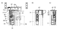
また、図4に示すように、室外側の障子2aの召合せ側の縦框3の下端部の内側部材9aの下面(溝部91の室内側)に、溝部91に沿って端部耐火材67を取り付けてある。そして、下枠12の、召合せ側の縦框3のコーナー部材9に対向する位置には、貫通孔71が形成してあり、この貫通孔71に、樹脂製で室内外方向に連通する気密ピース10a(止水ピース)を嵌め込んで取り付けてあり、これは、図4(a)に示すように、室内側への水の流入を抑えるためのものである。気密ピース10aは、それ自体が室内外に連通しているものであるから、無くなるとサッシの室内外が連通してしまうことになる。しかし、火災時には、内側部材9a下面の端部耐火材67が発泡して気密ピース10aを覆うので、気密ピース10aが炎熱にさらされて融解し、室内外が連通して気密性が維持できなくなることを防ぐ。また、図6及び図8に示すように、召合せ側の縦框3の上端部のコーナー部材9の上面(室内側の障子2bにおいては溝部91の室外側、室外側の障子2aにおいては溝部91の室内側)にも、溝部91に沿って端部耐火材67を取り付けてある。さらに上枠11の、召合せ側の縦框3のコーナー部材9に対向する位置には気密ピース10aとして風の侵入や音もれを抑えるための風止板を取り付けてあり、火災時にはコーナー部材9上面の端部耐火材67及び上框耐火材61が発泡して気密ピース10aを覆う。なお、室外側の障子2aの戸当り側の縦框3の下部には、図5(a)及び図11に示すように、二つの貫通孔71が形成してあり、これは排気孔としての機能を有するものである。そして、貫通孔71を塞ぐカバー材10bとして、室内側の障子2bのストッパーを取り付けてある。よって、室外側の障子2aの戸当り側の縦框3の下端部の内側部材9aの下面にも端部耐火材を取り付けて、火災時にカバー材10bを覆うようにしてもよい。さらに、他の箇所のコーナー部材にも端部耐火材を取り付けて、火災時に、対向する位置にある部材を覆うようにしてもよい。   Further, as shown in FIG. 4, an end portion refractory material 67 is formed along the groove portion 91 on the lower surface of the inner member 9 a at the lower end portion of the vertical rod 3 on the summoning side of the outdoor shoji 2 a (inner side of the groove portion 91). Is attached. A through-hole 71 is formed at a position of the lower frame 12 facing the corner member 9 of the summit 3 on the summit side, and the through-hole 71 is made of resin and communicates in the indoor and outdoor directions. A piece 10a (water stop piece) is fitted and attached, as shown in FIG. 4 (a), to suppress the inflow of water into the room. Since the airtight piece 10a itself communicates with the inside and outside of the room, if the airtight piece 10a disappears, the inside and outside of the sash communicate with each other. However, in the event of a fire, the end refractory material 67 on the lower surface of the inner member 9a foams and covers the airtight piece 10a, so that the airtight piece 10a is exposed to flame heat and melts, and the interior and the exterior communicate with each other and the airtightness cannot be maintained. To prevent that. Moreover, as shown in FIG.6 and FIG.8, the upper surface of the corner member 9 of the upper end part of the summit 3 on the summoning side (the outdoor side of the groove part 91 in the indoor shoji 2b, the groove part in the outdoor shoji 2a) The end refractory material 67 is also attached along the groove portion 91 to the indoor side 91. Further, an airtight plate 10a is installed as an airtight piece 10a at a position of the upper frame 11 facing the corner member 9 of the summit 3 on the summoning side. 9 The end refractory material 67 and the upper refractory material 61 on the upper surface foam and cover the airtight piece 10a. In addition, as shown in FIG. 5A and FIG. 11, two through holes 71 are formed in the lower part of the vertical fence 3 on the door side of the outdoor shoji 2a, which serves as an exhaust hole. It has a function. And the stopper of the indoor shoji 2b is attached as the cover material 10b which block | closes the through-hole 71. FIG. Therefore, you may make it cover the cover material 10b at the time of a fire by attaching an edge part fireproof material also to the lower surface of the inner member 9a of the lower end part of the vertical fence 3 on the door stop side of the outdoor shoji 2a. Furthermore, an end portion refractory material may be attached to other corner members so as to cover the members at the opposing positions in the event of a fire.

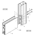
なお、図10及び図11に示すように、本発明のサッシの障子2a,2bにおいては、パネル7の全周にわたって、鉄製で断面コ字形のパネル支持材100を取り付けてある。これは、サッシが炎熱にさらされて縦框3及び横框4が融解した場合にパネル7が外れるのを防ぎ、サッシの気密性を維持するためのものである。   10 and 11, in the sash shoji 2a and 2b of the sash according to the present invention, a panel support member 100 made of iron and having a U-shaped cross section is attached to the entire periphery of the panel 7. This is to prevent the panel 7 from coming off when the sash is exposed to flame heat and the downpipe 3 and the downside 4 are melted, and to maintain the airtightness of the sash.

また、各縦框3の中空部31内(室内側の障子2bの召合せ側の縦框3においては、室外側中空部31a内)には、鉄製で断面コ字形の補強材110を挿入してある。補強材110は縦框3の全長にわたるもので、外側からネジ止めしてある。これは、サッシが炎熱にさらされた際に、縦框3の伸びを抑えるためのものである。   Further, a reinforcing material 110 made of iron and having a U-shaped cross section is inserted into the hollow portion 31 of each vertical rod 3 (in the outdoor hollow portion 31a in the vertical rod 3 on the summit side of the indoor shoji 2b). It is. The reinforcing material 110 extends over the entire length of the vertical rod 3 and is screwed from the outside. This is for suppressing the elongation of the downpipe 3 when the sash is exposed to flame heat.

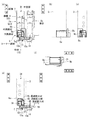
さらに、縦框3の内周側面と横框4の端面の間には、スペーサ5が取り付けてある。図12は、下框42の場合を示したものであり、スペーサ5は、長方形状で、上下に二つのボルト孔51が形成してあり、縦框3と下框42を接合するボルト8が貫通している。また、スペーサ5の室外側と室内側には、上下方向に延びる補助耐火材6を取り付けてある。そして、縦框と上框の間にも略同様にスペーサ及び補助耐火材を取り付けてある。なお、スペーサ5は、ABS樹脂からなるもので、約100℃で軟化し始め、約300℃で融解する。融解する際には、可燃性のガスを生じる。火災時には、サッシが炎熱にさらされて、まずスペーサ5が軟化し、温度上昇に伴って伸び始める横框4に押しつぶされることで横框4の伸びを吸収する。そして、最終的にはスペーサ5が融解して、厚さ分だけ横框4の伸びを吸収して、障子の変形を防ぐことができる。そして、補助耐火材6が発泡して縦框3と横框4の間の隙間を塞ぎ、煙の流通を遮断し、またスペーサ5が融解することにより発生するガスも遮断し、さらに融解したスペーサ5を包み込んで、その流出を防ぐ。また、発泡した補助耐火材6は空気層を有し断熱性に優れているから、直接炎熱にさらされている部位から他の部位への熱伝導を抑え、熱による損傷範囲を小さくすることができる。なお、スペーサ5の大きさは横框4端面の大きさよりも小さくなっており、これはスペーサ5が大きすぎると溶け残りを生じて横框4の伸び吸収の妨げになるからである。一方、補助耐火材6の上下方向長さは横框4端面の上下方向長さと略同一であり、横框4と縦框3の間の隙間を確実に塞ぐ。また、横框4のうち伸びるのはアルミ部材4cであり、樹脂部材4dは溶けてしまうから、スペーサ5及び補助耐火材6は、アルミ部材4c部分に当接させてある。さらに、補助耐火材6をスペーサ5の室外側と室内側の両方に取り付けたことにより、サッシが室外側と室内側のどちらから炎熱にさらされた場合であっても、補助耐火材6が確実に発泡して隙間を塞ぐ。   Further, a spacer 5 is attached between the inner peripheral side surface of the vertical rod 3 and the end surface of the horizontal rod 4. FIG. 12 shows the case of the lower rod 42. The spacer 5 has a rectangular shape with two bolt holes 51 formed on the upper and lower sides, and the bolt 8 that joins the vertical rod 3 and the lower rod 42 is provided. It penetrates. Further, auxiliary refractory materials 6 extending in the vertical direction are attached to the outdoor side and the indoor side of the spacer 5. In addition, a spacer and an auxiliary refractory material are attached between the vertical hook and the upper hook in a similar manner. The spacer 5 is made of ABS resin, starts to soften at about 100 ° C., and melts at about 300 ° C. When it melts, it produces flammable gas. In the event of a fire, the sash is exposed to flame heat, and the spacer 5 is first softened, and is crushed by the horizontal bar 4 that begins to expand as the temperature rises, thereby absorbing the expansion of the horizontal bar 4. And finally, the spacer 5 melt | dissolves, the extension of the reed 4 is absorbed only by thickness, and the deformation | transformation of a shoji can be prevented. Then, the auxiliary refractory material 6 foams and closes the gap between the vertical fence 3 and the horizontal fence 4, blocks the flow of smoke, blocks the gas generated when the spacer 5 melts, and further melts the spacer. Wrap 5 and prevent its outflow. In addition, since the foamed auxiliary refractory material 6 has an air layer and is excellent in heat insulation, it can suppress heat conduction from the part directly exposed to flame heat to other parts, and reduce the damage range due to heat. it can. In addition, the size of the spacer 5 is smaller than the size of the end face of the horizontal bar 4. This is because, if the spacer 5 is too large, undissolved residue is generated and obstruction of the horizontal bar 4 is absorbed. On the other hand, the vertical length of the auxiliary refractory material 6 is substantially the same as the vertical length of the end surface of the horizontal bar 4, and reliably closes the gap between the horizontal bar 4 and the vertical bar 3. In addition, since the aluminum member 4c extends out of the horizontal bar 4 and the resin member 4d melts, the spacer 5 and the auxiliary refractory material 6 are brought into contact with the aluminum member 4c portion. Furthermore, by attaching the auxiliary refractory material 6 to both the outdoor side and the indoor side of the spacer 5, the auxiliary refractory material 6 is surely secured even if the sash is exposed to flame heat from either the outdoor side or the indoor side. Foam to close the gap.

また、図13に示すのは、別実施形態の室内側の障子2bの召合せ側の縦框3の下端部であり、この実施形態では、中空部31が一つである。この場合も、コーナー部材9は、内側部材9aと、外側部材9bからなる。内側部材9aは、断面略コ字形状のアルミ形材からなり、コ字形の溝部91の開口部を下側に向けて中空部31の開口端に挿入してあって、溝部91がレール12bを跨ぐ。そして図13(d)に示すように、内側部材9aの横断面の大きさは、中空部31の横断面の大きさに略等しく、内側部材9aが中空部31の開口端を塞いでいる。また、内側部材9aの室外側下端部には、レール12bに当接するタイト材92を取り付けてある。そして、溝部91底面及び溝部91内側の室外側及び室内側の壁面に、溝部耐火材65を取り付けてある。一方、外側部材9bは、アルミをダイカスト鋳造して形成したものであって、縦框3の外周面にネジ止めしてある。   Moreover, what is shown in FIG. 13 is the lower end part of the vertical rod 3 on the summoning side of the shoji 2b on the indoor side of another embodiment, and in this embodiment, there is one hollow portion 31. Also in this case, the corner member 9 includes an inner member 9a and an outer member 9b. The inner member 9a is made of an aluminum shape having a substantially U-shaped cross section, and is inserted into the opening end of the hollow portion 31 with the opening of the U-shaped groove 91 facing downward, and the groove 91 connects the rail 12b. Straddle. As shown in FIG. 13D, the size of the cross section of the inner member 9 a is substantially equal to the size of the cross section of the hollow portion 31, and the inner member 9 a closes the opening end of the hollow portion 31. Further, a tight material 92 that is in contact with the rail 12b is attached to the lower end on the outdoor side of the inner member 9a. And the groove part refractory material 65 is attached to the wall surface of the groove part 91 bottom face, the outdoor side inside the groove part 91, and the indoor side. On the other hand, the outer member 9b is formed by die-casting aluminum and is screwed to the outer peripheral surface of the vertical rod 3.

本発明は、上記の実施形態に限定されない。たとえば、縦框上端のコーナー部材についても、不燃材料からなるものを用いてもよい。その際には、コーナー部材とレールの接触部にクッション材を取り付けて、接触音を低減することが望ましい。また、不燃材料からなるコーナー部材は、内側部材と外側部材とを一体に成形してもよい。さらに、不燃材料としては、アルミ以外に鉄やステンレスなどの火炎の熱によって容易に融解しない金属を用いてもよいし、その他、火災時に一定時間形状を保つことができるものであれば、ガラス、石、不燃加工を施した木材等、種々の素材を用いることもできる。   The present invention is not limited to the above embodiment. For example, the corner member at the upper end of the vertical shaft may be made of a non-combustible material. In that case, it is desirable to reduce the contact sound by attaching a cushion material to the contact portion between the corner member and the rail. Further, the corner member made of a non-combustible material may be formed by integrally forming the inner member and the outer member. Furthermore, as the incombustible material, a metal that is not easily melted by the heat of a flame such as iron or stainless steel in addition to aluminum may be used. Various materials such as stones and non-combustible wood can also be used.

1 枠体
2a,2b 障子
3 縦框
4 横框
9 コーナー部材
9a 内側部材
9b 外側部材
31 中空部
61 上框耐火材(耐火材)
62 下框耐火材(耐火材)
65 溝部耐火材(耐火材)
DESCRIPTION OF SYMBOLS 1 Frame 2a, 2b Shoji 3 Longitudinal ridge 4 Horizontal ridge 9 Corner member 9a Inner member 9b Outer member 31 Hollow part 61 Upper ridge fireproof material (fireproof material)
62 Shimojo fireproof material (fireproof material)
65 groove refractory material (refractory material)

Claims (1)

障子を備え、障子は、中空部を有するアルミ部材を備える縦框と、横框と、コーナー部材とを有し、左右の縦框の間に上下の横框を取り付けて框組みし、縦框の上下端部にコーナー部材を取り付けてあって、少なくとも下側のコーナー部材は、不燃材料からなるものであり、コーナー部材は、縦框の中空部内に挿入して縦框の開口端を塞ぐ内側部材と、一部を縦框の他の中空部に挿入して取り付けるか又は縦框の外周面に固定して取り付ける外側部材とに分割してあることを特徴とするサッシ。 The shoji has a vertical gutter comprising an aluminum member having a hollow part, a horizontal gutter, and a corner member. The vertical gutter is assembled by attaching upper and lower gutters between the left and right gutters. A corner member is attached to the upper and lower end portions, and at least the lower corner member is made of a non-combustible material, and the corner member is inserted inside the hollow portion of the vertical gutter and closes the open end of the vertical gutter. A sash, characterized in that it is divided into a member and an outer member that is attached by being inserted into another hollow part of the vertical gutter or fixed to the outer peripheral surface of the vertical gutter.
JP2011002472A 2011-01-07 2011-01-07 sash Active JP5863243B2 (en)

Priority Applications (1)

Application Number Priority Date Filing Date Title
JP2011002472A JP5863243B2 (en) 2011-01-07 2011-01-07 sash

Applications Claiming Priority (1)

Application Number Priority Date Filing Date Title
JP2011002472A JP5863243B2 (en) 2011-01-07 2011-01-07 sash

Publications (2)

Publication Number Publication Date
JP2012144866A JP2012144866A (en) 2012-08-02
JP5863243B2 true JP5863243B2 (en) 2016-02-16

Family

ID=46788707

Family Applications (1)

Application Number Title Priority Date Filing Date
JP2011002472A Active JP5863243B2 (en) 2011-01-07 2011-01-07 sash

Country Status (1)

Country Link
JP (1) JP5863243B2 (en)

Families Citing this family (5)

* Cited by examiner, † Cited by third party
Publication number Priority date Publication date Assignee Title
JP5861201B2 (en) * 2011-11-30 2016-02-16 株式会社Lixil sash
JP5861202B2 (en) * 2011-11-30 2016-02-16 株式会社Lixil sash
JP6236285B2 (en) * 2013-10-29 2017-11-22 三協立山株式会社 Fireproof sliding door
JP6254915B2 (en) * 2014-07-30 2017-12-27 Ykk Ap株式会社 Joinery
JP6537913B2 (en) * 2015-07-23 2019-07-03 Ykk Ap株式会社 Joiner

Family Cites Families (9)

* Cited by examiner, † Cited by third party
Publication number Priority date Publication date Assignee Title
JPH0423186Y2 (en) * 1985-06-27 1992-05-28
JPH078774Y2 (en) * 1991-02-28 1995-03-06 近畿工業株式会社 Structure of wooden fire door corner member
JP2593641Y2 (en) * 1992-09-30 1999-04-12 三協アルミニウム工業株式会社 Connection structure of hollow members
JPH07268986A (en) * 1994-04-04 1995-10-17 Nippon Jutaku Panel Kogyo Kyodo Kumiai Fire door
JP3520480B2 (en) * 1995-06-07 2004-04-19 株式会社フジタ Reinforced core connection structure for fire protection unit
JP2001241266A (en) * 1999-12-24 2001-09-04 Ykk Architectural Products Inc Fittings
JP4072421B2 (en) * 2002-11-21 2008-04-09 新日軽株式会社 Fire protection structure in composite sash
JP4229286B2 (en) * 2005-04-28 2009-02-25 Ykk Ap株式会社 Resin window
JP2009228350A (en) * 2008-03-25 2009-10-08 Shin Nikkei Co Ltd Resin sash

Also Published As

Publication number Publication date
JP2012144866A (en) 2012-08-02

Similar Documents

Publication Publication Date Title
JP5658079B2 (en) sash
JP5918603B2 (en) sash
JP5778848B2 (en) Joinery
JP6068125B2 (en) Joinery
JP5651008B2 (en) Fire prevention structure of multi-layer glass window
JP5752027B2 (en) Joinery
JP5863243B2 (en) sash
JP5982198B2 (en) Joinery
JP5646977B2 (en) sash
JP5746961B2 (en) Joinery
JP2012122310A (en) Sash
JP5653870B2 (en) sash
JP6396673B2 (en) Resin window
JP5749129B2 (en) Opening building materials
JP6246251B2 (en) Joinery
JP6017299B2 (en) Joinery
JP5981288B2 (en) Joinery
JP5653896B2 (en) Joinery
JP5693424B2 (en) sash
JP6173724B2 (en) Doors and joinery
JP6240954B2 (en) Opening device
JP5778850B2 (en) Joinery
JP6155154B2 (en) sash
JP6023229B2 (en) Opening building materials
JP7010731B2 (en) Fire protection fittings

Legal Events

Date Code Title Description
A621 Written request for application examination

Free format text: JAPANESE INTERMEDIATE CODE: A621

Effective date: 20130729

A977 Report on retrieval

Free format text: JAPANESE INTERMEDIATE CODE: A971007

Effective date: 20140217

A131 Notification of reasons for refusal

Free format text: JAPANESE INTERMEDIATE CODE: A131

Effective date: 20140225

A521 Written amendment

Free format text: JAPANESE INTERMEDIATE CODE: A523

Effective date: 20140416

A131 Notification of reasons for refusal

Free format text: JAPANESE INTERMEDIATE CODE: A131

Effective date: 20140909

A521 Written amendment

Free format text: JAPANESE INTERMEDIATE CODE: A523

Effective date: 20141106

A131 Notification of reasons for refusal

Free format text: JAPANESE INTERMEDIATE CODE: A131

Effective date: 20150428

A521 Written amendment

Free format text: JAPANESE INTERMEDIATE CODE: A523

Effective date: 20150622

TRDD Decision of grant or rejection written
A01 Written decision to grant a patent or to grant a registration (utility model)

Free format text: JAPANESE INTERMEDIATE CODE: A01

Effective date: 20151215

A61 First payment of annual fees (during grant procedure)

Free format text: JAPANESE INTERMEDIATE CODE: A61

Effective date: 20151222

R150 Certificate of patent or registration of utility model

Ref document number: 5863243

Country of ref document: JP

Free format text: JAPANESE INTERMEDIATE CODE: R150