JP5861908B2 - Switch device - Google Patents

Switch device Download PDF

Info

Publication number
JP5861908B2
JP5861908B2 JP2011160776A JP2011160776A JP5861908B2 JP 5861908 B2 JP5861908 B2 JP 5861908B2 JP 2011160776 A JP2011160776 A JP 2011160776A JP 2011160776 A JP2011160776 A JP 2011160776A JP 5861908 B2 JP5861908 B2 JP 5861908B2
Authority
JP
Japan
Prior art keywords
operation member
pressing operation
rotation operation
rotation
coil spring
Prior art date
Legal status (The legal status is an assumption and is not a legal conclusion. Google has not performed a legal analysis and makes no representation as to the accuracy of the status listed.)
Active
Application number
JP2011160776A
Other languages
Japanese (ja)
Other versions
JP2013026066A (en
Inventor
土居 裕治
裕治 土居
Current Assignee (The listed assignees may be inaccurate. Google has not performed a legal analysis and makes no representation or warranty as to the accuracy of the list.)
Casio Computer Co Ltd
Original Assignee
Casio Computer Co Ltd
Priority date (The priority date is an assumption and is not a legal conclusion. Google has not performed a legal analysis and makes no representation as to the accuracy of the date listed.)
Filing date
Publication date
Application filed by Casio Computer Co Ltd filed Critical Casio Computer Co Ltd
Priority to JP2011160776A priority Critical patent/JP5861908B2/en
Priority to US13/551,934 priority patent/US8783944B2/en
Priority to CN201210254456.1A priority patent/CN102890443B/en
Publication of JP2013026066A publication Critical patent/JP2013026066A/en
Application granted granted Critical
Publication of JP5861908B2 publication Critical patent/JP5861908B2/en
Active legal-status Critical Current
Anticipated expiration legal-status Critical

Links

Images

Landscapes

  • Electric Clocks (AREA)
  • Switches With Compound Operations (AREA)
  • Rotary Switch, Piano Key Switch, And Lever Switch (AREA)

Description

この発明は、電子腕時計などの電子時計に用いられるスイッチ装置に関する。   The present invention relates to a switch device used in an electronic timepiece such as an electronic wristwatch.

例えば、電子腕時計においては、特許文献1に記載されているように、時刻を修正する際に、巻真を所定位置に引き出して回転させることにより、指針を運針させるスイッチ装置を備えた構成のものが知られている。   For example, as described in Patent Document 1, an electronic wristwatch includes a switch device that moves a pointer by pulling a winding stem to a predetermined position and rotating it when correcting the time. It has been known.

特開2005−108630号公報JP 2005-108630 A

この種のスイッチ装置は、腕時計ケースにその内部と外部とに貫通して設けられたガイドパイプ内に押圧操作部材をスライド可能な状態および回転可能な状態で取り付け、この押圧操作部材の内端部に巻真を一体的に設けると共に、この押圧操作部材の外周に竜頭である円筒形状の回転操作部材をスライド可能で且つ回転可能に取り付けた構成になっている。   This type of switch device has a pressing operation member mounted in a slidable state and a rotatable state in a guide pipe that is provided in the watch case so as to penetrate the inside and the outside of the wristwatch case. In addition, a winding stem is integrally provided, and a cylindrical rotary operation member, which is a crown, is slidably and rotatably attached to the outer periphery of the pressing operation member.

このようなスイッチ装置では、回転操作部材が押し込まれた通常運針状態で、押圧操作部がコイルばねのばね力によって回転操作部材から外部に向けて押し出され、この押し出された押圧操作部材をコイルばねのばね力に抗して押圧することができる。また、時刻を修正する際には、回転操作部材を引き出すと、これに伴って押圧操作部材が回転操作部材内でコイルばねのばね力によって押し出され、この状態で回転操作部材を回転させると、この回転操作に伴って押圧操作部材が回転して、スイッチ操作を行う。   In such a switch device, in a normal hand movement state where the rotation operation member is pushed in, the pressing operation portion is pushed outward from the rotation operation member by the spring force of the coil spring, and the pushed pressing operation member is moved to the coil spring. Can be pressed against the spring force. Further, when correcting the time, when the rotation operation member is pulled out, the pressing operation member is pushed out by the spring force of the coil spring in the rotation operation member, and when the rotation operation member is rotated in this state, With this rotation operation, the pressing operation member rotates to perform the switch operation.

しかしながら、このような構成のスイッチ装置では、コイルばねのばね力によって押圧操作部材が回転操作部材から弾力的に押し出される外端部の外径が回転操作部材の内径とほぼ同じ大きさであるから、この外端部を指で押圧操作する際に、その押圧面積が小さいため、操作が悪いという問題があるほか、回転操作部材を引き出して回転操作した後に、再び回転操作部材を押し込んで通常運針状態に戻す際に、誤って回転操作部材を回しながら押し込むと、スイッチが誤動作してしまうという問題もある。   However, in the switch device having such a configuration, the outer diameter of the outer end portion where the pressing operation member is elastically pushed out of the rotation operation member by the spring force of the coil spring is approximately the same as the inner diameter of the rotation operation member. When pressing the outer end with a finger, there is a problem that the pressing area is small, so that the operation is bad. In addition, after the rotation operation member is pulled out and rotated, the rotation operation member is pushed in again to perform normal operation. When returning to the state, if the rotary operation member is accidentally pushed in while being rotated, there is also a problem that the switch malfunctions.

この発明が解決しようとする課題は、スイッチの操作性が良く、且つスイッチ操作時における誤動作を防ぐことができるスイッチ装置を提供することである。   The problem to be solved by the present invention is to provide a switch device that has good switch operability and can prevent malfunction during switch operation.

この発明は、軸方向に貫通孔が形成された回転操作部材と、この回転操作部材の前記貫通孔内に移動可能で、前記貫通孔の一方の開口から押圧操作可能で、且つ前記貫通孔の前記一方の開口から抜け出さないように設けられていると共に、前記回転操作部材を回転させた際に前記回転操作部材と共に一体的に回転する押圧操作部材と、前記回転操作部材の前記貫通孔内に配置され、少なくとも前記押圧操作部材を前記一方の開口方向に向けて付勢するコイルばねと、前記回転操作部材を前記押圧操作部材と共に前記コイルばねのばね力に抗して押し込んだ状態で、前記回転操作部材をロックするロック部と、を備え、前記押圧操作部材は、前記回転操作部材の前記貫通孔の一方の開口から外部に出没可能に突出し、この突出した外端部に前記貫通孔の内径よりも大きく形成された操作部を有し、前記回転操作部材が前記ロック部によりロックされている場合に前記押圧操作部材が押圧操作されることでスイッチ動作し、前記回転操作部材がロック部によりロックされていない場合に前記押圧操作部材が押圧操作されてもスイッチ動作しないことを特徴とするスイッチ装置である。 The present invention relates to a rotation operation member having a through hole formed in an axial direction, and can be moved into the through hole of the rotation operation member, and can be pressed from one opening of the through hole. A pressing operation member that is provided so as not to come out of the one opening and that rotates together with the rotation operation member when the rotation operation member is rotated, and in the through hole of the rotation operation member. A coil spring that is disposed and biases at least the pressing operation member toward the one opening direction, and the rotation operation member is pushed together with the pressing operation member against the spring force of the coil spring, e Bei a locking unit for locking the rotation operating member, and the pressing member, the rotating operation said through one protrusion to retractably from the opening to the outside of the hole member, the outer end which is the projecting An operation section which is larger than the inner diameter of the through hole, said pressing member is a switching operation by being pressed when the rotation operating member is locked by the locking portion, the rotation operating member The switch device is characterized in that the switch device does not operate even when the pressing operation member is pressed when the lock is not locked by the lock portion .

この発明によれば、回転操作部材を押し込んだ状態で押圧操作部材の操作部を押圧操作する際に、その押圧面積を広くすることができるので、確実に且つ良好に操作部を押圧操作することができる。また、回転操作部材を引き出して回転させた後、再び回転操作部材を押し込む際に、回転操作部材と同時に操作部を押し込むことができるので、回転操作部材を押し込むときに誤って回転させても、スイッチが誤動作するのを防ぐことができる。   According to the present invention, when the operating portion of the pressing operation member is pressed with the rotation operating member being pushed in, the pressing area can be increased, so that the operating portion can be reliably and favorably pressed. Can do. In addition, when the rotation operation member is pulled out and rotated, and the rotation operation member is pushed in again, the operation unit can be pushed in at the same time as the rotation operation member. It is possible to prevent the switch from malfunctioning.

この発明を指針式の電子腕時計に適用した一実施形態を示した要部の拡大平面図である。It is the enlarged plan view of the principal part which showed one Embodiment which applied this invention to the pointer-type electronic wristwatch. 図1に示された電子腕時計のA−A矢視における要部を示した拡大断面図である。FIG. 2 is an enlarged cross-sectional view showing a main part of the electronic wrist watch shown in FIG. 図2に示されたスイッチ装置におけるガイドパイプを示した要部の拡大断面図である。It is an expanded sectional view of the principal part which showed the guide pipe in the switch apparatus shown by FIG. 図2に示されたスイッチ装置における巻真を示し、(a)はその一部を省略した拡大正面図、(b)はそのB−B矢視における要部を示した拡大断面図である。The winding stem in the switch apparatus shown by FIG. 2 is shown, (a) is the enlarged front view which abbreviate | omitted one part, (b) is the expanded sectional view which showed the principal part in the BB arrow. 図2に示されたスイッチ装置の押圧操作部材と回転操作部材とを示し、(a)はその拡大断面図、(b)はそれを右側から見た拡大側面図である。The pressing operation member and rotation operation member of the switch apparatus shown by FIG. 2 are shown, (a) is the expanded sectional view, (b) is the expanded side view which looked at it from the right side. 図5に示された押圧操作部材を示し、(a)はその上半分を断面で示した拡大正面図、(b)はそれを右側から見て半分を示した拡大側面図である。5A and 5B show the pressing operation member shown in FIG. 5, in which FIG. 5A is an enlarged front view showing the upper half in section, and FIG. 5B is an enlarged side view showing the half when viewed from the right side. 図5に示された押圧操作部材の操作部を示し、(a)はそれを左側から見て示した拡大側面図、(b)はその拡大正面図である。The operation part of the press operation member shown by FIG. 5 is shown, (a) is the enlarged side view which looked at it seeing from the left side, (b) is the enlarged front view. 図5に示された回転操作部材を示し、(a)はその拡大断面図、(b)はそれを右側から見て半分を示した拡大側面図である。5 shows the rotary operation member shown in FIG. 5, (a) is an enlarged cross-sectional view thereof, and (b) is an enlarged side view showing a half when viewed from the right side. 図5に示された回転操作部材の連動パイプを示し、(a)はその拡大断面図、(b)はそれを右側から見て半分を示した拡大側面図である。5 shows the interlocking pipe of the rotary operation member shown in FIG. 5, (a) is an enlarged sectional view thereof, and (b) is an enlarged side view showing a half when viewed from the right side. 図2に示されたスイッチ装置のC−C矢視における位置規制部材を示した要部の拡大底面図である。It is an enlarged bottom view of the principal part which showed the position control member in CC arrow of the switch apparatus shown by FIG. 図2に示された電子腕時計のスイッチ装置において回転操作部材を引き出して時刻を修正する状態を示した要部の拡大断面図である。FIG. 3 is an enlarged cross-sectional view of a main part showing a state in which a time is corrected by pulling out a rotation operation member in the switch device of the electronic wristwatch shown in FIG. 図10に示された位置規制部材において回転操作部材を引き出して時刻を修正する状態を示した拡大底面図である。FIG. 11 is an enlarged bottom view illustrating a state in which the time is corrected by pulling out the rotation operation member in the position restriction member illustrated in FIG. 10. 図10に示された位置規制部材において押圧操作部材が押圧操作されてスイッチ動作した状態を示した拡大底面図である。FIG. 11 is an enlarged bottom view showing a state where the pressing operation member is pressed and operated as a switch in the position regulating member shown in FIG. 10.

以下、図1〜図13を参照して、この発明を指針式の電子腕時計に適用した一実施形態について説明する。
この電子腕時計は、図1および図2に示すように、腕時計ケース1を備えている。この腕時計ケース1の上部開口部には、時計ガラス2がパッキン2aを介して取り付けられており、この腕時計ケース1の下部には、裏蓋3が防水リング3aを介して取り付けられている。
Hereinafter, an embodiment in which the present invention is applied to a pointer-type electronic wristwatch will be described with reference to FIGS.
This electronic wristwatch includes a wristwatch case 1 as shown in FIGS. A watch glass 2 is attached to the upper opening of the watch case 1 via a packing 2a, and a back cover 3 is attached to the lower portion of the watch case 1 via a waterproof ring 3a.

また、この腕時計ケース1の上部外周部には、図1および図2に示すように、ベゼル4が設けられている。さらに、この腕時計ケース1の12時と6時とに位置する箇所の側壁面には、バンド取付部5が側方に突出して設けられており、また3時に位置する箇所の側壁面には、スイッチ保護部6が側方に突出して設けられている。   Further, as shown in FIGS. 1 and 2, a bezel 4 is provided on the upper outer peripheral portion of the wristwatch case 1. Further, a band mounting portion 5 is provided on the side wall surface of the watch case 1 located at 12 o'clock and 6 o'clock so as to protrude laterally, and the side wall surface of the location located at 3 o'clock is A switch protector 6 is provided to protrude laterally.

一方、この腕時計ケース1の内部には、図2に示すように、時計モジュール7が設けられている。この時計モジュール7は、ハウジング8を備えている。このハウジング8には、指針を運針する時計ムーブメント(図示せず)と、時刻を修正するためのスイッチ装置10とが設けられている。   On the other hand, a watch module 7 is provided inside the watch case 1 as shown in FIG. The timepiece module 7 includes a housing 8. The housing 8 is provided with a timepiece movement (not shown) for moving the hands and a switch device 10 for correcting the time.

この場合、指針は、図示しないが、時針、分針、秒針、機能針を有し、これらが同一軸上に位置する各指針軸に取り付けられ、これら各指針軸の回転に伴ってそれぞれ運針するように構成されている。また、時計モジュール7のハウジング8の下面には、図2に示すように、時計全体の駆動およびその制御をする電子回路を搭載するための回路基板9が配置されている。   In this case, although not shown, the pointer has an hour hand, a minute hand, a second hand, and a functional hand, which are attached to the pointer shafts located on the same axis, and move each hand as the pointer shafts rotate. It is configured. Further, as shown in FIG. 2, a circuit board 9 for mounting an electronic circuit for driving and controlling the entire timepiece is disposed on the lower surface of the housing 8 of the timepiece module 7.

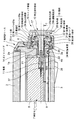
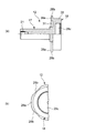
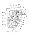
スイッチ装置10は、図1に示すように、腕時計ケース1の3時位置に設けられている。このスイッチ装置10は、図2に示すように、巻真11と、押圧操作部材12と、回転操作部材13と、ガイドパイプ14とを備えている。巻真11は、その内端部(図2では左端部)が時計モジュール7のハウジング8内に回転可能で且つスライド可能な状態で配置され、外端部(図2では右端部)がガイドパイプ14内に挿入されて押圧操作部材12に取り付けられるように構成されている。   As shown in FIG. 1, the switch device 10 is provided at the 3 o'clock position of the watch case 1. As shown in FIG. 2, the switch device 10 includes a winding stem 11, a pressing operation member 12, a rotation operation member 13, and a guide pipe 14. The winding stem 11 is disposed so that its inner end (left end in FIG. 2) is rotatable and slidable in the housing 8 of the timepiece module 7, and its outer end (right end in FIG. 2) is a guide pipe. It is configured to be inserted into 14 and attached to the pressing operation member 12.

押圧操作部材12は、図2に示すように、その内端部側(図2では左端部側)がガイドパイプ14内に挿入され、外端部側(図2では右端部側)が腕時計ケース1の外部に突出している。回転操作部材13は、腕時計ケース1の外部に突出した押圧操作部材12の外周部に、その軸方向に沿ってスライド可能で且つ押圧操作部材12と共に一体的に回転可能な状態で、取り付けられるように構成されている。   As shown in FIG. 2, the pressing member 12 has an inner end side (left end side in FIG. 2) inserted into the guide pipe 14 and an outer end side (right end side in FIG. 2) on the wristwatch case. 1 protrudes to the outside. The rotation operation member 13 is attached to the outer peripheral portion of the pressing operation member 12 protruding to the outside of the watch case 1 so as to be slidable along the axial direction and to be rotatable together with the pressing operation member 12. It is configured.

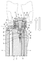
ガイドパイプ14は、図2および図3に示すように、腕時計ケース1の側壁部1a内にその内部と外部とに貫通するパイプ本体15と、このパイプ本体15の外周面に設けられて腕時計ケース1の側壁部1aの外面に当接するフランジ部16とを備えている。この場合、パイプ本体15は、その内側端部が腕時計ケース1の側壁部1aの内面から少し突出し、外側端部が腕時計ケース1の側壁部1aの外面から長く突出して形成されている。   2 and 3, the guide pipe 14 is provided in the side wall portion 1a of the watch case 1 so as to penetrate the inside and the outside of the side wall 1a, and on the outer peripheral surface of the pipe body 15. 1 and a flange portion 16 that contacts the outer surface of the side wall portion 1a. In this case, the pipe body 15 is formed so that its inner end protrudes slightly from the inner surface of the side wall 1 a of the watch case 1 and its outer end protrudes longer from the outer surface of the side wall 1 a of the watch case 1.

このガイドパイプ14のパイプ本体15内には、図2に示すように、押圧操作部材12の内端部側(図2では左端部側)が挿入されている。この押圧操作部材12は、図2および図5に示すように、その外径がパイプ本体15の内径とほぼ同じ大きさに形成された軸部17と、この軸部17の外端部(図2では右端部)に設けられて軸部17よりも大きい径の頭部18とを備えている。   As shown in FIG. 2, the inner end portion side (left end portion side in FIG. 2) of the pressing operation member 12 is inserted into the pipe body 15 of the guide pipe 14. As shown in FIGS. 2 and 5, the pressing operation member 12 has a shaft portion 17 having an outer diameter that is substantially the same as the inner diameter of the pipe body 15, and an outer end portion (see FIG. 2 is provided at the right end portion) and has a head 18 having a diameter larger than that of the shaft portion 17.

この押圧操作部材12の軸部17は、図2に示すように、防水性を確保するための一対の防水リング20を介してガイドパイプ14のパイプ本体15内にスライド可能で且つ回転可能な状態で取り付けられている。この場合、一対の防水リング20は、図3に示すように、ガイドパイプ14のパイプ本体15における内周面の外部側に埋め込まれた状態で設けられている。   As shown in FIG. 2, the shaft portion 17 of the pressing operation member 12 is slidable and rotatable in the pipe body 15 of the guide pipe 14 via a pair of waterproof rings 20 for ensuring waterproofness. It is attached with. In this case, as shown in FIG. 3, the pair of waterproof rings 20 is provided in a state of being embedded on the outer side of the inner peripheral surface of the pipe body 15 of the guide pipe 14.

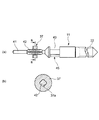
また、この押圧操作部材12の内端部には、図2に示すように、巻真11の外端部が連結されている。すなわち、押圧操作部材12の内端部には、図5(a)および図6(a)に示すように、ねじ穴21が軸方向に沿って設けられており、巻真11の外端部には、図4(a)に示すように、押圧操作部材12のねじ穴21に螺合するねじ部22が設けられている。   Further, the outer end portion of the winding stem 11 is connected to the inner end portion of the pressing operation member 12 as shown in FIG. That is, as shown in FIG. 5A and FIG. 6A, a screw hole 21 is provided in the inner end portion of the pressing operation member 12 along the axial direction. As shown in FIG. 4A, a screw portion 22 that is screwed into the screw hole 21 of the pressing operation member 12 is provided.

これにより、押圧操作部材12は、図2に示すように、軸部17の内端部のねじ穴21に巻真11の外端部のねじ部22が螺着することにより、ガイドパイプ14内において軸部17の内端部に巻真11の外端部が取り付けられ、この状態で巻真11と一体的に軸方向に沿ってスライドすると共に回転するように構成されている。   As a result, as shown in FIG. 2, the pressing operation member 12 is screwed into the screw hole 21 at the inner end portion of the shaft portion 17, and the screw portion 22 at the outer end portion of the winding stem 11 is screwed into the guide pipe 14. The outer end portion of the winding stem 11 is attached to the inner end portion of the shaft portion 17, and in this state, the winding stem 11 is configured to slide integrally with the winding stem 11 and rotate.

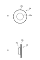
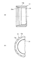
一方、回転操作部材13は、図2および図5に示すように、ほぼ円筒形状に形成され、その内部に腕時計ケース1の外部に位置する押圧操作部材12およびガイドパイプ14のフランジ部16が挿入するように構成されている。この回転操作部材13の外周面には、図8(a)および図8(b)に示すように、滑り止め用の溝部13aが円周方向に沿って等間隔で多数設けられている。   On the other hand, as shown in FIGS. 2 and 5, the rotation operation member 13 is formed in a substantially cylindrical shape, and the pressing operation member 12 located outside the watch case 1 and the flange portion 16 of the guide pipe 14 are inserted therein. Is configured to do. As shown in FIGS. 8A and 8B, a large number of anti-slip grooves 13a are provided on the outer peripheral surface of the rotation operation member 13 at equal intervals along the circumferential direction.

また、この回転操作部材13は、図2および図8に示すように、その内径がガイドパイプ14のフランジ部16の外径とほぼ同じ大きさの貫通孔23が軸方向に貫通して形成されている。この貫通孔23の外部側(図8(a)では右側)の開口には、図5および図8(a)に示すように、押圧操作部材12が貫通孔23から腕時計ケース1の外部側(図2では右側)に向けて抜け出すのを阻止する抜止め鍔部24が設けられている。   Further, as shown in FIGS. 2 and 8, the rotation operation member 13 is formed with a through hole 23 having an inner diameter that is substantially the same as the outer diameter of the flange portion 16 of the guide pipe 14 in the axial direction. ing. As shown in FIGS. 5 and 8A, the pressing operation member 12 is inserted into the opening on the outside side of the through hole 23 (on the right side in FIG. 8A) from the through hole 23 to the outside of the watch case 1 ( A retaining collar 24 is provided to prevent the slipping out toward the right side in FIG.

この抜止め鍔部24は、図2および図5(a)に示すように、押圧操作部材12の頭部18に設けられた後述するストッパ部28aが内側から当接することにより、押圧操作部材12が貫通孔23から腕時計ケース1の外部側(図5(a)では右側)に向けて抜け出さないように構成されている。   As shown in FIG. 2 and FIG. 5A, the retaining collar 24 is configured such that a stopper 28 a (described later) provided on the head 18 of the pressing operation member 12 comes into contact with the pressing operation member 12 from the inside. Is configured so as not to come out from the through hole 23 toward the outside of the watch case 1 (the right side in FIG. 5A).

また、この回転操作部材13は、図2に示すように、押圧操作部材12と共に押し込まれた状態で、ロック部25によってガイドパイプ14にロックされるように構成されている。すなわち、このロック部25は、図8(a)に示す回転操作部材13の貫通孔23における内部側(図8(a)では左側)に位置する開口の内周面に設けられた雌ねじ部25aと、図3に示すガイドパイプ14のフランジ部16の外周面に設けられた雄ねじ部25bとを備え、図2に示すように、ガイドパイプ14の雄ねじ部25bに回転操作部材13の雌ねじ部25aが着脱可能に螺合するように構成されている。   Further, as shown in FIG. 2, the rotation operation member 13 is configured to be locked to the guide pipe 14 by the lock portion 25 while being pushed together with the pressing operation member 12. That is, the lock portion 25 is a female screw portion 25a provided on the inner peripheral surface of the opening located on the inner side (left side in FIG. 8A) in the through hole 23 of the rotation operation member 13 shown in FIG. And a male screw portion 25b provided on the outer peripheral surface of the flange portion 16 of the guide pipe 14 shown in FIG. 3, and as shown in FIG. 2, the male screw portion 25b of the rotary operation member 13 is connected to the male screw portion 25b of the guide pipe 14. Is configured to be detachably screwed.

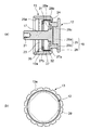
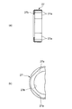
また、この回転操作部材13の貫通孔23内には、図5(a)に示すように、連動パイプ27が嵌め込まれている。この連動パイプ27は、回転操作部材13の回転を押圧操作部材12に伝達するためのものであり、回転操作部材13の貫通孔23内に固定されている。すなわち、この連動パイプ27は、その外径が回転操作部材13の貫通孔23の内径とほぼ同じ大きさに形成されている。   Further, as shown in FIG. 5A, an interlocking pipe 27 is fitted into the through hole 23 of the rotation operation member 13. The interlocking pipe 27 is for transmitting the rotation of the rotation operation member 13 to the pressing operation member 12, and is fixed in the through hole 23 of the rotation operation member 13. That is, the interlocking pipe 27 has an outer diameter that is substantially the same as the inner diameter of the through hole 23 of the rotation operation member 13.

また、この連動パイプ27は、図5(a)に示すように、その軸方向の長さが回転操作部材13のほぼ半分程度の長さに形成され、その内端部にリング状の鍔部27bが設けられた構成になっている。さらに、この連動パイプ27の内周面には、図9(a)および図9(b)に示すように、凹凸部27aが設けられている。これに伴って、押圧操作部材12の頭部18におけるストッパ部28aの外周面には、図6(b)に示すように、連動パイプ27の凹凸部27aに係合する後述する凹凸部28bが設けられている。   Further, as shown in FIG. 5 (a), the interlocking pipe 27 is formed so that its axial length is approximately half that of the rotation operation member 13, and a ring-shaped flange portion is formed at the inner end thereof. 27b is provided. Furthermore, as shown in FIG. 9A and FIG. 9B, an uneven portion 27 a is provided on the inner peripheral surface of the interlocking pipe 27. Along with this, on the outer peripheral surface of the stopper portion 28a in the head portion 18 of the pressing operation member 12, as shown in FIG. 6 (b), a concavo-convex portion 28b to be described later that engages with the concavo-convex portion 27a of the interlocking pipe 27 is provided. Is provided.

この場合、押圧操作部材12の頭部18は、図2および図5に示すように、回転操作部材13の抜止め鍔部24内に挿入して外部に向けて出没する突起部28と、この突起部28に取り付けられた操作部29とを有している。突起部28の外周面における内端部(図5(a)では左端部)には、図5および図6に示すように、回転操作部材13の抜止め鍔部24の内壁面に当接するストッパ部28aが設けられている。   In this case, as shown in FIGS. 2 and 5, the head portion 18 of the pressing operation member 12 is inserted into the retaining collar portion 24 of the rotation operation member 13, and the protruding portion 28 that protrudes and protrudes outward. And an operating portion 29 attached to the protruding portion 28. As shown in FIGS. 5 and 6, a stopper that abuts against the inner wall surface of the retaining collar portion 24 of the rotation operation member 13 is provided at the inner end portion (the left end portion in FIG. 5A) on the outer peripheral surface of the projection portion 28. A portion 28a is provided.

この突起部28におけるストッパ部28aの外周面には、図6(a)および図6(b)に示すように、連動パイプ27の凹凸部27aに係合する凹凸部28bが設けられている。これにより、突起部28は、その外周部の凹凸部28bが連動パイプ27の凹凸部27aに係合することにより、連動パイプ27内に軸方向に沿ってスライドすると共に、連動パイプ27と一体的に回転するように構成されている。   As shown in FIG. 6A and FIG. 6B, an uneven portion 28 b that engages with the uneven portion 27 a of the interlocking pipe 27 is provided on the outer peripheral surface of the stopper portion 28 a in the protruding portion 28. As a result, the projection 28 slides along the axial direction into the interlocking pipe 27 by engaging the recesses and protrusions 28b of the outer peripheral portion with the recesses and protrusions 27a of the interlocking pipe 27, and is integrated with the interlocking pipe 27. It is comprised so that it may rotate.

また、操作部29は、図5および図7に示すように、突起部28の外端面に取り付けられる取付凸部29aと、この取付凸部29aに設けられた連動突起部29bとを備えている。取付凸29aは、突起部28の外端面に設けられた取付凹部28cに圧入により嵌着固定されている。連動突起部29bは、押圧操作部材12が外部から押された際に、回転操作部材13の外端部に当接するものであり、回転操作部材13の外周部とほぼ同じ大きさか、それよりも少し小さい大きさに形成されている。   Further, as shown in FIGS. 5 and 7, the operation unit 29 includes an attachment projection 29 a attached to the outer end surface of the projection 28 and an interlocking projection 29 b provided on the attachment projection 29 a. . The mounting protrusion 29a is fitted and fixed to the mounting recess 28c provided on the outer end surface of the protrusion 28 by press fitting. The interlocking protrusion 29b comes into contact with the outer end of the rotation operation member 13 when the pressing operation member 12 is pressed from the outside, and is approximately the same size as the outer periphery of the rotation operation member 13 or larger than that. It is formed in a small size.

これにより、押圧操作部材12は、図2および図5に示すように、回転操作部材13の外部に露出した頭部18の操作部29が押圧操作されると、突起部28のストッパ部28aの凹凸部28bが連動パイプ27の凹凸部27aに係合した状態で、連動パイプ27内を軸方向に沿ってスライドするように構成されている。   Thereby, as shown in FIGS. 2 and 5, when the operation portion 29 of the head 18 exposed to the outside of the rotation operation member 13 is pressed, the pressing operation member 12 moves the stopper portion 28 a of the protrusion 28. The concave and convex portion 28b is configured to slide along the axial direction in the interlocking pipe 27 in a state where the concave and convex portion 28b is engaged with the concave and convex portion 27a of the interlocking pipe 27.

また、この押圧操作部材12は、図2および図5に示すように、回転操作部材13の回転操作に伴って連動パイプ27が回転すると、この連動パイプ27の凹凸部27aに突起部28のストッパ部28aの凹凸部28bが係合していることにより、空転することなく、連動パイプ27と共に一体的に回転するように構成されている。   Further, as shown in FIGS. 2 and 5, when the interlocking pipe 27 is rotated in accordance with the rotation operation of the rotation operating member 13, the pressing operation member 12 is provided with a stopper for the protrusion 28 on the uneven portion 27 a of the interlocking pipe 27. By engaging the concavo-convex portion 28b of the portion 28a, it is configured to rotate integrally with the interlocking pipe 27 without idling.

さらに、この押圧操作部材12は、図11に示すように、回転操作部材13が引き出され、この引き出された回転操作部材13を押し込んでロックする際に、回転操作部材13を摘む指が操作部29の連動突起部29bの外周部に当接して、この操作部29が押し込まれ、この状態で回転操作部材13と共に押し込まれるように構成されている。   Further, as shown in FIG. 11, the pressing operation member 12 is pulled out of the rotation operation member 13, and when the extracted rotation operation member 13 is pushed in and locked, the finger that grips the rotation operation member 13 is operated by the operation unit. The operation portion 29 is pushed in contact with the outer peripheral portion of the 29 interlocking projections 29b, and is pushed together with the rotary operation member 13 in this state.

ところで、この押圧操作部材12は、図2に示すように、第1コイルばね30によって回転操作部材13の貫通孔23における外端部側(図2では右側)の開口に向けて付勢されている。すなわち、この第1第1コイルばね30は、腕時計ケース1の外部に突出した押圧操作部材12の軸部17の外周に配置された状態で、押圧操作部材12の頭部18とガイドパイプ14のフランジ部16との間に配置されている。   By the way, as shown in FIG. 2, the pressing operation member 12 is urged toward the opening on the outer end side (right side in FIG. 2) in the through hole 23 of the rotation operation member 13 by the first coil spring 30. Yes. That is, the first first coil spring 30 is disposed on the outer periphery of the shaft portion 17 of the pressing operation member 12 protruding to the outside of the watch case 1, and the head 18 of the pressing operation member 12 and the guide pipe 14. It is arranged between the flange portion 16.

この場合、第1コイルばね30は、図2および図5に示すように、その内端部(図2では左端部)がガイドパイプ14のフランジ部16の外側面に当接し、外端部(図2では左端部)が押圧操作部材12の頭部18の内面に設けられた第1装着溝31内に第1滑り部材32を介して弾力的に挿入されるように構成されている。   In this case, as shown in FIGS. 2 and 5, the first coil spring 30 has an inner end portion (left end portion in FIG. 2) abutting against an outer surface of the flange portion 16 of the guide pipe 14, and an outer end portion ( The left end portion in FIG. 2 is configured to be elastically inserted through the first sliding member 32 into the first mounting groove 31 provided on the inner surface of the head 18 of the pressing operation member 12.

この第1コイルばね30は、図2および図5に示すように、押圧操作部材12の頭部18の内面に設けられた第1装着溝31によって、押圧操作部材12の頭部18とガイドパイプ14のフランジ部16との間における所定位置に規制されている。また、この第1滑り部材32は、円板状のワッシャーであり、フッ素系、ポリエチレン系などの表面摩擦抵抗が小さい滑り性を有する合成樹脂によって形成されている。   As shown in FIGS. 2 and 5, the first coil spring 30 is configured such that the head 18 and the guide pipe of the pressing operation member 12 are formed by a first mounting groove 31 provided on the inner surface of the head 18 of the pressing operation member 12. It is regulated at a predetermined position between the fourteen flange portions 16. The first sliding member 32 is a disc-shaped washer, and is made of a synthetic resin having a sliding property such as a fluorine-based or polyethylene-based surface frictional resistance.

これにより、押圧操作部材12は、図2に示すように、回転操作部材13の回転操作に伴って連動パイプ27が回転する際に、第1コイルばね30のばね力によって押圧操作部材12の頭部18が腕時計ケース1の外部側(図2では右側)に向けて付勢されていても、第1コイルばね30の外端部(図2では右端部)が第1滑り部材32に弾接した状態で、回転方向に沿って滑ることにより、連動パイプ27と共に円滑に回転するように構成されている。   Thereby, as shown in FIG. 2, when the interlocking pipe 27 rotates in accordance with the rotation operation of the rotation operation member 13, the pressing operation member 12 has the head of the pressing operation member 12 by the spring force of the first coil spring 30. Even if the portion 18 is biased toward the outside of the watch case 1 (right side in FIG. 2), the outer end portion (right end portion in FIG. 2) of the first coil spring 30 is elastically contacted with the first sliding member 32. In this state, it is configured to smoothly rotate together with the interlocking pipe 27 by sliding along the rotation direction.

また、回転操作部材13は、図2に示すように、第2コイルばね33によって腕時計ケース1の側壁部1aの外端部側(図2では右側)に向けて付勢されている。すなわち、この第2コイルばね33は、第1コイルばね30の外周に配置された状態で、連動パイプ27とガイドパイプ14のフランジ部16との間に配置されている。   Further, as shown in FIG. 2, the rotation operation member 13 is urged toward the outer end side (right side in FIG. 2) of the side wall 1 a of the watch case 1 by the second coil spring 33. That is, the second coil spring 33 is disposed between the interlocking pipe 27 and the flange portion 16 of the guide pipe 14 in a state of being disposed on the outer periphery of the first coil spring 30.

この場合、第2コイルばね33は、図2および図5に示すように、その内端部(図2では左端部)がガイドパイプ14のフランジ部16の外側面(図2では右側面)に設けられた第2装着溝34内に挿入され、外端部(図2では左端部)が連動パイプ27の内部側の端面に第2滑り部材35を介して弾接するように構成されている。   In this case, as shown in FIGS. 2 and 5, the second coil spring 33 has an inner end portion (left end portion in FIG. 2) on the outer side surface (right side surface in FIG. 2) of the flange portion 16 of the guide pipe 14. The outer end portion (left end portion in FIG. 2) is inserted into the provided second mounting groove 34 and is configured to elastically contact the inner end surface of the interlocking pipe 27 via the second sliding member 35.

この第2コイルばね33は、図2および図5に示すように、ガイドパイプ14のフランジ部16の外側面に設けられた第2装着溝34によって、連動パイプ27とガイドパイプ14のフランジ部16との間における所定位置に規制されている。この第2滑り部材35も、第1滑り部材32と同様、円板状のワッシャーであり、フッ素系、ポリエチレン系などの表面摩擦抵抗が小さい滑り性を有する合成樹脂によって形成されている。   As shown in FIGS. 2 and 5, the second coil spring 33 is connected to the interlocking pipe 27 and the flange portion 16 of the guide pipe 14 by a second mounting groove 34 provided on the outer surface of the flange portion 16 of the guide pipe 14. It is regulated at a predetermined position between. The second sliding member 35 is also a disk-shaped washer, like the first sliding member 32, and is made of a synthetic resin having a sliding property such as a fluorine-based or polyethylene-based surface friction resistance.

これにより、回転操作部材12は、図2に示すように、その回転操作に伴って雌ねじ部26がガイドパイプ14のフランジ部16に設けられた雄ねじ部25から螺脱すると、図11に示すように、第2コイルばね33のばね力によって連動パイプ27が押し出され、これに伴って押圧操作部材12と共に押し出されるように構成されている。   Accordingly, as shown in FIG. 2, when the internal thread portion 26 is unscrewed from the external thread portion 25 provided on the flange portion 16 of the guide pipe 14 as shown in FIG. In addition, the interlocking pipe 27 is pushed out by the spring force of the second coil spring 33 and is pushed together with the pressing operation member 12.

また、この回転操作部材12は、図11に示すように、回転操作に伴って回転する際に、第2コイルばね33のばね力によって連動パイプ27が腕時計ケース1の外部側(図11では右側)に向けて付勢されていても、第2コイルばね33の外端部(図11では右端部)が第2滑り部材35に弾接した状態で、回転方向に沿って滑ることにより、連動パイプ27と共に円滑に回転するように構成されている。   In addition, as shown in FIG. 11, when the rotation operation member 12 rotates in accordance with the rotation operation, the interlocking pipe 27 is moved to the outside of the watch case 1 by the spring force of the second coil spring 33 (the right side in FIG. 11). ), The outer end of the second coil spring 33 (the right end in FIG. 11) is elastically contacted with the second sliding member 35 to slide along the rotational direction. It is configured to rotate smoothly with the pipe 27.

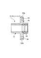
ところで、巻真11は、図2および図4に示すように、時計モジュール7のハウジング8内に配置された箇所の内部側(図2では左側)に磁石37が設けられ、この磁石37が巻真11と共に回転することにより、磁石37で発生した磁界の変化を磁気センサ38で検出するほか、図10に示すように、巻真11の軸方向のスライド位置が位置規制部材40によって規制されると共に、そのスライド位置に応じてスイッチが切り替わるように構成されている。   2 and 4, the winding stem 11 is provided with a magnet 37 on the inner side (left side in FIG. 2) of the portion disposed in the housing 8 of the timepiece module 7. By rotating together with the true 11, the magnetic sensor 38 detects a change in the magnetic field generated by the magnet 37, and the axial position of the winding stem 11 is restricted by the position restricting member 40 as shown in FIG. 10. At the same time, the switch is switched according to the slide position.

すなわち、ハウジング8内に位置する箇所の巻真11には、図2および図4に示すように、その内端部側(図2では左端部側)から順に、ガイド軸部41、スライド軸部42、係合溝部43が設けられている。ガイド軸部41は、ハウジング8内に設けられたガイド孔44内にスライド可能で、且つ回転可能な状態で配置されている。   That is, as shown in FIGS. 2 and 4, the winding stem 11 located in the housing 8 has a guide shaft portion 41 and a slide shaft portion in order from the inner end side (left end side in FIG. 2). 42, an engaging groove 43 is provided. The guide shaft part 41 is slidable and rotatable in a guide hole 44 provided in the housing 8.

スライド軸部42は、図4(a)および図4(b)に示すように、断面四角形状の角棒状に形成され、磁石37が軸方向に沿ってスライド可能に取り付けられていると共に、磁石37がスライド軸部42と共に一体的に回転するように構成されている。係合溝部43は、巻真11に設けられた環状の凹溝であり、位置規制部材40の後述するオシドリ45を巻真11のスライド動作に応じて回転させるように構成されている。   As shown in FIGS. 4A and 4B, the slide shaft portion 42 is formed in a square bar shape having a square cross section, and a magnet 37 is slidably attached along the axial direction. 37 is configured to rotate integrally with the slide shaft portion 42. The engaging groove portion 43 is an annular concave groove provided in the winding stem 11 and is configured to rotate a urchin 45 (described later) of the position regulating member 40 in accordance with the sliding operation of the winding stem 11.

磁石37は、図2および図4に示すように、その中心に四角形状の孔37aが設けられ、この孔37aに巻真11のスライド軸部42がスライド可能に挿入された状態で、ハウジング8によって軸方向への移動が規制されている。すなわち、この磁石37は、巻真11がスライドしても、スライド軸部42が磁石37に対してスライドすることにより、スライド軸部42の軸方向における位置がハウジング8によって規制されて常に所定位置で回転するように構成されている。   As shown in FIGS. 2 and 4, the magnet 37 is provided with a square hole 37a at the center thereof, and the housing 8 is slidably inserted into the hole 37a. Is restricted from moving in the axial direction. That is, even if the winding stem 11 is slid, the magnet 37 slides with respect to the magnet 37 so that the position of the slide shaft 42 in the axial direction is regulated by the housing 8 and is always at a predetermined position. It is configured to rotate at.

磁気センサ38は、図2に示すように、ハウジング8の下面に設けられた回路基板9の上面に磁石37と対応して設けられている。この磁気センサ38は、2つの磁気検出素子、例えば磁気抵抗素子(MR素子:Magneto Resistance 素子)と、その出力をデジタル化するICとを1つのパッケジに収めたものであり、2つの磁気抵抗素子で磁石37の回転に伴う磁界の変化を検出して、高い(ハイ:H)、低い(ロウ:L)の2種類の検出信号を出力するように構成されている。   As shown in FIG. 2, the magnetic sensor 38 is provided corresponding to the magnet 37 on the upper surface of the circuit board 9 provided on the lower surface of the housing 8. The magnetic sensor 38 includes two magnetic detection elements, for example, a magnetoresistive element (MR element: Magneto Resistance element) and an IC for digitizing the output of the magnetic sensor 38 in one package. Thus, a change in the magnetic field accompanying the rotation of the magnet 37 is detected, and two types of detection signals of high (high: H) and low (low: L) are output.

すなわち、この磁気センサ38は、2つの磁気抵抗素子の設置位置が異なっていることにより、磁石37の回転に伴う磁界の変化を検出した際に、出力に位相差が生じ、この位相差によって2種類の検出信号を出力することにより、磁石37の回転を検出するように構成されている。この場合、回路基板9に組み付けられたマイコン(図示せず)は、2種類の検出信号を解析して、磁石37の回転角度(回転量)を算出するように構成されている。   That is, the magnetic sensor 38 has a difference in the installation position of the two magnetoresistive elements, so that when the change in the magnetic field accompanying the rotation of the magnet 37 is detected, a phase difference occurs in the output. The rotation of the magnet 37 is detected by outputting a type of detection signal. In this case, a microcomputer (not shown) assembled on the circuit board 9 is configured to analyze two types of detection signals and calculate the rotation angle (rotation amount) of the magnet 37.

また、この磁気センサ38は、磁石37の回転方向(正回転であるか逆回転であるか)を検出すると共に、磁石37の正回転または逆回転が連続しているか否かをも検出する。これにより、回路基板9のマイコンは、磁気センサ38で検出された回転方向の検出信号により、指針を正方向(時計回り)または逆方向(反時計回り)に回転させると共に、磁気センサ38で検出された磁石37の回転が連続しているか否かの検出信号により、回転が連続している場合に、指針を早送りで正方向(時計回り)または逆方向(反時計回り)に回転させる。   The magnetic sensor 38 also detects the direction of rotation of the magnet 37 (whether it is forward rotation or reverse rotation) and also detects whether forward rotation or reverse rotation of the magnet 37 is continuous. As a result, the microcomputer of the circuit board 9 rotates the pointer in the forward direction (clockwise) or the reverse direction (counterclockwise) based on the rotation direction detection signal detected by the magnetic sensor 38 and detects it by the magnetic sensor 38. If the rotation of the magnet 37 is continued, the pointer is rotated in the forward direction (clockwise) or the reverse direction (counterclockwise) when the rotation continues.

一方、巻真11を位置規制する位置規制部材40は、図10に示すように、オシドリ45、オシドリばね46、スイッチ板47、および押え板48を備えている。オシドリ45は、図10に示すように、平板状に形成され、ハウジング8に回転可能に取り付けられ、巻真11の軸方向への移動に応じて回転するように構成されている。すなわち、このオシドリ45は、ハウジング8に起立して設けられた支持軸50にハウジング8の面方向に回転可能に取り付けられている。   On the other hand, as shown in FIG. 10, the position restricting member 40 that restricts the position of the winding stem 11 includes a mandarin duck 45, a duck spring 46, a switch plate 47, and a presser plate 48. As shown in FIG. 10, the mandarin orange 45 is formed in a flat plate shape, is rotatably attached to the housing 8, and is configured to rotate in accordance with the movement of the winding stem 11 in the axial direction. That is, the mandarin duck 45 is attached to a support shaft 50 provided upright on the housing 8 so as to be rotatable in the surface direction of the housing 8.

このオシドリ45には、図10に示すように、巻真11の係合溝部43内に配置される連動アーム部45aと、オシドリばね46によって弾力的に位置規制される連動ピン45bと、スイッチ板47をオシドリ45と共に回転させる連結ピン45cとが設けられている。これにより、オシドリ45は、図10に示すように、巻真11が軸方向に移動すると、巻真11の係合溝部43の移動に伴って連動アーム部45aが揺動することにより、支持軸50を中心に回転するように構成されている。   As shown in FIG. 10, the mandarin orange 45 includes an interlocking arm portion 45 a disposed in the engaging groove portion 43 of the winding stem 11, an interlocking pin 45 b that is elastically regulated by a shorebird spring 46, and a switch plate. A connecting pin 45c that rotates 47 together with the shoreline 45 is provided. Thereby, as shown in FIG. 10, when the winding stem 11 moves in the axial direction, the shorebird 45 swings the interlocking arm portion 45a along with the movement of the engaging groove portion 43 of the winding stem 11, so that the supporting shaft It is configured to rotate about 50.

オシドリばね46は、図10に示すように、板ばねであり、オシドリ45の近傍に位置する箇所のハウジング8に固定され、オシドリ45の連動ピン45bを弾力的に保持して位置規制することにより、オシドリ45の回動位置を弾力的に規制して巻真11の軸方向の移動位置を規制するように構成されている。すなわち、このオシドリばね46は、図10に示すように、その先端部にオシドリ45の連動ピン45bを弾力的に保持する位置規制部51が設けられている。   As shown in FIG. 10, the mandarin spring 46 is a leaf spring, is fixed to the housing 8 at a location located in the vicinity of the mandarin duck 45, and elastically holds the interlocking pin 45 b of the mandarin duck 45 to restrict the position. The rotation position of the mandarin duck 45 is elastically restricted to restrict the movement position of the winding stem 11 in the axial direction. That is, as shown in FIG. 10, the mandarin spring 46 is provided with a position restricting portion 51 that elastically holds the interlocking pin 45 b of the mandarin duck 45 at the tip portion thereof.

この位置規制部51には、図10に示すように、連動ピン45bを弾力的に係止する複数の係止凹部51aが設けられている。これにより、オシドリばね46は、図10に示すように、巻真11が押し込まれた第1の位置(通常運針状態)のときに、オシドリ45の連動ピン45bを位置規制部51のいずれかの係止凹部51aで弾力的に係止することにより、巻真11を第1の位置に規制するように構成されている。   As shown in FIG. 10, the position restricting portion 51 is provided with a plurality of locking recesses 51a for elastically locking the interlocking pin 45b. Thereby, as shown in FIG. 10, when the winding spring 11 is in the first position where the winding stem 11 is pushed (normally in the state of hand movement), the interlocking pin 45 b of the mandarin duck 45 is moved to any one of the position restricting portions 51. The winding stem 11 is configured to be restricted to the first position by being elastically locked by the locking recess 51a.

また、このオシドリばね46は、図12に示すように、巻真11が軸方向に引き出された第2の位置(時刻修正状態の位置)に移動するときに、オシドリ45が回転し、その回転に伴って連動ピン45bが回転移動して位置規制部51を弾性変形させ、この弾性変形した位置規制部51のいずれかの係止凹部51aがオシドリ45の連動ピン45bを弾力的に係止することにより、巻真11を第2の位置に規制するように構成されている。   In addition, as shown in FIG. 12, when the winding stem 11 moves to the second position where the winding stem 11 is pulled out in the axial direction (the position in the time correction state), the shoreline spring 45 rotates, Accordingly, the interlocking pin 45b rotates and elastically deforms the position restricting portion 51, and any of the locking recesses 51a of the elastically deformed position restricting portion 51 elastically locks the interlocking pin 45b of the duck 45. Thus, the winding stem 11 is configured to be restricted to the second position.

さらに、このオシドリばね46は、図10に示すように、巻真11が押し込まれた第1の位置(通常運針状態)から、図13に示すように、巻真11が更に押し込まれた第3の位置(他の機能状態)に移動する際に、オシドリ45の回転に伴って連動ピン45bが回転移動して位置規制部51を弾性変形させ、この弾性変形した位置規制部51がオシドリ45の連動ピン45bを弾力的に係止することにより、巻真11を第3の位置に規制するように構成されている。   Further, as shown in FIG. 10, the horseshoe spring 46 has a third position where the winding stem 11 is further pushed in, as shown in FIG. 13, from the first position where the winding stem 11 is pushed in (normal hand movement state). When moving to the position (other functional states), the interlocking pin 45 b rotates and moves with the rotation of the mandarin duck 45 to elastically deform the position restricting portion 51, and the elastically deformed position restricting portion 51 is It is configured to restrict the winding stem 11 to the third position by elastically locking the interlocking pin 45b.

スイッチ板47は、金属板からなり、図10に示すように、オシドリ45と共に支持軸50に回転可能に取り付けられている。このスイッチ板47には、図10に示すように、回路基板9の上面に接触して摺動する接触ばね部47aが、オシドリ45の連動アーム部45aと反対側に向けて延設されている。このスイッチ板47の所定箇所には、オシドリ45の連結ピン45cが挿入されている。   The switch plate 47 is made of a metal plate and is rotatably attached to the support shaft 50 together with the urchin 45 as shown in FIG. As shown in FIG. 10, a contact spring portion 47 a that slides in contact with the upper surface of the circuit board 9 is extended on the switch plate 47 toward the opposite side to the interlocking arm portion 45 a of the duck 45. . A connecting pin 45 c of the mandarin duck 45 is inserted into a predetermined portion of the switch plate 47.

これにより、スイッチ板47は、図10に示すように、接触ばね部47aの先端部が回路基板9の上面に接触した状態で、オシドリ45と共に回転移動し、この接触ばね部47aの先端部が回路基板9の上面に設けられた接点部9a、9bのいずれかに接触することにより、接触位置が切り替わるように構成されている。   Thereby, as shown in FIG. 10, the switch plate 47 rotates and moves together with the duck 45 with the tip of the contact spring 47a in contact with the upper surface of the circuit board 9, and the tip of the contact spring 47a The contact position is switched by contacting any one of the contact portions 9 a and 9 b provided on the upper surface of the circuit board 9.

すなわち、このスイッチ板47は、図10に示すように、巻真11が第1の位置(通常運針状態)に押し込まれてオシドリ45が回転したときに、このオシドリ45と共に回転移動し、接触ばね部47aが回路基板9の上面に設けられた接点部9a、9b間に位置して、その接点部9a、9bのいずれにも接触しないことにより、通常運針モードを維持するように構成されている。   That is, as shown in FIG. 10, when the winding stem 11 is pushed into the first position (normal hand movement state) and the urchin 45 is rotated, the switch plate 47 rotates together with the urchin 45, and the contact spring. The portion 47a is located between the contact portions 9a and 9b provided on the upper surface of the circuit board 9, and is configured to maintain the normal hand movement mode by not contacting any of the contact portions 9a and 9b. .

また、このスイッチ板47は、図12に示すように、巻真11が第2の位置(時刻修正状態)に引き出されてオシドリ45が回転したときに、このオシドリ45と共に回転移動し、接触ばね部47aが回路基板9の上面に設けられた1つの接点部9aに接触することにより、通常運針モードから時刻修正モードに切り替えるように構成されている。   Further, as shown in FIG. 12, when the winding stem 11 is pulled out to the second position (time correction state) and the mandarin orange 45 rotates, the switch plate 47 rotates together with the mandarin orange 45, and the contact spring. When the portion 47a contacts one contact portion 9a provided on the upper surface of the circuit board 9, the normal hand movement mode is switched to the time adjustment mode.

さらに、このスイッチ板47は、図13に示すように、巻真11が第3の位置(他の機能状態)に押し込まれてオシドリ45が回転したときに、このオシドリ45と共に回転移動し、接触ばね部47aが回路基板9の上面に設けられた他の接点部9bに接触することにより、通常運針モードから他の機能モードに切り替えるように構成されている。   Further, as shown in FIG. 13, when the winding stem 11 is pushed into the third position (other functional state) and the mandarin duck 45 rotates, the switch plate 47 rotates and moves together with the mandarin duck 45. The spring portion 47a is configured to switch from the normal hand movement mode to another function mode by contacting another contact portion 9b provided on the upper surface of the circuit board 9.

なお、押え板48は、図10に示すように、オシドリばね46と共にハウジング8にねじ48aによって取り付けられて、オシドリばね46およびスイッチ板47を押え付けることにより、オシドリ45をハウジング8に対して回転可能な状態で押えるように構成されている。   As shown in FIG. 10, the presser plate 48 is attached to the housing 8 together with the mandarin spring 46 by a screw 48 a, and the urchin 45 is rotated with respect to the housing 8 by pressing the urchin spring 46 and the switch plate 47. It is configured so that it can be pressed in a possible state.

次に、この電子腕時計におけるスイッチ装置10の作用について説明する。
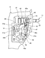
まず、スイッチ装置10の回転操作部材13を操作しない通常運針状態について説明する。この通常運針状態では、図2に示すように、回転操作部材13が腕時計ケース1内に向けて押し込まれてロック部25によってガイドパイプ14にロックされている。すなわち、この回転操作部材13は、その雌ねじ部25aがガイドパイプ14の雄ねじ部25bに螺着してロックされている。
Next, the operation of the switch device 10 in this electronic wristwatch will be described.
First, a normal hand movement state in which the rotation operation member 13 of the switch device 10 is not operated will be described. In this normal hand movement state, as shown in FIG. 2, the rotation operation member 13 is pushed into the wristwatch case 1 and locked to the guide pipe 14 by the lock portion 25. In other words, the rotary operation member 13 is locked by locking the female screw portion 25 a to the male screw portion 25 b of the guide pipe 14.

このため、回転操作部材13は、図2に示すように、その内部に設けられた連動パイプ27のリング状の鍔部27bが第2滑り部材35を介して第2コイルばね33を圧縮させた状態で、腕時計ケース1の内部側に向けて押し込まれている。この状態では、回転操作部材13の抜止め鍔部24が押圧操作部材12の頭部18に設けられた突起部28のストッパ部28aに外側から当接していることにより、押圧操作部材12が腕時計ケース1の内部側に向けて押し込まれている。   Therefore, as shown in FIG. 2, the rotation operation member 13 has the ring-shaped flange portion 27 b of the interlocking pipe 27 provided therein compressed the second coil spring 33 via the second sliding member 35. In the state, it is pushed toward the inside of the watch case 1. In this state, the retaining member 24 of the rotation operation member 13 is in contact with the stopper portion 28a of the projection 28 provided on the head 18 of the pressing operation member 12 from the outside, so that the pressing operation member 12 is It is pushed toward the inside of the case 1.

すなわち、この押圧操作部材12は、図2に示すように、その頭部18が第1滑り部材32を介して第1コイルばね30を圧縮させた状態で、腕時計ケース1の内部側に向けて押し込まれている。このため、押圧操作部材12は、その軸部17がガイドパイプ14内における腕時計ケース1の内部側に向けて押し込まれている。   That is, as shown in FIG. 2, the pressing operation member 12 is directed toward the inner side of the wristwatch case 1 with the head 18 compressing the first coil spring 30 via the first sliding member 32. It is pushed in. Therefore, the shaft portion 17 of the pressing operation member 12 is pressed toward the inside of the watch case 1 in the guide pipe 14.

また、この状態では、図10に示すように、巻真11が位置規制部材40のオシドリ45によって第1の位置(通常運針状態)に位置規制されていると共に、この位置規制部材40のスイッチ板47が回路基板9の接点部9a、9b間に位置して、そのいずれも接触しないオフ状態になっている。   Further, in this state, as shown in FIG. 10, the winding stem 11 is position-restricted to the first position (normal hand movement state) by the urchin 45 of the position-restricting member 40, and the switch plate of the position-restricting member 40 47 is located between the contact portions 9a and 9b of the circuit board 9 and is in an off state in which neither of them contacts.

次に、巻真11を回転させて時刻を修正する場合について説明する。
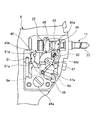
この場合には、まず、図11に示すように、回転操作部材13を回転させてガイドパイプ14に対する回転操作部材13のロックを解除する。すなわち、回転操作部材13を回転させると、ガイドパイプ14のフランジ部16の雄ねじ部25bに対する回転操作部材13の雌ねじ部25aの螺着が解除される。
Next, a case where the winding stem 11 is rotated to correct the time will be described.
In this case, first, as shown in FIG. 11, the rotation operation member 13 is rotated to unlock the rotation operation member 13 with respect to the guide pipe 14. That is, when the rotation operation member 13 is rotated, the screwing of the female screw portion 25a of the rotation operation member 13 with respect to the male screw portion 25b of the flange portion 16 of the guide pipe 14 is released.

このときには、回転操作部材13がそのロックを解除する回転操作に伴って腕時計ケース1から離れる方向(図11では右側)に移動すると共に、第2コイルばね33のばね力によって押し出される。また、このときには、回転操作部材13の移動に伴って押圧操作部材12が第1コイルばね30のばね力によっても押し出されることにより、回転操作部材13と同じ方向にスライドする。   At this time, the rotation operation member 13 moves away from the wristwatch case 1 (right side in FIG. 11) in accordance with the rotation operation for releasing the lock, and is pushed out by the spring force of the second coil spring 33. At this time, the pressing operation member 12 is also pushed by the spring force of the first coil spring 30 as the rotation operation member 13 moves, and slides in the same direction as the rotation operation member 13.

また、このときには、押圧操作部材12の軸部17に設けられたねじ穴21に巻真11のねじ部22が螺合して、押圧操作部材12に巻真11が連結されていることにより、押圧操作部材12のスライド動作に伴って巻真11が引き出される方向にスライドする。すると、図12に示すように、巻真11の係合溝部43に係合している位置規制部材40のオシドリ45が、巻真11のスライドに伴って回転し、スイッチ板47を回転させて、スイッチ板47の接触ばね部45aを1つの接点部9aに接触させる。   At this time, the screw portion 22 of the winding stem 11 is screwed into the screw hole 21 provided in the shaft portion 17 of the pressing operation member 12, and the winding stem 11 is connected to the pressing operation member 12. As the pressing operation member 12 slides, the winding stem 11 slides in the direction in which it is pulled out. Then, as shown in FIG. 12, the shoreline 45 of the position restricting member 40 engaged with the engaging groove 43 of the winding stem 11 rotates with the slide of the winding stem 11 to rotate the switch plate 47. The contact spring portion 45a of the switch plate 47 is brought into contact with one contact portion 9a.

これにより、スイッチがオン状態になり、モードが通常運針モードから時刻修正モードに切り替わる。このため、磁気センサ38がオンして巻真11に設けられた磁石37の磁界を検出可能な状態になる。この状態で、回転操作部材13を回転させると、これに伴って押圧操作部材12が回転し、この押圧操作部材12の回転が巻真11に伝達され、この巻真11が押圧操作部材12と共に回転する。すると、巻真11と共に磁石37が回転するので、この磁石37の回転に伴う磁界の変化を磁気センサ38で検出し、その検出結果に基づいて指針を運針させて時刻を修正する。   As a result, the switch is turned on, and the mode is switched from the normal hand movement mode to the time adjustment mode. For this reason, the magnetic sensor 38 is turned on, and the magnetic field of the magnet 37 provided on the winding stem 11 can be detected. When the rotation operation member 13 is rotated in this state, the pressing operation member 12 is rotated accordingly, and the rotation of the pressing operation member 12 is transmitted to the winding stem 11, and the winding stem 11 is combined with the pressing operation member 12. Rotate. Then, since the magnet 37 rotates together with the winding stem 11, a change in the magnetic field accompanying the rotation of the magnet 37 is detected by the magnetic sensor 38, and the pointer is moved based on the detection result to correct the time.

この状態のときに、押圧操作部材12を外部から押圧操作しても、スイッチがオフ状態になるだけで、モードが切り替わることはない。すなわち、押圧操作部材12を第1コイルばね30のばね力に抗して押圧操作すると、これに伴って巻真11が押し込まれる方向にスライドする。すると、図10に示すように、巻真11の係合溝部43に係合している位置規制部材40のオシドリ45が、巻真11のスライドに伴って回転し、スイッチ板47を回転させる。このため、図10に示すように、スイッチ板47の接触ばね部45aが回路基板9の接点部9a、9b間に移動し、そのいずれにも接触しないオフ状態になり、モードが切り替わることはない。   In this state, even if the pressing member 12 is pressed from the outside, the switch is simply turned off and the mode is not switched. That is, when the pressing operation member 12 is pressed against the spring force of the first coil spring 30, the winding stem 11 is slid in the direction in which it is pushed. Then, as shown in FIG. 10, the shoreline 45 of the position restricting member 40 engaged with the engagement groove 43 of the winding stem 11 rotates with the slide of the winding stem 11 to rotate the switch plate 47. For this reason, as shown in FIG. 10, the contact spring part 45a of the switch board 47 moves between the contact parts 9a and 9b of the circuit board 9, and it will be in the OFF state which does not contact any of them, and a mode will not switch. .

このように時刻を修正した後には、スイッチ装置10の回転操作部材13を再び押し込んで通常運針状態に戻し、回転操作部材13が操作できない通常運針状態にロックする。この場合、図11に示す状態で、回転操作部材13を腕時計ケース1側に押し込む際には、指先が押圧操作部材13の頭部18における操作部29の連動突起部29bに当接し、この連動突起部29bを押しながら回転操作部材13が腕時計ケース1側に押し込まれる。   After correcting the time in this way, the rotation operation member 13 of the switch device 10 is pushed again to return to the normal hand movement state, and the rotation operation member 13 is locked to the normal hand movement state where the rotation operation member 13 cannot be operated. In this case, when the rotary operation member 13 is pushed into the wristwatch case 1 in the state shown in FIG. 11, the fingertip comes into contact with the interlocking protrusion 29 b of the operation portion 29 in the head 18 of the pressing operation member 13. The rotation operation member 13 is pushed into the watch case 1 side while pushing the projection 29b.

このときには、連動突起部29bが押されることにより、巻真11の係合溝部43に係合している位置規制部材40のオシドリ45が、巻真11のスライドに伴って回転し、スイッチ板47を回転させ、図10に示すように、スイッチ板47の接触ばね部45aが回路基板9の接点部9a、9b間に移動し、そのいずれにも接触しないオフ状態になる。このため、誤って回転操作部材13を回転させても、磁気センサ38が磁石37の回転に伴う磁界の変化を検出することがないので、誤動作を起すことがない。   At this time, when the interlocking projection 29b is pushed, the urchin 45 of the position restricting member 40 engaged with the engaging groove 43 of the winding stem 11 rotates as the winding stem 11 slides, and the switch plate 47 As shown in FIG. 10, the contact spring portion 45 a of the switch plate 47 moves between the contact portions 9 a and 9 b of the circuit board 9 and enters an off state where it does not contact any of them. For this reason, even if the rotation operation member 13 is rotated by mistake, the magnetic sensor 38 does not detect a change in the magnetic field accompanying the rotation of the magnet 37, so that no malfunction occurs.

次に、このスイッチ装置10の押圧操作部材12を押圧操作して他の機能に切り替える場合について説明する。
この場合には、図2に示したように、スイッチ装置10の回転操作部材13が操作できない通常運針状態にロックし、図10に示すように、スイッチ板47の接触ばね部45aが回路基板9の接点部9a、9b間に移動し、そのいずれにも接触しないオフ状態、つまり通常運針状態にする。
Next, a case where the pressing operation member 12 of the switch device 10 is pressed to switch to another function will be described.
In this case, as shown in FIG. 2, the rotation operation member 13 of the switch device 10 is locked in a normal operating state where the operation cannot be performed, and as shown in FIG. 10, the contact spring portion 45 a of the switch plate 47 is connected to the circuit board 9. Are moved between the contact portions 9a and 9b and brought into an off state in which neither of them is in contact, that is, a normal hand movement state.

このような通常運針状態において、押圧操作部材12が外部から押圧操作されると、図2に示す押圧操作部材12が第1コイルばね30のばね力に抗して腕時計ケース1の内部側(図2では左側)に向けてスライドし、この押圧操作部材12のスライドに伴って巻真11が押し込まれる。このときには、図13に示すように、巻真11の係合溝部43に係合している位置規制部材40のオシドリ45が、巻真11のスライドに伴って回転し、スイッチ板47を回転させる。このため、スイッチ板47の接触ばね部47aが他の接点部9bに接触してオン状態になり、スイッチが通常運針モードから他の機能モードに切り替わる。   In such a normal hand movement state, when the pressing operation member 12 is pressed from the outside, the pressing operation member 12 shown in FIG. 2 resists the spring force of the first coil spring 30 to the inner side of the watch case 1 (see FIG. 2 to the left), and the winding stem 11 is pushed in as the pressing operation member 12 slides. At this time, as shown in FIG. 13, the urchin 45 of the position restricting member 40 engaged with the engaging groove 43 of the winding stem 11 rotates with the slide of the winding stem 11 to rotate the switch plate 47. . For this reason, the contact spring portion 47a of the switch plate 47 comes into contact with the other contact portion 9b to be turned on, and the switch is switched from the normal hand movement mode to another function mode.

このように、この電子腕時計のスイッチ装置10によれば、軸方向に貫通孔23が形成された回転操作部材13と、この回転操作部材13の貫通孔23内に移動可能で、貫通孔23の一方の開口から押圧操作可能で、且つ貫通孔23の一方の開口から抜け出さないように設けられていると共に、回転操作部材13を回転させた際に回転操作部材13と共に一体的に回転する押圧操作部材12と、回転操作部材13の貫通孔23内に配置され、少なくとも押圧操作部材12を一方の開口方向に向けて付勢する第1コイルばね30とを備え、押圧操作部材12は、回転操作部材13の貫通孔23の一方の開口から外部に出没可能に突出し、この突出した外端部に貫通孔23の内径よりも大きく形成された操作部29を有しているので、スイッチの操作性が良く、且つスイッチ操作時における誤動作を防ぐことができる。   As described above, according to the switch device 10 of the electronic wristwatch, the rotation operation member 13 having the through hole 23 formed in the axial direction and the movement of the rotation operation member 13 into the through hole 23 can be achieved. A pressing operation that can be pressed from one opening and is provided so as not to come out from the one opening of the through-hole 23 and that rotates together with the rotating operation member 13 when the rotating operation member 13 is rotated. The member 12 and a first coil spring 30 disposed in the through hole 23 of the rotation operation member 13 and biasing at least the pressure operation member 12 in one opening direction are provided. Since it protrudes to the outside from one opening of the through hole 23 of the member 13 and has an operation portion 29 formed larger than the inner diameter of the through hole 23 at the protruding outer end portion, Good work property, and it is possible to prevent malfunction during switch operation.

すなわち、このスイッチ装置10では、回転操作部材13を押し込んだ状態で押圧操作部材12の操作部29を押圧操作する際に、その押圧面積を広くすることができるので、確実に且つ良好に操作部29を押圧操作することができる。また、回転操作部材13を引き出して回転させた後、再び回転操作部材13を押し込む際には、回転操作部材1と同時に操作部29を押し込んでスイッチをオフ状態にすることができるので、回転操作部材13を押し込むときに誤って回転させても、スイッチが誤動作するのを確実に防ぐことができる。   That is, in this switch device 10, when the operating portion 29 of the pressing operation member 12 is pressed and operated with the rotation operating member 13 being pushed in, the pressing area can be increased, so that the operating portion can be reliably and satisfactorily improved. 29 can be pressed. Further, when the rotary operation member 13 is pulled out and rotated and then pushed in again, the operation unit 29 can be pushed in simultaneously with the rotary operation member 1 to turn off the switch. Even if the member 13 is accidentally rotated when the member 13 is pushed in, it is possible to reliably prevent the switch from malfunctioning.

この場合、押圧操作部材12の操作部29は、その外径が回転操作部材13の外径とほぼ同じ大きさの連動突起部29bを有しているので、回転操作部材13を引き出して回転させた後、再び回転操作部材13を指で摘んで押し込む際に、回転操作部材13を摘んだ指が自然に操作部29の連動突起部29bを摘んで押し込むことになり、このときに押圧操作部材12をスライドさせてスイッチをオフ状態にすることができる。このため、回転操作部材13を押し込むときに誤って回転させても、スイッチが誤動作するのを確実に防ぐことができる。   In this case, since the operation portion 29 of the pressing operation member 12 has the interlocking protrusion 29b whose outer diameter is substantially the same as the outer diameter of the rotation operation member 13, the rotation operation member 13 is pulled out and rotated. After that, when the rotary operation member 13 is picked and pushed again, the finger holding the rotary operation member 13 naturally picks and pushes the interlocking protrusion 29b of the operation unit 29. At this time, the pressing operation member The switch can be turned off by sliding 12. For this reason, even if it rotates accidentally when pushing in the rotation operation member 13, it can prevent reliably that a switch malfunctions.

また、このスイッチ装置10では、押圧操作部材12を貫通孔23の一方の開口方向に向けて付勢する第1コイルばね30と、回転操作部材13を貫通孔23の一方の開口方向に向けて付勢する第2コイルばね33とを備えていることにより、回転操作部材13を引き出して回転させる際に、第2コイルばね33のばね力によって回転操作部材13を安定して保持した状態で回転させることができると共に、第1コイルばね30のばね力によって押圧操作部材12を安定して保持した状態で連動させて回転させることができる。このため、スイッチ操作時にガタツキがなく、安定した状態でスイッチ動作することができ、これにより円滑に且つ良好にスイッチ操作ができるので、スイッチ操作性の向上を図ることができる。   Further, in this switch device 10, the first coil spring 30 that biases the pressing operation member 12 toward one opening direction of the through hole 23 and the rotation operation member 13 toward one opening direction of the through hole 23. By providing the second coil spring 33 to be urged, when the rotation operation member 13 is pulled out and rotated, the rotation operation member 13 is stably rotated by the spring force of the second coil spring 33. In addition, the pressing operation member 12 can be rotated in conjunction with the pressing operation member 12 in a stable state by the spring force of the first coil spring 30. For this reason, there is no backlash at the time of switch operation, and switch operation can be performed in a stable state. As a result, switch operation can be performed smoothly and satisfactorily, so that the switch operability can be improved.

また、このスイッチ装置10によれば、回転操作部材13と押圧操作部材12とを連動させる連動パイプ27を備え、この連動パイプ27は、押圧操作部材12が第1コイルばね30のばね力によって押し出された状態のときに回転操作部材13の回転操作に応じて押圧操作部材12を連動させて回転させ、この状態で押圧操作部材12が第1コイルばね30のばね力に抗して押圧操作された際に、この押圧操作部材12をスライドさせる構成であるから、スイッチ操作性が良い。   Further, according to the switch device 10, the interlocking pipe 27 that interlocks the rotation operation member 13 and the pressing operation member 12 is provided. The interlocking pipe 27 is pushed out by the pressing force of the first coil spring 30. In this state, the pressing operation member 12 is rotated in conjunction with the rotation operation of the rotation operating member 13, and in this state, the pressing operation member 12 is pressed against the spring force of the first coil spring 30. In this case, since the pressing operation member 12 is slid, the switch operability is good.

すなわち、この連動パイプ27は、回転操作部材13を引き出した状態で、回転操作部材13を回転操作すると、回転操作部材13の凹凸部27aと押圧操作部材12の凹凸部28bとが係合していることにより、その回転を押圧操作部材12に伝達して、この押圧操作部材12を確実に且つ良好に回転させることができる。また、この状態で押圧操作部材12を押圧操作すると、回転操作部材13の凹凸部27aと押圧操作部材12の凹凸部28bとが係合していることにより、第1コイルばね30のばね力に抗して押圧操作部材12を円滑にスライドさせて確実に且つ良好に押し込むことができる。   That is, when the rotation operation member 13 is rotated while the rotation operation member 13 is pulled out, the interlocking pipe 27 engages the uneven portion 27 a of the rotation operation member 13 and the uneven portion 28 b of the pressing operation member 12. Therefore, the rotation can be transmitted to the pressing operation member 12, and the pressing operation member 12 can be reliably and satisfactorily rotated. Further, when the pressing operation member 12 is pressed in this state, the unevenness portion 27 a of the rotation operation member 13 and the unevenness portion 28 b of the pressing operation member 12 are engaged with each other. Accordingly, the pressing operation member 12 can be smoothly slid by being smoothly slid.

さらに、このスイッチ装置10によれば、回転操作部材13を押圧操作部材12と共に第1、第2の各コイルばね30、33のばね力に抗して押し込んだ状態で、回転操作部材13をロックするロック部25を備えているので、通常の運針状態のときに、不用意にスイッチ動作するのを確実に防ぐことができる。   Furthermore, according to the switch device 10, the rotation operation member 13 is locked in a state where the rotation operation member 13 is pushed together with the pressing operation member 12 against the spring force of the first and second coil springs 30 and 33. Since the locking portion 25 is provided, it is possible to reliably prevent an inadvertent switch operation in a normal hand movement state.

すなわち、このロック部25は、腕時計ケース1の側壁部1aに設けられたガイドパイプ14のフランジ部16の外周部に設けられた雄ねじ部25bと、回転操作部材13の貫通孔23の毎週面に設けられた雌ねじ部25aとを備えた構成であるから、回転操作部材13を回転させて雌ねじ部25aをガイドパイプ14のフランジ部16の雄ねじ部25bに螺合させて締め付けることにより、回転操作部材13を腕時計ケース1に対して確実に且つ良好に固定してロックすることができる。   That is, the lock portion 25 is provided on the weekly surface of the male screw portion 25 b provided on the outer peripheral portion of the flange portion 16 of the guide pipe 14 provided on the side wall portion 1 a of the watch case 1 and the through hole 23 of the rotation operation member 13. Since the rotation operation member 13 is rotated and the female screw portion 25a is screwed into the male screw portion 25b of the flange portion 16 of the guide pipe 14 and tightened, the rotation operation member 13 is provided. 13 can be securely and satisfactorily fixed and locked to the watch case 1.

なお、上述した実施形態では、押圧操作部材12の操作部29が、回転操作部材の外径とほぼ同じ大きさに形成された円板状の連動突起部29bを備えている場合について述べたが、必ずしも連動突起部29bは円板状に形成されている必要はなく、円板状の外周部に鍔部を筒状に形成したものでも良く、要は回転操作部材13を指で摘むときにその指が当接して押圧操作部材12を押し込む形状であれば、どのような形状であっても良い。   In the above-described embodiment, the case where the operation portion 29 of the pressing operation member 12 includes the disk-like interlocking protrusion portion 29b formed to have substantially the same size as the outer diameter of the rotation operation member has been described. The interlocking protrusion 29b does not necessarily have to be formed in a disc shape, and may be a disc-shaped outer peripheral portion in which a collar portion is formed in a cylindrical shape. In short, when the rotary operation member 13 is gripped with a finger Any shape may be used as long as the finger contacts and pushes the pressing operation member 12.

また、上述した実施形態では、第1コイルばね30の外端部側が対応する押圧操作部材12における頭部18の内面に第1滑り部材32を配置した場合について述べたが、これに限らず、第1コイルばね30の内端部側が対応するガイドパイプ14におけるフランジ部16に第1滑り部材32を配置しても良い。また、これに限らず、第1滑り部材32は、第1コイルばね30の外端部側が対応する押圧操作部材12における頭部18の内面と、第1コイルばね30の内端部側が対応するガイドパイプ14のフランジ部16との両方に配置しても良い。   In the above-described embodiment, the case where the first sliding member 32 is disposed on the inner surface of the head 18 in the pressing operation member 12 corresponding to the outer end portion side of the first coil spring 30 is described, but not limited thereto. The first sliding member 32 may be disposed on the flange portion 16 of the guide pipe 14 to which the inner end portion side of the first coil spring 30 corresponds. The first sliding member 32 is not limited to this, and the inner surface of the head 18 in the pressing operation member 12 corresponding to the outer end side of the first coil spring 30 corresponds to the inner end side of the first coil spring 30. You may arrange | position to both the flange parts 16 of the guide pipe 14. FIG.

同様に、第2コイルばね33の外端部側が対応する回転操作部材13における連動パイプ27の内側部の端面に第2滑り部材35を配置した場合について述べたが、これに限らず、第2コイルばね33の内端部側が対応するガイドパイプ14におけるフランジ部16に設けられた装着溝34内に第2滑り部材35を配置しても良い。また、これに限らず、第2滑り部材33も、第2コイルばね33の外端部側が対応する連動パイプ27の内側部の端面と、第2コイルばね33の内端部側が対応するガイドパイプ14のフランジ部16の装着溝34との両方に配置しても良い。   Similarly, the case where the second sliding member 35 is disposed on the end surface of the inner side portion of the interlocking pipe 27 in the rotation operation member 13 corresponding to the outer end side of the second coil spring 33 has been described. You may arrange | position the 2nd sliding member 35 in the mounting groove 34 provided in the flange part 16 in the guide pipe 14 with which the inner-end part side of the coil spring 33 respond | corresponds. Further, the second sliding member 33 is not limited to this, and the second sliding member 33 also has a guide pipe corresponding to an inner end surface of the interlocking pipe 27 corresponding to the outer end side of the second coil spring 33 and an inner end side of the second coil spring 33. You may arrange | position both in the mounting groove 34 of the 14 flange parts 16. FIG.

なおまた、上述した実施形態およびその各変形例では、指針式の電子腕時計に適用した場合について述べたが、必ずしも電子腕時計である必要はなく、例えばトラベルウオッチ、目覚まし時計、置き時計、掛け時計などの各種の指針式の電子時計に広く適用することができる。また、必ずしも指針式の電子時計である必要はなく、時刻などの情報を電気光学的に表示する表示パネルを備えたデジタル式の電子時計にも適用することができる。   In addition, in the above-described embodiment and each modification thereof, the case where it is applied to an electronic wrist watch has been described. However, it is not necessarily an electronic wrist watch. For example, various types such as a travel watch, an alarm clock, a table clock, a wall clock, etc. It can be widely applied to the pointer type electronic timepiece. Further, the electronic timepiece is not necessarily a pointer type electronic timepiece, and can also be applied to a digital type electronic timepiece having a display panel for electro-optically displaying information such as time.

以上、この発明の一実施形態について説明したが、この発明は、これに限られるものではなく、特許請求の範囲に記載された発明とその均等の範囲を含むものである。
以下に、本願の特許請求の範囲に記載された発明を付記する。
As mentioned above, although one Embodiment of this invention was described, this invention is not restricted to this, The invention described in the claim and its equal range are included.
The invention described in the claims of the present application will be appended below.

(付記)
請求項1に記載の発明は、軸方向に貫通孔が形成された回転操作部材と、この回転操作部材の前記貫通孔内に移動可能で、前記貫通孔の一方の開口から押圧操作可能で、且つ前記貫通孔の前記一方の開口から抜け出さないように設けられていると共に、前記回転操作部材を回転させた際に前記回転操作部材と共に一体的に回転する押圧操作部材と、前記回転操作部材の前記貫通孔内に配置され、少なくとも前記押圧操作部材を前記一方の開口方向に向けて付勢するコイルばねと、を備えたスイッチ装置であって、
前記押圧操作部材は、前記回転操作部材の前記貫通孔の一方の開口から外部に出没可能に突出し、この突出した外端部に前記貫通孔の内径よりも大きく形成された操作部を有していることを特徴とするスイッチ装置である。
(Appendix)
The invention according to claim 1 is a rotary operation member in which a through hole is formed in the axial direction, and can be moved into the through hole of the rotary operation member, and can be pressed from one opening of the through hole. And a pressing operation member that is provided so as not to escape from the one opening of the through hole, and that rotates together with the rotation operation member when the rotation operation member is rotated, and A coil spring disposed in the through hole and biasing at least the pressing operation member toward the one opening direction,
The pressing operation member protrudes from the one opening of the through hole of the rotation operation member so as to be able to protrude outside, and has an operation portion formed at an outer end of the protrusion that is larger than the inner diameter of the through hole. It is the switch apparatus characterized by having.

請求項2に記載の発明は、請求項1に記載のスイッチ装置において、前記押圧操作部材の前記操作部は、その外径が前記回転操作部材の外径とほぼ同じ大きさの連動突起部を有していることを特徴とするスイッチ装置である。   According to a second aspect of the present invention, in the switch device according to the first aspect, the operation portion of the pressing operation member includes an interlocking protrusion having an outer diameter that is substantially the same as the outer diameter of the rotation operation member. It is a switch device characterized by having.

請求項3に記載の発明は、請求項1または請求項2に記載のスイッチ装置において、前記回転操作部材を前記一方の開口方向に向けて付勢する第2コイルばねとを備えていることを特徴とするスイッチ装置である。   A third aspect of the present invention is the switch device according to the first or second aspect, further comprising a second coil spring that urges the rotation operation member toward the one opening direction. The switch device is characterized.

請求項4に記載の発明は、請求項1〜3のいずれかに記載のスイッチ装置において、前記回転操作部材と前記押圧操作部材とを連動させる連動部材を備え、この連動部材は、前記押圧操作部材が前記コイルばねのばね力によって押し出された状態のときに前記回転操作部材の回転操作に応じて前記押圧操作部材を連動させて回転させ、且つ前記押圧操作部材が前記コイルばねのばね力に抗して押圧操作された際に、この押圧操作部材をスライドさせることを特徴とするスイッチ装置である。   A fourth aspect of the present invention is the switch device according to any one of the first to third aspects, further comprising an interlocking member that interlocks the rotation operation member and the pressing operation member, and the interlocking member includes the pressing operation. When the member is pushed out by the spring force of the coil spring, the press operation member is rotated in conjunction with the rotation operation of the rotation operation member, and the press operation member is applied to the spring force of the coil spring. The switch device is characterized by sliding the pressing operation member when the pressing operation is performed against it.

請求項5に記載の発明は、請求項1〜4のいずれかに記載のスイッチ装置において、前記回転操作部材を前記押圧操作部材と共に前記コイルばねのばね力に抗して押し込んだ状態で、前記回転操作部材をロックするロック部を備えていることを特徴とするスイッチ装置である。   Invention of Claim 5 is the switch apparatus in any one of Claims 1-4. WHEREIN: In the state which pushed in against the spring force of the said coil spring with the said rotation operation member with the said press operation member, The switch device includes a lock portion that locks the rotation operation member.

1 腕時計ケース
7 時計モジュール
8 ハウジング
10 スイッチ装置
11 巻真
12 押圧操作部材
13 回転操作部材
14 ガイドパイプ
15 パイプ本体
16 フランジ部
17 押圧操作部材の軸部
18 押圧操作部材の頭部
23 貫通孔
24 抜止め鍔部
25 ロック部
25a 雌ねじ部
25b 雄ねじ部
27 連動パイプ
27a 凹凸部
28 押圧操作部材の突起部
28a ストッパ部
28b 凹凸部
29 押圧操作部材の操作部
30 第1コイルばね
31 第1装着溝
32 第1滑り部材
33 第2コイルばね
34 第2装着溝
35 第2滑り部材
37 磁石
38 磁気センサ
40 位置規制部材
DESCRIPTION OF SYMBOLS 1 Watch case 7 Watch module 8 Housing 10 Switch apparatus 11 Winding stem 12 Pressing operation member 13 Rotating operation member 14 Guide pipe 15 Pipe main body 16 Flange part 17 Shaft part of pressing operation member 18 Head part of pressing operation member 23 Through-hole 24 Removal Stopping hook part 25 Lock part 25a Female thread part 25b Male thread part 27 Interlocking pipe 27a Concavity and convexity part 28 Protrusion part of pressing operation member 28a Stopper part 28b Concavity and convexity part 29 Operation part of pressing operation member 30 First coil spring 31 First mounting groove 32 First 1 sliding member 33 second coil spring 34 second mounting groove 35 second sliding member 37 magnet 38 magnetic sensor 40 position regulating member

Claims (4)

軸方向に貫通孔が形成された回転操作部材と、
この回転操作部材の前記貫通孔内に移動可能で、前記貫通孔の一方の開口から押圧操作可能で、且つ前記貫通孔の前記一方の開口から抜け出さないように設けられていると共に、前記回転操作部材を回転させた際に前記回転操作部材と共に一体的に回転する押圧操作部材と、
前記回転操作部材の前記貫通孔内に配置され、少なくとも前記押圧操作部材を前記一方の開口方向に向けて付勢するコイルばねと、
前記回転操作部材を前記押圧操作部材と共に前記コイルばねのばね力に抗して押し込んだ状態で、前記回転操作部材をロックするロック部と、
を備え、
前記押圧操作部材は、前記回転操作部材の前記貫通孔の一方の開口から外部に出没可能に突出し、この突出した外端部に前記貫通孔の内径よりも大きく形成された操作部を有し、
前記回転操作部材が前記ロック部によりロックされている場合に前記押圧操作部材が押圧操作されることでスイッチ動作し、前記回転操作部材がロック部によりロックされていない場合に前記押圧操作部材が押圧操作されてもスイッチ動作しないことを特徴とするスイッチ装置。
A rotary operation member having a through hole formed in the axial direction;
The rotary operation member is movable into the through hole, can be pressed from one opening of the through hole, and is provided so as not to come out from the one opening of the through hole. A pressing operation member that rotates integrally with the rotation operation member when the member is rotated;
A coil spring disposed in the through hole of the rotation operation member and biasing at least the pressing operation member toward the one opening direction;
A lock portion that locks the rotation operation member in a state where the rotation operation member is pushed against the spring force of the coil spring together with the pressing operation member;
With
The pressing operation member protrudes from the one opening of the through hole of the rotation operation member so as to be able to protrude outside, and has an operation portion formed on the protruding outer end portion to be larger than the inner diameter of the through hole,
When the rotation operation member is locked by the lock portion, the pressing operation member is pressed to perform a switch operation. When the rotation operation member is not locked by the lock portion, the pressing operation member is pressed. A switch device that does not switch even if operated.
請求項1に記載のスイッチ装置において、前記押圧操作部材の前記操作部は、その外径が前記回転操作部材の外径とほぼ同じ大きさの連動突起部を有していることを特徴とするスイッチ装置。   2. The switch device according to claim 1, wherein the operation portion of the pressing operation member includes an interlocking protrusion having an outer diameter substantially equal to an outer diameter of the rotation operation member. Switch device. 請求項1または請求項2に記載のスイッチ装置において、前記回転操作部材を前記一方の開口方向に向けて付勢する第2コイルばねを備えていることを特徴とするスイッチ装置。   3. The switch device according to claim 1, further comprising a second coil spring that biases the rotation operation member toward the one opening direction. 4. 請求項1〜3のいずれかに記載のスイッチ装置において、前記回転操作部材と前記押圧操作部材とを連動させる連動部材を備え、この連動部材は、前記押圧操作部材が前記コイルばねのばね力によって押し出された状態のときに前記回転操作部材の回転操作に応じて前記押圧操作部材を連動させて回転させ、且つ前記押圧操作部材が前記コイルばねのばね力に抗して押圧操作された際に、この押圧操作部材をスライドさせることを特徴とするスイッチ装置。   The switch device according to any one of claims 1 to 3, further comprising an interlocking member that interlocks the rotation operation member and the pressing operation member, and the interlocking member is configured so that the pressing operation member is driven by a spring force of the coil spring. When the pressing operation member is rotated in conjunction with the rotation operation of the rotation operation member in the pushed state, and the pressing operation member is pressed against the spring force of the coil spring. A switch device characterized by sliding the pressing operation member.
JP2011160776A 2011-07-22 2011-07-22 Switch device Active JP5861908B2 (en)

Priority Applications (3)

Application Number Priority Date Filing Date Title
JP2011160776A JP5861908B2 (en) 2011-07-22 2011-07-22 Switch device
US13/551,934 US8783944B2 (en) 2011-07-22 2012-07-18 Switch device and wristwatch
CN201210254456.1A CN102890443B (en) 2011-07-22 2012-07-20 Switch device and wristwatch

Applications Claiming Priority (1)

Application Number Priority Date Filing Date Title
JP2011160776A JP5861908B2 (en) 2011-07-22 2011-07-22 Switch device

Publications (2)

Publication Number Publication Date
JP2013026066A JP2013026066A (en) 2013-02-04
JP5861908B2 true JP5861908B2 (en) 2016-02-16

Family

ID=47784173

Family Applications (1)

Application Number Title Priority Date Filing Date
JP2011160776A Active JP5861908B2 (en) 2011-07-22 2011-07-22 Switch device

Country Status (1)

Country Link
JP (1) JP5861908B2 (en)

Families Citing this family (3)

* Cited by examiner, † Cited by third party
Publication number Priority date Publication date Assignee Title
JP6829116B2 (en) * 2017-03-13 2021-02-10 セイコーインスツル株式会社 Watch with crown lock mechanism
JP6913304B2 (en) * 2017-03-27 2021-08-04 カシオ計算機株式会社 Switch device and clock
FI4231100T3 (en) 2022-02-22 2024-11-29 Eta Sa Mft Horlogere Suisse CLOCK CONTROLLER

Family Cites Families (5)

* Cited by examiner, † Cited by third party
Publication number Priority date Publication date Assignee Title
JPH10320064A (en) * 1997-05-14 1998-12-04 Toa Corp Operation knob equipped with lock mechanism
JP4530586B2 (en) * 2001-07-27 2010-08-25 Hoya株式会社 Click mechanism of rotation operation member
JP2005108630A (en) * 2003-09-30 2005-04-21 Seiko Epson Corp Operation unit structure and clock
JP2006059619A (en) * 2004-08-19 2006-03-02 Calsonic Kansei Corp Vehicle-mounted pushbutton switch
US20100084249A1 (en) * 2008-10-07 2010-04-08 Itt Manufacturing Enterprises, Inc. Snap-on, push button, rotary magnetic encoder knob assembly

Also Published As

Publication number Publication date
JP2013026066A (en) 2013-02-04

Similar Documents

Publication Publication Date Title
CN102890443B (en) Switch device and wristwatch
JP5725065B2 (en) Switch device and clock
US5319617A (en) Apparatus case with a rotatable member
JP2011165468A (en) Rotary switch
CN108572541B (en) Clock with crown locking mechanism
US20100142333A1 (en) Portable device and portable watch
CN101299144A (en) Timer
JP2010139252A (en) Rotary switch
JP2013057516A (en) Electronic timepiece
JP5861908B2 (en) Switch device
JP5983813B2 (en) Switch device, clock
CN101258451A (en) Device for securing the back cover to the middle part of the watch
JP6899081B2 (en) Switch device and clock
JP5467511B2 (en) Switch device
CN210835603U (en) Switch device and timepiece
CN101738921B (en) Portable device and portable watch
JP5733076B2 (en) Switch device
JP4850008B2 (en) clock
JP2013142603A (en) Contactless potentiometer
JP2010139399A (en) clock
JP7571769B2 (en) Cases and Watches
JP4595382B2 (en) Watch case and watch
JP6425016B2 (en) Switch device and watch
JP6984635B2 (en) Switch device and clock
JP2016223933A (en) Switch device and watch

Legal Events

Date Code Title Description
A621 Written request for application examination

Free format text: JAPANESE INTERMEDIATE CODE: A621

Effective date: 20140613

A977 Report on retrieval

Free format text: JAPANESE INTERMEDIATE CODE: A971007

Effective date: 20150227

A131 Notification of reasons for refusal

Free format text: JAPANESE INTERMEDIATE CODE: A131

Effective date: 20150305

A521 Request for written amendment filed

Free format text: JAPANESE INTERMEDIATE CODE: A523

Effective date: 20150423

A131 Notification of reasons for refusal

Free format text: JAPANESE INTERMEDIATE CODE: A131

Effective date: 20150911

A521 Request for written amendment filed

Free format text: JAPANESE INTERMEDIATE CODE: A523

Effective date: 20151106

TRDD Decision of grant or rejection written
A01 Written decision to grant a patent or to grant a registration (utility model)

Free format text: JAPANESE INTERMEDIATE CODE: A01

Effective date: 20151127

A61 First payment of annual fees (during grant procedure)

Free format text: JAPANESE INTERMEDIATE CODE: A61

Effective date: 20151210

R150 Certificate of patent or registration of utility model

Ref document number: 5861908

Country of ref document: JP

Free format text: JAPANESE INTERMEDIATE CODE: R150