JP5861069B2 - Portable payment terminal - Google Patents
Portable payment terminal Download PDFInfo
- Publication number
- JP5861069B2 JP5861069B2 JP2014066690A JP2014066690A JP5861069B2 JP 5861069 B2 JP5861069 B2 JP 5861069B2 JP 2014066690 A JP2014066690 A JP 2014066690A JP 2014066690 A JP2014066690 A JP 2014066690A JP 5861069 B2 JP5861069 B2 JP 5861069B2
- Authority
- JP
- Japan
- Prior art keywords
- terminal device
- end side
- payment terminal
- input
- secure area
- Prior art date
- Legal status (The legal status is an assumption and is not a legal conclusion. Google has not performed a legal analysis and makes no representation as to the accuracy of the status listed.)
- Expired - Fee Related
Links
Images


Classifications
-
- G—PHYSICS
- G06—COMPUTING OR CALCULATING; COUNTING
- G06F—ELECTRIC DIGITAL DATA PROCESSING
- G06F21/00—Security arrangements for protecting computers, components thereof, programs or data against unauthorised activity
- G06F21/70—Protecting specific internal or peripheral components, in which the protection of a component leads to protection of the entire computer
- G06F21/86—Secure or tamper-resistant housings
-
- G—PHYSICS
- G06—COMPUTING OR CALCULATING; COUNTING
- G06F—ELECTRIC DIGITAL DATA PROCESSING
- G06F1/00—Details not covered by groups G06F3/00 - G06F13/00 and G06F21/00
- G06F1/16—Constructional details or arrangements
- G06F1/1613—Constructional details or arrangements for portable computers
- G06F1/1626—Constructional details or arrangements for portable computers with a single-body enclosure integrating a flat display, e.g. Personal Digital Assistants [PDAs]
-
- G—PHYSICS
- G06—COMPUTING OR CALCULATING; COUNTING
- G06F—ELECTRIC DIGITAL DATA PROCESSING
- G06F1/00—Details not covered by groups G06F3/00 - G06F13/00 and G06F21/00
- G06F1/16—Constructional details or arrangements
- G06F1/1613—Constructional details or arrangements for portable computers
- G06F1/1633—Constructional details or arrangements of portable computers not specific to the type of enclosures covered by groups G06F1/1615 - G06F1/1626
- G06F1/1684—Constructional details or arrangements related to integrated I/O peripherals not covered by groups G06F1/1635 - G06F1/1675
-
- G—PHYSICS
- G06—COMPUTING OR CALCULATING; COUNTING
- G06Q—INFORMATION AND COMMUNICATION TECHNOLOGY [ICT] SPECIALLY ADAPTED FOR ADMINISTRATIVE, COMMERCIAL, FINANCIAL, MANAGERIAL OR SUPERVISORY PURPOSES; SYSTEMS OR METHODS SPECIALLY ADAPTED FOR ADMINISTRATIVE, COMMERCIAL, FINANCIAL, MANAGERIAL OR SUPERVISORY PURPOSES, NOT OTHERWISE PROVIDED FOR
- G06Q20/00—Payment architectures, schemes or protocols
- G06Q20/08—Payment architectures
-
- G—PHYSICS
- G06—COMPUTING OR CALCULATING; COUNTING
- G06Q—INFORMATION AND COMMUNICATION TECHNOLOGY [ICT] SPECIALLY ADAPTED FOR ADMINISTRATIVE, COMMERCIAL, FINANCIAL, MANAGERIAL OR SUPERVISORY PURPOSES; SYSTEMS OR METHODS SPECIALLY ADAPTED FOR ADMINISTRATIVE, COMMERCIAL, FINANCIAL, MANAGERIAL OR SUPERVISORY PURPOSES, NOT OTHERWISE PROVIDED FOR
- G06Q20/00—Payment architectures, schemes or protocols
- G06Q20/30—Payment architectures, schemes or protocols characterised by the use of specific devices or networks
- G06Q20/34—Payment architectures, schemes or protocols characterised by the use of specific devices or networks using cards, e.g. integrated circuit [IC] cards or magnetic cards
- G06Q20/353—Payments by cards read by M-devices
-
- G—PHYSICS
- G07—CHECKING-DEVICES
- G07F—COIN-FREED OR LIKE APPARATUS
- G07F7/00—Mechanisms actuated by objects other than coins to free or to actuate vending, hiring, coin or paper currency dispensing or refunding apparatus
- G07F7/08—Mechanisms actuated by objects other than coins to free or to actuate vending, hiring, coin or paper currency dispensing or refunding apparatus by coded identity card or credit card or other personal identification means
- G07F7/0873—Details of the card reader
- G07F7/088—Details of the card reader the card reader being part of the point of sale [POS] terminal or electronic cash register [ECR] itself
- G07F7/0886—Details of the card reader the card reader being part of the point of sale [POS] terminal or electronic cash register [ECR] itself the card reader being portable for interacting with a POS or ECR in realizing a payment transaction
Landscapes
- Engineering & Computer Science (AREA)
- Theoretical Computer Science (AREA)
- Physics & Mathematics (AREA)
- General Physics & Mathematics (AREA)
- Computer Hardware Design (AREA)
- Business, Economics & Management (AREA)
- Accounting & Taxation (AREA)
- General Engineering & Computer Science (AREA)
- General Business, Economics & Management (AREA)
- Strategic Management (AREA)
- Human Computer Interaction (AREA)
- Computer Networks & Wireless Communication (AREA)
- Computer Security & Cryptography (AREA)
- Software Systems (AREA)
- Microelectronics & Electronic Packaging (AREA)
- Finance (AREA)
- Cash Registers Or Receiving Machines (AREA)
Description
本発明は、可搬型決済端末装置に関する。 The present invention relates to a portable payment terminal device.
クレジットカード等による信用取引では、取引を行う人物と取引に使用されるクレジットカードとの所有者が同一人物であるかどうかを確認(本人確認)することにより、取引のセキュリティが確保される。本人確認は、例えば、取引処理時に出力される取引内容の印字された取引伝票に顧客がサイン(署名)し、このサインとクレジットカードに記載されているサインとを店員が目視することにより対比することで行われる。 In a credit transaction using a credit card or the like, the security of the transaction is ensured by confirming whether the owner of the person performing the transaction and the credit card used for the transaction are the same person (identity confirmation). The identity verification is performed by, for example, comparing a customer's signature (signature) on a transaction slip printed with transaction details output at the time of transaction processing, and a store clerk visually checking the signature and the signature written on the credit card. Is done.
近年、署名の入力と表示とが可能な取引処理用の決済端末装置は、例えばスマートフォン又はタブレット端末という形態で実現されている。この決済端末装置は、指又は専用ペン(例えばスタイラスペン)によるタッチ入力が可能なタッチ入力面と表示面とを備える。これにより、例えば携帯電話機よりもサービス提供者の操作性が向上する。 2. Description of the Related Art In recent years, a transaction processing settlement terminal device capable of inputting and displaying a signature has been realized in the form of a smartphone or a tablet terminal, for example. The settlement terminal device includes a touch input surface and a display surface that allow touch input with a finger or a dedicated pen (for example, a stylus pen). Thereby, the operability of the service provider is improved as compared with, for example, a mobile phone.
例えばスマートフォン又はタブレット端末の情報処理装置は、一般的に、ユーザの操作性の自由度が高く、指又は専用ペンを用いたタッチ或いは押下可能な範囲が広い。また、例えばスマートフォン又はタブレット端末の情報処理装置は、突起部分(例えば操作ボタン)が少なく、筐体の形状を変化させる可動部が無く、薄型である。このような装置は、ユーザにとって保持しにくく、ユーザが装置を保持し損なって落下させる可能性は、他の装置(例えば携帯電話機)よりも高くなっている。 For example, an information processing apparatus such as a smartphone or a tablet terminal generally has a high degree of freedom of user operability, and has a wide range that can be touched or pressed using a finger or a dedicated pen. In addition, for example, an information processing apparatus such as a smartphone or a tablet terminal is thin with few protrusions (for example, operation buttons), no movable part that changes the shape of the housing, and the like. Such a device is difficult for the user to hold, and the possibility that the user will fail to hold the device and drop it is higher than other devices (for example, mobile phones).
これに対し、例えば特許文献1に示すペン入力を用いた携帯型情報機器が開示されている。特許文献1に示すペン入力を用いた携帯型情報機器は、筐体と、バッテリパックと、表示装置と、を含む構成である。筐体は、開口部が形成された表面を有する偏平な箱型の筐体である。バッテリパックは、筐体に取り外し可能に支持され機器の駆動用電源として機能する。表示装置は、情報を手書き入力する機能を兼ね備えた表示面を有し、表示面を開口部に露出させた状態で筐体の内容に収容される。 On the other hand, for example, a portable information device using pen input disclosed in Patent Document 1 is disclosed. A portable information device using pen input shown in Patent Literature 1 includes a housing, a battery pack, and a display device. The housing is a flat box-shaped housing having a surface on which an opening is formed. The battery pack is removably supported by the housing and functions as a power source for driving the device. The display device has a display surface having a function of inputting information by handwriting, and is accommodated in the contents of the housing in a state where the display surface is exposed to the opening.
また、この携帯型情報機器の筐体には、オペレータの手元側に位置される第1の縁部と、第1の縁部とは筐体の奥行き方向に離間して配置された第2の縁部と、第1及び第2の各縁部との間において筐体の幅方向に離間して配置された第3及び第4の各縁部と、が設けられる。また、第2〜第4の各縁部に連なる筐体の表面の3箇所に、それぞれオペレータの指先を引っ掛けるための滑り止め部が形成されている。 Further, in the case of the portable information device, the first edge located on the operator's hand side and the first edge are arranged apart from each other in the depth direction of the case. Third and fourth edge portions that are spaced apart in the width direction of the housing between the edge portion and the first and second edge portions are provided. Further, anti-slip portions for hooking the operator's fingertips are formed at three locations on the surface of the housing that is continuous with the second to fourth edges.
特許文献1の携帯型情報機器では、セキュリティを確保し、サービス提供者が携帯型情報機器を把持し易くし、サービス享受者が決済操作し易くすることは、困難であった。 In the portable information device of Patent Document 1, it has been difficult to ensure security, make it easy for a service provider to grasp the portable information device, and make it easy for a service receiver to perform a settlement operation.
本発明は、上記事情に鑑みてなされたものであり、セキュリティを確保でき、サービス
提供者が持ち易く、サービス享受者が決済操作し易い可搬型決済端末装置を提供する。
The present invention has been made in view of the above circumstances, and provides a portable payment terminal device that can ensure security, is easily held by a service provider, and is easily operated by a service receiver.
本発明の可搬型決済端末装置は、第1の操作表示面及び第2の操作表示面を有する第1の面と、前記第1の操作表示面及び第2の操作表示面とは反対側の第2の面と、前記第2の面の一端側に、前記一端側の端辺と略平行に形成された段部と、を有する筐体を備え、前記段部に隣接する前記一端側における前記筐体の厚み方向の長さは、前記段部に隣接する他端側における前記筐体の厚み方向の長さよりも長く、前記筐体の前記一端側に、決済アプリケーション及びその他の業務アプリケーションを実行する非セキュア領域が形成され、前記第1の操作表示面には、前記決済処理に関する商品情報、決済方法、支払金額、支払回数等の情報が入力かつ表示され、前記第2の操作表示面には、前記認証情報が入力され、前記セキュア領域は、前記第2の操作表示面の前記認証情報が入力される領域を有する。 The portable payment terminal device of the present invention includes a first surface having a first operation display surface and a second operation display surface, and a side opposite to the first operation display surface and the second operation display surface. A housing having a second surface and a step portion formed on one end side of the second surface substantially parallel to the end side of the one end side, on the one end side adjacent to the step portion; The length in the thickness direction of the casing is longer than the length in the thickness direction of the casing on the other end side adjacent to the stepped portion, and a settlement application and other business applications are provided on the one end side of the casing. A non-secure area to be executed is formed, and information such as product information relating to the settlement process, a settlement method, a payment amount, and the number of payments is input and displayed on the first operation display surface, and the second operation display surface , said authentication information is input, the secure area, prior to Having a region where the authentication information of the second operation display surface is input.
本発明によれば、セキュリティを確保でき、サービス提供者が持ち易く、サービス享受者が決済操作し易くできる。 ADVANTAGE OF THE INVENTION According to this invention, security can be ensured, a service provider can have easily, and a service beneficiary can carry out payment operation easily.
以下、本発明の実施形態について、図面を用いて説明する。 Hereinafter, embodiments of the present invention will be described with reference to the drawings.
(本発明の一形態を得るに至った経緯)
決済端末装置は、秘匿すべき情報(例えば、クレジットカードの暗証番号(PIN(Personal Identification Number))を取り扱う。例えば、秘匿すべき情報を扱うセキュア部材と、特に秘匿しなくてもよい情報を扱うセキュア部材と、が混在して配置されると、セキュリティ領域の情報が非セキュリティ領域の中や近くを通過することにより、又は、セキュリティ領域の寸法が大きくなってセキュリティ領域と非セキュリティ領域とが接する面積が増大することにより、決済端末装置のセキュリティが低下する可能性が生ずる。
(Background to obtaining one embodiment of the present invention)
The settlement terminal device handles information to be concealed (for example, a personal identification number (PIN) of a credit card), for example, a secure member that handles information to be concealed and information that does not need to be concealed. When a secure member is mixed and arranged, the security area information passes through or near the non-security area, or the size of the security area becomes large, and the security area and the non-security area are in contact with each other. As the area increases, there is a possibility that the security of the payment terminal device is lowered.
また、決済処理において、サービス提供者(例えば店員)が決済端末装置を操作する場合と、サービス享受者(例えば顧客)が決済端末装置を操作する場合とで、例えば、両者間の操作者入れ替わりに応じて決済端末装置の向きを変え、又は回転させることがある。決済処理を滞りなく実施するためには、サービス提供者が決済端末装置を安定して把持でき、サービス享受者が決済操作し易いことが好ましい。 In the payment process, for example, when the service provider (for example, a clerk) operates the payment terminal apparatus and when the service receiver (for example, the customer) operates the payment terminal apparatus, for example, the operator between the two is switched. The direction of the payment terminal device may be changed or rotated accordingly. In order to implement the payment process without delay, it is preferable that the service provider can stably hold the payment terminal device and the service receiver can easily perform the payment operation.
以下、セキュリティを確保でき、サービス提供者が持ち易く、サービス享受者が決済操作し易い決済端末装置について説明する。 Hereinafter, a payment terminal device that can ensure security, is easy for a service provider, and is easy for a service receiver to perform a payment operation will be described.
(第1の実施形態)
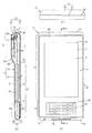
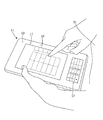
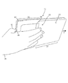
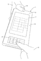
図1(A)は、第1の実施形態に係る決済端末装置11の一例を示す平面図である。図1(B)は、図1(A)のA−A断面図である。図1(C)は、図1(A)に示した厚肉側ケース端面13の上面図である。図2は、決済端末装置11の一例を示す斜視図である。図3(A)は、決済端末装置11の一例を示す背面図である。図3(B)は、図3(A)の側面図である。
(First embodiment)
FIG. 1A is a plan view showing an example of a
決済端末装置11は、例えば、ケース15、第1の入力/表示部17、及びPIN入力キー57、を有する。ケース15は、筐体の一例である。PIN入力キー57は、PINを入力するためのキーである。
The
ケース15は、例えば、表面19(第1の面の一例)が平面で形成される。表面19は、例えば矩形状を有する。ケース15は、決済端末装置11の厚み方向に二分割される表面ケース21と背面ケース23とによって組み合わされる。表面ケース21と背面ケース23とは、互いに結合され、例えば複数のねじ(図示略)によって固定される。
In the
表面ケース21は、表面19の四方の周縁が、表面19の上方から見て、背面25(第2の面の一例)に向かって、下り勾配の表面側外周傾斜面27で形成される。背面ケース23は、背面25の四方の周縁が、背面25の下方から見て、上り勾配の背面側外周傾斜面29で形成される。ケース15は、表面ケース21と背面ケース23が組み合わされると、表面側外周傾斜面27と背面側外周傾斜面29との接続部が稜線となり、輪郭となる。
The
ケース15は、長手方向一端側(図3の上側)が上側、長手方向他端側(図3の下側)が下側となる。ケース15は、長手方向に直交する方向が幅方向となる。ケース15(即ち、決済端末装置11)は、下側が手前となる向きでサービス提供者31に持たれる(図6参照)。ケース15は、表面19と背面25とがほぼ平行となる。
The
背面25の長手方向一端側は、段部33を有し、ケース15の厚み方向に突出した厚部35となって形成される。従って、厚部35以外の背面25は、厚部35よりも薄い薄部37となる。厚部35における筐体の厚み方向の長さは、薄部37における筐体の厚み方向の長さよりも長い。本第1の実施形態の段部33は、厚部35の背面25から薄部37の背面25に向かって下り勾配の段部傾斜面39で形成されているが、例えば垂直面で形成されてもよい。段部33は、ケース15の幅方向に亘って形成され、つまり一端側の端辺と略平行に形成される。
One end side in the longitudinal direction of the
厚部35は、例えば、ケース15の長手方向一端側(厚肉側ケース端面13)から親指41(図7参照)と人差し指43の間にある指股45で挟み込んで、包むような形で保持(把持)される(図7参照)。この場合、ケース15では、親指41が厚部35の表面19を押さえ、親指41を除く4本の指の先端側(爪側)が段部33に添えられる。背面25は、掌に載せた状態で把持される。つまり、厚部35は、表面19を押さえる親指41と、段部33に接して背面25を押さえる親指以外の少なくとも一本の指で、挟んで保持可能となる。従って、厚部35のケース15の長手方向に沿う方向の寸法Lは、親指41と人差し指43の間にある指股45から、親指41を除く4本の指の何れかの先端側(爪側)までの距離よりも短く設定される。これにより、ユーザは、段部33に指先を添えた厚部35の厚肉側ケース端面13からの把持できる。もしくは、ケース15の段部傾斜面39が、人差し指の親指との対向側面に添えられて把持されてもよい。
The
表面ケース21には、第1の入力/表示部17が配置される第1開口部47と、PIN入力キー57が配置される第2開口部49と、が形成される。第1開口部47と第2開口部49とが形成された表面ケース21の表面19は、透明な表面パネル51によって覆われる。第1の入力/表示部17は、例えば感圧式の透明シート状の第1のタッチ入力検出部(タッチパネル)53(図4参照)が第1の表示部(例えば液晶パネルや有機ELディスプレイなど)55に積層されて構成される。
The
PIN入力キー57は、ケース15の長手方向他端側の表面19に配置される。PIN入力キー57は、セキュア領域の少なくとも一部において印刷されている。PIN入力キー57は、第2のタッチ入力検出部59(図4参照)に重ねて配置される。従って、PIN入力キー57が操作(例えば押下、接触)されることは、第2のタッチ入力検出部59により検出される。従って、第2のタッチ入力検出部59は、認証情報の入力を検出する入力検出部の一例である。PIN入力キー57は、第1の入力/表示部17と同様に、タッチパネルが表示部に積層されて構成されてもよいし、物理的なキーボタンであってもよい。さらに、PIN入力キー57は、第2の表示部(図示しない)を第2のタッチ入力検出部59に重ねてケース15の内側に配置して、第2のタッチ入力検出部59とともにタッチパネルディスプレイを構成し、PIN入力キー57のキー枠線やキートップ文字を第2の表示部に表示してもよい。
The
第1の入力/表示部17は、厚部35の少なくとも一部分に重なって表面19に配置される。
The first input /
決済端末装置11では、ケース15の長手方向一端側の厚肉側ケース端面13と、第1の入力/表示部17との間の表面19に、親指41を配置する指置面63が形成されてもよい。なお、指置面63は、特別に専用部位を形成するのではなく、第1の入力/表示部17が配置されていない第1開口部47の周縁の一部または枠部とすることができる。
In the
ケース15は、表面ケース21と背面ケース23とによって組み合わされた内部が、部品収容空間となる。決済端末装置11は、耐タンパ性を有するセキュア領域65と、耐タンパ性を有しない非セキュア領域67と、を有する。
The interior of the
「耐タンパ性」とは、情報処理装置内部のソフトウェアやハードウェアの不正な解析、改変や、情報処理装置内部の情報の不正な奪取、改変、利用不能にする攻撃に対する耐性のことであり、耐タンパ性は、例えば、ソフトウェア又はハードウェアが備える内部構造や記憶しているデータの解析の困難さである。耐タンパ性を備えることで、例えば、サービス享受者(例えば顧客)の情報を保護し、取引を安全にできる。 “Tamper resistance” refers to resistance to attacks that illegally analyze or modify software or hardware inside the information processing device, or illegally take, modify, or use information inside the information processing device. Tamper resistance is, for example, the difficulty of analyzing internal structures provided in software or hardware and stored data. By providing tamper resistance, for example, information of service users (for example, customers) can be protected and transactions can be made safe.
セキュア領域65は、ケース15の長手方向他端側に配置される。非セキュア領域67は、セキュア領域65以外の領域となる。セキュア領域65は、例えば、秘匿すべき情報を有するセキュア部材を収容する。セキュア部材は、例えば複数の部材を含む。セキュア部材は、ケース15の長手方向他端側にPIN入力キー57と重なって配置される。セキュア領域65は、例えば、物理的な侵入を検知するタンパ検知部69(図4参照)を備える。
The
セキュア部材は、例えば、第2のタッチ入力検出部59、接触型ICカードリーダ部71、これらを制御する制御部としての機能を有する第2のCPU73、タンパ検知部69、及びプリント回路基板(図示略)を含む。
The secure member includes, for example, a second touch
セキュア領域65では、例えば、プログラム自体は暗号化されており、制御部が、検証されたプログラムについて実行時に必要な分を復号して実行するソフトウェアを格納してもよい。セキュア領域65は、例えば、セキュア領域65の閉塞が解除されると、秘密情報を消去若しくは所定の値で上書きして安全に書き潰す回路、又は動作を停止する回路を含んでもよい。
In the
タンパ検知部69は、例えば、セキュア領域65に対する物理的な侵入(分解、破壊等)を検知する。タンパ検知部69は、例えば、セキュア領域65に対して物理的に侵入し、内部の情報を読み取りまたは改変しようとする試みがあった場合、この試みを検出し、対抗する上記した動作(例えば秘密情報を消去または上書きする)を実行させる。
The
非セキュア領域67は、例えば、秘匿すべき情報を有しない非セキュア部材を収容する。非セキュア部材は、例えば、複数の部材を含み、主に厚部35に収容される。非セキュア部材は、例えば、磁気カードリーダ部75、バーコード読み取り用のアウトカメラ77(撮像部の一例)を含む。アウトカメラ77は、厚部35の背面25に露出する対物レンズ79を有する。この他、非セキュア領域67には、例えば、バッテリ81、メイン基板85、第1の入力/表示部17、が含まれる。
The
厚部35は、非セキュア領域67に形成される。厚部35には、例えば、アウトカメラ77、磁気カードリーダ部75、メイン基板85の一部、第1の入力/表示部17の一部が積層配置される。
The
ケース15の長手方向一端側の厚肉側ケース端面13には、磁気カードリーダ部75のカードスロット87が配置される。磁気カードリーダ部75は、カードスロット87の溝を挟み、一対の磁気ヘッド89を備える。磁気ヘッド89は、カードスロット87の片側に配置されてもよい。
A
ケース15の長手方向他端側のセキュア側ケース端面91には、接触型ICカードリーダ部71のカード挿入部93が配置される。
A
次に、決済端末装置11のハードウェア構成例について説明する。
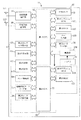
図4は、決済端末装置11のハードウェア構成例を示すブロック図である。
Next, a hardware configuration example of the
FIG. 4 is a block diagram illustrating a hardware configuration example of the
決済端末装置11は、非セキュア領域67及びセキュア領域65を備える。非セキュア領域67は、図4に図示するその矩形の枠内から、後述のセキュア領域65を除いた領域を指す。非セキュア領域67には、第1のCPU95(Central Processing Unit)、局所無線通信部97、広域無線通信部99、第1の入力/表示部17、及び第1のタッチ入力検出部53が設けられる。
The
また、非セキュア領域67には、第1のフラッシュROM101(Read Only Memory)、第1のRAM103(Random Access Memory)、キー入力部105、磁気カードリーダ部75、第1のIF部107(Interface)、電源部109、及びバッテリ81が設けられる。
The
非セキュア領域67では、第1のCPU95に対して、各種の構成部が接続される。第1のCPU95は、非セキュア領域67における構成部の全体を統括する。第1のCPU95は、例えば、第1のフラッシュROM101に格納されたプログラムを実行することで、各種制御、処理、設定、判定等を行う。非セキュア領域67の第1のCPU95における実行環境は、セキュア領域の第2のCPU73における実行環境と比べ、制限が少なくされており、多様なアプリケーションプログラムが実行でき、決済端末装置11の高機能化や広範囲な用途への応用を容易にしている。
In the
局所無線通信部97は、局所無線通信アンテナ111と接続され、図示しない局所無線通信路を用いて、例えば無線LAN通信する機能を有する。局所無線通信部97は、無線LAN通信以外の通信(例えばBluetooth(登録商標)通信)を行ってもよい。
The local
広域無線通信部99は、広域無線通信アンテナ113と接続され、図示しない広域無線通信路(例えばWAN(Wide Area Network))を介して通信する機能を有する。広域無線通信路における通信は、例えば、無線電話回線(W−CDMA(Wideband Code Division Multiple Access)、CDMA(Code Division Multiple Access)、LTE(Long Term Evolution)などの携帯電話回線)を用いて行われてもよい。
The wide area
第1の表示部55は、第1の入力/表示部17の表示を制御する機能を有する。第1のタッチ入力検出部53は、第1の入力/表示部17に対するタッチ入力を検出する機能を有する。
The
第1のフラッシュROM101は、各種のデータを記憶する機能を有する。記憶されるデータは、業務アプリケーションプログラムやそれら業務に関わるデータでもよいし、決済端末装置11(例えば非セキュア領域67)を制御するためのプログラムでもよい。
The
第1のRAM103は、例えば、決済端末装置11(例えば非セキュア領域67における構成部)の動作に伴う演算処理の際に、演算処理の途中において発生する処理データを、一時的に記憶するために用いられるメモリである。
For example, the
キー入力部105は、非セキュア領域67に配置された入力キー(例えば、バーコードの読み取りを開始するためのスキャン・ボタンなど)からの入力を受け付ける機能を有する。磁気カードリーダ部75は、図1(B)におけるカードスロット87の内部に配置され、磁気カードの磁気ストライプを読み取る機能を有する。
The
電源部109は、バッテリ81からの電源の供給を受けて、非セキュア領域67(例えば、第1のCPU95)へ電源を供給する。第1のCPU95は、電源部109を制御することにより、非セキュア領域67に配された一部または全体の回路に対して、電源供給及び電源供給の停止が可能である。
The
非セキュア領域67及びセキュア領域65は、第1のIF部107及びセキュア領域65に設けられた第2のIF部117を介して、互いに接続され、各種のデータやコマンドの受け渡しが行われる。第1のIF部107と第2のIF部117とは、互いに結合可能である。
The
セキュア領域65には、第2のIF部117、第2のCPU73、タンパ検知部69、接触型ICカードリーダ部71、第2のタッチ入力検出部59、第2のフラッシュROM119、第2のRAM121を設けられる。
The
セキュア領域65では、第2のCPU73に対して、各種の構成部が接続される。第2のCPU73は、セキュア領域65における構成部の全体を統括する。第2のCPU73は、例えば、第2のフラッシュROM119に格納されたプログラムを実行することで、各種制御、処理(例えば、ICカードの読み取り、PINの入力受付/照合)を行う。
In the
タンパ検知部69は、セキュア領域65を監視し、セキュア領域65における例えば分解、破壊、または開封を検知する。つまり、タンパ検知部69は、セキュア領域65における異常の有無を検知する。タンパ検知部69により上記事象が検知された場合、例えば、決済処理を停止させてもよいし、第1の入力/表示部17等によりセキュア領域65において異常がある旨を報知してもよい。
The
接触型ICカードリーダ部71は、カード挿入部93を有する。接触型ICカードリーダ部71に内蔵される電極(図示せず)は、カード挿入部93に接触式ICカードが挿入されると、接触式ICカードの表面に設けられた電極と電気的に接続される。
The contact type IC
第2のタッチ入力検出部59は、PIN入力キー57に対するタッチ入力を検出する機能を有する。例えば、第2のタッチ入力検出部59は、PINを入力するための物理的なキーまたはソフトキーを含むピンパッド(PINPAD)への入力を検出してもよい。第2のタッチ入力検出部59は、例えば、指またはスタイラスペンを用いて、署名の入力を検出してもよい。第2のタッチ入力検出部59は、例えば、指またはスタイラスペンを用いて、PINの手書き入力を検出してもよい。
The second touch
第2のフラッシュROM119は、各種のデータを記憶する機能を有する。記憶されるデータは、決済端末装置11(例えばセキュア領域65における構成部)を制御するためのプログラム、決済において第2のタッチ入力検出部59より入力されたPINの照合を行うためのプログラムなどである。
The
第2のRAM121は、例えば、決済端末装置11(例えばセキュア領域65)の動作に伴う演算処理等の際に、演算処理の途中において発生する処理データを、一時的に記憶するために用いられるメモリである。
The
このように、決済端末装置11は、非セキュア領域67とセキュア領域65とを含む。決済に用いられるカードの認証情報の入力は、セキュア領域65におけるPIN入力キー57に対して行われる。従って、決済端末装置11は、安全性を確保した状態で、決済に用いられるカードの認証情報の入力が可能であり、「耐タンパ性」も確保できる。「耐タンパ性」を必要とする「セキュア」な部分は、セキュア領域65に局所化され、小型化されている(例えば図1(B)参照)。
As described above, the
一方、非セキュア領域67には、例えば、民生用に多数流通している情報端末(例えばスマートフォン、タブレット端末)やその一部が、プラットフォームとして採用されてもよい。
On the other hand, in the
非セキュア領域67において汎用のプラットフォームを採用することで、決済用のアプリケーション・ソフトウェア(決済アプリケーション)、及びその他の業務に用いられるアプリケーション・ソフトウェア(業務アプリケーション)の開発資産の再利用や流用は、容易となる。また、決済アプリケーション及びその他の業務アプリケーションは、例えば高い演算処理能力を備える非セキュア領域67における第1のCPU95により処理されることで、ストレスなく柔軟に動作する。また、決済のスキームが多様化された決済処理や多様な業務アプリケーションが容易に利用できる。
By adopting a general-purpose platform in the
次に、決済端末装置11の作用の一例について説明する。
Next, an example of the operation of the
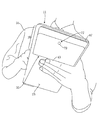
図5は、サービス提供者31の操作状況を決済端末装置11の背面側から見た動作説明図である。図6は、サービス提供者31の操作状況を決済端末装置11の表面側から見た動作説明図である。図7は、サービス提供者31が決済端末装置11をサービス享受者32(図8参照)に差し出す際の状況を背面側から見た動作説明図である。図8は、サービス提供者31が厚部35を持ち、サービス享受者32がPIN入力キー57を操作する状況を表す動作説明図である。
FIG. 5 is an operation explanatory diagram of the operation status of the
決済端末装置11は、携帯性を備える。サービス提供者31は、例えば、決済処理において、認証情報(例えばPIN、署名)を入力する段階となるまで、図5,図6に示すように、PIN入力キー57が手前側となる向きでケース15を持つ。また、サービス提供者31は、例えば、第1の入力/表示部17及び第1のタッチ入力検出部53を用いて、商品情報、決済方法、支払金額、支払回数等を入力する。この段階では、例えば、磁気カードを磁気カードリーダ部75に通し、又は、接触式カードを接触型ICカードリーダ部71に挿入する。カードの読み取りおよび商品情報、決済方法、支払金額、支払回数等の入力が終了すると、認証情報を入力するタイミングとなる。
The
認証情報を入力する段階では、サービス提供者31は、図7に示すように、例えば、厚部35を持ってケース15を所定角度(例えば180°)回転してサービス享受者32側に向ける。すると、決済端末装置11は、図8に示すように、PIN入力キー57が、サービス享受者32側から見て手前側になる。つまり、入力/表示部17を挟んで、厚部35がサービス享受者32から遠い側に配置され、セキュア領域65がサービス享受者32に近い側に配置される。厚部35に実装される非セキュア領域67と薄部37に実装されるセキュア領域65とが、ケース15において互いに反対側に配置される。ここで、サービス享受者32側から見て手前側とは、第1の入力/表示部17かつまたはPIN入力キー57に表示される文字が正立する向きにて、ケース15におけるそれら文字の下方側である。
At the stage of inputting authentication information, as shown in FIG. 7, for example, the
従って、サービス享受者32はPIN番号を入力する決済操作がし易くなり、サービス提供者31は、厚部35によって決済端末装置11が持ち易くなる(図7参照)。また、決済端末装置11は、盗難時のサービス享受者32側からの引っ張り力Fに対しても、厚部35の段部33が設けられていることで、確実にホールド(把持)できる。
Accordingly, the
厚部35には、通常の撮影の他にバーコードの読み取りを行うためのアウトカメラ77、磁気カードリーダ部75などの、他の部材と比べて厚みの大きい部材が収容される。そのため、厚部35の厚みは他の部分よりも大きく、ホールド性の向上に寄与する。
The
セキュア領域65のセキュア部材(第2のCPU73、接触型ICカードリーダ部、第2のタッチ入力検出部59、タンパ検知部69など)は、入力/表示部17を挟んで厚部35とは反対側に、必要最小スペースで集中配置される。このため、セキュア領域65の耐タンパ性の確保が容易となり、セキュリティを確保できる。加えて、セキュア領域65のセキュア部材には、セキュア領域65を薄型化する上での障害となる部材が含まれていないので、セキュア領域65は薄型化も可能である。従って、厚みの大きい非セキュア部材と薄型化が可能なセキュア部材とを適材適所に配置することによって形成された形状が、機能性(例えば、ホールド性、決済のし易さ、耐タンパ性確保の容易性)を発現できる。
The secure member (
決済端末装置11では、厚部35の背面25に、アウトカメラ77の対物レンズ79が配置される。アウトカメラ77では、例えば、対物レンズ79に対し、撮像素子及び基板が、対物レンズ79の光軸に沿う方向に並んで設けられる。
In the
アウトカメラ77は、例えば商品に付されたバーコードを撮像し、第1のCPU95により、撮像画像から商品情報等が取得される。なお、アウトカメラ77に代えて、サービス提供者31またはサービス享受者32を撮影するインカメラであってもよい。この場合、インカメラの対物レンズは、表面19側に設け、背面25の対物レンズ79は設けない。
The out
決済端末装置11では、接触型ICカードリーダ部71がセキュア領域65に配置される。磁気カードリーダ部75のカードスロット87は、厚部35に配置される。従って、磁気カードリーダ部75のカードスロット87は、厚部35の厚肉化に寄与し、セキュア領域65の薄肉化にも寄与できる。
In the
決済端末装置11では、厚部35を持って、PIN入力キー57をサービス享受者32側に向けた場合、厚部35を持つ親指41が指置面63に配置される。親指41が指置面63に収まる場合、親指41は、第1の入力/表示部17、及び第1の入力/表示部17に積層される第1のタッチ入力検出部53にかからない。つまり、親指41が第1の入力/表示部17をタッチしない。これにより、不用意に第1の入力/表示部17に触れて誤操作することを抑制できる。なお、第1の入力/表示部17の面は、操作表示面の一例である。
In the
このように、決済端末装置11によれば、セキュリティを確保でき、サービス提供者31が持ち易くでき、サービス享受者32が決済操作し易くできる。
Thus, according to the
(第2の実施形態)
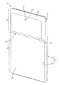
図9は、第2の実施形態に係る決済端末装置125の一例を示す斜視図である。図10(A)は、決済端末装置125の一例を示す背面図である。図10(B)は、図10(A)の側面図である。なお、図9及び図10(A),(B)では、図1〜図8に示した部材と同一の部材には同一の符号を付し、重複する説明を省略又は簡略化する。
(Second Embodiment)
FIG. 9 is a perspective view showing an example of a
決済端末装置125は、一対の壁部127を備える。壁部127は、段部33の延在方向の両端に接続して薄部37の背面25に形成され、厚部35から離れるに従って徐々に低くなり、薄部37の背面25と同一平面となる。壁部127が低くなるとは、筐体の厚み方向に沿う長さが短くなることに相当する。
The
サービス提供者31は、例えば、一対の壁部127のうち一方の壁部127を、親指41と人差し指43とで、又は指股45で、厚肉側ケース端面13から挟み込むことにより、決済端末装置125を把持してもよい。
The
サービス提供者31は、例えば、親指41を除く4本の指の少なくとも先端側(爪側)を、背面25における段部33と壁部127とにより囲まれたコ字状領域に添え、背面25を掌に載せた状態で、決済端末装置125を装置側壁部129から把持してもよい。この場合、厚肉側ケース端面13を把持する縦持ち(図7参照)に対し、装置側壁部129を把持する横持ち(図示略)となる。
For example, the
縦持ちによれば、例えば、決済端末装置125がサービス提供者31の掌から滑落しそうになっても、一方又は両方の壁部127あるいは段部33が、サービス提供者31の人差し指43又は小指の側面と接触して、決済端末装置125の滑落を抑止できる。
According to the vertical holding, for example, even if the
横持ちでは、サービス提供者31は、指股45で、壁部127の一方を装置側壁部129から挟み込む。この場合、サービス提供者31は、決済端末装置125の側面と表面19との角部付近に、親指41の第一関節と第二関節との間にある部分を置く。また、サービス提供者31は、背面25において、段部33と壁部127とにより囲まれた領域に、親指41を除く4本の指を置く。これにより、決済端末装置125を把持する。この把持状態では、一方の壁部127がサービス提供者31の親指41と人差し指43とに、又は指股45に挟みこまれるので、決済端末装置125の把持状態が安定し、滑落の発生を低減できる。
In the horizontal holding state, the
また、決済端末装置125では、サービス提供者31が、厚部35を持ってケース15を回転させてサービス享受者32側に向ける場合、壁部127が有効に作用する。サービス提供者31は、認証情報の入力前の段階では、図5に示すように、例えば左手で薄部37を持つとする。この場合、例えば、表面19は親指41、背面25はその他の指で押さえられる。この場合、例えば人差し指43は、段部33に添えられる。
Moreover, in the
ケース15を回転してサービス享受者32側に向ける場合、サービス提供者31は、例えば、ケース15を持つ図5に示す左手から、持ち手を変えて、図7に示す右手で厚部35を持つ。例えば、サービス提供者31は、右手の親指41で厚部35の表面19を押さえ、親指以外の少なくとも一本の指を段部33に添えてケース15を持つ。この場合、段部33の延在方向の両端に、壁部127が存在することで、段部33に添えられる指が、横滑りして段部33から外れることを抑制できる。つまり、ホールドが解除され難くできる。従って、ケース15を回転してサービス享受者32側に向ける場合の決済端末装置125の落下を抑制できる。
When the
このように、決済端末装置125によれば、セキュリティを確保でき、サービス提供者31が持ち易くでき、サービス享受者32が決済操作し易くできる。
Thus, according to the
なお、本発明は、上記実施形態の構成に限られるものではなく、特許請求の範囲で示した機能、または本実施形態の構成が持つ機能が達成できる構成であればどのようなものであっても適用可能である。 The present invention is not limited to the configuration of the above-described embodiment, and any configuration can be used as long as the functions shown in the claims or the functions of the configuration of the present embodiment can be achieved. Is also applicable.
例えば、上記実施形態では、認証情報としてPINが入力されることを例示したが、他の認証情報(例えば署名、PIN手書き情報、指紋情報、その他の認証情報)が入力されてもよい。 For example, in the above embodiment, PIN is input as authentication information, but other authentication information (for example, signature, PIN handwritten information, fingerprint information, and other authentication information) may be input.
(本発明の一態様の概要)
本発明の一態様の決済端末装置は、操作表示面を有する第1の面と、前記操作表示面とは反対側の第2の面と、前記第2の面の一端側に、前記一端側の端辺と略平行に形成された段部と、を有する筐体を備え、前記段部に隣接する前記一端側における前記筐体の厚み方向の長さは、前記段部に隣接する他端側における前記筐体の厚み方向の長さよりも長く、前記筐体の前記一端側に、耐タンパ性を有しない非セキュア領域が形成され、前記筐体の前記他端側に、耐タンパ性を有するセキュア領域が形成される。
(Overview of one embodiment of the present invention)
The settlement terminal device according to one aspect of the present invention includes a first surface having an operation display surface, a second surface opposite to the operation display surface, and one end side of the second surface. And the length of the casing in the thickness direction on the one end side adjacent to the stepped portion is the other end adjacent to the stepped portion. A non-secure region having no tamper resistance is formed on the one end side of the casing and longer than the length in the thickness direction of the casing on the side, and tamper resistance is provided on the other end side of the casing. A secure area is formed.
この構成によれば、セキュア部材が収納される領域(セキュア領域)と、非セキュア部材が収容される領域(非セキュア領域)と、が分離されており、セキュア部材を集中配置できるので、セキュリティを確保できる。また、段部を境に、一端側が厚部となり、他端側が薄部となる。サービス提供者は、例えば、認証情報の入力前までは、段部と薄部とを支持して決済端末装置を把持し、認証情報の入力時には、厚部を支持して決済端末装置を把持できる。従って、サービス提供者は決済端末装置を容易に把持できる。また、認証情報の入力時に、サービス提供者が厚部を支持した場合、サービス享受者側にはセキュア領域が位置するので、決済操作(例えば認証情報の入力操作)を容易に実施できる。 According to this configuration, the area in which the secure member is accommodated (secure area) and the area in which the non-secure member is accommodated (non-secure area) are separated, and the secure members can be centrally arranged. It can be secured. Further, with the stepped portion as a boundary, one end side becomes a thick portion and the other end side becomes a thin portion. For example, before the authentication information is input, the service provider can hold the payment terminal device by supporting the stepped portion and the thin portion, and can support the thick portion and grip the payment terminal device when inputting the authentication information. . Therefore, the service provider can easily grasp the payment terminal device. Further, when the service provider supports the thick part at the time of inputting the authentication information, the secure operation is located on the service receiver side, so that the settlement operation (for example, the authentication information input operation) can be easily performed.
また、本発明の一態様の決済端末装置は、前記非セキュア領域に、撮像部が配置される。 In the settlement terminal device according to an aspect of the present invention, an imaging unit is disposed in the non-secure area.
この構成によれば、撮像部には所定の厚みが必要であるので、非セキュア領域にはセキュア領域と比較すると大きな収容スペースが確保される。従って、筐体の一端側の厚み方向の厚さを長くでき、決済端末装置のホールド性を向上できる。また、セキュア領域の薄型化も実現できる。 According to this configuration, since the imaging unit needs to have a predetermined thickness, a large accommodation space is ensured in the non-secure area compared to the secure area. Therefore, the thickness in the thickness direction on the one end side of the housing can be increased, and the holdability of the settlement terminal device can be improved. In addition, the secure area can be reduced in thickness.
また、本発明の一態様の決済端末装置は、前記非セキュア領域に、磁気カードのカードスロットが配置される。 In the settlement terminal device according to an aspect of the present invention, a card slot of a magnetic card is disposed in the non-secure area.
この構成によれば、磁気カードリーダ部の磁気ヘッドには所定の厚みが必要であるので、非セキュア領域にはセキュア領域と比較すると大きな収容スペースが確保される。従って、筐体の一端側の厚み方向の厚さを長くでき、決済端末装置のホールド性を向上できる。また、セキュア領域の薄型化も実現できる。すなわち、厚みの大きい非セキュア部材と薄型化が可能なセキュア部材とを適材適所に配置することによって形成された形状が、機能性(例えば、ホールド性、決済のし易さ、耐タンパ性確保の容易性)を発現できる。 According to this configuration, since the magnetic head of the magnetic card reader unit needs to have a predetermined thickness, a large accommodation space is secured in the non-secure area compared to the secure area. Therefore, the thickness in the thickness direction on the one end side of the housing can be increased, and the holdability of the settlement terminal device can be improved. In addition, the secure area can be reduced in thickness. In other words, the shape formed by arranging a thick non-secure member and a secure member that can be thinned in the right place makes it possible to maintain functionality (for example, holdability, ease of settlement, and tamper resistance). Ease).
また、本発明の一態様の決済端末装置は、前記セキュア領域に、認証情報の入力を検出する入力検出部が配置される。 In the settlement terminal device according to an aspect of the present invention, an input detection unit that detects an input of authentication information is disposed in the secure area.
この構成によれば、入力検出部のセキュリティが確保される。また、セキュア領域は、サービス享受者による認証情報の入力時には、サービス享受者の手前側に位置するので、入力操作をしている入力検知部がサービス享受者以外の目に触れづらい安全な入力を可能にし、かつ認証情報の入力操作の操作性を向上できる。 According to this configuration, the security of the input detection unit is ensured. In addition, the secure area is positioned in front of the service beneficiary when the authentication information is input by the service beneficiary, so that the input detection unit performing the input operation makes it difficult for the non-service beneficiary to touch. And the operability of the authentication information input operation can be improved.
また、本発明の一態様の決済端末装置は、前記操作表示面が、前記第1の面において、前記一端側の端辺から所定距離以上離間されて配置される。 In the settlement terminal device according to an aspect of the present invention, the operation display surface is arranged on the first surface so as to be separated from the end on the one end side by a predetermined distance or more.
この構成によれば、サービス提供者が、サービス享受者による認証情報の入力時に決済端末装置を把持する場合、筐体の一端側を把持するが、この場合に親指が操作表示面に触れることを抑制できる。従って、操作表示面のタッチによる誤操作を抑制できる。 According to this configuration, when the service provider grips the settlement terminal device when the authentication information is input by the service receiver, the service provider grips one end side of the housing. In this case, the thumb touches the operation display surface. Can be suppressed. Therefore, it is possible to suppress erroneous operations due to touch on the operation display surface.
本発明の一態様の決済端末装置は、前記筐体が、前記第2の面において、前記段部の延在方向の両端に接続され、前記一端側の端辺から離れる程、前記筐体の厚み方向に沿う長さが短くなる壁部を備える。 In the settlement terminal device according to one aspect of the present invention, the casing is connected to both ends of the stepped portion in the extending direction on the second surface, and the farther away from the end on the one end side, A wall portion having a shorter length along the thickness direction is provided.
この構成によれば、段部の代わりに、又は段部とともに壁部を支持することで、決済端末装置を把持できる。従って、決済端末装置を容易に把持でき、決済端末装置を落下させる可能性を低減できる。例えば、段部に添えられる指が横滑りして段部から外れ、ホールドが解除されることを抑制できる。 According to this configuration, the settlement terminal device can be gripped by supporting the wall portion instead of the step portion or together with the step portion. Therefore, the payment terminal device can be easily grasped, and the possibility of dropping the payment terminal device can be reduced. For example, it is possible to prevent the finger attached to the stepped part from sliding sideways and coming off the stepped part and releasing the hold.
本発明は、セキュリティを確保でき、サービス提供者が持ち易く、サービス享受者が決済操作し易い決済端末装置等に有用である。 INDUSTRIAL APPLICABILITY The present invention is useful for a payment terminal device or the like that can ensure security, is easy for a service provider, and is easy for a service receiver to perform a payment operation.
11 決済端末装置
13 厚肉側ケース端面
15 ケース
17 第1の入力/表示部
19 表面
21 表面ケース
23 背面ケース
25 背面
27 表面側外周傾斜面
29 背面側外周傾斜面
31 サービス提供者
32 サービス享受者
33 段部
35 厚部
37 薄部
39 段部傾斜面
41 親指
43 人差し指
45 指股
53 第1のタッチ入力検出部
55 第1の表示部
57 PIN入力キー
59 第2のタッチ入力検出部
63 指置面
65 セキュア領域
67 非セキュア領域
69 タンパ検知部
71 接触型ICカードリーダ部
73 第2のCPU
75 磁気カードリーダ部
77 アウトカメラ
79 対物レンズ
81 バッテリ
85 メイン基板
87 カードスロット
89 磁気ヘッド
91 セキュア側ケース端面
93 カード挿入部
95 第1のCPU
97 局所無線通信部
99 広域無線通信部
101 第1のフラッシュROM
103 第1のRAM
105 キー入力部
107 第1のIF
109 電源部
111 局所無線通信アンテナ
113 広域無線通信アンテナ
117 第2のIF
119 第2のフラッシュROM
121 第2のRAM
125 決済端末装置
127 壁部
129 装置側壁部
DESCRIPTION OF
75 Magnetic
97 Local
103 first RAM
105
109 Power supply unit 111 Local
119 Second flash ROM
121 Second RAM
125
Claims (6)
前記第1の操作表示面及び第2の操作表示面とは反対側の第2の面と、
前記第2の面の一端側に、前記一端側の端辺と略平行に形成された段部と、
を有する筐体を備え、
前記段部に隣接する前記一端側における前記筐体の厚み方向の長さは、前記段部に隣接する他端側における前記筐体の厚み方向の長さよりも長く、
前記筐体の前記一端側に、決済アプリケーション及びその他の業務アプリケーションを実行する非セキュア領域が形成され、
前記筐体の前記他端側に、決済処理に関するサービス享受者の認証情報の照合を実行するセキュア領域が形成され、
前記第1の操作表示面には、前記決済処理に関する商品情報、決済方法、支払金額、支払回数等の情報が入力かつ表示され、
前記第2の操作表示面には、前記認証情報が入力され、
前記セキュア領域は、前記第2の操作表示面の前記認証情報が入力される領域を有する、
可搬型決済端末装置。 A first surface having a first operation display surface and a second operation display surface ;
A second surface opposite to the first operation display surface and the second operation display surface ;
On one end side of the second surface, a step portion formed substantially parallel to the end side of the one end side;
A housing having
The length in the thickness direction of the casing on the one end side adjacent to the stepped portion is longer than the length in the thickness direction of the casing on the other end side adjacent to the stepped portion,
A non-secure area for executing a payment application and other business applications is formed on the one end side of the housing,
On the other end side of the housing, a secure area for executing verification of the authentication information of the service receiver regarding the payment processing is formed,
On the first operation display surface, product information related to the settlement process, settlement method, payment amount, number of payments and other information are input and displayed,
The authentication information is input to the second operation display surface,
The secure region has a region where the authentication information of the second operation display surface is inputted,
Portable payment terminal device.
前記非セキュア領域に、撮像部が配置された、可搬型決済端末装置。 The portable payment terminal device according to claim 1,
A portable payment terminal apparatus in which an imaging unit is arranged in the non-secure area.
前記非セキュア領域に、磁気カードのカードスロットが配置された、可搬型決済端末装置。 The portable payment terminal device according to claim 1 or 2,
A portable settlement terminal device in which a card slot of a magnetic card is arranged in the non-secure area.
前記セキュア領域に、認証情報の入力を検出する入力検出部が配置された、可搬型決済端末装置。 The portable payment terminal device according to any one of claims 1 to 3,
A portable settlement terminal device in which an input detection unit for detecting an input of authentication information is arranged in the secure area.
前記操作表示面は、前記第1の面において、前記一端側の端辺から所定距離以上離間されて配置された、可搬型決済端末装置。 It is a portable payment terminal device of any one of Claims 1-4,
The portable payment terminal device, wherein the operation display surface is arranged on the first surface so as to be spaced a predetermined distance or more from the end on the one end side.
前記操作表示面とは反対側の第2の面と、
前記第2の面の一端側に、前記一端側の端辺と略平行に形成された段部と、を有する筐体を備え、
前記段部に隣接する前記一端側における前記筐体の厚み方向の長さは、前記段部に隣接する他端側における前記筐体の厚み方向の長さよりも長く、
前記筐体の前記一端側に、耐タンパ性を有しない非セキュア領域が形成され、
前記筐体の前記他端側に、耐タンパ性を有するセキュア領域が形成され、前記筐体は、前記第2の面において、前記段部の延在方向の両端に接続され、前記一端側の端辺から離れる程、前記筐体の厚み方向に沿う長さが短くなる壁部を備える、可搬型決済端末装置。 A first surface having an operation display surface;
A second surface opposite to the operation display surface;
A housing having a step formed on one end side of the second surface substantially parallel to the end side of the one end side;
The length in the thickness direction of the casing on the one end side adjacent to the stepped portion is longer than the length in the thickness direction of the casing on the other end side adjacent to the stepped portion,
A non-secure region not having tamper resistance is formed on the one end side of the housing,
A tamper-resistant secure region is formed on the other end side of the casing, and the casing is connected to both ends in the extending direction of the step portion on the second surface, A portable settlement terminal device comprising a wall portion whose length along the thickness direction of the housing becomes shorter as it is farther from the end side.
Priority Applications (3)
| Application Number | Priority Date | Filing Date | Title |
|---|---|---|---|
| JP2014066690A JP5861069B2 (en) | 2014-03-27 | 2014-03-27 | Portable payment terminal |
| EP15159094.0A EP2924665A1 (en) | 2014-03-27 | 2015-03-13 | Settlement terminal device |
| US14/666,788 US9679166B2 (en) | 2014-03-27 | 2015-03-24 | Settlement terminal device |
Applications Claiming Priority (1)
| Application Number | Priority Date | Filing Date | Title |
|---|---|---|---|
| JP2014066690A JP5861069B2 (en) | 2014-03-27 | 2014-03-27 | Portable payment terminal |
Publications (2)
| Publication Number | Publication Date |
|---|---|
| JP2015191318A JP2015191318A (en) | 2015-11-02 |
| JP5861069B2 true JP5861069B2 (en) | 2016-02-16 |
Family
ID=52813899
Family Applications (1)
| Application Number | Title | Priority Date | Filing Date |
|---|---|---|---|
| JP2014066690A Expired - Fee Related JP5861069B2 (en) | 2014-03-27 | 2014-03-27 | Portable payment terminal |
Country Status (3)
| Country | Link |
|---|---|
| US (1) | US9679166B2 (en) |
| EP (1) | EP2924665A1 (en) |
| JP (1) | JP5861069B2 (en) |
Families Citing this family (31)
| Publication number | Priority date | Publication date | Assignee | Title |
|---|---|---|---|---|
| USD771033S1 (en) * | 2014-01-10 | 2016-11-08 | Panasonic Intellectual Property Management Co., Ltd. | Handheld terminal |
| USD764458S1 (en) * | 2014-01-10 | 2016-08-23 | Panasonic Intellectual Property Management Co., Ltd. | Handheld terminal |
| JP5810329B1 (en) * | 2014-05-28 | 2015-11-11 | パナソニックIpマネジメント株式会社 | Payment terminal device |
| CN106796686A (en) * | 2014-07-22 | 2017-05-31 | Mt信息技术外贸有限公司 | The biometric security for defining method using face recognition and fingerprint is sold and payment terminal |
| JP2016212654A (en) * | 2015-05-11 | 2016-12-15 | 株式会社リコー | Information processing system and user authentication method |
| JP6268500B2 (en) * | 2015-12-22 | 2018-01-31 | パナソニックIpマネジメント株式会社 | Transaction terminal device and security module |
| USD787507S1 (en) * | 2016-02-16 | 2017-05-23 | Panasonic Intellectual Property Management Co., Ltd. | Mobile terminal |
| USD787508S1 (en) * | 2016-02-16 | 2017-05-23 | Panasonic Intellectual Property Management Co., Ltd. | Mobile terminal |
| USD787506S1 (en) * | 2016-02-16 | 2017-05-23 | Panasonic Intellectual Property Management Co., Ltd. | Mobile terminal |
| USD851697S1 (en) * | 2017-12-04 | 2019-06-18 | Clover Network, Inc. | Tablet |
| USD840960S1 (en) * | 2017-12-07 | 2019-02-19 | Giphy, Inc. | Display |
| TWD192496S (en) * | 2018-01-15 | 2018-08-21 | 廣達電腦股份有限公司 | Terminal |
| TWD192495S (en) * | 2018-01-15 | 2018-08-21 | 廣達電腦股份有限公司 | Terminal |
| US10740499B2 (en) | 2018-03-12 | 2020-08-11 | Nuvoton Technology Corporation | Active shield portion serving as serial keypad |
| USD886898S1 (en) * | 2018-11-23 | 2020-06-09 | Fujian Landi Commercial Equipment Co., Ltd. | Mobile payment terminal |
| TWD198625S (en) * | 2018-12-05 | 2019-07-11 | 廣達電腦股份有限公司 | Point of sale machine |
| USD886190S1 (en) * | 2018-12-20 | 2020-06-02 | Fujian Landi Commercial Equipment Co., Ltd. | Payment terminal |
| USD957514S1 (en) * | 2020-06-17 | 2022-07-12 | Shopify Inc. | Point of sale device |
| USD941911S1 (en) * | 2020-07-01 | 2022-01-25 | Pax Computer Technology (Shenzhen) Co., Ltd. | Mobile payment terminal |
| JP6827206B1 (en) * | 2020-09-07 | 2021-02-10 | パナソニックIpマネジメント株式会社 | Payment terminal |
| US11963315B2 (en) * | 2021-03-19 | 2024-04-16 | Deere & Company | Housing for a portable electronic device |
| EP4177934B1 (en) * | 2021-07-27 | 2025-04-02 | Changxin Memory Technologies, Inc. | Semiconductor structure preparation method, semiconductor structure, and semiconductor memory |
| USD1048174S1 (en) * | 2022-12-28 | 2024-10-22 | Banks And Acquirers International Holding | Payment terminal |
| USD1044932S1 (en) * | 2022-12-28 | 2024-10-01 | Banks And Acquirers International Holding | Payment terminal |
| USD1067968S1 (en) * | 2023-02-17 | 2025-03-25 | Fujian Newland Payment Technology Co., Ltd. | Point-of-sale terminal |
| USD1038225S1 (en) * | 2023-05-16 | 2024-08-06 | Banks And Acquirers International Holding | Payment terminal with screen and keyboard |
| USD1096928S1 (en) * | 2023-09-22 | 2025-10-07 | Fujian Landi Commercial Equipment Co., Ltd. | Scan code payment terminal |
| USD1118746S1 (en) * | 2023-11-03 | 2026-03-17 | Fujian Newland Payment Technology Co., Ltd. | POS machine |
| USD1099206S1 (en) * | 2024-01-02 | 2025-10-21 | Pax Computer Technology (Shenzhen) Co., Ltd. | POS terminal |
| JP7482468B1 (en) | 2024-02-28 | 2024-05-14 | パナソニックIpマネジメント株式会社 | Portable payment terminal |
| USD1121018S1 (en) * | 2024-03-21 | 2026-03-31 | Bluebird Inc. | Card payment terminal |
Family Cites Families (33)
| Publication number | Priority date | Publication date | Assignee | Title |
|---|---|---|---|---|
| JPH0353044A (en) | 1989-07-19 | 1991-03-07 | Sumitomo Metal Ind Ltd | Steel stock excellent in toughness in weld heat-affected zone and its production |
| JPH0749872Y2 (en) * | 1989-09-29 | 1995-11-13 | アイコム株式会社 | Portable radio housing structure |
| US6266685B1 (en) * | 1991-07-11 | 2001-07-24 | Intermec Ip Corp. | Hand-held data collection system with stylus input |
| JPH0749872A (en) | 1992-09-22 | 1995-02-21 | Nec Software Ltd | Automatic key word extraction system |
| US5970146A (en) * | 1996-05-14 | 1999-10-19 | Dresser Industries, Inc. | Data encrypted touchscreen |
| JPH10240420A (en) | 1997-02-27 | 1998-09-11 | Toshiba Corp | Portable information devices using pen input |
| IT245067Y1 (en) * | 1998-06-19 | 2002-03-19 | 4P Srl | MULTI-FUNCTION HANDHELD ELECTRONIC PROCESSOR STRUCTURE. |
| JP2001256409A (en) * | 2000-03-10 | 2001-09-21 | Hitachi Information Technology Co Ltd | Debit payment terminal device and debit payment method |
| FR2812744A1 (en) * | 2000-08-04 | 2002-02-08 | Dassault Automatismes | ELECTRONIC PAYMENT DEVICE USING A CONSUMER APPARATUS AND A COMMERCIAL APPARATUS COMMUNICATING THROUGH A WIRELESS LINK |
| US6968453B2 (en) * | 2001-01-17 | 2005-11-22 | International Business Machines Corporation | Secure integrated device with secure, dynamically-selectable capabilities |
| FR2825495B1 (en) * | 2001-05-31 | 2003-09-26 | Schlumberger Systems & Service | ELECTRONIC PAYMENT TERMINAL, CHIP CARD SUITABLE FOR SUCH A TERMINAL AND METHOD FOR LOADING A SECRET KEY INTO SUCH A TERMINAL |
| JP4763163B2 (en) * | 2001-06-27 | 2011-08-31 | 富士通フロンテック株式会社 | Transaction terminal device |
| JP2003157239A (en) * | 2001-11-22 | 2003-05-30 | Matsushita Electric Ind Co Ltd | PIN input device and mobile phone and payment system |
| US20040024710A1 (en) * | 2002-03-07 | 2004-02-05 | Llavanya Fernando | Secure input pad partition |
| USD499134S1 (en) * | 2002-05-06 | 2004-11-30 | Exadigm, Inc. | Point-of-sale device |
| AU2002328624A1 (en) * | 2002-08-16 | 2004-03-03 | Fujitsu Frontech Limited | Transaction terminal unit, and transaction terminal control method |
| US20040167820A1 (en) * | 2003-02-26 | 2004-08-26 | Diana Melick | Two part payment terminal |
| FR2864286B1 (en) * | 2003-12-19 | 2006-03-10 | Thales Sa | ELECTRONIC MODULE, IN PARTICULAR FOR AN ELECTRONIC PAYMENT TERMINAL |
| JP4636809B2 (en) | 2004-03-31 | 2011-02-23 | 富士通フロンテック株式会社 | Information processing terminal and information security protection method thereof |
| JP4616013B2 (en) * | 2005-01-12 | 2011-01-19 | 富士通フロンテック株式会社 | Payment-enabled application that ensures security |
| US7934660B2 (en) * | 2006-01-05 | 2011-05-03 | Hand Held Products, Inc. | Data collection system having reconfigurable data collection terminal |
| US7497378B2 (en) * | 2006-12-08 | 2009-03-03 | Verifone, Inc. | Anti-tampering protection for magnetic stripe reader |
| JP4893411B2 (en) * | 2007-03-28 | 2012-03-07 | カシオ計算機株式会社 | Terminal device and program |
| JP4557033B2 (en) * | 2008-03-31 | 2010-10-06 | ブラザー工業株式会社 | Unauthorized operation prevention system, portable terminal device with unauthorized operation prevention function, mounting device with unauthorized operation prevention function, unauthorized operation prevention method, and unauthorized operation prevention program |
| JP2011095840A (en) * | 2009-10-27 | 2011-05-12 | Ed-Contrive Co Ltd | Usb memory device having authentication function |
| JP4886063B2 (en) | 2009-12-04 | 2012-02-29 | 株式会社エヌ・ティ・ティ・ドコモ | Status notification device, status notification method, and program |
| US8358218B2 (en) * | 2010-03-02 | 2013-01-22 | Verifone, Inc. | Point of sale terminal having enhanced security |
| US8513548B2 (en) * | 2010-07-21 | 2013-08-20 | Maxim Integrated Products, Inc. | Keypad having tamper-resistant keys |
| US8831677B2 (en) * | 2010-11-17 | 2014-09-09 | Antony-Euclid C. Villa-Real | Customer-controlled instant-response anti-fraud/anti-identity theft devices (with true-personal identity verification), method and systems for secured global applications in personal/business e-banking, e-commerce, e-medical/health insurance checker, e-education/research/invention, e-disaster advisor, e-immigration, e-airport/aircraft security, e-military/e-law enforcement, with or without NFC component and system, with cellular/satellite phone/internet/multi-media functions |
| JP5758653B2 (en) * | 2011-03-03 | 2015-08-05 | キヤノン電子株式会社 | Portable payment terminal |
| CN102769846A (en) | 2011-05-04 | 2012-11-07 | 中国银联股份有限公司 | A user terminal and payment system |
| US8931692B2 (en) | 2011-08-05 | 2015-01-13 | Murat Sancak | Multi-communication featured, touch-operated or keyboard cash register with contact and non-contact credit card reader |
| US9595174B2 (en) * | 2015-04-21 | 2017-03-14 | Verifone, Inc. | Point of sale terminal having enhanced security |
-
2014
- 2014-03-27 JP JP2014066690A patent/JP5861069B2/en not_active Expired - Fee Related
-
2015
- 2015-03-13 EP EP15159094.0A patent/EP2924665A1/en not_active Withdrawn
- 2015-03-24 US US14/666,788 patent/US9679166B2/en not_active Expired - Fee Related
Also Published As
| Publication number | Publication date |
|---|---|
| JP2015191318A (en) | 2015-11-02 |
| US9679166B2 (en) | 2017-06-13 |
| EP2924665A1 (en) | 2015-09-30 |
| US20150278557A1 (en) | 2015-10-01 |
Similar Documents
| Publication | Publication Date | Title |
|---|---|---|
| JP5861069B2 (en) | Portable payment terminal | |
| US8810367B2 (en) | Electronic device with multimode fingerprint reader | |
| JP5685739B1 (en) | Portable payment terminal | |
| JP2015215687A (en) | Portable settlement terminal device | |
| US9760739B2 (en) | Information processing device | |
| CN102752113A (en) | Authentication device and authentication method for portable information terminal | |
| CN109033771B (en) | System and method for PIN entry on a mobile device | |
| CN101727600A (en) | Financial transaction card | |
| JP5776007B1 (en) | Payment terminal device, payment processing method, payment processing program, and recording medium | |
| CN106896996A (en) | Information image display method and device | |
| US10657514B2 (en) | Settlement terminal device | |
| JP5861070B1 (en) | Transaction terminal device, information processing method, information processing program, and recording medium | |
| JP5685737B1 (en) | Information processing apparatus, information processing method, information processing program, and recording medium | |
| JP2017117056A (en) | Transaction terminal device and information input device | |
| JP2015171105A (en) | Settlement terminal | |
| CN109478224A (en) | safe display unit | |
| JP4734088B2 (en) | User authentication apparatus and control method thereof | |
| JP2016206907A (en) | Keypad and transaction processing apparatus with keypad | |
| JP6765929B2 (en) | Information processing device and its control method and program | |
| JP2012198725A (en) | Information input device, information input method, and program | |
| JP5244289B2 (en) | Biological information registration apparatus and program therefor | |
| JP5620599B1 (en) | Information processing apparatus, information processing method, information processing program, and recording medium | |
| JP6454175B2 (en) | Portable payment terminal | |
| JP2015132962A (en) | Mobile information processing apparatus | |
| JP2006189917A (en) | Mobile information terminal |
Legal Events
| Date | Code | Title | Description |
|---|---|---|---|
| A02 | Decision of refusal |
Free format text: JAPANESE INTERMEDIATE CODE: A02 Effective date: 20150210 |
|
| TRDD | Decision of grant or rejection written | ||
| A01 | Written decision to grant a patent or to grant a registration (utility model) |
Free format text: JAPANESE INTERMEDIATE CODE: A01 Effective date: 20150707 |
|
| A61 | First payment of annual fees (during grant procedure) |
Free format text: JAPANESE INTERMEDIATE CODE: A61 Effective date: 20150804 |
|
| R151 | Written notification of patent or utility model registration |
Ref document number: 5861069 Country of ref document: JP Free format text: JAPANESE INTERMEDIATE CODE: R151 |
|
| LAPS | Cancellation because of no payment of annual fees |