JP5851187B2 - Vacuum valve - Google Patents
Vacuum valve Download PDFInfo
- Publication number
- JP5851187B2 JP5851187B2 JP2011220707A JP2011220707A JP5851187B2 JP 5851187 B2 JP5851187 B2 JP 5851187B2 JP 2011220707 A JP2011220707 A JP 2011220707A JP 2011220707 A JP2011220707 A JP 2011220707A JP 5851187 B2 JP5851187 B2 JP 5851187B2
- Authority
- JP
- Japan
- Prior art keywords
- insulating container
- inner peripheral
- peripheral surface
- shield
- fixed
- Prior art date
- Legal status (The legal status is an assumption and is not a legal conclusion. Google has not performed a legal analysis and makes no representation as to the accuracy of the status listed.)
- Active
Links
- 230000002093 peripheral effect Effects 0.000 claims description 81
- 230000005684 electric field Effects 0.000 claims description 73
- 239000002184 metal Substances 0.000 claims description 31
- 239000000919 ceramic Substances 0.000 description 12
- 238000009413 insulation Methods 0.000 description 11
- 238000007789 sealing Methods 0.000 description 10
- 230000003750 conditioning effect Effects 0.000 description 7
- 230000035515 penetration Effects 0.000 description 5
- 230000002040 relaxant effect Effects 0.000 description 4
- 238000000034 method Methods 0.000 description 3
- 230000015556 catabolic process Effects 0.000 description 2
- 230000000694 effects Effects 0.000 description 2
- 230000015572 biosynthetic process Effects 0.000 description 1
- 230000006378 damage Effects 0.000 description 1
- 230000007547 defect Effects 0.000 description 1
- 239000010419 fine particle Substances 0.000 description 1
- ONUFESLQCSAYKA-UHFFFAOYSA-N iprodione Chemical compound O=C1N(C(=O)NC(C)C)CC(=O)N1C1=CC(Cl)=CC(Cl)=C1 ONUFESLQCSAYKA-UHFFFAOYSA-N 0.000 description 1
- 238000004519 manufacturing process Methods 0.000 description 1
- 238000004904 shortening Methods 0.000 description 1
Images


Landscapes
- High-Tension Arc-Extinguishing Switches Without Spraying Means (AREA)
Description
この発明は、例えばセラミックからなる絶縁容器内に固定側電極および可動側電極が配置され、耐電圧性能の向上が図られる真空バルブに関するものである。 The present invention relates to a vacuum valve in which a stationary electrode and a movable electrode are disposed in an insulating container made of ceramic, for example, and the withstand voltage performance is improved.
従来の真空バルブとして、特許文献1(特開昭58−106745号公報)に記載されたものがあり、その概略を図5に示す。図5において、セラミックからなる絶縁容器11の両端には陰極端子12と陽極端子13が配置され、絶縁容器11の中央部11aには内周側に突出する段部14が設けられている。絶縁容器11の中央部11aに内周側に突出する段部14を設けることにより、絶縁容器11の内沿面の耐電圧性能の向上を図っている。
As a conventional vacuum valve, there is one described in Patent Document 1 (Japanese Patent Laid-Open No. 58-106745), and its outline is shown in FIG. In FIG. 5, the
また、従来の他の真空バルブとして、特許文献2(実公昭59−6587号公報)に記載されたものがあり、その概略を図6に示す。図6において、1は接点、2は電極でこの部分で電流の遮断が行われる。3は固定通電軸で固定側蓋板4を貫通して電極2の一方に接合されている。5は可動通電軸でベローズ6を介して可動側蓋板7と接続され、先端は電極2のもう一方に接続されている。
8はアークシールドで、電流遮断時、接点1間で発生したアークが直接セラミックからなる絶縁容器9の内面に接触するのを防いでいる。このアークシールド8は、絶縁容器9を2個使って、中間に支持することにより、両接点から電気的に絶縁されている。
10は絶縁容器9の両端側にそれぞれ配置された電界緩和シールドで、絶縁容器9の封着部を電界緩和するために設けられている。そして、アークシールド8と電界緩和シールド10のそれぞれの対向する側が絶縁容器9の表面に対して10〜25度の傾斜角度を有している。
すなわち、アークシールド8は、その支持部8aは絶縁容器9と平行してのび、この支持部8aと連続してのびる中間部8bは絶縁容器9の内面から離れるように10〜25度の傾斜を持って延びている。そして、この中間部8bの端部をリング状に丸めている。
また、電界緩和シールド10においても、平行部10aから10〜25度の傾斜部10bを持ち、傾斜部10bの端部も丸めている。
このように、アークシールド8と電界緩和シールド10を絶縁容器9の内面から離れるように10〜25度の傾斜角度で傾斜させ先端部を丸めた形状とすることにより、絶縁容器9の内沿面の耐電圧性能の向上を図っている。
As another conventional vacuum valve, there is one described in Patent Document 2 (Japanese Utility Model Publication No. 59-6687), and its outline is shown in FIG. In FIG. 6, 1 is a contact, 2 is an electrode, and current is cut off at this portion.
An
That is, the
The electric
As described above, the
また、従来のさらに他の真空バルブとして、特許文献3(特開昭64−21838号公報)に記載されたものがあり、その概略を図7に示す。図7において、21はセラミックからなる絶縁容器であり、22は絶縁容器21の中央部の内壁面に設けられた帯状突出部で、複数の止め金具25を介してアークシールド23を機械的に保持するとともに、アークシールド23を固定側電極24aおよび可動側電極24bから電気的に絶縁している。そして、絶縁容器21の外壁面に帯状突出部26a,26bを設けている。この帯状突出部26a,26bを設けたことにより、絶縁容器21の肉厚を厚くし、電圧コンディショニングの歩留り向上を図るとともに絶縁容器21の貫通破壊を抑制して耐電圧性能の向上を図っている。
Another conventional vacuum valve is described in Patent Document 3 (Japanese Patent Laid-Open No. 64-21838), and an outline thereof is shown in FIG. In FIG. 7, 21 is an insulating container made of ceramic, and 22 is a belt-like protruding portion provided on the inner wall surface of the central portion of the
上述した従来の真空バルブでは、耐電圧性能を高くするために、真空バルブの完成後に高電圧(通常は定格電圧の数倍程度の電圧)を印加して意図的に絶縁破壊を繰り返すことにより、絶縁破壊によるアークで真空バルブの電極表面の微小突起、微粒子、吸着ガス、付着物を除く電圧コンディショニングが行われている。 In the above-described conventional vacuum valve, in order to increase the withstand voltage performance, by applying a high voltage (usually a voltage several times the rated voltage) after completion of the vacuum valve and intentionally repeating dielectric breakdown, Voltage conditioning is performed to remove minute protrusions, fine particles, adsorbed gas, and deposits on the electrode surface of the vacuum valve with an arc caused by dielectric breakdown.
この電圧コンディショニング工程の時間短縮のため、より高い電圧を印加した場合に、セラミックからなる絶縁容器の貫通破壊が発生し、製造不良が発生する。単純にセラミックからなる絶縁容器の肉厚を厚くすると、今度は真空バルブが大形化してしまうという問題点があった。 In order to shorten the time of this voltage conditioning process, when a higher voltage is applied, a through-breakage of an insulating container made of ceramic occurs, resulting in a manufacturing defect. If the thickness of the insulating container made of simply ceramic is increased, there is a problem in that the vacuum valve is increased in size.
この発明は、上記のような課題を解決するためになされたものであり、その目的は、大形化することなく絶縁性能の高い真空バルブを提供するものである。 The present invention has been made to solve the above-described problems, and an object of the present invention is to provide a vacuum valve having high insulation performance without increasing its size.
この発明に係わる真空バルブは、筒状からなる絶縁容器と、前記絶縁容器の一方側端部を閉塞する固定側端板と、前記絶縁容器の他方側端部を閉塞する可動側端板と、前記固定側端板を貫通して配設された固定側通電軸の先端部に設けられた固定側電極と、前記可動側端板を貫通して配設された可動側通電軸の先端部に前記固定側電極と相対向して設けられた可動側電極と、前記絶縁容器の一方側端部および他方側端部との間で前記絶縁容器の一方側端部および他方側端部の内周面より内周側に突出するテーパ部を有する段部と、前記固定側電極と前記可動側電極の周囲を囲繞するように配設され、両端部は前記段部のある範囲内に配置されたアークシールドと、前記固定側端板に取り付けられ前記絶縁容器の一方側の端部の内周面と前記段部の内周面との間に位置して前記アークシールドと相対向するように配置され、前記絶縁容器の前記内周面から内径側に離れるように傾斜部を有し、前記傾斜部の先端部は前記段部の内周面より内径側に位置する第1の電界緩和シールドと、前記可動側端板に取り付けられ前記絶縁容器の端部の内周面と前記段部の内周面との間に位置して前記アークシールドと相対向するように配置された第2の電界緩和シールドとを備えたものである。 A vacuum valve according to the present invention includes a cylindrical insulating container, a fixed end plate that closes one end of the insulating container, a movable end plate that closes the other end of the insulating container, A fixed-side electrode provided at the tip of a fixed-side energizing shaft disposed through the fixed-side end plate, and a distal-end portion of a movable-side energized shaft disposed through the movable-side end plate Inner peripheries of the one end and the other end of the insulating container between the movable electrode provided opposite to the fixed electrode and the one end and the other end of the insulating container a stepped portion having a tapered portion that protrudes to the inner peripheral side of the plane, is disposed so as to surround the periphery of the movable-side electrode and the fixed electrode, both end portions are disposed within a range of the step portion arc shield and one side of the end portion inner peripheral surface and the step of the insulating container is attached to the fixed side end plate Inner being arranged to pre-Symbol arc shield and facing each other positioned between the circumferential surface has an inclined portion away radially inwardly from the inner peripheral surface of the insulating container, the tip of the inclined portion of the parts are a first electric field relaxation shield located on the inner peripheral surface by Ri inner diameter side of the stepped portion, the inner peripheral surface of the inner peripheral surface of the end portion of said insulating container is attached to the movable side end plate and the stepped portion is obtained by a second electric field relaxation shield is arranged to pre-Symbol arc shield and facing each other located between the.
また、この発明に係わる真空バルブは、筒状からなる絶縁容器と、前記絶縁容器の一方側端部を閉塞する固定側端板と、前記絶縁容器の他方側端部を閉塞する可動側端板と、前記固定側端板を貫通して配設された固定側通電軸の先端部に設けられた固定側電極と、前記可動側端板を貫通して配設された可動側通電軸の先端部に前記固定側電極と相対向して設けられた可動側電極と、前記絶縁容器の一方側端部および他方側端部との間で前記絶縁容器の一方側端部および他方側端部の内周面より内周側に突出するテーパ部を有する段部と、前記固定側電極と前記可動側電極の周囲を囲繞するように配設され、両端部は前記段部のある範囲内に配置されたアークシールドと、前記固定側端板に取り付けられ前記絶縁容器の一方側の端部の内周面と前記段部の内周面との間に位置して前記アークシールドと相対向するように配置され、前記絶縁容器の前記内周面から内径側に離れるように傾斜部を有し、前記傾斜部の先端部は前記段部の内周面より内径側に位置する第1の電界緩和シールドと、前記可動側端板に取り付けられ前記絶縁容器の端部の内周面と前記段部の内周面との間に位置して前に前記アークシールドと相対向するように配置され、前記絶縁容器の前記内周面から内径側に離れるように傾斜部を有し、前記傾斜部の先端部は前記段部の内周面より内径側に位置する第2の電界緩和シールドとを備えたものである。 The vacuum valve according to the present invention includes a cylindrical insulating container, a fixed side end plate that closes one end of the insulating container, and a movable end plate that closes the other end of the insulating container. A fixed-side electrode provided at a distal end portion of a fixed-side energizing shaft disposed through the fixed-side end plate; and a distal end of a movable-side energized shaft disposed through the movable-side end plate. Between the movable side electrode provided opposite to the fixed side electrode and the one side end and the other side end of the insulating container between the one side end and the other side end of the insulating container. a stepped portion having a tapered portion that protrudes to the inner peripheral side of the inner peripheral surface is disposed so as to surround the periphery of the movable-side electrode and the fixed electrode, in the range both ends with the step portion and placed arc shield, the inner peripheral surface of the end portion of one side of the insulating container is attached to the stationary end plate and Is arranged to pre-Symbol arc shield and facing each other positioned between the inner peripheral surface of the Kidan portion has an inclined portion away radially inwardly from the inner peripheral surface of said insulating container, the inclined tip parts are a first electric field relaxation shield located on the inner peripheral surface by Ri inner diameter side of the stepped portion, the inner peripheral surface of the end portion of said insulating container is attached to the movable side end plate and the stepped portion Located between the inner peripheral surface and disposed so as to face the arc shield before , and having an inclined portion so as to be separated from the inner peripheral surface of the insulating container toward the inner diameter side, the tip of the inclined portion parts are provided with a second electric field relaxation shield is positioned on the inner diameter side Ri by the inner peripheral surface of the stepped portion.
また、この発明に係わる真空バルブは、筒状からなる第1の絶縁容器と、筒状からなる第2の絶縁容器と、前記第1の絶縁容器の一方側端部を閉塞する固定側端板と、前記第2の絶縁容器の一方側端部を閉塞する可動側端板と、前記第1の絶縁容器の他方側の端部と前記第2の絶縁容器の他方側の端部との間に配設された金属容器と、前記固定側端板を貫通して配設された固定側通電軸の先端部に設けられた前記金属容器内に位置する固定側電極と、前記可動側端板を貫通して配設された可動側通電軸の先端部に前記固定側電極と相対向して設けられた前記金属容器内に位置する可動側電極と、前記第1の絶縁容器の一方側端部および他方側端部との間で前記第1の絶縁容器の一方側端部および他方側端部の内周面より内周側に突出するテーパ部を有する第1の段部と、前記第2の絶縁容器の一方側端部および他方側端部との間で前記第2の絶縁容器の一方側端部および他方側端部の内周面より内周側に突出するテーパ部を有する第2の段部と、一方側の端部が前記金属容器に接続され他方側の端部は前記第1の段部のある範囲内に配置された第1のアークシールドと、一方側の端部が前記金属容器に接続され他方側の端部は前記第2の段部のある範囲内に配置された第2のアークシールドと、前記固定側端板に取り付けられ前記第1の絶縁容器の一方側端部の内周面と前記第1の段部の内周面との間に位置して前記第1のアークシールドと相対向するように配置され、前記第1の絶縁容器の内周面から内径側に離れるように傾斜部を有し、前記傾斜部の先端部は前記第1の段部の内周面より内径側に位置する第1の電界緩和シールドと、前記可動側端板に取り付けられ前記第2の絶縁容器の一方側端部の内周面と前記第2の段部の内周面との間に位置して前記第2のアークシールドと相対向するように配置された第2の電界緩和シールドとを備えたものである。 The vacuum valve according to the present invention includes a cylindrical first insulating container, a cylindrical second insulating container, and a fixed end plate that closes one end of the first insulating container. If, between the second and the movable-side end plate for closing one side end portion of the insulating container, the other side end portion of said first of said the other end of the insulating container second insulating container A fixed-side electrode located in the metal container provided at a distal end portion of a fixed-side current-carrying shaft disposed through the fixed-side end plate, and the movable-side end plate A movable-side electrode located in the metal container provided opposite to the fixed-side electrode at a distal end portion of a movable-side energizing shaft disposed so as to penetrate, and one end of the first insulating container tape that protrudes to the inner peripheral side of the inner peripheral surface of one side end and the other end portion of the first insulating container between the parts and the other end A first step portion having a section, the inner peripheral surface of one side end and the other end portion of the second insulating container between one side end portion and the other side end portion of the second insulating container a second step portion having a tapered portion that protrudes more inner peripheral side, one end portion of the end portion of the side is connected to the metal container other side is disposed within the range of the first step portion A first arc shield, an end on one side connected to the metal container, and an end on the other side disposed within a range of the second step, and the fixed side so that opposing the front Symbol first arc shield positioned between the inner peripheral surface of the inner peripheral surface of one side end portion of the first insulating container attached to the end plate and the first step portion arranged, from the inner circumferential surface of the first insulating container has an inclined portion away radially inward, the tip portions of the inclined portion of the first stepped portion A first electric field relaxation shield located Ri inner diameter side by the peripheral surface, the inner circumference of the inner peripheral surface of one side end portion of the second insulating container mounted on the movable side end plate and the second step portion it is obtained by a second electric field relaxation shield disposed before Symbol to second arc shield and facing each other positioned between the surfaces.
また、この発明に係わる真空バルブは、筒状からなる第1の絶縁容器と、筒状からなる第2の絶縁容器と、前記第1の絶縁容器の一方側端部を閉塞する固定側端板と、前記第2の絶縁容器の一方側端部を閉塞する可動側端板と、前記第1の絶縁容器の他方側の端部と前記第2の絶縁容器の他方側の端部との間に配設された金属容器と、前記固定側端板を貫通して配設された固定側通電軸の先端部に設けられた前記金属容器内に位置する固定側電極と、前記可動側端板を貫通して配設された可動側通電軸の先端部に前記固定側電極と相対向して設けられた前記金属容器内に位置する可動側電極と、前記第1の絶縁容器の一方側端部および他方側端部との間で前記第1の絶縁容器の一方側端部および他方側端部の内周面より内周側に突出するテーパ部を有する第1の段部と、前記第2の絶縁容器の一方側端部および他方側端部との間で前記第2の絶縁容器の一方側端部および他方側端部の内周面より内周側に突出するテーパ部を有する第2の段部と、一方側の端部が前記金属容器に接続され他方側の端部は前記第1の段部のある範囲内に配置された第1のアークシールドと、一方側の端部が前記金属容器に接続され他方側の端部は前記第2の段部のある範囲内に配置された第2のアークシールドと、前記固定側端板に取り付けられ前記第1の絶縁容器の一方側端部の内周面と前記第1の段部の内周面との間に位置して前記第1のアークシールドと相対向するように配置され、前記第1の絶縁容器の内周面から内径側に離れるように傾斜部を有し、前記傾斜部の先端部は前記第1の段部の内周面より内径側に位置する第1の電界緩和シールドと、前記可動側端板に取り付けられ前記第2の絶縁容器の一方側端部の内周面と前記第2の段部の内周面との間に位置して前記第2のアークシールドと相対向するように配置され、前記第2の絶縁容器の内周面から内径側に離れるように傾斜部を有し、前記傾斜部の先端部は前記第2の段部の内周面より内径側に位置する第2の電界緩和シールドとを備えたものである。 The vacuum valve according to the present invention includes a cylindrical first insulating container, a cylindrical second insulating container, and a fixed end plate that closes one end of the first insulating container. If, between the second and the movable-side end plate for closing one side end portion of the insulating container, the other side end portion of said first of said the other end of the insulating container second insulating container A fixed-side electrode located in the metal container provided at a distal end portion of a fixed-side current-carrying shaft disposed through the fixed-side end plate, and the movable-side end plate A movable-side electrode located in the metal container provided opposite to the fixed-side electrode at a distal end portion of a movable-side energizing shaft disposed so as to penetrate, and one end of the first insulating container tape that protrudes to the inner peripheral side of the inner peripheral surface of one side end and the other end portion of the first insulating container between the parts and the other end A first step portion having a section, the inner peripheral surface of one side end and the other end portion of the second insulating container between one side end portion and the other side end portion of the second insulating container a second step portion having a tapered portion that protrudes more inner peripheral side, one end portion of the end portion of the side is connected to the metal container other side is disposed within the range of the first step portion A first arc shield, an end on one side connected to the metal container, and an end on the other side disposed within a range of the second step, and the fixed side so that opposing the front Symbol first arc shield positioned between the inner peripheral surface of the inner peripheral surface of one side end portion of the first insulating container attached to the end plate and the first step portion arranged, from the inner circumferential surface of the first insulating container has an inclined portion away radially inward, the tip portions of the inclined portion of the first stepped portion A first electric field relaxation shield located Ri inner diameter side by the peripheral surface, the inner circumference of the inner peripheral surface of one side end portion of the second insulating container mounted on the movable side end plate and the second step portion It is arranged so that the opposed front Stories second arc shield positioned between the surface has an inclined portion away radially inwardly from the inner peripheral surface of the second insulating container, the inclined portion the tip portion is obtained by a second electric field relaxation shield located on the inner peripheral surface by Ri inner diameter side of the second step portion.
この発明に係わる真空バルブによれば、大形化することなく絶縁性能の向上を図ることができる真空バルブを得ることができる。 According to the vacuum valve of the present invention, it is possible to obtain a vacuum valve capable of improving the insulation performance without increasing the size.
実施の形態1.
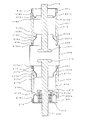
以下、この発明の実施の形態1を図1に基づいて説明する。図1はこの発明の実施の形態1に係わる真空バルブを示す断面図である。
A first embodiment of the present invention will be described below with reference to FIG. 1 is a sectional view showing a vacuum valve according to
図1において、101はセラミックからなる筒状の絶縁容器であり、例えば中央部で連結された2個の絶縁容器101a,101bで構成された場合を示している。102は絶縁容器101aの一方側となる端部を塞ぐ固定側端板、103は絶縁容器101bの一方側となる端部を塞ぐ可動側端板であり、これら固定側端板102、絶縁容器101a,101b、可動側端板103とにより真空容器が構成される。
In FIG. 1,
104は固定側端板102を貫通して配設された固定側通電軸、105は可動側端板103を貫通してベローズ106を介して配設された可動側通電軸、107は絶縁容器101内に位置する固定側通電軸104の先端部に設けられた固定側電極、108は絶縁容器101内に位置する可動側通電軸105の先端部に固定側電極107と相対向して設けられた可動側電極である。
109aおよび109bは少なくとも絶縁容器101aの固定側の端部101a1および絶縁容器101bの可動側の端部101b1の後述する第1の電界緩和シールドおよび第2の電界緩和シールドの配置スペースを残してそれら端部101a1,101b1側内周面より内周側に突出する例えば10〜25度のテーパ部109a1,109a2,109b1,109b2を有する段部である。図は一例として、2個の絶縁容器101a,101bの両端部よりテーパ状に形成された段部109a,109bの場合を示している。この段部109a,109bにより絶縁容器101a,101bの肉厚を大きく構成して貫通破壊に耐える肉厚を確保している。
Reference numerals 109a and 109b denote at least the fixed-side end 101a1 of the insulating container 101a and the movable-side end 101b1 of the
110aおよび110bは絶縁容器101a,101b内で固定側電極107と可動側電極108の周囲を囲繞するように配設された第1のアークシールドおよび第2のアークシールドであり、電流遮断時、固定側電極107と可動側電極108との間で発生したアークが直接セラミックからなる絶縁容器101a,101bの内面に接触するのを防いでいる。これら第1のアークシールド110aおよび第2のアークシールド110bは、絶縁容器101a,101bを2個使って、中間部で支持することにより、両電極から電気的に絶縁されている。
110a and 110b are a first arc shield and a second arc shield disposed so as to surround the fixed
また、第1のアークシールド110aおよび第2のアークシールド110bは、その支持部110a1,110b1は絶縁容器101a,101bと平行してのび、この支持部110a1,110b1と連続してのびる端部110a2,110b2は絶縁容器101a,101bの内面から離れるように起点部110a3,110b3を起点として10〜25度の傾斜を持って延びており、これら端部110a2,110b2は段部109a,109bのある範囲内に配置されている。
Further, the first arc shield 110a and the second arc shield 110b have support portions 110a1 and 110b1 extending in parallel with the
111は固定側端板102に取り付けられ、絶縁容器101aの固定側の端部101a1側に第1のアークシールド110aと相対向するように配置された第1の電界緩和シールドであり、絶縁容器101aの端部封着部を電界緩和するために設けられている。そして、第1のアークシールド110aと相対向する第1の電界緩和シールド111は、平行部111aから絶縁容器101aの内面から離れるように例えば10〜25度の傾斜部111bを持ち、先端部111cは絶縁容器101aに設けた段部109aより内径側に配置され、その端部をリング状に丸めている。また、第1の電界緩和シールド111の傾斜部111bは、段部109aのテーパ部109a1と相対応された配置となっており、それらの傾斜角度は概ね平行に設定されているが多少の傾斜角度の相違は許容される。
112は可動側端板103に取り付けられ、絶縁容器101bの可動側の端部101b1側に第2のアークシールド110bと相対向するように配置された第2の電界緩和シールドであり、絶縁容器101bの端部封着部を電界緩和するために設けられている。そして、第2のアークシールド110bと相対向する第2の電界緩和シールド112は、平行部112aから絶縁容器101bの内面から離れるように例えば10〜25度の傾斜部112bを持ち、先端部112cは絶縁容器101bに設けた段部109bより内径側に配置され、その端部をリング状に丸めている。また、第2の電界緩和シールド112の傾斜部112bは、段部109bのテーパ部109b1と相対応された配置となっており、それらの傾斜角度は概ね平行に設定されているが多少の傾斜角度の相違は許容される。
113はペローズシールドであり、114は絶縁容器101aと絶縁容器101bとを封着する封着部材であり、例えばリング状に形成され、リング状の内周側に第1のアークシールド110aおよび第2のアークシールド110bが取り付けられている。
113 is a bellows shield, and 114 is a sealing member for sealing the insulating container 101a and the insulating
以上のように構成されたこの実施の形態1における真空バルブでは、第1の電界緩和シールド111および第2の電界緩和シールド112の無い部分にテーパ部109a1,109a2,109b1,109b2を有する段部109a,109bを設けているので、真空バルブの外径を大形化することなくセラミックからなる絶縁容器101a,101bの肉厚を大きく構成することができる。
In the vacuum valve according to the first embodiment configured as described above, the step portion 109a having the tapered portions 109a1, 109a2, 109b1, and 109b2 in the portions where the first electric
また、第1の電界緩和シールド111および第2の電界緩和シールド112の先端部111c,112cは絶縁容器101a,101bの段部109a,109bより内径側に配置しているので、段部109a,109bとの距離を確保することができ、絶縁性能をより一層高くすることができる。
Moreover, since the front-end | tip parts 111c and 112c of the 1st electric
更に、絶縁容器101a,101bの段部109a,109bのテーパ部109a1,101b1に、第1の電界緩和シールド111および第2の電界緩和シールド112の傾斜部111b,112bを対応させているので、段部109a,109bのテーパ部109a1,109b1と第1の電界緩和シールド111および第2の電界緩和シールド112の傾斜部111c,112cとの距離を全体にわたって均一にすることができ、絶縁性能の弱点部の形成を防止することができる。
Further, the tapered portions 109a1 and 101b1 of the step portions 109a and 109b of the insulating
また、第1のアークシールド110aおよび第2のアークシールド110bの端部110a2,110b2は絶縁容器101a,101bの段部109a,109bがある範囲内に配置しているので、第1のアークシールド110aおよび第2のアークシールド110bの端部110a2,110b2先端からのアークは段部109a,109bの肉厚な部分に飛ぶようになるので貫通破壊を防ぐことができる。
In addition, since the end portions 110a2 and 110b2 of the first arc shield 110a and the second arc shield 110b are disposed within a certain range of the step portions 109a and 109b of the insulating
以上のように、この発明では真空バルブの外径を大形化することなく、より高い電圧で電圧コンディショニングを行うことができることで、電圧コンディショニング工程の時間短縮を図ることができ、耐電圧性能の信頼性がより一層高い安価な真空バルブを提供することができる。 As described above, according to the present invention, voltage conditioning can be performed at a higher voltage without increasing the outer diameter of the vacuum valve, so that the time required for the voltage conditioning process can be shortened and the withstand voltage performance can be improved. An inexpensive vacuum valve with higher reliability can be provided.
実施の形態2.
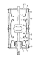
この発明の実施の形態2を図2に基づいて説明する。図2はこの発明の実施の形態2に係わる真空バルブを示す断面図である。
A second embodiment of the present invention will be described with reference to FIG. 2 is a cross-sectional view showing a vacuum valve according to
上述した実施の形態1においては、絶縁容器は2個に分割された絶縁容器101aと絶縁容器101bとにより構成された場合について述べたが、一体構造体からなる絶縁容器101であってもよい。また、アークシールドも2個に分割された第1のアークシールド110aと第2のアークシールド110bとにより構成された場合について述べたが、一体構造体からなるアークシールド110であってもよい。
In
すなわち、図2に示すように、一体構造体からなる絶縁容器101はその両端に端部101a1,101b1がそれぞれ設けられ、それら端部101a1,101b1側内周面より内周側に突出する例えば10〜25度のテーパ部109a1,109b1を有する段部109が形成されている。また、一体構造体からなるアークシールド110は支持部材115により絶縁容器101に取り付けられている。
That is, as shown in FIG. 2, the insulating
この実施の形態2によれば、絶縁容器101およびアークシールド110を一体構造体として構成したものであり、上述した実施の形態1と同様の効果を奏するとともに、構成体の簡素化を図ることができる。
According to the second embodiment, the insulating
実施の形態3.
この発明の実施の形態3を図3に基づいて説明する。図3はこの発明の実施の形態3に係わる真空バルブを示す断面図である。
A third embodiment of the present invention will be described with reference to FIG. 3 is a sectional view showing a vacuum valve according to
上述した実施の形態1,2においては、第1の電界緩和シールド111および第2の電界緩和シールド112の先端部111c,112cがリング状に丸めて形成された場合について述べたが、この実施の形態3においては、第1の電界緩和シールド111および第2の電界緩和シールド112の先端部111d,112dにはリング状に丸めた形状に形成していないものである。
In the first and second embodiments described above, the case where the tip portions 111c and 112c of the first electric
この実施の形態3によれば、上述した実施の形態1,2と同様の効果を奏するとともに、第1の電界緩和シールド111および第2の電界緩和シールド112の形成作業が容易となり、製造コストの低減化を図ることができる。
According to the third embodiment, the same effects as those of the first and second embodiments described above can be obtained, and the first electric
実施の形態4.
この発明の実施の形態4を図4に基づいて説明する。図4はこの発明の実施の形態4に係わる真空バルブを示す断面図である。
図4において、201はセラミックからなる筒状の第1の絶縁容器、202はセラミックからなる筒状の第2の絶縁容器、203は第1の絶縁容器201の一方側となる端部201aを塞ぐ固定側端板、204は第2の絶縁容器202の一方側となる端部202aを塞ぐ可動側端板、205は第1の絶縁容器201の他方側なる端部201bと第2の絶縁容器202の他方側となる端部202bとの間に配設された金属容器(またはシリンダー)であり、これら固定側端板102、第1の絶縁容器201、金属容器(またはシリンダー)205、第2の絶縁容器202、可動側端板103とにより真空容器が構成される。なお、第1の絶縁容器201と金属容器(またはシリンダー)205とは封着部材206により一体的に接続され、金属容器(またはシリンダー)205と第2の絶縁容器202とは封着部材207により一体的に接続されている。
In FIG. 4, 201 is a cylindrical first insulating container made of ceramic, 202 is a cylindrical second insulating container made of ceramic, and 203 closes an end 201 a which is one side of the first insulating
208は固定側端板203を貫通して配設された固定側通電軸、209は可動側端板204を貫通してベローズ210を介して配設された可動側通電軸、211は金属容器(またはシリンダー)205内に位置する固定側通電軸208の先端部に設けられた固定側電極、212は第3の絶縁容器205内に位置する可動側通電軸209の先端部に固定側電極211と相対向して設けられた可動側電極である。
208 is a fixed energizing shaft disposed through the
213は少なくとも第1の絶縁容器201の固定側の端部201aの後述する第1の電界緩和シールドの配置スペースを残して端部201a側内周面より内周側に突出する例えば10〜25度のテーパ部213a,213bを有する第1の段部である。この第1の段部213により第1の絶縁容器201の肉厚を大きく構成して貫通破壊に耐える肉厚を確保している。
Reference numeral 213 denotes, for example, 10 to 25 degrees that protrudes from the inner peripheral surface of the end portion 201a side to the inner peripheral side, leaving a space for arranging a first electric field relaxation shield (described later) of the end portion 201a on the fixed side of the first insulating
214は少なくとも第2の絶縁容器202の可動側の端部202aの後述する第2の電界緩和シールドの配置スペースを残して端部202a側内周面より内周側に突出する例えば10〜25度のテーパ部214a,214bを有する第2の段部である。この第2の段部214により第2の絶縁容器202の肉厚を大きく構成して貫通破壊に耐える肉厚を確保している。215はベローズシールドである。
216は一方側の端部216aが金属容器(またはシリンダー)205に接続され、他方側の端部216bは第1の段部213のある範囲内に配置された第1のアークシールドであり、図は一例として、第1のアークシールド216の端部216a側は第1の絶縁容器201と平行してのび、起点部216cを起点として10〜25度の傾斜を持って第1の絶縁容器201の内面から離れるように延びる傾斜部216dが形成され、傾斜部216dの起点部216eを起点として端部216b側が第1の絶縁容器201と平行に配置されている。また、第1のアークシールド216の傾斜部216dは、第1の段部213のテーパ部213bと相対応された配置となっており、それらの傾斜角度は概ね平行に設定されているが多少の傾斜角度の相違は許容される。
217は一方側の端部217aが金属容器(またはシリンダー)205に接続され、他方側の端部217bは第2の段部214のある範囲内に配置された第2のアークシールドであり、図は一例として、第2のアークシールド217の端部217a側は第2の絶縁容器202と平行してのび、起点部217cを起点として10〜25度の傾斜を持って第2の絶縁容器202の内面から離れるように延びる傾斜部217dが形成され、傾斜部217dの起点部217eを起点として端部217b側が第2の絶縁容器202と平行に配置されている。また、第2のアークシールド217の傾斜部217dは、第2の段部214のテーパ部214bと相対応された配置となっており、それらの傾斜角度は概ね平行に設定されているが多少の傾斜角度の相違は許容される。
218は固定側端板203に取り付けられ、第1の絶縁容器201の固定側の端部201a側に第1のアークシールド216と相対向するように配置された第1の電界緩和シールドであり、第1の絶縁容器201の端部封着部を電界緩和するために設けられている。そして、第1のアークシールド216と相対向する第1の電界緩和シールド218は、平行部218aから第1の絶縁容器201の内面から離れるように例えば10〜25度の傾斜部218bを持ち、先端部218cは第1の絶縁容器201に設けた第1の段部213より内径側に配置され、その端部をリング状に丸めている。また、第1の電界緩和シールド218の傾斜部218bは、第1の段部213のテーパ部213aと相対応された配置となっており、それらの傾斜角度は概ね平行に設定されているが多少の傾斜角度の相違は許容される。
218 is a first electric field relaxation shield that is attached to the fixed
219は可動側端板204に取り付けられ、第2の絶縁容器202の可動側の端部202a側に第2のアークシールド217と相対向するように配置された第2の電界緩和シールドであり、第2の絶縁容器202の端部封着部を電界緩和するために設けられている。そして、第2のアークシールド217と相対向する第2の電界緩和シールド219は、平行部219aから第2の絶縁容器202の内面から離れるように例えば10〜25度の傾斜部219bを持ち、先端部219cは第2の絶縁容器202に設けた第2の段部214より内径側に配置され、その端部をリング状に丸めている。また、第2の電界緩和シールド219の傾斜部219bは、第2の段部214のテーパ部214aと相対応された配置となっており、それらの傾斜角度は概ね平行に設定されているが多少の傾斜角度の相違は許容される。
219 is a second electric field relaxation shield that is attached to the movable
以上のように構成されたこの実施の形態4における真空バルブでは、第1の電界緩和シールド218および第2の電界緩和シールド219の無い部分にテーパ部213a,214b,214a,214bを有する第1の段部213および第2の段部214を設けているので、真空バルブの外径を大形化することなくセラミックからなる第1の絶縁容器201および第2の絶縁容器202の肉厚を大きく構成することができる。
In the vacuum valve according to the fourth embodiment configured as described above, the first electric
また、第1の電界緩和シールド218および第2の電界緩和シールド219の先端部218c,219cは第1の絶縁容器201および第2の絶縁容器202の第1の段部213および第2の段部214より内径側に配置しているので、第1の段部213および第2の段部214との距離を確保することができ、絶縁性能をより一層高くすることができる。なお、第1の電界緩和シールド218および第2の電界緩和シールド219の先端部218c,219cはリング状に丸めた形状としているが、必ずしもリング状に形成することはなく、上述した図3に示すような簡素な形状とすることもできる。
Further, the tip portions 218c and 219c of the first electric
更に、第1の絶縁容器201および第2の絶縁容器202の第1の段部213および第2の段部214のテーパ部213a,214aに、第1の電界緩和シールド218および第2の電界緩和シールド219の傾斜部218b,219bを対応させているので、第1の段部213および第2の段部214のテーパ部213a,214aと第1の電界緩和シールド218および第2の電界緩和シールド219の傾斜部218c,219cとの距離を全体にわたって均一にすることができ、絶縁性能の弱点部の形成を防止することができる。
Furthermore, the first electric
ところで、この実施の形態4においては、固定側電極211および可動側電極212は金属容器(またはシリンダー)205内に配設され、第1の絶縁容器201および第2の絶縁容器202により両電極から電気的に絶縁されており、金属容器(またはシリンダー)205は浮遊電位(中間電位)となる。金属容器(またはシリンダー)205の外側に絶縁容器を配さないため、真空バルブはさらに小形化できる。
また、金属容器(またはシリンダー)205の電位は30〜70%程度となるため、金属容器(またはシリンダー)205は固定側端板203および可動側端板204より外形が大きくなってもよい。
By the way, in the fourth embodiment, the fixed side electrode 211 and the movable side electrode 212 are disposed in the metal container (or cylinder) 205, and the first insulating
Further, since the potential of the metal container (or cylinder) 205 is about 30 to 70%, the outer shape of the metal container (or cylinder) 205 may be larger than that of the fixed
また、第1のアークシールド216および第2のアークシールド217の端部216b,217bは第1の絶縁容器201および第2の絶縁容器202の第1の段部213および第2の段部214がある範囲内に配置しているので、第1のアークシールド216および第2のアークシールド217の端部216b,217b先端からのアークは第1の段部213および第2の段部214の肉厚な部分に飛ぶようになるので貫通破壊を防ぐことができる。
Further, the end portions 216b and 217b of the
以上のように、この発明では真空バルブの外径を上述した各実施の形態よりもさらに小型化を図ることができ、より高い電圧で電圧コンディショニングを行うことができることで、電圧コンディショニング工程の時間短縮を図ることができ、耐電圧性能の信頼性がより一層高い安価な真空バルブを提供することができる。 As described above, according to the present invention, the outer diameter of the vacuum valve can be further reduced as compared with each of the above-described embodiments, and voltage conditioning can be performed at a higher voltage, thereby shortening the time of the voltage conditioning process. Therefore, it is possible to provide an inexpensive vacuum valve with higher reliability of withstand voltage performance.
この発明は、大形化することなく絶縁性能の向上を図ることができる真空バルブの実現に好適である。 The present invention is suitable for realizing a vacuum valve capable of improving the insulation performance without increasing the size.
101 絶縁容器
101a 絶縁容器
101b 絶縁容器
101a1 端部
101b1 端部
102 固定側端板
103 可動側端板
104 固定側通電軸
105 可動側通電軸
107 固定側電極
108 可動側電極
109 段部
109a 段部
109b 段部
109a1 テーパ部
109b1 テーパ部
110 アークシールド
110a アークシールド
110b アークシールド
110a2 端部
110b2 端部
111 第1の電界緩和シールド
111b 傾斜部
111c 先端部
112 第2の電界緩和シールド
112b 傾斜部
112c 先端部
201 第1の絶縁容器
201a 端部
201b 端部
202 第2の絶縁容器
202a 端部
202b 端部
203 固定側端板
204 可動側端板
205 金属容器
208 固定側通電軸
209 可動側通電軸
211 固定側電極
212 可動側電極
213 第1の段部
213a テーパ部
213b テーパ部
214 第2の段部
214a テーパ部
214b テーパ部
216 第1のアークシールド
216a 端部
216b 端部
216d テーパ部
217 第2のアークシールド
217a 端部
217b 端部
217d テーパ部
218 第1の電界緩和シールド
218b 傾斜部
218c 先端部
219 第2の電界緩和シールド
219b 傾斜部
219c 先端部
DESCRIPTION OF
Claims (9)
Priority Applications (1)
| Application Number | Priority Date | Filing Date | Title |
|---|---|---|---|
| JP2011220707A JP5851187B2 (en) | 2011-10-05 | 2011-10-05 | Vacuum valve |
Applications Claiming Priority (1)
| Application Number | Priority Date | Filing Date | Title |
|---|---|---|---|
| JP2011220707A JP5851187B2 (en) | 2011-10-05 | 2011-10-05 | Vacuum valve |
Publications (3)
| Publication Number | Publication Date |
|---|---|
| JP2013080647A JP2013080647A (en) | 2013-05-02 |
| JP2013080647A5 JP2013080647A5 (en) | 2014-07-31 |
| JP5851187B2 true JP5851187B2 (en) | 2016-02-03 |
Family
ID=48526869
Family Applications (1)
| Application Number | Title | Priority Date | Filing Date |
|---|---|---|---|
| JP2011220707A Active JP5851187B2 (en) | 2011-10-05 | 2011-10-05 | Vacuum valve |
Country Status (1)
| Country | Link |
|---|---|
| JP (1) | JP5851187B2 (en) |
Families Citing this family (1)
| Publication number | Priority date | Publication date | Assignee | Title |
|---|---|---|---|---|
| FR3066311A1 (en) * | 2017-05-15 | 2018-11-16 | Schneider Electric Industries Sas | DEVICE FOR CENTERING A METAL SCREEN IN A VACUUM BULB, AND VACUUM BULB COMPRISING SUCH A DEVICE |
Family Cites Families (4)
| Publication number | Priority date | Publication date | Assignee | Title |
|---|---|---|---|---|
| JPS5917541U (en) * | 1982-07-26 | 1984-02-02 | 株式会社明電舎 | vacuum interrupter |
| JPS5939846U (en) * | 1982-09-08 | 1984-03-14 | 株式会社東芝 | vacuum valve |
| JPH06101283B2 (en) * | 1987-07-15 | 1994-12-12 | 三菱電機株式会社 | Ceramic insulation container for high-voltage vacuum discharge device |
| JP2003317583A (en) * | 2002-04-24 | 2003-11-07 | Mitsubishi Electric Corp | Vacuum valve |
-
2011
- 2011-10-05 JP JP2011220707A patent/JP5851187B2/en active Active
Also Published As
| Publication number | Publication date |
|---|---|
| JP2013080647A (en) | 2013-05-02 |
Similar Documents
| Publication | Publication Date | Title |
|---|---|---|
| JP5111623B2 (en) | Contact device | |
| JP2003536221A (en) | Vacuum valve with two contact devices | |
| EP2485235B1 (en) | Vacuum interrupter for vacuum circuit breaker | |
| JP6296153B2 (en) | Power storage device | |
| JP2021526707A (en) | Top lid assembly and rechargeable battery | |
| EP3378084B1 (en) | Maximizing wall thickness of a cu-cr floating center shield component by moving contact gap away from center flange axial location | |
| US10741821B2 (en) | Secondary battery | |
| JP5243575B2 (en) | Vacuum circuit breaker | |
| JP5851187B2 (en) | Vacuum valve | |
| JP6029524B2 (en) | Switchgear | |
| CN1178254C (en) | Vacuum interrupter chamber with ying-shaped insulator | |
| JP5197065B2 (en) | Vacuum valve | |
| JP2013062471A (en) | Ignition coil for internal combustion engine | |
| JP2014007081A (en) | Vacuum valve | |
| JP4818530B2 (en) | Vacuum valve | |
| US9496106B2 (en) | Electrode assembly and vacuum interrupter including the same | |
| JP2007115599A (en) | Vacuum valve | |
| JP2007280668A (en) | Spark plug | |
| JPH01294355A (en) | Cylindrical battery | |
| JP2001356109A (en) | Gas sensor | |
| JP5537303B2 (en) | Vacuum valve | |
| JPWO2011117914A1 (en) | Vacuum valve and switchgear equipped with the vacuum valve | |
| JP2005149899A (en) | Vacuum valve | |
| JP2006344557A (en) | Vacuum valve and conditioning treatment method | |
| JP2006286327A (en) | Spark plug |
Legal Events
| Date | Code | Title | Description |
|---|---|---|---|
| A521 | Request for written amendment filed |
Free format text: JAPANESE INTERMEDIATE CODE: A523 Effective date: 20140618 |
|
| A621 | Written request for application examination |
Free format text: JAPANESE INTERMEDIATE CODE: A621 Effective date: 20140618 |
|
| A131 | Notification of reasons for refusal |
Free format text: JAPANESE INTERMEDIATE CODE: A131 Effective date: 20150317 |
|
| A977 | Report on retrieval |
Free format text: JAPANESE INTERMEDIATE CODE: A971007 Effective date: 20150319 |
|
| A521 | Request for written amendment filed |
Free format text: JAPANESE INTERMEDIATE CODE: A523 Effective date: 20150417 |
|
| A131 | Notification of reasons for refusal |
Free format text: JAPANESE INTERMEDIATE CODE: A131 Effective date: 20150915 |
|
| A521 | Request for written amendment filed |
Free format text: JAPANESE INTERMEDIATE CODE: A523 Effective date: 20151006 |
|
| TRDD | Decision of grant or rejection written | ||
| A01 | Written decision to grant a patent or to grant a registration (utility model) |
Free format text: JAPANESE INTERMEDIATE CODE: A01 Effective date: 20151104 |
|
| A61 | First payment of annual fees (during grant procedure) |
Free format text: JAPANESE INTERMEDIATE CODE: A61 Effective date: 20151202 |
|
| R151 | Written notification of patent or utility model registration |
Ref document number: 5851187 Country of ref document: JP Free format text: JAPANESE INTERMEDIATE CODE: R151 |
|
| R250 | Receipt of annual fees |
Free format text: JAPANESE INTERMEDIATE CODE: R250 |
|
| R250 | Receipt of annual fees |
Free format text: JAPANESE INTERMEDIATE CODE: R250 |
|
| R250 | Receipt of annual fees |
Free format text: JAPANESE INTERMEDIATE CODE: R250 |
|
| R250 | Receipt of annual fees |
Free format text: JAPANESE INTERMEDIATE CODE: R250 |
|
| R250 | Receipt of annual fees |
Free format text: JAPANESE INTERMEDIATE CODE: R250 |
|
| R250 | Receipt of annual fees |
Free format text: JAPANESE INTERMEDIATE CODE: R250 |