JP5850506B2 - Golf ball core mold plate and mold forming method - Google Patents
Golf ball core mold plate and mold forming method Download PDFInfo
- Publication number
- JP5850506B2 JP5850506B2 JP2013092695A JP2013092695A JP5850506B2 JP 5850506 B2 JP5850506 B2 JP 5850506B2 JP 2013092695 A JP2013092695 A JP 2013092695A JP 2013092695 A JP2013092695 A JP 2013092695A JP 5850506 B2 JP5850506 B2 JP 5850506B2
- Authority
- JP
- Japan
- Prior art keywords
- mold
- mold plate
- plate
- protrusion
- movable insert
- Prior art date
- Legal status (The legal status is an assumption and is not a legal conclusion. Google has not performed a legal analysis and makes no representation as to the accuracy of the status listed.)
- Active
Links
- 238000000034 method Methods 0.000 title claims description 38
- 239000002893 slag Substances 0.000 claims description 63
- 238000000465 moulding Methods 0.000 claims description 54
- 239000000463 material Substances 0.000 claims description 49
- 239000011248 coating agent Substances 0.000 claims description 11
- 238000000576 coating method Methods 0.000 claims description 11
- 238000004519 manufacturing process Methods 0.000 claims description 11
- 239000003795 chemical substances by application Substances 0.000 claims description 2
- 238000003825 pressing Methods 0.000 claims 1
- 239000011162 core material Substances 0.000 description 149
- 239000010410 layer Substances 0.000 description 27
- 229920001577 copolymer Polymers 0.000 description 23
- -1 diallyl phthalic acid Chemical compound 0.000 description 18
- 229920000554 ionomer Polymers 0.000 description 15
- 230000006835 compression Effects 0.000 description 14
- 238000007906 compression Methods 0.000 description 14
- 229920000642 polymer Polymers 0.000 description 12
- 238000000748 compression moulding Methods 0.000 description 10
- 239000000203 mixture Substances 0.000 description 7
- 229920001897 terpolymer Polymers 0.000 description 7
- PPBRXRYQALVLMV-UHFFFAOYSA-N Styrene Natural products C=CC1=CC=CC=C1 PPBRXRYQALVLMV-UHFFFAOYSA-N 0.000 description 6
- 229920001971 elastomer Polymers 0.000 description 6
- 229920005989 resin Polymers 0.000 description 5
- 239000011347 resin Substances 0.000 description 5
- 229920001187 thermosetting polymer Polymers 0.000 description 5
- 239000004711 α-olefin Substances 0.000 description 5
- LIKMAJRDDDTEIG-UHFFFAOYSA-N 1-hexene Chemical compound CCCCC=C LIKMAJRDDDTEIG-UHFFFAOYSA-N 0.000 description 4
- VZCYOOQTPOCHFL-OWOJBTEDSA-N Fumaric acid Chemical compound OC(=O)\C=C\C(O)=O VZCYOOQTPOCHFL-OWOJBTEDSA-N 0.000 description 4
- 239000004952 Polyamide Substances 0.000 description 4
- 239000005062 Polybutadiene Substances 0.000 description 4
- XUIMIQQOPSSXEZ-UHFFFAOYSA-N Silicon Chemical compound [Si] XUIMIQQOPSSXEZ-UHFFFAOYSA-N 0.000 description 4
- 239000002253 acid Substances 0.000 description 4
- 125000003342 alkenyl group Chemical group 0.000 description 4
- 125000004432 carbon atom Chemical group C* 0.000 description 4
- 125000003700 epoxy group Chemical group 0.000 description 4
- 229920002647 polyamide Polymers 0.000 description 4
- 229920002857 polybutadiene Polymers 0.000 description 4
- 239000005060 rubber Substances 0.000 description 4
- VZCYOOQTPOCHFL-UHFFFAOYSA-N trans-butenedioic acid Natural products OC(=O)C=CC(O)=O VZCYOOQTPOCHFL-UHFFFAOYSA-N 0.000 description 4
- 229920002943 EPDM rubber Polymers 0.000 description 3
- OFOBLEOULBTSOW-UHFFFAOYSA-N Malonic acid Chemical compound OC(=O)CC(O)=O OFOBLEOULBTSOW-UHFFFAOYSA-N 0.000 description 3
- MUBZPKHOEPUJKR-UHFFFAOYSA-N Oxalic acid Chemical compound OC(=O)C(O)=O MUBZPKHOEPUJKR-UHFFFAOYSA-N 0.000 description 3
- 230000009977 dual effect Effects 0.000 description 3
- 239000012778 molding material Substances 0.000 description 3
- 229920001296 polysiloxane Polymers 0.000 description 3
- 238000007493 shaping process Methods 0.000 description 3
- 229910052710 silicon Inorganic materials 0.000 description 3
- 239000010703 silicon Substances 0.000 description 3
- 239000002210 silicon-based material Substances 0.000 description 3
- 150000007934 α,β-unsaturated carboxylic acids Chemical class 0.000 description 3
- PBLZLIFKVPJDCO-UHFFFAOYSA-N 12-aminododecanoic acid Chemical compound NCCCCCCCCCCCC(O)=O PBLZLIFKVPJDCO-UHFFFAOYSA-N 0.000 description 2
- SMZOUWXMTYCWNB-UHFFFAOYSA-N 2-(2-methoxy-5-methylphenyl)ethanamine Chemical compound COC1=CC=C(C)C=C1CCN SMZOUWXMTYCWNB-UHFFFAOYSA-N 0.000 description 2
- JAHNSTQSQJOJLO-UHFFFAOYSA-N 2-(3-fluorophenyl)-1h-imidazole Chemical compound FC1=CC=CC(C=2NC=CN=2)=C1 JAHNSTQSQJOJLO-UHFFFAOYSA-N 0.000 description 2
- NIXOWILDQLNWCW-UHFFFAOYSA-N 2-Propenoic acid Natural products OC(=O)C=C NIXOWILDQLNWCW-UHFFFAOYSA-N 0.000 description 2
- SZTBMYHIYNGYIA-UHFFFAOYSA-N 2-chloroacrylic acid Chemical compound OC(=O)C(Cl)=C SZTBMYHIYNGYIA-UHFFFAOYSA-N 0.000 description 2
- WROUWQQRXUBECT-UHFFFAOYSA-N 2-ethylacrylic acid Chemical compound CCC(=C)C(O)=O WROUWQQRXUBECT-UHFFFAOYSA-N 0.000 description 2
- 125000003903 2-propenyl group Chemical group [H]C([*])([H])C([H])=C([H])[H] 0.000 description 2
- 229920002633 Kraton (polymer) Polymers 0.000 description 2
- JHWNWJKBPDFINM-UHFFFAOYSA-N Laurolactam Chemical compound O=C1CCCCCCCCCCCN1 JHWNWJKBPDFINM-UHFFFAOYSA-N 0.000 description 2
- 229920000106 Liquid crystal polymer Polymers 0.000 description 2
- 239000004977 Liquid-crystal polymers (LCPs) Substances 0.000 description 2
- CERQOIWHTDAKMF-UHFFFAOYSA-N Methacrylic acid Chemical compound CC(=C)C(O)=O CERQOIWHTDAKMF-UHFFFAOYSA-N 0.000 description 2
- BAPJBEWLBFYGME-UHFFFAOYSA-N Methyl acrylate Chemical compound COC(=O)C=C BAPJBEWLBFYGME-UHFFFAOYSA-N 0.000 description 2
- 229920002396 Polyurea Polymers 0.000 description 2
- KKEYFWRCBNTPAC-UHFFFAOYSA-N Terephthalic acid Chemical compound OC(=O)C1=CC=C(C(O)=O)C=C1 KKEYFWRCBNTPAC-UHFFFAOYSA-N 0.000 description 2
- 238000009825 accumulation Methods 0.000 description 2
- WNLRTRBMVRJNCN-UHFFFAOYSA-N adipic acid Chemical compound OC(=O)CCCCC(O)=O WNLRTRBMVRJNCN-UHFFFAOYSA-N 0.000 description 2
- 230000002411 adverse Effects 0.000 description 2
- 125000001931 aliphatic group Chemical group 0.000 description 2
- 125000000217 alkyl group Chemical group 0.000 description 2
- VHRGRCVQAFMJIZ-UHFFFAOYSA-N cadaverine Chemical compound NCCCCCN VHRGRCVQAFMJIZ-UHFFFAOYSA-N 0.000 description 2
- 125000003178 carboxy group Chemical group [H]OC(*)=O 0.000 description 2
- 150000001735 carboxylic acids Chemical class 0.000 description 2
- 150000001768 cations Chemical class 0.000 description 2
- LDHQCZJRKDOVOX-NSCUHMNNSA-N crotonic acid Chemical compound C\C=C\C(O)=O LDHQCZJRKDOVOX-NSCUHMNNSA-N 0.000 description 2
- 150000004985 diamines Chemical class 0.000 description 2
- 239000000806 elastomer Substances 0.000 description 2
- JBKVHLHDHHXQEQ-UHFFFAOYSA-N epsilon-caprolactam Chemical compound O=C1CCCCCN1 JBKVHLHDHHXQEQ-UHFFFAOYSA-N 0.000 description 2
- 239000005038 ethylene vinyl acetate Substances 0.000 description 2
- 239000001530 fumaric acid Substances 0.000 description 2
- NAQMVNRVTILPCV-UHFFFAOYSA-N hexane-1,6-diamine Chemical compound NCCCCCCN NAQMVNRVTILPCV-UHFFFAOYSA-N 0.000 description 2
- 150000002430 hydrocarbons Chemical class 0.000 description 2
- 238000001746 injection moulding Methods 0.000 description 2
- QQVIHTHCMHWDBS-UHFFFAOYSA-N isophthalic acid Chemical compound OC(=O)C1=CC=CC(C(O)=O)=C1 QQVIHTHCMHWDBS-UHFFFAOYSA-N 0.000 description 2
- VZCYOOQTPOCHFL-UPHRSURJSA-N maleic acid Chemical compound OC(=O)\C=C/C(O)=O VZCYOOQTPOCHFL-UPHRSURJSA-N 0.000 description 2
- 239000011976 maleic acid Substances 0.000 description 2
- 229910021645 metal ion Inorganic materials 0.000 description 2
- LVHBHZANLOWSRM-UHFFFAOYSA-N methylenebutanedioic acid Natural products OC(=O)CC(=C)C(O)=O LVHBHZANLOWSRM-UHFFFAOYSA-N 0.000 description 2
- 239000000178 monomer Substances 0.000 description 2
- 238000006386 neutralization reaction Methods 0.000 description 2
- 229920001200 poly(ethylene-vinyl acetate) Polymers 0.000 description 2
- 238000006068 polycondensation reaction Methods 0.000 description 2
- 229920000728 polyester Polymers 0.000 description 2
- 229920001195 polyisoprene Polymers 0.000 description 2
- 229920000098 polyolefin Polymers 0.000 description 2
- 229920001955 polyphenylene ether Polymers 0.000 description 2
- 229920002635 polyurethane Polymers 0.000 description 2
- 239000004814 polyurethane Substances 0.000 description 2
- KIDHWZJUCRJVML-UHFFFAOYSA-N putrescine Chemical compound NCCCCN KIDHWZJUCRJVML-UHFFFAOYSA-N 0.000 description 2
- CXMXRPHRNRROMY-UHFFFAOYSA-N sebacic acid Chemical compound OC(=O)CCCCCCCCC(O)=O CXMXRPHRNRROMY-UHFFFAOYSA-N 0.000 description 2
- 238000000926 separation method Methods 0.000 description 2
- 239000007787 solid Substances 0.000 description 2
- 229920003051 synthetic elastomer Polymers 0.000 description 2
- 239000005061 synthetic rubber Substances 0.000 description 2
- LDHQCZJRKDOVOX-UHFFFAOYSA-N trans-crotonic acid Natural products CC=CC(O)=O LDHQCZJRKDOVOX-UHFFFAOYSA-N 0.000 description 2
- PXGZQGDTEZPERC-UHFFFAOYSA-N 1,4-cyclohexanedicarboxylic acid Chemical compound OC(=O)C1CCC(C(O)=O)CC1 PXGZQGDTEZPERC-UHFFFAOYSA-N 0.000 description 1
- GUOSQNAUYHMCRU-UHFFFAOYSA-N 11-Aminoundecanoic acid Chemical compound NCCCCCCCCCCC(O)=O GUOSQNAUYHMCRU-UHFFFAOYSA-N 0.000 description 1
- QTWJRLJHJPIABL-UHFFFAOYSA-N 2-methylphenol;3-methylphenol;4-methylphenol Chemical compound CC1=CC=C(O)C=C1.CC1=CC=CC(O)=C1.CC1=CC=CC=C1O QTWJRLJHJPIABL-UHFFFAOYSA-N 0.000 description 1
- 125000000094 2-phenylethyl group Chemical group [H]C1=C([H])C([H])=C(C([H])=C1[H])C([H])([H])C([H])([H])* 0.000 description 1
- PYSRRFNXTXNWCD-UHFFFAOYSA-N 3-(2-phenylethenyl)furan-2,5-dione Chemical compound O=C1OC(=O)C(C=CC=2C=CC=CC=2)=C1 PYSRRFNXTXNWCD-UHFFFAOYSA-N 0.000 description 1
- LIMIJVKKNPAMJE-UHFFFAOYSA-N 5-phenylpenta-2,4-dienenitrile prop-2-enenitrile Chemical compound C=CC#N.N#CC=CC=Cc1ccccc1 LIMIJVKKNPAMJE-UHFFFAOYSA-N 0.000 description 1
- SLXKOJJOQWFEFD-UHFFFAOYSA-N 6-aminohexanoic acid Chemical compound NCCCCCC(O)=O SLXKOJJOQWFEFD-UHFFFAOYSA-N 0.000 description 1
- VWPQCOZMXULHDM-UHFFFAOYSA-N 9-aminononanoic acid Chemical compound NCCCCCCCCC(O)=O VWPQCOZMXULHDM-UHFFFAOYSA-N 0.000 description 1
- BJRMDQLATQGMCQ-UHFFFAOYSA-N C=C.C=CC=C.C=CC1=CC=CC=C1.C=CC1=CC=CC=C1 Chemical compound C=C.C=CC=C.C=CC1=CC=CC=C1.C=CC1=CC=CC=C1 BJRMDQLATQGMCQ-UHFFFAOYSA-N 0.000 description 1
- KXDHJXZQYSOELW-UHFFFAOYSA-N Carbamic acid Chemical class NC(O)=O KXDHJXZQYSOELW-UHFFFAOYSA-N 0.000 description 1
- 239000004215 Carbon black (E152) Substances 0.000 description 1
- 229910000669 Chrome steel Inorganic materials 0.000 description 1
- 241000588724 Escherichia coli Species 0.000 description 1
- JIGUQPWFLRLWPJ-UHFFFAOYSA-N Ethyl acrylate Chemical compound CCOC(=O)C=C JIGUQPWFLRLWPJ-UHFFFAOYSA-N 0.000 description 1
- 229920000181 Ethylene propylene rubber Polymers 0.000 description 1
- PIICEJLVQHRZGT-UHFFFAOYSA-N Ethylenediamine Chemical compound NCCN PIICEJLVQHRZGT-UHFFFAOYSA-N 0.000 description 1
- 244000043261 Hevea brasiliensis Species 0.000 description 1
- 239000004677 Nylon Substances 0.000 description 1
- 229920000571 Nylon 11 Polymers 0.000 description 1
- 229920000299 Nylon 12 Polymers 0.000 description 1
- 229920003189 Nylon 4,6 Polymers 0.000 description 1
- 229920002292 Nylon 6 Polymers 0.000 description 1
- 229920000305 Nylon 6,10 Polymers 0.000 description 1
- 229920002302 Nylon 6,6 Polymers 0.000 description 1
- 229920000007 Nylon MXD6 Polymers 0.000 description 1
- 239000004372 Polyvinyl alcohol Substances 0.000 description 1
- 229920000147 Styrene maleic anhydride Polymers 0.000 description 1
- 229920003182 Surlyn® Polymers 0.000 description 1
- 239000004809 Teflon Substances 0.000 description 1
- 229920006362 Teflon® Polymers 0.000 description 1
- 229920004482 WACKER® Polymers 0.000 description 1
- FDLQZKYLHJJBHD-UHFFFAOYSA-N [3-(aminomethyl)phenyl]methanamine Chemical compound NCC1=CC=CC(CN)=C1 FDLQZKYLHJJBHD-UHFFFAOYSA-N 0.000 description 1
- XECAHXYUAAWDEL-UHFFFAOYSA-N acrylonitrile butadiene styrene Chemical compound C=CC=C.C=CC#N.C=CC1=CC=CC=C1 XECAHXYUAAWDEL-UHFFFAOYSA-N 0.000 description 1
- 229920000122 acrylonitrile butadiene styrene Polymers 0.000 description 1
- 239000004676 acrylonitrile butadiene styrene Substances 0.000 description 1
- 239000001361 adipic acid Substances 0.000 description 1
- 235000011037 adipic acid Nutrition 0.000 description 1
- 229960002684 aminocaproic acid Drugs 0.000 description 1
- 125000003710 aryl alkyl group Chemical group 0.000 description 1
- 244000001591 balata Species 0.000 description 1
- 235000016302 balata Nutrition 0.000 description 1
- 125000001797 benzyl group Chemical group [H]C1=C([H])C([H])=C(C([H])=C1[H])C([H])([H])* 0.000 description 1
- 230000015572 biosynthetic process Effects 0.000 description 1
- 229920001400 block copolymer Polymers 0.000 description 1
- DQXBYHZEEUGOBF-UHFFFAOYSA-N but-3-enoic acid;ethene Chemical compound C=C.OC(=O)CC=C DQXBYHZEEUGOBF-UHFFFAOYSA-N 0.000 description 1
- FACXGONDLDSNOE-UHFFFAOYSA-N buta-1,3-diene;styrene Chemical compound C=CC=C.C=CC1=CC=CC=C1.C=CC1=CC=CC=C1 FACXGONDLDSNOE-UHFFFAOYSA-N 0.000 description 1
- 125000004369 butenyl group Chemical group C(=CCC)* 0.000 description 1
- CQEYYJKEWSMYFG-UHFFFAOYSA-N butyl acrylate Chemical compound CCCCOC(=O)C=C CQEYYJKEWSMYFG-UHFFFAOYSA-N 0.000 description 1
- 125000000484 butyl group Chemical group [H]C([*])([H])C([H])([H])C([H])([H])C([H])([H])[H] 0.000 description 1
- 229920005549 butyl rubber Polymers 0.000 description 1
- 150000007942 carboxylates Chemical class 0.000 description 1
- 238000005266 casting Methods 0.000 description 1
- 229920002678 cellulose Polymers 0.000 description 1
- 239000001913 cellulose Substances 0.000 description 1
- 125000004218 chloromethyl group Chemical group [H]C([H])(Cl)* 0.000 description 1
- QKJXFFMKZPQALO-UHFFFAOYSA-N chromium;iron;methane;silicon Chemical compound C.[Si].[Cr].[Fe] QKJXFFMKZPQALO-UHFFFAOYSA-N 0.000 description 1
- 238000004581 coalescence Methods 0.000 description 1
- 230000000052 comparative effect Effects 0.000 description 1
- 238000007334 copolymerization reaction Methods 0.000 description 1
- 239000012792 core layer Substances 0.000 description 1
- 125000000753 cycloalkyl group Chemical group 0.000 description 1
- 125000000582 cycloheptyl group Chemical group [H]C1([H])C([H])([H])C([H])([H])C([H])([H])C([H])(*)C([H])([H])C1([H])[H] 0.000 description 1
- 125000000113 cyclohexyl group Chemical group [H]C1([H])C([H])([H])C([H])([H])C([H])(*)C([H])([H])C1([H])[H] 0.000 description 1
- YQLZOAVZWJBZSY-UHFFFAOYSA-N decane-1,10-diamine Chemical compound NCCCCCCCCCCN YQLZOAVZWJBZSY-UHFFFAOYSA-N 0.000 description 1
- 125000003493 decenyl group Chemical group [H]C([*])=C([H])C([H])([H])C([H])([H])C([H])([H])C([H])([H])C([H])([H])C([H])([H])C([H])([H])C([H])([H])[H] 0.000 description 1
- 229920000359 diblock copolymer Polymers 0.000 description 1
- 150000001991 dicarboxylic acids Chemical class 0.000 description 1
- 239000004205 dimethyl polysiloxane Substances 0.000 description 1
- 235000013870 dimethyl polysiloxane Nutrition 0.000 description 1
- 125000001495 ethyl group Chemical group [H]C([H])([H])C([H])([H])* 0.000 description 1
- 229920002313 fluoropolymer Polymers 0.000 description 1
- 239000004811 fluoropolymer Substances 0.000 description 1
- 125000000524 functional group Chemical group 0.000 description 1
- 229920005555 halobutyl Polymers 0.000 description 1
- 125000004968 halobutyl group Chemical group 0.000 description 1
- 150000008282 halocarbons Chemical group 0.000 description 1
- 125000006038 hexenyl group Chemical group 0.000 description 1
- 125000004051 hexyl group Chemical group [H]C([H])([H])C([H])([H])C([H])([H])C([H])([H])C([H])([H])C([H])([H])* 0.000 description 1
- 229920005669 high impact polystyrene Polymers 0.000 description 1
- 239000004797 high-impact polystyrene Substances 0.000 description 1
- 229930195733 hydrocarbon Natural products 0.000 description 1
- 125000002496 methyl group Chemical group [H]C([H])([H])* 0.000 description 1
- 238000012986 modification Methods 0.000 description 1
- 230000004048 modification Effects 0.000 description 1
- 229920003052 natural elastomer Polymers 0.000 description 1
- 229920001194 natural rubber Polymers 0.000 description 1
- 230000003472 neutralizing effect Effects 0.000 description 1
- 229920001778 nylon Polymers 0.000 description 1
- XNGIFLGASWRNHJ-UHFFFAOYSA-N o-dicarboxybenzene Natural products OC(=O)C1=CC=CC=C1C(O)=O XNGIFLGASWRNHJ-UHFFFAOYSA-N 0.000 description 1
- 239000003921 oil Substances 0.000 description 1
- JRZJOMJEPLMPRA-UHFFFAOYSA-N olefin Natural products CCCCCCCC=C JRZJOMJEPLMPRA-UHFFFAOYSA-N 0.000 description 1
- 125000000962 organic group Chemical group 0.000 description 1
- 235000006408 oxalic acid Nutrition 0.000 description 1
- 125000002255 pentenyl group Chemical group C(=CCCC)* 0.000 description 1
- 125000001147 pentyl group Chemical group C(CCCC)* 0.000 description 1
- PNJWIWWMYCMZRO-UHFFFAOYSA-N pent‐4‐en‐2‐one Natural products CC(=O)CC=C PNJWIWWMYCMZRO-UHFFFAOYSA-N 0.000 description 1
- 125000001997 phenyl group Chemical group [H]C1=C([H])C([H])=C(*)C([H])=C1[H] 0.000 description 1
- 238000005498 polishing Methods 0.000 description 1
- 229920000435 poly(dimethylsiloxane) Polymers 0.000 description 1
- 229920000058 polyacrylate Polymers 0.000 description 1
- 229920001230 polyarylate Polymers 0.000 description 1
- 229920000515 polycarbonate Polymers 0.000 description 1
- 239000004417 polycarbonate Substances 0.000 description 1
- 229920000346 polystyrene-polyisoprene block-polystyrene Polymers 0.000 description 1
- 229920002451 polyvinyl alcohol Polymers 0.000 description 1
- 125000001436 propyl group Chemical group [H]C([*])([H])C([H])([H])C([H])([H])[H] 0.000 description 1
- 239000012763 reinforcing filler Substances 0.000 description 1
- 238000007151 ring opening polymerisation reaction Methods 0.000 description 1
- 150000003839 salts Chemical class 0.000 description 1
- 229920000260 silastic Polymers 0.000 description 1
- 239000011343 solid material Substances 0.000 description 1
- 239000011145 styrene acrylonitrile resin Substances 0.000 description 1
- 229920006132 styrene block copolymer Polymers 0.000 description 1
- 229920003048 styrene butadiene rubber Polymers 0.000 description 1
- 229920000468 styrene butadiene styrene block copolymer Polymers 0.000 description 1
- 229920001935 styrene-ethylene-butadiene-styrene Polymers 0.000 description 1
- 239000000126 substance Substances 0.000 description 1
- 229920002725 thermoplastic elastomer Polymers 0.000 description 1
- 239000012815 thermoplastic material Substances 0.000 description 1
- 229920006342 thermoplastic vulcanizate Polymers 0.000 description 1
- 125000003944 tolyl group Chemical group 0.000 description 1
- 229920000428 triblock copolymer Polymers 0.000 description 1
- 125000000391 vinyl group Chemical group [H]C([*])=C([H])[H] 0.000 description 1
- 229920002554 vinyl polymer Polymers 0.000 description 1
- 125000005023 xylyl group Chemical group 0.000 description 1
Images


Classifications
-
- A—HUMAN NECESSITIES
- A63—SPORTS; GAMES; AMUSEMENTS
- A63B—APPARATUS FOR PHYSICAL TRAINING, GYMNASTICS, SWIMMING, CLIMBING, OR FENCING; BALL GAMES; TRAINING EQUIPMENT
- A63B45/00—Apparatus or methods for manufacturing balls
-
- A—HUMAN NECESSITIES
- A63—SPORTS; GAMES; AMUSEMENTS
- A63B—APPARATUS FOR PHYSICAL TRAINING, GYMNASTICS, SWIMMING, CLIMBING, OR FENCING; BALL GAMES; TRAINING EQUIPMENT
- A63B37/00—Solid balls; Rigid hollow balls; Marbles
- A63B37/0003—Golf balls
-
- A—HUMAN NECESSITIES
- A63—SPORTS; GAMES; AMUSEMENTS
- A63B—APPARATUS FOR PHYSICAL TRAINING, GYMNASTICS, SWIMMING, CLIMBING, OR FENCING; BALL GAMES; TRAINING EQUIPMENT
- A63B37/00—Solid balls; Rigid hollow balls; Marbles
- A63B37/0003—Golf balls
- A63B37/005—Cores
-
- B—PERFORMING OPERATIONS; TRANSPORTING
- B29—WORKING OF PLASTICS; WORKING OF SUBSTANCES IN A PLASTIC STATE IN GENERAL
- B29C—SHAPING OR JOINING OF PLASTICS; SHAPING OF MATERIAL IN A PLASTIC STATE, NOT OTHERWISE PROVIDED FOR; AFTER-TREATMENT OF THE SHAPED PRODUCTS, e.g. REPAIRING
- B29C31/00—Handling, e.g. feeding of the material to be shaped, storage of plastics material before moulding; Automation, i.e. automated handling lines in plastics processing plants, e.g. using manipulators or robots
- B29C31/04—Feeding of the material to be moulded, e.g. into a mould cavity
- B29C31/08—Feeding of the material to be moulded, e.g. into a mould cavity of preforms to be moulded, e.g. tablets, fibre reinforced preforms, extruded ribbons, tubes or profiles; Manipulating means specially adapted for feeding preforms, e.g. supports conveyors
-
- B—PERFORMING OPERATIONS; TRANSPORTING
- B29—WORKING OF PLASTICS; WORKING OF SUBSTANCES IN A PLASTIC STATE IN GENERAL
- B29C—SHAPING OR JOINING OF PLASTICS; SHAPING OF MATERIAL IN A PLASTIC STATE, NOT OTHERWISE PROVIDED FOR; AFTER-TREATMENT OF THE SHAPED PRODUCTS, e.g. REPAIRING
- B29C43/00—Compression moulding, i.e. applying external pressure to flow the moulding material; Apparatus therefor
- B29C43/02—Compression moulding, i.e. applying external pressure to flow the moulding material; Apparatus therefor of articles of definite length, i.e. discrete articles
- B29C43/027—Compression moulding, i.e. applying external pressure to flow the moulding material; Apparatus therefor of articles of definite length, i.e. discrete articles having an axis of symmetry
-
- B—PERFORMING OPERATIONS; TRANSPORTING
- B29—WORKING OF PLASTICS; WORKING OF SUBSTANCES IN A PLASTIC STATE IN GENERAL
- B29C—SHAPING OR JOINING OF PLASTICS; SHAPING OF MATERIAL IN A PLASTIC STATE, NOT OTHERWISE PROVIDED FOR; AFTER-TREATMENT OF THE SHAPED PRODUCTS, e.g. REPAIRING
- B29C43/00—Compression moulding, i.e. applying external pressure to flow the moulding material; Apparatus therefor
- B29C43/02—Compression moulding, i.e. applying external pressure to flow the moulding material; Apparatus therefor of articles of definite length, i.e. discrete articles
- B29C43/04—Compression moulding, i.e. applying external pressure to flow the moulding material; Apparatus therefor of articles of definite length, i.e. discrete articles using movable moulds
-
- B—PERFORMING OPERATIONS; TRANSPORTING
- B29—WORKING OF PLASTICS; WORKING OF SUBSTANCES IN A PLASTIC STATE IN GENERAL
- B29C—SHAPING OR JOINING OF PLASTICS; SHAPING OF MATERIAL IN A PLASTIC STATE, NOT OTHERWISE PROVIDED FOR; AFTER-TREATMENT OF THE SHAPED PRODUCTS, e.g. REPAIRING
- B29C43/00—Compression moulding, i.e. applying external pressure to flow the moulding material; Apparatus therefor
- B29C43/02—Compression moulding, i.e. applying external pressure to flow the moulding material; Apparatus therefor of articles of definite length, i.e. discrete articles
- B29C43/14—Compression moulding, i.e. applying external pressure to flow the moulding material; Apparatus therefor of articles of definite length, i.e. discrete articles in several steps
- B29C43/146—Compression moulding, i.e. applying external pressure to flow the moulding material; Apparatus therefor of articles of definite length, i.e. discrete articles in several steps for making multilayered articles
-
- B—PERFORMING OPERATIONS; TRANSPORTING
- B29—WORKING OF PLASTICS; WORKING OF SUBSTANCES IN A PLASTIC STATE IN GENERAL
- B29C—SHAPING OR JOINING OF PLASTICS; SHAPING OF MATERIAL IN A PLASTIC STATE, NOT OTHERWISE PROVIDED FOR; AFTER-TREATMENT OF THE SHAPED PRODUCTS, e.g. REPAIRING
- B29C43/00—Compression moulding, i.e. applying external pressure to flow the moulding material; Apparatus therefor
- B29C43/02—Compression moulding, i.e. applying external pressure to flow the moulding material; Apparatus therefor of articles of definite length, i.e. discrete articles
- B29C43/18—Compression moulding, i.e. applying external pressure to flow the moulding material; Apparatus therefor of articles of definite length, i.e. discrete articles incorporating preformed parts or layers, e.g. compression moulding around inserts or for coating articles
-
- B—PERFORMING OPERATIONS; TRANSPORTING
- B29—WORKING OF PLASTICS; WORKING OF SUBSTANCES IN A PLASTIC STATE IN GENERAL
- B29C—SHAPING OR JOINING OF PLASTICS; SHAPING OF MATERIAL IN A PLASTIC STATE, NOT OTHERWISE PROVIDED FOR; AFTER-TREATMENT OF THE SHAPED PRODUCTS, e.g. REPAIRING
- B29C43/00—Compression moulding, i.e. applying external pressure to flow the moulding material; Apparatus therefor
- B29C43/32—Component parts, details or accessories; Auxiliary operations
- B29C43/34—Feeding the material to the mould or the compression means
-
- B—PERFORMING OPERATIONS; TRANSPORTING
- B29—WORKING OF PLASTICS; WORKING OF SUBSTANCES IN A PLASTIC STATE IN GENERAL
- B29C—SHAPING OR JOINING OF PLASTICS; SHAPING OF MATERIAL IN A PLASTIC STATE, NOT OTHERWISE PROVIDED FOR; AFTER-TREATMENT OF THE SHAPED PRODUCTS, e.g. REPAIRING
- B29C43/00—Compression moulding, i.e. applying external pressure to flow the moulding material; Apparatus therefor
- B29C43/32—Component parts, details or accessories; Auxiliary operations
- B29C43/36—Moulds for making articles of definite length, i.e. discrete articles
-
- B—PERFORMING OPERATIONS; TRANSPORTING
- B29—WORKING OF PLASTICS; WORKING OF SUBSTANCES IN A PLASTIC STATE IN GENERAL
- B29D—PRODUCING PARTICULAR ARTICLES FROM PLASTICS OR FROM SUBSTANCES IN A PLASTIC STATE
- B29D22/00—Producing hollow articles
- B29D22/04—Spherical articles, e.g. balls
-
- B—PERFORMING OPERATIONS; TRANSPORTING
- B29—WORKING OF PLASTICS; WORKING OF SUBSTANCES IN A PLASTIC STATE IN GENERAL
- B29C—SHAPING OR JOINING OF PLASTICS; SHAPING OF MATERIAL IN A PLASTIC STATE, NOT OTHERWISE PROVIDED FOR; AFTER-TREATMENT OF THE SHAPED PRODUCTS, e.g. REPAIRING
- B29C43/00—Compression moulding, i.e. applying external pressure to flow the moulding material; Apparatus therefor
- B29C43/32—Component parts, details or accessories; Auxiliary operations
- B29C43/36—Moulds for making articles of definite length, i.e. discrete articles
- B29C2043/366—Moulds for making articles of definite length, i.e. discrete articles plates pressurized by an actuator, e.g. ram drive, screw, vulcanizing presses
-
- B—PERFORMING OPERATIONS; TRANSPORTING
- B29—WORKING OF PLASTICS; WORKING OF SUBSTANCES IN A PLASTIC STATE IN GENERAL
- B29C—SHAPING OR JOINING OF PLASTICS; SHAPING OF MATERIAL IN A PLASTIC STATE, NOT OTHERWISE PROVIDED FOR; AFTER-TREATMENT OF THE SHAPED PRODUCTS, e.g. REPAIRING
- B29C43/00—Compression moulding, i.e. applying external pressure to flow the moulding material; Apparatus therefor
- B29C43/32—Component parts, details or accessories; Auxiliary operations
- B29C43/36—Moulds for making articles of definite length, i.e. discrete articles
- B29C2043/3665—Moulds for making articles of definite length, i.e. discrete articles cores or inserts, e.g. pins, mandrels, sliders
-
- B—PERFORMING OPERATIONS; TRANSPORTING
- B29—WORKING OF PLASTICS; WORKING OF SUBSTANCES IN A PLASTIC STATE IN GENERAL
- B29L—INDEXING SCHEME ASSOCIATED WITH SUBCLASS B29C, RELATING TO PARTICULAR ARTICLES
- B29L2031/00—Other particular articles
- B29L2031/54—Balls
- B29L2031/546—Golf balls
Landscapes
- Engineering & Computer Science (AREA)
- Mechanical Engineering (AREA)
- Health & Medical Sciences (AREA)
- General Health & Medical Sciences (AREA)
- Physical Education & Sports Medicine (AREA)
- Robotics (AREA)
- Moulds For Moulding Plastics Or The Like (AREA)
Description
本発明は、ゴルフボールコア型成形用モールドプレートおよび型成形する方法に関する。 The present invention relates to a golf ball core molding mold plate and a molding method.
ゴルフボールの設計および製造に関する幅広い技術が当技術分野で知られている。選択される材料は、ボールに望ましいプレー条件に依存する。選択されるコア材料は、ボールの性能に影響を与えるだけでなく、ゴルファーがボールを打ったときの打感に影響を与える。ボールがある程度の圧縮率と耐久性を有することが望ましい。 A wide range of techniques for designing and manufacturing golf balls are known in the art. The material selected will depend on the desired playing conditions for the ball. The selected core material not only affects the performance of the ball, but also the feel when the golfer hits the ball. It is desirable for the ball to have some degree of compression and durability.
例えば、圧縮率の小さいボールを望むゴルファーがいる。ボールの圧縮率が小さいことで、ゴルファーがボールをコントロールし易くなり、ゴルフショットのエラー(特には、クラブヘッドスピードが遅い場合)をしても許容される範囲が広くなる。ゴルファーの経験が浅ければ、クラブスピードが遅いのは当たり前のことである。 For example, there are golfers who want a ball with a low compression ratio. Since the compression ratio of the ball is small, the golfer can easily control the ball, and the allowable range is wide even if a golf shot error (particularly when the club head speed is slow). If the golfer has little experience, it is natural that the club speed is slow.
設計者は、比較的硬いコア材料を選択する場合もあれば、比較的柔らかいコア材料を選択する場合もあり、いずれの場合にもゴルフボールは様々な材料からつくられている。互換性のある層を有するボールは、互換性のない層からつくられているボールよりも比較的寿命が長い。例えば、ボールが硬過ぎる外側層と柔らか過ぎるコアで形成されている場合、ゴルフボールのライフサイクルの比較的早期に外側層にひび割れが生じてしまうので、そのボールを使っているゴルファーから不満に思う人も出てこよう。 Designers may choose a relatively hard core material or a relatively soft core material, and in either case golf balls are made from a variety of materials. Balls with compatible layers have a relatively longer life than balls made from non-compatible layers. For example, if a ball is formed with an outer layer that is too hard and a core that is too soft, the outer layer will crack relatively early in the golf ball's life cycle, which is dissatisfied by the golfer using the ball. Let people come out.
様々な材料からなる複数の構成要素からなるゴルフボールを製造するための機械や方法が開発されている。ゴルフボール内の様々な材料が、上記の懸念に対処する様々な特質を提供し得る。しかし、様々な材料からなるゴルフボールを製造するための機械および方法は、製造の際に困難に遭うことがある。 Machines and methods for manufacturing golf balls made of a plurality of components made of various materials have been developed. Different materials within a golf ball may provide different attributes that address the above concerns. However, machines and methods for manufacturing golf balls made of various materials can be difficult to manufacture.
圧縮成形物品を製造するのに用いるモールドおよび方法が開示される。圧縮成形物品は、ゴルフボールをつくるために使用される半球状セクションなどの構成要素であり得る。半球状セクションは、コップ形の形状を有し、ゴルフボールの内側コアを取り囲む外側コアのほぼ半分を形成するのに使用され得る。モールドは、モールドプレートと可動インサートを含み得る。モールドプレートは、1つまたは複数の突出部を含み得る。突出部は、丸みを帯びた内面を有する半球状セクションを型成形するために丸みを帯びている。可動インサートは、1つまたは複数の突出部に対応する1つまたは複数の孔を含む平らなプレートであり得る。モールドは、突出部を受けるキャビティを含む上側モールドプレートをさらに含み得る。モールドは、このモールドが閉じられたときにモールドプレートと上側モールドプレートとの間に空間を生じさせる1つまたは複数の突起を有し得る。モールドは、1つまたは複数の突起を受ける1つまたは複数の穴を含み得る。 Disclosed are molds and methods used to produce compression molded articles. The compression molded article can be a component such as a hemispherical section used to make a golf ball. The hemispherical section has a cup shape and can be used to form approximately half of the outer core surrounding the inner core of the golf ball. The mold can include a mold plate and a movable insert. The mold plate can include one or more protrusions. The protrusion is rounded to mold a hemispherical section having a rounded inner surface. The movable insert may be a flat plate that includes one or more holes corresponding to one or more protrusions. The mold may further include an upper mold plate that includes a cavity that receives the protrusion. The mold may have one or more protrusions that create a space between the mold plate and the upper mold plate when the mold is closed. The mold may include one or more holes that receive one or more protrusions.
モールドが開くときに、可動インサートの一面が突出部の上面に近接する位置になるように、該モールドが構成され得る。モールドが開くときに、可動インサートの一面が突出部の上面よりも低くなる位置になるように、該モールドが構成され得る。モールドが閉じられるときに、上側モールドプレートが可動インサートの面に接触して突出部に対して可動インサートを動かすように、該モールドが構成され得る。モールドが開いているときよりもモールドが完全に閉じられるときに、突出部が可動インサートの第2の面から大きく突き出るように、該モールドが構成され得る。可動インサートは、付勢デバイス、またはモータによって動力を与えられるデバイスなどの接続を介してモールドプレートに接続され得る。剥離剤コーティングが突出部に施されている。2つの半球状セクションなどの単一のモールドのクロージャで2つ以上の物品を製造するように、モールドが構成され得る。モールドプレートが、第1の高さを有する第1の突出部と、第2の高さを有する第2の突出部と、を含み得る。第1の高さは、第2の高さよりも高くされ得る。第1の高さは、可動プレートつまり可動インサートの厚さだけ第2の高さよりも高くされ得る。 When the mold is opened, the mold can be configured such that one surface of the movable insert is positioned close to the upper surface of the protrusion. The mold can be configured such that when the mold is opened, one surface of the movable insert is positioned lower than the upper surface of the protrusion. The mold can be configured such that when the mold is closed, the upper mold plate contacts the surface of the movable insert and moves the movable insert relative to the protrusion. The mold can be configured such that the protrusion protrudes greatly from the second surface of the movable insert when the mold is fully closed than when the mold is open. The movable insert may be connected to the mold plate via a connection such as a biasing device or a device powered by a motor. A release coating is applied to the protrusion. The mold can be configured to produce more than one article with a single mold closure, such as two hemispherical sections. The mold plate may include a first protrusion having a first height and a second protrusion having a second height. The first height can be higher than the second height. The first height can be higher than the second height by the thickness of the movable plate or movable insert.
一態様においては、ゴルフボールの半球状セクションを製造するためのモールドが、モールドプレートと可動インサートを含み得る。モールドプレートは、第1の面を含む。可動インサートは、第2の面を含む。可動インサートは、モールドプレートに接続されている。モールドプレートの第1の面と、可動インサートの第2の面とは、ゴルフボールの半球状セクションを型成形しているときに互いに対して動くことができる。 In one aspect, a mold for manufacturing a hemispherical section of a golf ball can include a mold plate and a movable insert. The mold plate includes a first surface. The movable insert includes a second surface. The movable insert is connected to the mold plate. The first surface of the mold plate and the second surface of the movable insert can move relative to each other when molding the hemispherical section of the golf ball.
他の態様においては、ゴルフボールの半球状セクションを製造するためのモールドが、可動インサートを含む第1のモールドプレートと第2のモールドプレートを備える。モールドが閉じられるとき、第2のモールドプレートが可動インサートに接触して第1のモールドプレートに対して可動インサートを動かすように、該モールドが構成されている。 In another aspect, a mold for manufacturing a hemispherical section of a golf ball includes a first mold plate and a second mold plate that include movable inserts. The mold is configured such that when the mold is closed, the second mold plate contacts the movable insert and moves the movable insert relative to the first mold plate.
他の態様においては、圧縮成形物品を製造する方法が、モールドプレートを用意することを含む。モールドプレートは、第1のモールド面と第2のモールド面を含む。第1のモールド面は第2のモールド面に接続されている。第1のモールド面は、第2のモールド面に対して動くように構成されている。第2のモールドプレートが用意される。第2のモールドプレートは、第2のモールド面に対応する第3のモールド面を含む。モールドプレートと第3のモールド面との間に材料が配置される。モールドプレートおよび第2のモールドプレートの少なくとも一方が、モールドプレートおよび第2のモールドプレートの他方に向かって動かされると、材料を圧縮して圧縮成形物品にする。 In another aspect, a method of manufacturing a compression molded article includes providing a mold plate. The mold plate includes a first mold surface and a second mold surface. The first mold surface is connected to the second mold surface. The first mold surface is configured to move relative to the second mold surface. A second mold plate is prepared. The second mold plate includes a third mold surface corresponding to the second mold surface. A material is disposed between the mold plate and the third mold surface. When at least one of the mold plate and the second mold plate is moved toward the other of the mold plate and the second mold plate, the material is compressed into a compression molded article.
本発明の他のシステム、方法、特徴および利点は、以下の図面および詳細な説明を参照することにより当業者に明らかとなろう。本発明の範囲を逸脱することなく、そのような追加のシステム、方法、特徴および利点のすべてがこの説明およびこの要約に含まれ、添付の特許請求の範囲によって保護されることを意図している。 Other systems, methods, features and advantages of the present invention will become apparent to those skilled in the art by reference to the following drawings and detailed description. All such additional systems, methods, features and advantages are included in this description and this summary and are intended to be protected by the following claims without departing from the scope of the present invention. .
本発明は、以下の説明および図面を参照することにより、さらによく理解されよう。各図に示されている構成要素は、必ずしも正しい縮尺で示されているものではなく、本発明の原理を示すことを主眼としている。また、各図において同様の参照符号は、様々な視点から見た互いに対応する部品を指し示している。 The invention will be better understood with reference to the following description and drawings. The components shown in the figures are not necessarily drawn to scale, but are intended to illustrate the principles of the invention. Moreover, in each figure, the same referential mark has shown the components corresponding to each other seen from various viewpoints.
圧縮成形物品を製造するのに用いるモールドおよび方法に関して、本明細書中で説明するいくつかの実施例が開示される。圧縮成形物品は、ゴルフボールの製造に使用される半球セクションなどの構成要素であり得る。モールドは、モールドプレートと可動インサートを含み得る。モールドプレートは、1つまたは複数の突出部を含み得る。突出部は、丸みを帯びた内面を有する半球セクションを型成形するために丸み帯びている。可動インサートは、1つまたは複数の突出部に対応する1つまたは複数の孔を含む平坦なプレートであり得る。これらの実施例は、型成形プロセス中に、型成形材料が正しい位置から動いてしまうことを有利に抑え或いは回避させることができる。 Several examples described herein are disclosed with respect to molds and methods used to produce compression molded articles. A compression molded article can be a component such as a hemispherical section used in the manufacture of golf balls. The mold can include a mold plate and a movable insert. The mold plate can include one or more protrusions. The protrusion is rounded to mold a hemispherical section having a rounded inner surface. The movable insert may be a flat plate that includes one or more holes corresponding to one or more protrusions. These embodiments can advantageously reduce or prevent the mold material from moving from the correct position during the molding process.
最初に、ゴルフボールの構造について説明し、その後、内側コアと外側コアを有するマルチピース構造の製造方法の概要を説明する。ソリッドゴルフボールは、一般に、複数の層からなる。単一の材料からつくられたゴルフボールを使用することも可能であるが、そのようなワンピースゴルフボールは、一般に性能が低い。その理由は、多層を有するゴルフボールの方が、単一のソリッド材料からつくられたボールよりも、ゴルファーがボールを打つときによく飛び或いはコントロールし易いように設計されるからである。ゴルフボールの各層が、各ゴルファーに1つまたは複数のキーポイントの特性を提供するように選択される。本発明の実施例もまた、複数の層を含んでいる。 First, the structure of a golf ball will be described, and then an outline of a method for producing a multi-piece structure having an inner core and an outer core will be described. A solid golf ball is generally composed of a plurality of layers. Although it is possible to use golf balls made from a single material, such one-piece golf balls generally have poor performance. The reason is that a golf ball having multiple layers is designed to fly or control better when a golfer strikes the ball than a ball made from a single solid material. Each layer of the golf ball is selected to provide each golfer with one or more keypoint characteristics. Embodiments of the invention also include multiple layers.
ワンピースソリッドゴルフボールでは通常示されない特性の範囲をゴルフボールに提供するために、マルチピース構造を有するゴルフボールが開発されている。マルチピースゴルフボールの互いに異なるピースが、特異的に機能する様々な材料からつくられ得る。例えば、マルチピースゴルフボールの1つのピースが所望の圧縮率を提供し得る一方で、他のピースが耐久性のあるカバーを提供する。マルチピースゴルフボールのいくつかの実施例をこれから説明する。 In order to provide golf balls with a range of properties not normally shown in one-piece solid golf balls, golf balls having a multi-piece structure have been developed. Different pieces of a multi-piece golf ball can be made from various materials that function specifically. For example, one piece of a multi-piece golf ball may provide the desired compression ratio while the other piece provides a durable cover. Several examples of multi-piece golf balls will now be described.
図1〜図4は、本開示によるマルチピースゴルフボールの様々な実施例を示す。図1は、本開示による態様を有する第1のゴルフボール100を示す。ゴルフボール100は、ツーピースゴルフボールである。具体的には、ゴルフボール100は、コア120を実質的に取り囲むカバー層110を含む。カバー層110は、当技術分野で周知の種々のゴルフボールカバー材料から形成され得るもので、いくつかの実施例においては、比較的柔らかくも耐久性のある材料であり得る。例えば、カバー材料110は、ボールが回転し易くプレーヤの打感がよくなるように、ゴルフクラブで打ったときに圧縮し/曲がる材料から形成される。クラブおよび/またはゴルフコースからのスカッフィング(けば立ち)に耐えるように、材料が比較的柔らかくも耐久性を有し得る。
1-4 illustrate various embodiments of multi-piece golf balls according to the present disclosure. FIG. 1 illustrates a
図1は、通常のディンプルパターンを有するカバー層110の外面を示す。ゴルフボール100上のディンプルパターンが該ゴルフボール100の弾道に影響を与え得るが、開示の実施例以外にも種々の適切なディンプルパターンが使用され得る。いくつかの実施例においては、ディンプル総数約250〜約450を含むディンプルパターンがゴルフボール100に付与される。
FIG. 1 shows an outer surface of a
図2は、本開示の態様を有する第2のゴルフボール200を示す。ゴルフボール200は、コア230と、コア230を実質的に取り囲むマントル層220と、マントル層220を実質的に取り囲む外側カバー層210と、を含む。
FIG. 2 illustrates a
図3は、本開示の態様を有する第3のゴルフボール300を示しており、この第3のゴルフボール300はスリーピース構造を有する。スリーピースゴルフボール300は、第1の内側コア330と、第1の内側コア330を実質的に取り囲む第1の外側コア320と、第1の外側コア320を実質的に取り囲む第1のカバー層310と、を含む。
FIG. 3 shows a
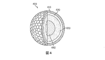
図4は、本開示による態様を有する第4のゴルフボール400を示しており、この第4のゴルフボール400は、フォーピース構造を有する。ゴルフボール400は、第2の内側コア440と、第2の内側コア440を実質的に取り囲む第2の外側コア430と、外側コア430を実質的に取り囲む内側カバー層420と、内側カバー層420を実質的に取り囲む外側カバー層410と、を含む。
FIG. 4 shows a
一般に、本明細書中で使用される「コア」という用語は、ゴルフボールの最も内側にある構造上の要素の少なくとも1つのことを指す。従って、コアという用語は、図3を参照すると(本明細書中で説明されるどの実施例も該当するが)、(1)第1の内側コア330のみ、(2)第1の内側コア330と第1の外側コア320との両方、または、(3)第1の外側コア320のみを指す。また、コアという用語は3層以上を含む場合もあり、例えば、構造上の追加の層が、第1の内側コア330と第1の外側コア320との間に存在しているか或いは第1の外側コア320を取り囲んでいる場合がある。
In general, the term “core” as used herein refers to at least one of the innermost structural elements of a golf ball. Accordingly, the term core is referred to FIG. 3 (which applies to any embodiment described herein): (1) only the first
コアは、ポリウレタン、ポリ尿素、一部または全部が中和されたアイオノマなどの熱硬化性材料または熱可塑性材料、ポリブタジエン、ポリイソプレン、エチレンプロピレンジエン単量体ゴム、エチレンプロピレンゴム、天然ゴム、バラタ、ブチルゴム、ハロブチルゴム、スチレンブタジエンゴムなどの熱硬化性ポリジエンゴム、または種々のスチレンエチレンブタジエンスチレンゴムなどの種々のスチレンブロック共重合体(コポリマ)等、メタロセンまたは他のシングルサイト触媒作用を受けたポリオレフィンやポリウレタンの(例えばシリコンとの)共重合体から形成され得る。 The core is made of polyurethane, polyurea, thermosetting or thermoplastic material such as partially or fully neutralized ionomer, polybutadiene, polyisoprene, ethylene propylene diene monomer rubber, ethylene propylene rubber, natural rubber, balata. Metallocene or other single-site catalyzed polyolefins, such as thermosetting polydiene rubbers such as butyl rubber, halobutyl rubber, styrene butadiene rubber, or various styrene block copolymers (copolymers) such as various styrene ethylene butadiene styrene rubbers Or a copolymer of polyurethane (eg with silicon).
上記の材料に加えて、コア、カバー、または種々の中間層(最内側のコアと最外側のカバー層との間にある層)が1つまたは複数のポリマ(重合体)を組み込み得る。適切な追加のポリマとしては、熱可塑性エラストマ、熱硬化性エラストマ、合成ゴム、熱可塑性加硫物、コポリマ(共重合体)型アイオノマ、ターポリマ(三元重合体)型アイオノマ、ポリカーボネート、ポリオレフィン、ポリアミド、共重合体型ポリアミド、ポリエステル、ポリビニルアルコール、アクリロニトリル−ブタジエン−スチレン共重合体、ポリアリール酸塩、ポリアクリル酸塩、ポリフェニレンエーテル、耐衝撃性改質されたポリフェニレンエーテル、高衝撃性ポリスチレン、ジアリルフタル酸ポリマ、メタロセン触媒作用を受けたポリマ、スチレンアクリロニトリル(SAN)(オレフィン改質されたSANとアクリロニトリル−スチレン−アクリロニトリルを含む)、スチレン−無水マレイン酸(S/MA)ポリマ、スチレン共重合体、機能化スチレン共重合体、機能化スチレン三元重合体、スチレン三元重合体、セルロースポリマ、液晶ポリマ(LCP)、エチレン−プロピレン−ジエン三元重合体(EPDM)、エチレン−酢酸ビニル共重合体(EVA)、エチレン−プロピレン共重合体、エチレン酢酸ビニル、ポリ尿素、およびポリシロキサン、または種々のこれらと同種のメタロセン触媒作用を受けたポリマがあるが、これらに限定されない。また、本発明の範囲を逸脱することなく、組成に追加の材料として使用される適切なポリアミドとしては、以下の(1)〜(4)により得られる樹脂があり、すなわち、(1)シュウ酸、アジピン酸、セバシン酸、テレフタル酸、イソフタル酸または1,4−シクロヘキサンジカルボン酸のような(a)ジカルボン酸と、エチレンジアミン、テトラメチレンジアミン、ペンタメチレンジアミン、ヘキサメチレンジアミンまたはデカメチレンジアミン、1,4−シクロヘキシルジアミンまたはm−キシリレンジアミンなどの(b)ジアミンとの重縮合、(2)ε−カプロラクタムやω−ラウロラクタムなどの環状ラクタムの開環重合、(3)6−アミノカプロン酸、9−アミノノナン酸、11−アミノウンデカン酸または12−アミノドデカン酸などのアミノカルボン酸の重縮合、或いは、(4)ジカルボン酸を有する環状ラクタムとジアミンとの共重合、により得られる樹脂がある。適切なポリアミドの具体例としては、ナイロン6、ナイロン66、ナイロン610、ナイロン11、ナイロン12、共重合体型ナイロン、ナイロンMXD6およびナイロン46がある。
In addition to the above materials, the core, cover, or various intermediate layers (layers between the innermost core and the outermost cover layer) may incorporate one or more polymers (polymers). Suitable additional polymers include thermoplastic elastomers, thermoset elastomers, synthetic rubbers, thermoplastic vulcanizates, copolymer (copolymer) type ionomers, terpolymer (terpolymer) type ionomers, polycarbonates, polyolefins, and polyamides. , Copolymer-type polyamide, polyester, polyvinyl alcohol, acrylonitrile-butadiene-styrene copolymer, polyarylate, polyacrylate, polyphenylene ether, impact-modified polyphenylene ether, high impact polystyrene, diallyl phthalic acid Polymer, metallocene catalyzed polymer, styrene acrylonitrile (SAN) (including olefin modified SAN and acrylonitrile-styrene-acrylonitrile), styrene-maleic anhydride (S / MA) polymer, styrene Copolymer, functionalized styrene copolymer, functionalized styrene terpolymer, styrene terpolymer, cellulose polymer, liquid crystal polymer (LCP), ethylene-propylene-diene terpolymer (EPDM), ethylene- Examples include, but are not limited to, vinyl acetate copolymers (EVA), ethylene-propylene copolymers, ethylene vinyl acetate, polyureas, and polysiloxanes, or various similar metallocene catalyzed polymers. Further, suitable polyamides used as additional materials in the composition without departing from the scope of the present invention include resins obtained by the following (1) to (4): (1) oxalic acid (A) a dicarboxylic acid such as adipic acid, sebacic acid, terephthalic acid, isophthalic acid or 1,4-cyclohexanedicarboxylic acid, ethylenediamine, tetramethylenediamine, pentamethylenediamine, hexamethylenediamine or decamethylenediamine, 1, (B) polycondensation with diamines such as 4-cyclohexyldiamine or m-xylylenediamine, (2) ring-opening polymerization of cyclic lactams such as ε-caprolactam and ω-laurolactam, (3) 6-aminocaproic acid, 9 -Aminononanoic acid, 11-aminoundecanoic acid or 12-aminododecanoic acid There are resins obtained by polycondensation of aminocarboxylic acids such as (4) or copolymerization of cyclic lactams having dicarboxylic acids with diamines. Specific examples of suitable polyamides include
組成に含まれる材料として使用するのに適切な他の材料としては、大韓民国所在のSK Chemicals社がSKYPELという商品名で市販しているポリエステルエラストマ、または日本国倉敷市所在の株式会社クラレがSEPTON(登録商標)という商品名で市販しているジブロックないしトリブロック共重合体、および英国チェスター所在のKraton Polymers Group of Companies社製のKRATON(登録商標)がある。上に挙げた材料はいずれも、本発明の技術的範囲を逸脱することなく用意されるボールの各層に特定の性能を与え得る。 Other materials suitable for use as materials included in the composition include polyester elastomers marketed under the trade name SKYPEL by SK Chemicals in Korea, or Kuraray Co., Ltd. in Kurashiki, Japan. There are diblock or triblock copolymers marketed under the trade name (registered trademark) and KRATON (registered trademark) manufactured by Kraton Polymers Group of Companies in Chester, UK. Any of the materials listed above can provide specific performance to each layer of the ball prepared without departing from the scope of the present invention.
アイオノマもまた、単独で或いは組成物に含まれる成分として、ゴルフボール材料に適している。適切なアイオノマポリマ(すなわち、共重合体または三元重合体の型式のアイオノマ)としては、α−オレフィン/不飽和カルボン酸共重合体ないし三元重合体の型式のアイオノマ樹脂がある。共重合体型アイオノマは、α−オレフィンと、3個〜8個の炭素原子を有するα,β−不飽和カルボン酸とからなる共重合体中のカルボキシル基の少なくとも一部を金属イオンで中和することにより得られる。適切なα−オレフィンの例としては、エチレン、プロピレン、1−ブテンおよび1−ヘキセンがある。適切な不飽和カルボン酸の例としては、アクリル酸、メタクリル酸、エタクリル酸、α−クロロアクリル酸、クロトン酸、マレイン酸、フマル酸およびイタコン酸がある。共重合体型アイオノマとしては、上記の1価または2価の陽イオンによって中和された、多様な酸含有量を有し多様な酸中和度を有するアイオノマがある。 Ionomers are also suitable for golf ball materials, either alone or as a component included in the composition. Suitable ionomer polymers (ie, copolymer or terpolymer type ionomers) include α-olefin / unsaturated carboxylic acid copolymers or terpolymer type ionomer resins. The copolymer-type ionomer neutralizes at least a part of carboxyl groups in a copolymer composed of an α-olefin and an α, β-unsaturated carboxylic acid having 3 to 8 carbon atoms with a metal ion. Can be obtained. Examples of suitable α-olefins are ethylene, propylene, 1-butene and 1-hexene. Examples of suitable unsaturated carboxylic acids are acrylic acid, methacrylic acid, ethacrylic acid, α-chloroacrylic acid, crotonic acid, maleic acid, fumaric acid and itaconic acid. Examples of the copolymer type ionomer include ionomers having various acid contents and various acid neutralization degrees, which are neutralized by the monovalent or divalent cation.
三元重合体型アイオノマは、α−オレフィンと、3個〜8個の炭素原子を有するα,β−不飽和カルボン酸と、2個〜22個の炭素原子を有するα,β−不飽和カルボン酸塩とからなる三元重合体中のカルボキシル基の少なくとも一部を金属イオンで中和することにより得られる。適切なα−オレフィンの例としては、エチレン、プロピレン、1−ブテンおよび1−ヘキセンがある。適切な不飽和カルボン酸の例としては、アクリル酸、メタクリル酸、エタクリル酸、α−クロロアクリル酸、クロトン酸、マレイン酸、フマル酸、およびイタコン酸がある。適切なα,β−不飽和カルボン酸塩としては、アクリル酸メチル、アクリル酸エチル、アクリル酸n−ブチルがある。三元重合体型アイオノマとしては、上記のように1価または2価の陽イオンによって中和された、多様な酸含有量を有し多様な酸中和度を有するアイオノマがある。適切なアイオノマ樹脂の例としては、デラウェア州ウィルミントン所在のE.I.du Pont de Nemours&Company社製のSURLYN(登録商標)という商品名で市販されているものや、テキサス州アービング所在のExxon Mobil Corporation社製のIOTEK(登録商標)という商品名で市販されているものがある。 Ternary polymer type ionomer includes α-olefin, α, β-unsaturated carboxylic acid having 3 to 8 carbon atoms, and α, β-unsaturated carboxylic acid having 2 to 22 carbon atoms. It can be obtained by neutralizing at least part of the carboxyl group in the terpolymer composed of a salt with a metal ion. Examples of suitable α-olefins are ethylene, propylene, 1-butene and 1-hexene. Examples of suitable unsaturated carboxylic acids are acrylic acid, methacrylic acid, ethacrylic acid, α-chloroacrylic acid, crotonic acid, maleic acid, fumaric acid, and itaconic acid. Suitable α, β-unsaturated carboxylates include methyl acrylate, ethyl acrylate, and n-butyl acrylate. As the ternary polymer type ionomer, there are ionomers having various acid contents and various acid neutralization degrees, which are neutralized by monovalent or divalent cations as described above. Examples of suitable ionomer resins include E. coli in Wilmington, Delaware. I. Some are marketed under the trade name SURLYN (registered trademark) manufactured by du Pont de Nemours & Company, and others are marketed under the product name IOTEK (registered trademark) manufactured by Exxon Mobile Corporation of Irving, Texas. .
シリコン材料は、単独で或いは混合材料の成分としてゴルフボールに使用するのにも適している。これらは、追加の強化充填剤を含むか含まない単量体(モノマ)、オリゴマ、プレポリマまたはポリマとすることができる。適切なシリコン材料の1つの種類は、分子内に少なくとも2つの炭素原子を有する少なくとも1つのアルケニル基を組み込むことができる。これらのアルケニル基の例としては、ビニル基、アリル基、ブテニル基、ペンテニル基、ヘキセニル基およびデセニル基があるが、これらに限定されない。アルケニル基は、シリコン構造の一端部または両端部を含む種々の位置に配置され得る。この構成要素に含まれる残部(すなわち、アルケニル基以外)のシリコン結合有機基は、脂肪族不飽和を含有しない炭化水素またはハロゲン化炭化水素基から独立的に選択されるものである。そのような例としては、メチル基、エチル基、プロピル基、ブチル基、ペンチル基、ヘキシル基などのアルキル基、シクロヘキシル基、シクロヘプチル基などのシクロアルキル基、フェニル基、トリル基、キシリル基などのアリル基、ベンジル基、フェネチル基などのアラルキル基、および3,3,3−トリフルオロプロピル基、クロロメチル基などのハロゲン化アルキル基があるが、これらの例に限定されない。本発明において使用するのに適切なシリコン材料の他の種類としては、脂肪族不飽和のない炭化水素基を有するものがある。本発明の組成をつくるのに使用される適切なシリコンの具体例としては、以下のものがあり、すなわち、トリメチルシロキシ閉塞端を有するジメチルシロキサン−メチルヘキセニルシロキサン共重合体、ジメチルヘキセニルシロキシ閉塞端を有するジメチルシロキサン−メチルヘキセニルシロキサン共重合体、トリメチルシロキシ閉塞端を有するジメチルシロキサン−メチルビニルシロキサン共重合体、トリメチルシロキシ閉塞端を有するメチルフェニルシロキサン−ジメチルシロキサン−メチルビニルシロキサン共重合体、ジメチルビニルシロキシ閉塞端を有するジメチルポリシロキサン、ジメチルビニルシロキシ閉塞端を有するジメチルシロキサン−メチルビニルシロキサン共重合体、ジメチルビニルシロキシ閉塞端を有するメチルフェニルポリシロキサン、ジメチルビニルシロキシ閉塞端を有するメチルフェニルシロキサン−ジメチルシロキサン−メチルビニルシロキサン共重合体、および上に挙げた共重合体の少なくとも一端の官能基がジメチルヒドロキシシロキシ基になっている共重合体がある。本発明の範囲を逸脱することなく組成において使用するのに適切な市販のシリコンとしては、ミシガン州ミッドランド所在のDow Corning Corp.社製のSilastic(登録商標)、ニューヨーク州ウォーターフォード所在のGE Silicones社製のBlensil、およびミシガン州エイドリアン所在のWacker Silicones社製のElastosil(登録商標)がある。 Silicon materials are also suitable for use in golf balls, either alone or as a component of mixed materials. These can be monomers (monomers), oligomers, prepolymers or polymers with or without additional reinforcing fillers. One type of suitable silicon material can incorporate at least one alkenyl group having at least two carbon atoms in the molecule. Examples of these alkenyl groups include, but are not limited to, vinyl, allyl, butenyl, pentenyl, hexenyl and decenyl groups. Alkenyl groups can be placed at various positions including one or both ends of the silicon structure. The remaining (ie, other than the alkenyl group) silicon-bonded organic group contained in this component is independently selected from hydrocarbon or halogenated hydrocarbon groups that do not contain aliphatic unsaturation. Examples thereof include alkyl groups such as methyl, ethyl, propyl, butyl, pentyl, and hexyl groups, cycloalkyl groups such as cyclohexyl and cycloheptyl groups, phenyl groups, tolyl groups, and xylyl groups. Although there are aralkyl groups such as allyl group, benzyl group and phenethyl group, and halogenated alkyl groups such as 3,3,3-trifluoropropyl group and chloromethyl group, it is not limited to these examples. Other types of silicon materials suitable for use in the present invention include those having hydrocarbon groups that are free of aliphatic unsaturation. Specific examples of suitable silicon used to make the composition of the present invention include the following: dimethylsiloxane-methylhexenylsiloxane copolymer having a trimethylsiloxy plug end, dimethylhexenylsiloxy plug end Dimethylsiloxane-methylhexenylsiloxane copolymer having dimethylsiloxane-methylvinylsiloxane copolymer having trimethylsiloxy closed end, methylphenylsiloxane-dimethylsiloxane-methylvinylsiloxane copolymer having trimethylsiloxy closed end, dimethylvinylsiloxy Dimethylpolysiloxane having a closed end, dimethylsiloxane-methylvinylsiloxane copolymer having a dimethylvinylsiloxy closed end, methylphenol having a dimethylvinylsiloxy closed end Polysiloxane, methylphenylsiloxane-dimethylsiloxane-methylvinylsiloxane copolymer having a dimethylvinylsiloxy closed end, and a copolymer having a dimethylhydroxysiloxy group as a functional group at least one end of the above-mentioned copolymer There is a coalescence. Commercially available silicon suitable for use in the composition without departing from the scope of the present invention includes Dow Corning Corp., Midland, Michigan. Silastic® manufactured by the company, Blensil manufactured by GE Silicones, Inc., Waterford, NY, and Elastosil® manufactured by Wacker Silicones, Inc., Adrian, Michigan.
本発明の範囲を逸脱することなく他の種類の共重合体もまた組成に加えられ得る。エポキシ基を含有する共重合体であって、本発明の範囲を逸脱することなく使用するのに適切な共重合体の例としては、ポリブタジエンブロックがエポキシ基を含有してなるスチレン−ブタジエン−スチレンブロック共重合体、およびポリイソプレンブロックがエポキシ基を含有してなるスチレン−イソプレン−スチレンブロック共重合体がある。エポキシ基を有するこれらの共重合体の市販品の例としては、日本国大阪所在のダイセル社製のESBS(登録商標) A1005,ESBS A1010,ESBS A1020,ESBS AT018、およびESBS AT019がある。 Other types of copolymers can also be added to the composition without departing from the scope of the invention. Examples of copolymers containing epoxy groups that are suitable for use without departing from the scope of the present invention include styrene-butadiene-styrene wherein the polybutadiene block contains epoxy groups. There are block copolymers and styrene-isoprene-styrene block copolymers in which the polyisoprene block contains an epoxy group. Examples of commercial products of these copolymers having an epoxy group include ESBS (registered trademark) A1005, ESBS A1010, ESBS A1020, ESBS AT018, and ESBS AT019 manufactured by Daicel Corporation, Osaka, Japan.
次に、内側コアと外側コアを有するゴルフボールの製造方法の概要を説明する。ゴルフボール300における第1の内側コア330と第1の外側コア320や、ゴルフボール400における第2の内側コア440と第2の外側コア430などの、マルチピースで形成されたコアを含むゴルフボールが、複数のステップからなるプロセスよって形成され得る。例えば、第1の外側コア320や第2の外側コア430が、第1の内側コア330や第2の内側コア440の周囲に順次型成形される別個の型成形セクションとして最初に形成されるが、一方は第1の内側コア330の周りの外側コア320を形成するものであり、他方は第2の内側コア440の周りの第2の外側コア430を形成するものである。ブタジエンゴム(BR)などの熱硬化性材料からつくられる場合、そのような型成形セクションは、先に型成形されている内側コアを取り囲むことができる半球状セクションつまりコップ形の形状につくられるものであり、これらの半球状セクションが内側コアの周りに型成形されると、これらの半球状セクションが一体に結合して外側コアを形成する。続いて、外側コアと内側コアからなる型成形済み組合せ体は、ゴルフボールを製造するためにさらに加工され得るが、そのような加工としては、例えば、種々の型成形フラッシュを研磨して取り去ること、外側コア/内側コア組合せ体を転動させて外面を粗くすること、さらには、マントルおよび/またはカバー用材料などの追加の材料を施すことがある。
Next, an outline of a method for producing a golf ball having an inner core and an outer core will be described. Golf ball including a multi-piece core such as first
図5Aは、外側コアの半球状セクションをつくるための従来のモールド500の側断面図である。このような半球状セクションは、対応する半球状セクションと整合し得る。これら2つの半球状セクションは、続いて一体に型成形され、例えば、ゴルフボール300の外側コア320や、ゴルフボール400の外側コア430などの、外側コアをつくる。もう1つまたは複数の部品が半球状部分間に配置された後、一体に型成形され得る。モールド500は、材料を圧縮成形するための上側モールドプレート510と下側モールドプレート520を含み得る。下側モールドプレート520が突出部522を含み得る一方で、上側モールドプレート510は突出部522を受ける寸法および形状に形成されたキャビティ512を含み得る。突出部522は、内側コアが配置されるべき半球状セクションの内面に対応する形状を有する。そのような実施例においては、丸みを帯びた突出部として突出部522が設けられる。キャビティ512は、半球状のセクションの外面に対応する形状を有する。下側モールドプレート520は、モールド500が閉じるときに上側モールドプレート510と下側モールドプレート520との間にギャップを生じさせる突起526ないし他のデバイスを含み得る。当業者であれば、代替的に上側モールドプレート510に突起526が配置される場合もあれば、上側モールドプレート510と下側モールドプレート520の両方に突起526が配置される場合もあることを理解されよう。
FIG. 5A is a cross-sectional side view of a
図5Bの例に示されるように、モールド500内において、突出部522とキャビティ512との間にスラグ530が配置され、このスラグ530は、型成形されるべき材料として機能し得る。スラグ530は、外側コア層を型成形するために順次使用される半球状セクションを型成形するのに適切な、上述した熱硬化性材料または種々の他の材料などの材料とすることができる。スラグ530は、ドーム形の形状、円筒形の形状または他の適切な形状などの、モールド500内で使用するのに適切な形状にすることができる。図5Bに示されるように、突出部522に面するスラグ530の面は凹んでいて、突出部522に対応する形状を有している。他の例においては、突出部522に面するスラグ530の面は平らであるか、或いは当技術分野で使用される他の形状を有している。突出部522に面するスラグ530の面は、突出部522上にスラグ530を位置決めし易くする形状に形成され得る。例えば、突出部522に面するスラグ530の面は、図5Bに示されるように、凹んだ形状を有している。
As shown in the example of FIG. 5B, in the
モールド500内にスラグ530の位置を維持し易くするために、突出部522は、該突出部522にスラグ530をある程度くっ付けておくための機械的な固定デバイス524を含み得る。図5Bに示されるように、機械的な固定デバイス524は、例えば、スラグ530の材料に突き通るピンとすることができる。機械的な固定デバイス524の長さは、0.5mm〜5mm或いは0.5mm〜3mmとすることができる。
To facilitate maintaining the position of the
図5Cに示されるように、スラグ530がモールド500内に配置された後、上側モールドプレート510と下側モールドプレート520とが引き合わせられるように、モールド500が閉じられる。上側モールドプレート510と下側モールドプレート520は、案内棒に沿って動く場合もあれば、ヒンジで連結されている場合もあり、あるいは他のデバイス(図示せず)によって駆動される場合には上側モールドプレート510および下側モールドプレート520の少なくとも一方が他方に対して動いてモールド500を閉じることができる。モールド500を閉じるとき、下側モールドプレート520に対して上側モールドプレート510を約85kg/cm2〜約170kg/cm2の範囲の圧力で押し込むと、スラグ530は、上側モールドプレート510と下側モールドプレート520との間にあるギャップ内で外側へある程度まで膨らみ得るが、上側モールドプレート510と下側モールドプレート520との間において、とりわけ、突出部522の外面上かつキャビティ512内において、変形される。一実施例においては、スラグ530の硬化を支援するために、上側モールドプレート510および下側モールドプレート520の少なくとも一方が加熱され得る。
As shown in FIG. 5C, after the
一実施例においては、モールドが、1つまたは複数の位置合せピンと、これらの位置合せピンに対応する1つまたは複数の穴と、を含む。位置合せピンは、型成形プロセス中にモールドプレートの位置合せを支援することができる。そのような位置合せピンは、突起526の代わりにモールド内に設けられ得る。図14Aを見ると、外側コアの半球状セクションをつくるためのモールド1000の一例が示されている。モールド1000は、材料を圧縮成形するための上側モールドプレート1010および下側モールドプレート1020を含み得る。下側モールドプレート1020が突出部1022を含み得る一方で、上側モールドプレート1010は、突出部1022を受ける寸法および形状に形成されたキャビティ1012を含み得る。下側モールドプレート1020は、上側モールドプレート1010と下側モールドプレート1020との間の位置合せを支援するように上側モールドプレート1010と噛合する1つまたは複数の位置合せピン1026または他のデバイスを含み得る。例えば、上側モールドプレート1010は、下側モールドプレート1020の1つまたは複数の位置合せピン1026に対応する1つまたは複数の位置合せ穴1029を含む。このような位置合せピン1026および位置合せ穴1029は、モールド1000が閉じるときに突出部1022とキャビティ1012とを同心つまり同軸とする位置合せを支援することができる。当業者であれば、代替的に上側モールドプレート1010に位置合せピン1026が配置されるとともに、下側モールドプレート1020に位置合せ穴1029が設けられる場合もあれば、上側モールドプレート1010と下側モールドプレート1020の両方に位置合せピン1026と位置合せ穴1029が設けられる場合もあることが理解されよう。
In one example, the mold includes one or more alignment pins and one or more holes corresponding to the alignment pins. The alignment pins can assist in alignment of the mold plate during the molding process. Such an alignment pin can be provided in the mold instead of the
図14Bの例に示されるように、モールド1000内において突出部1022とキャビティ1012との間に、型成形されるべき材料として機能し得るスラグ1030が配置されている。図5Cのモールド500に関して上述したのと同様に、モールド1000内にスラグ1030が配置された後、モールド1000が閉じられ、図14Cに示されるように、上側モールドプレート1010と下側モールドプレート1020とが合わせられる。
As shown in the example of FIG. 14B, a
図5Cにおけるモールド500の突出部522とキャビティ512との各面の形状により、スラグ530は、半球状セクション632などの特定の形状に変形される。同様に、図14Cにおけるモールド1000のキャビティ1012と突出部1022の形状が、半球状セクション632などの特定の形状にスラグ1030を変形させることができる。このような半球状セクション632は、コップ形の形状を有し得る。半球状セクション632は、例えば、第1の外側コア320や第2の外側コア430(これらは2つの半球状セクション632から順次型成形される)などの、外側コアの実質的に半部を形成し得る。
The
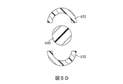
第2の半球状セクション632が型成形されると、この半球状セクション632は、図5Dに示されるように、先に型成型済みの内側コア640を取り囲むように配置される。そして、半球状セクション632間に内側コア640が配置されるとともに、図5Eに示されるように、上側モールド710と下側モールド712との間に、半球状セクション632および内側コア640が配置される。続いて上側モールド710と下側モールド712とが一緒に押圧されて半球状セクション632を結合させると、完全なコアが形成され、この完全なコアは、内側コア640を取り囲む外側コアを有する。そのような外側コアとしては、図3に示されるゴルフボール300の外側コア320や、図4に示されるゴルフボール400の外側コア430がある。
Once the second
図5A〜図5Cに示されているプロセスに型成形用半球状セクション632があるときに特に気を付けるべきことは、型成形プロセス中にスラグ530がモールド500内の中心に正しく配置されているようにすることである。型成形プロセス中にモールド500内にスラグ530が正しく配置されていなければ、半球状セクション632は、不出来な形状につくられてしまう。
It should be particularly noted when the molding
例えば、突出部522の上部に配置されたスラグ530は、型成形が完了する前に、突出部522およびキャビティ512に対して動いてしまうことがある。図6Aに示されるように、スラグ530は、突出部522の上側部分527から滑り落ちることなどにより、方向10へ動いてしまうことがある。この動きが生じると、上側モールドプレート510と下側モールドプレート520との間にスラグ530が押圧された後、このスラグ530は、突出部522の第1の側523に位置する部分の方が突出部522の第2の側525に位置する部分よりも大きくなり得るので、半球状セクション(図示せず)の構造が望ましくない形状になってしまう恐れがある。その結果、型成形済み半球状セクション632は、一方の側が他方の側よりも厚くなり、ひいては、内側コアがゴルフボール内で中心からずれた位置になってしまう。例えば、図6Bに示されるように、型成形プロセス後に、内側コア640が外側コア650内で偏った位置にある。例えば、内側コア640の中心642が、外側コア650の中心652からずれた位置になる。中心652は、内側コア640と外側コア650を含むゴルフボールの中心でもあり得る。このような中心のずれた内側コアがあると、ゴルフボールの最善の完成品を得ることはできない。例えば、USGA対称試験の飛び(飛翔)の成績は、不満足なものとなろう。
For example, the
本明細書中で説明する実施例は、型成形プロセス中に型成形材料が正しい位置から動いてしまうことを抑え或いは回避させる機械および方法を提供することによってこの問題に有利に対処する。この問題に対処する方法の一つとしては、突出部522の上側部分527と下側モールドプレート520の面529との間の距離を縮めることがある。
The embodiments described herein advantageously address this problem by providing a machine and method that prevents or avoids the molding material from moving from the correct position during the molding process. One way to deal with this problem is to reduce the distance between the
図7には、半球状セクションを型成形するための型成形用プレート620の一実施例が示されている。型成形用プレート620は、上側面623と、この上側面623から突出している複数の突出部622と、を有する。突出部622と上側面623とは互いに対して動くように構成されている。図8には、型成形用プレート620の1つの突出部622が、1つまたは複数のキャビティ612を有する上側モールドプレート610とともに断面図で示されている。キャビティ612と突出部622とからなる各対が、完全なモールドキャビティを形成し得る。型成形プロセス中に上側モールドプレート610とモールドプレート620とが一体になるときに突出部622がキャビティ612内に挿入されるように、上側モールドプレート610のキャビティ612が突出部622に対応している。
FIG. 7 shows one embodiment of a
モールドプレート620は可動インサート628を含む。可動インサート628は、突出部622が突き出るように通る孔627を有する平らなプレートの形態であるとよい。その結果、突出部622が可動インサート628の孔から突き出るときに、可動インサート628は、一平面内で突出部622を取り囲む。図8に示されるように、上側モールドプレート610と可動インサート628とが接触しないように、かつ可動インサート628が突出部622の上面625に近接して配置され得るように、上側モールドプレート610とモールドプレート620とが離間して設けられている。他の例においては、突出部622は、所定の大きさだけ可動インサート628よりも高く突き出る。例えば、突出部622の上面625は、約0.5mm〜約7mmだけ可動インサート628よりも高く突き出る。他の例においては、突出部622の上面625は、約1mm〜約5mmだけ可動インサート628よりも高く突き出る。他の例においては、突出部622の上面625は、約1mm〜約3mmだけ可動インサート628よりも高く突き出る。突出部622の上面625が7mmよりも高く可動インサート628から突き出ることは、スラグが突出部522から滑り落ちて中心のずれたコアがつくられる恐れがあるので、好ましくはない。
可動インサート628は、1つまたは複数の付勢デバイス629を介してモールドプレート620に結合され得る。付勢デバイス629は、例えば、モールドプレート620の下側面612から可動インサート628を離して上側モールドプレート610へ向けて付勢するバネとすることができる。らせんバネ、コイルバネ、圧縮バネ、および当技術分野で周知の他の型式のバネを使用することができる。可動インサート628を付勢するのに使用されるバネのバネ定数は、可動インサート628の重量を考慮して決めるとよい。一例においては、可動インサート628の重量が約71kgであるときに、7.2kg重/mmのバネ定数を有する4つのバネ(外径40mm)と、2.2kg重/mmのバネ定数を有する4つのバネ(外径30mm)を使用することができる。バネの材料は、限定されるものではなく、本開示で説明される実施例に即して使用するのに適切な材料であればよい。一実施例においては、バネの材料は、弁バネ用シリコン・クロム鋼オイルテンパー線(SWOSC−V)である。付勢デバイス629がバネである場合、突起626は、可動インサート628に付勢デバイス629を取り付けることを支援するバネ用アンカとして機能する。これに関して、突起626のこのアンカ機能は、上側モールドプレート510と下側モールドプレート520との間の離間機能に追加される機能である場合もあれば、離間機能の替りの機能である場合もある。
The
他の例においては、付勢デバイス629は、駆動源付き接続とすることができる。例えば、付勢デバイス629は、モールドプレート620に対して可動インサート628を動かすモータから動力を与えられる。他の例においては、付勢デバイス629は、空圧式手段、油圧式手段、または当技術分野において周知の他の手段から動力を与えられる。可動インサート628はまた、上側モールドプレート610とモールドプレート620とが互いに接近したときに、これらのプレートの間にギャップをもたらす1つまたは複数の突起626または他のデバイスを含み得る。ところで、突起626は、代替的に上側モールドプレート610に設けられる場合もあれば、上側モールドプレート610とモールドプレート620の両方に設けられる場合もある。
In other examples, the
図9に示されるように、上側モールドプレート610とモールドプレート620との間にスラグ630が挿入され得る。特には、スラグ630は、突出部622の上側面625上に配置される。図9に示されるように、可動インサート628に面しているスラグ630の下側面は、上側モールドプレート610に面する可動インサート628の上側面に接触し得る。このように配置することにより、突出部622からスラグ630が滑り落ちてしまうことを有利に抑え或いは回避させることができる。さらには、突出部622は、上述したように、スラグ630の位置を維持することや位置決めすることを支援する機械的な固定デバイス624を含み得る。
As shown in FIG. 9, a
上側モールドプレート610とモールドプレート620とが互いに離れているときに、可動インサート628は突出部622の上面625に近接しているので、この可動インサート628はスラグ630にも近接して配置され得る。例えば、スラグ630が既に可動インサート628に接触している場合もあれば、可動インサート628と接触する方向へ動く場合もあり、これによって、スラグ630を実質的に支持し或いはスラグ630の意図しない動きを実質的に止める。その結果、可動インサート628は、型成形プロセス中にスラグ630が相当な程度動くことを許さないので、型成形プロセス中にスラグが動いてしまうことで不出来な半球状セクションがつくられてしまう問題に有利に対処する。
When the
可動インサート628が完全に伸びきっているが上側モールドプレート610と突起626とが接触していないとき、可動インサート628は、可動インサート628とスラグ630との間にギャップ20をもたらすように第1の位置(第1の上側位置など)に位置し得る。ギャップ20の寸法は、半球状セクションの型成形される形状に実質的に悪影響を与えない程度だけスラグ630が動き得る寸法かつ半球状セクション内の中心に最終的に内側コアが配置されることにも悪影響を与えない寸法にされ、スラグ630が可動インサート628と接触して動きを止める。他の例においては、可動インサート628は、第1の上側位置よりも低い第2の上側位置などの第2の位置に位置し得るが、この第2の位置において、可動インサート628はスラグ630と接触している。このような第2の例においては、スラグ630は、突出部622に対して横方向および/または回転方向に実質的に動かない。
When the
作業員などによって上側モールドプレート610とモールドプレート620との間にスラグ630が配置された後、上側モールドプレート610とモールドプレート620とが引き合わせられると、モールドスラグ630を圧縮成形して半球状セクションにするプロセスが始まる。型成形プロセス中に、モールドプレート620と可動インサート628とは互いに対して動き得る。例えば、図10に示されるように、上側モールドプレート610とモールドプレート620とが接近したときに、上側モールドプレート610は、可動インサート628を押圧するように接触し(互いに直接に或いは突起626を挟んで)、これによって、モールドプレート620の下側面621へ向かう方向640へ可動インサート628が押し下げられる。このような例においては、モールドプレート620の下側面621が第1の面として機能するとともに、可動インサート628によって形成された面623が第2の面として機能し、型成形プロセス中に、第1の面と第2の面とが互いに対して動いている。上側モールドプレート610が可動インサート628に直接接触する場合(突起626が存在しないときなど)、上側モールドプレート610と可動インサート628との間にギャップが形成され、このギャップ内でスラグ630が変形して半球状セクションに型成形され得る。このときの動きに起因して、可動インサート628がモールドプレート620内へ引っ込められるか或いは突出部622に対して動き得る。モールドプレート620に対する可動インサート628のこの動きは、付勢デバイス629がバネなどのエネルギ保存型デバイスである場合には、付勢デバイス629の抵抗に打ち勝ち得るが、或いは、付勢デバイス629が空圧式、油圧式またはモータ駆動式ピストンなどの駆動源付き作動デバイスである場合、付勢デバイス629は、可動インサート628の下降する動きに従って下方へ駆動され得る。
After the
図11を見ると、スラグ630を圧縮成形して半球状セクションにすることを完了するのに必要な所定の圧力を受けて、上側モールドプレート610とモールドプレート620とが完全に接近している。加えられる圧力は、例えば、約85kg/cm2〜約170kg/cm2の範囲の大きさの圧力とすることができる。この位置においては、スラグ630が突出部622の周りで型成形されるように、可動インサート628がモールドプレート620内の内部空間内へ押し込まれている。可動インサート628がモールドプレート620の内部空間内へ押し込まれると、可動インサート628はモールドプレート620と接触するようになり得る。結果として得られる半球状セクションは、内側コアを受けるように構成された突出部622の概形の凹部631を有する。換言すれば、可動インサート628は初期には、スラグ630の動きを抑えて型成形される半球状セクションが不出来にならないようにする位置にあるが、この初期位置は、半球状セクションをコップ形の形状にし、凹部631を形成することを導くものではない。従って、型成形中に上側モールドプレート610とモールドプレート620とが引き合わせられるときに、可動プレート628がモールドプレート620内の内部空間内へ駆動される。可動インサート628のこの動きによって、スラグ630が型成形されて内側コアを受けるのに適した凹部631を有する半球状セクションになり得るように、スラグ630が突出部622の周囲で変形されることが可能となる。
Referring to FIG. 11, the
型成形プロセスが完了して、スラグ630が図5Dに示される半球状セクション632などの半球状セクションに型成形されると、第2の半球状セクションが型成形され、これら2つの半球状セクションが一体に結合されることで、図5Eに示されているような、内側コアの周りに外側コアを有する完全なコアを形成する。結果として得られるコア組合せ体は、その後、ゴルフボールを生産するための上述した様式で加工され得る。
When the molding process is complete and the
他の構成や他の例が上述した実施例に採用され得る。例えば、図7に示される突出部622のすべてに対して同時に可動インサート628が動くように、可動インサート628は、突出部622のすべてを取り囲む単一のプレートとして用意される。他の例においては、モールドプレート620は突出部622の複数のグループに応じる複数の可動インサート628を含み、所定のグループ内の突出部622が1つの可動インサート628によって取り囲まれる。他の例においては、各突出部622に個別に可動インサート628が設けられ、この可動インサート628は、他の可動インサート622に対して互いに独立して動く。
Other configurations and other examples may be employed in the embodiments described above. For example, the
図7に示されるように、モールドプレート620は、複数の突出部622を含み得る。他の例によれば、型成形プレート620に、単一の突出部622と、この突出部622を取り囲む単一の可動インサート628と、が設けられる。
As shown in FIG. 7, the
他の構成によれば、モールドは、半球状セクションの互いに対応するセットを製造し得る。図12に示されるように、モールド800は、キャビティ812を有する上側モールドプレート810と、キャビティ832を有する下側モールドプレート830と、中間プレート820とを含み得る。中間プレート820は、第1の突出部822と第2の突出部823とを含み、これらの突出部はそれぞれ、第1の可動インサート828と第2の可動インサート827によって取り囲まれ得るものであり、第1の可動インサート828を通って第1の突出部822が突き出る一方で、第2の可動インサート827を通って第2の突出部823が突き出る。上述したように、可動インサート828,827は、付勢デバイス829を介して中間プレート820に接続され得る。そして、キャビティ812に対向する第1の突出部822上にスラグ(図12に示さず)が配置され、キャビティ832内にスラグが配置され得る。このスラグは、図9におけるスラグ630と同様に、可動インサート828と接触し得る。型成形プロセス中に、上側モールドプレート810は、該上側モールドプレート810に対向する第1の可動インサート828と接触するまで方向840へ動くように作動され、これによって、中間プレート820に対して第1の可動インサート828が動き得るが、このとき、第1の突出部822とキャビティ812との間にもたらされた空間内でスラグが型成形される。逆も言えて、下側モールドプレート830は、該下側モールドプレート830に対向する第2の可動インサート827と接触するまで方向842へ動き、これによって、第2の可動インサート827が上昇し得るが、このとき、第2の突出部823とキャビティ832との間にもたらされた空間内でスラグが型成形される。モールド800によってつくられた半球状セクションは、続いてモールド内の内側コアの周りに配置され、図5Eに示される例を参照して説明したように、外側コア/内側コア組合せ体を形成する。
According to other configurations, the mold may produce a corresponding set of hemispherical sections. As shown in FIG. 12, the mold 800 may include an
他の例においては、半球状セクションがつくられた後、型成型済み半球セクションは、それぞれ、キャビティ812とキャビティ832内に維持される。モールド800から中間プレート820が取り外されるとともに、キャビティ812内の半球状セクションおよびキャビティ832内の半球状セクションのうちの少なくとも一方の内部に内側コア(図示せず)が配置されて、外側コア/内側コア組合せ体を形成する。このようなプロセスは、Chien−Hsin Chouらの名義で2011年12月5日に出願された米国特許出願公開第_______号(現在のところ米国特許出願第13/311,415号)明細書(発明の名称「Method For Compression Molding A Dual Core For A Golf Ball」)に説明されており、この出願の全体が本願の参照となる。
In other examples, after the hemispherical section is created, the molded hemispherical sections are maintained in
圧縮成形プロセス中に、スラグの材料などの型成形される材料は、モールドの表面や側壁に蓄積する恐れがある。さらには、モールドは、精度が比較的厳しく面間ギャップが比較的小さいとしても、型成形される材料もまた、その面間の小さなギャップ内へ押圧される恐れがある。このように型成形材料が望ましくない位置に蓄積すると、型成形プロセスの精度に悪影響を与え、モールド構成要素の動きを妨害し或いは動かなくしてしまうことさえある。 During the compression molding process, the material to be molded, such as slag material, can accumulate on the mold surface and sidewalls. Furthermore, even though the mold is relatively precise and the gap between the faces is relatively small, the material to be molded can also be pressed into the small gap between the faces. This accumulation of molding material in undesirable locations can adversely affect the accuracy of the molding process and can interfere with or even prevent movement of the mold components.
一実施例によれば、型成形済み半球状セクションを突出部から取り外し易くするコーティングを、モールドプレートの突出部が含み得る。図13の例に示されるように、モールドプレート910は、上述したように、突出部と、1つまたは複数の付勢デバイス929を介してモールドプレート920に接続された可動インサート928と、を含み得る。型成形済み半球状セクションを突出部922から取り外し易くするために、テフロン(登録商標)、EFTEまたは青いフルオロポリマフィルムなどの剥離剤コーティング950が、突出部922、および/または可動インサート928、および/またはモールドプレート920の壁に施され得る。また、コーティング950が施されていれば、スラグからの材料などの型成形材料が蓄積してしまうことを抑えることができるが、そうでなければ、突出部922と可動インサート928との間の空間に蓄積してしまい、ひいては、スラグからの材料が硬化して、可動インサート928が動かなくなる恐れがある。コーティング950は、摩擦係数の小さな材料からつくられているとよい。突出部922はまた、上述したように、コーティング950を通って上に突き出る機械的な固定デバイス924を含む場合があり、そのような機械的な接続デバイス924は、少なくとも一部がコーティング950によってコーティングされていない。機械的な固定デバイス924は、コーティング950によって完全にコーティングされている場合もある。一実施例においては、機械的な固定デバイス924がコーティング950を通って上に突き出るので、そのような機械的な固定デバイス924は、少なくとも一部がコーティング950によってコーティングされていない。
According to one embodiment, the protrusion of the mold plate may include a coating that facilitates removal of the molded hemispherical section from the protrusion. As shown in the example of FIG. 13, mold plate 910 includes a protrusion and a
図15には、半球状セクションを型成形するための型成形用プレートの一実施例が示されている。図15に示されるように、型成形用プレートは、該下側モールドプレート1120の上面1123を通って突き出る1つまたは複数の突出部1122を含む下側モールドプレート1120として用意され得る。
FIG. 15 shows one embodiment of a molding plate for molding a hemispherical section. As shown in FIG. 15, the mold plate may be provided as a
図16には、型成形用プレート1120の突出部1122の1つが、この突出部1122に対応する1つまたは複数のキャビティ1112を有する上側モールドプレート1110とともに断面で示されている。キャビティ1112と突出部1122からなる各対が、完全なモールドキャビティを形成し得る。下側モールドプレート1120は、可動プレート1128を含み得る。可動プレート1128は、下側モールドプレート1120の上面1123を形成し得る。可動プレート1128は、突出部1122が突き出るように通る孔1127を含む平らなプレートの形態であるとよい。その結果、突出部1122が可動プレート1128の孔を通って突き出るときに、可動プレート1128は、突出部1122を一平面内などで取り囲み得る。さらには、図16および図17に示されるように、可動プレート1128は、下側モールドプレート1120のエッジまで行き着くプレートとして設けられ得るものであって、図7および図8の例に示されるように下側モールドプレート1120の凹部内にフィットするインサートとして提供されるものではない。
In FIG. 16, one of the
図16に示されるように、上側モールドプレート1110と可動プレート1128とが接触しないように、上側モールドプレート1110と下側モールドプレート1120とが分離されている場合、可動プレート1128は、突出部1122の上面1125に近接して配置され得る。他の例においては、突出部1122は、所定の大きさだけ可動プレート1128よりも上に突き出る(例えば、上面1123よりも上に突き出る)。例えば、突出部1122の上面1125は、約0.5mm〜約7mmだけ可動プレート1128よりも上に突き出る。他の例においては、突出部1122の上面1125は、約1mm〜約5mmだけ可動プレート1128よりも上に突き出る。他の例においては、突出部1122の上面1125は、約1mm〜約3mmだけ可動プレート1128よりも高く突き出る。いくつかの実施例においては、突出部1122からスラグが滑り落ちて、中心のずれたコアをつくってしまわないように、突出部1122の上面1125よりも最大で7mmまで上に突き出ることが望ましい。
As shown in FIG. 16, when the
可動プレート1128は、1つまたは複数の付勢デバイス1129を介して下側モールドプレート1120に結合されるとよい。上述したように、付勢デバイス1129は、例えば、可動プレート1128を、下側モールドプレート1120の下側面1121から遠ざけて上側モールドプレート1110の方向へ付勢するバネである。他の例においては、上述したように、付勢デバイス1129が駆動源付き接続であり得る。例えば、付勢デバイス1129は、空圧式、水圧式またはモータ駆動式ピストンなどの駆動源付きデバイスである。
The
一実施例においては、上側モールドプレート1110および下側モールドプレート1120は、位置合せピンと、この位置合せピンに対応する1つまたは複数の穴と、を含む。これらの位置合せピンは、型成形プロセス中にモールドプレートを位置合せすることを支援することができる。例えば、上側モールドプレート1110は、上側モールドプレート1110と下側モールドプレート1120との間の位置合せを支援するように、下側モールドプレート1120と噛合する1つまたは複数の位置合せピン1126または他のデバイスを含む。例えば、可動プレート1128は、上側モールドプレート1110の1つまたは複数の位置合せピン1126に対応する1つまたは複数の位置合せ穴1133を含む。そのような位置合せピン1126と位置合せ穴1133は、モールドが閉じるときに突出部1122とキャビティ1112とを同心つまり同軸とする位置合せを支援することができる。当業者であれば、代替的に可動プレート1128に位置合せピン1126が設けられるとともに上側モールドプレート1110に位置合せ穴1133が設けられる場合もあれば、上側モールドプレート1110と下側モールドプレート1120の両方に位置合せピン1126と位置合せ穴1133が設けられる場合もあることを理解されよう。他の例においては、可動プレート1128に位置合せピン1126が設けられ、この位置合せピン1126は、可動プレート1128に付勢デバイス1129を取り付けることを支援する付勢デバイス1129用アンカとして機能する。
In one embodiment,
図17の例に示されるように、上側モールドプレート1110と下側モールドプレート1120との間にスラグ1130が挿入され得る。特には、突出部1122の上面1125にスラグ1130が設けられる。可動プレート1128に面しているスラグ1130の下側面が、上側モールドプレート1110に面する可動プレート1128の上面1123に接触し得る。例えば、図17に示されるように、スラグ1130の側方部1131が可動プレート1128に接触する。このように配置することにより、突出部1122からスラグ1130が滑り落ちることを有利に抑えるか或いは回避させることができる。突出部1122は、上述したように、スラグ1130の位置を維持することや位置決めすることを支援する機械的な固定デバイス1124を含み得る。
As shown in the example of FIG. 17, a
作業員などによって上側モールドプレート1110と下側モールドプレート1120との間にスラグ1130が配置された後、上側モールドプレート1110と下側モールドプレート1120とが合わせられると、スラグ1130を型成形して半球状セクションにするための圧縮成形プロセスが始まる。型成形プロセス中に、下側モールドプレート1120と可動プレート1128とは互いに対して動き得る。例えば、図18に示されるように、上側モールドプレート1110と下側モールドプレート1120が接近すると、上側モールドプレート1110が可動プレート1128に接触して押圧し、これによって、可動プレート1128は、下側モールドプレート1120の下側面1121の方向1140へ押し下げられる。上側モールドプレート1110と可動プレート1128とが接触するとき、位置合せピン1126が、位置合せ穴1133に挿入される。このような例においては、下側モールドプレート1120の下側面1121が第1の面として機能し、可動プレート1128によって形成される面1123が第2の面として機能し得るが、これらの第1の面と第2の面は、型成形プロセス中に互いに対して動いている。下側モールドプレート1120に対する可動プレート1128のこの動きは、付勢デバイス1129がバネなどのエネルギ保存型デバイスである場合には付勢デバイス1129の抵抗に打ち勝ち得る。或いは、付勢デバイス1129は、可動プレート1128の下降する動きに従って下方へ駆動され得る。
After the
図19には、スラグ1130を圧縮成形して半球状セクションにすることを完了させることができる所定の圧力を受けて、上側モールドプレート1110と下側モールドプレート1120とが完全に接近している。加えられる圧力は、例えば、約85kg/cm2〜約170kg/cm2の範囲の大きさの圧力とすることができる。図19に示されるように、この位置において、可動プレート1128は下側モールドプレート1120に押しつけられている。可動プレート1128のこの動きによって、内側コアを受けるのに適切な凹部を有する半球状セクションにスラグ1130が型成形され得るように、スラグ1130が突出部1122の周りで変形することが可能となる。
In FIG. 19, the
型成形プロセスが完了して、図5Dに示されている半球状セクション632のような半球状セクションにスラグ1130が型成形された後、第2の半球状セクションが型成形されて、これら2つの半球状セクションが一体に結合されると、図5Eに示されているような内側コアの周りに外側コアを有してなる完全なコアを形成する。結果として得られるコア組合せ体は、その後、ゴルフボールを生産するための上述した様式で加工され得る。
After the molding process is complete and the
図20には、モールドの一実施例として、第1のキャビティ1212を有する上側モールドプレート120と、第2のキャビティ1232を有する下側モールドプレート1230と、可動プレート1228を有する中間プレート1220と、を含むモールドが示されており、可動プレート1228は、1つまたは複数の付勢デバイス1229を介して中間プレート1220に接続している。上側モールドプレート1210は、1つまたは複数の位置合せピン1226を含み得る。可動プレート1228は、1つまたは複数の位置合せ穴1227を含み、中間プレート1220は、1つまたは複数の位置合せ穴1225を含み、下側モールドプレート1230は、モールドが閉じられるときに位置合せピン1226を受ける1つまたは複数の位置合せ穴1233を有し得る。ところで、代替的に下側モールドプレート1230などのモールドの他の構成要素に位置合せピン1226が配置される場合もある。
In FIG. 20, as an example of the mold, an
中間プレート1220は、第1の突出部1222と第2の突出部1223を含み得る。第1の突出部1222は、第1の高さ1244を有し、第2の突出部1223は、第2の高さ1246を有し得る。第1の突出部1222の第1の高さ1244は、第2の突出部1223の第2の高さ1246よりも高くされ得る。例えば、第1の突出部1222は可動プレート1228を通って可動プレート1228の厚さを過ぎて突き出るので、第1の高さ1244は第2の高さ1246よりも高くされ得る。
The
一実施例によれば、第1の突出部1222の第1の高さ1244は、可動プレート1228の厚さだけ第2の突出部1223の第2の高さ1246よりも高い。図20に示されるように、上側モールドプレート1210を方向1240に動かし、下側モールドプレート1230を方向1242に動かすことなどにより、モールドが閉じられると、上側モールドプレート1210が可動プレート1228に接触してこの可動プレート1228を中間プレート1220へ向けて押し下げ、ついには、可動プレート1228は中間プレート1220に接触する。モールドが閉じられるとき、下側モールドプレート1230は中間プレート1220に接触し得る。しかし、下側モールドプレート1230は中間プレート1220に直接接触し得るが、上側モールドプレート1210は、可動プレート1228の厚さだけ中間プレート1220から離間され得る。ほぼ同じ寸法と形状を有する第1のキャビティ1212と第2のキャビティ1232の中で半球状セクションを生産することが望まれる場合、第1の突出部1222の第1の高さ1244が可動プレート1228の厚さだけ第2の突出部1223の第2の高さ1246よりも高いことが望ましい。第1の高さ1244が可動プレート1228の厚さだけ第2の高さ1246よりも高く構成されていることにより、ほぼ同じ半球状セクションを提供することができ、ひいては、デュアルコアを形成すること、さらには所望の性能と質を有するデュアルコアのあるゴルフボールを形成することを支援することができる。
According to one embodiment, the
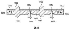
図21には、可動プレート1300の上面が示されている。可動プレート1300は、図20の可動プレート1228と同様に使用され得る。可動プレート1300は、1つまたは複数の第1の突出部1320が突き出るように通る1つまたは複数の孔1320を含み得る。可動プレート1300はまた、モールドプレートの位置合せピン(図示せず)を受ける1つまたは複数の位置合せ穴1324を含み得る。図22は、図21における22−22線に沿って切り出された側断面図であり、可動プレート1300は、1つまたは複数の第1の突出部1322とともに1つまたは複数の第2の突出部1323を含む中間プレート1330の一部である。可動プレート1300は、1つまたは複数の付勢デバイス1329を介して中間プレート1330に接続されていて、この付勢デバイス1329は、可動プレート1300を、中間プレート1330から遠ざける方向に上向きに付勢する。可動プレート1300は、1つまたは複数のピン1328を介して中間プレート1330にさらに接続され得る。図22に示されるように、ピン1328は、中間プレート1330内に設けられた凹部1332にフィットするように、1つまたは複数の横方向に延在する拡大ヘッドを有し得る。例えば、ピン1328は、図22に示されるように、ほぼ「T」字形の形状に形成されたヘッドを有する。
FIG. 21 shows the upper surface of the
従って、付勢デバイス1329が可動プレート1300を中間プレート1330から遠ざける方向へ上昇させようとしているときに、ピン1328のヘッドが凹部1332の面と係合することで、付勢デバイス1329が可動プレート1300を中間プレート1330から遠ざけるように上昇させるときの距離を制限するように制御する。そして、ピン1328は、可動プレート1300の上面と、突出部1322の上面との間の距離を制御するように使用され得るとともに、突出部1322の上面に置かれたスラグ(図示せず)の安定性に影響を与える。ピン1328は、例えば、ネジ、ボルト若しくは当技術分野で使用される他の固定具などの固定具1326を介して可動プレート1300に接続され得る。他の例においては、ピン1328は、可動プレート1300と一体の単一部品の構成として形成され得る。
Therefore, when the
中間プレート1330を含むモールドが閉じられるときに、モールドプレートは可動プレート1300に接触するようになり、可動プレート1300を中間プレート1330の方向へ押し進める。図23に示されるように、可動プレート1300は中間プレート1330と接触するように強制され得る。このことが生じるときに、ピン1328もまた下方へ強制されて凹部1332から抜け出る。型成形プロセスが完了した後、モールドが開かれると、可動プレート1300にかかっていた圧力が開放され、付勢デバイス1329が可動プレート1300を中間プレート1330から遠ざける方向に動かして、図22に示される位置まで動かすことが可能となる。
When the mold including the
実施例Example
ゴルフコアは以下に説明するように加工された。内側コアは、HPF2000とHPFAD1035の混合物(HPFとHPF AD1035は、E.I.DuPont de Nemours and Co.社製のアイオノマ樹脂の商品名である)からつくられ、外側コアはTAIPOL(登録商標)BR150からなるゴム化合物(TAIPOL BR150は、Taiwan Synthetic Rubber Corporation社製のゴムの商品名である)からつくられた。内側コアは、射出成形によりつくられた(圧縮成形でつくることもできるが)。射出成型機の温度は、190℃〜220℃の範囲に設定された。外側コアは圧縮成形によりつくられ、そのときの圧縮成形機の温度は、130℃〜170℃の範囲に設定された。 The golf core was processed as described below. The inner core is made from a mixture of HPF2000 and HPFAD1035 (HPF and HPF AD1035 are trade names for ionomer resins from EI DuPont de Nemours and Co.) and the outer core is TAIPOL® BR150. (TAIPOL BR150 is a trade name of rubber manufactured by Taiwan Synthetic Rubber Corporation). The inner core was made by injection molding (although it could be made by compression molding). The temperature of the injection molding machine was set in the range of 190 ° C to 220 ° C. The outer core was made by compression molding, and the temperature of the compression molding machine at that time was set in the range of 130 ° C to 170 ° C.
外側コア/内側コア組合せ体の100ピースが、可動プレートを有する中間プレートを含む圧縮モールドを使ってつくられた(「実施例」)。外側コア/内側コアの組合せの100ピースが、可動プレートを有する中間プレートを含まない圧縮モールドを使ってつくられた(比較例)。コアの完成後、少なくとも4時間冷却されて、すべてのコアがカッターで半分に切られた。外側コア内での内側コアの中心のずれが0.8mm以下であった場合、OKとマークされた。外側コア内での内側コアの中心のずれが0.8mmよりも大きかった場合、NGとマークされた。結果は以下のようになった。

かくして、可動プレート(つまり可動インサート)を有する中間プレートを使用することにより、型成形済みのコアが中心からずれてしまう割合を、満足できる程度まで有利に減らすことができる。 Thus, by using an intermediate plate with a movable plate (ie, a movable insert), the rate at which the molded core is displaced from the center can be advantageously reduced to a satisfactory degree.
本発明の様々な実施例について説明したが、上記の説明は例示することを意図しており、限定することを意図していない。本発明の範囲を逸脱することなく、さらに多くの実施形態および応用例が可能であることが当業者に明らかであろう。従って、本発明は、添付の特許請求の範囲およびこれの均等物に照らすこと以外によっては制限されない。さらには、添付の特許請求の範囲内で様々な変更や変形がなされ得る。
While various embodiments of the invention have been described, the above description is intended to be illustrative and not limiting. It will be apparent to those skilled in the art that many more embodiments and applications are possible without departing from the scope of the invention. Accordingly, the invention is not limited except in light of the attached claims and their equivalents. Furthermore, various changes and modifications can be made within the scope of the appended claims.
Claims (10)
半球状の突出部を有する第1の面を含む第1のモールドプレート、および上記半球状の突出部に対応する半球状のキャビティを有する第2の面を含む第2のモールドプレートであって、該突出部と該キャビティからなる対の各々は、該突出部と該キャビティとの間にゴルフボールの半球状セクションを型成形するためのギャップを隔てつつ嵌合し得る、第1のモールドプレートおよび第2のモールドプレートと、
第1のモールドプレートと第2のモールドプレートとの間に配置された可動インサートであって、上記半球状の突出部を取り囲む孔が形成された可動インサートと、
を備え、
第1の面上の上記突出部は、所定の位置にスラグを保持することを支援する機械的な固定デバイスを有し、
ゴルフボールの半球状セクションの型成形中に、上記孔に上記半球状の突出部を通しながら第1のモールドプレートの第1の面と上記可動インサートとが接近するように動くことができ、さらには、
上記半球状セクションの型成形前および型成形中に上記可動インサートが上記スラグと接触して上記スラグを支持することができるように、上記可動インサートは付勢デバイスを介して第1のモールドプレートに接続されていて上記スラグの一部を受けるように構成されていることを特徴とする、モールド。 Te mold smell for producing hemispherical section of the golf ball,
A first mold plate including a first surface having a hemispherical protrusion, and a second mold plate including a second surface having a hemispherical cavity corresponding to the hemispherical protrusion, Each of the pair of protrusions and cavities includes a first mold plate that can fit between the protrusions and the cavities with a gap for molding a hemispherical section of the golf ball; and A second mold plate ;
A movable insert disposed between the first mold plate and the second mold plate, the movable insert having a hole surrounding the hemispherical protrusion; and
With
The protrusion on the first surface has a mechanical fastening device to assist in holding the slug in place;
During molding of the hemispherical section of the golf ball, can be the first surface of the first mold plate while passing the hemispherical protrusion on the hole and the said movable insert preparative moves so as to approach, Moreover,
The movable insert is attached to the first mold plate via a biasing device so that the movable insert can contact and support the slag before and during molding of the hemispherical section. A mold connected and configured to receive a portion of the slag .
半球状の突出部を有する第1のモールド面を含む第1のモールドプレート、および上記半球状の突出部に対応する半球状のキャビティを有する第2のモールド面を含む第2のモールドプレートであって、該突出部と該キャビティからなる対の各々は、該突出部と該キャビティとの間にゴルフボールの半球状セクションを型成形するためのギャップを隔てつつ嵌合し得る、第1のモールドプレートおよび第2のモールドプレートを用意するステップと、
第1のモールドプレートと第2のモールドプレートとの間に配置される可動インサートであって、上記半球状の突出部を取り囲む孔が形成された可動インサートを用意するステップと、
第1のモールドプレートの第1のモールド面と第2のモールドプレートの第2のモールド面との間に材料を配置するステップと、
上記孔に上記半球状の突出部を通しながら第1のモールドプレートと第2のモールドプレートのうちの少なくとも一方を他方へ接近させることにより、上記材料を圧縮して半球状セクションに型成形するステップと、
を含み、
上記突出部は、所定の位置に上記材料を保持することを支援する機械的な固定デバイスを有し、さらには、
上記半球状セクションの型成形前および型成形中に上記可動インサートが上記材料と接触して上記材料を支持することができるように、上記可動インサートは付勢デバイスを介して第1のモールドプレートに接続されていて上記材料の一部を受けるように構成されていることを特徴とする、方法。 In a method of manufacturing a hemispherical section of a golf ball ,
A first mold plate including a first mold surface having a hemispherical protrusion, and a second mold plate including a second mold surface having a hemispherical cavity corresponding to the hemispherical protrusion. Each of the pair of protrusions and cavities can be fitted with a gap between the protrusion and the cavities with a gap for molding a hemispherical section of the golf ball. Providing a plate and a second mold plate ;
Preparing a movable insert formed between the first mold plate and the second mold plate, the movable insert having a hole surrounding the hemispherical protrusion ; and
Placing the material between the first mold surface and the second mold surface of the second mold plate of the first mold plate,
By close at least one of the first mold plate and a second mold plates while passing the hemispherical protrusion on the hole to the other side, die-formed into a hemispherical section by compressing the material Steps,
Only including,
The protrusion has a mechanical fixation device that assists in holding the material in place, and
The movable insert is attached to the first mold plate via a biasing device so that the movable insert can contact and support the material before and during molding of the hemispherical section. A method characterized in that it is connected and configured to receive a portion of the material .
Applications Claiming Priority (2)
| Application Number | Priority Date | Filing Date | Title |
|---|---|---|---|
| US13/456,930 | 2012-04-26 | ||
| US13/456,930 US8974218B2 (en) | 2012-04-26 | 2012-04-26 | Mold plate and method of molding golf ball core |
Publications (3)
| Publication Number | Publication Date |
|---|---|
| JP2013226417A JP2013226417A (en) | 2013-11-07 |
| JP2013226417A5 JP2013226417A5 (en) | 2013-12-19 |
| JP5850506B2 true JP5850506B2 (en) | 2016-02-03 |
Family
ID=48193089
Family Applications (1)
| Application Number | Title | Priority Date | Filing Date |
|---|---|---|---|
| JP2013092695A Active JP5850506B2 (en) | 2012-04-26 | 2013-04-25 | Golf ball core mold plate and mold forming method |
Country Status (5)
| Country | Link |
|---|---|
| US (2) | US8974218B2 (en) |
| EP (1) | EP2656883B1 (en) |
| JP (1) | JP5850506B2 (en) |
| CN (1) | CN103496073B (en) |
| TW (1) | TWI505854B (en) |
Families Citing this family (4)
| Publication number | Priority date | Publication date | Assignee | Title |
|---|---|---|---|---|
| US9211662B2 (en) * | 2012-03-30 | 2015-12-15 | Nike, Inc. | Mold with midplate and method of molding golf ball |
| EP3139760B1 (en) * | 2014-05-06 | 2020-11-18 | Bühler AG | Stamping plate with forming stop |
| CN111113756B (en) * | 2019-12-12 | 2021-10-08 | 衢州学院 | Extrusion device of tennis hemisphere |
| US11583732B2 (en) * | 2020-06-03 | 2023-02-21 | Acushnet Company | Dual core golf ball incorporating a solid spherical inner core component that is immovably centered within three outer core compression moldable parts and method of making same |
Family Cites Families (22)
| Publication number | Priority date | Publication date | Assignee | Title |
|---|---|---|---|---|
| US3597800A (en) * | 1969-03-20 | 1971-08-10 | Silveco Products Inc | Apparatus for making brassiere pads |
| CA1033519A (en) | 1974-04-01 | 1978-06-27 | Don A. Taylor | Seamless hollow molded rubber articles and method of making the same |
| US3963402A (en) * | 1974-04-01 | 1976-06-15 | Fairmont Foods Company | Method and apparatus for making shaped shells for hors d'oeuvres, snacks and the like, and food articles prepared thereby |
| JPS597047A (en) * | 1982-07-06 | 1984-01-14 | 宇部日東化成株式会社 | Method of compression-molding overlay shape and die for its molding |
| DE3842660C2 (en) * | 1988-12-19 | 1997-05-07 | Erfurt Umformtechnik Gmbh | Installation on pressing tools for securing the position of fiber-reinforced plastic masses |
| JP3126923B2 (en) * | 1996-07-12 | 2001-01-22 | 住友ゴム工業株式会社 | Golf ball manufacturing method |
| JP3035811B2 (en) * | 1996-02-23 | 2000-04-24 | 住友重機械工業株式会社 | Sheet thermoforming method and apparatus |
| US6096255A (en) * | 1996-03-11 | 2000-08-01 | Acushnet Company | Method for making multi-layered golf ball |
| JPH1170187A (en) * | 1997-08-29 | 1999-03-16 | Sumitomo Rubber Ind Ltd | Multipiece solid golf ball |
| US6290797B1 (en) * | 1999-04-02 | 2001-09-18 | Acushnet Company | Process for making multi-layer core golf balls |
| US6303065B1 (en) | 1999-08-17 | 2001-10-16 | Acushnet Company | Method and apparatus for making multi-layered cores or golf balls |
| US6436327B1 (en) * | 2000-12-06 | 2002-08-20 | Spalding Sports Worldwide, Inc. | Mini-ball insertion mechanism for forming golf ball cores |
| US7335326B2 (en) | 2003-05-21 | 2008-02-26 | Acushnet Company | Method and Apparatus for molding dual core assemblies |
| JP2006346441A (en) * | 2005-05-17 | 2006-12-28 | Sri Sports Ltd | Method for production of golf ball |
| JP4536681B2 (en) * | 2005-09-27 | 2010-09-01 | Sriスポーツ株式会社 | Golf ball manufacturing method |
| JP2007216024A (en) * | 2006-02-14 | 2007-08-30 | Acushnet Co | Multilayer golf ball |
| JP4124239B2 (en) * | 2006-04-25 | 2008-07-23 | ソニー株式会社 | Optical element molding apparatus and molding method |
| US8021590B2 (en) * | 2007-12-26 | 2011-09-20 | Taylor Made Golf Company, Inc. | Golf-ball-cover casting molds with self-centering mold-cavity inserts |
| JP4787335B2 (en) | 2009-01-19 | 2011-10-05 | Sriスポーツ株式会社 | Inkjet printer tray and method for manufacturing golf ball having mark using the tray |
| TW201034823A (en) * | 2009-03-23 | 2010-10-01 | Anor Prec Ceramic Ind Co Ltd | Injection method for porous ceramic structure |
| US20110136985A1 (en) * | 2009-12-09 | 2011-06-09 | Moon Douglas E | Molded article having a mold imparted release layer coating |
| US9211662B2 (en) * | 2012-03-30 | 2015-12-15 | Nike, Inc. | Mold with midplate and method of molding golf ball |
-
2012
- 2012-04-26 US US13/456,930 patent/US8974218B2/en active Active
-
2013
- 2013-04-19 TW TW102113999A patent/TWI505854B/en active
- 2013-04-22 EP EP13164661.4A patent/EP2656883B1/en not_active Not-in-force
- 2013-04-25 JP JP2013092695A patent/JP5850506B2/en active Active
- 2013-04-26 CN CN201310150679.8A patent/CN103496073B/en not_active Expired - Fee Related
-
2015
- 2015-01-30 US US14/609,579 patent/US9707455B2/en active Active
Also Published As
| Publication number | Publication date |
|---|---|
| US8974218B2 (en) | 2015-03-10 |
| US20130285287A1 (en) | 2013-10-31 |
| TWI505854B (en) | 2015-11-01 |
| EP2656883A2 (en) | 2013-10-30 |
| JP2013226417A (en) | 2013-11-07 |
| CN103496073B (en) | 2016-01-06 |
| EP2656883A3 (en) | 2014-07-02 |
| US9707455B2 (en) | 2017-07-18 |
| CN103496073A (en) | 2014-01-08 |
| US20150140157A1 (en) | 2015-05-21 |
| TW201350170A (en) | 2013-12-16 |
| EP2656883B1 (en) | 2017-02-08 |
Similar Documents
| Publication | Publication Date | Title |
|---|---|---|
| JP6069484B2 (en) | Mold with intermediate plate and method for molding golf ball | |
| JP3694239B2 (en) | Method for producing multilayer core golf ball | |
| US9199131B2 (en) | Multi-layer core golf ball | |
| JP4058242B2 (en) | Multilayer golf ball manufacturing method | |
| JP5850506B2 (en) | Golf ball core mold plate and mold forming method | |
| US20040248669A1 (en) | Golf balls incorporating peptizers and method of manufacture | |
| JP3729394B2 (en) | Compression molding of golf balls | |
| AU747157B2 (en) | Multi-piece solid golf ball and method of making the same | |
| US7029614B2 (en) | Method of making a multi-piece solid golf ball | |
| US9132317B2 (en) | Golf ball with thin cover and method of making golf ball with thin cover | |
| EP0852156B1 (en) | Method for the production of a hollow golf ball | |
| JP4105009B2 (en) | Golf ball manufacturing method |
Legal Events
| Date | Code | Title | Description |
|---|---|---|---|
| A521 | Request for written amendment filed |
Free format text: JAPANESE INTERMEDIATE CODE: A523 Effective date: 20131101 |
|
| A621 | Written request for application examination |
Free format text: JAPANESE INTERMEDIATE CODE: A621 Effective date: 20131101 |
|
| A711 | Notification of change in applicant |
Free format text: JAPANESE INTERMEDIATE CODE: A711 Effective date: 20140725 |
|
| A131 | Notification of reasons for refusal |
Free format text: JAPANESE INTERMEDIATE CODE: A131 Effective date: 20150331 |
|
| A521 | Request for written amendment filed |
Free format text: JAPANESE INTERMEDIATE CODE: A523 Effective date: 20150629 |
|
| TRDD | Decision of grant or rejection written | ||
| RD03 | Notification of appointment of power of attorney |
Free format text: JAPANESE INTERMEDIATE CODE: A7423 Effective date: 20151021 |
|
| A01 | Written decision to grant a patent or to grant a registration (utility model) |
Free format text: JAPANESE INTERMEDIATE CODE: A01 Effective date: 20151027 |
|
| RD04 | Notification of resignation of power of attorney |
Free format text: JAPANESE INTERMEDIATE CODE: A7424 Effective date: 20151201 |
|
| A61 | First payment of annual fees (during grant procedure) |
Free format text: JAPANESE INTERMEDIATE CODE: A61 Effective date: 20151126 |
|
| R150 | Certificate of patent or registration of utility model |
Ref document number: 5850506 Country of ref document: JP Free format text: JAPANESE INTERMEDIATE CODE: R150 |
|
| S111 | Request for change of ownership or part of ownership |
Free format text: JAPANESE INTERMEDIATE CODE: R313113 |
|
| R350 | Written notification of registration of transfer |
Free format text: JAPANESE INTERMEDIATE CODE: R350 |
|
| R250 | Receipt of annual fees |
Free format text: JAPANESE INTERMEDIATE CODE: R250 |
|
| R250 | Receipt of annual fees |
Free format text: JAPANESE INTERMEDIATE CODE: R250 |
|
| R250 | Receipt of annual fees |
Free format text: JAPANESE INTERMEDIATE CODE: R250 |
|
| R250 | Receipt of annual fees |
Free format text: JAPANESE INTERMEDIATE CODE: R250 |
|
| R250 | Receipt of annual fees |
Free format text: JAPANESE INTERMEDIATE CODE: R250 |
|
| R250 | Receipt of annual fees |
Free format text: JAPANESE INTERMEDIATE CODE: R250 |