JP5849699B2 - Prosthesis fixing device and method - Google Patents
Prosthesis fixing device and method Download PDFInfo
- Publication number
- JP5849699B2 JP5849699B2 JP2011506341A JP2011506341A JP5849699B2 JP 5849699 B2 JP5849699 B2 JP 5849699B2 JP 2011506341 A JP2011506341 A JP 2011506341A JP 2011506341 A JP2011506341 A JP 2011506341A JP 5849699 B2 JP5849699 B2 JP 5849699B2
- Authority
- JP
- Japan
- Prior art keywords
- stent
- graft
- tubular
- group
- inverted
- Prior art date
- Legal status (The legal status is an assumption and is not a legal conclusion. Google has not performed a legal analysis and makes no representation as to the accuracy of the status listed.)
- Expired - Fee Related
Links
Images


Classifications
-
- A—HUMAN NECESSITIES
- A61—MEDICAL OR VETERINARY SCIENCE; HYGIENE
- A61F—FILTERS IMPLANTABLE INTO BLOOD VESSELS; PROSTHESES; DEVICES PROVIDING PATENCY TO, OR PREVENTING COLLAPSING OF, TUBULAR STRUCTURES OF THE BODY, e.g. STENTS; ORTHOPAEDIC, NURSING OR CONTRACEPTIVE DEVICES; FOMENTATION; TREATMENT OR PROTECTION OF EYES OR EARS; BANDAGES, DRESSINGS OR ABSORBENT PADS; FIRST-AID KITS
- A61F2/00—Filters implantable into blood vessels; Prostheses, i.e. artificial substitutes or replacements for parts of the body; Appliances for connecting them with the body; Devices providing patency to, or preventing collapsing of, tubular structures of the body, e.g. stents
- A61F2/02—Prostheses implantable into the body
- A61F2/04—Hollow or tubular parts of organs, e.g. bladders, tracheae, bronchi or bile ducts
- A61F2/06—Blood vessels
- A61F2/07—Stent-grafts
-
- A—HUMAN NECESSITIES
- A61—MEDICAL OR VETERINARY SCIENCE; HYGIENE
- A61F—FILTERS IMPLANTABLE INTO BLOOD VESSELS; PROSTHESES; DEVICES PROVIDING PATENCY TO, OR PREVENTING COLLAPSING OF, TUBULAR STRUCTURES OF THE BODY, e.g. STENTS; ORTHOPAEDIC, NURSING OR CONTRACEPTIVE DEVICES; FOMENTATION; TREATMENT OR PROTECTION OF EYES OR EARS; BANDAGES, DRESSINGS OR ABSORBENT PADS; FIRST-AID KITS
- A61F2/00—Filters implantable into blood vessels; Prostheses, i.e. artificial substitutes or replacements for parts of the body; Appliances for connecting them with the body; Devices providing patency to, or preventing collapsing of, tubular structures of the body, e.g. stents
- A61F2/82—Devices providing patency to, or preventing collapsing of, tubular structures of the body, e.g. stents
- A61F2/848—Devices providing patency to, or preventing collapsing of, tubular structures of the body, e.g. stents having means for fixation to the vessel wall, e.g. barbs
-
- A—HUMAN NECESSITIES
- A61—MEDICAL OR VETERINARY SCIENCE; HYGIENE
- A61F—FILTERS IMPLANTABLE INTO BLOOD VESSELS; PROSTHESES; DEVICES PROVIDING PATENCY TO, OR PREVENTING COLLAPSING OF, TUBULAR STRUCTURES OF THE BODY, e.g. STENTS; ORTHOPAEDIC, NURSING OR CONTRACEPTIVE DEVICES; FOMENTATION; TREATMENT OR PROTECTION OF EYES OR EARS; BANDAGES, DRESSINGS OR ABSORBENT PADS; FIRST-AID KITS
- A61F2/00—Filters implantable into blood vessels; Prostheses, i.e. artificial substitutes or replacements for parts of the body; Appliances for connecting them with the body; Devices providing patency to, or preventing collapsing of, tubular structures of the body, e.g. stents
- A61F2/82—Devices providing patency to, or preventing collapsing of, tubular structures of the body, e.g. stents
- A61F2/86—Stents in a form characterised by the wire-like elements; Stents in the form characterised by a net-like or mesh-like structure
- A61F2/89—Stents in a form characterised by the wire-like elements; Stents in the form characterised by a net-like or mesh-like structure the wire-like elements comprising two or more adjacent rings flexibly connected by separate members
-
- A—HUMAN NECESSITIES
- A61—MEDICAL OR VETERINARY SCIENCE; HYGIENE
- A61F—FILTERS IMPLANTABLE INTO BLOOD VESSELS; PROSTHESES; DEVICES PROVIDING PATENCY TO, OR PREVENTING COLLAPSING OF, TUBULAR STRUCTURES OF THE BODY, e.g. STENTS; ORTHOPAEDIC, NURSING OR CONTRACEPTIVE DEVICES; FOMENTATION; TREATMENT OR PROTECTION OF EYES OR EARS; BANDAGES, DRESSINGS OR ABSORBENT PADS; FIRST-AID KITS
- A61F2/00—Filters implantable into blood vessels; Prostheses, i.e. artificial substitutes or replacements for parts of the body; Appliances for connecting them with the body; Devices providing patency to, or preventing collapsing of, tubular structures of the body, e.g. stents
- A61F2/02—Prostheses implantable into the body
- A61F2/04—Hollow or tubular parts of organs, e.g. bladders, tracheae, bronchi or bile ducts
- A61F2/06—Blood vessels
- A61F2/07—Stent-grafts
- A61F2002/075—Stent-grafts the stent being loosely attached to the graft material, e.g. by stitching
-
- A—HUMAN NECESSITIES
- A61—MEDICAL OR VETERINARY SCIENCE; HYGIENE
- A61F—FILTERS IMPLANTABLE INTO BLOOD VESSELS; PROSTHESES; DEVICES PROVIDING PATENCY TO, OR PREVENTING COLLAPSING OF, TUBULAR STRUCTURES OF THE BODY, e.g. STENTS; ORTHOPAEDIC, NURSING OR CONTRACEPTIVE DEVICES; FOMENTATION; TREATMENT OR PROTECTION OF EYES OR EARS; BANDAGES, DRESSINGS OR ABSORBENT PADS; FIRST-AID KITS
- A61F2/00—Filters implantable into blood vessels; Prostheses, i.e. artificial substitutes or replacements for parts of the body; Appliances for connecting them with the body; Devices providing patency to, or preventing collapsing of, tubular structures of the body, e.g. stents
- A61F2/82—Devices providing patency to, or preventing collapsing of, tubular structures of the body, e.g. stents
- A61F2/848—Devices providing patency to, or preventing collapsing of, tubular structures of the body, e.g. stents having means for fixation to the vessel wall, e.g. barbs
- A61F2002/8486—Devices providing patency to, or preventing collapsing of, tubular structures of the body, e.g. stents having means for fixation to the vessel wall, e.g. barbs provided on at least one of the ends
-
- A—HUMAN NECESSITIES
- A61—MEDICAL OR VETERINARY SCIENCE; HYGIENE
- A61F—FILTERS IMPLANTABLE INTO BLOOD VESSELS; PROSTHESES; DEVICES PROVIDING PATENCY TO, OR PREVENTING COLLAPSING OF, TUBULAR STRUCTURES OF THE BODY, e.g. STENTS; ORTHOPAEDIC, NURSING OR CONTRACEPTIVE DEVICES; FOMENTATION; TREATMENT OR PROTECTION OF EYES OR EARS; BANDAGES, DRESSINGS OR ABSORBENT PADS; FIRST-AID KITS
- A61F2220/00—Fixations or connections for prostheses classified in groups A61F2/00 - A61F2/26 or A61F2/82 or A61F9/00 or A61F11/00 or subgroups thereof
- A61F2220/0008—Fixation appliances for connecting prostheses to the body
- A61F2220/0016—Fixation appliances for connecting prostheses to the body with sharp anchoring protrusions, e.g. barbs, pins, spikes
-
- A—HUMAN NECESSITIES
- A61—MEDICAL OR VETERINARY SCIENCE; HYGIENE
- A61F—FILTERS IMPLANTABLE INTO BLOOD VESSELS; PROSTHESES; DEVICES PROVIDING PATENCY TO, OR PREVENTING COLLAPSING OF, TUBULAR STRUCTURES OF THE BODY, e.g. STENTS; ORTHOPAEDIC, NURSING OR CONTRACEPTIVE DEVICES; FOMENTATION; TREATMENT OR PROTECTION OF EYES OR EARS; BANDAGES, DRESSINGS OR ABSORBENT PADS; FIRST-AID KITS
- A61F2220/00—Fixations or connections for prostheses classified in groups A61F2/00 - A61F2/26 or A61F2/82 or A61F9/00 or A61F11/00 or subgroups thereof
- A61F2220/0025—Connections or couplings between prosthetic parts, e.g. between modular parts; Connecting elements
- A61F2220/005—Connections or couplings between prosthetic parts, e.g. between modular parts; Connecting elements using adhesives
-
- A—HUMAN NECESSITIES
- A61—MEDICAL OR VETERINARY SCIENCE; HYGIENE
- A61F—FILTERS IMPLANTABLE INTO BLOOD VESSELS; PROSTHESES; DEVICES PROVIDING PATENCY TO, OR PREVENTING COLLAPSING OF, TUBULAR STRUCTURES OF THE BODY, e.g. STENTS; ORTHOPAEDIC, NURSING OR CONTRACEPTIVE DEVICES; FOMENTATION; TREATMENT OR PROTECTION OF EYES OR EARS; BANDAGES, DRESSINGS OR ABSORBENT PADS; FIRST-AID KITS
- A61F2220/00—Fixations or connections for prostheses classified in groups A61F2/00 - A61F2/26 or A61F2/82 or A61F9/00 or A61F11/00 or subgroups thereof
- A61F2220/0025—Connections or couplings between prosthetic parts, e.g. between modular parts; Connecting elements
- A61F2220/0075—Connections or couplings between prosthetic parts, e.g. between modular parts; Connecting elements sutured, ligatured or stitched, retained or tied with a rope, string, thread, wire or cable
-
- A—HUMAN NECESSITIES
- A61—MEDICAL OR VETERINARY SCIENCE; HYGIENE
- A61F—FILTERS IMPLANTABLE INTO BLOOD VESSELS; PROSTHESES; DEVICES PROVIDING PATENCY TO, OR PREVENTING COLLAPSING OF, TUBULAR STRUCTURES OF THE BODY, e.g. STENTS; ORTHOPAEDIC, NURSING OR CONTRACEPTIVE DEVICES; FOMENTATION; TREATMENT OR PROTECTION OF EYES OR EARS; BANDAGES, DRESSINGS OR ABSORBENT PADS; FIRST-AID KITS
- A61F2220/00—Fixations or connections for prostheses classified in groups A61F2/00 - A61F2/26 or A61F2/82 or A61F9/00 or A61F11/00 or subgroups thereof
- A61F2220/0025—Connections or couplings between prosthetic parts, e.g. between modular parts; Connecting elements
- A61F2220/0091—Connections or couplings between prosthetic parts, e.g. between modular parts; Connecting elements connected by a hinged linkage mechanism, e.g. of the single-bar or multi-bar linkage type
-
- A—HUMAN NECESSITIES
- A61—MEDICAL OR VETERINARY SCIENCE; HYGIENE
- A61F—FILTERS IMPLANTABLE INTO BLOOD VESSELS; PROSTHESES; DEVICES PROVIDING PATENCY TO, OR PREVENTING COLLAPSING OF, TUBULAR STRUCTURES OF THE BODY, e.g. STENTS; ORTHOPAEDIC, NURSING OR CONTRACEPTIVE DEVICES; FOMENTATION; TREATMENT OR PROTECTION OF EYES OR EARS; BANDAGES, DRESSINGS OR ABSORBENT PADS; FIRST-AID KITS
- A61F2230/00—Geometry of prostheses classified in groups A61F2/00 - A61F2/26 or A61F2/82 or A61F9/00 or A61F11/00 or subgroups thereof
- A61F2230/0002—Two-dimensional shapes, e.g. cross-sections
- A61F2230/0004—Rounded shapes, e.g. with rounded corners
- A61F2230/0013—Horseshoe-shaped, e.g. crescent-shaped, C-shaped, U-shaped
-
- A—HUMAN NECESSITIES
- A61—MEDICAL OR VETERINARY SCIENCE; HYGIENE
- A61F—FILTERS IMPLANTABLE INTO BLOOD VESSELS; PROSTHESES; DEVICES PROVIDING PATENCY TO, OR PREVENTING COLLAPSING OF, TUBULAR STRUCTURES OF THE BODY, e.g. STENTS; ORTHOPAEDIC, NURSING OR CONTRACEPTIVE DEVICES; FOMENTATION; TREATMENT OR PROTECTION OF EYES OR EARS; BANDAGES, DRESSINGS OR ABSORBENT PADS; FIRST-AID KITS
- A61F2230/00—Geometry of prostheses classified in groups A61F2/00 - A61F2/26 or A61F2/82 or A61F9/00 or A61F11/00 or subgroups thereof
- A61F2230/0002—Two-dimensional shapes, e.g. cross-sections
- A61F2230/0028—Shapes in the form of latin or greek characters
- A61F2230/005—Rosette-shaped, e.g. star-shaped
Landscapes
- Health & Medical Sciences (AREA)
- Gastroenterology & Hepatology (AREA)
- Pulmonology (AREA)
- Cardiology (AREA)
- Oral & Maxillofacial Surgery (AREA)
- Transplantation (AREA)
- Engineering & Computer Science (AREA)
- Biomedical Technology (AREA)
- Heart & Thoracic Surgery (AREA)
- Vascular Medicine (AREA)
- Life Sciences & Earth Sciences (AREA)
- Animal Behavior & Ethology (AREA)
- General Health & Medical Sciences (AREA)
- Public Health (AREA)
- Veterinary Medicine (AREA)
- Prostheses (AREA)
Description
本発明は、補綴具の固定および/または動脈などの人間の身体内の通路のシールに関する。 The present invention relates to the fixation of prosthetic devices and / or the sealing of passages in the human body, such as arteries.
ステント、グラフト、およびステントグラフト(たとえば、グラフト材料を含む内側カバーおよび/または外側カバーを有するステントであって、カバー付きステント呼ばれてもよいステント)などの管状補綴具が、人間の身体内の通路の異常を治療するために使用されてきた。血管用途において、これらのデバイスは、狭窄性血管または動脈瘤性血管などの、閉塞した、病気の、または損傷を受けた血管を置換するかまたはバイパスするために使用されることが多い。たとえば、動脈瘤を治療するかまたは隔離するために、枠組み(たとえば、1つまたは複数のステントあるいはステントに似た構造)によって支持された生体適合性グラフト材料(たとえば、Dacron(登録商標)または延伸ポリテトラフルオロエチレン(ePTEE))を含むステントグラフトを使用することがよく知られている。枠組みは、機械的支持を提供し、グラフト材料またはライナは、血液障壁を提供する。 Tubular prosthetic devices, such as stents, grafts, and stent grafts (eg, stents having an inner cover and / or an outer cover containing graft material, which may also be referred to as covered stents) are passageways in the human body. It has been used to treat abnormalities. In vascular applications, these devices are often used to replace or bypass occluded, diseased or damaged blood vessels, such as stenotic or aneurysmal vessels. For example, a biocompatible graft material (eg, Dacron® or stretched) supported by a framework (eg, one or more stents or a structure similar to a stent) to treat or isolate an aneurysm It is well known to use stent grafts containing polytetrafluoroethylene (ePTEE)). The framework provides mechanical support and the graft material or liner provides a blood barrier.
動脈瘤は、一般に、血管などの管または導管の異常な幅広化を伴い、一般に、管または血管壁の異常な拡張によって形成される嚢の形態で現れる。異常に拡張した壁は、通常、弱化し、破裂し易い。動脈瘤は、腹部大動脈内などの血管内で起こり、一般に、腎動脈の下に遠位に腸骨動脈までまたは腸骨動脈に向かって広がる。 Aneurysms are generally accompanied by an abnormal widening of a tube or conduit, such as a blood vessel, and generally appear in the form of a sac formed by abnormal dilation of the tube or vessel wall. Abnormally expanded walls are usually weak and prone to rupture. Aneurysms occur in blood vessels such as in the abdominal aorta and generally extend distally to or toward the iliac artery below the renal arteries.
ステントグラフトによって動脈瘤を治療するとき、ステントグラフトは、通常、ステントグラフトの一方の端が、血管の病巣の近位即ちその上流に位置し、ステントグラフトの他方の端が、血管の病巣の遠位即ちその下流に位置するように留置される。こうして、ステントグラフトは、動脈瘤嚢にわたって延び、かつ、動脈瘤嚢の近位端及び遠位端を超えて延び、弱化した部分を置換するかまたはバイパスする。グラフト材料は、通常、動脈瘤の血管内排除を容易にするために、血液不浸透性管腔を形成する。 When treating an aneurysm with a stent graft, the stent graft is typically positioned with one end of the stent graft proximal or upstream of the vascular lesion and the other end of the stent graft distal or downstream of the vascular lesion. It is detained to be located at. Thus, the stent graft extends across the aneurysm sac and extends beyond the proximal and distal ends of the aneurysm sac, replacing or bypassing the weakened portion. The graft material typically forms a blood impermeable lumen to facilitate intravascular exclusion of the aneurysm.
こうした補綴具は、開放性手術手技(open surgery procedure)において、または、最小侵襲的血管内手法によって移植することができる。最小侵襲的血管内ステントグラフトの使用は、病気の血管を外科的に開き動脈瘤をバイパスするようにグラフトを所定位置に縫合する従来の開放性外科技法に比べて、多くの医師によって好まれる。ステント、グラフト、およびステントグラフトを送達するために使用されてきた血管内手法は、一般に、脈管構造の管腔にアクセスするために皮膚の切開を伴う。あるいは、管腔または血管アクセスは、障害性が低い入口点における連続した拡張によって経皮的に達成される。アクセスが達成されると、ステントグラフトは、脈管構造を通してターゲット部位まで送られる。たとえば、ステントグラフトを装填されたステントグラフト送達カテーテルが、脈管構造内に(たとえば、大腿動脈内に)経皮的に導入され、ステントグラフトは、ステントグラフトが展開される動脈瘤をカバーするように血管内に送達される。 Such prosthetic devices can be implanted in an open surgery procedure or by minimally invasive endovascular procedures. The use of minimally invasive endovascular stent grafts is preferred by many physicians compared to conventional open surgical techniques in which the graft is sutured into place to surgically open the diseased blood vessel and bypass the aneurysm. Stents, grafts, and intravascular procedures that have been used to deliver stent grafts generally involve skin incisions to access the lumen of the vasculature. Alternatively, luminal or vascular access is achieved percutaneously by continuous dilatation at a less disturbing entry point. Once access is achieved, the stent graft is delivered through the vasculature to the target site. For example, a stent graft delivery catheter loaded with a stent graft is introduced percutaneously into the vasculature (eg, into the femoral artery), and the stent graft is intravascularly to cover the aneurysm in which the stent graft is deployed. Delivered.
バルーン拡張可能ステントグラフトを使用するとき、バルーンカテーテルは、一般に、ターゲット部位に配置された後、ステントグラフトを拡張するために使用される。しかし、自己拡張型ステントグラフトが使用されるとき、ステントグラフトは、一般に、半径方向に圧縮されるかまたは折りたたまれ、シースまたは送達カテーテルの遠位端に設置される。ターゲット部位におけるシースまたはカテーテルの引抜きまたは除去によって、ステントグラフトは自己拡張する。 When using a balloon expandable stent graft, a balloon catheter is generally used to expand the stent graft after it has been placed at the target site. However, when a self-expanding stent graft is used, the stent graft is generally radially compressed or folded and placed at the distal end of the sheath or delivery catheter. The stent graft self-expands upon withdrawal or removal of the sheath or catheter at the target site.
より具体的には、内側管と外側管との間の相対的な軸方向に動くことができるように配列された、同軸の内側管および外側管を有する送達カテーテルが使用され、圧縮された自己拡張型ステントグラフトが装填される。ステントグラフトは、外側管(シース)の遠位端内でかつ内側管に固定された停止部の前に配置される。カテーテルが、ステントグラフトの展開のためにターゲット部位に配置されると、ステントグラフトが徐々に露出し拡張するように、内側管が固定して保持され、外側管(シース)が引抜かれる。内側管またはプランジャは、外側管またはシースが引抜かれるにつれて、ステントグラフトが後ろへ移動することを防止する。例示的なステントグラフト送達システムは、その開示が、参照によりその全体が本明細書に援用される、Wright他に付与され、「Controlled Deployment Delivery System」という名称の米国特許7,264,632明細書に記載される。 More specifically, a delivery catheter having coaxial inner and outer tubes arranged so as to be able to move relative axially between the inner and outer tubes is used and compressed self An expandable stent graft is loaded. The stent graft is placed in the distal end of the outer tube (sheath) and in front of the stop secured to the inner tube. When the catheter is placed at the target site for deployment of the stent graft, the inner tube is held securely and the outer tube (sheath) is withdrawn so that the stent graft is gradually exposed and expanded. The inner tube or plunger prevents the stent graft from moving back as the outer tube or sheath is withdrawn. An exemplary stent graft delivery system is disclosed in US Pat. No. 7,264,632, entitled “Controlled Deployment Delivery System”, the disclosure of which is given by Wright et al., The disclosure of which is incorporated herein by reference in its entirety. be written.
本明細書で言及される近位位置および遠位位置に関して、補綴具(たとえば、ステントグラフト)の近位端は、(血流に沿った)心臓により近い端であり、一方、遠位端は、展開中に、心臓からより遠くに離れた端である。対照的に、カテーテルの遠位端は、通常、オペレータから最も遠い端として特定され、一方、カテーテルの近位端は、オペレータに最も近い端である。 With respect to the proximal and distal positions referred to herein, the proximal end of the prosthesis (eg, stent graft) is the end closer to the heart (along the bloodstream), while the distal end is During deployment, the end farther away from the heart. In contrast, the distal end of the catheter is usually identified as the end furthest from the operator, while the proximal end of the catheter is the end closest to the operator.
腔内手法は、開放性手術と比較して、侵襲性が著しく低く、通常、少ない回復時間を必要とし、合併症のリスクが少ないが、この手法に関する難問には、補綴具の固定、移動、および封止がある。たとえば、自己拡張型ステントグラフトの外側へのバネ力は、移動を防止するのに十分でない可能性がある。この問題は、血管の固定ゾーンが円であることから大幅にずれているとき悪化することがある。そして、たとえば、大動脈瘤と近位分枝動脈(たとえば、腎動脈か頚動脈か腕頭動脈のうちの1つ)との間に短い設置ゾーンが存在するとき、サイズまたは設置のわずかのずれが、移動および/または漏洩をもたらす可能性がある。 Intracavitary techniques are significantly less invasive than open surgery and usually require less recovery time and less risk of complications, but the challenges associated with this technique include fixing, moving, And there is a seal. For example, the outward spring force of a self-expanding stent graft may not be sufficient to prevent migration. This problem may be exacerbated when the vascular fixation zone is significantly deviated from being a circle. And, for example, when there is a short placement zone between the aortic aneurysm and the proximal branch artery (eg, one of the renal, carotid or brachiocephalic arteries) May cause movement and / or leakage.
現在の血管内デバイスは、固定および/または封止のための半径方向力を生成するために大きめのサイズのステントグラフトを組込み、一部のデバイスは、移動の機会を減らすために血管壁に係合するティン、棘部、フックなどのような半径方向に拡張する部材を備える固定機構を含んでいる。一部の腹部大動脈瘤の用途では、大動脈にステントグラフトを固定するために、副腎ステントおよびフックが使用される。しかし、腹部大動脈瘤ステントグラフトは、通常、所望の固定および封止効能を達成するために、約10〜15mmの固定または設置ゾーンを必要とする。ある場合には、こうした固定または設置ゾーンは、病気の脈管構造または難題となる解剖学的構造のために存在しない。これらの場合、腔内デバイス(たとえば、グラフトまたはステントグラフト)は、設置ゾーンおよび隣接する1つまたは複数の分枝血管を超えて延在するように血管内に留置され、第2のデバイス(たとえば、分枝グラフトまたは分枝ステントグラフト)が、主要デバイス内の開窓または側面開口を通して、分枝血管内に留置される。1つの例は、腹部大動脈瘤が治療され、その近位頸部が、接続を支持することができず、かつ/または、補綴具によって封止することができない程度に、病んでいるかまたは損傷を受けているときである。この場合、グラフトまたはステントグラフトは、分枝血管を灌流するための、その近位部分の下で、その側壁に形成された開窓または開口に設けられ、ならびに、開窓を通して送達され、かつ、主グラフトまたはステントグラフトに結合されている。 Current intravascular devices incorporate larger sized stent grafts to generate radial forces for fixation and / or sealing, and some devices engage vessel walls to reduce migration opportunities A locking mechanism with radially expanding members such as tines, barbs, hooks and the like. In some abdominal aortic aneurysm applications, adrenal stents and hooks are used to secure the stent graft to the aorta. However, abdominal aortic aneurysm stent grafts typically require a fixation or placement zone of about 10-15 mm to achieve the desired fixation and sealing efficacy. In some cases, such fixation or placement zones do not exist due to diseased vasculature or challenging anatomy. In these cases, the intraluminal device (eg, graft or stent-graft) is placed in the blood vessel to extend beyond the placement zone and adjacent one or more branch vessels, and the second device (eg, A branch graft or branch stent graft) is placed in the branch vessel through a fenestration or side opening in the main device. One example is that an abdominal aortic aneurysm is treated and its proximal neck is ill or damaged to the extent that it cannot support the connection and / or cannot be sealed by a prosthetic device. This is when you are receiving. In this case, the graft or stent-graft is provided in a fenestration or opening formed in its sidewall under its proximal portion for perfusing a branch vessel and is delivered through the fenestration and is primarily Connected to graft or stent graft.
固定を改善する1つのステープル法は、2006年3月17日に出願され、「Prosthesis Fixation Apparatus and Methods」という名称のJack Chu他による、同時係属中で共有の米国特許出願2007/0219627号公報に記載され、管状壁を有する補綴具が、壁を有する通路内に留置された部位へ、近位ピアース端部分および遠位ピアース端部分を有するファスナを送達するステップと、補綴具を超えて近位ピアース端部分を進めるステップと、補綴具の管状壁を通して近位ピアース端部分を通過させることなく、通路の壁内に近位ピアース端部分を貫入させるステップと、補綴具の管状壁を通して、通路の壁内に遠位ピアース端部分を通過させるステップとを含む。人口装具と腔内壁との間の固定および/または封止を改善する他の手法は、接着剤および成長因子を使用することを含んだ(たとえば、2006年3月30日に出願され、「Prosthesis with Coupling Zone and Methods」という名称のTrevor Greenanによる、同時係属中で共有の米国特許出願2007/0233227号公報を参照されたい)。2007年4月17日に出願され、「Prosthesis Fixation Apparatus and Methods」という名称のJia Hua Xaio他による、同時係属中で共有の米国特許出願11/736,453号に記載される別の固定手法は、ステントグラフトなどの補綴具内の複数の部位にファスナを腔内的に進めるステップと、補綴具の内側表面から、補綴具および補綴具が固定される通路の壁を通してファスナを通過させるステップとを含む。一実施形態では、ファスナは、同時に展開され、別の実施形態では、連続的に展開される。さらなる補綴具固定装置は、2007年10月30日に出願され、「Prosthesis Fixation Apparatus and Methods」という名称のJia Hua Xaioによる、同時係属中で共有の米国特許出願11/928,379号に記載される。 One stapling method to improve fixation is filed on March 17, 2006, in co-pending and co-pending US patent application 2007/0219627 by Jack Chu et al. Entitled "Prosthesis Fixation Apparatus and Methods". A step of delivering a fastener having a proximal pierce end portion and a distal pierce end portion to a site in which the prosthesis having a tubular wall is placed in a passage having a wall; proximal beyond the prosthesis Advancing the Pierce end portion, penetrating the proximal Pierce end portion into the wall of the passage without passing the proximal Pierce end portion through the tubular wall of the prosthesis, and through the tubular wall of the prosthesis. Passing the distal pierce end portion through the wall. Other approaches to improve the fixation and / or seal between the prosthetic device and the intraluminal wall included the use of adhesives and growth factors (eg, filed March 30, 2006, “Prosthesis”). See co-pending and co-pending US patent application 2007/0233227 by Trevor Greenan entitled “With Coupling Zone and Methods”). Another fixing technique described in co-pending and co-pending US patent application 11 / 736,453, filed April 17, 2007, by Jia Hua Xio et al. Entitled “Prosthesis Fixation Apparatus and Methods” is Advancing the fastener intraluminally to a plurality of sites in a prosthesis, such as a stent graft, and passing the fastener from an inner surface of the prosthesis through a wall of a passage to which the prosthesis and the prosthesis are secured. . In one embodiment, the fasteners are deployed simultaneously, and in another embodiment, they are deployed continuously. A further prosthetic fixation device is filed on Oct. 30, 2007 and is described in co-pending and co-pending US patent application 11 / 928,379 by Jia Hua Xiao entitled “Prosthesis Fixation Apparatus and Methods”. The
腔内または血管内補綴具留置のためのシール固定および/または封止手法を開発する、かつ/または、改善する必要性が残っている。 There remains a need to develop and / or improve seal fixation and / or sealing techniques for placement of endoluminal or endovascular prostheses.
本発明は、補綴具固定の改善を含む。本発明による一実施形態では、管状補綴具は、第1の終端部と第2の終端部と両者の間の中央部とを有する管状グラフトと、複数の頂部と頂部の第1の群によって少なくとも部分的に画定される第1の端と頂部の第2の群によって少なくとも部分的に画定される第2の端とを有する波状ステントとを備え、波状ステントは、その一方の端が前記管状補綴具の端を形成し且つ管状グラフトの中央部と反対方向を指した状態で、管状グラフトとほぼ同じ方向に延在するように反転されることができるような方法で管状グラフトに固定される。 The present invention includes improved prosthesis fixation. In one embodiment according to the present invention, the tubular prosthesis is at least by a tubular graft having a first end, a second end, and a central portion therebetween, and a plurality of tops and a first group of tops. A corrugated stent having a first end partially defined and a second end at least partially defined by a second group of tops, wherein the corrugated stent has one end of the tubular prosthesis. It is secured to the tubular graft in such a way that it can be inverted to extend in substantially the same direction as the tubular graft, with the end of the device formed and pointing in the opposite direction to the central portion of the tubular graft.
本発明による別の実施形態では、管状補綴具送達システムは、遠位展開端および近位端を有するシースと、半径方向に圧縮されたステントグラフトとを備え、ステントグラフトが、第1の端および第2の端を有し、シース内に摺動可能に配設され、複数の頂部、頂部の第1の群によって少なくとも部分的に画定されるステントの第1の端、および頂部の第2の群によって少なくとも部分的に画定されるステントの第2の端を有する波状ステントをさらに含み、波状ステントは、第2の群の頂部がシースの遠位展開端の方に向いた状態で、反転される。 In another embodiment according to the present invention, a tubular prosthesis delivery system comprises a sheath having a distal deployed end and a proximal end, and a radially compressed stent graft, the stent graft having a first end and a second end. A plurality of apexes, a first end of the stent that is at least partially defined by the first group of apexes, and a second group of apexes Further comprising a corrugated stent having a second end of the stent that is at least partially defined, the corrugated stent is inverted with the top of the second group facing toward the distal deployed end of the sheath.
本発明による別の実施形態では、人間の患者の血管内に管状補綴具を送達する方法は、内側表面、外側表面、および、人間の血管内のターゲット部位に送達されるときに、補綴具の前端を形成する反転したステントを有する管状補綴具を送達するステップと、反転したステントが、管状補綴具の内側表面および外側表面の一方にわたって折り返されるように、補綴具を展開するステップとを含む。 In another embodiment according to the present invention, a method of delivering a tubular prosthesis into a blood vessel of a human patient, when delivered to an inner surface, an outer surface, and a target site within the human blood vessel, Delivering a tubular prosthesis having an inverted stent forming a front end, and deploying the prosthesis such that the inverted stent is folded over one of the inner and outer surfaces of the tubular prosthesis.
本発明による別の実施形態では、分枝血管内の第1の管状補綴具を、分枝血管から分岐する血管内の第2の管状補綴具に結合する方法は、第1の管状補綴具を送達するステップであって、第1の管状補綴具は、シース内に拘束され、前端および後端を有し、第1の血管内に、そして、第1の血管から分岐する第2の血管内に配置される第2の管状補綴具内の開窓を通る、反転したステントを含む、送達するステップと、反転したステントを、第1の管状補綴具内部に配置するステップと、第1の管状補綴具を解除し、後端が、分枝血管に隣接する第2の補綴具の内側表面に接して半径方向に外側に移動することを可能にして、第1の補綴具と第2の補綴具との間にシールを形成するように、シースを引抜くステップとを含む。 In another embodiment according to the present invention, a method of coupling a first tubular prosthesis in a branch vessel to a second tubular prosthesis in a vessel that branches off from the branch vessel comprises the first tubular prosthesis. Delivering, wherein the first tubular prosthesis is constrained within the sheath and has a front end and a back end, into the first blood vessel and into the second blood vessel that branches off from the first blood vessel; Delivering an inverted stent through a fenestration in a second tubular prosthesis disposed in the catheter, disposing the inverted stent within the first tubular prosthesis, and the first tubular The first prosthesis and the second prosthesis are released by releasing the prosthesis and allowing the rear end to move radially outwardly against the inner surface of the second prosthesis adjacent to the branch vessel Withdrawing the sheath to form a seal with the device.
本発明による別の実施形態では、管状補綴具は、管状グラフトと、複数の頂部、頂部の第1の群によって少なくとも部分的に画定される第1の端、および頂部の第2の群によって少なくとも部分的に画定される第2の端を有する波状ステントとを備え、第2の群の頂部が、管状グラフトの内部にある位置と管状グラフトの外部にある位置との間で移動できるように、ステントが、そこを中心に旋回できる複数の円周方向に配列されたヒンジを形成するように、第1の群の頂部が、管状グラフトに旋回可能に取付けられる。 In another embodiment according to the present invention, the tubular prosthesis is at least defined by a tubular graft, a plurality of apexes, a first end at least partially defined by the first group of apexes, and a second group of apexes. A corrugated stent having a partially defined second end so that the top of the second group can move between a position inside the tubular graft and a position outside the tubular graft. The top of the first group is pivotally attached to the tubular graft so that the stent forms a plurality of circumferentially arranged hinges about which the stent can pivot.
上記は、従来技術の一部の欠点および本発明による実施形態の利点の簡潔な説明である。本発明による他の特徴、利点、および実施形態は、例証だけのために特定の実施形態が詳細に述べられる、以下の説明および添付図面から当業者に明らかになるであろう。 The above is a brief description of some disadvantages of the prior art and advantages of embodiments according to the present invention. Other features, advantages, and embodiments in accordance with the present invention will become apparent to those skilled in the art from the following description and accompanying drawings, wherein specific embodiments are described in detail by way of example only.
以下の説明は、図面を参照して行われ、これらの図では、同じ数字または文字が同じ要素を示す。さらに、以下で述べる、カテーテル、送達デバイス、および装填されたファスナを参照するとき、近位端は、埋め込み式デバイスを参照するときのオペレータに最も近い端であり、遠位端は、オペレータから最も遠い端である。 The following description is made with reference to the drawings, in which like numerals or letters indicate like elements. Further, when referring to the catheter, delivery device, and loaded fastener described below, the proximal end is the end closest to the operator when referring to the implantable device, and the distal end is the most from the operator. The far end.
本発明による一実施形態では、管状補綴具は、管状グラフトと波状ステントリングを含み、波状ステントリングは、患者の管腔内の所望の部位への送達のためにステントが管状補綴具の前方に延在するように反転され、次に、管状グラフトの内側表面または外側表面に接してステントが載置される非反転状態に戻ることを許容されるように、グラフトに固定されている。図1A〜1Fに示す実施形態では、波状ステントリングの直径方向の構成は、管状グラフトの内側表面に接してステントが載置される非反転状態および管状グラフトの外側表面に接してステントが載置される非反転状態の一方に戻る波状ステントの動きを制御するように制御される。 In one embodiment according to the present invention, the tubular prosthesis includes a tubular graft and a corrugated stent ring, the corrugated stent ring having a stent forward of the tubular prosthesis for delivery to a desired site within the patient's lumen. Inverted to extend and then secured to the graft so that it is allowed to return to the non-inverted state where the stent rests against the inner or outer surface of the tubular graft. In the embodiment shown in FIGS. 1A-1F, the diametrical configuration of the corrugated stent ring is such that the stent is placed in contact with the inner surface of the tubular graft in the non-inverted state and the outer surface of the tubular graft. To control the movement of the undulating stent back to one of the non-inverted states.
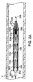
図1Aを参照すると、ステントグラフト100は、自己拡張型ステントグラフトであり、Dacron(登録商標)または延伸ポリテトラフルオロエチレン(ePTFE)などの任意の従来のグラフト材料から作られることができる管状グラフト102ならびに1つまたは複数の従来のステントおよび反転型または反転可能ステントを備える。例証的な実施形態では、波状の環状ステント104a〜104dは、管状グラフト102の外側表面に固定されて示され、反転型または反転可能ステント106は、管状グラフト102の内側表面に沿って管状グラフト102の内部に示される。ステント104a〜104dは、縫合糸または他の従来の手段を使用してグラフトに固定され、この実施形態では、以下でより詳細に述べるように、反転型または反転可能ステント106と違って、グラフト表面から離れて移動しないように固定される。1つの代替の実施形態では、ステント104a〜104dは、同じように、グラフト部材の内部に配置され、グラフト部材に固定される。
Referring to FIG. 1A,
管状グラフト102は、第1(または前)端102aと第2(または後)端102bと両者の間の中央部を有する。反転型または反転可能ステント106は、端102aに固定される。より具体的には、ステント106は、複数の頂部を有し、かつ、閉鎖リング構成で形成されている波状ワイヤを備える。ステント106の第1端は、頂部106aによって画定され、ステント106の他の端は、頂部106bによって画定される。例示的な実施形態では、ステント106が、その周りで図1Bに示す構成に旋回するかつ/または反転できる円周方向に向いたヒンジを形成するように、頂部106aだけが管状グラフト102に固定される。対照的に、ステント104a〜104dは、こうしたヒンジが無い状態で、その全長に沿って管状グラフト102に、または、ほぼその全長に沿って管状グラフト102に縫合されるかまたはその他の方法で固定される。図1Aに示す実施形態では、第1端(または終端部)102aは、頂部106aの一部分に折りたたまれ、縫合糸または接着剤などの任意の適した手段によって管状グラフト材料に固定される。代替の実施形態では、頂部106aは、管状グラフト102の内側表面、頂部106aに折り返されないグラフトに直接縫合されるのがよい。複数の縫合糸または縫合糸ループが、各頂部106aで使用され、または、単一縫合糸ループが各頂部で使用される。複数の縫合糸または縫合糸ループ配置構成あるいは単一縫合糸ループ配置構成は、縫合糸がステント106に沿って摺動し、ステント106と共に管状グラフトの端を引張るように、ある程度のたるみを提供するように作られるのがよい。さらなる変形では、頂部106aは、上述した固定手法のうちの任意の手法を使用して、管状グラフト102の外側表面に固定される。
図1Bおよび1Cを参照して、ステントグラフト100の装填について説明する。第1に、ステント106の自由端すなわち頂部106bは、外方に引張られ、ステントは、頂部106aと管状グラフト102との間に形成されたヒンジを中心に図1Bに示す位置に旋回し、それにより、ステント106が反転する。反転したステントは、管状グラフト端102aの前方に延在し、頂部106bがステントグラフトの中央部と反対方向を指した状態で、図1Bに示す位置に存在するように半径方向に圧縮され、その後、反転したまたは反転可能ステントは、拘束管212内に拘束される。ステントグラフトの残りは、半径方向に圧縮され、ステントグラフトは、管状シース202内に装填され、管状シース202は、図1Aおよび1Fに示されている別の配置を持つその非反転状態に戻る傾向がある荷重がかかったばねに似ている、ステント106がその反転状態にある状態で半径方向に圧縮された状態にステントグラフト100を拘束する。
With reference to FIGS. 1B and 1C, loading of the
図1D〜1Eを参照すると、管状グラフト102の十分な半径方向拡張後にステント頂部106bが解除されるように、ステントグラフト100が展開されると、ステント106は、図1Aに示すように、管状グラフト100の内側表面に戻り、ステント106が、その予め成形された構成のために、管状グラフト102の内側表面に対して半径方向力を加える。たとえば、ステント106の自由状態の径は、管状グラフト102よりわずかに大きくされる。あるいは、ステント106は、管状グラフト102の外側表面に戻るように展開されてもよい(たとえば、管状グラフトは、ステント106の解除前に半径方向に拡張することを許容されない)。たとえば、頂部106bは、図1Fに示すように、管状グラフト102の外側表面にわたって折り返されるように、シース202から展開されてもよい。ステント106はまた、以下でより詳細に述べるように、デバイスを固定するのを補助するオプションのフックを含んでもよい。
Referring to FIGS. 1D-1E, when the stent-
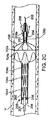
図2A〜2Dを参照すると、ステントグラフト送達システムの一実施形態が、展開前の装填された状態2Aおよび3つの部分的な展開状態(図2B、2C、および2D)で示され、全体が参照数字200で示される。送達カテーテルシステム200は、外側管と呼ばれるカテーテルすなわちシース202、中央部材204、およびガイドワイヤ205に沿って追従する内側ガイドワイヤ管201を含む。シース202、中央部材204、およびガイドワイヤ管201は、同軸であり、また、3者の間で相対的に軸方向に動くように構成される。ステントグラフト100は、半径方向に圧縮され、ステント106は、その全長に沿って(または、頂部106aが裏表にひっくり返らない場合、ほぼその全長に沿って)反転し、かつ、プッシャ部材または停止部206の前の外側管202の遠位端内に配置される。停止部206は、内側中央部材204と同心でありかつ内側中央部材204に固定され、そこを通るガイドワイヤ管201のためのアクセスを提供するための中央アクセスボアを有するディスクまたはリング形状構成を有する。反転したステント106は、外側管202内に配置され、かつ、テーパ付き先端208内に延在する管212内に保持される、すなわち、拘束される。簡潔にするために、4つの波状ステント部材104a〜104dを有するステントグラフト100が示される。x線透視法によって、シース202の遠位端の撮像を補助するために、テーパ付き先端208に隣接したカテーテルまたはシース202の遠位端部分の内部にx線不透過性リングが設けられてもよい。テーパ付き先端208は、カテーテルまたはシース202の遠位端がその上に配置されるスリーブを形成する管状の径が小さいセクション208aを有する。カテーテルシース202および径が小さいセクション208aは、両者間に摩擦嵌めを提供するサイズに作られ、たとえば、テーパ付き先端208が固定位置に保持され、カテーテルまたはシース202が引抜かれると、容易に分離できる。しかし、径が小さいセクション208aの内径は、拘束管212の外径よりわずかに小さいサイズに作られ、それにより、組立中に径が小さいセクション208a内に拘束管212が配置された後、カテーテル202が引抜かれると、拘束管212と径が小さいセクション208aの内側壁との間の嵌め合いが比較的強いため、拘束管212は、テーパ付き先端208内に留まる。
2A-2D, one embodiment of a stent graft delivery system is shown in a pre-deployment loaded state 2A and three partially deployed states (FIGS. 2B, 2C, and 2D), generally designated by reference numerals. 200.
送達システム200のカテーテルが補綴具の展開のための所望の部位に配置されると、停止部206およびガイドワイヤ管201を有する中央部材204は、固定して保持され、外側管、カテーテルまたはシース202は、ステントグラフトの近位端が徐々に露出され、拡張することを許容されるように引抜かれる。テーパ付き先端208は、上述したように、頂部106aを拘束する拘束部として働く管状拘束部212の一部分が配置される環状凹所または空洞210を有する。したがって、停止部206は、ステントグラフトが展開されると、ステントグラフトの遠位端に係合するサイズに作られる。シース202の近位端、中央部材204、およびガイドワイヤ管201は、結合され、当技術分野で知られているように、医師またはインターベンショナリストの操作に適するハンドルによって操作される。拘束管212は、頂部106aの後の展開フェーズ中に頂部106aの拡張を可能にする前に、半径方向に圧縮された構成で頂部106aを保持するように構成される。あるいは、その開示が、参照によりその全体が本明細書に組込まれる、Wright他に付与され、「Controlled Deployment Delivery System」という名称の共有の米国特許7,264,632号明細書に記載されるステントグラフト展開システムの任意のシステムが、ステントグラフト送達システム200に組込まれる。使用される他のステントグラフト送達システムは、その開示が、参照によりその全体が本明細書に組込まれる、2006年11月14日に出願され、「Delivery System for Stent−Graft With Anchoring Pins」という名称の共有の米国特許出願11/559,754号に記載される、Medtronic,Inc(ミネアポリス、ミネソタ州).によって製造されたEndurant(登録商標)ステントグラフト送達システムを含む。
When the catheter of the
図2Bを参照すると、カテーテルシース202は、部分的に後ろに引張られ、かつ、補綴具の一部分が部分的に拡張した状態で示される。この部分的に引抜かれた位置では、補綴具の近位端は束縛され、補綴具の近位端の解放前に、所望される場合、補綴具が再配置される(たとえば、長手方向にまたは回転して移動される)ことを可能にする。以下でより詳細に述べるように、外科医またはインターベンショナリストは、展開中にx線透視を使用して、補綴具の監視された動きに基づいて、補綴具の再配置が所望されるかどうかを判定できる。
Referring to FIG. 2B, the
図2Cを参照すると、ステントグラフト100の十分な長さが拡張した後、シース202および中央部材204が、固定して保持され、ガイド管201(テーパ付き先端208にしっかり固定され、同様にガイドワイヤ205に沿って追従する)が、カテーテルシース202からテーパ付き先端208をさらに分離し、また、ステント106の一部分を解放し、かつ、ステント106が拡張し始めることを可能にするように進められる。テーパ付き先端208がさらに進むにつれて、管状拘束部212が、頂部106bを解放する(図2D)。反転したステント106は、その後、点線で示すように管状グラフト102内にある非反転状態にひっくり返り、グラフト材料を通して血管「V」に対して半径方向外方の力を加えて、ステントグラフトを固定するための増大した力を提供する。この点で、ステント106は、管状グラフトおよび血管壁に対して外方に向いたこうした半径方向力を加える能力を高める所定の構成を備える。一実施形態では、ステント106は、こうした半径方向力を提供するかまたは倍加させるために円錐またはテーパ付き形状で予備成形される。
Referring to FIG. 2C, after a sufficient length of the
図2E〜2Gは、テーパ付き先端208'内に保持される頂部106aから延在するオプションのフック108aを有する図1Aの反転したステントの展開を略図で示す。テーパ付き先端208'は、図2E〜2Gにおいて略図で示され、テーパ付き先端208と同じ構成を有し、したがって、図2A〜2Dに示す、径が小さいセクション208aを受取るカテーテルまたはシースと同様の径が小さいセクション208a'を含むのがよい。図2Eは、図1Bに示す状態などの反転しかつ半径方向に圧縮された状態にステント106が拘束された拘束管212から解除されたステント106を示す。図2Fは、ステントグラフト100内部で移動するステント106およびステントグラフトに貫入するフック108aを示す。図2Gは、フック108aが動脈瘤「A」の上の血管「V」の壁の部分を貫通して完全に係合した状態での、ステントグラフトの内側表面に沿って図1Aに示す位置と同様の位置にステント106が戻った後のステント106を示す。
2E-2G schematically illustrate the deployment of the inverted stent of FIG. 1A with an
図2H〜2Jは、本発明による別の実施形態の展開を略図で示し、管状グラフト102などの管状グラフトを含むステントグラフト100'を備え、また、ステント104a、104b、104c、104dが上述したステントグラフト100に組込まれるのと同じ方法で、ステントグラフト100'に組込まれたステントを含んでもよい。例示のために、ステント104aおよび104bが図2Hに示される。しかし、この実施形態では、反転可能ステント(反転可能ステント106')は、(1)管状グラフト102の内部にあるとき反転し、(2)管状グラフト102の外部にあるとき自由状態にあり、そうでなければ、送達シースまたはテーパ付き先端およびその管状拘束部によって半径方向に束縛されない。そうでなければ、ステント106およびステント106'は同じである。ステント106'は、頂部106aおよび106bに相当する頂部106'aおよび106'bを含む。頂部106'aは、管状グラフト端の周囲102a'に沿って管状グラフト102aの遠位端102aに、あるいは、管状グラフト102の内側表面または外側表面に旋回可能に接続されて、ヒンジ点として働く各頂部106'a用の単一取付け点を提供する。管状グラフト102に対する頂部106'aの全ての取付けは、ステント106'の一端がその周りに旋回できる円周方向に配列されたヒンジ点のセットを協働して生成する。ヒンジは、各頂部106'aの周りでかつ管状グラフトを通って延在する単一縫合糸ループを使用して形成される。さらなる代替法では、頂部106'aは、管状グラフト102と、頂部が管状グラフト102の内側表面上に設置される場合、管状グラフト102の内側表面上に、頂部が管状グラフト102の外側表面上に設置される場合、管状グラフト102の外側表面上に設置されるグラフト材料の別の環状リングとの間に挟まれる。この構成によって、ステント106'が半径方向外側の力を提供する反転した構成でステントグラフト内にステント106'を存在させるために、頂部106'aは、ステントグラフトの外側の位置からステントグラフト100'の内部に付勢される。ステントグラフトの内部の反転した位置に頂部106'aを付勢するために、任意の適したメカニズムが使用される。ステントグラフト100'は、血管内のターゲット部位に設置され、完全にまたは部分的に展開される。ステント106'は、その後、管状グラフト102の内部に押込まれるまたは引張られる。これは、任意の適した手段で行われる。
2H-2J schematically illustrate the deployment of another embodiment according to the present invention, comprising a
図2Hに示す実施形態では、ステント頂部106'bがテーパ付き先端スリーブセクション208'a内に留まっている、ステント106'の部分的解除後に、テーパ付き先端またはステント頂部拘束部208'が引抜かれる。テーパ付き先端208'は、反転可能ステント106'を、その円周方向に向くヒンジ点を中心に管状グラフト102内の位置まで引張り、旋回させるために引抜かれる。テーパ付き先端208'は、テーパ付き先端208と同じ構成を有し、図2A〜2Dに示す径が小さいセクション208aを受取るカテーテルまたはシースと同様の径が小さいセクション208'aを含んでもよい。図2Iは、拘束部208'のさらなる引抜きを示し、図2Jは、その反転位置のステント106'を示し、そのばね特性の結果として、ステント106'は、動脈瘤「A」の上の血管「V」の壁に対して半径方向外方の力を加える。その後、拘束部208'は取除かれる。所望である場合、別個のバルーンカテーテル上に搭載されたバルーンなどの別個の拡張部材が、ステント106'を半径方向に拡張するために使用される。
In the embodiment shown in FIG. 2H, the tapered tip or stent top restraint 208 'is withdrawn after partial release of the stent 106' where the stent top 106'b remains in the tapered tip sleeve section 208'a. . The tapered
他の反転メカニズムが使用されてもよい。たとえば、プルワイヤまたは縫合糸が、各頂部106'aに固定され、各ワイヤまたは縫合糸が、カテーテル202を通して後方に延ばされる。ステントグラフト100'は、ステント106'が、管状グラフト102の外でかつそれを超え、ステント106'がそこから延在する端部分にほぼ平行に延在するように展開される。したがって、ステント106'は、テーパ付き先端208の外側にあり、血管「V」の内壁に沿って延在する。ワイヤまたは縫合糸は、管状グラフト内でステントが反転状態になるように、ステント頂部106'aを管状グラフト102内に引張るように引張られる。この場合、テーパ付き先端208'は、ステント106'を内向きに引張るために使用されないが、たとえば、図2Bまたは2Eに示すように、ステント106'を解除するために進められることができ、その後、ワイヤまたは縫合糸は、ステント106'を反転させるために引張られる。ワイヤまたは縫合糸は、その後、従来の腔内ワイヤ/縫合糸切断メカニズムを使用して切断される。さらなる変形では、ワイヤまたは縫合糸は、各ワイヤまたは縫合糸の一端が頂部106'bに固定され、ワイヤまたは縫合糸は、各ワイヤまたは縫合糸の他端がテーパ付き先端208'に固定される場合に、たとえば、テーパ付き先端208'の前端に対向するスリーブ208'aの後端において使用される。ステント106'が、完全に解除され、血管「V」の内壁に沿って配置された後、テーパ付き先端は、ステントグラフト100内部で図2Jに示す位置までステントを引張るために引抜かれる。ワイヤまたは縫合糸は、その後、上述したように切断される。
Other inversion mechanisms may be used. For example, a pull wire or suture is secured to each apex 106 ′ a and each wire or suture is extended posteriorly through the
ステント106'に関して、その開示が、参照によりその全体が本明細書に援用される、2008年3月21に出願されたGlynnの米国特許出願12/052989号に記載される装置などの、任意の他の適した送達装置もまた使用される。
With respect to the
図2Kは、使用可能で、また、ステントグラフトおよび外側シースが無い状態で示される、別のステントグラフト送達システムの一部分の部分断面図である。図2Kに示すメカニズムは、その開示が、参照によりその全体が本明細書に組込まれる、2006年11月14日に出願され、「Delivery System for Stent−Graft With Anchoring Pins」という名称の、Mitchell他に付与された共有の米国特許出願11/559,754号に記載される。ステントグラフト送達システム600は、柔軟性があり、窮屈でかつ蛇行状の血管内で追従性を提供できるテーパ付き先端602を含む。テーパ付き先端602は、隣接する部材に接続し、テーパ付き先端602を通したガイドワイヤの通過を可能にするための、内部にガイドワイヤ管腔604を含む。弾丸形状先端などの他の先端形状も使用される。
FIG. 2K is a partial cross-sectional view of a portion of another stent graft delivery system that is usable and shown without a stent graft and outer sheath. The mechanism shown in FIG. 2K is filed on November 14, 2006, the disclosure of which is incorporated herein by reference, Mitchell et al., Entitled “Delivery System for Sent-Graft With Anchoring Pins”. In commonly-owned US patent application Ser. No. 11 / 559,754. The stent
内側管606は、内部に、管腔、たとえば、ガイドワイヤ管腔を画定する。内側管606の遠位端607は、テーパ付き先端602内に位置し、テーパ付き先端602に固定される。すなわち、テーパ付き先端602は、内側管606上に搭載される。図2Kに示すように、内側管606の管腔は、テーパ付き先端602のガイドワイヤ管腔604と流体連通し、それにより、ガイドワイヤは、内側管606を通り、遠位端607を出て、テーパ付き先端602のガイドワイヤ管腔604を通り、テーパ付き先端602の遠位端603から出るように送られる。
Inner tube 606 defines a lumen therein, eg, a guidewire lumen. The distal end 607 of the inner tube 606 is located within the tapered
テーパ付き先端602は、径が徐々に増加するテーパ付き外側表面608を含む。より詳細には、テーパ付き外側表面608は、遠位端603で最小径を有し、遠位端603から近位に、すなわち、オペレータ(または、ステントグラフト送達システム600のハンドル)の方向に径が徐々に増加する。
テーパ付き外側表面608は、テーパ付き先端602の主シース隣接表面(肩部)610まで近位に延在する。主シース隣接表面610は、ステントグラフト送達システム600の長手方向軸「LA」に垂直な環状リングである。
The tapered outer surface 608 extends proximally to the main sheath adjacent surface (shoulder) 610 of the tapered
テーパ付き先端602は、さらに、主シース隣接表面610から近位に延在する(先端)スリーブ612を含む。一般に、スリーブ612は、テーパ付き先端602の近位端にある。スリーブ612は、主シース隣接表面610から近位にかつ長手方向に延在する中空円柱管である。スリーブ612は、外側円柱表面614および内側円柱表面616を含む。
ステントグラフト送達システム600は、さらに、外側管618の遠位端619に位置しかつそこに固定されたスピンドル620を有する外側管618を含む。スピンドル620は、円柱外側表面を有するスピンドル本体622、スピンドル本体622から半径方向外側に突出する複数のスピンドルピン624、およびスピンドル本体622から半径方向外側に突出する複数の主シースガイド626を含む。主シースガイド626は、(先端)スリーブ612上の所定位置内に主シースを誘導する(たとえば、図2Lを参照されたい)。
The stent
図2Kに示すように、スピンドル620は、スピンドルピン624が、スリーブ612の内側円柱表面に直接隣接する、すなわち、接触するように、スリーブ612の内側を摺動するように構成される。スピンドルピン624は、スピンドル本体622からスリーブ612に向かって、かつ、スリーブ612まで延在する。一般に、スピンドルピン624がスピンドル本体622からそこまで延在する径は、スリーブ612の内側円柱表面の径にほぼ等しいか、または、それより僅かに小さく、スピンドルピン624が、スリーブ612の内部にしっかり嵌合することを可能にする。環状空間628が、内側円柱表面616とスピンドル本体622との間に存在する。
As shown in FIG. 2K, the
内側管606は、内部にあり、外側管618およびスピンドル620を通って延在する。内側管606、したがって、テーパ付き先端602は、外側管618、したがって、スピンドル620に対して長手方向軸Lに沿って移動して(長手方向に移動して)、以下でさらに説明するように、ステントグラフトの近位端を解除する。
Inner tube 606 is internal and extends through
図2Lは、展開前で引抜き前の位置で、引抜き可能主シース202内に装填されたステントグラフト100を含む図2Kのステントグラフト送達システム600の部分断面図である。
2L is a partial cross-sectional view of the stent-
主シース202は、中空管であり、内部に管腔207を画定し、管腔207を通して、外側管618および内側管606が延在する。主シース202は、図2lにおいて、展開前で引抜き前の位置にある。主シース202は、外側管618/スピンドル620、したがって、ステントグラフト100に対して、長手方向軸「LA」に沿って近位に移動して(引抜きと呼ばれることがある)、以下でさらに説明するように、ステントグラフト100の一部分を展開する。上述したように、ステントグラフト202は、その半径方向に束縛された位置から解除されると自己拡張するような、自己拡張型ステントグラフトである。この実施形態によれば、ステントグラフト100は、先に説明したように、管状グラフト102と、支持構造(ステント104a〜104d)と、管状グラフトに取り付けられた反転型または反転可能ステント106を含む。管状グラフト102は、近位端または前端102aおよび遠位端または後端102bを含む。
The
図2Lに示すように、ステントグラフト100は、外側管618およびスピンドル620にわたって半径方向に束縛された構成になる。ステントグラフト100は、主シース202内に位置し、主シース202によって半径方向に圧縮される。反転型または反転可能ステント106は、半径方向に束縛され、スピンドル本体622とスリーブ612の内側円柱表面616との間の環状空間628内の所定位置に保持される。
As shown in FIG. 2L, the
一般に、ステントグラフト100のグラフト材料は、主シース202によって半径方向に束縛され、反転型または反転可能ステント106の前部分は、スリーブ612によって半径方向に束縛され、ステントグラフト100のグラフト材料および反転型または反転可能ステント106の順次でかつ独立した展開を可能にする。
In general, the graft material of the
主シース202は、テーパ付き先端602の主シース隣接表面610に隣接するかまたは主シース隣接表面610に当接する遠位端202Dを含む。遠位端202Dは、スリーブ612の周りにしっかり嵌合し、一実施形態では、スリーブ612の外側円柱表面614上で半径方向内向きに軽く押す。
図2Mは、引抜き可能主シース202が部分的に引抜かれた状態での、図2Lのステントグラフト送達システム600の部分断面図である。ここで図2Mを参照すると、主シース202は、遠位端202Dが、テーパ付き先端602から離間するように、部分的に引抜かれている。さらに、主シース202の引抜きのため、ステントグラフト100の近位部分110が、拡張し、部分的に展開されている。
FIG. 2M is a partial cross-sectional view of the stent-
近位部分110が部分的に展開されているだけであり、反転型または反転可能ステント106の一部分が半径方向に束縛され、未展開状態であるため、ステントグラフト100は、初期配置が望ましい配置と言えない場合、再配置できる。より詳細には、ステントグラフト100を再配置するために、主シース202の引抜きが停止される。ステントグラフト送達システム600は、その後、ステントグラフト100を再配置するために移動される。たとえば、ステントグラフト100がそこに展開される血管壁の損傷を与える実質的なリスクが無い状態で、ステントグラフト100は、近位にまたは遠位に回転されるかまたは移動される。
Because the
さらに、主シース202が引抜かれるにつれて、反転型または反転可能ステント106が固定され、かつ、所定張力に維持され、一実施形態では、ステントグラフトの遠位端(図示せず)が、主シース202内で自由に動くため、主シース202の引抜き中におけるステントグラフト100の束形成が回避される。束形成を回避することによって、引抜き中の主シース202に対するステントグラフト100の摩擦抵抗が最小になり、したがって、主シース202のスムーズでかつ容易な引抜きを促進する。
Further, as the
ステントグラフト100が適切に配置されると、頂部106bは、解除されて、先に説明したように、反転型または反転可能ステントが、ステントグラフト100の内部に戻ることが可能になる(たとえば、図1Aを参照されたい)。
When the
図2Nは、反転型または反転可能ステントの展開後の図2Mのステントグラフト送達システム600の部分断面図である。ここで図2Mを参照すると、テーパ付き先端602は、ステント106(図からは隠れて見えない)が、上述したステントグラフト100の内部の位置に戻る(たとえば、図1Aを参照されたい)ように、ステント106の頂部106bの近位端を露出するようにスピンドル620に対して進められる。必要である場合、ステント106が図1Aに示すようなステントグラフトの内部の位置に戻るためのクリアランスを提供するために、スピンドル620がステントグラフト100内に引抜かれる。
FIG. 2N is a partial cross-sectional view of the stent-
別の実施形態では、主シース202は、反転型または反転可能ステント106の解除の前に、完全に引抜かれる。例示のため、図2Mに示す展開ステージで部分的に引抜かれる代わりに、主シース202は、ステント106が依然として半径方向に束縛されている間に、完全に引抜かれる。
In another embodiment, the
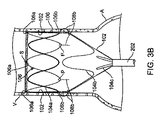
図3Aおよび3Bは、端拘束部212が無く(または、ステントグラフト展開前に、拘束部208'が進められており)、かつ、頂部106bから延在するオプションのフック108bを有する図1Aのステントグラフトの別の展開方法を略図で示す。図3Aは、シース202から展開された後の反転型ステントを示す。反転型ステントは、フック108bが動脈瘤「A」の上の血管「V」に貫入した状態で、拡張状態にある。図3Bは、図1Fに示すように、自己反転し、管状グラフト102の外側表面に沿う位置に戻った後の反転型ステントを示す。反転型ステント106は、自己反転するため、管状グラフト端102aを、図3Bに示す位置まで反転型ステント内に引張る。綿球Pは、フック108bのベースに設けられ、血流が頂部106bを血管壁内に押込むリスクを最小にするかまたはなくす。反転型または反転可能ステントの頂部の数は、用途に応じてまたは所望に応じて変わる。たとえば、4〜8の頂部106aが、対応する数の頂部106bと共に使用される。しかし、より多いかまたはより少ない頂部を有する反転型または反転可能ステントもまた使用される。
FIGS. 3A and 3B show the stent graft of FIG. 1A without end restraint 212 (or with
非二又分岐ステントグラフト構成が示されたが、本明細書に述べる反転型または反転可能ステントは、二又分岐(bifurcated)ステントグラフトにおいて使用されうり、反転型または反転可能ステントは、通常、二又分岐に対向する端に沿って(たとえば、AAA二又分岐ステントグラフトの遠位端に沿って)配置されることになる。より多くのまたはより少ないステント104または二又分岐構成を含む他の構成が使用される。たとえば、二又分岐ステントは、その遠位端に反転型または反転可能ステントを、そうでなければ、他の端に1つステントだけを備えうり、それにより、送達のために半径方向に圧縮されると、減少したプロファイルを可能にする。
Although a non-bifurcated stent graft configuration has been shown, the reversible or reversible stents described herein can be used in bifurcated stent grafts, and reversible or reversible stents are usually bifurcated. (E.g., along the distal end of an AAA bifurcated stent graft). Other configurations are used, including more or
図4A、4B1、4B2、および4Cを参照すると、反転型または反転可能ステントを有する別の自己拡張型ステントグラフトが、提示された実施形態の原理に従って示される。この実施形態は、別のステントグラフトの開窓内に分枝血管カバー付きステントを生体内原位置で固定することに伴う難問に対処する。この実施形態によれば、反転型または反転可能ステントは、分枝血管ステントグラフト内で、胸部大動脈瘤用適用形態の場合、ステントグラフトの近位端に、または、腹部大動脈瘤適用形態の場合、遠位端に設けられる。反転型または反転可能ステントは、展開されると、自分自身の上に折り返す能力、および、開窓の周りで開窓式ステントグラフトのエリアに係合する能力をステントグラフトに与える。ステントグラフトはまた、開窓に隣接した反転型または反転可能ステントの最適な留置を補助するために、視覚マーカ(たとえば、x線不透過性マーカ)を有してもよい。この構成によって、開窓式ステントグラフトにおける亀裂伝播、ステントグラフト移動、および分枝血管における接合されたステントグラフト間の漏洩の1つまたは複数のリスクが低減される。 With reference to FIGS. 4A, 4B1, 4B2, and 4C, another self-expanding stent graft having an invertible or invertible stent is shown in accordance with the principles of the presented embodiment. This embodiment addresses the challenges associated with anchoring a branch vessel covered stent in situ in another stent graft fenestration. According to this embodiment, the reversible or reversible stent is within the branch vessel stent graft, at the proximal end of the stent graft for the thoracic aortic aneurysm application, or distal for the abdominal aortic aneurysm application. Provided at the end. When deployed, an invertible or invertible stent provides the stent graft with the ability to fold over itself and engage the area of the fenestration stent graft around the fenestration. The stent graft may also have a visual marker (eg, a radiopaque marker) to assist in optimal placement of the inverted or invertible stent adjacent to the fenestration. This configuration reduces one or more risks of crack propagation in the fenestration stent graft, stent graft migration, and leakage between the joined stent grafts in the branch vessel.
図4Aを参照すると、自己拡張型ステントグラフトであるステントグラフトまたはカバー付きステント300は、管状グラフト302を含み、管状グラフト302は、第1端302aと第2端302bと両者間の中央部を有する。カバー付きステント300は、さらに、ステント104a〜104dが管状グラフト102に固定されるのと同じ方法で、管状グラフト302に固定される複数のステント(たとえば、302a、302b、302c、および302d)を含む。波状の反転型または反転可能ステント306は、一端に頂部306aを、他端に頂部306bを有する。頂部306aは、管状グラフト302に旋回可能に固定され、ステント頂部106aが、管状グラフト102に固定されるのと同じ方法で固定される。反転型または反転可能ステント306が、その中に配置される開窓式ステントグラフトの内側表面に向かって跳ね返ると、封止要素を形成するように、反転型または反転可能ステント306は、図4Aに示すようにグラフト材料310によって覆われる。この点で、反転型または反転可能ステント306は、封止要素と呼ばれる。封止要素の外側表面に当たる血流は、シールを高める。あるいは、反転型または反転可能ステント306用のグラフト被覆は、製造中に管状グラフト306と一体に形成される。図4Aは、反転した状態から自由状態に戻った後に、花に似た構成を有する反転型または反転可能ステント306を示す。反転型または反転可能ステント306は、図5Aおよび5Bの実施形態のために略図で示すように、その波状部または花弁が、図4B1に示す位置から180°まで拘束されないときに、グラフト端302bに向かって開花し、折り返して、反転型または反転可能ステント306および/またはそのグラフト材料310と、ステント306および/またはそのグラフト材料310が係合する表面との間に(ステントが、グラフト材料の内側表面に固定されているか、外側表面に固定されているかに応じて)有意な接触を可能にするように構築される。
Referring to FIG. 4A, a stent graft or covered
図4B1を参照すると、当技術分野で知られているように、半径方向の支持を提供するオプションのばねコイル322およびx線不透過性マーカ320を有するステントグラフト(カバー付きステント)300が示される。
Referring to FIG. 4B1, a stent graft (covered stent) 300 with an
図4B2を参照すると、ステントグラフト300は、半径方向に圧縮され、頂部306bが管状グラフト302の中央部と別の方向に向いた状態でカテーテル202内に拘束される。
Referring to FIG. 4B2, the
図4Cは、シース202が取除かれた後に、その自由状態に向かって跳ね返る反転型または反転可能ステント306を示す。
FIG. 4C shows a reversible or
反転型または反転可能ステント306は、図4A〜4Cにおいて、また、図4B1で最もよく見られるように、6つの頂部306bを有する6つの花弁のある構成を持って示される。しかし、より多くのまたはより少ない頂部が使用される。実施形態のために、5つの花弁のある構成が、図4Dに示され、8つの花弁のある構成が、図4Eに示され、反転型または反転可能ステントは、頂部306'a、306'bおよび306''a、306''bをそれぞれ有する数字306'および306''で示される。反転型または反転可能ステント306'および306''用のグラフト被覆310'および310''は、先に述べたように、製造中に管状グラフト302と一体に形成される。
Inverted or
図4Fは、図4Eに示す実施形態の代替の実施形態を示し、花弁間の空間が、グラフト材料307で覆われ、反転可能ステント306'''が、覆われたステント300の中心線軸から約90°に向いたとき、実質的に緩いままになるサイズに作られる。その他の点で、図4Eおよび4Fの実施形態は同じであり、反転可能ステント306''は、ステント306'''と同じ構成を有し、対応する頂部306''aおよび306'''aならびに306''bおよび306'''bを有し、グラフトカバー310''は、グラフトカバー310'''と同じ構成を有する。図4Fの構成は、ステント頂部306'''b(またはそのグラフトカバー)が、それに接して隣接構造に接触状態となるステントグラフト表面または血管壁に対して、実質的に緩い材料またはセクション307を血圧が付勢する機会を提供する。材料またはウェッビング307は、血流に対する障壁を提供する織物などの任意の適した材料であり、折りたたみ可能かまたは伸張可能な材料であり、波状の反転可能ステント306'''の隣接する波状部間のグラフト材料310'''に縫い付けられる。
FIG. 4F shows an alternative embodiment of the embodiment shown in FIG. 4E, where the space between the petals is covered with
図5Aを参照すると、胸部送達適用形態が示される。ステント104a〜104dと同様の複数のステントを含む主ステントグラフト400は、動脈瘤をバイパスするために大動脈内に配置され、左鎖骨下動脈「L」へのアクセスを提供するために開窓を持って示される。分枝カバー付きステント300は、シース202内に拘束されながら、部位まで送達され、開窓を通して、左鎖骨下動脈内に送られる。シースが引抜かれ、カバー付きステント300が展開される。反転型ステント306は、ステント306またはそのカバーが、開窓の周りでステントグラフト400の内側表面に封止係合するように、管状グラフト302の中央部に向かって自己反転するまたは跳ね返る。
With reference to FIG. 5A, a chest delivery application is shown. A
図5Bを参照すると、カバー付きステント300は、ステント104a〜104dと同様の複数のステントを含み、動脈瘤「A」をバイパスするために腹部大動脈内に配置される二又分岐ステントグラフト500内の開窓を通してシース202を介して送達される。ステントグラフト500は、腎動脈に相当する分枝血管BV1およびBV2のそれぞれに対するアクセスを提供するために両側に開窓を有する。カバー付きステント300は、カテーテルシース202を使用して分枝血管BV1内に導入され、カテーテルシース202は、その後、引抜かれて、反転型ステントが、管状グラフト302の中央部に向かって自己反転するまたは跳ね返り、開窓の周りでステントグラフト500の内側表面に封止係合するように、カバー付きステント300が展開される。別のステントグラフト300は、その後、分枝血管BV2内で同様に展開される。カバー付きステントの展開は、カバー付きステントが主血管から導入される事例において、ハブから先端への(hub to tip)展開システムおよび方法を使用して展開されうり、カバー付きステントのハブ(中央)部(または近位端)が、最初に展開されて、反転型ステントが、最初に出現し、カバー付きステントの残余部がその中に展開される側部分枝開口に隣接するステントグラフト壁に接して配置されることが可能になる。主ステントグラフト本体の外側から側部分枝開口内へのかつ側部分枝開口を通る逆行性展開が使用される場合、通常の先端からハブへの展開は、最初に、反転型ステントを展開して、円柱カバー付きステント本体を展開する前に、反転型ステントが正しく配置されることを可能にする。
Referring to FIG. 5B, covered
さらに、本明細書で述べるステントまたは波状部材はいずれも、ニチノールなどの任意の適したステント材料から作られる。波状構成は、従来の技法を使用して提供され、波状構成を形成するように平坦ボードにワイヤが巻き付けられることを可能にするように、複数のペグが、平坦ボード上に搭載される。ワイヤは、ペグの周りに締められて、平面の波状要素を形成し、平面の波状要素は、熱処理されて、ワイヤをその構成で熱固定し、それにより、当技術分野で知られているように、記憶固定構成(memory set configuration)が形成される。要素の端は、溶接または任意の他の適した手段によって共に固定されて、閉鎖リングが形成される。反転型または反転可能ステント106を作る1つの代替の方法において、ペグは、波状構成でワイヤを巻くことを可能にするように、円柱マンドレル上に搭載される。ワイヤは、波状構成でペグの周りに締められ、端が、互いに固定される。波状リングは、その後、記憶固定構成を与えられるために熱処理される。この手法は、反転した後に、ステントが非反転状態に自己反転するための大きなばね作用を提供する。
Further, any of the stents or undulating members described herein are made from any suitable stent material, such as nitinol. A corrugated configuration is provided using conventional techniques, and a plurality of pegs are mounted on the flat board to allow the wire to be wrapped around the flat board to form the corrugated configuration. The wire is clamped around the peg to form a planar wavy element that is heat treated to heat fix the wire in its configuration, thereby as known in the art At the same time, a memory set configuration is formed. The ends of the elements are secured together by welding or any other suitable means to form a closure ring. In one alternative method of making an invertable or
本明細書で述べる実施形態の多くの利点の中には、低いステントグラフト送達プロファイルがある。より具体的には、反転型または反転可能ステントは、反転型または反転可能ステントがその一部を形成するステントグラフトの主本体の外側から送達される。 Among the many advantages of the embodiments described herein are low stent graft delivery profiles. More specifically, the reversible or reversible stent is delivered from outside the main body of the stent graft, of which the reversible or reversible stent forms part.
本明細書で述べる任意の1つの実施形態で述べる任意の特徴は、本明細書で述べる他の実施形態または特徴の任意のものの任意の他の特徴と組合わされる。さらに、本明細書で開示されるデバイスおよび方法の変形および変更は、当業者に容易に明らかになる。 Any feature described in any one embodiment described herein is combined with any other feature of any of the other embodiments or features described herein. Further, variations and modifications of the devices and methods disclosed herein will be readily apparent to those skilled in the art.
Claims (15)
第1の終端部と、第2の終端部と、両者の間の中央部とを有する管状グラフトと、
複数の頂部と、前記頂部の第1の群によって少なくとも部分的に画定される第1の端と、前記頂部の第2の群によって少なくとも部分的に画定される第2の端とを有する波状ステントとを備え、
前記波状ステントの頂部の第1の群が前記管状グラフトの前記第1の終端部で前記管状グラフトに固定され、
前記波状ステントが、
前記波状ステントが前記第1の終端部に固定された前記第1の端から前記管状グラフトの外側に配置された前記第2の端まで略長手方向に延び、前記中央部と反対方向を指している反転状態と、
前記波状ステントが、前記第2の端が前記管状グラフトの第1および第2の終端部の間に配置されるように、前記第1の終端部に固定された前記第1の端から前記管状グラフトの中央部に向かって略長手方向に延びる非反転状態と、をとることができ、
非反転状態で、前記頂部の第2の群が前記管状グラフトの内面または外面に当接する、
ことを特徴とする管状補綴具。 A tubular prosthesis,
A tubular graft having a first end, a second end, and a central portion therebetween;
An undulating stent having a plurality of tops, a first end at least partially defined by the first group of tops, and a second end at least partially defined by the second group of tops And
A first group of apexes of the corrugated stent is secured to the tubular graft at the first end of the tubular graft;
The wavy stent is
The corrugated stent extends substantially longitudinally from the first end secured to the first terminal end to the second end disposed on the outside of the tubular graft, pointing in a direction opposite to the central portion. With the inverted state,
The corrugated stent is tubular from the first end secured to the first end such that the second end is disposed between the first and second end of the tubular graft. A non-inverted state extending substantially in the longitudinal direction toward the center of the graft,
In a non-inverted state, the second group of tops abuts the inner or outer surface of the tubular graft;
A tubular prosthesis characterized by the above.
請求項1に記載の管状補綴具。 The corrugated stent forms a closure ring;
The tubular prosthesis according to claim 1.
請求項1に記載の管状補綴具。 When the corrugated stent is in a non-inverted state, it is placed against one of the inner and outer surfaces of the tubular graft;
The tubular prosthesis according to claim 1.
請求項1に記載の管状補綴具。 A portion of the undulating stent expands radially when in a non-inverted state;
The tubular prosthesis according to claim 1.
請求項4に記載の管状補綴具。 When the corrugated stent is in a non-inverted state, it is folded toward the central portion;
The tubular prosthesis according to claim 4.
請求項4に記載の管状補綴具。 The corrugated stent is covered by a graft material;
The tubular prosthesis according to claim 4.
前記波状ステントが、星形状構成を有する、
請求項6に記載の管状補綴具。 The graft material forms part of the tubular graft;
The corrugated stent has a star-shaped configuration;
The tubular prosthesis according to claim 6.
請求項1に記載の管状補綴具。 Only the undulating stent is secured to the tubular graft through the first group of the apex.
The tubular prosthesis according to claim 1.
請求項1に記載の管状補綴具。 A plurality of sutures securing a plurality of tops of the first group to the tubular graft material;
The tubular prosthesis according to claim 1.
単一縫合糸ループだけが、前記複数の前記第1の群の頂部の各頂部を前記管状グラフト材料に固定する、
請求項9に記載の管状補綴具。 The suture is slidable along the wavy stent;
Only a single suture loop secures each top of the plurality of tops of the first group to the tubular graft material.
The tubular prosthesis according to claim 9.
請求項1に記載の管状補綴具。 A portion of the terminal portion is folded into a portion of the top of the first group and secured to the tubular graft material;
The tubular prosthesis according to claim 1.
請求項1に記載の管状補綴具。 The top of the first group is secured to the inner surface of the tubular graft;
The tubular prosthesis according to claim 1.
請求項1に記載の管状補綴具。 And further comprising a plurality of hooks, each hook extending from a top of a plurality of the first group of tops and / or each hook being a top of a plurality of the second group of tops. Extending from the
The tubular prosthesis according to claim 1.
請求項1に記載の管状補綴具。 A self-expanding stent graft,
The tubular prosthesis according to claim 1.
遠位展開端および近位端を有するシースと、
請求項1ないし14のいずれか1項に記載された半径方向に圧縮されたステントグラフトと、を備え、
前記波状ステントが、前記第2の群の頂部が前記シースの前記遠位展開端の方に向いた状態で反転される、
ことを特徴とするシステム。 A tubular prosthesis delivery system comprising:
A sheath having a distal deployed end and a proximal end;
A radially compressed stent graft according to any one of the preceding claims,
The corrugated stent is inverted with the top of the second group facing toward the distal deployed end of the sheath;
A system characterized by that.
Applications Claiming Priority (3)
| Application Number | Priority Date | Filing Date | Title |
|---|---|---|---|
| US12/109,076 | 2008-04-24 | ||
| US12/109,076 US20090270971A1 (en) | 2008-04-24 | 2008-04-24 | Prosthesis Fixation Apparatus and Methods |
| PCT/US2009/039636 WO2009131823A1 (en) | 2008-04-24 | 2009-04-06 | Endoprosthesis with retaining means and methods of use |
Publications (3)
| Publication Number | Publication Date |
|---|---|
| JP2011518610A JP2011518610A (en) | 2011-06-30 |
| JP2011518610A5 JP2011518610A5 (en) | 2012-05-31 |
| JP5849699B2 true JP5849699B2 (en) | 2016-02-03 |
Family
ID=40671360
Family Applications (1)
| Application Number | Title | Priority Date | Filing Date |
|---|---|---|---|
| JP2011506341A Expired - Fee Related JP5849699B2 (en) | 2008-04-24 | 2009-04-06 | Prosthesis fixing device and method |
Country Status (4)
| Country | Link |
|---|---|
| US (1) | US20090270971A1 (en) |
| EP (1) | EP2303188A1 (en) |
| JP (1) | JP5849699B2 (en) |
| WO (1) | WO2009131823A1 (en) |
Families Citing this family (29)
| Publication number | Priority date | Publication date | Assignee | Title |
|---|---|---|---|---|
| DE102007019058A1 (en) * | 2007-04-23 | 2008-10-30 | Stengel, Max, Dr.Dr. | Vascular implant for the treatment of an aneurysm |
| US8114147B2 (en) * | 2008-06-16 | 2012-02-14 | Boston Scientific Scimed, Inc. | Continuous double layered stent for migration resistance |
| US8052741B2 (en) * | 2009-03-23 | 2011-11-08 | Medtronic Vascular, Inc. | Branch vessel prosthesis with a roll-up sealing assembly |
| US9226826B2 (en) * | 2010-02-24 | 2016-01-05 | Medtronic, Inc. | Transcatheter valve structure and methods for valve delivery |
| US9566149B2 (en) | 2010-11-16 | 2017-02-14 | W. L. Gore & Associates, Inc. | Devices and methods for in situ fenestration of a stent-graft at the site of a branch vessel |
| EP2793765B1 (en) * | 2011-12-19 | 2021-02-17 | Coloplast A/S | A luminal prosthesis |
| US9629737B2 (en) | 2011-12-23 | 2017-04-25 | Cook Medical Technologies Llc | Delivery system for staged stent release |
| US9067050B2 (en) * | 2012-03-30 | 2015-06-30 | Medtronic Vascular, Inc. | Arteriovenous shunt having a flow control mechanism |
| US8882828B2 (en) * | 2012-04-27 | 2014-11-11 | Medtronic Vascular, Inc. | Ring on a closed web stent-graft for use in tip capture |
| AU2012202565B1 (en) * | 2012-05-02 | 2012-09-13 | Cook Medical Technologies Llc | Stent graft adaptor |
| US9788842B2 (en) * | 2013-03-06 | 2017-10-17 | St. Jude Medical, Cardiology Division, Inc. | PMVR clip configurations for mitral leaflet |
| US9808364B2 (en) * | 2013-03-11 | 2017-11-07 | Cook Medical Technologies Llc | Systems and methods for maintaining perfusion of branch vessels |
| US11406497B2 (en) | 2013-03-14 | 2022-08-09 | Jc Medical, Inc. | Heart valve prosthesis |
| US11259923B2 (en) * | 2013-03-14 | 2022-03-01 | Jc Medical, Inc. | Methods and devices for delivery of a prosthetic valve |
| US9986967B2 (en) * | 2013-03-15 | 2018-06-05 | Volcano Corporation | Distal protection systems and methods with pressure and ultrasound features |
| ES2690839T3 (en) * | 2013-06-05 | 2018-11-22 | Aortic Innovations Surena, Llc | Sets of variable depression stents (VDS) and undulating grafts |
| FR3013209B1 (en) * | 2013-11-18 | 2017-04-21 | Claude Mialhe | ENDOVASCULAR PROSTHESIS FOR FITTING IN CHIMNEY |
| US9161831B2 (en) | 2014-02-14 | 2015-10-20 | Cook Medical Technologies Llc | Locking mechanism for securing the interface between stent grafts |
| US10111741B2 (en) * | 2014-10-29 | 2018-10-30 | W. L. Gore & Associates, Inc. | Intralumenal stent graft fixation |
| US20160235525A1 (en) | 2015-02-12 | 2016-08-18 | Medtronic, Inc. | Integrated valve assembly and method of delivering and deploying an integrated valve assembly |
| US10376398B2 (en) * | 2015-03-13 | 2019-08-13 | Cook Medical Technologies Llc | Prosthesis delivery device with a pusher extension and an extension dilator |
| GB201622215D0 (en) | 2016-12-23 | 2017-02-08 | Tonkin Liu Stents Ltd | Expanding device |
| CN108378958B (en) * | 2017-08-31 | 2024-02-02 | 北京裕恒佳科技有限公司 | Artificial blood vessel |
| JP7331342B2 (en) * | 2017-09-29 | 2023-08-23 | 株式会社ジェイ・エム・エス | stent |
| CN109966033B (en) * | 2017-12-28 | 2022-05-20 | 先健科技(深圳)有限公司 | Lumen stent |
| CN210301304U (en) | 2018-01-07 | 2020-04-14 | 苏州杰成医疗科技有限公司 | Prosthetic heart valve delivery system |
| US11207172B2 (en) | 2019-01-08 | 2021-12-28 | Covidien Lp | Stent designs to cover catheter access site |
| US10555802B1 (en) * | 2019-03-07 | 2020-02-11 | John H. Shadduck | Urologic stents and methods of use |
| CN114504413B (en) * | 2022-01-19 | 2023-08-15 | 四川大学华西医院 | Implantable medical device and implantable medical device kit |
Family Cites Families (31)
| Publication number | Priority date | Publication date | Assignee | Title |
|---|---|---|---|---|
| US5607444A (en) * | 1993-12-02 | 1997-03-04 | Advanced Cardiovascular Systems, Inc. | Ostial stent for bifurcations |
| US5522881A (en) * | 1994-06-28 | 1996-06-04 | Meadox Medicals, Inc. | Implantable tubular prosthesis having integral cuffs |
| US5695504A (en) * | 1995-02-24 | 1997-12-09 | Heartport, Inc. | Devices and methods for performing a vascular anastomosis |
| US5709713A (en) * | 1995-03-31 | 1998-01-20 | Cardiovascular Concepts, Inc. | Radially expansible vascular prosthesis having reversible and other locking structures |
| US6007544A (en) * | 1996-06-14 | 1999-12-28 | Beth Israel Deaconess Medical Center | Catheter apparatus having an improved shape-memory alloy cuff and inflatable on-demand balloon for creating a bypass graft in-vivo |
| DE69732791T2 (en) * | 1996-11-07 | 2005-09-15 | St. Jude Medical ATG, Inc., Maple Grove | Medical graft connector |
| US6036702A (en) * | 1997-04-23 | 2000-03-14 | Vascular Science Inc. | Medical grafting connectors and fasteners |
| AUPP083597A0 (en) * | 1997-12-10 | 1998-01-08 | William A Cook Australia Pty Ltd | Endoluminal aortic stents |
| CA2328164A1 (en) * | 1998-04-16 | 1999-10-21 | Beth Israel Deaconess Medical Center | Catheter apparatus having an improved shape-memory alloy cuff and inflatable on-demand balloon for creating a bypass graft in vivo |
| US6428550B1 (en) * | 1999-05-18 | 2002-08-06 | Cardica, Inc. | Sutureless closure and deployment system for connecting blood vessels |
| US20030070676A1 (en) * | 1999-08-05 | 2003-04-17 | Cooper Joel D. | Conduits having distal cage structure for maintaining collateral channels in tissue and related methods |
| US6929658B1 (en) * | 2000-03-09 | 2005-08-16 | Design & Performance-Cyprus Limited | Stent with cover connectors |
| US7666221B2 (en) * | 2000-05-01 | 2010-02-23 | Endovascular Technologies, Inc. | Lock modular graft component junctions |
| FR2828263B1 (en) * | 2001-08-03 | 2007-05-11 | Philipp Bonhoeffer | DEVICE FOR IMPLANTATION OF AN IMPLANT AND METHOD FOR IMPLANTATION OF THE DEVICE |
| US7014653B2 (en) * | 2001-12-20 | 2006-03-21 | Cleveland Clinic Foundation | Furcated endovascular prosthesis |
| WO2003063729A2 (en) * | 2002-01-28 | 2003-08-07 | Orbus Medical Technologies Inc. | Flared ostial endoprosthesis and delivery system |
| US7708771B2 (en) * | 2002-02-26 | 2010-05-04 | Endovascular Technologies, Inc. | Endovascular graft device and methods for attaching components thereof |
| US7264632B2 (en) * | 2002-06-07 | 2007-09-04 | Medtronic Vascular, Inc. | Controlled deployment delivery system |
| US7175652B2 (en) * | 2002-08-20 | 2007-02-13 | Cook Incorporated | Stent graft with improved proximal end |
| BR0205047C1 (en) * | 2002-11-21 | 2003-11-04 | Ronaldo Da Rocha Loures Bueno | Biosynthetic cellulose membrane coated stent graft |
| US6945992B2 (en) * | 2003-04-22 | 2005-09-20 | Medtronic Vascular, Inc. | Single-piece crown stent |
| US20040225349A1 (en) * | 2003-05-09 | 2004-11-11 | Thistle Robert C. | Eversible locking mechanism for modular stents |
| JP2005021504A (en) * | 2003-07-04 | 2005-01-27 | Terumo Corp | Stents for indwelling in living body |
| US9078780B2 (en) * | 2003-11-08 | 2015-07-14 | Cook Medical Technologies Llc | Balloon flareable branch vessel prosthesis and method |
| WO2005115275A1 (en) * | 2004-05-20 | 2005-12-08 | Cook Incorporated | Endoluminal device with extracellular matrix material and methods |
| US7833259B2 (en) * | 2005-07-25 | 2010-11-16 | Cook Incorporated | Fenestrated endoluminal stent system |
| US7955380B2 (en) * | 2006-03-17 | 2011-06-07 | Medtronic Vascular, Inc. | Prosthesis fixation apparatus and methods |
| US9757260B2 (en) * | 2006-03-30 | 2017-09-12 | Medtronic Vascular, Inc. | Prosthesis with guide lumen |
| US7481836B2 (en) * | 2006-03-30 | 2009-01-27 | Medtronic Vascular, Inc. | Prosthesis with coupling zone and methods |
| US7806917B2 (en) * | 2007-04-17 | 2010-10-05 | Medtronic Vascular, Inc. | Stent graft fixation system and method |
| US8163004B2 (en) * | 2008-02-18 | 2012-04-24 | Aga Medical Corporation | Stent graft for reinforcement of vascular abnormalities and associated method |
-
2008
- 2008-04-24 US US12/109,076 patent/US20090270971A1/en not_active Abandoned
-
2009
- 2009-04-06 JP JP2011506341A patent/JP5849699B2/en not_active Expired - Fee Related
- 2009-04-06 EP EP09735039A patent/EP2303188A1/en not_active Withdrawn
- 2009-04-06 WO PCT/US2009/039636 patent/WO2009131823A1/en active Application Filing
Also Published As
| Publication number | Publication date |
|---|---|
| US20090270971A1 (en) | 2009-10-29 |
| JP2011518610A (en) | 2011-06-30 |
| WO2009131823A1 (en) | 2009-10-29 |
| EP2303188A1 (en) | 2011-04-06 |
Similar Documents
| Publication | Publication Date | Title |
|---|---|---|
| JP5849699B2 (en) | Prosthesis fixing device and method | |
| US10517748B2 (en) | Prosthesis with guide lumen | |
| US7955380B2 (en) | Prosthesis fixation apparatus and methods | |
| EP3534838B1 (en) | Radially adjustable stent graft delivery system | |
| JP2023052763A (en) | Constrainable stent graft, delivery system and methods of use | |
| JP3585936B2 (en) | Endoluminal stent-graft with leak-proof seal | |
| US5676697A (en) | Two-piece, bifurcated intraluminal graft for repair of aneurysm | |
| US8080050B2 (en) | Prosthesis delivery systems and methods | |
| EP1923020B1 (en) | Stent-graft with anchoring pins | |
| US7264632B2 (en) | Controlled deployment delivery system | |
| US6918926B2 (en) | System for transrenal/intraostial fixation of endovascular prosthesis | |
| US20090112233A1 (en) | Prosthesis Fixation Apparatus and Methods | |
| US20190231568A1 (en) | Delivery System For Radially Constricting A Stent Graft And Method Of Use | |
| US20150173923A1 (en) | Fenestrated prosthesis | |
| US20070225797A1 (en) | Prosthesis With Adjustable Opening for Side Branch Access | |
| US20080228255A1 (en) | Positionable Stent-Graft Delivery System and Method | |
| US20040054402A1 (en) | Devices and methods for AAA management | |
| JPH09511160A (en) | Intraluminal prosthesis | |
| US20080262597A1 (en) | Prosthesis Fixation Apparatus and Methods | |
| US8454682B2 (en) | Anchor pin stent-graft delivery system | |
| AU2011203524A1 (en) | Prosthesis delivery systems and methods |
Legal Events
| Date | Code | Title | Description |
|---|---|---|---|
| A521 | Request for written amendment filed |
Free format text: JAPANESE INTERMEDIATE CODE: A523 Effective date: 20120406 |
|
| A621 | Written request for application examination |
Free format text: JAPANESE INTERMEDIATE CODE: A621 Effective date: 20120406 |
|
| A977 | Report on retrieval |
Free format text: JAPANESE INTERMEDIATE CODE: A971007 Effective date: 20130524 |
|
| A131 | Notification of reasons for refusal |
Free format text: JAPANESE INTERMEDIATE CODE: A131 Effective date: 20130529 |
|
| A601 | Written request for extension of time |
Free format text: JAPANESE INTERMEDIATE CODE: A601 Effective date: 20130829 |
|
| A602 | Written permission of extension of time |
Free format text: JAPANESE INTERMEDIATE CODE: A602 Effective date: 20130905 |
|
| A521 | Request for written amendment filed |
Free format text: JAPANESE INTERMEDIATE CODE: A523 Effective date: 20130909 |
|
| A02 | Decision of refusal |
Free format text: JAPANESE INTERMEDIATE CODE: A02 Effective date: 20140331 |
|
| A61 | First payment of annual fees (during grant procedure) |
Free format text: JAPANESE INTERMEDIATE CODE: A61 Effective date: 20151117 |
|
| R150 | Certificate of patent or registration of utility model |
Ref document number: 5849699 Country of ref document: JP Free format text: JAPANESE INTERMEDIATE CODE: R150 |
|
| LAPS | Cancellation because of no payment of annual fees |