JP5849597B2 - Vehicle control device - Google Patents
Vehicle control device Download PDFInfo
- Publication number
- JP5849597B2 JP5849597B2 JP2011226876A JP2011226876A JP5849597B2 JP 5849597 B2 JP5849597 B2 JP 5849597B2 JP 2011226876 A JP2011226876 A JP 2011226876A JP 2011226876 A JP2011226876 A JP 2011226876A JP 5849597 B2 JP5849597 B2 JP 5849597B2
- Authority
- JP
- Japan
- Prior art keywords
- contact point
- coordinate
- item
- change
- finger
- Prior art date
- Legal status (The legal status is an assumption and is not a legal conclusion. Google has not performed a legal analysis and makes no representation as to the accuracy of the status listed.)
- Active
Links
Images


Description
本発明は、静電センサを用いる車両用操作装置に関する。 The present invention relates to a vehicle operating device using an electrostatic sensor.
従来から、この種の装置として、静電容量式タッチパッドを用いる車両用操作装置が知られている(例えば、特許文献1参照)。 Conventionally, a vehicular operating device using a capacitive touch pad is known as this type of device (see, for example, Patent Document 1).
ところで、ノート型PC(Personal Computer)などで使用される一般的な静電容量式タッチパッドでは、指の接触点の座標が求められ、ディスプレイ上では、この座標の変化に基づいて、操作項目を選択するためのポインタが移動される。そして、操作項目の決定操作は、タッチパッドとは別に設けられる押圧スイッチにより実現される。従って、一般的に、タッチパッドで操作する指と、押圧スイッチを操作する指は、異なる指(例えば、タッチパッドで操作する指は人差し指で、押圧スイッチを操作する指は親指)であり、操作者は、これらの指を連携させて、所望の操作項目を選択して決定することになる。 By the way, in a general capacitive touch pad used in a notebook PC (Personal Computer) or the like, the coordinates of the contact point of the finger are obtained, and on the display, the operation item is displayed based on the change of the coordinates. The pointer for selection is moved. The operation item determination operation is realized by a press switch provided separately from the touch pad. Therefore, generally, the finger operated by the touch pad and the finger operated by the pressure switch are different fingers (for example, the finger operated by the touch pad is an index finger and the finger operated by the pressure switch is a thumb). The person cooperates with these fingers to select and determine a desired operation item.
これに対して、タッチパッドの操作面に対する押圧力を検知して、タッチパッドの操作面を押下げる押下操作によって操作項目の決定操作を可能とする構成が考えられる。かかる構成によれば、操作者は、タッチパッドの操作面に、ある指で触れて、所望の操作項目を選択し、所望の選択ができたときに、そのままその指でタッチパッドの操作面を押下げることで、操作項目の決定操作を行う。この種の操作を行う際、一般的に、操作者は、選択操作を行う際は、指先で触れて行うが、押下操作を行う際は、押す力が必要となるので、指の腹の部分でタッチパッドの操作面を押す傾向となる。尚、指先で選択操作を行う傾向は、特に選操作項目が密に配置されている場合に顕著である。これは、タッチパッドの操作面に指先で触れる方が、接触面積が小さく(点接触に近い状態となり)、所望の選択項目を選択しやすくなるためである。 On the other hand, a configuration is conceivable in which a pressing force on the operation surface of the touch pad is detected, and an operation item determination operation can be performed by a pressing operation of pressing down the touch pad operation surface. According to such a configuration, the operator touches the operation surface of the touch pad with a finger, selects a desired operation item, and when the desired selection is made, the operator directly touches the operation surface of the touch pad with the finger. By depressing, the operation item is determined. When performing this type of operation, the operator generally touches with a fingertip when performing a selection operation, but when performing a pressing operation, a pressing force is required. Tends to push the touchpad operation surface. Note that the tendency to perform a selection operation with a fingertip is particularly remarkable when selection operation items are densely arranged. This is because touching the operation surface of the touchpad with a fingertip has a smaller contact area (a state close to point contact) and makes it easier to select a desired selection item.
しかしながら、指先で選択操作を選択したときに、その位置で指の腹をタッチパッドの操作面に押し当てて押下操作を行うと、タッチパッドで検知される座標は、指先と腹の距離分だけずれる場合がある。このようなずれが生じると、決定操作時に、選択した操作項目が変わってしまう虞がある。尚、これは、特に操作項目が密に配置されている場合に顕著である。 However, when the selection operation is selected with the fingertip, if the fingerpad is pressed against the operation surface of the touchpad at that position and the pressing operation is performed, the coordinates detected by the touchpad are shifted by the distance between the fingertip and the belly There is a case. When such a deviation occurs, there is a possibility that the selected operation item may be changed during the determination operation. This is particularly noticeable when the operation items are densely arranged.
そこで、本発明は、タッチ操作部の操作面で選択操作から決定操作へと移行する際に、選択した操作項目の意図しない変化を適切に防止することができる車両用操作装置の提供を目的とする。 Accordingly, an object of the present invention is to provide a vehicle operation device that can appropriately prevent an unintended change of a selected operation item when shifting from a selection operation to a determination operation on the operation surface of a touch operation unit. To do.
上記目的を達成するため、本発明の一局面によれば、2次元の操作面を備えるタッチ操作部と、
前記タッチ操作部に設けられる静電センサと、
前記タッチ操作部に設けられ、前記タッチ操作部に付与される圧力又は荷重を検出する押下圧力検出手段と、
制御装置とを備え、
前記制御装置は、
前記静電センサの出力に基づいて、前記操作面内における指の接触点の二次元座標を検出する接触点座標検出手段と、
前記接触点座標検出手段により検出される二次元座標に基づいて、複数の操作項目のうちの1つの操作項目を選択する操作項目選択手段と、
前記押下圧力検出手段の出力が所定の第1閾値を超えた場合に、選択された操作項目の決定操作を検出する決定操作検出手段とを備え、
前記操作項目選択手段は、前記押下圧力検出手段の出力がゼロより大きい所定の第2閾値を超えるが前記第1閾値を超えない間、前記接触点座標検出手段により検出される二次元座標の変化方向が所定方向である場合、前記接触点座標検出手段の検出結果の変化に対して、操作項目の選択の変更を抑制することを特徴とする、車両用操作装置が提供される。
In order to achieve the above object, according to one aspect of the present invention, a touch operation unit including a two-dimensional operation surface;
An electrostatic sensor provided in the touch operation unit;
A pressing pressure detecting means provided in the touch operation unit for detecting a pressure or a load applied to the touch operation unit;
A control device,
The controller is
Contact point coordinate detecting means for detecting a two-dimensional coordinate of a finger contact point in the operation surface based on an output of the electrostatic sensor;
An operation item selection means for selecting one operation item among a plurality of operation items based on the two-dimensional coordinates detected by the contact point coordinate detection means;
Determining operation detecting means for detecting the determining operation of the selected operation item when the output of the pressing pressure detecting means exceeds a predetermined first threshold;
The operation item selection means changes the two-dimensional coordinates detected by the contact point coordinate detection means while the output of the pressing pressure detection means exceeds a predetermined second threshold greater than zero but does not exceed the first threshold. When the direction is a predetermined direction, there is provided a vehicular operating device that suppresses a change in selection of an operation item with respect to a change in a detection result of the contact point coordinate detection means.
本発明によれば、タッチ操作部の操作面で選択操作から決定操作へと移行する際に、選択した操作項目の意図しない変化を適切に防止することができる車両用操作装置が得られる。 ADVANTAGE OF THE INVENTION According to this invention, when changing from selection operation to determination operation by the operation surface of a touch operation part, the operation apparatus for vehicles which can prevent the unintended change of the selected operation item appropriately is obtained.
以下、図面を参照して、本発明を実施するための最良の形態の説明を行う。 The best mode for carrying out the present invention will be described below with reference to the drawings.
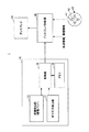
図1は、本発明の一実施例(実施例1)による車両用操作装置1の要部構成を示すシステム図である。図2は、タッチパッド10を概略的に示す上面図である。図3は、タッチパッド10の要部断面を概略的に示す断面図である。尚、図2には、タッチパッド10を操作する手が概略的に示されているが、図3には示されない。図4は、ディスプレイ20上に表示される操作メニューの一例を示す図である。
FIG. 1 is a system diagram showing a main configuration of a
車両用操作装置1は、タッチパッド10と、ディスプレイ制御部30と、ディスプレイ20とを含む。
The
タッチパッド10は、車室内の適切な場所に設けられる。タッチパッド10は、好ましくは、運転者が操作しやすい位置(運転姿勢を保ちながら手を伸ばして届く位置)に配置される。タッチパッド10は、例えばコンソールボックス又はその周辺に配置されてもよい。タッチパッド10は、座標検出部12と、押下圧力検出部14と、制御部16と、メモリ18とを含む。
The
座標検出部12は、図2に示すように、2次元の略平らなタッチ操作面を備える。座標検出部12は、静電センサを備え、その検出信号が制御部16に送られる。座標検出部12は、例えば、静電パッドにより構成される。静電パッドは、例えば、平面上にX方向、Y方向のそれぞれに絶縁体を挟んで電極(静電センサ)が直線状に延在する構造を有する。これらの電極に、絶縁体のパネルを挟んで人の指が接近すると、電極と指を極板とするコンデンサが形成され、電極の電荷量(及びそれの伴い静電容量)が変化する。この場合、電極の検出信号(電極に溜められる電荷の変化量を表す信号)が制御部16に送られてよい。
As shown in FIG. 2, the
押下圧力検出部14は、タッチパッド10(典型的には、座標検出部12を構成する静電パッド)に付与される圧力又は荷重を検出する。即ち、押下圧力検出部14は、タッチパッド10上での押下操作(決定操作)を検出する。押下圧力検出部14は、例えば感圧センサにより構成される。押下圧力検出部14は、座標検出部12の操作面に付与される押下方向の荷重が伝達される箇所であれば任意の場所に配置されてもよい。例えば、図3に示す例では、押下圧力検出部14を構成する感圧センサは、座標検出部12の中央部の下方に設置されているが、座標検出部12を支持する部材の下面70等に配置されてもよい。また、押下圧力検出部14を構成する感圧センサは、複数個分散した位置に設けられてもよい。
The pressing
制御部16及びメモリ18は、例えばマイクロコンピューターにより構成される。
The
制御部16は、座標検出部12からの出力(検出信号)に基づいて、操作面内の座標位置を表す座標信号、即ち操作者によりタッチ操作された座標位置(操作指の位置)を表す座標信号を生成する。尚、座標検出部12が静電パッドで構成される場合、上述の如く電極と操作指からなるコンデンサには電荷が蓄えられ、各電極における電荷の変化量が操作指の位置に応じて異なるため、各電極からの検出信号に基づいて、操作指の位置を特定することができる。具体的には、制御部16は、座標検出部12からの出力が所定の基準値を超えた場合に、座標検出部12からの出力の最大位置に基づいて座標信号を生成する。所定の基準値は、例えば電極に溜まる電荷の変化量に関連する値である。例えば、制御部16は、電極に溜まる電荷の変化量(最大の電荷変化量)が基準値を超えた場合に、操作者により選択操作がされていると判断して、座標信号(例えば電荷の変化量が最大となる2次元位置を表す座標信号)を生成し、電極に溜まる電荷の変化量が基準値を超えない場合に、操作者により選択操作がされていないと判断して、座標信号を生成しない。尚、基準値は、メモリ18に記憶されてもよい。生成した座標信号は、ディスプレイ制御部30に送信される。
Based on the output (detection signal) from the coordinate
制御部16は、押下圧力検出部14からの出力(圧力又は荷重を表す検出信号)に基づいて、決定信号を生成する。例えば、押下圧力検出部14からの出力(押下圧力)が所定閾値Pn(以下、「第1閾値Pn」という)を越えた場合に、操作者による決定操作を検出して、決定信号を生成する。生成した決定信号は、ディスプレイ制御部30に送信される。尚、押下圧力検出部14を構成する感圧センサが複数個設けられる場合、制御部16は、いずれかの感圧センサからの出力が第1閾値Pnを越えた場合に、決定信号を生成してもよい。この場合、感圧センサは、タッチパッド10(典型的には、座標検出部12を構成する静電パッド)上での押下位置を検出する目的で複数設けられるのではなく、タッチパッド10上での押下操作があったか否かだけを検出する目的で設けられてよい。従って、決定信号は、決定操作を検出したことだけを表す信号であり、押下操作の位置のような他の情報を含まない信号であってよい。
The
制御部16は、ディスプレイ制御部30との間で通信し、各種情報(座標信号や決定信号、メッセージ出力要求等)をディスプレイ制御部30に送信する。尚、制御部16の機能の一部又は全部は、座標検出部12により実現されてもよい。
The
ディスプレイ20は、液晶ディスプレイやHUD(ヘッドアップディスプレイ)のような任意の表示装置であってよい。ディスプレイ20は、車室内の適切な位置(例えば、インストルメントパネル)に配置される。ディスプレイ20は、タッチパネルディスプレイであってもよいし、タッチ操作ができないタイプのディスプレイであってもよい。ディスプレイ20には、タッチパッド10で操作可能な操作内容を表す操作メニュー(図4参照)が表示される。尚、操作メニューの背景には又は操作メニューが表示されないときには、ディスプレイ20には、地図表示、TV、周辺監視カメラの映像等が表示されてもよい。
The
操作メニューは、図4に示すように画面全体に表示されてもよいし、画面の一部に表示されてもよい。操作メニューは、図4に示すように、タッチパッド10で操作可能な2つ以上の操作項目を含む。操作メニューは、他の情報表示部(例えば、TV、オーディオ、外気温、燃費などの走行情報、エンターテイメント情報等を表示する部位)を含んでもよい。
The operation menu may be displayed on the entire screen as shown in FIG. 4 or may be displayed on a part of the screen. As shown in FIG. 4, the operation menu includes two or more operation items that can be operated with the
操作項目は、仮想的な操作ボタンを構成する。操作項目(操作ボタン)は、任意の種類(機能)に関するものであってよい。即ち、タッチパッド10で操作可能な内容は、任意であってよい。例えば、操作項目は、ナビゲーション装置の各種設定を行うための画面(メニュー画面)や地図画面(例えば現在地表示画面)をディスプレイ20上に表示させる(呼び出す)ための操作項目を含んでよい。また、操作項目は、空調装置の各種設定を行うための操作項目や、その画面をディスプレイ20上に表示させるための操作項目を含んでよい。また、操作項目は、オーディオやTVの各種設定(音量調整等)を行うための操作項目や、その画面をディスプレイ20上に表示させるための操作項目を含んでよい。また、操作項目は、任意のアプリケーションを起動するための操作項目(アイコン、ランチャ)であってもよい。図4に示す例では、操作メニューは、タッチパッド10でエアコンの各種設定を行うためのものである。
The operation items constitute virtual operation buttons. The operation item (operation button) may relate to an arbitrary type (function). That is, the content that can be operated with the
操作項目は、後述のディスプレイ制御部30による制御下で、タッチパッド10からの座標信号に基づいて、通常の表示から選択表示へと変更されたり、選択表示から通常の表示へと変更されたりする。図4に示す例では、ディスプレイ20上には、タッチパッド10上の操作で移動させることができるポインタ80が示される。ポインタ80は、例えばブロア風量の“LO”を選択している状態であり、従って、操作項目“LO”が選択表示とされている。尚、ポインタ80の移動態様は、タッチパッド10からの座標信号(例えば指移動時の座標信号の変化を含む)に基づくものであれば、任意であってよい。例えば、ポインタ80の位置は、座標信号の座標と一対一で対応してもよいし、或いは、通常のノートPC等のように、ポインタ80の移動先の位置が、座標信号の変化態様(指の移動態様)により定まる態様であってもよい。即ちディスプレイ20の画面の座標系がタッチパッド10の操作面の座標系と絶対的に対応する絶対的な同期態様であってもよいし、或いは、ディスプレイ20の画面の座標系がタッチパッド10の操作面の座標系と相対的に対応する相対的な同期態様であってもよい。また、ポインタ80は必ずしも必要でなく、単に、選択表示とされる操作項目が、タッチパッド10からの座標信号に基づいて、変化するものであってもよい。また、この際、座標信号の座標に近い操作項目に対して、引き込み力が作用するような態様で、選択表示とされる操作項目が決定されてもよい。
The operation item is changed from the normal display to the selection display or from the selection display to the normal display based on the coordinate signal from the
ディスプレイ制御部30は、例えばマイクロコンピューターにより構成され、ECUとして具現化されてもよい。尚、ディスプレイ制御部30とタッチパッド10との接続態様は、任意であり、有線、無線またはその組み合わせであってもよいし、直接的な接続や間接的な接続であってもよい。また、ディスプレイ制御部30の機能の一部又は全部は、タッチパッド10の制御部16やディスプレイ20内の制御部(図示せず)により実現されてもよいし、逆にタッチパッド10の制御部16の機能の一部又は全部がディスプレイ制御部30により実現されてもよい。
The
ディスプレイ制御部30には、車速を表す車速情報や、車両の電源の状態(IG,ACC)に関する電源情報が入力される。
The
ディスプレイ制御部30には、任意的な構成として、メカニカルスイッチ40が接続される。メカニカルスイッチ40は、選択スイッチ41と、決定スイッチ42とを含む。図示の例では、選択スイッチ41は、上下左右を指示する各スイッチを含む。尚、メカニカルスイッチ40は、例えばステアリングホイールに設けられるステアリングスイッチであってもよい。
A
ディスプレイ制御部30は、主なる機能として、ディスプレイ20とタッチパッド10とを同期させて、タッチパッド10での操作を補助する。具体的には、ディスプレイ制御部30は、ディスプレイ20において操作メニュー(図4参照)を表示すると共に、タッチパッド10からの信号(座標信号や決定信号)に基づいて、各種操作項目の選択・決定処理を行う。即ち、ディスプレイ制御部30は、上述の如く、タッチパッド10からの座標信号に基づいて、操作メニューのいずれか1つの操作項目を選択表示とする(即ち“選択操作”に応答する)。尚、初期状態では、任意の1つの操作項目がデフォルトで選択表示とされてもよいし、いずれの操作項目も非選択表示とされてもよい。尚、選択表示は、その操作項目が選択されていることを操作者が分かるような表示であれば任意であり、例えば、選択表示とすべき操作項目の表示の輝度や色などを他の操作項目と異ならすことで実現されてもよいし、操作項目の外枠が強調表示されてもよい(図6参照)。また、ディスプレイ制御部30は、タッチパッド10からの決定信号に基づいて、その際に選択表示とされている操作項目の操作内容を実現する(即ち“決定操作”に応答する)。尚、この操作内容は、操作項目に依存するが、操作メニューの変更等のような画面の遷移や、アプリケーションの起動、操作対象装置(例えば空調装置)への制御信号の送信等を伴うものであってよい。また、決定操作検出時に、“決定操作”が検出されたことをユーザに伝達するために、決定された操作項目の表示を適切に変化させてもよい。
The
本実施例のタッチパッド10によれば、操作者は、ディスプレイ20を見ながら、座標検出部12の操作面に操作指(例えば人差し指)で触れながら操作面内で操作指を動かすことで選択操作を行い、所望の操作項目を選択することができる。そして、所望の操作項目が選択表示となったときに、その場所で操作指により座標検出部12を押下することで、決定操作を行うことができる。即ち、所望の選択がなされた接触位置で座標検出部12を押下することで、決定操作を行うことができる。
According to the
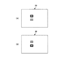
図5は、選択操作の際の指の接触状態と、決定操作の際の指の接触状態とを対比して模式的に示す図であり、(A)は、選択操作の際の指の接触状態を示し、(B)は、決定操作の際の指の接触状態を示す。図5では、図2のA−A断面に沿った断面図でタッチパッド10が示されている。図6は、決定操作を行う際に操作項目の選択状態が変化する態様を模式的に示す図であり、ディスプレイ20の画面を模式的に示す図である。尚、図6では、図4と異なり、簡易的に、操作項目は、単なる四角の外形だけで2つだけ示されている。また、図6では、選択表示は、選択された操作項目の外枠が強調表示されることで、実現されている。
FIG. 5 is a diagram schematically showing a finger contact state during the selection operation and a finger contact state during the determination operation. FIG. 5 (A) is a diagram illustrating a finger contact during the selection operation. A state is shown, (B) shows the contact state of the finger in determination operation. 5, the
選択操作の際は、図5(A)に示すように、操作者は、指先でタッチパッド10の座標検出部12に触れる。これは、一般的な傾向ではあるが、指先の方が接触面積が小さく、緻密な位置指定が容易であるためである。他方、決定操作の際は、図5(A)に示すように、操作者は、指の腹の部分でタッチパッド10の座標検出部12に下方に押す。これは、押下操作を行う際は、座標検出部12に下方に押す力Fが必要となるが、かかる力Fを加えようとすると、指の腹の部分が座標検出部12に当たるためである。このため、操作者が、所望の操作項目が選択表示となったときに(図6(A)参照)、その場所で操作指により座標検出部12を押下して、決定操作を行うと、この決定操作の際に、図5(A)及び図5(B)に示すように、指の接触点の座標がずれてしまい(ずれ量Δ参照)、選択していた操作項目が変化してしまう場合がある(図6(B)参照)。即ち、決定操作の際に座標信号がずれ量Δ分だけ変化し、これに伴って、選択していた操作項目が変化してしまう場合がある。
In the selection operation, as shown in FIG. 5A, the operator touches the coordinate
そこで、本実施例の制御部16は、かかる決定操作に伴って生じる座標信号の変化に対して、操作項目の選択の変更を抑制する選択項目変更抑制処理を行う。以下、この選択項目変更抑制処理について説明する。
Therefore, the
図7は、本実施例の制御部16により実行されてよい選択項目変更抑制処理の一例を示すフローチャートである。図7に示す処理ルーチンは、例えばイグニッションスイッチがオン状態であるときに、所定周期毎に実行されてもよい。
FIG. 7 is a flowchart illustrating an example of the selection item change suppression process that may be executed by the
ステップ700では、座標信号が生成されるか否か(選択操作中か否か)が判定される。即ち、座標検出部12から基準値以上の出力があったか否かが判定される。ステップ700において座標信号が生成された場合には、ステップ702に進み、それ以外の場合、即ち座標信号が生成されない場合(選択操作が検出されない場合)には、選択操作の待ち状態となる。
In step 700, it is determined whether or not a coordinate signal is generated (whether or not a selection operation is being performed). That is, it is determined whether or not there is an output greater than the reference value from the coordinate
ステップ702では、押下圧力検出部14により検出された押下圧力Pが判断される。押下圧力Pが0の場合、ステップ700に戻り、選択操作の待ち状態となる。この場合、操作が一旦完了したと判断できるためである。尚、選択操作中は、基本的に、押下圧力Pがゼロよりも僅かに大きくなる。
In
押下圧力Pが所定閾値P0(以下、「第2閾値P0」という)を越える場合、ステップ710に進む。第2閾値P0は、決定操作の途中(決定信号が生成されるまでの過程)か否かを判断するための閾値である。第2閾値P0は、0よりも大きいが第1閾値Pnよりも小さい値に設定される。第2閾値P0は、例えば通常的な選択操作で発生しうる押下圧力の最大値よりも大きく設定されてもよく、試験等により適合されてよい。 When the pressing pressure P exceeds a predetermined threshold value P0 (hereinafter referred to as “second threshold value P0”), the process proceeds to step 710. The second threshold value P0 is a threshold value for determining whether or not the determination operation is in progress (the process until the determination signal is generated). The second threshold value P0 is set to a value larger than 0 but smaller than the first threshold value Pn. For example, the second threshold value P0 may be set larger than the maximum value of the pressing pressure that can be generated by a normal selection operation, and may be adapted by a test or the like.
押下圧力Pが第1閾値Pnを越える場合、ステップ704に進む。第1閾値Pnは、上述の如く、決定操作が検出される閾値であり、上述の如く、第2閾値P0よりも大きい。従って、押下圧力Pが第2閾値P0よりも大きいが第1閾値Pnを越えない間は、ステップ710に進むことになり、押下圧力Pがゼロよりも大きいが第2閾値P0を越えない間は、ステップ708に進むことになる。 When the pressing pressure P exceeds the first threshold value Pn, the process proceeds to step 704. As described above, the first threshold Pn is a threshold at which a determination operation is detected, and is larger than the second threshold P0 as described above. Accordingly, while the pressing pressure P is greater than the second threshold value P0 but does not exceed the first threshold value Pn, the process proceeds to step 710, and while the pressing pressure P is greater than zero but does not exceed the second threshold value P0. The process proceeds to step 708.
ステップ704では、決定操作が検出され、決定信号が生成される。決定信号は、上述の如く、ディスプレイ制御部30に送信される。ディスプレイ制御部30は、上述の如く、決定信号を受信すると、その時点で選択表示されている(選択されている)操作項目の操作内容を実現する(即ち“決定操作”に応答する)。尚、決定操作の検出時は、後述の決定操作の途中と同様、座標信号(座標位置)の更新がキャンセルされてよい。
In step 704, a decision operation is detected and a decision signal is generated. The determination signal is transmitted to the
ステップ708では、選択操作中であると判断して、座標信号(座標位置)の更新が実行される。例えば、座標検出部12からの最新の出力に基づいて、新たな座標信号が生成される。この場合、新たな座標信号がディスプレイ制御部30に送信される。ディスプレイ制御部30は、受信した座標信号に基づいて、必要に応じて操作項目の選択を変更する。ステップ708の処理が終了すると、ステップ702に戻る。
In
ステップ710では、決定操作の途中であると判断して、座標信号(座標位置)の更新がキャンセルされる。例えば、座標検出部12からの最新の出力に基づく新たな座標信号が生成されない。この場合、現時点で保持する最新の座標信号(即ち、更新されない座標信号)がディスプレイ制御部30に送信されてよい。従って、ディスプレイ制御部30においては、座標信号が変化しないので、操作項目の選択が変更されることはない。或いは、座標検出部12からの最新の出力に基づいて、新たな座標信号が生成されるが、生成した新たな座標信号が、ディスプレイ制御部30に送信されないようにしてもよい。いずれにしても、決定操作の途中と判断された場合には、座標信号の更新がキャンセルされるので、図5及び図6を参照して説明した問題点(即ち、決定操作の際に、指の接触点の座標がずれてしまい、選択していた操作項目が変化しうるという問題点)を防止することができる。ステップ710の処理が終了すると、ステップ702に戻る。この場合、例えば次の処理周期で、押下圧力Pが第1閾値Pnを越えた場合には、決定信号が生成され、決定操作の途中に変更されずに選択されていた操作項目の機能が実現される。
In
図7に示す処理によれば、押下圧力Pが選択操作中よりも大きいが決定操作が検出されるほど大きくなっていない場合に、決定操作の途中であると判断して、座標信号(座標位置)の更新がキャンセルされる。これにより、決定操作の際に、指の接触点の座標がずれてしまい、選択していた操作項目が変化しうることを適切に防止することができる。尚、決定操作の途中は、押下圧力Pは、押下開始時(決定操作開始時)から決定操作検出時まで増加傾向を示す。従って、押下圧力Pが選択操作中よりも大きいが決定操作が検出されるほど大きくなっておらず、且つ、押下圧力Pが増加傾向である場合に、決定操作の途中であると判断して、座標信号(座標位置)の更新をキャンセルすることとしてもよい。この場合、押下圧力Pが増加傾向でない場合には、ステップ708に進み、座標信号(座標位置)の更新が実行される。 According to the processing shown in FIG. 7, when the pressing pressure P is larger than that during the selection operation but not so high that the determination operation is detected, it is determined that the determination operation is in progress, and the coordinate signal (coordinate position) ) Update is canceled. Thereby, it can prevent appropriately that the coordinate of the contact point of a finger | toe will shift | deviate in the case of determination operation, and the selected operation item may change. In the middle of the determination operation, the pressing pressure P tends to increase from the start of pressing (at the start of determination operation) until the determination operation is detected. Therefore, when the pressing pressure P is larger than that during the selection operation but is not so large that the determination operation is detected, and the pressing pressure P tends to increase, it is determined that the determination operation is in progress. The update of the coordinate signal (coordinate position) may be canceled. In this case, if the pressing pressure P does not tend to increase, the process proceeds to step 708 to update the coordinate signal (coordinate position).
図8は、本実施例の制御部16により実行されてよい選択項目変更抑制処理の他の一例を示すフローチャートである。図9は、座標検出部12の操作面における2次元座標軸の定義例を示す図である。図9には、タッチパッド10の座標検出部12が上面視で示されている。ここでは、前提として、図9に示すように、座標検出部12の操作面(タッチパッド面)の横方向をx軸とし、縦方向をy軸とし、左手前側を原点とする。尚、y軸の原点側(−側)が操作者側(例えば運転者や助手席の乗員)となる。
FIG. 8 is a flowchart illustrating another example of the selection item change suppression process that may be executed by the
図8に示す処理ルーチンは、例えばイグニッションスイッチがオン状態であるときに、所定周期毎に実行されてもよい。図8に示すステップ800,802,804,808,810の処理は、それぞれ、図7に示したステップ700,702,704,708,710と同一であってよく、説明を省略する。
The processing routine shown in FIG. 8 may be executed at predetermined intervals when, for example, the ignition switch is on. The processing in
ステップ802において、押下圧力Pが第2閾値P0を越える場合、ステップ806に進む。
In
ステップ806では、座標検出部12からの最新の出力に基づいて、指の接触点の座標位置の変化方向が判断される。例えば、座標検出部12からの最新の出力に基づいて、今回周期の指の接触点の座標位置(x(i)、y(i))が算出され、この座標位置(x(i)、y(i))が、押圧開始時の周期の座標位置(x(k)、y(k))と比較される。押圧開始時の周期は、押下圧力Pが最初に第2閾値P0を超えた周期である。このとき、y方向の変化がマイナスである場合(即ちy(i)−y(k)<0の場合)、ステップ810に進む。これは、図5及び図6を参照して説明したように、決定操作の際に生じうる指の接触点の座標のずれ方向は、指先から指の腹の部分に向かう方向、即ち操作者側に向かう方向であるためである。他方、y方向の変化が0以上である場合は、ステップ808に進む。
In step 806, based on the latest output from the coordinate
尚、本ステップ806では、今回周期の指の接触点の座標位置と、押圧開始時の周期の座標位置との関係に基づいて、指の接触点の座標位置の変化方向が判断されている。これは、指先から指の腹の部分までの距離はそもそも短いので、できるだけ変化量が大きい2時点間で変化方向を判断するのが精度の観点から有利であるためである。しかしながら、押下圧力Pが第2閾値P0を超えている間の任意の2時点での座標位置を比較してもよい。 In step 806, the change direction of the coordinate position of the finger contact point is determined based on the relationship between the coordinate position of the finger contact point in the current cycle and the coordinate position of the cycle at the start of pressing. This is because the distance from the fingertip to the abdomen of the finger is short in the first place, and it is advantageous from the viewpoint of accuracy to determine the change direction between two time points where the change amount is as large as possible. However, the coordinate positions at any two points in time while the pressing pressure P exceeds the second threshold value P0 may be compared.
このように図8に示す処理によれば、決定操作の際に生じうる指の接触点の座標のずれ方向を考慮するので、決定操作の際に生じる座標位置の変化(操作者の意図しない座標位置の変化)と、その他の要因で起こりうる座標位置の変化(例えば、比較的大きい接触力で行なわれる選択操作中の座標位置の変化)と、を精度良く判別することができる。これにより、決定操作の際に、指の接触点の座標がずれてしまい、選択していた操作項目が変化しうることを精度良く防止することができる。 As described above, according to the processing shown in FIG. 8, since the shift direction of the coordinates of the finger contact point that may occur during the determination operation is taken into account, the change in the coordinate position that occurs during the determination operation (coordinates that are not intended by the operator) It is possible to accurately discriminate between a change in position) and a change in coordinate position that may occur due to other factors (for example, a change in coordinate position during a selection operation performed with a relatively large contact force). Accordingly, it is possible to accurately prevent the coordinate of the contact point of the finger from being shifted during the determination operation and the selected operation item can be changed.
図10は、本実施例の制御部16により実行されてよい選択項目変更抑制処理の他の一例を示すフローチャートである。図8に示すステップ1000,1002,1004,1006,1008,1010の処理は、それぞれ、図8に示したステップ800,802,804,806,808,810と同一であってよく、説明を省略する。
FIG. 10 is a flowchart illustrating another example of the selection item change suppression process that may be executed by the
ステップ1006において、指の接触点の座標位置の変化方向がy軸のマイナス方向である場合、ステップ1009に進み、指の接触点の座標位置の変化方向がy軸のプラス方向である場合は、ステップ1008に進む。 In step 1006, when the change direction of the coordinate position of the finger contact point is the negative direction of the y axis, the process proceeds to step 1009, and when the change direction of the coordinate position of the finger contact point is the positive direction of the y axis, Proceed to step 1008.
ステップ1009では、指の接触点の座標位置の変化量が所定量より大きいか否かが判定される。所定量は、決定操作の際に生じうる指の接触点の座標のずれ量の取りうる範囲の最大値に対応してもよい。これは、操作者の指の長さにも依存するが、指先から指の腹の部分までの距離は、絶対的に小さく、個人差はさほど大きくないので、平均値などが使用されてもよい。指の接触点の座標位置の変化量は、今回周期の指の接触点の座標位置(x(i)、y(i))と、押圧開始時の周期の座標位置(x(k)、y(k))との間の距離として算出されてよい。指の接触点の座標位置の変化量が所定量より大きい場合は、ステップ1008に進む。これは、決定操作の際に生じうる指の接触点の座標のずれに起因した座標位置の変化で無いと判断できるためである。他方、指の接触点の座標位置の変化量が所定量以下である場合は、ステップ1009に進む。 In step 1009, it is determined whether or not the amount of change in the coordinate position of the finger contact point is greater than a predetermined amount. The predetermined amount may correspond to the maximum value of a possible range of the deviation amount of the coordinates of the finger contact point that may occur during the determination operation. This depends on the length of the operator's finger, but the distance from the fingertip to the abdomen of the finger is absolutely small and the individual difference is not so large, so an average value or the like may be used. . The amount of change in the coordinate position of the finger contact point is the coordinate position (x (i), y (i)) of the finger contact point in the current cycle and the coordinate position (x (k), y of the cycle at the start of pressing). (K)) may be calculated. If the change amount of the coordinate position of the finger contact point is larger than the predetermined amount, the process proceeds to step 1008. This is because it can be determined that the coordinate position is not changed due to a shift in the coordinates of the contact point of the finger that may occur during the determination operation. On the other hand, if the change amount of the coordinate position of the contact point of the finger is equal to or less than the predetermined amount, the process proceeds to step 1009.
このように図10に示す処理によれば、決定操作の際に生じうる指の接触点の座標のずれ量を考慮するので、決定操作の際に生じる座標位置の変化(操作者の意図しない座標位置の変化)と、その他の要因で起こりうる座標位置の変化と、を精度良く判別することができる。これにより、決定操作の際に、指の接触点の座標がずれてしまい、選択していた操作項目が変化しうることを精度良く防止することができる。 As described above, according to the processing shown in FIG. 10, since the shift amount of the coordinates of the finger contact point that may occur during the determination operation is taken into account, the change in the coordinate position that occurs during the determination operation (coordinates that are not intended by the operator) It is possible to accurately discriminate between a change in position) and a change in coordinate position that may occur due to other factors. Accordingly, it is possible to accurately prevent the coordinate of the contact point of the finger from being shifted during the determination operation and the selected operation item can be changed.
尚、図10に示す処理は、精度を高める観点から、座標位置の変化量と共に、座標位置の変化方向が判断されているが、座標位置の変化方向の判断(ステップ1006の判定)は省略されてもよい。 In the process shown in FIG. 10, the change direction of the coordinate position is determined together with the change amount of the coordinate position from the viewpoint of improving accuracy, but the determination of the change direction of the coordinate position (determination in step 1006) is omitted. May be.
図11は、本発明の一実施例(実施例2)による車両用操作装置2の要部構成を示すシステム図である。本実施例2の車両用操作装置2は、操作者判別装置50を備える点が主に、上述した実施例1の車両用操作装置1と異なる。
FIG. 11 is a system diagram showing the main configuration of the
操作者判別装置50は、タッチパッド10の操作者が運転者か又は助手席側の乗員か否かを判別する。この判別方法は、多種多様であり、任意の適切な方法が使用されてもよい。例えば、操作者判別装置50は、例えば車室内カメラからの画像の画像認識結果に基づいて、操作者を判別してもよいし、タッチパッド10の左右方向両側に設けられる近接センサの出力の有無に基づいて、操作者を判別してもよい。また、ステアリングホイールに設けられるタッチセンサに基づいて運転者の手の状態(ステアリングホイールからの手の離れ)を検出し、この検出結果に基づいて、操作者を判別してもよい。操作者判別装置50による操作者の判別結果は、タッチパッド10の制御部16に送信される。尚、操作者判別装置50は、ディスプレイ制御部30を介してタッチパッド10の制御部16に接続されてもよく、この場合、操作者判別装置50による操作者の判別結果は、ディスプレイ制御部30を介してタッチパッド10の制御部16に送信される。
The
図12は、本実施例2の制御部16により実行されてよい選択項目変更抑制処理の他の一例を示すフローチャートである。図13は、操作者が助手席側乗員である場合の指のずれ方向の説明図である。尚、ここでは、前提として、図9に示したように、座標検出部12の操作面(タッチパッド面)の横方向をx軸とし、縦方向をy軸とし、左手前側を原点とする。尚、y軸の原点側が操作者側(例えば運転者や助手席の乗員)となる。右ハンドル車でタッチパッド10がコンソールボックスに配置される場合、x軸の+方向が運転者側となる。
FIG. 12 is a flowchart illustrating another example of the selection item change suppression process that may be executed by the
図12に示す処理ルーチンは、例えばイグニッションスイッチがオン状態であるときに、所定周期毎に実行されてもよい。図12に示すステップ1200,1202,1204,1208,1210の処理は、それぞれ、図7に示したステップ700,702,704,708,710と同一であってよく、説明を省略する。
The processing routine shown in FIG. 12 may be executed at predetermined intervals, for example, when the ignition switch is on. The processes in steps 1200, 1202, 1204, 1208, and 1210 shown in FIG. 12 may be the same as
ステップ1201では、操作者判別装置50から操作者の判別結果が受信される。ステップ1202において、押下圧力Pが第2閾値P0を越える場合、ステップ1206に進む。
In
ステップ1206では、座標検出部12からの最新の出力に基づいて、指の接触点の座標位置の変化方向が、操作者に向かう方向であるか否かが判定される。指の接触点の座標位置の変化方向は、図8のステップ806で説明した場合と同様、押圧開始時の周期の座標位置(x(k)、y(k))から、今回周期の指の接触点の座標位置(x(i)、y(i))までのベクトル(x(i)−x(k)、y(i)−y(k))として算出されてもよい。指の接触点の座標位置の変化方向が、操作者に向かう方向であるか否かは、上記ステップ1201で得られた操作者の判別結果に基づいて判定される。具体的には、右ハンドル車でタッチパッド10がコンソールボックスに配置される場合を想定すると、操作者が運転者であると判定された場合には、x方向の変化がプラスであり且つy方向の変化がマイナスである場合(即ちx(i)−x(k)>0、且つ、y(i)−y(k)<0である場合)、指の接触点の座標位置の変化方向が、操作者に向かう方向であると判定されてもよい。また、操作者が助手席乗員であると判定された場合には、x方向の変化がマイナスであり且つy方向の変化がマイナスである場合(即ちx(i)−x(k)<0、且つ、y(i)−y(k)<0である場合)、指の接触点の座標位置の変化方向が、操作者に向かう方向であると判定されてもよい。
In step 1206, based on the latest output from the coordinate
本ステップ1206において、指の接触点の座標位置の変化方向が、操作者に向かう方向である場合には、ステップ1210に進み、指の接触点の座標位置の変化方向が、操作者に向かう方向でない場合には、ステップ1208に進む。これは、決定操作の際に生じうる指の接触点の座標のずれ方向は、指先から指の腹の部分に向かう方向であり、これは操作者に向かう方向(より正確には指の延在する方向に沿った操作者に向かう方向)に対応するためである。そして、例えば操作者が助手席側乗員である場合、図13(A)に示すように、操作者に向かう方向は、x軸及びy軸とも負の方向であるためである。他方、図13(B)に示すように、指の接触点の座標位置の変化方向が、例えば操作者側から離れる方向である場合(x軸及びy軸とも正の方向である場合)、決定操作の際に生じうる指の接触点の座標のずれではないと判断される(この場合、ステップ1208に進む)。 In this step 1206, when the change direction of the coordinate position of the finger contact point is the direction toward the operator, the process proceeds to step 1210, and the change direction of the coordinate position of the finger contact point is the direction toward the operator. If not, go to Step 1208. This is because the direction of deviation of the coordinates of the finger contact point that can occur during the determination operation is the direction from the fingertip toward the belly of the finger, which is the direction toward the operator (more precisely, the extension of the finger). This is because it corresponds to the direction toward the operator along the direction to perform. For example, when the operator is a passenger on the passenger seat side, as shown in FIG. 13A, the direction toward the operator is a negative direction for both the x-axis and the y-axis. On the other hand, as shown in FIG. 13B, when the change direction of the coordinate position of the contact point of the finger is, for example, a direction away from the operator side (when both the x-axis and the y-axis are positive directions), the determination is made. It is determined that there is no deviation in the coordinates of the finger contact point that may occur during the operation (in this case, the process proceeds to step 1208).
尚、本ステップ1206では、今回周期の指の接触点の座標位置と、押圧開始時の周期の座標位置との関係に基づいて、指の接触点の座標位置の変化方向が判断されている。これは、指先から指の腹の部分までの距離はそもそも短いので、できるだけ変化量が大きい2時点間で変化方向を判断するのが精度の観点から有利であるためである。しかしながら、押下圧力Pが第2閾値P0を超えている間の任意の2時点での座標位置を比較してもよい。 In this step 1206, the change direction of the coordinate position of the finger contact point is determined based on the relationship between the coordinate position of the finger contact point in the current cycle and the coordinate position of the cycle at the start of pressing. This is because the distance from the fingertip to the abdomen of the finger is short in the first place, and it is advantageous from the viewpoint of accuracy to determine the change direction between two time points where the change amount is as large as possible. However, the coordinate positions at any two points in time while the pressing pressure P exceeds the second threshold value P0 may be compared.
このように図12に示す処理によれば、決定操作の際に生じうる指の接触点の座標のずれ方向を操作者の位置(操作者の手が差し出される方向)との関係で考慮するので、決定操作の際に生じる座標位置の変化(操作者の意図しない座標位置の変化)と、その他の要因で起こりうる座標位置の変化と、を精度良く判別することができる。これにより、決定操作の際に、指の接触点の座標がずれてしまい、選択していた操作項目が変化しうることを精度良く防止することができる。 As described above, according to the processing shown in FIG. 12, the shift direction of the coordinate of the finger contact point that may occur during the determination operation is considered in relation to the position of the operator (direction in which the operator's hand is presented). Therefore, it is possible to accurately discriminate between a change in coordinate position that occurs during the determination operation (a change in coordinate position that is not intended by the operator) and a change in coordinate position that may occur due to other factors. Accordingly, it is possible to accurately prevent the coordinate of the contact point of the finger from being shifted during the determination operation and the selected operation item can be changed.
尚、図12に示すステップ1206の処理は、図10に示したステップ1006の処理として採用されてもよい。即ち、図12に示す処理においても、指の接触点の座標位置の変化量が考慮されてもよい。 Note that the process of step 1206 shown in FIG. 12 may be adopted as the process of step 1006 shown in FIG. That is, also in the process shown in FIG. 12, the amount of change in the coordinate position of the finger contact point may be taken into consideration.
ここで、上述した実施例1,2は、操作項目が密に配置されている場合(特にy軸方向に対応した方向で密に配置されている場合)に好適である。これは、図5及び図6を参照して説明した問題点(即ち、決定操作の際に、指の接触点の座標がずれてしまい、選択していた操作項目が変化しうるという問題点)は、操作項目が密に配置されている場合に発生しやすいためである。この点、例えば、タッチパッド10の操作面において、指先から指の腹の部分までの距離未満の間隔が、操作項目間の間隔に対応する場合に好適である。この場合、例えばタッチパッド10の操作面における5mm〜10mmの間隔が、選択される隣接する操作項目間の間隔に対応してもよい。
Here, the above-described first and second embodiments are suitable when the operation items are densely arranged (particularly when the operation items are densely arranged in a direction corresponding to the y-axis direction). This is the problem described with reference to FIG. 5 and FIG. 6 (that is, the problem that the coordinate of the finger contact point is shifted during the determination operation, and the selected operation item can be changed). This is because it is likely to occur when operation items are densely arranged. In this regard, for example, on the operation surface of the
尚、上述した実施例においては、特許請求の範囲における「制御装置」は、制御部16及びディスプレイ制御部30により協動して実現されている。尚、上述の如く、制御部16及びディスプレイ制御部30の機能の分担は任意であり、一方の機能の一部又は全部が他方により実現されてもよい。一方の機能の全部が他方により実現される場合、当然ながら両者間の通信は不要となる。また、制御部16及びディスプレイ制御部30の機能は、3つ以上の制御部により協動して実現されてもよい。
In the above-described embodiment, the “control device” in the claims is realized by the cooperation of the
以上、本発明の好ましい実施例について詳説したが、本発明は、上述した実施例に制限されることはなく、本発明の範囲を逸脱することなく、上述した実施例に種々の変形及び置換を加えることができる。 The preferred embodiments of the present invention have been described in detail above. However, the present invention is not limited to the above-described embodiments, and various modifications and substitutions can be made to the above-described embodiments without departing from the scope of the present invention. Can be added.
例えば、感圧センサに代えて、他の荷重センサが押下圧力検出部14として使用されてもよい。
For example, instead of the pressure sensor, another load sensor may be used as the pressing
1、2 車両用操作装置
10 タッチパッド
12 座標検出部
14 押下圧力検出部
16 制御部
18 メモリ
20 ディスプレイ
30 ディスプレイ制御部
40 メカニカルスイッチ
41 選択スイッチ
42 決定スイッチ
50 操作者判別装置
80 ポインタ
DESCRIPTION OF
Claims (4)
前記タッチ操作部に設けられる静電センサと、
前記タッチ操作部に設けられ、前記タッチ操作部に付与される圧力又は荷重を検出する押下圧力検出手段と、
制御装置とを備え、
前記制御装置は、
前記静電センサの出力に基づいて、前記操作面内における指の接触点の二次元座標を検出する接触点座標検出手段と、
前記接触点座標検出手段により検出される二次元座標に基づいて、複数の操作項目のうちの1つの操作項目を選択する操作項目選択手段と、
前記押下圧力検出手段の出力が所定の第1閾値を超えた場合に、選択された操作項目の決定操作を検出する決定操作検出手段とを備え、
前記操作項目選択手段は、前記押下圧力検出手段の出力がゼロより大きい所定の第2閾値を超えるが前記第1閾値を超えない間、前記接触点座標検出手段により検出される二次元座標の変化方向が所定方向である場合、前記接触点座標検出手段の検出結果の変化に対して、操作項目の選択の変更を抑制することを特徴とする、車両用操作装置。 A touch operation unit having a two-dimensional operation surface;
An electrostatic sensor provided in the touch operation unit;
A pressing pressure detecting means provided in the touch operation unit for detecting a pressure or a load applied to the touch operation unit;
A control device,
The controller is
Contact point coordinate detecting means for detecting a two-dimensional coordinate of a finger contact point in the operation surface based on an output of the electrostatic sensor;
An operation item selection means for selecting one operation item among a plurality of operation items based on the two-dimensional coordinates detected by the contact point coordinate detection means;
Determining operation detecting means for detecting the determining operation of the selected operation item when the output of the pressing pressure detecting means exceeds a predetermined first threshold;
The operation item selection means changes the two-dimensional coordinates detected by the contact point coordinate detection means while the output of the pressing pressure detection means exceeds a predetermined second threshold greater than zero but does not exceed the first threshold. When the direction is a predetermined direction, a change in the selection of an operation item is suppressed with respect to a change in a detection result of the contact point coordinate detection unit.
前記タッチ操作部に設けられる静電センサと、
前記タッチ操作部に設けられ、前記タッチ操作部に付与される圧力又は荷重を検出する押下圧力検出手段と、
制御装置とを備え、
前記制御装置は、
前記静電センサの出力に基づいて、前記操作面内における指の接触点の二次元座標を検出する接触点座標検出手段と、
前記接触点座標検出手段により検出される二次元座標に基づいて、複数の操作項目のうちの1つの操作項目を選択する操作項目選択手段と、
前記押下圧力検出手段の出力が所定の第1閾値を超えた場合に、選択された操作項目の決定操作を検出する決定操作検出手段とを備え、
前記操作項目選択手段は、前記押下圧力検出手段の出力がゼロより大きい所定の第2閾値を超えるが前記第1閾値を超えない間、前記接触点座標検出手段により検出される二次元座標の変化方向が所定方向であり、且つ、前記接触点座標検出手段により検出される二次元座標の変化量が所定値未満である場合、操作項目の選択の変更を抑制する、車両用操作装置。 A touch operation unit having a two-dimensional operation surface;
An electrostatic sensor provided in the touch operation unit;
A pressing pressure detecting means provided in the touch operation unit for detecting a pressure or a load applied to the touch operation unit;
A control device,
The control device includes:
Contact point coordinate detecting means for detecting a two-dimensional coordinate of a finger contact point in the operation surface based on an output of the electrostatic sensor;
An operation item selection means for selecting one operation item among a plurality of operation items based on the two-dimensional coordinates detected by the contact point coordinate detection means;
Determining operation detecting means for detecting the determining operation of the selected operation item when the output of the pressing pressure detecting means exceeds a predetermined first threshold;
The operation item selection means changes the two-dimensional coordinates detected by the contact point coordinate detection means while the output of the pressing pressure detection means exceeds a predetermined second threshold greater than zero but does not exceed the first threshold. direction is the predetermined direction, and, when the variation of the two-dimensional coordinates detected by the touch point coordinate detecting means is less than a predetermined value, to suppress the change of the selection of the operation item, car dual operating device.
Priority Applications (1)
| Application Number | Priority Date | Filing Date | Title |
|---|---|---|---|
| JP2011226876A JP5849597B2 (en) | 2011-10-14 | 2011-10-14 | Vehicle control device |
Applications Claiming Priority (1)
| Application Number | Priority Date | Filing Date | Title |
|---|---|---|---|
| JP2011226876A JP5849597B2 (en) | 2011-10-14 | 2011-10-14 | Vehicle control device |
Publications (3)
| Publication Number | Publication Date |
|---|---|
| JP2013088912A JP2013088912A (en) | 2013-05-13 |
| JP2013088912A5 JP2013088912A5 (en) | 2014-11-27 |
| JP5849597B2 true JP5849597B2 (en) | 2016-01-27 |
Family
ID=48532790
Family Applications (1)
| Application Number | Title | Priority Date | Filing Date |
|---|---|---|---|
| JP2011226876A Active JP5849597B2 (en) | 2011-10-14 | 2011-10-14 | Vehicle control device |
Country Status (1)
| Country | Link |
|---|---|
| JP (1) | JP5849597B2 (en) |
Families Citing this family (4)
| Publication number | Priority date | Publication date | Assignee | Title |
|---|---|---|---|---|
| JP6230119B2 (en) * | 2014-03-17 | 2017-11-15 | アルプス電気株式会社 | Input device |
| WO2019009138A1 (en) * | 2017-07-04 | 2019-01-10 | パイオニア株式会社 | Operation input device |
| JP7225034B2 (en) * | 2019-06-10 | 2023-02-20 | アルパイン株式会社 | Press operation detection device and press operation detection method |
| KR102246818B1 (en) * | 2019-08-20 | 2021-04-30 | 권명미 | Capacitive input device and user input judging method using the same |
Family Cites Families (2)
| Publication number | Priority date | Publication date | Assignee | Title |
|---|---|---|---|---|
| JP2003276525A (en) * | 2002-03-22 | 2003-10-02 | Toyota Motor Corp | Complex switch of touch panel |
| JP4600548B2 (en) * | 2008-08-27 | 2010-12-15 | ソニー株式会社 | REPRODUCTION DEVICE, REPRODUCTION METHOD, AND PROGRAM |
-
2011
- 2011-10-14 JP JP2011226876A patent/JP5849597B2/en active Active
Also Published As
| Publication number | Publication date |
|---|---|
| JP2013088912A (en) | 2013-05-13 |
Similar Documents
| Publication | Publication Date | Title |
|---|---|---|
| JP5644962B2 (en) | Operating device | |
| JP6277786B2 (en) | Vehicle control device | |
| JP5962776B2 (en) | Operating device | |
| JP2013117900A (en) | Operation device for vehicle | |
| US20130097553A1 (en) | Information display device and method for shifting operation of on-screen button | |
| JP2015170282A (en) | Operation device for vehicle | |
| JP6127679B2 (en) | Operating device | |
| JP5849597B2 (en) | Vehicle control device | |
| JP2014211861A (en) | Input device | |
| JP6086146B2 (en) | Vehicle control device | |
| JP2010049460A (en) | Operation input device | |
| JP2018136616A (en) | Display operation system | |
| US11221735B2 (en) | Vehicular control unit | |
| JP5954145B2 (en) | Input device | |
| WO2016001730A1 (en) | Operation device and operation method | |
| JP5985829B2 (en) | Vehicle control device | |
| JP2013033343A (en) | Operation device for vehicle | |
| JP2013084052A (en) | Operation device for vehicle | |
| JP2016099891A (en) | Display operation apparatus | |
| JP2014203177A (en) | Input device | |
| JP2011107900A (en) | Input display device | |
| EP3352067B1 (en) | Vehicular input device and method of controlling vehicular input device | |
| JP2018122827A (en) | On-vehicle information input device and on-vehicle information input system |
Legal Events
| Date | Code | Title | Description |
|---|---|---|---|
| A521 | Written amendment |
Free format text: JAPANESE INTERMEDIATE CODE: A523 Effective date: 20141008 |
|
| A621 | Written request for application examination |
Free format text: JAPANESE INTERMEDIATE CODE: A621 Effective date: 20141008 |
|
| A131 | Notification of reasons for refusal |
Free format text: JAPANESE INTERMEDIATE CODE: A131 Effective date: 20150825 |
|
| A977 | Report on retrieval |
Free format text: JAPANESE INTERMEDIATE CODE: A971007 Effective date: 20150826 |
|
| A521 | Written amendment |
Free format text: JAPANESE INTERMEDIATE CODE: A523 Effective date: 20151009 |
|
| TRDD | Decision of grant or rejection written | ||
| A01 | Written decision to grant a patent or to grant a registration (utility model) |
Free format text: JAPANESE INTERMEDIATE CODE: A01 Effective date: 20151104 |
|
| A61 | First payment of annual fees (during grant procedure) |
Free format text: JAPANESE INTERMEDIATE CODE: A61 Effective date: 20151117 |
|
| R151 | Written notification of patent or utility model registration |
Ref document number: 5849597 Country of ref document: JP Free format text: JAPANESE INTERMEDIATE CODE: R151 |