JP5847656B2 - Brake control device for vehicle - Google Patents
Brake control device for vehicle Download PDFInfo
- Publication number
- JP5847656B2 JP5847656B2 JP2012141957A JP2012141957A JP5847656B2 JP 5847656 B2 JP5847656 B2 JP 5847656B2 JP 2012141957 A JP2012141957 A JP 2012141957A JP 2012141957 A JP2012141957 A JP 2012141957A JP 5847656 B2 JP5847656 B2 JP 5847656B2
- Authority
- JP
- Japan
- Prior art keywords
- valve
- valve opening
- power
- cylinder
- input
- Prior art date
- Legal status (The legal status is an assumption and is not a legal conclusion. Google has not performed a legal analysis and makes no representation as to the accuracy of the status listed.)
- Expired - Fee Related
Links
Images


Classifications
-
- B—PERFORMING OPERATIONS; TRANSPORTING
- B60—VEHICLES IN GENERAL
- B60T—VEHICLE BRAKE CONTROL SYSTEMS OR PARTS THEREOF; BRAKE CONTROL SYSTEMS OR PARTS THEREOF, IN GENERAL; ARRANGEMENT OF BRAKING ELEMENTS ON VEHICLES IN GENERAL; PORTABLE DEVICES FOR PREVENTING UNWANTED MOVEMENT OF VEHICLES; VEHICLE MODIFICATIONS TO FACILITATE COOLING OF BRAKES
- B60T15/00—Construction arrangement, or operation of valves incorporated in power brake systems and not covered by groups B60T11/00 or B60T13/00
- B60T15/02—Application and release valves
- B60T15/025—Electrically controlled valves
- B60T15/028—Electrically controlled valves in hydraulic systems
-
- B—PERFORMING OPERATIONS; TRANSPORTING
- B60—VEHICLES IN GENERAL
- B60T—VEHICLE BRAKE CONTROL SYSTEMS OR PARTS THEREOF; BRAKE CONTROL SYSTEMS OR PARTS THEREOF, IN GENERAL; ARRANGEMENT OF BRAKING ELEMENTS ON VEHICLES IN GENERAL; PORTABLE DEVICES FOR PREVENTING UNWANTED MOVEMENT OF VEHICLES; VEHICLE MODIFICATIONS TO FACILITATE COOLING OF BRAKES
- B60T8/00—Arrangements for adjusting wheel-braking force to meet varying vehicular or ground-surface conditions, e.g. limiting or varying distribution of braking force
- B60T8/32—Arrangements for adjusting wheel-braking force to meet varying vehicular or ground-surface conditions, e.g. limiting or varying distribution of braking force responsive to a speed condition, e.g. acceleration or deceleration
- B60T8/34—Arrangements for adjusting wheel-braking force to meet varying vehicular or ground-surface conditions, e.g. limiting or varying distribution of braking force responsive to a speed condition, e.g. acceleration or deceleration having a fluid pressure regulator responsive to a speed condition
- B60T8/40—Arrangements for adjusting wheel-braking force to meet varying vehicular or ground-surface conditions, e.g. limiting or varying distribution of braking force responsive to a speed condition, e.g. acceleration or deceleration having a fluid pressure regulator responsive to a speed condition comprising an additional fluid circuit including fluid pressurising means for modifying the pressure of the braking fluid, e.g. including wheel driven pumps for detecting a speed condition, or pumps which are controlled by means independent of the braking system
- B60T8/4072—Systems in which a driver input signal is used as a control signal for the additional fluid circuit which is normally used for braking
- B60T8/4077—Systems in which the booster is used as an auxiliary pressure source
-
- B—PERFORMING OPERATIONS; TRANSPORTING
- B60—VEHICLES IN GENERAL
- B60T—VEHICLE BRAKE CONTROL SYSTEMS OR PARTS THEREOF; BRAKE CONTROL SYSTEMS OR PARTS THEREOF, IN GENERAL; ARRANGEMENT OF BRAKING ELEMENTS ON VEHICLES IN GENERAL; PORTABLE DEVICES FOR PREVENTING UNWANTED MOVEMENT OF VEHICLES; VEHICLE MODIFICATIONS TO FACILITATE COOLING OF BRAKES
- B60T13/00—Transmitting braking action from initiating means to ultimate brake actuator with power assistance or drive; Brake systems incorporating such transmitting means, e.g. air-pressure brake systems
- B60T13/10—Transmitting braking action from initiating means to ultimate brake actuator with power assistance or drive; Brake systems incorporating such transmitting means, e.g. air-pressure brake systems with fluid assistance, drive, or release
- B60T13/12—Transmitting braking action from initiating means to ultimate brake actuator with power assistance or drive; Brake systems incorporating such transmitting means, e.g. air-pressure brake systems with fluid assistance, drive, or release the fluid being liquid
- B60T13/14—Transmitting braking action from initiating means to ultimate brake actuator with power assistance or drive; Brake systems incorporating such transmitting means, e.g. air-pressure brake systems with fluid assistance, drive, or release the fluid being liquid using accumulators or reservoirs fed by pumps
- B60T13/142—Systems with master cylinder
- B60T13/145—Master cylinder integrated or hydraulically coupled with booster
-
- B—PERFORMING OPERATIONS; TRANSPORTING
- B60—VEHICLES IN GENERAL
- B60T—VEHICLE BRAKE CONTROL SYSTEMS OR PARTS THEREOF; BRAKE CONTROL SYSTEMS OR PARTS THEREOF, IN GENERAL; ARRANGEMENT OF BRAKING ELEMENTS ON VEHICLES IN GENERAL; PORTABLE DEVICES FOR PREVENTING UNWANTED MOVEMENT OF VEHICLES; VEHICLE MODIFICATIONS TO FACILITATE COOLING OF BRAKES
- B60T13/00—Transmitting braking action from initiating means to ultimate brake actuator with power assistance or drive; Brake systems incorporating such transmitting means, e.g. air-pressure brake systems
- B60T13/10—Transmitting braking action from initiating means to ultimate brake actuator with power assistance or drive; Brake systems incorporating such transmitting means, e.g. air-pressure brake systems with fluid assistance, drive, or release
- B60T13/66—Electrical control in fluid-pressure brake systems
- B60T13/662—Electrical control in fluid-pressure brake systems characterised by specified functions of the control system components
-
- B—PERFORMING OPERATIONS; TRANSPORTING
- B60—VEHICLES IN GENERAL
- B60T—VEHICLE BRAKE CONTROL SYSTEMS OR PARTS THEREOF; BRAKE CONTROL SYSTEMS OR PARTS THEREOF, IN GENERAL; ARRANGEMENT OF BRAKING ELEMENTS ON VEHICLES IN GENERAL; PORTABLE DEVICES FOR PREVENTING UNWANTED MOVEMENT OF VEHICLES; VEHICLE MODIFICATIONS TO FACILITATE COOLING OF BRAKES
- B60T13/00—Transmitting braking action from initiating means to ultimate brake actuator with power assistance or drive; Brake systems incorporating such transmitting means, e.g. air-pressure brake systems
- B60T13/10—Transmitting braking action from initiating means to ultimate brake actuator with power assistance or drive; Brake systems incorporating such transmitting means, e.g. air-pressure brake systems with fluid assistance, drive, or release
- B60T13/66—Electrical control in fluid-pressure brake systems
- B60T13/68—Electrical control in fluid-pressure brake systems by electrically-controlled valves
- B60T13/686—Electrical control in fluid-pressure brake systems by electrically-controlled valves in hydraulic systems or parts thereof
-
- B—PERFORMING OPERATIONS; TRANSPORTING
- B60—VEHICLES IN GENERAL
- B60T—VEHICLE BRAKE CONTROL SYSTEMS OR PARTS THEREOF; BRAKE CONTROL SYSTEMS OR PARTS THEREOF, IN GENERAL; ARRANGEMENT OF BRAKING ELEMENTS ON VEHICLES IN GENERAL; PORTABLE DEVICES FOR PREVENTING UNWANTED MOVEMENT OF VEHICLES; VEHICLE MODIFICATIONS TO FACILITATE COOLING OF BRAKES
- B60T7/00—Brake-action initiating means
- B60T7/02—Brake-action initiating means for personal initiation
- B60T7/04—Brake-action initiating means for personal initiation foot actuated
- B60T7/042—Brake-action initiating means for personal initiation foot actuated by electrical means, e.g. using travel or force sensors
Description
本発明は、車両の制動装置を制御する車両用制動制御装置に関する。 The present invention relates to a vehicle brake control device that controls a vehicle brake device.
ホイルシリンダにブレーキ液を供給するマスタシリンダと、ホイルシリンダとマスタシリンダとを接続する管路と、当該管路に設けられ両シリンダ間に所定の差圧を発生させるための電磁弁とを備えた車両用制動装置が知られている。このような車両用制動装置において、上記電磁弁は、供給される電力に応じてブレーキ液の流れを制御する。また、車両用制動装置を構成する電磁弁の作動特性(開弁電流等と差圧との関係)を取得する方法としては、例えば特開2004−237982号公報(特許文献1)に開示されているものが知られている。この方法では、電磁弁への入力電力を開弁側に変化させつつ、電磁弁が設けられた管路内の圧力が変化した時点の入力電力(以下「開弁電力」という)を取得し、当該取得された開弁電力に基づいて電磁弁の作動特性を設定している。 A master cylinder that supplies brake fluid to the wheel cylinder, a pipe that connects the wheel cylinder and the master cylinder, and a solenoid valve that is provided in the pipe and generates a predetermined differential pressure between the cylinders. Vehicle braking devices are known. In such a vehicle braking device, the electromagnetic valve controls the flow of brake fluid in accordance with the supplied electric power. Moreover, as a method for obtaining the operating characteristics (relationship between the valve opening current and the differential pressure) of the electromagnetic valve constituting the vehicle braking device, it is disclosed in, for example, Japanese Patent Application Laid-Open No. 2004-237982 (Patent Document 1). What is known. In this method, while changing the input power to the solenoid valve to the valve opening side, the input power at the time when the pressure in the pipe line where the solenoid valve is provided (hereinafter referred to as “valve opening power”) is acquired, The operating characteristics of the solenoid valve are set based on the acquired valve opening power.
しかしながら、上記方法では、電磁弁の作動特性設定の際の入力電力が、通常時の入力電力の制御ゲインよりも小さい制御ゲインで制御されている。そのため、電磁弁の作動特性の設定精度の向上と作動特性の設定時間の短縮との両立を図ることができないという問題がある。すなわち、作動特性の精度を向上すべく入力電力の制御ゲインを小さくすると作動特性の設定時間が長くなり、作動特性の設定時間を短縮すべく入力電力の制御ゲインを大きくすると作動特性の設定精度が低下してしまう。 However, in the above method, the input power when setting the operating characteristics of the solenoid valve is controlled with a control gain smaller than the control gain of the input power at the normal time. Therefore, there is a problem that it is impossible to achieve both improvement in setting accuracy of the operating characteristics of the solenoid valve and reduction in setting time of the operating characteristics. That is, if the input power control gain is reduced to improve the operating characteristic accuracy, the operating characteristic setting time will be longer, and if the input power control gain is increased to reduce the operating characteristic setting time, the operating characteristic setting accuracy will be increased. It will decline.
本発明は、このような事情に鑑みて為されたものであり、電磁弁の作動特性の設定精度の向上と作動特性の設定時間の短縮との両立を図ることができる車両用制動制御装置を提供することを目的とする。 The present invention has been made in view of such circumstances, and provides a vehicle brake control device capable of achieving both improvement in setting accuracy of operating characteristics of a solenoid valve and reduction in setting time of operating characteristics. The purpose is to provide.
請求項1に記載の発明は、マスタシリンダ(1)とホイルシリンダ(541、542、543、544)との間に設けられ、前記マスタシリンダと前記ホイルシリンダとの間のブレーキ液の流れを入力電力に応じて制御する電磁弁(531)を備えている車両用制動装置に適用され、前記電磁弁の前記マスタシリンダ側と前記ホイルシリンダ側とに所定の差圧を発生させる差圧制御手段(6(63))と、前記電磁弁が閉弁するように前記入力電力を変化させた後に、前記差圧制御手段により前記所定の差圧を発生させている状態で、当該入力電力を時間経過に伴って前記電磁弁の開弁側に変化させつつ、前記電磁弁が開弁したときの前記入力電力を開弁電力として取得する開弁電力取得手段(6(61))と、前記開弁電力取得手段により前記所定の差圧に対して取得された前記開弁電力に基づいて、前記電磁弁における当該電磁弁の入力電力と当該電磁弁の前記マスタシリンダ側及び前記ホイルシリンダ側の差圧との関係である作動特性を設定する作動特性設定手段(6(62))と、を備える車両用制動制御装置において、前記開弁電力取得手段(6(61))は、前記開弁電力の取得に伴って、前記電磁弁の開弁前よりも大きい単位時間当たりの変化量で前記電磁弁の閉弁側又は開弁側に前記入力電力を変化させることを特徴とする。 The invention according to claim 1 is provided between the master cylinder (1) and the wheel cylinders (541, 542, 543, 544), and inputs a flow of brake fluid between the master cylinder and the wheel cylinder. Differential pressure control means (applied to a vehicular braking device provided with a solenoid valve (531) controlled in accordance with electric power to generate a predetermined differential pressure between the master cylinder side and the wheel cylinder side of the solenoid valve ( 6 (63)), and after changing the input power so that the solenoid valve is closed, the input power is allowed to elapse for a time in a state where the predetermined differential pressure is generated by the differential pressure control means. Accordingly, the valve opening power acquisition means (6 (61)) acquires the input power as the valve opening power when the solenoid valve is opened while being changed to the valve opening side of the solenoid valve. By means of power acquisition Based on the valve opening power acquired for a predetermined differential pressure, the relationship between the input power of the solenoid valve in the solenoid valve and the differential pressure on the master cylinder side and the wheel cylinder side of the solenoid valve In the vehicular braking control device comprising an operation characteristic setting means (6 (62)) for setting a certain operation characteristic, the valve opening power acquisition means (6 (61)) accompanies acquisition of the valve opening power. The input power is changed to the valve closing side or the valve opening side of the electromagnetic valve with a larger amount of change per unit time than before the opening of the electromagnetic valve.
請求項1に記載の発明において、さらに、前記作動特性設定手段(6(62))は、前記差圧制御手段が発生させた所定の第一差圧に対して前記開弁電力取得手段により取得された前記開弁電力である第一開弁電力と、前記差圧制御手段が発生させた前記第一差圧とは異なる所定の第二差圧に対して前記開弁電力取得手段により取得された前記開弁電力である第二開弁電力とに基づいて、前記電磁弁の作動特性を設定し、前記開弁電力取得手段(6(61))は、前記電磁弁の前記第一開弁電力を取得した後に同一の前記電磁弁の前記第二開弁電力を取得するに際し、前記第一開弁電力に応じた前記電磁弁が開弁しない所定値まで比較的大きな単位時間当たりの変化量で前記入力電力を前記電磁弁の開弁側に変化させた上で、当該入力電力を、比較的小さな単位時間当たりの変化量で前記電磁弁の開弁側に変化させつつ、前記電磁弁が開弁したときの前記入力電力を前記第二開弁電力として取得する。 Obtained in the invention of claim 1, further wherein the operating characteristic setting means (6 (62)) is by the valve opening power acquisition means to a predetermined first differential pressure the differential pressure control means caused The valve opening power acquisition means acquires the first valve opening power, which is the valve opening power, and the predetermined second differential pressure different from the first differential pressure generated by the differential pressure control means. The operating characteristic of the electromagnetic valve is set based on the second valve opening power that is the valve opening power, and the valve opening power acquisition means (6 (61)) When acquiring the second valve opening power of the same solenoid valve after acquiring power, the amount of change per unit time is relatively large up to a predetermined value that does not open the solenoid valve according to the first valve opening power. And after changing the input power to the open side of the solenoid valve, While changing relatively open side of the solenoid valve in the amount of change per small unit time to obtain the input power when the electromagnetic valve is opened as the second valve opening power.
請求項2に記載の発明は、前記マスタシリンダのマスタピストン(14)の変位に応じて容積が変化する補助室(1C)に接続されている補助シリンダ(211)、及び前記補助室の容積変化に応じて前記補助シリンダ内を摺動する補助ピストン(212)を有するとともに、前記マスタピストンのストローク位置に応じた補助液圧を前記補助室に発生させる補助液圧発生部(21)を備え、前記開弁電力取得手段(6(61))は、前記補助液圧に基づいて前記電磁弁が開弁したことを判定し、前記マスタピストンをその初期位置側に戻すことなく前記複数の電磁弁の前記開弁電力を連続して取得するに際し、前記開弁電力の取得に伴って前記電磁弁の閉弁側に前記入力電力を変化させ、前記作動特性設定手段は、前記開弁電力取得手段により取得された複数の前記開弁電力に基づいて前記作動特性を設定する。
The invention according to
請求項3に記載の発明は、請求項1又は2において、複数の前記ホイルシリンダのそれぞれに対して前記電磁弁が設けられた車両用制動装置に適用され、前記マスタシリンダのマスタピストン(14)の変位に応じて容積が変化する補助室(1C)に接続されている補助シリンダ(211)、及び前記補助室の容積変化に応じて前記補助シリンダ内を摺動する補助ピストン(212)を有するとともに、前記マスタピストンのストローク位置に応じた補助液圧を前記補助室に発生させる補助液圧発生部(21)と、を備え、前記開弁電力取得手段(6(61))は、前記補助液圧に基づいて前記電磁弁が開弁したことを判定し、前記マスタピストンをその初期位置側に戻すことなく前記複数の電磁弁の前記開弁電力を連続して取得するに際し、前記複数のホイルシリンダのうち前記ホイルシリンダに付与される液圧に対する同ホイルシリンダに流れ込むブレーキ液の液量が比較的大きいホイルシリンダに対して設けられた電磁弁の前記開弁電力を最後に取得する。
Invention according to
請求項4に記載の発明は、請求項3において、前記マスタシリンダのマスタピストン(14)の変位に応じて容積が変化する補助室(1C)に接続されている補助シリンダ(211)、及び前記補助室の容積変化に応じて前記補助シリンダ内を摺動する補助ピストン(212)を有するとともに、前記マスタピストンのストローク位置に応じた補助液圧を前記補助室に発生させる補助液圧発生部(21)を備え、前記作動特性設定手段(6(62))は、前記差圧制御手段が発生させた所定の第一差圧に対して前記開弁電力取得手段により取得された前記開弁電力である第一開弁電力と、前記差圧制御手段が発生させた前記第一差圧よりも大きい第二差圧に対して前記開弁電力取得手段により取得された前記開弁電力である第二開弁電力とに基づいて、前記電磁弁の作動特性を設定し、前記開弁電力取得手段(6(61))は、前記補助液圧に基づいて前記電磁弁が開弁したことを判定し、前記マスタピストンをその初期位置側に戻すことなく複数の前記開弁電力を連続して取得するに際し、前記第二開弁電力を最後に取得する。
The invention according to
請求項5に記載の発明は、請求項1〜4の何れか一項において、複数の前記ホイルシリンダのそれぞれに対して前記電磁弁が設けられた車両用制動装置に適用され、前記マスタシリンダのマスタピストン(14)の変位に応じて容積が変化する補助室(1C)に接続されている補助シリンダ(211)、及び前記補助室の容積変化に応じて前記補助シリンダ内を摺動する補助ピストン(212)を有するとともに、前記マスタピストンのストローク位置に応じた補助液圧を前記補助室に発生させる補助液圧発生部(21)を備え、前記作動特性設定手段(6(62))は、前記差圧制御手段が発生させた所定の第一差圧に対して前記開弁電力取得手段により取得された前記開弁電力である第一開弁電力と、前記差圧制御手段が発生させた前記第一差圧よりも大きい第二差圧に対して前記開弁電力取得手段により取得された前記開弁電力である第二開弁電力とに基づいて、前記電磁弁の作動特性を設定し、前記開弁電力取得手段(6(61))は、前記補助液圧に基づいて前記電磁弁が開弁したことを判定し、前記マスタピストンをその初期位置側に戻すことなく複数の前記開弁電力を連続して取得する開弁電力連続取得処理を複数回行って、前記複数の電磁弁の前記第一開弁電力及び前記第二開弁電力を取得するに際し、1回の前記開弁電力連続取得処理での取得対象のうち一部を前記第一開弁電力とし、同一の前記開弁電力連続取得処理での取得対象のうち他部を前記第二開弁電力とする。 A fifth aspect of the present invention is applied to a vehicle braking device according to any one of the first to fourth aspects, wherein the electromagnetic valve is provided for each of the plurality of wheel cylinders. An auxiliary cylinder (211) connected to an auxiliary chamber (1C) whose volume changes according to the displacement of the master piston (14), and an auxiliary piston which slides within the auxiliary cylinder according to the volume change of the auxiliary chamber (212) and an auxiliary hydraulic pressure generating section (21) for generating an auxiliary hydraulic pressure in the auxiliary chamber according to the stroke position of the master piston, and the operating characteristic setting means (6 (62)) The first valve opening power that is the valve opening power acquired by the valve opening power acquisition unit with respect to the predetermined first pressure difference generated by the differential pressure control unit, and the differential pressure control unit generates Above Based on the second valve opening power that is the valve opening power acquired by the valve opening power acquisition means with respect to the second differential pressure greater than the first differential pressure, setting the operating characteristics of the electromagnetic valve, The valve opening power acquisition means (6 (61)) determines that the electromagnetic valve has opened based on the auxiliary hydraulic pressure, and the plurality of valve opening without returning the master piston to its initial position side. When obtaining the first valve opening power and the second valve opening power of the plurality of solenoid valves by performing the valve opening power continuous acquisition process for continuously acquiring power a plurality of times, the valve opening power is used once. Part of the acquisition target in the continuous acquisition process is the first valve opening power, and the other part of the acquisition target in the same continuous valve opening power acquisition process is the second valve opening power.
請求項1に記載の発明では、開弁電力を取得するに際し、電磁弁開弁前において電磁弁の入力電力の単位時間当たりの変化量を小さくすることにより、電磁弁の作動特性の設定精度を高めることができる。また、開弁電力の取得に伴って電磁弁の開弁前よりも大きな単位時間当たりの変化量で電磁弁の閉弁側又は開弁側に入力電力を変化させるため、電磁弁の作動特性を短縮することができる。例えば、複数の開弁電力を連続して取得するに際し、開弁電力の取得後に電磁弁を即座に閉弁又は開弁させることにより、電磁弁のマスタシリンダ側の減圧を短時間で安定させて次の開弁電力の取得を開始することや、複数の開弁電力を連続して取得する処理を終えて他の処理を開始することができる。このように請求項1に記載の発明によれば、電磁弁の作動特性の設定精度の向上と作動特性の設定時間の短縮との両立を図ることができる。 In invention of Claim 1, when acquiring valve opening electric power, the setting precision of the operating characteristic of an electromagnetic valve is made small by reducing the variation | change_quantity per unit time of the input power of an electromagnetic valve before opening of an electromagnetic valve. Can be increased. In addition, in order to change the input power to the valve closing side or valve opening side with a larger amount of change per unit time than the opening of the solenoid valve with the acquisition of the valve opening power, the operating characteristics of the solenoid valve It can be shortened. For example, when acquiring a plurality of valve opening powers continuously, the solenoid valve is immediately closed or opened after acquiring the valve opening power, thereby stabilizing the pressure reduction on the master cylinder side of the solenoid valve in a short time. The acquisition of the next valve opening power can be started, or the processing for continuously acquiring a plurality of valve opening powers can be finished and other processing can be started. As described above, according to the first aspect of the present invention, it is possible to improve both the setting accuracy of the operating characteristics of the solenoid valve and the shortening of the setting time of the operating characteristics.
請求項1に記載の発明によれば、開弁電力取得手段が、第一開弁電力を取得した後に同一の電磁弁の第二開弁電力を取得するに際し、取得した第一開弁電力に応じた電磁弁が開弁しない所定値まで比較的大きな変化量で入力電力を電磁弁の開弁側に変化させるため、作動特性の設定時間の短縮が可能となる。また、所定値以降では、入力電力を電磁弁の開弁側に比較的小さな変化量で変化させるため、精度良く電磁弁の作動特性を設定することができる。つまり、本発明によれば、開弁検出精度を維持しつつ一層短時間で電磁弁の作動特性を設定することができる。 According to the invention described in claim 1 , when the valve opening power acquisition means acquires the second valve opening power of the same electromagnetic valve after acquiring the first valve opening power, the acquired first valve opening power Since the input power is changed to the opening side of the solenoid valve with a relatively large amount of change up to a predetermined value at which the corresponding solenoid valve does not open, it is possible to shorten the setting time of the operating characteristics. Further, after the predetermined value, the input power is changed to a valve opening side of the solenoid valve with a relatively small change amount, so that the operation characteristics of the solenoid valve can be set with high accuracy. That is, according to the present invention, the operating characteristics of the electromagnetic valve can be set in a shorter time while maintaining the valve opening detection accuracy.
請求項2に記載の発明では、補助液圧発生部において、補助シリンダは、マスタピストンの変位に応じて容積が変化する補助室に接続され、補助ピストンは、補助室の容積変化に応じて補助シリンダ内を摺動するため、電磁弁の開弁時にホイルシリンダに流入する液量が大きくなるほど、補助ピストンのストローク量が大きくなる。また、電磁弁が開弁したことを補助液圧に基づいて判定している。よって、マスタピストンを初期位置側に戻すことなく複数の電磁弁の開弁電力を連続して取得する処理(以下「開弁電力連続取得処理」ともいう)において取得可能な開弁電力の数(以下「開弁電力の連続取得数」ともいう)は、補助ピストンの上限ストローク量に制限される。 According to the second aspect of the present invention, in the auxiliary hydraulic pressure generating unit, the auxiliary cylinder is connected to an auxiliary chamber whose volume changes according to the displacement of the master piston, and the auxiliary piston assists according to the volume change of the auxiliary chamber. As the amount of liquid flowing into the wheel cylinder when the solenoid valve is opened increases, the amount of stroke of the auxiliary piston increases. Further, it is determined based on the auxiliary hydraulic pressure that the electromagnetic valve is opened. Therefore, the number of valve opening powers that can be acquired in the process of continuously acquiring the valve opening power of a plurality of solenoid valves without returning the master piston to the initial position side (hereinafter also referred to as “valve opening power continuous acquisition process”) ( Hereinafter, “the number of continuous acquisitions of valve opening power”) is limited to the upper limit stroke amount of the auxiliary piston.
そこで、請求項2に記載の発明では、開弁電力の取得に伴って電磁弁の閉弁側に入力電力を変化させるようにしている。これにより、電磁弁の開弁による補助ピストンのストローク量の増大が抑制されて、マスタピストンをその初期位置側に戻すことなく連続して取得可能な開弁電力の数、すなわち開弁電力の連続取得数が多くなるため、複数の開弁電力に基づく電磁弁の作動特性の設定時間を短縮することができる。
Therefore, in the invention described in
請求項3に記載の発明では、請求項2に記載の発明と同様の補助液圧発生部を備えているため、電磁弁の開弁によりホイルシリンダに流入したブレーキ液の液量が大きいほど、補助ピストンのストローク量が大きくなる。ここで、電磁弁の開弁によりホイルシリンダに流入するブレーキ液の液量は、ホイルシリンダに付与される液圧に対する同ホイルシリンダに流れ込むブレーキ液の液量の特性に応じたものになる。そのため、開弁電力連続取得処理において、ホイルシリンダに付与される液圧に対する同ホイルシリンダに流れ込むブレーキ液の液量が比較的小さいホイルシリンダに対して設けられた電磁弁の開弁電力を最後に取得した場合には、最後の開弁電力を取得するよりも前に補助ピストンのストローク量が上限ストローク量に達して、最後の開弁電力を取得できないことが考えられる。この場合、開弁電力連続取得処理を行う回数、すなわちマスタピストンを初期位置側に戻す回数が多くなるため、複数の電磁弁の作動特性の設定時間が長くなる。
In the invention according to
これに対し、請求項3に記載の発明では、ホイルシリンダに付与される液圧に対する同ホイルシリンダに流れ込むブレーキ液の液量が比較的大きいホイルシリンダに対して設けられた電磁弁の開弁電力を最後に取得するようにしている。そのため、最後の開弁電力を取得する以前の補助ピストンのストローク量を小さくすることができる。これにより、複数の電磁弁の作動特性の設定時間を短縮することができる。
On the other hand, in the invention according to
請求項4に記載の発明では、第一開弁電力及び第二開弁電力を取得し、第一開弁電力及び第二開弁電力に基づいて電磁弁の作動特性を設定する。ここで、第二開弁電力は、第一差圧より大きい第二差圧を発生させた際の開弁電力である。そのため、第二開弁電力取得のために電磁弁を開弁させたことでホイルシリンダに流入するブレーキ液の液量は、第一開弁電力取得のために上記電磁弁を開弁させたことでホイルシリンダに流入するブレーキ液の液量よりも大きくなる。よって、開弁電力連続取得処理において、第一開弁電力を最後に取得するようにした場合には、最後の開弁電力を取得できないことが考えられる。この場合、開弁電力連続取得処理における開弁電力の連続取得数を少なくする必要があるため、複数の電磁弁の作動特性の設定時間が長くなる。
In invention of
これに対し、請求項4に記載の発明では、第二開弁電力を最後に取得するようにしている。このため、最後の開弁電力を取得する以前の補助ピストンのストローク量を小さくすることができる。これにより、電磁弁の作動特性の設定時間を短縮することができる。
On the other hand, in the invention according to
請求項5に記載の発明では、請求項2に記載の発明と同様の補助液圧発生部を備えているため、電磁弁の開弁によりホイルシリンダに流入したブレーキ液の液量が大きいほど、補助ピストンのストローク量が大きくなる。ここで、電磁弁の開弁によりホイルシリンダに流入するブレーキ液の液量は、電磁弁のマスタシリンダ側とホイルシリンダ側との差圧が大きいほど大きい。このため、開弁電力連続取得処理を複数回行って複数の電磁弁の第一開弁電力及び第二開弁電力を取得するに際し、連続取得する開弁電力のすべてを、第一開弁電力よりも大きい第二開弁電力とすると、すべての第二開弁電力を取得する前に補助ピストンのストローク量が上限ストローク量に達してしまうことが考えられる。この場合、開弁電力連続取得処理を行う回数が、すなわちマスタピストンを初期位置側に戻す回数が多くなるため、複数の電磁弁の作動特性の設定時間が長くなる。
In the invention described in
これに対し、請求項5に記載の発明では、開弁電力連続取得処理において連続して取得する複数の開弁電力のうち、一部を第一開弁電力とし他部を第二開弁電力としている。つまり、請求項5に記載の発明では、1回の開弁電力連続取得処理において取得対象に第一開弁電力と第二開弁電力の両方を含むように設定されている。そのため、開弁電力連続取得処理において連続して取得する開弁電力の組合せ(第一開弁電力の取得数と第二開弁電力の取得数)により、複数の電磁弁の第一開弁電力及び第二開弁電力を少ない回数の開弁電力連続取得処理で取得することができる。これにより、複数の電磁弁の作動特性の設定時間を短縮することができる。
On the other hand, in the invention according to
以下、本発明の実施形態を図面に基づいて説明する。なお、各図は概念図であり、細部構造の寸法まで規定するものではない。 Hereinafter, embodiments of the present invention will be described with reference to the drawings. Each figure is a conceptual diagram and does not define the dimensions of the detailed structure.
<第一実施形態>
第一実施形態における車両用制動装置は、図1に示すように、主に、マスタシリンダ1と、反力発生装置2と、離間ロック弁22と、反力弁3と、サーボ圧発生装置4と、ブレーキ装置5と、ブレーキECU6と、ブレーキECU6と通信可能な各種センサ72〜75と、を備えている。なお、本実施形態では、公知のハイブリッドECU(図示なし)がブレーキECU6に接続されている。第一実施形態の車両用制動制御装置は、ブレーキECU6と、反力発生装置2と、で構成されている。
<First embodiment>
As shown in FIG. 1, the vehicle braking device in the first embodiment mainly includes a master cylinder 1, a reaction
(マスタシリンダ1)
マスタシリンダ1は、ブレーキ液をブレーキ装置5に提供するものであり、主に、メインシリンダ11と、カバーシリンダ12と、入力ピストン13と、第一マスタピストン14と、第二マスタピストン15と、を有している。
(Master cylinder 1)
The master cylinder 1 provides brake fluid to the
メインシリンダ11は、一端に開口を有し他端に底面を有する有底略円筒状のシリンダである。以下、マスタシリンダ1については、メインシリンダ11の開口側を後方、メインシリンダ11の底面側を前方として説明する。メインシリンダ11は、内部に、メインシリンダ11の開口側と底面側とを分離するための内壁部111を有している。内壁部111中央には、軸方向(前後方向)に貫通する貫通孔111aが形成されている。
The
また、メインシリンダ11の内部には、内壁部111よりも前方に、内径が小さくなっている部位112(前方側)、113(後方側)が存在する。つまり、小径部位112、113は、メインシリンダ11内周面の軸方向の一部全周から突出している。メインシリンダ11内部には、後述する両マスタシリンダ14、15が軸方向に摺動可能に配置されている。なお、内部と外部とを連通させるポート等については後述する。
Further, inside the
カバーシリンダ12は、略円筒状のシリンダ部121と、カップ状のカバー部122と、を有している。シリンダ部121は、メインシリンダ11の後端側に配置され、メインシリンダ11の開口に同軸的に嵌合されている。シリンダ部121の前方部位121aの内径は、後方部位121bの内径よりも大きい。また、前方部位121aの内径は、内壁部111の貫通孔111aの内径よりも大きい。
The
カバー部122は、メインシリンダ11の開口及びシリンダ部121の後端側開口を塞ぐように、メインシリンダ11の後端部及びシリンダ部121の外周面に組み付けられている。カバー部122の底壁には貫通孔122aが形成されている。カバー部122は、軸方向に伸縮可能な弾性部材からなり、底壁が後方に付勢されている。
The
入力ピストン13は、ブレーキペダル10の操作に応じてカバーシリンダ12内を摺動するピストンである。入力ピストン13は、前方に底面を有し後方に開口を有する有底略円筒状のピストンである。入力ピストン13の底面を構成する底壁131は、入力ピストン13の他の部位よりも径が大きくなっている。入力ピストン13は、底壁131がシリンダ部121の前方部位後端に位置するように配置されている。入力ピストン13は、シリンダ部121の後方部位121bに軸方向に摺動可能且つ液密的に配置されている。
The
入力ピストン13の内部には、ブレーキペダル10の操作ロッド10a及びピボット10bが設置されている。操作ロッド10aは、入力ピストン13の開口及びカバー部材122の貫通孔122aを通って外部に突出し、ブレーキペダル10に接続されている。操作ロッド10aは、ブレーキペダル10の操作に連動して移動し、ブレーキペダル10踏み込み時にはカバー部122を軸方向に押し潰しながら前進する。操作ロッド10aの前進に伴って、入力ピストン13も前進する。
Inside the
第一マスタピストン14は、メインシリンダ11内に軸方向に摺動可能に配置されている。具体的に、第一マスタピストン14は、第一本体部141と、突出部142と、からなっている。第一本体部141は、メインシリンダ11内において、内壁部111の前方側に同軸的に配置されている。第一本体部141は、前方に開口を有し後方に底壁141aを有する有底略円筒状に形成されている。つまり、第一本体部141は、底壁141aと、周壁部141bと、からなっている。
The
底壁141aは、内壁部111の前方でメインシリンダ11に軸方向に摺動可能且つ液密的に配置されている。周壁部141bは、底壁141aよりも小径の円筒状に形成され、底壁141a前方端面中央から前方に同軸的に延伸している。周壁部141bの前方部位は、小径部位112に軸方向に摺動可能且つ液密的に配置されている。周壁部141bの後方部位は、メインシリンダ11の内周面から離間している。
The
突出部142は、第一本体部141の底壁141a端面中央から後方に突出した円柱状の部位である。突出部142は、内壁部111の貫通孔111aに、軸方向に摺動可能且つ液密的に配置されている。突出部142の後方部位は、貫通孔111aを介してシリンダ部121内部に位置している。突出部142の後方部位は、シリンダ部121内周面と離間している。突出部142の後端面は、入力ピストン13の底壁131と所定距離だけ離間している。第一マスタピストン14は、バネ等からなる付勢部材143により後方に付勢されている。
The protruding
ここで、第一本体部141の底壁141a後方端面、内壁部111前方端面、メインシリンダ11内周面、及び突出部142外周面によりサーボ室1Aが区画されている。また、内壁部111後方端面、入力ピストン131外表面、シリンダ部121の前方部位121a内周面、及び突出部142外表面により第一反力室1Bが区画されている。また、底壁141aの前方端面、小径部位112後端面(シール部材91を含む)、周壁部141bの外周面、及びメインシリンダ11内周面により第二反力室(「補助室」に相当する)1Cが区画されている。
Here, the
第二マスタピストン15は、メインシリンダ11内において、第一マスタピストン14の前方側に同軸的に配置されている。第二マスタピストン15は、前方に開口を有し後方に底壁151を有する有底略円筒状に形成されている。つまり、第二マスタピストン15は、底壁151と、底壁151と同径の周壁部152と、からなっている。
The
底壁151は、第一マスタピストン14の前方で、小径部位112、113間に配置されている。底壁151を含む第二マスタピストン15の後方部位は、メインシリンダ11の内周面から離間している。周壁部152は、円筒状であって、底壁151から前方に同軸的に延伸している。周壁部152は、小径部位113に軸方向に摺動可能且つ液密的に配置されている。第二マスタピストン15は、バネ等からなる付勢部材153により後方に付勢されている。
The
ここで、第二マスタピストン15外側表面、第一マスタピストン14前端面、第一マスタピストン内側表面、小径部位112前端面(シール部材92を含む)、小径部位113後端面(シール部材93を含む)、及び小径部位112、113間のメインシリンダ11内周面により第一マスタ室1Dが区画されている。また、メインシリンダ11内底面111d、第二マスタピストン15前端面、第二マスタピストン15内側表面、小径部位113前端面(シール部材94を含む)、及びメインシリンダ11内周面により第二マスタ室1Eが区画されている。
Here, the
マスタシリンダ1には、内部と外部を連通するポート11a〜11iが形成されている。ポート11aは、メインシリンダ11のうち内壁部111より後方に形成されている。ポート11bは、ポート11aと軸方向の同様の位置に、ポート11aに対向して形成されている。ポート11aとポート11bは、メインシリンダ11内周面とシリンダ部121の外周面との間の空間を介して連通している。ポート11aは配管161に接続されている。ポート11bは、リザーバ171に接続されている。つまり、ポート11aは、リザーバ171と連通している。
The master cylinder 1 is formed with ports 11a to 11i that communicate between the inside and the outside. The port 11 a is formed behind the
また、ポート11bは、シリンダ部121及び入力ピストン13に形成された通路18により第一反力室1Bに連通している。通路18は、入力ピストン13が前進すると遮断される。つまり、入力ピストン13が前進すると、第一反力室1Bとリザーバ171とは遮断される。
Further, the
ポート11cは、ポート11aより前方に形成され、第一反力室1Bと配管162とを連通させている。ポート11dは、ポート11cより前方に形成され、サーボ室1Aと配管163とを連通させている。ポート11eは、ポート11dより前方に形成され、第二反力室1Cと配管164とを連通させている。
The port 11c is formed in front of the port 11a and communicates the first
ポート11fは、小径部位112の両シール部材91、92間に形成され、リザーバ172とメインシリンダ11内部とを連通させている。ポート11fは、第一マスタピストン14に形成された通路144を介して第一マスタ室1Dに連通している。通路144は、第一マスタピストン14が前進するとポート11fと第一マスタ室1Dが遮断されるように、シール部材92の若干後方位置に形成されている。
The
ポート11gは、ポート11fより前方に形成され、第一マスタ室1Dと配管51とを連通させている。ポート11hは、小径部位113の両シール部材93、94間に形成され、リザーバ173とメインシリンダ11内部とを連通させている。ポート11gは、第二マスタピストン15に形成された通路154を介して第二マスタ室1Eに連通している。通路154は、第二マスタピストン15が前進するとポート11gと第二マスタ室1Eが遮断されるように、シール部材94の若干後方位置に形成されている。ポート11iは、ポート11hより前方に形成され、第二マスタ室1Eと配管52とを連通させている。
The
また、マスタシリンダ1内には、適宜、Oリング等のシール部材(図面黒丸部分)が配置されている。シール部材91、92は、小径部位112に配置され、第一マスタピストン14の外周面に液密的に当接している。同様に、シール部材93、94は、小径部位113に配置され、第二マスタピストン15の外周面に液密的に当接している。また、入力ピストン13とシリンダ部121との間にもシール部材が配置されている。
Further, in the master cylinder 1, a seal member (black circle portion in the drawing) such as an O-ring is appropriately disposed. The
ストロークセンサ72は、ブレーキペダル10のストローク量(操作量)を検出するセンサであり、検出結果をブレーキECU6に送信する。
The
(反力発生装置2)
反力発生装置2は、ストロークシミュレータ(「補助液圧発生部」に相当する)21を備えている。ストロークシミュレータ21は、ブレーキペダル10の操作に応じて第一反力室1B及び第二反力室1Cに反力圧を発生させる装置である。一般的に、ストロークシミュレータ21は、補助シリンダ211に補助ピストン212が摺動可能に嵌合され、圧縮スプリング213によって前方に付勢された補助ピストン212の前面側に反力圧室214が形成されて構成されている。ストロークシミュレータ21は、配管164及びポート11eを介して第二反力室1Cに接続され、配管164を介して離間ロック弁22及び反力弁3に接続されている。補助ピストン212は、離間ロック弁22及び反力弁3が閉状態において、第二反力室1Cの容積変化に応じて補助シリンダ211内を摺動する。第二反力室1Cには、第一マスタピストン14のストローク位置に応じた液圧(「補助液圧」に相当する)が発生する。第二反力室1Cには、第一マスタピストン14の変位に応じた液圧が発生するともいえる。
(Reaction force generator 2)
The
(離間ロック弁22)
離間ロック弁22は、常閉型の電磁弁であり、ブレーキECU6により開閉が制御される。離間ロック弁22は、配管164と配管162とに接続され、両配管162、164とを連通/遮断させる。離間ロック弁22は、第一反力室1Bと第二反力室1Cとを連通/遮断させるための弁である。
(Separation lock valve 22)
The
圧力センサ73は、主に反力室1B、1Cの圧力(反力圧)を検出するセンサであり、配管164に接続されている。圧力センサ73は、離間ロック弁22が開状態の場合、両反力室1B、1Cの圧力を検出し、離間ロック弁22が閉状態の場合、第二反力室1Cの圧力(「補助液圧」に相当する)を検出する。
The
(反力弁3)
反力弁3は、常開型の電磁弁であり、ブレーキECU6により開閉が制御される。反力弁3は、配管164と配管161とに接続され、両配管161、164とを連通/遮断させる。反力弁3は、反力室1B、1Cとリザーバ171とを連通/遮断させるための弁である。
(Reaction force valve 3)
The
(サーボ圧発生装置4)
サーボ圧発生装置4は、主に、減圧弁41と、増圧弁42と、圧力供給部43と、レギュレータ44と、を備えている。減圧弁41は、常開型の電磁弁であり、ブレーキECU6により流量が制御される。減圧弁41の一方は配管411を介して配管161に接続され、減圧弁41の他方は配管413に接続されている。つまり、減圧弁41の一方は、配管411、161、及びポート11a、11bを解してリザーバ171に連通している。増圧弁42は、常閉型の電磁弁であり、ブレーキECU6により流量が制御されている。増圧弁42の一方は配管421に接続され、増圧弁42の他方は配管422に接続されている。
(Servo pressure generator 4)
The
圧力供給部43は、ブレーキECU6の指示に基づいて、レギュレータ44に高圧のブレーキ液を提供する手段である。圧力供給部43は、主に、アキュムレータ431と、液圧ポンプ432と、モータ433と、リザーバ434と、を有している。
The
アキュムレータ431は、液圧ポンプ432により発生した液圧を蓄圧するものである。アキュムレータ431は、配管431aにより、レギュレータ44、圧力センサ75、及び液圧ポンプ432と接続されている。液圧ポンプ432は、モータ433及びリザーバ434と接続されている。液圧ポンプ432は、リザーバ434に溜まったブレーキ液を、モータ433が駆動することでアキュムレータ431に供給する。圧力センサ75は、アキュムレータ431の圧力を検出する。
The
アキュムレータ圧が所定値以下に低下したことが圧力センサ75によって検出されると、ブレーキECU6からの制御信号に基づいてモータ433が駆動され、液圧ポンプ432は、アキュムレータ431にブレーキ液を供給してアキュムレータ431に圧力エネルギーを補給する。
When the
レギュレータ44は、一般的なレギュレータに対して、主にサブピストン446を加えたものである。つまり、レギュレータ44は、図2に示すように、主に、シリンダ441と、ボール弁442と、付勢部443と、弁座部444と、制御ピストン445と、サブピストン446と、を備えている。
The
シリンダ441は、一方(図面右側)に底面をもつ略有底円筒状のシリンダケース441aと、シリンダケース441aの開口(図面左側)を塞ぐ蓋部材441bと、で構成されている。なお、図面上、蓋部材(441b)は断面コの字状に形成されているが、本実施形態では、蓋部材441bを円柱状とし、シリンダケース441aの開口を塞いでいる部位を蓋部材441bとして説明する。シリンダケース441aには、内部と外部を連通させる複数のポート4a〜4hが形成されている。
The
ポート4aは、配管431aと接続している。ポート4bは、配管422と接続している。ポート4cは、配管163と接続している。ポート4dは、配管411を介して配管161に接続している。ポート4eは、リリーフバルブ423を介して配管422に通じる配管424に接続している。ポート4fは、配管413に接続している。ポート4gは、配管421に接続している。ポート4hは、配管51から分岐した配管511に接続されている。
The
ボール弁442は、ボール型の弁であり、シリンダ441内部において、シリンダケース441aの底面側(以下、シリンダ底面側とも称する)に配置されている。付勢部443は、ボール弁442をシリンダケース441aの開口側(以下、シリンダ開口側とも称する)に付勢するバネ部材であって、シリンダケース441aの底面に設置されている。弁座部444は、シリンダケース441aの内周面に設けられた壁部材であり、シリンダ開口側とシリンダ底面側を区画している。弁座部444の中央には、区画したシリンダ開口側とシリンダ底面側を連通させる貫通路444aが形成されている。弁部材444は、付勢されたボール弁442が貫通路444aを塞ぐ形で、ボール弁442をシリンダ開口側から保持している。
The
ボール弁442、付勢部443、弁座部444、及びシリンダ底面側のシリンダケース441aの内周面で区画された空間を第一室4Aとする。第一室4Aは、ブレーキ液で満たされており、ポート4aを介して配管431aに接続され、ポート4bを介して配管422に接続されている。
A space defined by the
制御ピストン445は、略円柱状の本体部445aと、本体部445aよりも径が小さい略円柱状の突出部445bとからなっている。本体部445aは、シリンダ441内において、弁座部444のシリンダ開口側に、同軸的且つ液密的に、軸方向に摺動可能に配置されている。本体部445aは、図示しない付勢部材によりシリンダ開口側に付勢されている。本体部445aのシリンダ軸方向略中央には、両端が本体部445a周面に開口した周方向(図面上下方向)に延びる通路445cが形成されている。通路445cの開口の配置位置に対応したシリンダ441の一部内周面は、ポート4dが形成されているとともに、凹状に窪み、本体部445aとにより第三室4Cを形成している。
The control piston 445 includes a substantially columnar main body 445a and a substantially
突出部445bは、本体部445aのシリンダ底面側端面の中央からシリンダ底面側に突出している。突出部445bの径は、弁座部444の貫通路444aよりも小さい。突出部445bは、貫通路444aと同軸上に配置されている。突出部445bの先端は、ボール弁442からシリンダ開口側に所定間隔離れている。突出部445bには、突出部445bのシリンダ底面側端面中央に開口したシリンダ軸方向に延びる通路445dが形成されている。通路445dは、本体部445a内にまで延伸し、通路445cに接続している。
The protruding
本体部445aのシリンダ底面側端面、突出部445bの外表面、シリンダ441の内周面、弁座部444、及びボール弁442によって区画された空間を第二室4Bとする。第二室4Bは、通路445c、445d、及び第三室4Cを介してポート4d、4eに連通している。
A space defined by the cylinder bottom end surface of the main body 445a, the outer surface of the protruding
サブピストン446は、サブ本体部446aと、第一突出部446bと、第二突出部446cとからなっている。サブ本体部446aは、略円柱状に形成されている。サブ本体部446aは、シリンダ441内において、本体部445aのシリンダ開口側に、同軸的且つ液密的、軸方向に摺動可能に配置されている。
The
第一突出部446bは、サブ本体部446aより小径の略円柱状であり、サブ本体部446aのシリンダ底面側の端面中央から突出している。第一突出部446bは、本体部445aのシリンダ開口側端面に当接している。第二突出部446cは、第一突出部446bと同形状であり、サブ本体部446aのシリンダ開口側の端面中央から突出している。第二突出部446cは、蓋部材441bと当接している。
The first projecting
サブ本体部446aのシリンダ底面側の端面、第一突出部446bの外表面、制御ピストン445のシリンダ開口側の端面、及びシリンダ441の内周面で区画された空間を圧力制御室4Dとする。圧力制御室4Dは、ポート4f及び配管413を介して減圧弁41に連通し、ポート4g及び配管421を介して増圧弁42に連通している。
A space defined by the end surface on the cylinder bottom surface side of the sub
一方、サブ本体部446aのシリンダ開口側の端面、第二突出部446cの外表面、蓋部材441b、及びシリンダ441の内周面で区画された空間を第四室4Eとする。第四室4Eは、ポート4h及び配管511、51を介してポート11gに連通している。各室4A〜4Eは、ブレーキ液で満たされている。圧力センサ74は、サーボ室1Aの圧力(サーボ圧)を検出するためのセンサであり、配管163に接続されている。
On the other hand, a space defined by the end surface of the sub
(ブレーキ5)
マスタシリンダ圧を発生する第一マスタ室1D、第二マスタ室1Eには、配管51、52、ABS53を介してホイルシリンダ541〜544が連通されている。ホイルシリンダ541〜544は、車輪5FR〜5RLのブレーキ5を構成している。具体的には、第一マスタ室1Dのポート11g及び第二マスタ室1Eのポート11iには、それぞれ配管51、52を介して、公知のABS(Antilock Brake System)53が連結されている。ABS53には、車輪5FR〜5RLを制動するブレーキ装置を作動させるホイルシリンダ541〜544が連結されている。
(Brake 5)
ここで、ABS53について、4輪のうち1つ(5FR)の構成について説明し、他の構成については同様であるため説明を省略する。ABS53は、入力弁(「電磁弁」に相当する)531、減圧弁532、リザーバ533、ポンプ534、及びモータ535を備えている。入力弁531は、常開型の電磁弁であり、ブレーキECU6により開閉が制御される。入力弁531は、一方が配管52に接続され、他方がホイルシリンダ541及び減圧弁532に接続されるよう配置されている。
Here, regarding the
さらに詳細に、本実施形態における入力弁531は、供給される電力に応じて、流路を遮断する力(例えば開口に対し弁部材をマスタシリンダ1側へ付勢する力)が変化する電磁弁であり、入力電力が大きいほど当該遮断力が大きくなる。マスタシリンダ1側からホイルシリンダ541〜544側に加わる力(すなわちマスタシリンダ1側とホイルシリンダ541〜544側との差圧)が、流路を遮断する力を超えると、入力弁531は開弁する。このように入力弁531は、入力電力と、開弁時における(開弁直前又は直後)入力弁531のマスタシリンダ1側及びホイルシリンダ541〜544側の差圧との関係である作動特性(IP特性)を有し、マスタシリンダ1とホイルシリンダ541〜544の間のブレーキ液の流れを入力電力に応じて制御する。なお、入力弁531には、自身と逆向きに逆止弁zが設けられている。
More specifically, the
減圧弁532は、常閉型の電磁弁であり、ブレーキECU6により開閉が制御される。減圧弁532は、一方がホイルシリンダ541及び入力弁531に接続され、他方がリザーバ533に接続されている。減圧弁532が開状態となると、ホイルシリンダ541とリザーバ533が連通する。
The
リザーバ533は、ブレーキ液を貯蔵するものであり、減圧弁532、及びポンプ534を介して配管52に接続されている。ポンプ534は、吸い込み口がリザーバ533に接続され、吐出口が逆止弁zを介して配管52に接続されるよう配置されている。ここでの逆止弁zは、ポンプ534から配管52(第二マスタ室1E)への流れを許容し、その逆方向の流れを規制する。ポンプ534は、ブレーキECU6の指令に応じたモータ535の作動によって駆動されている。ポンプ535は、ABS制御の減圧モード時においては、ホイルシリンダ541内のブレーキ液又はリザーバ533内に貯められているブレーキ液を吸い込んで第二マスタ室1Eに戻している。なお、ポンプ534が吐出したブレーキ液の脈動を緩和するために、ポンプ534の上流側にはダンパ(図示せず)が配設されている。
The
ABS53は、車輪速度を検出する車輪速度センサ76を備えている。車輪速度センサ76により検出された車輪速度を示す検出信号はブレーキECU6に出力されるようになっている。
The
このように構成されたABS53において、ブレーキECU6は、マスタシリンダ圧、車輪速度の状態、及び前後加速度に基づき、各電磁弁531、532の開閉を切り換え制御し、モータ535を必要に応じて作動してホイルシリンダ541に付与するブレーキ液圧すなわち車輪5FRに付与する制動力を調整するABS制御(アンチロックブレーキ制御)を実行する。ABS53は、マスタシリンダ1から供給されたブレーキ液を、ブレーキECU6の指示に基づいて、量やタイミングを調整してホイルシリンダ5FR〜5RLに供給する供給液圧供給装置である。
In the
後述するリニアモードでは、サーボ圧発生装置4のアキュムレータ431から送出された液圧が増圧弁42及び減圧弁41によって制御されてサーボ圧がサーボ室1Aに発生することにより、第一マスタピストン14及び第二マスタピストン15が前進して第一マスタ室1D及び第二マスタ室1Eが加圧される。第一マスタ室1D及び第二マスタ室1Eの液圧はポート11g、11iから配管51、52及びABS53を経由してホイルシリンダ541〜544へマスタシリンダ圧として供給され、車輪5FR〜5RLに液圧制動力が付与される。
In the linear mode, which will be described later, the hydraulic pressure sent from the
ホイルシリンダ541〜544の油量剛性ついては、前輪5FR、5FLに設けられたホイルシリンダ541、542のほうが、後輪5RR、5RLに設けられたホイルシリンダ543、544よりも低くなっている。なお、シリンダの油量剛性とは、所定の油量を付与した場合のシリンダの圧力の上がりやすさ、換言するとシリンダが所定圧力に達するために必要な油量で決まるものである。油量剛性が低い場合、圧力を上げるのに必要な油量が多くなり、油量剛性が高い場合、圧力を上げるのに必要な油量が少なくなる。つまり、油量剛性が低いシリンダのほうが、油量剛性が高いシリンダよりもブレーキ液が流入しやすくなる。
Regarding the oil amount rigidity of the
(ブレーキECU6)
ブレーキECU6は、電子制御ユニットであり、各種センサ72〜75と通信し、各電磁弁22、3、41、42、531、532、及びモータ433、535などを制御する。ブレーキECU6は、リニアモードとREGモードの2つの制御モードを記憶している。リニアモードは、通常のブレーキ制御であり、離間ロック弁22を開弁させ、反力弁3を閉弁させた状態で、減圧弁41及び増圧弁42を制御してサーボ室1Aのサーボ圧を制御するモードである。REGモードは、減圧弁41、増圧弁42、離間ロック弁22、及び反力弁3を非通電状態にするモード、又は故障等により非通電状態(常態維持)になったときのモードである。
(Brake ECU 6)
The
(ブレーキ操作時の作動)
ここで、ブレーキ操作時の作動について説明する。ブレーキペダル10が踏まれると、入力ピストン13が前進し、通路18が遮断されてリザーバ171と第一反力室1Bは遮断される。上記リニアモードでは、反力弁3が閉状態に制御され、離間ロック弁22が開状態に制御されているため、両反力室1B、1Cは、互いに連通するとともにリザーバ171から遮断されている。この場合、ストロークシミュレータ21は、両反力室1B、1Cに、ストローク量に応じた反力圧を発生させる。
(Activation during brake operation)
Here, the action | operation at the time of brake operation is demonstrated. When the
第一反力室1B及び第二反力室1Cに反力圧が発生したとしても、その反力圧は第一マスタピストン14の後端面(突出部142後方端面)と前方端面(底壁141a前方端面)の両面に作用するため、マスタピストンはサーボ圧により駆動される。一方、REGモードでは、反力弁3が開状態に制御され、離間ロック弁22が閉状態に制御されるため、第一反力室1Bは液密となり、第二反力室1Cはリザーバ171に連通されている。そのため、第一マスタピストン14は、ブレーキペダル10に対する操作力(踏力)により駆動される。
Even if reaction force pressure is generated in the first
(作動特性設定制御)
ここで、ブレーキECU6による入力弁531の作動特性を設定するための制御について説明する。まず、1つの入力弁531の開弁電力の取得について説明する。図3に示すように、作動特性設定制御時において、ブレーキECU6は、離間ロック弁22及び反力弁3を閉状態にする(S300)。そして、ブレーキECU6は、減圧弁41及び増圧弁42を制御してサーボ室1Aの圧力であるサーボ圧を、ブレーキペダル10の操作に関わらず上昇させつつ、電力供給手段(図示せず)に指令し、入力弁531に所定の電力を供給させ、入力弁531を閉状態にする(S301)。
(Operating characteristic setting control)
Here, the control for setting the operating characteristic of the
ブレーキECU6は、引き続き減圧弁41及び増圧弁42を制御してサーボ圧を上昇させ、マスタシリンダ1側とホイルシリンダ541〜544側に所定差圧(後述する第一差圧P1又は第二差圧P2)を発生させる(S302)。サーボ圧の上昇に伴い、マスタピストン14、15は前進し、マスタ圧(マスタシリンダ1内の圧力)が上昇する。これにより、閉状態の入力弁531のマスタシリンダ1側とホイルシリンダ541〜544側に差圧が発生する。マスタシリンダ1側の圧力は、ホイルシリンダ541〜544側の圧力より高圧となる。マスタシリンダ1及びホイルシリンダ541〜544の差圧は、入力弁531が開弁状態でマスタシリンダ1及びホイルシリンダ541〜544の圧力(すなわちマスタ圧及びホイル圧)を所定圧まで上げ、両圧力が所定圧となった後に入力弁531を閉弁させ、その後のマスタ圧の上昇分に相当する。入力弁531が開弁状態では、ホイル圧はマスタ圧の上昇に伴って上昇し、両圧力は実質的に同じとなる。したがって、ブレーキECU6は、入力弁531閉弁時のマスタ圧に基づいてホイル圧を特定できる。なお、ブレーキECU6は、マスタ圧を上昇させる前に入力弁531を閉弁させ、ホイル圧を実質0とした状態で、上記所定差圧を発生させても良い。
The
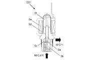
続いて、ブレーキECU6は、入力弁531への入力電力を徐々に減少させていく(S303)。入力弁531は、概念的に説明すると、例えば図4に示すように、配管を塞ぐ弁部材5aと、弁部材5aをマスタシリンダ1側に向けて付勢する付勢部材5bと、を備えている。入力弁531への入力電力が増加すると付勢部材5bの付勢力はソレノイド5cにより大きくなり、入力電力が減少すると付勢部材5bの付勢力はソレノイド5cにより小さくなる。つまり、入力電力を徐々に減少させていくと、ある時点で入力弁531が上記所定差圧に負けて開状態となる。入力弁531が開状態となると、ブレーキ液が高圧のマスタシリンダ1側からホイルシリンダ541〜544側に流れる。これにより、マスタ圧が減少し、サーボ圧によりマスタピストン14、15が前進する。第一マスタピストン14の前進に伴い第二反力室1Cの体積が減少し、第二反力室1Cのブレーキ液がストロークシミュレータ21に流れ、補助ピストン212が押し込まれて反力圧室214の圧力が上昇する。
Subsequently, the
ブレーキECU6は、入力電力を漸減させるとともに、圧力センサ73が測定する圧力が予め設定された閾値(所定圧)以上になったか否かを判定する(S304)。圧力センサ73の圧力値が閾値以上となった場合(S304:Yes)、ブレーキECU6は、入力弁531が開弁したと判定し、圧力値が閾値以上となった際の入力弁531への入力電力を検出して記憶する(S305)。これにより、所定差圧に対する入力弁531の開弁電流、最小開弁電圧、又は最小開弁電力が取得できる。さらに、本実施形態では、ブレーキECU6は、入力弁531が開弁したと判定した際、入力弁531を閉弁するように入力電力を制御する(S306)。すなわち、ブレーキECU6は、開弁検出後、入力電力を入力弁531が閉弁する値まで上昇させる。これにより、入力弁531の開弁によるマスタシリンダ1からホイルシリンダ側へのブレーキ液流出が抑制され、ストロークシミュレータ211の補助ピストン212のストローク量の増加が抑制される。マスタシリンダ1のブレーキ液が流出するとマスタピストン14、15が前進し、第一マスタシリンダ14の前進に伴い第二反力室1Cの容積が減少し、補助ピストン212が前進する。
The
このように、ブレーキECU6は、一定電圧下において、入力弁531への電流値を漸減させて、第一差圧P1に対する入力弁531の第一開弁電流(「第一開弁電力」に相当する)I1を取得する。また、上記同様の制御により、第一差圧P1と異なる第二差圧P2(ここではP1<P2)に対する入力弁531の第二開弁電流(「第二開弁電力」に相当する)I2を取得することができる。第一開弁電流I1と第二開弁電流I2に基づき、入力弁531の作動特性(IP特性)が算出できる。
Thus, the
なお、本明細書において、「入力電力の制御」は、入力電力の電流制御及び電圧制御のいずれも含む概念である。また、「入力電力の検出」は、入力電流の検出及び入力電圧の検出を含む概念である。また、ステップ304において、圧力センサ73の圧力値の変化が所定幅以上となったか否かを検出するように設定しても良い。つまり、入力弁531開弁を検出するための閾値は、第二反力室1Cの圧力の変化量(幅)としても良い。
In the present specification, “control of input power” is a concept including both current control and voltage control of input power. The “input power detection” is a concept including input current detection and input voltage detection. Further, in step 304, it may be set to detect whether or not the change in the pressure value of the
1つの入力弁531に対する開弁電流の取得は上記のように実行でき、本実施形態では、各ホイルシリンダ541〜544に対応する入力弁531の作動特性を連続的に設定する制御を実行する。ここで、マスタピストン14、15をその初期位置側に戻すことなく複数の入力弁531の開弁電流を連続して取得する処理を「開弁電流連続取得処理(「開弁電力連続取得処理」に相当する)」とも称する。また、以下、説明において、車輪5FRのホイルシリンダ541に対応する入力弁531aとし、車輪5FLのホイルシリンダ542に対応する入力弁531bとし、車輪5RRのホイルシリンダ543に対応する入力弁531cとし、車輪5RLのホイルシリンダ544に対応する入力弁531dとする。
Acquisition of the valve opening current for one
本実施形態の作動特性設定制御では、図5に示すように、まず、マスタシリンダ1側とホイルシリンダ541〜544側との間に第一差圧P1を発生させて入力弁531dの第一開弁電流Id1を取得する。第一開弁電流Id1の取得に関して、ブレーキECU6は、入力弁531dの入力電力(制御電流)を、漸減させていき、入力弁531dが開弁したと判定した後に、入力弁531dが閉弁する電流値まで一気に上昇させる。
In the operation characteristic setting control of the present embodiment, as shown in FIG. 5, first, a first differential pressure P1 is generated between the master cylinder 1 side and the
第一開弁電流Id1取得後、入力弁531dは閉弁され、ブレーキ液の流れが止まるとともにマスタシリンダ1側とホイルシリンダ541〜544側との間の差圧の変動は最小限で抑えられる。これにより、補助ピストン212の前進(ストローク量増加)も抑制される。また、入力弁531dが閉弁されるため、スタシリンダ1側とホイルシリンダ541〜544側との間の差圧が短時間で安定し、素早く次の開弁電流取得制御に移ることができる。ホイルシリンダ544の圧力は、入力弁531dの開弁により上昇し、入力弁531dの閉弁により一定に維持される。補助ピストン212のストローク量は、入力弁531dの開弁時に増加し、入力弁531dの閉弁により増加が停止する。
After obtaining the first valve opening current Id1, the
続いて、ブレーキECU6は、第一差圧P1を維持して入力弁531aの第一開弁電流Ia1を取得する。第一開弁電流Ia1の取得に関して、ブレーキECU6は、入力弁531dを閉弁させた後に、入力弁531aの入力電力の漸減制御を開始する。そして、ブレーキECU6は、入力弁531aが開弁したと判定した後、入力弁531aの入力電力を、入力弁531aが閉弁する電流値まで一気に上昇させる。
Subsequently, the
ホイルシリンダ541の圧力は、入力弁531aの開弁により上昇し、入力弁531aの閉弁により一定に維持される。油量剛性が低いホイルシリンダ541、542のほうが、油量剛性が高いホイルシリンダ543、544よりもブレーキ液は流入しやすい。ホイルシリンダ541は、油量剛性が低いため、入力弁531aの開弁時に、入力弁531dの開弁時よりも大量のブレーキ液が流入する。これにより、補助ピストン212のストローク量は、入力弁531dの開弁時よりも大きくなる。補助ピストン212のストローク量は、入力弁531aの開弁時に増加し、入力弁531aの閉弁により増加が停止する。
The pressure in the
続いて、ブレーキECU6は、スタシリンダ1側とホイルシリンダ541〜544側との間に第二差圧P2を発生させて入力弁531cの第二開弁電流Ic2を取得する。第二開弁電流Ic2の取得に関して、ブレーキECU6は、入力弁531aを閉弁させた後に、入力弁531cの入力電力の漸減制御を開始する。そして、ブレーキECU6は、入力弁531cが開弁したと判定した後、入力弁531cの入力電力を、入力弁531cが閉弁する電流値まで一気に上昇させる。
Subsequently, the
ホイルシリンダ543の圧力は、入力弁531cの開弁により上昇し、入力弁531cの閉弁により一定に維持される。第二差圧P2は、第一差圧P1よりも大きいため、入力弁531c開弁時にホイルシリンダ543に流れるブレーキ液の量が大きくなり、ホイルシリンダ543の圧力上昇度もその分増加する。補助ピストン212のストローク量は、第二差圧P2を発生させるに伴い増加し、一定となった後、入力弁531c開弁により増加し、入力弁531c閉弁により増加が停止する。この時点で、補助ピストン212のストローク量は、上限ストローク量よりも小さい。したがって、最後の(4輪目の)入力弁531bの開弁によるストローク量の変動(圧力センサ73の圧力値の変動)は検出可能である。
The pressure in the
続いて、ブレーキECU6は、第二差圧P2を維持して入力弁531bの第二開弁電流Ib2を取得する。第二開弁電流Ib2の取得に関して、ブレーキECU6は、入力弁531cを閉弁させた後に、入力弁531bの入力電力の漸減制御を開始する。そして、ブレーキECU6は、入力弁531bが開弁したと判定した後、入力弁531bの入力電力を、入力弁531bが閉弁する電流値まで一気に上昇させる。ただし、最後の入力弁531bに対しては、開弁後の閉弁制御を省略しても良い。
Subsequently, the
ホイルシリンダ542の圧力は、入力弁531bの開弁により上昇し、入力弁531bの閉弁により一定に維持される。第二差圧P2は、第一差圧P1よりも大きいため、入力弁531b開弁時にホイルシリンダ542に流れるブレーキ液の量が大きくなり、ホイルシリンダ542の圧力上昇度もその分増加する。また、ホイルシリンダ542は、油量剛性が低いため、油量剛性が高いホイルシリンダ543、544よりも大量のブレーキ液が流入する。補助ピストン212のストローク量は、入力弁531b開弁により増加し、入力弁531b閉弁により増加が停止する。本実施形態では、補助ピストン212は、入力弁531b開弁中にストローク量が上限ストローク量に達し、入力弁531b閉弁前に停止している。
The pressure in the
上記制御により、1回の開弁電流連続取得処理ですべての入力弁531a〜531dに対して、第一開弁電流I1又は第二開弁電流I2を取得することができる。入力弁531a〜531d開弁判定後に入力弁531a〜531dを閉弁することにより、短時間で次の入力弁531a〜531dの開弁電流連続取得処理に移ることができる上、ホイルシリンダ541〜544側へのブレーキ液の流出を抑制して補助ピストン212のストローク量の増加を抑制することができる。
With the above control, the first valve opening current I1 or the second valve opening current I2 can be acquired for all the
また、上記のように、1回の開弁電流連続取得処理で、第一開弁電流I1と第二開弁電流I2とを混ぜて取得することで、1回の開弁電流連続取得処理ですべて第二開弁電流I2を取得する場合よりも補助ピストン212の合計ストローク量を低減させ、最後の入力弁531の開弁電流取得前に補助ピストン212のストローク量が上限ストローク量に達することを抑制することができる。また、最後の入力弁531の開弁電流取得制御対象を、入力弁531a〜531dのうち油量剛性が低い入力弁531b又は531aとすることで、最後の入力弁531の開弁電流取得前に補助ピストン212のストローク量が上限ストローク量に達することを抑制することができる。また、最後の入力弁531の最小電流取得制御対象を、第二差圧P2に対する第二開弁電流I2とすることで、最後の入力弁531の開弁電流取得前に補助ピストン212のストローク量が上限ストローク量に達することを抑制することができる。これらにより、1回の開弁電流連続取得処理ですべての入力弁531a〜531dに対して第一開弁電流I1又は第二開弁電流I2を取得することができ、本実施形態の場合合計2回の開弁電流連続取得処理ですべての入力弁531a〜531dの作動特性を設定することができる。つまり、最小の開弁電流連続取得処理回数ですべての入力弁531a〜531dの作動特性が設定され、作動特性設定時間が短縮される。
In addition, as described above, by acquiring and mixing the first valve opening current I1 and the second valve opening current I2 in a single valve opening current continuous acquisition process, in one valve opening current continuous acquisition process The total stroke amount of the
1回目の取得制御が終わると(入力弁531b閉弁後)、ブレーキECU6は、サーボ圧を制御してマスタ圧を低下させ、マスタピストン14、15を初期位置に戻して2回目の開弁電流連続取得処理を開始する。第一マスタピストン14が初期位置に戻ることで、補助ピストン212も初期位置に戻る。すなわち、補助ピストン212のストローク量はほぼ0となる。ブレーキECU6は、すべての入力弁531a〜531dを開弁させた後、マスタ圧を上昇させつつ、すべての入力弁531a〜531dを閉弁させる。
When the first acquisition control is finished (after the
ブレーキECU6は、スタシリンダ1側とホイルシリンダ541〜544側との間に第一差圧P1を発生させ、入力弁531cの第一開弁電流Ic1を取得する。第一最小電流Ic1を取得する際、ブレーキECU6は、1回目の取得制御時に取得した入力弁531cの第二開弁電流Ic2の値に基づいて、入力電力を所定値まで一気に減少させる。入力弁531cの第二開弁電流Ic2が分かれば、入力弁531cの作動特性が所定のばらつき範囲内である程度予想でき、第一開弁電流Ic1となる電流値の範囲を推定することができる。
The
ブレーキECU6は、実験又はシミュレーション等により求められた、一方の開弁電流に対応する他方の開弁電流のばらつき範囲を記憶している。したがって、ブレーキECU6は、一方の開弁電流の値に応じて、記憶された他方の開弁電流のばらつき範囲の最大電流値よりも少し大きい電流値(所定値)まで、入力電力を単位時間当たりの変化量を大きくして素早く減少させることができる。所定値までの入力電力の減少速度は、漸減制御時の減少速度よりも速くなっている。
The
このように、ブレーキECU6は、入力弁531cの入力電力を第二開弁電流Ic2に応じた所定値まで一気に減少させた後、入力電力を徐々に減少させる漸減制御を開始する。ブレーキECU6は、入力弁531cが開弁したと判定した後、入力弁531cを閉弁すべく一気に入力電力を上昇させ、入力弁531cを閉弁させる。上記のように、ブレーキECU6が漸減制御前に入力電力を所定値まで大きな変化量で減少させるため、開弁電流の取得までの時間を短くできる上、漸減制御における変化速度は変えていないため、開弁検出精度は維持される。
As described above, the
2回目の開弁電流連続取得処理では、すべての入力弁531a〜531dに対し、上記のように、一方の開弁電流に応じて決定される所定値まで入力電力を一気に減少させ、その後漸減制御を開始する。その他の制御については、1回目の取得制御と同様であるため、以下、簡単に説明する。ブレーキECU6は、入力弁531cの第一開弁電流Ic1を取得後、第一差圧P1を維持して入力弁531bの第一開弁電流Ib1を取得する。続いて、ブレーキECU6は、第一開弁電流Ib1を取得後、スタシリンダ1側とホイルシリンダ541〜544側との間に第二差圧P2を発生させ、入力弁531dの第二開弁電流Id2を取得する。続いて、ブレーキECU6は、第二開弁電流Id2を取得後、入力弁531aの第二開弁電流Ia2を取得する。
In the second valve opening current continuous acquisition process, as described above, the input power is reduced to a predetermined value determined according to one of the valve opening currents for all the
以上、本実施形態の場合、2回の開弁電流連続取得処理により、ブレーキECU6は、すべての入力弁531a〜531dに対して第一開弁電流I1及び第二開弁電流I2を取得でき、両開弁電流I1、I2に基づいて各入力弁531a〜531dの作動特性を設定することができる。
As described above, in the case of the present embodiment, the
また、本実施形態では、入力弁531a〜531dを閉弁させる前にある程度マスタ圧を上昇させている。ストロークシミュレータ21は、所定圧力以上となると、単位ストローク量あたりの圧力変化量が大きくなる特性を有している。本実施形態では、この特性を利用して、より精度良く入力弁531開弁時の入力電流を取得することができる。具体的に、入力弁531開弁時の第一マスタピストン14の前進に伴うピストン212の変位が少量の時点でも、圧力センサ73が示す圧力は大きく変化(上昇)する。このため、ブレーキECU6は、第一マスタピストン14の前進、すなわち入力弁531の開弁時期を感度良く検出することができる。なお、図5では、入力弁531a〜531dを閉弁させる前のマスタ圧上昇に伴う、ホイルシリンダ541〜544の圧力上昇及び補助ピストン212のストローク量増加は省略している。
In the present embodiment, the master pressure is increased to some extent before the
ここで、第一実施形態の上記作動特性設定制御の流れについて簡単に説明する。図6に示すように、ブレーキECU6は、まず、第一開弁電流Id1を取得し(S601)、それに伴い入力弁531dを閉弁させる(S602)。続いて、ブレーキECU6は、第一開弁電流Ia1を取得し(S603)、それに伴い入力弁531aを閉弁させる(S604)。続いて、ブレーキECU6は、第二開弁電流Ic2を取得し(S605)、それに伴い入力弁53cを閉弁させる(S606)。続いて、ブレーキECU6は、第二開弁電流Ib2を取得し(S607)、それに伴い入力弁531bを閉弁させる(S608)。これにより、1回目の開弁電流連続取得処理が完了する。
Here, the flow of the operation characteristic setting control of the first embodiment will be briefly described. As shown in FIG. 6, the
続いて、図7に示すように、ブレーキECU6は、マスタピストン14、15を初期位置に移動させ(S609)、マスタ圧を上昇させるとともにすべての入力弁531a〜531dを閉弁させる。そして、ブレーキECU6は、入力弁531bの入力電力を所定値まで減少させ(S610)、その後漸減制御により第一開弁電流Ib1を取得して(S611)、入力弁531bを閉弁させる(S612)。続いて同様に、ブレーキECU6は、入力弁531cの入力電力を所定値まで減少させ(S613)、その後漸減制御により第一開弁電流Ic1を取得して(S614)、入力弁531cを閉弁させる(S615)。続いて同様に、ブレーキECU6は、入力弁531dの入力電力を所定値まで減少させ(S616)、その後漸減制御により第二開弁電流Id2を取得して(S617)、入力弁531dを閉弁させる(S618)。
Subsequently, as shown in FIG. 7, the
最後に、ブレーキECU6は、入力弁531aの入力電力を所定値まで減少させ(S619)、その後漸減制御により第二開弁電流Ia2を取得する(S620)。これにより、ブレーキECU6は、第一開弁電流Ia1、Ib1、Ic1、Id1及び第二開弁電流Ia2、Ib2、Ic2、Id2を取得する。ブレーキECU6は、ステップS601〜S620において、開弁電力取得手段として機能する。そして、ブレーキECU6は、取得した開弁電流に基づいて各入力弁531a〜531dの作動特性を設定する(S621)。ブレーキECU6は、ステップS621において、作動特性設定手段として機能する。また、ブレーキECU6は、マスタシリンダ1側とホイルシリンダ541〜544側との間に第一差圧P1を発生させる際、マスタシリンダ1側とホイルシリンダ541〜544側との間に第一差圧P1が発生するように減圧弁41及び増圧弁42を制御してサーボ圧を制御し、マスタシリンダ1側とホイルシリンダ541〜544側との間に第二差圧P2を発生させる際、マスタシリンダ1側とホイルシリンダ541〜544側との間に第二差圧P2が発生するように減圧弁41及び増圧弁42を制御してサーボ圧を制御する差圧発生手段として機能する。換言すると、ブレーキECU6は、機能的に、開弁電力取得手段61と、作動特性取得手段62と、差圧発生手段63と、を有している。
Finally, the
なお、開弁電流の取得順序は、上記に限られない。ただし、上記実施形態のように、すべてのホイルシリンダ541〜544のうち油量剛性が低いホイルシリンダ541、542に設けられた入力弁531a、531bの第二開弁電流Ia2、Ib2を最後に取得することが好ましい。また、上記実施形態のように、1回の開弁電流連続取得処理において、第一開弁電流と第二開弁電流とを混ぜて、特に均等に(4輪の場合2つずつ)混ぜて取得することが好ましい。このとき、ブレーキECU6は、一方の開弁電流(同じ差圧に対する開弁電流)を連続して取得することが好ましい。また、作動特性設定対象は、ABS53の入力弁531に限られず、マスタシリンダ1とホイルシリンダ541〜544の間に設けられ、マスタシリンダ1とホイルシリンダ541〜544の間のブレーキ液の流れを制御する電磁弁であれば良い。
The order of obtaining the valve opening current is not limited to the above. However, as in the above embodiment, the second valve opening currents Ia2 and Ib2 of the
<第二実施形態>
第二実施形態の車両用制動装置は、構成上では、図8に示すように、入力弁531の上流側(マスタシリンダ1と入力弁531の間)に圧力センサ76を有する点で第一実施形態と異なっている。具体的に、第二実施形態では、圧力センサ76が、配管51、52に対して設けられている。
<Second embodiment>
As shown in FIG. 8, the vehicular braking apparatus according to the second embodiment is the first embodiment in that a
第二実施形態のブレーキECU6は、第一実施形態同様、入力弁531が閉弁するように入力電力を変化させた後に、当該入力電力を時間経過に伴って入力弁531の開弁側に変化させつつ(漸減制御しつつ)、入力弁531が開弁したときの入力電力である開弁電力を取得する。ここで、第一実施形態では圧力センサ73の圧力値に基づいて入力弁531の開弁判定を行うが、第二実施形態では、圧力センサ76の圧力値に基づいて入力弁531の開弁判定を行う。したがって、補助ピストン212のストローク量が上限ストローク量に達した後でも、マスタピストン14、15のストローク量が上限ストローク量に達しない限り、開弁電流を取得することができる。
As in the first embodiment, the
また、第二実施形態では、ブレーキECU6は、入力弁531が開弁したと判定した後に、入力弁531の入力電力を漸減制御時より大きい単位時間当たりの変化量で開弁側に変化させる。つまり、ブレーキECU6は、開弁検出後、漸減制御時より高速に入力電力を減少させる。第二実施形態の作動特性設定制御は、上記以外は第一実施形態と同様であるため、以下簡単に説明する。
In the second embodiment, after determining that the
図9〜図11に示すように、ブレーキECU6は、第一開弁電流Id1を取得し(S901)、それに伴い入力弁531dへの入力電力を一気に減少させ入力弁531dを完全に開弁させる(S902)。続いて、ブレーキECU6は、第一開弁電流Ia1を取得し(S903)、入力弁531aの入力電力を一気に減少させ入力弁531aを完全に開弁させる(S904)。続いて、ブレーキECU6は、第二開弁電流Ic2を取得し(S905)、入力弁531cの入力電力を一気に減少させ入力弁531cを完全に開弁させる(S906)。続いて、ブレーキECU6は、第二開弁電流Ib2を取得し(S907)、入力弁531bの入力電力を一気に減少させ入力弁531bを完全に開弁させる(S908)。
As shown in FIGS. 9 to 11, the
続いて、ブレーキECU6は、マスタピストン14、15を初期位置に移動させ(S909)、マスタ圧を上昇させるとともにすべての入力弁531a〜531dを閉弁させる。そして、ブレーキECU6は、第二開弁電流Ic2に応じた所定値まで入力弁531cの入力電力を一気に減少させ(S910)、その後漸減制御により第一開弁電流Ic1を取得して(S911)、入力弁531cを完全に開弁させる(S912)。同様に、ブレーキECU6は、第二開弁電流Ib2に応じた所定値まで入力弁531bの入力電力を一気に減少させ(S913)、その後漸減制御により第一開弁電流Ib1を取得して(S914)、入力弁531bを完全に開弁させる(S915)。同様に、ブレーキECU6は、第一開弁電流Id1に応じた所定値まで入力弁531dの入力電力を一気に減少させ(S916)、その後漸減制御により第二開弁電流Id2を取得して(S917)、入力弁531dを完全に開弁させる(S918)。同様に、ブレーキECU6は、第一開弁電流Ia1に応じた所定値まで入力弁531aの入力電力を一気に減少させ(S919)、その後漸減制御により第二開弁電流Ia2を取得する(S920)。そして、ブレーキECU6は、取得した開弁電流に基づいて各入力弁531a〜531dの作動特性を設定する(S921)。なお、図9では、図5と同様に、入力弁531a〜531dを開弁させる前のマスタ圧上昇に伴う、ホイルシリンダ541〜544の圧力上昇及び補助ピストン212のストローク量増加を省略している。
Subsequently, the
第二実施形態によれば、入力弁531の開弁が検出された後に、入力弁531の入力電力を一気に減少させ入力弁531を完全に開弁させるため、短時間でマスタシリンダ1とホイルシリンダ(541〜544のうちの1つ)との差圧が無くなり、素早く次の入力弁531の開弁電流取得制御を開始できる。これにより、作動特性設定時間の短縮が可能となる。
According to the second embodiment, after the opening of the
また、第一実施形態同様、1回の取得制御で第一開弁電流I1と第二開弁電流I2とを混ぜて取得すること、油量剛性の低いホイルシリンダ541、542に設けられた入力弁531a、531bの開弁電流を最後に取得すること、及び第二開弁電流を最後に取得することにより、最後の入力弁531の開弁電流取得前にマスタピストン14、15のストローク量が上限ストローク量に達することを抑制することができる。
Further, as in the first embodiment, the first valve opening current I1 and the second valve opening current I2 are mixed and acquired by one acquisition control, and the input provided in the
ただし、製造コスト及び作動特性の設定精度の面では、第一実施形態が第二実施形態よりも有利である。第一実施形態では、新たに圧力センサを設ける必要がなく、部品点数及び製造コストの増加を抑制することができる。 However, the first embodiment is more advantageous than the second embodiment in terms of manufacturing cost and setting accuracy of operating characteristics. In the first embodiment, it is not necessary to newly provide a pressure sensor, and an increase in the number of parts and manufacturing cost can be suppressed.
また、第一実施形態では、マスタピストン1のストローク位置に応じた第二反力室1Cの液圧に基づいて作動特性を取得する。ここで、第二反力室1Cは、マスタシリンダ1やホイルシリンダ541〜544よりも簡素な構成で実現可能である。そのため、マスタピストン1のストローク位置に応じた液圧が発生する第二反力室1C内の液圧は、入力弁531が設けられた管路内の液圧に比して、個体間のばらつきが小さい。そのため、第一実施形態によれば、入力弁531の開弁に伴う圧力変化に基づいて入力弁531の作動特性を設定するに際し、個体間のばらつきの影響を低減して、作動特性を精度良く設定することができる。なお、図では、入力弁531a〜531dを閉弁させる前のマスタ圧上昇に伴うホイルシリンダ541〜544の圧力上昇は省略して表す。また、入力弁531のホイルシリンダ541〜544側に圧力計を設けても良い。
In the first embodiment, the operation characteristic is acquired based on the hydraulic pressure in the second reaction force chamber 1 </ b> C corresponding to the stroke position of the master piston 1. Here, the second reaction force chamber 1 </ b> C can be realized with a simpler configuration than the master cylinder 1 and the
1:マスタシリンダ、
11:メインシリンダ、12:カバーシリンダ、
13:入力ピストン、
14:第一マスタピストン、15:第二マスタピストン、
1A:サーボ室、
1B:第一反力室、1C:第二反力室(補助室)、
1D:第一マスタ室、1E:第二マスタ室、
2:反力発生装置、22:離間ロック弁、3:反力弁、
4:サーボ圧発生装置、
41:減圧弁、42:増圧弁、431:アキュムレータ、
5:ブレーキ、51a、52a:切替弁、
531、531a、531b、531c、531d:入力弁(電磁弁)、
541、542、543、544:ホイルシリンダ、
5FR、5FL、5RR、5RL:車輪、
6:ブレーキECU(開弁電力取得手段、作動特性設定手段、差圧発生手段)、
61:開弁電力取得手段、62:作動特性設定手段、
63:第一差圧発生手段、
73、74、75、76:圧力センサ
1: Master cylinder,
11: Main cylinder, 12: Cover cylinder,
13: Input piston,
14: first master piston, 15: second master piston,
1A: servo room
1B: first reaction force chamber, 1C: second reaction force chamber (auxiliary chamber),
1D: first master room, 1E: second master room,
2: reaction force generator, 22: separation lock valve, 3: reaction force valve,
4: Servo pressure generator,
41: Pressure reducing valve, 42: Pressure increasing valve, 431: Accumulator,
5: Brake, 51a, 52a: Switching valve,
531, 531a, 531b, 531c, 531d: input valve (solenoid valve),
541, 542, 543, 544: wheel cylinders,
5FR, 5FL, 5RR, 5RL: wheels,
6: Brake ECU (valve opening power acquisition means, operation characteristic setting means, differential pressure generation means),
61: valve opening power acquisition means, 62: operating characteristic setting means,
63: first differential pressure generating means,
73, 74, 75, 76: Pressure sensor
Claims (5)
前記電磁弁の前記マスタシリンダ側と前記ホイルシリンダ側とに所定の差圧を発生させる差圧制御手段(6(63))と、
前記電磁弁が閉弁するように前記入力電力を変化させた後に、前記差圧制御手段により前記所定の差圧を発生させている状態で、当該入力電力を時間経過に伴って前記電磁弁の開弁側に変化させつつ、前記電磁弁が開弁したときの前記入力電力を開弁電力として取得する開弁電力取得手段(6(61))と、
前記開弁電力取得手段により前記所定の差圧に対して取得された前記開弁電力に基づいて、前記電磁弁における当該電磁弁の入力電力と当該電磁弁の前記マスタシリンダ側及び前記ホイルシリンダ側の差圧との関係である作動特性を設定する作動特性設定手段(6(62))と、
を備える車両用制動制御装置において、
前記開弁電力取得手段(6(61))は、前記開弁電力の取得に伴って、前記電磁弁の開弁前よりも大きい単位時間当たりの変化量で前記電磁弁の閉弁側又は開弁側に前記入力電力を変化させ、
前記作動特性設定手段(6(62))は、前記差圧制御手段が発生させた所定の第一差圧に対して前記開弁電力取得手段により取得された前記開弁電力である第一開弁電力と、前記差圧制御手段が発生させた前記第一差圧とは異なる所定の第二差圧に対して前記開弁電力取得手段により取得された前記開弁電力である第二開弁電力とに基づいて、前記電磁弁の作動特性を設定し、
前記開弁電力取得手段(6(61))は、前記電磁弁の前記第一開弁電力を取得した後に同一の前記電磁弁の前記第二開弁電力を取得するに際し、前記第一開弁電力に応じた前記電磁弁が開弁しない所定値まで比較的大きな単位時間当たりの変化量で前記入力電力を前記電磁弁の開弁側に変化させた上で、当該入力電力を、比較的小さな単位時間当たりの変化量で前記電磁弁の開弁側に変化させつつ、前記電磁弁が開弁したときの前記入力電力を前記第二開弁電力として取得する車両用制動制御装置。 A solenoid valve (between the master cylinder (1) and the wheel cylinders (541, 542, 543, 544) for controlling the flow of brake fluid between the master cylinder and the wheel cylinder according to input power ( 531), and is applied to a vehicle braking device.
Differential pressure control means (6 (63)) for generating a predetermined differential pressure between the master cylinder side and the wheel cylinder side of the solenoid valve;
After changing the input power so that the solenoid valve is closed, the input power is changed over time with the differential pressure control means generating the predetermined differential pressure. Valve opening power acquisition means (6 (61)) for acquiring the input power as the valve opening power when the solenoid valve is opened while changing to the valve opening side;
Based on the valve opening power acquired with respect to the predetermined differential pressure by the valve opening power acquisition means, the input power of the solenoid valve in the solenoid valve and the master cylinder side and the wheel cylinder side of the solenoid valve An operating characteristic setting means (6 (62)) for setting an operating characteristic which is a relationship with the differential pressure of
In a vehicle brake control device comprising:
The valve opening power acquisition means (6 (61)) is adapted to acquire the valve opening power with a larger amount of change per unit time than before opening of the solenoid valve. Change the input power to the valve side,
The operating characteristic setting means (6 (62)) is a first opening that is the valve opening power acquired by the valve opening power acquisition means with respect to a predetermined first differential pressure generated by the differential pressure control means. Second valve opening that is the valve opening power acquired by the valve opening power acquisition means for a predetermined second differential pressure different from the valve power and the first differential pressure generated by the differential pressure control means Based on the power and set the operating characteristics of the solenoid valve,
The valve opening power acquisition means (6 (61)) obtains the second valve opening power of the same solenoid valve after acquiring the first valve opening power of the solenoid valve. After changing the input power to the valve opening side of the solenoid valve by a relatively large amount of change per unit time up to a predetermined value that does not open the solenoid valve according to the power, the input power is relatively small A vehicular braking control device that acquires the input power when the solenoid valve is opened as the second valve opening power while changing the solenoid valve to the valve opening side with a change amount per unit time .
前記電磁弁の前記マスタシリンダ側と前記ホイルシリンダ側とに所定の差圧を発生させる差圧制御手段(6(63))と、
前記電磁弁が閉弁するように前記入力電力を変化させた後に、前記差圧制御手段により前記所定の差圧を発生させている状態で、当該入力電力を時間経過に伴って前記電磁弁の開弁側に変化させつつ、前記電磁弁が開弁したときの前記入力電力を開弁電力として取得する開弁電力取得手段(6(61))と、
前記開弁電力取得手段により前記所定の差圧に対して取得された前記開弁電力に基づいて、前記電磁弁における当該電磁弁の入力電力と当該電磁弁の前記マスタシリンダ側及び前記ホイルシリンダ側の差圧との関係である作動特性を設定する作動特性設定手段(6(62))と、
を備える車両用制動制御装置において、
前記マスタシリンダのマスタピストン(14)の変位に応じて容積が変化する補助室(1C)に接続されている補助シリンダ(211)、及び前記補助室の容積変化に応じて前記補助シリンダ内を摺動する補助ピストン(212)を有するとともに、前記マスタピストンのストローク位置に応じた補助液圧を前記補助室に発生させる補助液圧発生部(21)を備え、
前記開弁電力取得手段(6(61))は、前記開弁電力の取得に伴って、前記電磁弁の開弁前よりも大きい単位時間当たりの変化量で前記電磁弁の閉弁側又は開弁側に前記入力電力を変化させ、
前記開弁電力取得手段(6(61))は、前記補助液圧に基づいて前記電磁弁が開弁したことを判定し、前記マスタピストンをその初期位置側に戻すことなく前記複数の電磁弁の前記開弁電力を連続して取得するに際し、前記開弁電力の取得に伴って前記電磁弁の閉弁側に前記入力電力を変化させ、
前記作動特性設定手段は、前記開弁電力取得手段により取得された複数の前記開弁電力に基づいて前記作動特性を設定する車両用制動制御装置。 A solenoid valve (between the master cylinder (1) and the wheel cylinders (541, 542, 543, 544) for controlling the flow of brake fluid between the master cylinder and the wheel cylinder according to input power ( 531), and is applied to a vehicle braking device.
Differential pressure control means (6 (63)) for generating a predetermined differential pressure between the master cylinder side and the wheel cylinder side of the solenoid valve;
After changing the input power so that the solenoid valve is closed, the input power is changed over time with the differential pressure control means generating the predetermined differential pressure. Valve opening power acquisition means (6 (61)) for acquiring the input power as the valve opening power when the solenoid valve is opened while changing to the valve opening side;
Based on the valve opening power acquired with respect to the predetermined differential pressure by the valve opening power acquisition means, the input power of the solenoid valve in the solenoid valve and the master cylinder side and the wheel cylinder side of the solenoid valve An operating characteristic setting means (6 (62)) for setting an operating characteristic which is a relationship with the differential pressure of
In a vehicle brake control device comprising:
The auxiliary cylinder (211) connected to the auxiliary chamber (1C) whose volume changes according to the displacement of the master piston (14) of the master cylinder, and the inside of the auxiliary cylinder slides according to the volume change of the auxiliary chamber. An auxiliary hydraulic pressure generating section (21) that has an auxiliary piston (212) that moves, and generates an auxiliary hydraulic pressure in the auxiliary chamber according to a stroke position of the master piston;
The valve opening power acquisition means (6 (61)) is adapted to acquire the valve opening power with a larger amount of change per unit time than before opening of the solenoid valve. Change the input power to the valve side,
The valve opening power acquisition means (6 (61)) determines that the solenoid valve is opened based on the auxiliary hydraulic pressure, and the plurality of solenoid valves without returning the master piston to the initial position side. When continuously acquiring the valve opening power, the input power is changed to the valve closing side of the electromagnetic valve with the acquisition of the valve opening power,
The operating characteristic setting unit is a vehicle braking control device that sets the operating characteristic based on a plurality of the valve opening powers acquired by the valve opening power acquisition unit .
前記マスタシリンダのマスタピストン(14)の変位に応じて容積が変化する補助室(1C)に接続されている補助シリンダ(211)、及び前記補助室の容積変化に応じて前記補助シリンダ内を摺動する補助ピストン(212)を有するとともに、前記マスタピストンのストローク位置に応じた補助液圧を前記補助室に発生させる補助液圧発生部(21)と、
を備え、
前記開弁電力取得手段(6(61))は、前記補助液圧に基づいて前記電磁弁が開弁したことを判定し、前記マスタピストンをその初期位置側に戻すことなく前記複数の電磁弁の前記開弁電力を連続して取得するに際し、前記複数のホイルシリンダのうち前記ホイルシリンダに付与される液圧に対する同ホイルシリンダに流れ込むブレーキ液の液量が比較的大きいホイルシリンダに対して設けられた電磁弁の前記開弁電力を最後に取得する請求項1又は2に記載の車両用制動制御装置。 Applied to a vehicle braking device in which the electromagnetic valve is provided for each of the plurality of wheel cylinders;
The auxiliary cylinder (211) connected to the auxiliary chamber (1C) whose volume changes according to the displacement of the master piston (14) of the master cylinder, and the inside of the auxiliary cylinder slides according to the volume change of the auxiliary chamber. An auxiliary hydraulic pressure generating section (21) that has an auxiliary piston (212) that moves, and generates an auxiliary hydraulic pressure in the auxiliary chamber according to a stroke position of the master piston;
With
The valve opening power acquisition means (6 (61)) determines that the solenoid valve is opened based on the auxiliary hydraulic pressure, and the plurality of solenoid valves without returning the master piston to the initial position side. When continuously obtaining the valve opening power of the plurality of wheel cylinders, it is provided for a wheel cylinder in which the amount of brake fluid flowing into the wheel cylinder with respect to the hydraulic pressure applied to the wheel cylinder is relatively large. The vehicular braking control device according to claim 1 or 2 , wherein the valve opening power of the obtained electromagnetic valve is acquired last.
前記作動特性設定手段(6(62))は、前記差圧制御手段が発生させた所定の第一差圧に対して前記開弁電力取得手段により取得された前記開弁電力である第一開弁電力と、前記差圧制御手段が発生させた前記第一差圧よりも大きい第二差圧に対して前記開弁電力取得手段により取得された前記開弁電力である第二開弁電力とに基づいて、前記電磁弁の作動特性を設定し、
前記開弁電力取得手段(6(61))は、前記補助液圧に基づいて前記電磁弁が開弁したことを判定し、前記マスタピストンをその初期位置側に戻すことなく複数の前記開弁電力を連続して取得するに際し、前記第二開弁電力を最後に取得する請求項3に記載の車両用制動制御装置。 The auxiliary cylinder (211) connected to the auxiliary chamber (1C) whose volume changes according to the displacement of the master piston (14) of the master cylinder, and the inside of the auxiliary cylinder slides according to the volume change of the auxiliary chamber. An auxiliary hydraulic pressure generating section (21) that has an auxiliary piston (212) that moves, and generates an auxiliary hydraulic pressure in the auxiliary chamber according to a stroke position of the master piston;
The operating characteristic setting means (6 (62)) is a first opening that is the valve opening power acquired by the valve opening power acquisition means with respect to a predetermined first differential pressure generated by the differential pressure control means. A valve power and a second valve opening power that is the valve opening power acquired by the valve opening power acquisition means for a second differential pressure greater than the first differential pressure generated by the differential pressure control means; On the basis of the operating characteristics of the solenoid valve,
The valve opening power acquisition means (6 (61)) determines that the electromagnetic valve has opened based on the auxiliary hydraulic pressure, and the plurality of valve opening without returning the master piston to its initial position side. The vehicular braking control device according to claim 3 , wherein the second valve opening power is finally acquired when the electric power is continuously acquired.
前記マスタシリンダのマスタピストン(14)の変位に応じて容積が変化する補助室(1C)に接続されている補助シリンダ(211)、及び前記補助室の容積変化に応じて前記補助シリンダ内を摺動する補助ピストン(212)を有するとともに、前記マスタピストンのストローク位置に応じた補助液圧を前記補助室に発生させる補助液圧発生部(21)を備え、
前記作動特性設定手段(6(62))は、前記差圧制御手段が発生させた所定の第一差圧に対して前記開弁電力取得手段により取得された前記開弁電力である第一開弁電力と、前記差圧制御手段が発生させた前記第一差圧よりも大きい第二差圧に対して前記開弁電力取得手段により取得された前記開弁電力である第二開弁電力とに基づいて、前記電磁弁の作動特性を設定し、
前記開弁電力取得手段(6(61))は、前記補助液圧に基づいて前記電磁弁が開弁したことを判定し、前記マスタピストンをその初期位置側に戻すことなく複数の前記開弁電力を連続して取得する開弁電力連続取得処理を複数回行って、前記複数の電磁弁の前記第一開弁電力及び前記第二開弁電力を取得するに際し、1回の前記開弁電力連続取得処理での取得対象のうち一部を前記第一開弁電力とし、同一の前記開弁電力連続取得処理での取得対象のうち他部を前記第二開弁電力とする請求項1〜4の何れか一項に記載の車両用制動制御装置。 Applied to a vehicle braking device in which the electromagnetic valve is provided for each of the plurality of wheel cylinders;
The auxiliary cylinder (211) connected to the auxiliary chamber (1C) whose volume changes according to the displacement of the master piston (14) of the master cylinder, and the inside of the auxiliary cylinder slides according to the volume change of the auxiliary chamber. An auxiliary hydraulic pressure generating section (21) that has an auxiliary piston (212) that moves, and generates an auxiliary hydraulic pressure in the auxiliary chamber according to a stroke position of the master piston;
The operating characteristic setting means (6 (62)) is a first opening that is the valve opening power acquired by the valve opening power acquisition means with respect to a predetermined first differential pressure generated by the differential pressure control means. A valve power and a second valve opening power that is the valve opening power acquired by the valve opening power acquisition means for a second differential pressure greater than the first differential pressure generated by the differential pressure control means; On the basis of the operating characteristics of the solenoid valve,
The valve opening power acquisition means (6 (61)) determines that the electromagnetic valve has opened based on the auxiliary hydraulic pressure, and the plurality of valve opening without returning the master piston to its initial position side. When obtaining the first valve opening power and the second valve opening power of the plurality of solenoid valves by performing the valve opening power continuous acquisition process for continuously acquiring power a plurality of times, the valve opening power is used once. A part of acquisition targets in the continuous acquisition process is the first valve opening power, and another part of the acquisition target in the same valve opening power continuous acquisition process is the second valve opening power. vehicle brake control device according to any one of the 4.
Priority Applications (4)
| Application Number | Priority Date | Filing Date | Title |
|---|---|---|---|
| JP2012141957A JP5847656B2 (en) | 2012-06-25 | 2012-06-25 | Brake control device for vehicle |
| US14/410,976 US9333960B2 (en) | 2012-06-25 | 2013-06-25 | Vehicle braking control device |
| PCT/JP2013/067339 WO2014002987A1 (en) | 2012-06-25 | 2013-06-25 | Braking control device for vehicle |
| CN201380033296.0A CN104395161B (en) | 2012-06-25 | 2013-06-25 | Vehicle brake control apparatus |
Applications Claiming Priority (1)
| Application Number | Priority Date | Filing Date | Title |
|---|---|---|---|
| JP2012141957A JP5847656B2 (en) | 2012-06-25 | 2012-06-25 | Brake control device for vehicle |
Publications (2)
| Publication Number | Publication Date |
|---|---|
| JP2014004919A JP2014004919A (en) | 2014-01-16 |
| JP5847656B2 true JP5847656B2 (en) | 2016-01-27 |
Family
ID=49783133
Family Applications (1)
| Application Number | Title | Priority Date | Filing Date |
|---|---|---|---|
| JP2012141957A Expired - Fee Related JP5847656B2 (en) | 2012-06-25 | 2012-06-25 | Brake control device for vehicle |
Country Status (4)
| Country | Link |
|---|---|
| US (1) | US9333960B2 (en) |
| JP (1) | JP5847656B2 (en) |
| CN (1) | CN104395161B (en) |
| WO (1) | WO2014002987A1 (en) |
Families Citing this family (6)
| Publication number | Priority date | Publication date | Assignee | Title |
|---|---|---|---|---|
| JP5680010B2 (en) * | 2012-03-21 | 2015-03-04 | 株式会社アドヴィックス | Braking device for vehicle |
| JP5892980B2 (en) * | 2013-06-25 | 2016-03-23 | 株式会社アドヴィックス | Braking device for vehicle |
| JP5869527B2 (en) * | 2013-07-10 | 2016-02-24 | トヨタ自動車株式会社 | Hydraulic brake system and hydraulic control device |
| JP6124834B2 (en) * | 2014-04-09 | 2017-05-10 | 株式会社アドヴィックス | Vehicle control device |
| JP7021592B2 (en) * | 2018-03-30 | 2022-02-17 | 株式会社アドヴィックス | Braking control device |
| CN112455408B (en) * | 2021-02-03 | 2021-04-16 | 天津所托瑞安汽车科技有限公司 | Control method, device, equipment and medium of brake system |
Family Cites Families (9)
| Publication number | Priority date | Publication date | Assignee | Title |
|---|---|---|---|---|
| JP4207699B2 (en) * | 2003-07-18 | 2009-01-14 | トヨタ自動車株式会社 | Fluid pressure control device and fluid pressure control method |
| JP2004237982A (en) | 2004-04-27 | 2004-08-26 | Toyota Motor Corp | Hydraulic brake device, operational characteristic acquiring device, and control valve inspecting device |
| JP4650083B2 (en) * | 2005-04-25 | 2011-03-16 | トヨタ自動車株式会社 | Hydraulic pressure control device and operating characteristic acquisition device |
| JP4395787B2 (en) * | 2006-10-05 | 2010-01-13 | トヨタ自動車株式会社 | Brake control device and brake control method |
| JP4473894B2 (en) * | 2007-07-18 | 2010-06-02 | 日信工業株式会社 | Brake hydraulic pressure control device for vehicles |
| DE102009008944B4 (en) * | 2009-02-13 | 2024-03-14 | Ipgate Ag | Brake system with simultaneous or partially simultaneous pressure build-up and pressure reduction in the wheel brakes from different wheel cylinder pressure levels and method for setting a brake pressure |
| WO2010143235A1 (en) * | 2009-06-11 | 2010-12-16 | トヨタ自動車株式会社 | Electromagnetic valve control device, and actuator |
| JP5488009B2 (en) | 2010-02-02 | 2014-05-14 | トヨタ自動車株式会社 | Brake system |
| JP2012071681A (en) * | 2010-09-28 | 2012-04-12 | Advics Co Ltd | Braking device for vehicle |
-
2012
- 2012-06-25 JP JP2012141957A patent/JP5847656B2/en not_active Expired - Fee Related
-
2013
- 2013-06-25 CN CN201380033296.0A patent/CN104395161B/en not_active Expired - Fee Related
- 2013-06-25 US US14/410,976 patent/US9333960B2/en active Active
- 2013-06-25 WO PCT/JP2013/067339 patent/WO2014002987A1/en active Application Filing
Also Published As
| Publication number | Publication date |
|---|---|
| WO2014002987A1 (en) | 2014-01-03 |
| CN104395161A (en) | 2015-03-04 |
| US20150203088A1 (en) | 2015-07-23 |
| CN104395161B (en) | 2017-03-08 |
| JP2014004919A (en) | 2014-01-16 |
| US9333960B2 (en) | 2016-05-10 |
Similar Documents
| Publication | Publication Date | Title |
|---|---|---|
| JP5847656B2 (en) | Brake control device for vehicle | |
| JP5660062B2 (en) | Braking device for vehicle | |
| JP5680010B2 (en) | Braking device for vehicle | |
| JP5989022B2 (en) | Braking device for vehicle | |
| KR101710819B1 (en) | Braking device for vehicle | |
| JP5959549B2 (en) | Braking device | |
| JP6124840B2 (en) | Braking control device | |
| JP6025762B2 (en) | Vehicle control device | |
| JP6132813B2 (en) | Braking device for vehicle | |
| CN107206988B (en) | Vehicular brake device | |
| JP2015006856A (en) | Vehicular brake apparatus | |
| JP2015143059A (en) | vehicle control device | |
| CN107848506B (en) | Vehicle brake device | |
| JP2015182640A (en) | Vehicle controlling device | |
| JP6016651B2 (en) | Braking control device | |
| JP5949093B2 (en) | Braking control device for vehicle | |
| JP5999118B2 (en) | Braking device for vehicle | |
| WO2018181218A1 (en) | Vehicle braking device | |
| JP6457179B2 (en) | Braking device |
Legal Events
| Date | Code | Title | Description |
|---|---|---|---|
| A621 | Written request for application examination |
Free format text: JAPANESE INTERMEDIATE CODE: A621 Effective date: 20140521 |
|
| A131 | Notification of reasons for refusal |
Free format text: JAPANESE INTERMEDIATE CODE: A131 Effective date: 20150526 |
|
| A521 | Request for written amendment filed |
Free format text: JAPANESE INTERMEDIATE CODE: A523 Effective date: 20150724 |
|
| TRDD | Decision of grant or rejection written | ||
| A01 | Written decision to grant a patent or to grant a registration (utility model) |
Free format text: JAPANESE INTERMEDIATE CODE: A01 Effective date: 20151104 |
|
| A61 | First payment of annual fees (during grant procedure) |
Free format text: JAPANESE INTERMEDIATE CODE: A61 Effective date: 20151125 |
|
| R150 | Certificate of patent or registration of utility model |
Ref document number: 5847656 Country of ref document: JP Free format text: JAPANESE INTERMEDIATE CODE: R150 |
|
| LAPS | Cancellation because of no payment of annual fees |