JP5846504B2 - Ceramic metal halide lamp and manufacturing method thereof - Google Patents
Ceramic metal halide lamp and manufacturing method thereof Download PDFInfo
- Publication number
- JP5846504B2 JP5846504B2 JP2013245462A JP2013245462A JP5846504B2 JP 5846504 B2 JP5846504 B2 JP 5846504B2 JP 2013245462 A JP2013245462 A JP 2013245462A JP 2013245462 A JP2013245462 A JP 2013245462A JP 5846504 B2 JP5846504 B2 JP 5846504B2
- Authority
- JP
- Japan
- Prior art keywords
- lead wire
- tube portion
- absorbing member
- gas absorbing
- metal halide
- Prior art date
- Legal status (The legal status is an assumption and is not a legal conclusion. Google has not performed a legal analysis and makes no representation as to the accuracy of the status listed.)
- Expired - Fee Related
Links
Images


Classifications
-
- H—ELECTRICITY
- H01—ELECTRIC ELEMENTS
- H01J—ELECTRIC DISCHARGE TUBES OR DISCHARGE LAMPS
- H01J61/00—Gas-discharge or vapour-discharge lamps
- H01J61/02—Details
- H01J61/36—Seals between parts of vessels; Seals for leading-in conductors; Leading-in conductors
-
- H—ELECTRICITY
- H01—ELECTRIC ELEMENTS
- H01J—ELECTRIC DISCHARGE TUBES OR DISCHARGE LAMPS
- H01J9/00—Apparatus or processes specially adapted for the manufacture, installation, removal, maintenance of electric discharge tubes, discharge lamps, or parts thereof; Recovery of material from discharge tubes or lamps
- H01J9/24—Manufacture or joining of vessels, leading-in conductors or bases
- H01J9/32—Sealing leading-in conductors
- H01J9/323—Sealing leading-in conductors into a discharge lamp or a gas-filled discharge device
Landscapes
- Engineering & Computer Science (AREA)
- Manufacturing & Machinery (AREA)
- Vessels And Coating Films For Discharge Lamps (AREA)
- Manufacture Of Electron Tubes, Discharge Lamp Vessels, Lead-In Wires, And The Like (AREA)
Description
本発明は、セラミックメタルハライドランプ及びその製造方法に関し、特に、放電容器の端部の構成に関する。 The present invention relates to a ceramic metal halide lamp and a method for manufacturing the same, and more particularly to a configuration of an end portion of a discharge vessel.
近年、セラミック製の放電容器を用いるセラミックメタルハライドランプが広く普及している。セラミックメタルハライドランプでは、放電容器が透光性アルミナ等のセラミックによって形成されているため、封入物質との反応に起因した放電容器の劣化が少なく、ランプ寿命を改善することができる。 In recent years, ceramic metal halide lamps using a ceramic discharge vessel have become widespread. In the ceramic metal halide lamp, since the discharge vessel is made of ceramic such as translucent alumina, there is little deterioration of the discharge vessel due to the reaction with the encapsulated material, and the lamp life can be improved.
セラミックメタルハライドランプの放電容器は、略回転楕円体形状の発光部とその両側の細管部(キャピラリ)からなる。細管部には電極システムがそれぞれ装着される。細管部と電極システムの間の隙間を封止材によって封止することによってシール部が形成される。シール部によって、放電容器の内部は密閉され、アルゴン等の不活性ガスと発光物質が封止される。 A discharge vessel of a ceramic metal halide lamp includes a light-emitting portion having a substantially spheroid shape and narrow tubes (capillaries) on both sides thereof. Electrode systems are respectively attached to the thin tube portions. A seal portion is formed by sealing a gap between the narrow tube portion and the electrode system with a sealant. The inside of the discharge vessel is sealed by the seal portion, and an inert gas such as argon and a luminescent material are sealed.
電極システムは、典型的には、タングステン棒によって形成された電極、導電性サーメット棒を含む電流供給導体、及び、導電性材料によって形成されたリード線を有する。電極、電流供給導体、及び、リード線は突き合わせ溶接によって接続される。 An electrode system typically has an electrode formed by a tungsten rod, a current supply conductor including a conductive cermet rod, and a lead formed by a conductive material. The electrode, current supply conductor, and lead wire are connected by butt welding.
特許文献2、3、4に開示された例では、電流供給導体が放電容器の細管部より突出しており、電流供給導体とリード線の溶接部は放電容器の細管部の外側の位置にある。このような構造では、溶接部における折れを防止するために、溶接部を補強する構造が設けられる。例えば、特許文献2には、タングステンワイヤをコイル状に捲回した補強部材の例が記載されている。 In the examples disclosed in Patent Documents 2, 3, and 4, the current supply conductor protrudes from the thin tube portion of the discharge vessel, and the weld portion between the current supply conductor and the lead wire is located outside the thin tube portion of the discharge vessel. In such a structure, a structure for reinforcing the welded portion is provided in order to prevent the welded portion from being broken. For example, Patent Document 2 describes an example of a reinforcing member obtained by winding a tungsten wire in a coil shape.
特許文献1に開示された例では、電流供給導体が放電容器の細管部の内部に収納されており、電流供給導体とリード線の溶接部は放電容器の細管部の内部にある。リード線の一部は放電容器の細管部の内部に収納され、リード線の残部は放電容器の細管部より突出している。このような構造では、溶接部に補強部材を設けない。一方、リード線は、展性及び延性に優れた金属ニオブ棒によって形成される。 In the example disclosed in Patent Document 1, the current supply conductor is housed inside the thin tube portion of the discharge vessel, and the current supply conductor and the welded portion of the lead wire are inside the thin tube portion of the discharge vessel. A part of the lead wire is housed inside the thin tube portion of the discharge vessel, and the remaining lead wire protrudes from the thin tube portion of the discharge vessel. In such a structure, no reinforcing member is provided in the welded portion. On the other hand, the lead wire is formed of a metal niobium rod having excellent malleability and ductility.
しかしながら、リード線を金属ニオブによって形成しても、セラミックメタルハライドランプの組立工程では、折れる場合がある。また製品完成後であっても、ランプ輸送中の振動や衝撃、ランプ設置場所によっては継続的な振動や衝撃が加わることによってリード線が断線することも考えられる。 However, even if the lead wire is made of metal niobium, it may break in the assembly process of the ceramic metal halide lamp. Even after the product is completed, it is conceivable that the lead wire may be disconnected due to vibration or impact during lamp transportation or continuous vibration or impact depending on the lamp installation location.
本発明の目的は、放電容器の細管部から突出するニオブ製のリード線が、ランプの製造工程等において、容易に折れることを防止し、ランプの製造工程を効率化することができる、セラミックメタルハライドランプ及びその製造方法を提供することにある。 An object of the present invention is to prevent a niobium lead wire protruding from a thin tube portion of a discharge vessel from being easily broken in a lamp manufacturing process and the like, and to improve the efficiency of the lamp manufacturing process. It is to provide a lamp and a manufacturing method thereof.
本願の発明者は、先ず、ニオブ製のリード線が容易に折れる原因を究明した。ニオブNbは、常温では比較的安定であるが、高温では炭素、水素等を吸収して脆化することが知られている。特許文献3に記載されているように、放電容器の細管部にシール部を形成する過程で、フリット成形体が溶融するとき、一酸化炭素CO、二酸化炭素CO2等のガスを発生することが知られている。本願の発明者は、金属ニオブがこれらのガスを吸収することによりリード線が脆化すると考えた。 The inventor of the present application first investigated the cause of the niobium lead wire being easily broken. Niobium Nb is known to be relatively stable at room temperature, but embrittles by absorbing carbon, hydrogen, and the like at high temperatures. As described in Patent Document 3, in the process of forming the seal portion in the narrow tube portion of the discharge vessel, when the frit molded body melts, gas such as carbon monoxide CO, carbon dioxide CO 2 may be generated. Are known. The inventor of the present application considered that the lead wire becomes brittle when the metal niobium absorbs these gases.
そこで、リード線の脆化を回避するには、これらのガスをリード線が吸収しないように予め除去すればよい。本願の発明者は、これらのガスを除去する方法を鋭意考察した。本願の発明者は、ガス吸収部材をリード線に設けることを着想した。即ち、フリット成形体の溶融によって発生したガスを、リード線が吸収する前に、リード線に設けたガス吸収部材によって吸収すればよい。尚、特許文献3には、シール部のガラスフリットに気泡が発生することを回避するために、ストッパをニオブ又はタンタルによって構成することが記載されている。 Therefore, in order to avoid embrittlement of the lead wire, these gases may be removed in advance so that the lead wire does not absorb. The inventor of the present application diligently studied a method for removing these gases. The inventor of the present application has conceived of providing a gas absorbing member on a lead wire. That is, the gas generated by melting the frit molded body may be absorbed by a gas absorbing member provided on the lead wire before the lead wire absorbs it. Patent Document 3 describes that the stopper is made of niobium or tantalum in order to avoid generation of bubbles in the glass frit of the seal portion.
ガス吸収部材は、フリット成形体の溶融によって発生するガスを吸収することができるならどのような材料によって構成してもよい。しかしながら、ガス吸収部材は、好ましくは金属ニオブによって構成される。リード線の脆化の原因は、フリット成形体の溶融によって発生したガスがニオブ製のリード線によって吸収されることにある。従って、同一材料であるニオブ製のガス吸収部材によって、そのようなガスを吸収し除去するのが効率的である。更に、フリット成形体の溶融によって発生したガスの種類を特定することができなくても、それを除去することができる。 The gas absorbing member may be made of any material that can absorb the gas generated by melting the frit molded body. However, the gas absorbing member is preferably made of niobium metal. The cause of the embrittlement of the lead wire is that the gas generated by melting the frit molded body is absorbed by the lead wire made of niobium. Therefore, it is efficient to absorb and remove such gas by a gas absorbing member made of niobium made of the same material. Furthermore, even if the type of gas generated by melting the frit molded body cannot be specified, it can be removed.
尚、ガス吸収部材は、リード線を構成する金属と同一の金属、即ち、金属ニオブによって構成することが好ましいが、金属ニオブと同等にガス吸収作用を有する他の金属、例えば、タンタル製であってもよい。ニオブとタンタルは、半金属と称される第5族元素に属し、類似した化学的性質を有する。
The gas absorbing member is preferably made of the same metal as that constituting the lead wire, that is, metal niobium, but is made of another metal having a gas absorbing action equivalent to metal niobium, for example, tantalum. May be. Niobium and tantalum belong to
本発明の実施形態によると、透光性外管と、発光部と細管部を有する放電容器と、該放電容器の細管部に装着された電極システムと、を有し、前記電極システムは、タングステン電極、電流供給導体、及び、ニオブ製のリード線を有するように構成されたセラミックメタルハライドランプにおいて、
前記電流供給導体と前記リード線の接続部分は前記細管部の内部に配置され、前記リード線の一部は前記細管部内に配置され、前記リード線の残りの部分は前記細管部の先端より突出しており、該突出部分の前記細管部近傍の周囲には、前記細管部にシール部を形成するときに発生するガスを吸収するガス吸収部材が装着されている。
According to an embodiment of the present invention, a translucent outer tube, a discharge vessel having a light emitting portion and a thin tube portion, and an electrode system mounted on the thin tube portion of the discharge vessel, the electrode system comprising tungsten In a ceramic metal halide lamp configured to have an electrode, a current supply conductor, and a lead wire made of niobium,
The connecting portion between the current supply conductor and the lead wire is disposed inside the narrow tube portion, a part of the lead wire is disposed within the thin tube portion, and the remaining portion of the lead wire protrudes from the tip of the thin tube portion. A gas absorbing member that absorbs gas generated when a seal portion is formed in the narrow tube portion is mounted around the vicinity of the narrow tube portion of the protruding portion.
本実施形態によると前記セラミックメタルハライドランプにおいて、前記ガス吸収部材はニオブ製又はタンタル製のコイルによって構成されてよい。 According to this embodiment, in the ceramic metal halide lamp, the gas absorbing member may be constituted by a coil made of niobium or tantalum.
本実施形態によると前記セラミックメタルハライドランプにおいて、前記電流供給導体は、耐ハロゲン性中間材と導電性サーメット棒を含み、前記タングステン電極は前記耐ハロゲン性中間材に接続され、前記リード線は前記導電性サーメット棒に接続されてよい。 According to this embodiment, in the ceramic metal halide lamp, the current supply conductor includes a halogen-resistant intermediate material and a conductive cermet rod, the tungsten electrode is connected to the halogen-resistant intermediate material, and the lead wire is connected to the conductive metal. It may be connected to a sex cermet bar.
本実施形態によると前記セラミックメタルハライドランプにおいて、前記細管部のうち封止材が形成されたシール部の長さは、前記細管部の先端から前記導電性サーメット棒の内端までの寸法に等しいか又はそれより大きくてよい。 According to the present embodiment, in the ceramic metal halide lamp, the length of the seal portion formed with the sealing material in the narrow tube portion is equal to the dimension from the tip of the narrow tube portion to the inner end of the conductive cermet rod. Or larger.
本実施形態によると前記セラミックメタルハライドランプにおいて、前記リード線には、前記ガス吸収部材と前記細管部の先端とを隔離するストッパが接続されてよい。 According to this embodiment, in the ceramic metal halide lamp, the lead wire may be connected to a stopper that isolates the gas absorbing member and the tip of the narrow tube portion.
本発明の実施形態によると、透光性外管と、発光部と細管部を有する放電容器と、前記細管部に設けられたタングステン電極、電流供給導体、及び、ニオブ製のリード線を有する電極システムと、を備えたセラミックメタルハライドランプの製造方法において、
発光部と細管部を有する放電容器と、ニオブ製のリード線を有する電極システムと、を用意するステップと、
前記電極システムのリード線に、ガス吸収部材を装着し、次に、フリット成形体を装着するステップと、
前記細管部に前記電極システムを挿入するステップと、
前記放電容器の中心軸線が垂直となるように、前記放電容器を支持するステップと、
前記フリット成形体を加熱して溶融させる溶融ステップと、
前記溶融したフリットが前記ガス吸収部材と接触しながら前記細管部内に流入し、前記細管部の内面と前記電極システムの間の隙間を充填したとき前記溶融したフリットを固化させて封止材を形成するステップと、
とを有する。
According to an embodiment of the present invention, a translucent outer tube, a discharge vessel having a light emitting portion and a thin tube portion, a tungsten electrode provided on the thin tube portion, a current supply conductor, and an electrode having a niobium lead wire A method of manufacturing a ceramic metal halide lamp comprising:
A step of preparing a discharge vessel having a light emitting portion and a thin tube portion, and an electrode system having a niobium lead wire;
Attaching a gas absorbing member to the lead wire of the electrode system, and then attaching a frit molded body;
Inserting the electrode system into the capillary section;
Supporting the discharge vessel such that the central axis of the discharge vessel is vertical;
A melting step of heating and melting the frit molded body;
The molten frit flows into the narrow tube part while contacting the gas absorbing member, and when the gap between the inner surface of the thin tube part and the electrode system is filled, the melted frit is solidified to form a sealing material. And steps to
And have.
本発明の実施形態によると、透光性外管と、発光部と細管部を有する放電容器と、前記細管部に設けられたタングステン電極、電流供給導体、及び、ニオブ製のリード線を有し、前記リード線には該リード線の軸線に対して直交するように配置された2本の金属線のストッパが接続されている電極システムと、を備えたセラミックメタルハライドランプの製造方法において、
発光部と細管部を有する放電容器と、ニオブ製のリード線を有し、前記リード線には該リード線の軸線に対して直交するように配置された2本の金属線のストッパが接続されている電極システムと、を用意するステップと、
前記電極システムのリード線に、ガス吸収部材を装着し、次に、フリット成形体を装着するステップと、
前記細管部に前記電極システムを挿入するステップと、
前記放電容器の中心軸線が垂直となるように、前記放電容器を支持することにより前記ストッパと前記細管部の端面とを当接させるとともに前記ストッパと前記ガス吸収部材とを当接させるステップと、
前記フリット成形体を加熱して溶融させる溶融ステップと、
前記溶融したフリットが前記ガス吸収部材と接触しながら前記ストッパの間から前記細管部内に流入し、前記細管部の内面と前記電極システムの間の隙間を充填したとき前記溶融したフリットを固化させて封止材を形成するステップと、
とを有する。
According to an embodiment of the present invention, a translucent outer tube, a discharge vessel having a light emitting portion and a thin tube portion, a tungsten electrode provided in the thin tube portion, a current supply conductor, and a lead wire made of niobium are provided. In the method of manufacturing a ceramic metal halide lamp, comprising: an electrode system in which the lead wire is connected to a stopper of two metal wires arranged so as to be orthogonal to the axis of the lead wire,
A discharge vessel having a light emitting portion and a thin tube portion, and a lead wire made of niobium, to which two metal wire stoppers arranged so as to be orthogonal to the axis of the lead wire are connected. An electrode system comprising:
Attaching a gas absorbing member to the lead wire of the electrode system, and then attaching a frit molded body;
Inserting the electrode system into the capillary section;
Supporting the discharge vessel so that the central axis of the discharge vessel is vertical, abutting the stopper and the end surface of the narrow tube portion, and abutting the stopper and the gas absorbing member;
A melting step of heating and melting the frit molded body;
The molten frit flows into the narrow tube portion from between the stoppers while contacting the gas absorbing member, and when the gap between the inner surface of the thin tube portion and the electrode system is filled, the molten frit is solidified. Forming a sealing material;
And have.
本発明の実施形態によると、セラミックメタルハライドランプの製造方法において、
前記ガス吸収部材はニオブ製又はタンタル製のコイルによって構成されてよい。
According to an embodiment of the present invention, in a method for manufacturing a ceramic metal halide lamp,
The gas absorbing member may be constituted by a coil made of niobium or tantalum.
本発明によれば、放電容器の細管部から突出するニオブ製のリード線が、ランプの製造工程等において、容易に折れることを防止し、ランプの製造工程を効率化することができる、セラミックメタルハライドランプ及びその製造方法を提供することができる。 According to the present invention, the niobium lead wire protruding from the thin tube portion of the discharge vessel is prevented from being easily broken in the lamp manufacturing process and the like, and the ceramic metal halide can improve the efficiency of the lamp manufacturing process. A lamp and a method for manufacturing the lamp can be provided.
以下、本発明に係るセラミックメタルハライドランプの実施形態に関して、添付の図面を参照しながら詳細に説明する。なお、図中、同一の要素に対しては同一の参照符号を付して、重複した説明を省略する。 Hereinafter, embodiments of a ceramic metal halide lamp according to the present invention will be described in detail with reference to the accompanying drawings. In the drawings, the same elements are denoted by the same reference numerals, and redundant description is omitted.
図1Aを参照して本実施形態に係るセラミックメタルハライドランプの一例の概略を説明する。セラミックメタルハライドランプ100は、透光性外管111と、端部の口金112と、透光性外管111の内部のほぼ中央に配置された放電容器130を有する。透光性外管111の内部は圧力10Pa以下の高真空に保持される。セラミックメタルハライドランプ100は、図示のように口金112を上にして垂直に装着される。
An outline of an example of the ceramic metal halide lamp according to the present embodiment will be described with reference to FIG. 1A. The ceramic
放電容器130の周囲に透光性スリーブ108が設けられ、その外側に、金属製のフレーム109が設けられている。放電容器130の上側には、始動器110が設けられている。フレーム109の上端には、ゲッタ113が装着されている。
A
フレーム109は、下端のマウント支持板114と上端のステム115の導入線と接続しており、それによって、位置固定される。フレーム109は位置固定用の部材であると同時に電気的接続用の部材を兼ねており、図示しない外部給電システムからの電力をステム115の導入線を介して放電容器130に供給する。
The
図1Bを参照して放電容器130の構造を説明する。放電容器130は中央の発光部130Cとその両側の細管部130A、130Bを有する。本例の放電容器130は、略回転楕円体形状の発光部130Cとその両側の細管部130A、130Bが一体的に形成された、所謂一体型である。しかしながら、発光部130Cの両側に、別個に製造した細管部130A、130Bを接続することによって放電容器130を形成してもよい。
The structure of the
細管部130A、130Bには、電極システム120a、120bがそれぞれ装着されている。電極システム120a、120bは、タングステン電極123、電流供給導体122、及び、リード線121を有する。リード線121は金属ニオブ(Nb)棒によって構成される。タングステン電極123の先端にはタングステンコイルが装着されている。タングステン電極123の先端は放電容器130の発光部130Cに配置されている。
電流供給導体122は、耐ハロゲン性中間材122aと導電性サーメット棒122bを含む。タングステン電極123、電流供給導体122、及び、リード線121は突き合わせ溶接によって接続される。細管部130A、130Bより突出したリード線121には、ガス吸収部材131が装着されている。ガス吸収部材131は、例えば、コイル状の金属ニオブによって形成してよい。ガス吸収部材131の材料、形状、機能等は後に詳細に説明する。
The
放電容器130の内部には、発光物質と、水銀および不活性ガスが封入されている。不活性ガスは例えば希ガスであるが本実施例ではアルゴンである。セラミックメタルハライドランプを点灯させると、放電容器130内における放電により、発光物質が加熱され、その一部が蒸発して放電により励起され、発光する。発光物質の残りの部分は、放電容器130の底部の最冷部に液相状態でプールされる。液相の発光物質の一部は蒸発し、放電容器130の内部を対流により循環し、底部の最冷部に戻る。ランプの点灯中はこのようなサイクルが繰り返される。
Inside the
図1Cを参照して、放電容器130の細管部130Aのシール部の構造の例を詳細に説明する。細管部130Aの内部に電流供給導体122が配置されている。電流供給導体122は耐ハロゲン性中間材122a及び導電性サーメット棒122bを有する。耐ハロゲン性中間材122aは、放電容器130内に封入された金属ハロゲン化物によって浸食されない耐ハロゲン性材料によって形成される。耐ハロゲン性材料として、例えば、モリブデンが用いられてよい。本実施形態では、耐ハロゲン性中間材122aは、モリブデン棒122cとその周囲に巻かれたモリブデンコイル122dによって形成されている。耐ハロゲン性中間材122aの構造として、様々な形状が知られている。例えば、耐ハロゲン性中間材122aを、単一のモリブデン棒によって形成してもよく、モリブデン棒とそれを囲むモリブデンパイプによって形成してもよい。更に、耐ハロゲン性中間材122aを省略して、タングステン電極123(図1B)の一部を、モリブデンコイル、又は、モリブデンパイプによって覆ってもよい。
With reference to FIG. 1C, an example of the structure of the seal portion of the
導電性サーメット棒122bはアルミナとモリブデンを混合焼結することによって形成される。リード線121は導電性サーメット棒122bの先端に接続されている。リード線121と導電性サーメット棒122bの接続部は、細管部130Aの先端より内側に配置されている。リード線121は細管部130Aの先端より突出しており、突出部分の周囲にはガス吸収部材131が装着されている。リード線121にはストッパ121aが接続されている。ストッパ121aは細管部130Aの先端に当接している。ストッパ121aの材料、形状、機能等は後に詳細に説明する。
The
ガス吸収部材131とリード線121の間の隙間に封止材135が充填されている。細管部130Aの内面とリード線121及び導電性サーメット棒122bの間の隙間に、それぞれ封止材135が充填されている。細管部130Aの内面と耐ハロゲン性中間材122aの間の隙間の一部にも封止材135が充填されている。
A sealing
図2Aを参照して放電容器130の細管部130Aの電極システム120aを挿入する工程を説明する。先ず、ガス吸収部材131、フリット成形体132及び電極システム120aを用意する。本実施形態では、ガス吸収部材131はコイル状に形成され、フリット成形体132はアルミナAl2O3、シリカSiO2およびディスプロシアDy2O3を混合後成形したリング部材によって構成されている。電極システム120aは、タングステン電極123、電流供給導体122、及び、金属ニオブ製のリード線121を有する。電流供給導体122は、耐ハロゲン性中間材122a、及び、導電性サーメット棒122bを有する。リード線121にはストッパ121aが装着されている。ガス吸収部材131及びフリット成形体132を、この順に、リード線121に装着する。次に、電極システム120aを細管部130Aに挿入すると、ストッパ121aが細管部130Aの先端に当接する。
A process of inserting the
ここでは、先ず、ガス吸収部材131及びフリット成形体132をリード線121に装着し、次に、電極システム120aを細管部130Aに挿入したが、この順番は便宜的である。例えば、先ず、電極システム120aを細管部130Aに挿入し、次に、ガス吸収部材131及びフリット成形体132をリード線121に装着してもよい。
Here, first, the
図2Bを参照して電極システム120aのリード線121に、ガス吸収部材131及びフリット成形体132を装着する方法を説明する。リード線121に1対のストッパ121aが接続されている。本実施形態では、ストッパ121aは2本の金属線によって構成されており、リード線121を挟むように、リード線121の軸線に対して直交するように、配置されている。ストッパ121aは抵抗溶接又はスポット溶接によって、リード線121に接続される。
A method of mounting the
ガス吸収部材131をリード線121に装着すると、ガス吸収部材131はストッパ121aに当接し、その位置で停止する。次にフリット成形体132をリード線121に装着する。フリット成形体132はガス吸収部材131に当接し、その位置で停止する。
When the
放電容器130の細管部130Aに電極システム120aが装着されると、それをシール装置(図示なし)に装着する。シール装置は、典型的には、密閉空間を形成するチャンバとその内部に設けられたヒータを有し、ヒータは放電容器130の細管部130Aのシール部を局部的に加熱するように構成されている。シール装置の詳細な説明は省略する。
When the
図3はシール装置(図示なし)に保持された放電容器130の一部を示す。放電容器130は、その中心軸線が垂直になるように、シール装置によって保持される。上側の細管部130Aには、電極システム120aが装着されている。電極システム120aは、タングステン電極123、電流供給導体122、及び、リード線121を有する。リード線121の一部は、細管部130A内に配置され、残りの部分は細管部130Aより突出している。細管部130Aより突出したリード線に、ガス吸収部材131及びフリット成形体132が装着されている。図示のように、ガス吸収部材131が下側に配置され、フリット成形体132がガス吸収部材131の上に配置されている。
FIG. 3 shows a part of the
リード線121に接続されたストッパ121aが、細管部130Aの先端の上に配置されている。ストッパ121aは、放電容器130内に挿入された電極システム120aの挿入長を規定する。即ち、ストッパ121aは、放電容器130の発光部130Cに配置された電極の位置を規定する。電極システム120a、ガス吸収部材131及びフリット成形体132の全重量は、ストッパ121aによって、支持されている。
A
細管部130Aの内部に、耐ハロゲン性中間材122aと導電性サーメット棒122bが配置されている。導電性サーメット棒122bとリード線121の接続部は、細管部130Aの内部に配置されている。
A halogen-resistant
ガス吸収部材131とリード線121の間には僅かな隙間が形成されている。リード線121、導電性サーメット棒122b及び耐ハロゲン性中間材122aの外径は、細管部130Aの内径より小さい。従って、リード線121、導電性サーメット棒122b及び耐ハロゲン性中間材122aと細管部130Aの間に隙間が形成されている。
A slight gap is formed between the
導電性サーメット棒122bの外径は、耐ハロゲン性中間材122aの外径より僅かに小さい。従って、細管部130Aと導電性サーメット棒122bの間の隙間は、細管部130Aと耐ハロゲン性中間材122aの間の隙間より僅かに大きい。
The outer diameter of the
細管部130Aの周囲に配置されたヒータ(図示なし)を作動させる。ヒータによってフリット成形体132は、局所的に加熱され、溶融する。溶融フリットは、重力と毛管現象によって、ガス吸収部材131とリード線121の間の隙間、細管部130Aの内面とリード線121の間の隙間、細管部130Aの内面と導電性サーメット棒122bの間の隙間、に侵入し、更に、細管部130Aの内面と耐ハロゲン性中間材122aの間の隙間の一部に侵入する。溶融フリットが固化することによって封止材が形成される。ここで、細管部130Aのうち封止材が形成された部分をシール部(封止部)と称することとする。
A heater (not shown) disposed around the
放電容器130の細管部130Aはシール部(封止部)と非シール部(非封止部)からなる。細管部130Aの全長をL、シール部の長さ、即ち、シール長をL1、非シール部の長さをL2とする。リード線121のうち、細管部130A内に挿入された部分の寸法をLnとする。導電性サーメット棒122bの軸線方向の寸法をLsとし、耐ハロゲン性中間材122aの軸線方向の寸法をLhとする。L=L1+L2=Ln+Ls+Lhである。
The
シール部の長さL1が短いと、シール不足又はシール不良となる。更に、シール部の封止材はランプ点灯中、発光管に封入された金属ハロゲン化物により徐々に侵食される。ランプ長寿命化(2万時間以上)の要求に対応するためには、シール長L1は4mm以上であることが好ましい。 If the length L1 of the seal portion is short, the seal is insufficient or the seal is poor. Further, the sealing material of the sealing portion is gradually eroded by the metal halide sealed in the arc tube during lamp operation. In order to meet the demand for longer lamp life (20,000 hours or longer), the seal length L1 is preferably 4 mm or longer.
本実施形態では、シール部の長さL1は、細管部130Aの先端から導電性サーメット棒122bの下端までの寸法に等しいか又はそれより大きい。即ち、L1≧Ln+Lsである。シール部のうち、耐ハロゲン性中間材122aの部分に形成された部分の長さをLmとする。L1=Ln+Ls+Lm、但し、Lm≧0である。
In the present embodiment, the length L1 of the seal portion is equal to or larger than the dimension from the tip of the
この寸法Lmが長すぎると、耐ハロゲン性中間材122aと細管部130Aの熱膨張率の差により、細管部130Aにクラックが発生する可能性がある。そこで、この寸法Lmは精々1.5mm程度である。例えば、細管部130Aの外径を3mmとし、細管部130Aの先端から導電性サーメット棒122bの下端までの寸法をLn+Ls=4mmとする。この場合には、シール長L1はL1=4.0〜5.5mmである。
If the dimension Lm is too long, cracks may occur in the
ガス吸収部材131の上端から細管部130Aの先端までの寸法をLgとする。ガス吸収部材131の軸線方向の寸法をh、ストッパ121aの軸線方向の高さ、即ち、線径をdsとする。Lg=h+dsである。寸法LgはLg=2〜4mmである。
Let Lg be the dimension from the upper end of the
図4を参照して本実施形態による放電容器130の細管部130Aにシール部(封止部)を形成する方法の例を説明する。ステップ101にて、ガス吸収部材131、フリット成形体132及び電極システム120aを用意する。図2Aに示したように、電極システム120aは、タングステン電極123、耐ハロゲン性中間材122a、導電性サーメット棒122b、及び、金属ニオブ製のリード線121を有する。
An example of a method for forming a seal portion (sealing portion) on the
ステップ102にて、電極システム120aのリード線121に、ガス吸収部材131及びフリット成形体132を、この順に装着する。図2Bに示したように、ガス吸収部材131はリード線121に設けられたストッパ121aに当接する。フリット成形体132はガス吸収部材131に当接するように配置される。
In step 102, the
ステップ103にて、電極システム120aを細管部130Aに挿入する。タングステン電極123は発光部130Cに配置される。このとき、ストッパ121aが細管部130Aの先端に当接する。それによって、電極システム120aの挿入長、即ち、電極システム120aのうち、放電容器130内に挿入された長さが規定される。
In step 103, the
ステップ104にて、シール装置(図示なし)に放電容器130を装着する。図3に示したように放電容器130の中心軸線が垂直となるように、且つ、封止する細管部130Aが上側になるように、放電容器130を支持する。ストッパ121aによって、電極システム120a、ガス吸収部材131及びフリット成形体132の全重量が支持される。
In step 104, the
尚、ステップ102、ステップ103及びステップ104は必ずしもこの順番で実行する必要はない。例えば、ステップ103を実行し、次にステップ102を実行してもよく、更に、最初に、シール装置(図示なし)に放電容器130を装着してもよい。
Note that step 102, step 103, and step 104 are not necessarily executed in this order. For example, step 103 may be executed, then step 102 may be executed, and first, the
ステップ105にて、細管部130Aの周囲に配置されたヒータ(図示なし)を作動させる。ヒータによってフリット成形体132は、局所的に加熱され、溶融する。封止温度は通常1500〜1700℃であるが、シール部におけるシール不良又はシール不足を回避するために、フリットが十分な流動性を有する1600℃とする。溶融したフリットは、重力と毛管現象によって、ガス吸収部材131とリード線121の間の隙間を通って下降する。このとき、溶融したフリットはガス吸収部材131と接触する。溶融したフリットは、更に、ストッパ121aを通過し、細管部130A内に侵入する。
In step 105, a heater (not shown) disposed around the
溶融したフリットは、重力と毛管現象によって、細管部130Aの内面とリード線121の間の隙間に侵入し、更に、細管部130Aの内面と導電性サーメット棒122bの間の隙間に侵入する。溶融したフリットによって、細管部130Aとリード線121の間の隙間及び細管部130Aと導電性サーメット棒122bの間の隙間は完全に塞がれる。溶融したフリットは、細管部130Aの内面と耐ハロゲン性中間材122aの間の隙間の所定の位置まで侵入してよい。
The melted frit enters the gap between the inner surface of the
ステップ106にて、ヒータによる加熱を停止する。溶融したフリットは固化し、封止材が形成される。 In step 106, heating by the heater is stopped. The melted frit is solidified to form a sealing material.
ここで、ガス吸収部材131の機能を説明する。フリット成形体132が溶融すると、水素、一酸化炭素、二酸化炭素等の不要なガスを放出する。これらのガスは金属ニオブによって吸収され、金属ニオブを脆化させることが知られている。即ち、金属ニオブ製のリード線121が、これらのガスを吸収すると脆化する。本実施形態によると、これらのガスは、ガス吸収部材131によって吸収される。より詳細には、少なくとも、金属ニオブ製のリード線121によって吸収されるガスの量よりもガス吸収部材131によって吸収されて除去されるガスの量のほうが十分に大きい。これについては後に説明する。上述のように、溶融したフリットは、ガス吸収部材131とリード線121の間の隙間を通って下降するとき、ガス吸収部材131に接触する。このとき、フリット成形体132の溶融によって発生するガスが、ガス吸収部材131によって吸収される。従って、本実施形態によると、フリット成形体132の溶融によって発生したガスのうち、金属ニオブ製のリード線121による吸収量が著しく減少するため、リード線121の脆化が回避される。
Here, the function of the
次に、ガス吸収部材131の材料を説明する。本実施形態によると、ガス吸収部材131は、フリット成形体132の溶融によって発生するガスを吸収することができるならどのような材料によって構成してもよい。しかしながら、ガス吸収部材は、好ましくは金属ニオブによって構成される。リード線の脆化の原因は、フリット成形体の溶融によって発生したガスがニオブ製のリード線によって吸収されることにある。従って、同一材料であるニオブ製のガス吸収部材によって、そのようなガスを吸収し除去するのが効率的である。更に、フリット成形体の溶融によって発生したガスの種類を特定することができなくても、それを除去することができる。
Next, the material of the
尚、ガス吸収部材131は、金属ニオブと同等にガス吸収作用を有する他の金属、例えば、タンタル製であってもよい。ニオブとタンタルは、半金属と称される第5族元素に属し、類似した化学的性質を有する。
The
次に、ガス吸収部材131の形状を説明する。本実施形態では、ガス吸収部材131は、溶融したフリットとの接触面積が大きく、且つ、リード線121を円周方向に沿って囲むように構成される。更に、ガス吸収部材131は、リード線121の周囲に容易に装着することが可能であり、且つ、製造が容易であることが好ましい。本実施形態では、ガス吸収部材131は、好ましくは、コイル状に形成されるが、円筒部材によって構成してもよい。例えば、円筒部材に多数の溝、孔、折り曲げ状の凹凸を形成してもよい。それによって、ガス吸収部材131の表面積が大きくなり、溶融したフリットとの接触面積が大きくなる。
Next, the shape of the
ガス吸収部材131の表面積を大きくするには、コイル又は円筒部材の内径又は軸線方向の寸法(高さ)を大きくすることが考えられる。しかしながら、ガス吸収部材131の内径又は軸線方向の寸法(高さ)を大きくすると、ガス吸収部材131とリード線121の隙間を充填する封止材の量が多くなり、フリット成形体の溶融によって発生するガスが増加する。従って、ガス吸収部材131の表面積を増加させてガス吸収量を増加させても、溶融フリットが発生するガスがそれ以上増加すれば、ガス吸収部材131によって吸収されないガス量が増加することとなる。
In order to increase the surface area of the
更に、ガス吸収部材131の内径を大きくすると、ガス吸収部材131とリード線121の隙間が大きくなり、この隙間に入り込んだ溶融フリットから発生したガスは、ガス吸収部材131に吸収される前にリード線121に吸収され易くなるので好ましくない。従って、ガス吸収部材131の内径及び軸線方向の寸法(高さ)を所定の値より大きくすることは得策ではない。
Further, when the inner diameter of the
上述のように、本実施形態では、フリット成形体の溶融によって発生するガスのうち、リード線121によって吸収されるガスの量よりもガス吸収部材131によって吸収されて除去されるガスの量の方が十分に大きい。これについて説明する。本実施形態では、ガス吸収部材131は、リード線121を囲むように構成されるため、溶融フリットとの接触面積は、リード線121よりガス吸収部材131の方が大きい。例えば、ガス吸収部材131をコイルによって構成する場合、溶融フリットとガス収集部材131との接触面積は溶融フリットとリード線121との接触面積の数倍以上となる。
As described above, in the present embodiment, the amount of gas absorbed and removed by the
更に、シール装置(図示なし)において、ヒータはガス吸収部材131を囲むように配置される。従って、ガス吸収部材131とヒータの距離はリード線121とヒータの距離より小さい。更に、ヒータからの輻射熱は、ガス吸収部材131に直接到達するが、リード線121には、ガス吸収部材131の陰になり、ガス吸収部材131によって遮断されるため直接到達しない。そのため、ヒータによる加熱中にはリード線121よりガス吸収部材131の方が高温となる。金属ニオブとガスの反応速度は、温度が高いほど速い。この点からも、フリット成形体の溶融によって発生するガスの大部分はガス吸収部材によって吸収されると言える。
Further, in the sealing device (not shown), the heater is disposed so as to surround the
ストッパ121aの形状、機能及び材料を説明する。ストッパ121aは、図2Bに示すように、2本の棒材又は線材によって形成してよい。ストッパ121aの線径は、ガス吸収部材131を構成するコイルの線径と同程度であってよいが、それより大きくても小さくてもよい。
The shape, function, and material of the
上述のように、ストッパ121aは、電極システム120aの挿入長、即ち、放電容器130の発光部130Cにおける電極の位置を規定する。更に、ストッパ121aは、シール装置によって放電容器130を垂直に保持するとき、電極システム120a、ガス吸収部材131及びフリット成形体132を細管部130Aの先端に保持する。
As described above, the
ストッパ121aを設けることによって、ガス吸収部材131と細管部130Aの先端の間に、ストッパ121aの寸法(線径)に相当する隙間が形成される。そのため、溶融フリットの一部がガス吸収部材131の外側を通って下方に流れたとしても、この隙間から細管部130Aと電極システム120aの隙間に侵入し、さらに細管部130Aの開口部を覆う。そのため、細管部130Aの先端におけるシールを確実化することができる。
By providing the
本実施形態によると、ガス吸収部材131はガス吸収部材131の材料と同一の材料によって形成してよく、例えば、金属ニオブ又は金属タンタル製であってよい。但し、本実施形態では、溶融フリットから発生したガスは、ガス吸収部材131に吸収されてからストッパ121aに到達するので、ストッパ121aにガス吸収機能を付与する必要はない。
According to the present embodiment, the
図5は、本実施形態によるフリット成形体132の形状の例を示す。本実施形態ではフリット成形体はリング状に形成される。フリット成形体132の内径をD1、外径をD2、厚さをt、重量をGとする。リード線121の外径をD0とする。フリット成形体132の内径D1は、リード線121の外径D0より大きい。例えば、D1=1.5mm、D2=3.5mm、又は、4.3mm、t=0.9mm、1.4mm、又は、2.1mm、G=23〜85mgであってよい。
FIG. 5 shows an example of the shape of the frit molded
フリット成形体132は、原料にバインダ及び分散剤を混合し純水を加えてスラリーを形成し、造粒、加圧成形、及び、焼成により形成する。Dy2O3−Al2O3−SiO2系封止材を用いる場合には、原料として、酸化ジスプロシウム(ディスプロシア)Dy2O3、酸化アルミニウム(アルミナ)Al2O3、及び、酸化ケイ素(シリカ)SiO2を用いる。フリット成形体132を加熱し溶融させると、バインダ及び分散剤に含まれる炭素が酸化され、一酸化炭素及び二酸化炭素等を生成する。これらのガスは、上述のように金属ニオブを脆化させる。
The frit molded
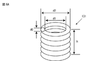
図6A、図6B及び図6Cを参照して、本願の発明者が試作したガス吸収部材131の形状の例を説明する。図6Aに示す例では、ガス吸収部材131はコイル形状である。コイルの軸線方向の長さをh、内径をd1、外径をd2、コイルの線径をd0とする。d0=0.3〜0.5mmである。コイルの内径d1は、リード線121の外径D0より、0.1〜0.2mm大きい。リード線121の外径D0をD0=0.8〜0.9mmとすると、d1=2.1〜0.9mmである。コイルの巻き数は3〜5であってよい。
With reference to FIG. 6A, FIG. 6B, and FIG. 6C, the example of the shape of the
図6Bに示す例では、ガス吸収部材131は円筒形状である。円筒の軸線方向の長さをh、内径をd1、外径をd2、厚さをt1とする。内径d1は、図6Aに示すコイルの内径d1に等しくてよい。厚さt1は0.1mm以上とする。
In the example shown in FIG. 6B, the
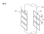
図6Cに示す例では、ガス吸収部材131は1枚又は複数枚の薄板状である。薄板状部材を、リード線121を挟むように、且つ、リード線の軸線に直交する方向に配置する。板状部材の長手方向の寸法をh1、幅方向の寸法をh2、厚さをt1とする。
In the example shown in FIG. 6C, the
図7A及び図7Bを参照して本願の発明者が実施した試験を説明する。本願の発明者は、放電容器130の細管部130Aのリード線121に図6A、図6B及び図6Cに示したガス吸収部材131を装着し、シール装置(図示なし)によって細管部130Aにシール部を形成した。シール装置から放電容器130を取り出し、リード棒の折り曲げ試験を行った。
A test conducted by the inventors of the present application will be described with reference to FIGS. 7A and 7B. The inventor of the present application attaches the
図7Aを参照して、本願の発明者が行ったリード棒の折り曲げ試験の方法を説明する。放電容器130の細管部130Aをクランプ装置(図示なし)によって固定した。細管部130Aより突出したリード線121を左右に略垂直に折り曲げた。リード線121が破損したときの折り曲げ回数を記録した。数え方は、最初に折り曲げた時点で「1回」、次にまっすぐに戻した時点で「2回」とした。
With reference to FIG. 7A, the method of the lead rod bending test performed by the inventors of the present application will be described. The
図7Bは、リード棒の折り曲げ試験の結果を示す。縦軸はリード線121が破損したときの折り曲げ回数である。図において、リード線121が破損したときの折り曲げ回数の平均値μを黒色の四角の点によって表し、バラツキを表すμ±3σ(σは標準偏差)を黒色の四角の点から延びる上下の線の端部によって表す。従来例は、ガス吸収部材131を用いない場合、実施例1は、図6Aに示すコイル形状のガス吸収部材131を用いた場合、実施例2は、図6Bの円筒形状のガス吸収部材131を用いた場合、比較例は、図6Cの薄板状のガス吸収部材131を用いた場合、の結果である。
FIG. 7B shows the results of a lead bar bending test. The vertical axis represents the number of bendings when the
図示のように従来例では、折り曲げ回数が1回でリード線121が破損した。比較例の場合、リード線121が破損したときの折り曲げ回数の平均値は3回以下であった。即ち、折り曲げ回数が1〜3回でリード線121が破損した。実施例1の場合、リード線121が破損したときの折り曲げ回数の平均値は7回であった。即ち、折り曲げ回数が5〜10回でリード線121が破損した。実施例2の場合、リード線121が破損したときの折り曲げ回数の平均値は5回以上であった。即ち、折り曲げ回数が4〜7回でリード線121が破損した。
As shown in the drawing, in the conventional example, the
ランプの製造工程にて、溶接作業等によりリード線121を折り曲げることはあるが、繰り返し折り曲げることはない。従って、本願の発明者は、折り曲げ回数が2回を超えても破損しない場合は合格とした。即ち、破損した時の折り曲げ回数の平均値が3回以上であり、且つ、そのバラツキの下限μ−3σ(σは標準偏差)が2回となることを合格の条件とした。従って、従来例及び比較例は不合格であるが、実施例1、2は何れも合格である。本願の発明者が行った試験から、ガス吸収部材131を用いることによってリード線121が破損し難くなることが判る。更に、ガス吸収部材131の形状は任意であるが、コイル状が最も好ましいことが判る。コイル状のガス吸収部材131の場合、リード線121に対して最適な寸法のコイルを用意することが容易であり、且つ、溶融したフリットとの接触面積が比較的大きい。
In the lamp manufacturing process, the
以上、本実施形態に係るセラミックメタルハライドランプについて説明したが、これらは例示であって、本発明の範囲を制限するものではない。当業者が、本実施形態に対して容易になしえる追加・削除・変更・改良等は、本発明の範囲内である。本発明の技術的範囲は、添付の特許請求の記載によって定められる。 The ceramic metal halide lamp according to the present embodiment has been described above, but these are examples and do not limit the scope of the present invention. Additions, deletions, changes, improvements, and the like that can be easily made by those skilled in the art to the present embodiment are within the scope of the present invention. The technical scope of the present invention is defined by the appended claims.
100…セラミックメタルハライドランプ、108…透光性スリーブ、109…フレーム、110…始動器、111…透光性外管、112…口金、113…ゲッタ、114…マウント支持板、115…ステム、120a、120b…電極システム、121…リード線、121a…ストッパ、122…電流供給導体、122a…耐ハロゲン性中間材、122b…導電性サーメット棒、122c…モリブデン棒、122d…モリブデンコイル、123…タングステン電極、130…放電容器、130A、130B…細管部、130C…発光部、131…ガス吸収部材、132…フリット成形体、135…封止材
DESCRIPTION OF
Claims (6)
前記電流供給導体と前記リード線の接続部分は前記細管部の内部に配置され、前記リード線の一部は前記細管部内に配置され、前記リード線の残りの部分は前記細管部の先端より突出しており、該突出部分の前記細管部近傍の周囲には、前記細管部にシール部を形成するときに発生するガスを吸収するガス吸収部材が装着されており、
前記リード線には、前記ガス吸収部材と前記細管部の先端とを隔離するストッパが接続されていることを特徴とするセラミックメタルハライドランプ。 A translucent outer tube, a discharge vessel having a light emitting portion and a thin tube portion, and an electrode system mounted on the thin tube portion of the discharge vessel, the electrode system comprising a tungsten electrode, a current supply conductor, and In ceramic metal halide lamps configured to have niobium lead wires,
The connecting portion between the current supply conductor and the lead wire is disposed inside the narrow tube portion, a part of the lead wire is disposed within the thin tube portion, and the remaining portion of the lead wire protrudes from the tip of the thin tube portion. A gas absorbing member that absorbs a gas generated when a seal portion is formed in the narrow tube portion is mounted around the vicinity of the narrow tube portion of the protruding portion ;
The lead wire is connected to a stopper for isolating the gas absorbing member and the tip of the narrow tube portion .
前記ガス吸収部材はニオブ製又はタンタル製のコイルによって構成されていることを特徴とするセラミックメタルハライドランプ。 The ceramic metal halide lamp according to claim 1,
The ceramic metal halide lamp, wherein the gas absorbing member is constituted by a coil made of niobium or tantalum.
前記電流供給導体は、耐ハロゲン性中間材と導電性サーメット棒を含み、前記タングステン電極は前記耐ハロゲン性中間材に接続され、前記リード線は前記導電性サーメット棒に接続されていることを特徴とするセラミックメタルハライドランプ。 The ceramic metal halide lamp according to claim 1,
The current supply conductor includes a halogen-resistant intermediate material and a conductive cermet rod, the tungsten electrode is connected to the halogen-resistant intermediate material, and the lead wire is connected to the conductive cermet rod. Ceramic metal halide lamp.
前記細管部のうち封止材が形成されたシール部の長さは、前記細管部の先端から前記導電性サーメット棒の内端までの寸法に等しいか又はそれより大きいことを特徴とするセラミックメタルハライドランプ。 The ceramic metal halide lamp according to claim 3,
The length of the seal part in which the sealing material is formed in the narrow tube part is equal to or larger than the dimension from the tip of the narrow tube part to the inner end of the conductive cermet rod. lamp.
発光部と細管部を有する放電容器と、ニオブ製のリード線を有し、前記リード線には該リード線の軸線に対して直交するように配置された2本の金属線のストッパが接続されている電極システムと、を用意するステップと、
前記電極システムのリード線に、ガス吸収部材を装着し、次に、フリット成形体を装着するステップと、
前記細管部に前記電極システムを挿入するステップと、
前記放電容器の中心軸線が垂直となるように、前記放電容器を支持することにより前記ストッパと前記細管部の端面とを当接させるとともに前記ストッパと前記ガス吸収部材とを当接させるステップと、
前記フリット成形体を加熱して溶融させる溶融ステップと、
前記溶融したフリットが前記ガス吸収部材と接触しながら前記ストッパの間から前記細管部内に流入し、前記細管部の内面と前記電極システムの間の隙間を充填したとき前記溶融したフリットを固化させて封止材を形成するステップと、
を有するセラミックメタルハライドランプの製造方法。 A translucent outer tube, a discharge vessel having a light emitting portion and a thin tube portion, a tungsten electrode provided in the thin tube portion, a current supply conductor, and a lead wire made of niobium, and the lead wire includes the lead In a method of manufacturing a ceramic metal halide lamp, comprising: an electrode system to which two metal wire stoppers arranged so as to be orthogonal to the axis of the wire are connected;
A discharge vessel having a light emitting portion and a thin tube portion, and a lead wire made of niobium, to which two metal wire stoppers arranged so as to be orthogonal to the axis of the lead wire are connected. An electrode system comprising:
Attaching a gas absorbing member to the lead wire of the electrode system, and then attaching a frit molded body;
Inserting the electrode system into the capillary section;
Supporting the discharge vessel so that the central axis of the discharge vessel is vertical, abutting the stopper and the end surface of the narrow tube portion, and abutting the stopper and the gas absorbing member;
A melting step of heating and melting the frit molded body;
The molten frit flows into the narrow tube portion from between the stoppers while contacting the gas absorbing member, and when the gap between the inner surface of the thin tube portion and the electrode system is filled, the molten frit is solidified. Forming a sealing material;
A method of manufacturing a ceramic metal halide lamp having
前記ガス吸収部材はニオブ製又はタンタル製のコイルによって構成されていることを特徴とするセラミックメタルハライドランプの製造方法。 In the manufacturing method of the ceramic metal halide lamp of Claim 5 ,
The method for producing a ceramic metal halide lamp, wherein the gas absorbing member is constituted by a coil made of niobium or tantalum.
Priority Applications (2)
| Application Number | Priority Date | Filing Date | Title |
|---|---|---|---|
| JP2013245462A JP5846504B2 (en) | 2013-11-27 | 2013-11-27 | Ceramic metal halide lamp and manufacturing method thereof |
| PCT/JP2014/076833 WO2015079806A1 (en) | 2013-11-27 | 2014-10-07 | Ceramic metal halide lamp and production method therefor |
Applications Claiming Priority (1)
| Application Number | Priority Date | Filing Date | Title |
|---|---|---|---|
| JP2013245462A JP5846504B2 (en) | 2013-11-27 | 2013-11-27 | Ceramic metal halide lamp and manufacturing method thereof |
Publications (3)
| Publication Number | Publication Date |
|---|---|
| JP2015103491A JP2015103491A (en) | 2015-06-04 |
| JP2015103491A5 JP2015103491A5 (en) | 2015-11-05 |
| JP5846504B2 true JP5846504B2 (en) | 2016-01-20 |
Family
ID=53198760
Family Applications (1)
| Application Number | Title | Priority Date | Filing Date |
|---|---|---|---|
| JP2013245462A Expired - Fee Related JP5846504B2 (en) | 2013-11-27 | 2013-11-27 | Ceramic metal halide lamp and manufacturing method thereof |
Country Status (2)
| Country | Link |
|---|---|
| JP (1) | JP5846504B2 (en) |
| WO (1) | WO2015079806A1 (en) |
Families Citing this family (1)
| Publication number | Priority date | Publication date | Assignee | Title |
|---|---|---|---|---|
| CN115002947B (en) * | 2022-08-04 | 2022-11-04 | 西安交通大学 | Modularized heating device and method for aerospace plane thermal environment simulation |
Family Cites Families (5)
| Publication number | Priority date | Publication date | Assignee | Title |
|---|---|---|---|---|
| NL7612120A (en) * | 1976-11-02 | 1978-05-05 | Philips Nv | ELECTRIC GAS DISCHARGE LAMP. |
| WO2001082331A1 (en) * | 2000-04-19 | 2001-11-01 | Koninklijke Philips Electronics N.V. | High-pressure discharge lamp |
| JP2002367564A (en) * | 2001-06-05 | 2002-12-20 | Iwasaki Electric Co Ltd | Arc tube for metal vapor discharge lamp and its electrode system |
| JP4892807B2 (en) * | 2001-09-26 | 2012-03-07 | 岩崎電気株式会社 | Metal vapor discharge lamp and manufacturing method thereof |
| EP1506566A1 (en) * | 2002-05-10 | 2005-02-16 | Koninklijke Philips Electronics N.V. | Seal for a discharge lamp |
-
2013
- 2013-11-27 JP JP2013245462A patent/JP5846504B2/en not_active Expired - Fee Related
-
2014
- 2014-10-07 WO PCT/JP2014/076833 patent/WO2015079806A1/en active Application Filing
Also Published As
| Publication number | Publication date |
|---|---|
| WO2015079806A1 (en) | 2015-06-04 |
| JP2015103491A (en) | 2015-06-04 |
Similar Documents
| Publication | Publication Date | Title |
|---|---|---|
| US6882109B2 (en) | Electric discharge lamp | |
| US20060279218A1 (en) | High-pressure discharge lamp, high-pressure discharge lamp operating apparatus, and illuminating apparatus | |
| CA2241698A1 (en) | Metal-halide lamp with ceramic discharge vessel | |
| CN1407597A (en) | High-voltage discharge lamp and its manufacture | |
| JP2008527677A (en) | High pressure discharge lamp | |
| JP5846504B2 (en) | Ceramic metal halide lamp and manufacturing method thereof | |
| WO2000024039A1 (en) | Lamp and lamp package made of functionally gradient material | |
| EP3861253B1 (en) | Linear led light source and manufacturing method | |
| EP1053564B1 (en) | Electric lamp | |
| JP4510670B2 (en) | High pressure discharge lamp | |
| JP2006019303A (en) | Metal halide lamp | |
| EP1671188A2 (en) | Discharge lamp | |
| JP2007052973A (en) | Ceramic lamp | |
| JP2009140703A (en) | High-pressure discharge lamp and lighting fixture | |
| JP4498940B2 (en) | Metal halide lamp | |
| EP1465239A2 (en) | Metal vapour discharge lamp | |
| JP4878984B2 (en) | Discharge lamp and discharge lamp manufacturing method | |
| JPH11213952A (en) | Metal halide discharge lamp and lighting system | |
| JP2017220340A (en) | Ceramic metal halide lamp and its manufacturing method | |
| JP2007134330A (en) | Metal halide arc discharge lamp | |
| JP2007073200A (en) | High-pressure discharge lamp | |
| JP2008269956A (en) | Discharge lamp | |
| JP4385495B2 (en) | High pressure discharge lamp | |
| US20090153054A1 (en) | Electric discharge lamp | |
| JP3137602U (en) | Cold cathode discharge tube and electrode assembly for cold cathode discharge tube |
Legal Events
| Date | Code | Title | Description |
|---|---|---|---|
| A521 | Written amendment |
Free format text: JAPANESE INTERMEDIATE CODE: A523 Effective date: 20150911 |
|
| A621 | Written request for application examination |
Free format text: JAPANESE INTERMEDIATE CODE: A621 Effective date: 20150911 |
|
| A871 | Explanation of circumstances concerning accelerated examination |
Free format text: JAPANESE INTERMEDIATE CODE: A871 Effective date: 20150911 |
|
| TRDD | Decision of grant or rejection written | ||
| A975 | Report on accelerated examination |
Free format text: JAPANESE INTERMEDIATE CODE: A971005 Effective date: 20151028 |
|
| A01 | Written decision to grant a patent or to grant a registration (utility model) |
Free format text: JAPANESE INTERMEDIATE CODE: A01 Effective date: 20151030 |
|
| A61 | First payment of annual fees (during grant procedure) |
Free format text: JAPANESE INTERMEDIATE CODE: A61 Effective date: 20151112 |
|
| R150 | Certificate of patent or registration of utility model |
Ref document number: 5846504 Country of ref document: JP Free format text: JAPANESE INTERMEDIATE CODE: R150 |
|
| S531 | Written request for registration of change of domicile |
Free format text: JAPANESE INTERMEDIATE CODE: R313531 |
|
| R350 | Written notification of registration of transfer |
Free format text: JAPANESE INTERMEDIATE CODE: R350 |
|
| LAPS | Cancellation because of no payment of annual fees |