JP5845023B2 - FOCUS DETECTION DEVICE, LENS DEVICE HAVING THE SAME, AND IMAGING DEVICE - Google Patents
FOCUS DETECTION DEVICE, LENS DEVICE HAVING THE SAME, AND IMAGING DEVICE Download PDFInfo
- Publication number
- JP5845023B2 JP5845023B2 JP2011172763A JP2011172763A JP5845023B2 JP 5845023 B2 JP5845023 B2 JP 5845023B2 JP 2011172763 A JP2011172763 A JP 2011172763A JP 2011172763 A JP2011172763 A JP 2011172763A JP 5845023 B2 JP5845023 B2 JP 5845023B2
- Authority
- JP
- Japan
- Prior art keywords
- focus
- image
- correlation
- lens
- pair
- Prior art date
- Legal status (The legal status is an assumption and is not a legal conclusion. Google has not performed a legal analysis and makes no representation as to the accuracy of the status listed.)
- Expired - Fee Related
Links
Images


Classifications
-
- G—PHYSICS
- G02—OPTICS
- G02B—OPTICAL ELEMENTS, SYSTEMS OR APPARATUS
- G02B7/00—Mountings, adjusting means, or light-tight connections, for optical elements
- G02B7/28—Systems for automatic generation of focusing signals
- G02B7/36—Systems for automatic generation of focusing signals using image sharpness techniques, e.g. image processing techniques for generating autofocus signals
-
- H—ELECTRICITY
- H04—ELECTRIC COMMUNICATION TECHNIQUE
- H04N—PICTORIAL COMMUNICATION, e.g. TELEVISION
- H04N23/00—Cameras or camera modules comprising electronic image sensors; Control thereof
- H04N23/60—Control of cameras or camera modules
- H04N23/67—Focus control based on electronic image sensor signals
- H04N23/672—Focus control based on electronic image sensor signals based on the phase difference signals
-
- G—PHYSICS
- G03—PHOTOGRAPHY; CINEMATOGRAPHY; ANALOGOUS TECHNIQUES USING WAVES OTHER THAN OPTICAL WAVES; ELECTROGRAPHY; HOLOGRAPHY
- G03B—APPARATUS OR ARRANGEMENTS FOR TAKING PHOTOGRAPHS OR FOR PROJECTING OR VIEWING THEM; APPARATUS OR ARRANGEMENTS EMPLOYING ANALOGOUS TECHNIQUES USING WAVES OTHER THAN OPTICAL WAVES; ACCESSORIES THEREFOR
- G03B13/00—Viewfinders; Focusing aids for cameras; Means for focusing for cameras; Autofocus systems for cameras
- G03B13/32—Means for focusing
- G03B13/34—Power focusing
- G03B13/36—Autofocus systems
Landscapes
- Physics & Mathematics (AREA)
- Engineering & Computer Science (AREA)
- General Physics & Mathematics (AREA)
- Computer Vision & Pattern Recognition (AREA)
- Optics & Photonics (AREA)
- Multimedia (AREA)
- Signal Processing (AREA)
- Focusing (AREA)
- Automatic Focus Adjustment (AREA)
- Studio Devices (AREA)
Description
本発明は、テレビレンズやビデオレンズ等の光学機器に関し、特にオートフォーカス機能のための焦点検出装置及びそれを有するレンズ装置及び撮像装置に関するものである。 The present invention relates to an optical device such as a television lens and a video lens, and more particularly to a focus detection device for an autofocus function, a lens device having the focus detection device, and an imaging device.
従来、カメラやビデオカメラ等の撮影装置におけるオートフォーカス(AF)技術として様々な提案が成されている。例えば、撮影レンズの異なる射出瞳領域を通過した被写体からの光束を、一対のラインセンサ上に結像させ、被写体像を光電変換して得られた一対の像信号の相対位置変位量を求める。この変位量を元に被写体のデフォーカス量を算出し、撮影レンズの駆動を行う自動焦点調整方法が良く知られている。
この位相差検出によるAF方式は被写体距離からフォーカスレンズの合焦位置を求めることが出来るので、コントラストAFに比べて高速で合焦が得られる特徴がある。
Conventionally, various proposals have been made as an autofocus (AF) technique in a photographing apparatus such as a camera or a video camera. For example, a light flux from a subject that has passed through different exit pupil regions of the photographing lens is imaged on a pair of line sensors, and a relative position displacement amount of a pair of image signals obtained by photoelectrically converting the subject image is obtained. An automatic focus adjustment method for calculating a defocus amount of a subject based on this displacement amount and driving a photographing lens is well known.
The AF method based on this phase difference detection has a feature that the focus position of the focus lens can be obtained from the subject distance, so that the focus can be obtained at a higher speed than the contrast AF.
特許文献1には、位相差検出方式による焦点検出ができない場合にフォーカスレンズを駆動しながらフォーカスのずれを検出するスキャンAFに自動的に移行してしまう可能性を低減するため、通常の位相差検出に使用される2つのラインセンサ上の相関演算の対象とする画素数を削減して相関演算に供する画素シフト量を拡大し焦点検出のデフォーカス範囲を広くする手法が開示されている。
In
しかしながら、特許文献1では焦点検出のデフォーカス範囲を広くすることは出来るが、相関演算の対象とする画素数を削減することにより検出精度が劣化することに加え、AFセンサ上に複数の異なる被写体距離の被写体が存在する場合には、誤検出を生じ易くなる。また、少ない画素数間での相関演算によって大デフォーカス量での焦点検出を実施して検出するデフォーカス範囲を拡大するため、AFセンサ上に複数の被写体距離が存在するときには、誤検出を生じ易いという課題を有する。
However, although
上記目的を達成するために、本発明の焦点検出装置は、一対のレンズと、前記一対のレンズにより結像される一対の被写体像を一対の像信号に光電変換する、複数の画素を有するセンサと、演算対象画素数が変化させられた状態ごとに、前記一対の像信号に対して相関量を演算すると共に、前記状態ごとに演算された相関量に基づく一致度が高い演算対象画素数の中から、最も少ない演算対象画素数に基づき基準画素数を設定する設定手段と、前記基準画素数に基づき規定された前記センサの複数の領域ごとに、前記一対の像信号に対して相関量を演算する相関演算手段と、前記相関演算手段により演算された相関量に基づいて選択された像ズレ量によりデフォーカス量を演算するデフォーカス量演算手段と、を有することを特徴とする。
To achieve the above object, a focus detection apparatus according to the present invention includes a pair of lenses and a sensor having a plurality of pixels that photoelectrically converts a pair of subject images formed by the pair of lenses into a pair of image signals. For each state in which the number of calculation target pixels is changed, the correlation amount is calculated for the pair of image signals, and the number of calculation target pixels having a high degree of coincidence based on the correlation amount calculated for each state. A setting unit that sets a reference pixel number based on the smallest number of calculation target pixels, and a correlation amount for the pair of image signals for each of a plurality of regions of the sensor defined based on the reference pixel number. correlation computing means for computing, and having a defocus amount calculation means for calculating a defocus amount by the image shift amount that has been chosen based on the calculated correlation amount by the correlation calculation means.
本発明によれば、AF対象となるセンサ上に複数の異なる被写体距離の被写体が存在したときにも、正確な測距結果が得られ、合焦検出精度向上とデフォーカス範囲拡大を両立出来る焦点検出装置を提供することが出来る。 According to the present invention, even when there are a plurality of subjects with different subject distances on a sensor to be an AF target, an accurate distance measurement result can be obtained, and a focus that can achieve both improvement in focus detection accuracy and expansion of the defocus range. A detection device can be provided.
以下に、本発明の好ましい実施の形態を、添付の図面に基づいて詳細に説明する。 Hereinafter, preferred embodiments of the present invention will be described in detail with reference to the accompanying drawings.
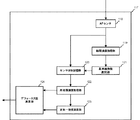
図1は本発明の自動焦点調整装置を実装したズームレンズ装置100の構成図である。
ズームレンズ装置100は、フォーカスレンズ101、ズームレンズ105、可動絞り109、分光プリズム113、リレーレンズ114を含む撮像光学系を有する。フォーカスレンズ101は、フォーカス駆動手段であるフォーカスモータ102によって光軸方向に駆動され、ズームレンズ装置100の結像面の位置を光軸方向に変化させる。フォーカスモータ102は、フォーカスドライバ103によって駆動される。フォーカスレンズ101の位置は、フォーカス位置検出部104によって検出される。
FIG. 1 is a configuration diagram of a
The
ズームレンズ105は、ズームモータ106によって光軸方向に駆動され、ズームレンズ装置100の焦点距離を変化させる。ズームモータ106は、ズームドライバ107によって駆動される。ズームレンズ105の位置は、ズーム位置検出部108によって検出される。
The
可動絞り109は、アイリスドライバ111によって駆動されるアイリスモータ110によって駆動する。可動絞り109の位置は、アイリス位置検出部112によって検出される。
The movable diaphragm 109 is driven by an iris motor 110 driven by an
分光プリズム113は、フォーカスレンズ101とズームレンズ105を通過した被写体光を透過光と反射光に分離する。分光プリズム113を透過した光束(透過光)は、リレーレンズ114を通って当該ズームレンズ装置が接続されたカメラ装置等の撮像素子115に入射する。また、分光プリズム113で反射された光束(反射光)は、焦点検出部117に入射する。焦点検出部117は、一対の像信号の位相差を算出しデフォーカス量を算出する。レンズ制御部116は、焦点検出部117で得られた位相差を基に、フォーカスレンズ101を駆動すると共に、ズームレンズ105、可動絞り109を制御する。
The spectroscopic prism 113 separates the subject light that has passed through the
図2は焦点検出部117の構成を示す。分光プリズム113で反射された反射光はAFセンサ118に入射する。AFセンサ118は、一対の位相差検出レンズと一対の位相差検出センサで構成される。一対の瞳領域を通過し、位相差検出レンズによって分割された2つの光束により形成された一対の像(2像)は、位相差検出センサにて光電変換され、像信号を生成する。位相差検出センサに電荷として蓄積された2像の信号(輝度信号)は読み出され、相関演算処理部119(設定手段)に供給されるとともに、センサ波形記憶部120に記憶される。
FIG. 2 shows the configuration of the
以下、本発明の自動焦点調整装置におけるデフォーカス量を演算する手順について、以下、図3に示したフローチャートを参照しながら説明を進める。
図4に示す一対のセンサ波形(A像、B像)が相関演算処理部119へ供給された場合を例示して説明する。図4は、一対のセンサ波形を重ねて表示したものである。図4の2像センサ波形では2つの異なる被写体距離が存在していることを示す。相関演算処理部119では、図5(a)に示す様に一対のセンサ画素の同一位置(破線部の画素間)にて相関演算を施す(図3のステップS301)。その時の一対のセンサ波形であるA像およびB像をそれぞれ図5(b)および図5(c)に示す。
The procedure for calculating the defocus amount in the automatic focus adjustment apparatus of the present invention will be described below with reference to the flowchart shown in FIG.
A case where the pair of sensor waveforms (A image, B image) shown in FIG. 4 is supplied to the correlation
ここで、相関演算とは、A像とB像の対応する画素データの差の絶対値を、A像とB像を比較する画素範囲の全体に渡っての和として得られる相関値CORを得る演算であり、以下の(1)式のように得られるものである。
![]()
![]()
次に、A像のセンサ画素位置を固定し、B像のセンサ波形を1画素ずつ左にシフト して、A像とB像で対応する画素がある部分において同様に相関演算を施す。このとき、図6(a)において左側から右側の順に画素を1、2、・・・と番号付けすると、B像の波形をk画素だけ左に移動した場合には、全画素の数をnとすると、A1〜An−kとBi+k〜Bnとをそれぞれ比較して(1a)式で相関量COR(k) (k≧0)を算出することになる。

次に、A像のセンサ画素位置を固定し、B像のセンサ波形を1画素ずつ右にシフトして同様に相関演算を施す。この場合にも、B像の波形をk画素だけ右に移動し、Ai+k〜AnとB1〜Bn−kとをそれぞれ比較して相関量を算出する。B像のセンサ波形を左にシフトした場合のシフト数を正、右にシフトした場合のシフト数を負、とすると、この場合の相関量COR(k)(k≦0)は、(1b)式で表される。
全ての相関演算処理が終了すると、(2)式によって、k画素シフトしたときの相関量COR(k)と、k+1画素シフトしたときの相関量COR(k+1)から、k画素シフトしたときの2像の相関量差ΔCOR(k)を算出する(図3のステップS302)。
![]()
![]()
相関量COR(k)が0であると、そのシフト量kおよびそのときの相関演算の対象とした画素範囲において、A像とB像は完全に一致し、像ズレはない。相関量差ΔCOR(k)を評価することにより、相関量COR(k)が減少から増加に変化する位置を、相関量差ΔCOR(k)が負から正の値に変化して0を横切る画素シフト量k(以下、ゼロクロス点とも記す)によって、合焦候補点として得ることができる。図8に相関量差ΔCOR(k)を示すように、2像の相関量差ΔCOR(k)のゼロクロス点の画素シフト量kを合焦候補点のデフォーカス候補値として選択することができる(図3のステップS303)。 When the correlation amount COR (k) is 0, the A image and the B image completely coincide with each other in the shift amount k and the pixel range subjected to the correlation calculation at that time, and there is no image shift. By evaluating the correlation amount difference ΔCOR (k), the position where the correlation amount COR (k) changes from decrease to increase, and the pixel where the correlation amount difference ΔCOR (k) changes from negative to positive and crosses zero It can be obtained as a focus candidate point by the shift amount k (hereinafter also referred to as zero cross point). As shown in FIG. 8, the correlation amount difference ΔCOR (k) can select the pixel shift amount k at the zero cross point of the correlation amount difference ΔCOR (k) between the two images as the defocus candidate value of the in-focus candidate point ( Step S303 in FIG.
2像の波形一致度を下記(3)式のMin_COR(k)及び(4)式のMax_COR(k)により、図9のように示す。
![]()
![]()
![]()
![]()
図8に示した各画素シフト量における2像の相関量差ΔCOR(k)が負から正の値に変化して0を横切る点である画素シフト量(図8中に示した画素シフト量A,B,C,D)(像ズレ量)における2像波形一致度(図9中に示した画素シフト量A,B,C,Dでの波形一致度)を比較する。ここで、波形一致度であるMin_COR(k)とMax_COR(k)の差が一番小さい値となる画素シフト量(A及びB)を合焦点として選択すると、図6(a)及び7(a)に示した画素シフト量が選択される。しかし、これは、異なる一対の位相差検出センサ上の互いに異なる被写体像に対する相関演算の結果であり、相関演算の対象とする画素数が少ないことに起因する誤検出である。本発明においては、この相関演算の対象とする画素数が少ないことに起因する誤検出を回避するため、図3のステップS303で求められた合焦候補点のデフォーカス候補値から、直接、2像波形一致度を評価して合焦候補点のデフォーカス量を求めず、以下に説明する、ステップS304〜S307の処理によって合焦候補点を求める。 The pixel shift amount (pixel shift amount A shown in FIG. 8) is the point where the correlation amount difference ΔCOR (k) between the two images at each pixel shift amount shown in FIG. , B, C, D) (image shift amount), the two image waveform matching degrees (waveform matching degrees at pixel shift amounts A, B, C, D shown in FIG. 9) are compared. Here, when the pixel shift amount (A and B) at which the difference between Min_COR (k) and Max_COR (k), which are the waveform matching degrees, is the smallest value is selected as the focal point, FIGS. ) Is selected. However, this is a result of correlation calculation for different subject images on different pairs of phase difference detection sensors, and is a false detection due to the small number of pixels to be subjected to correlation calculation. In the present invention, in order to avoid erroneous detection due to the small number of pixels to be subjected to the correlation calculation, the direct defocus candidate value obtained in step S303 in FIG. The focus candidate point is obtained by the processing of steps S304 to S307 described below without evaluating the degree of coincidence of the image waveforms and obtaining the defocus amount of the focus candidate point.
本発明においては、相関演算処理部119にて算出された1つ以上の画素シフト量の候補値(図8中に示した画素シフト量A,B,C,D)における相関演算対象の画素数(相関演算画素数)が、基準画素数選択部121(設定手段)に送られる。基準画素数選択部121は、供給された相関演算画素数のうち、一番少ない画素数を再相関演算のための基準画素数として選択する(図3のステップS304)と共に、センサ波形記憶部120に記憶された2像の輝度波形信号を読出し、再相関演算処理部122(相関演算手段)に供給する。ここで例示した波形においては、合焦候補点である画素シフト量A,B,C,Dの中で、画素シフト量Aで相関演算をしたときの、相関演算の対象とした画素数が最も少ない画素数なので、これが再相関演算のための基準画素数として選択される。
再相関演算処理部122は、センサ波形記憶部120から読み出された2像の波形信号を、基準画素数となるように分割し(図3のステップS305)、分割されたそれぞれの領域に対して再度、同様の相関演算(再相関演算)を施す(図3のステップS306)。
In the present invention, the number of pixels subject to correlation calculation in one or more candidate pixel shift amount values (pixel shift amounts A, B, C, and D shown in FIG. 8) calculated by the correlation
The recorrelation calculation processing unit 122 divides the two image waveform signals read from the sensor
分割された2像センサ波形を領域ごとに、図10、11、12に示す。
図10(a)は一対のセンサ画素の同一位置の左側領域の画素の分割領域(破線部の画素間)を示し、図10(b)および図10(c)に2像のセンサ波形を表している。
図11(a)は一対のセンサ画素の同一位置の中心領域の画素の分割領域(破線部の画素間)を示し、図11(b)および図11(c)に2像のセンサ波形を表している。
図12(a)は一対のセンサ画素の同一位置の右端領域の画素の分割領域(破線部の画素間)を示し、図12(b)および図12(c)に2像のセンサ波形を表している。
The divided two-image sensor waveforms are shown in FIGS. 10, 11, and 12 for each region.
10 (a) shows a divided area (between the dashed line portion of pixels) of the pixels of the left area of the same position of the pair of sensor pixels, the sensor waveform of two images in FIGS. 10 (b) and 10 (c) Represents.
11 (a) shows a divided region of the pixel of the central region of the same position of the pair of sensor pixel (between pixels of the broken line portion), the sensor waveform of two images in FIG. 11 (b) and FIG. 11 (c) Represents.
12 (a) is shown the divided region of the pixel at the right end region of the same position of the pair of sensor pixel (between pixels of the broken line portion), the sensor waveform of two images in FIG. 12 (b) and FIG. 12 (c) Represents.
図10(a)、11(a)、12(a)に示した演算対象画素の領域に対して夫々、(2)式より、2像の相関量差ΔCOR(k)を画素シフト量kに対して演算する(図3のステップS307)。相関量差ΔCOR(k)は、相関演算の対象とする画素数が、前記所定の相関演算対象画素数より少なくならない範囲において、A像とB像を相対的にシフトさせて行う。ここでもステップS303と同様に、相関量差ΔCOR(k)を評価することにより、相関量COR(k)が減少から増加に変化する位置を、相関量差ΔCOR(k)のゼロクロス点の画素シフト量kにおいて合焦候補点として認識することができる(図3のステップS307)。 The correlation amount difference ΔCOR (k) between the two images is set to the pixel shift amount k from the equation (2) for the calculation target pixel regions shown in FIGS. 10 (a), 11 (a), and 12 (a). On the other hand, the calculation is performed (step S307 in FIG. 3). The correlation amount difference ΔCOR (k) is obtained by relatively shifting the A image and the B image in a range where the number of pixels targeted for correlation calculation is not less than the predetermined number of correlation calculation target pixels. Here, as in step S303, by evaluating the correlation amount difference ΔCOR (k), the pixel shift of the zero cross point of the correlation amount difference ΔCOR (k) is changed to the position where the correlation amount COR (k) changes from decrease to increase. The amount k can be recognized as a focus candidate point (step S307 in FIG. 3).
図11(a)に示したA像とB像の中心を含む画素の分割領域に対する相関演算においては、相関量差ΔCOR(k)のゼロクロス点が存在しないためこの画素領域には合焦対象となる被写体像がないと判断される。
波形一致度演算部123は、再相関演算処理部122での各分割領域に対する相関演算によりゼロクロス点の存在が確認された領域に対して、(3)(4)式によって波形一致度を算出する。本実施例においては、図10(a)の左側領域に対しては図13のように、図12(a)の右側領域に対しては図14のように波形一致度が演算される(図3のステップS308)。
In the correlation calculation for the divided region of the pixel including the centers of the A image and the B image shown in FIG. 11A, there is no zero cross point of the correlation amount difference ΔCOR (k). It is determined that there is no subject image.
The waveform coincidence
この算出結果から波形一致度Min_CORとMax_CORの差分が一番小さい値となる画素シフト量を選択するため、図13または図14で特定される画素シフト量が合焦候補点の画素シフト量として選択される(図3のステップS309)。
デフォーカス量演算部124では再相関演算処理部122にて算出された画素シフト量の各候補値から波形一致度演算部123にて最も波形一致度の高い画素シフト量(図13および図14に対応する画素シフト量B及びC)が選択され、デフォーカス値に変換される(図3のステップS310)。
From this calculation result, in order to select a pixel shift amount in which the difference between the waveform coincidence Min_COR and Max_COR is the smallest value, the pixel shift amount specified in FIG. 13 or 14 is selected as the pixel shift amount of the focus candidate point. (Step S309 in FIG. 3).
In the defocus
以上、説明したとおり本実施例によれば、AF対象となるセンサ上に複数の被写体距離が存在したときにも、正確な測距結果が得られ、合焦検出精度向上とデフォーカス範囲拡大を両立出来る焦点検出結果を得ることが出来る。 As described above, according to the present embodiment, accurate distance measurement results can be obtained even when there are a plurality of subject distances on the sensor to be AF target, and the focus detection accuracy can be improved and the defocus range can be expanded. A compatible focus detection result can be obtained.
特に、動画を撮影している場合、ある時点において合焦している被写体からかけ離れた物体距離の被写体に対してフォーカスを移動させる頻度は低く、その時点で合焦している被写体またはそれに近い物体距離の被写体に合焦させるオーフォーカス動作がより高い頻度で求められる。従って、本発明による構成によって、カメラ操作者に対して、適切な合焦候補点を精度よく提示することによって、好適なオートフォーカス動作環境を実現することができる。
本発明の好ましい実施形態について説明したが、本発明はこれらの実施形態に限定されず、その要旨の範囲内で種々の変形及び変更が可能である。
In particular, when shooting a video, the focus is less frequently moved to a subject at an object distance far away from the subject that is in focus at a certain time, and the subject that is in focus at that time or an object close to it An autofocus operation for focusing on an object at a distance is required more frequently. Therefore, with the configuration according to the present invention, a suitable autofocus operation environment can be realized by accurately presenting appropriate focus candidate points to the camera operator.
Although preferable embodiment of this invention was described, this invention is not limited to these embodiment, A various deformation | transformation and change are possible within the range of the summary.
101:フォーカスレンズ
102:フォーカスモータ
103:フォーカスドライバ
104:フォーカス位置検出部
113:分光プリズム
114:リレーレンズ
115:撮像素子
116:レンズ制御部
117:焦点検出部
118:AFセンサ
121:基準画素数選択部
122:再相関演算処理部
123:波形一致度演算部
124:デフォーカス量演算部
101: Focus lens 102: Focus motor 103: Focus driver 104: Focus position detection unit 113: Spectral prism 114: Relay lens 115: Image sensor 116: Lens control unit 117: Focus detection unit 118: AF sensor 121: Reference pixel number selection Unit 122: Recorrelation calculation processing unit 123: Waveform coincidence calculation unit 124: Defocus amount calculation unit
Claims (4)
前記一対のレンズにより結像される一対の被写体像を一対の像信号に光電変換する、複数の画素を有するセンサと、
演算対象画素数が変化させられた状態ごとに、前記一対の像信号に対して相関量を演算すると共に、前記状態ごとに演算された相関量に基づく一致度が高い演算対象画素数の中から、最も少ない演算対象画素数に基づき基準画素数を設定する設定手段と、
前記基準画素数に基づき規定された前記センサの複数の領域ごとに、前記一対の像信号に対して相関量を演算する相関演算手段と、
前記相関演算手段により演算された相関量に基づいて選択された像ズレ量によりデフォーカス量を演算するデフォーカス量演算手段と、
を有することを特徴とする焦点検出装置。 A pair of lenses;
A sensor having a plurality of pixels that photoelectrically converts a pair of subject images formed by the pair of lenses into a pair of image signals;
For each state in which the number of calculation target pixels is changed, the correlation amount is calculated for the pair of image signals, and the degree of coincidence based on the correlation amount calculated for each state is high. Setting means for setting the reference pixel number based on the smallest calculation target pixel number;
Correlation calculation means for calculating a correlation amount for the pair of image signals for each of a plurality of regions of the sensor defined based on the reference pixel number ;
Defocus amount calculation means for calculating a defocus amount based on an image shift amount selected based on the correlation amount calculated by the correlation calculation means ;
Focus detecting apparatus characterized by having a.
前記デフォーカス量演算手段による像ズレ量の選択は、前記相関量と、前記波形一致度演算手段により演算された一致度と、に基づく、
ことを特徴とする請求項1に記載の焦点検出装置。 Before SL has a waveform coincidence degree calculating means for calculating the degree of coincidence between a pair of image signals,
The defocus amount calculation means selecting the image shift amount by, the correlation amount, based rather on the calculated degree of matching by the waveform matching degree calculation means,
Focus detecting apparatus according to claim 1, wherein the this.
前記フォーカスレンズを駆動するフォーカス駆動手段と、
前記フォーカス駆動手段を制御するレンズ制御手段と、
請求項1又は2に記載の焦点検出装置と、
を有し、
前記レンズ制御手段は、前記焦点検出装置により演算されたデフォーカス量に基づき、前記フォーカス駆動手段を制御する、
ことを特徴とするレンズ装置。 An imaging optical system including a focus lens;
Focus drive means for driving the focus lens;
Lens control means for controlling the focus driving means;
The focus detection device according to claim 1 or 2 ,
Have
The lens control unit controls the focus driving unit based on a defocus amount calculated by the focus detection device;
A lens device.
前記フォーカスレンズを駆動するフォーカス駆動手段と、
前記フォーカス駆動手段を制御するレンズ制御手段と、
請求項1又は2に記載の焦点検出装置と、
前記撮像光学系により結像される被写体像を撮像する撮像素子と、
を有し、
前記レンズ制御手段は、前記焦点検出装置により演算されたデフォーカス量に基づき、前記フォーカス駆動手段を制御する、
ことを特徴とする撮像装置。 An imaging optical system including a focus lens;
Focus drive means for driving the focus lens;
Lens control means for controlling the focus driving means;
The focus detection device according to claim 1 or 2 ,
An image sensor for imaging a subject image formed by the imaging optical system;
Have
The lens control unit controls the focus driving unit based on a defocus amount calculated by the focus detection device;
An imaging apparatus characterized by that.
Priority Applications (5)
| Application Number | Priority Date | Filing Date | Title |
|---|---|---|---|
| JP2011172763A JP5845023B2 (en) | 2011-08-08 | 2011-08-08 | FOCUS DETECTION DEVICE, LENS DEVICE HAVING THE SAME, AND IMAGING DEVICE |
| CN201210274495.8A CN102928197B (en) | 2011-08-08 | 2012-08-03 | Focused detector and the lens assembly and the image pick-up device that comprise focused detector |
| US13/568,570 US8848095B2 (en) | 2011-08-08 | 2012-08-07 | Focus detector, and lens apparatus and image pickup apparatus including the same |
| EP12179463.0A EP2557771B1 (en) | 2011-08-08 | 2012-08-07 | Focus detector, and lens apparatus and image pickup apparatus including the same |
| US14/458,404 US9154689B2 (en) | 2011-08-08 | 2014-08-13 | Focus detector, and lens apparatus and image pickup apparatus including the same |
Applications Claiming Priority (1)
| Application Number | Priority Date | Filing Date | Title |
|---|---|---|---|
| JP2011172763A JP5845023B2 (en) | 2011-08-08 | 2011-08-08 | FOCUS DETECTION DEVICE, LENS DEVICE HAVING THE SAME, AND IMAGING DEVICE |
Publications (3)
| Publication Number | Publication Date |
|---|---|
| JP2013037166A JP2013037166A (en) | 2013-02-21 |
| JP2013037166A5 JP2013037166A5 (en) | 2015-02-26 |
| JP5845023B2 true JP5845023B2 (en) | 2016-01-20 |
Family
ID=47002561
Family Applications (1)
| Application Number | Title | Priority Date | Filing Date |
|---|---|---|---|
| JP2011172763A Expired - Fee Related JP5845023B2 (en) | 2011-08-08 | 2011-08-08 | FOCUS DETECTION DEVICE, LENS DEVICE HAVING THE SAME, AND IMAGING DEVICE |
Country Status (4)
| Country | Link |
|---|---|
| US (2) | US8848095B2 (en) |
| EP (1) | EP2557771B1 (en) |
| JP (1) | JP5845023B2 (en) |
| CN (1) | CN102928197B (en) |
Families Citing this family (8)
| Publication number | Priority date | Publication date | Assignee | Title |
|---|---|---|---|---|
| JP5845023B2 (en) * | 2011-08-08 | 2016-01-20 | キヤノン株式会社 | FOCUS DETECTION DEVICE, LENS DEVICE HAVING THE SAME, AND IMAGING DEVICE |
| JP6014452B2 (en) * | 2012-10-16 | 2016-10-25 | キヤノン株式会社 | FOCUS DETECTION DEVICE, LENS DEVICE HAVING THE SAME, AND IMAGING DEVICE |
| JP6334847B2 (en) * | 2013-04-17 | 2018-05-30 | キヤノン株式会社 | FOCUS DETECTION DEVICE, FOCUS DETECTION METHOD AND PROGRAM, AND IMAGING DEVICE |
| JP2015102735A (en) * | 2013-11-26 | 2015-06-04 | 株式会社ニコン | Focus detection device and imaging device |
| JP6916419B2 (en) * | 2013-11-26 | 2021-08-11 | 株式会社ニコン | Focus adjuster |
| JP6320195B2 (en) * | 2014-06-24 | 2018-05-09 | キヤノン株式会社 | IMAGING DEVICE, CONTROL DEVICE, CONTROL METHOD, PROGRAM, AND STORAGE MEDIUM |
| CN105007425B (en) * | 2015-07-23 | 2018-07-06 | 广东欧珀移动通信有限公司 | A kind of contrast formula focusing method and mobile terminal |
| CN105611175B (en) * | 2016-02-29 | 2019-02-05 | Oppo广东移动通信有限公司 | Control method, control device and electronic device |
Family Cites Families (22)
| Publication number | Priority date | Publication date | Assignee | Title |
|---|---|---|---|---|
| JP2614137B2 (en) * | 1990-05-30 | 1997-05-28 | 富士写真フイルム株式会社 | Phase difference detector |
| JPH05257062A (en) * | 1992-03-10 | 1993-10-08 | Canon Inc | Automatic focusing device |
| JP3491343B2 (en) * | 1994-06-29 | 2004-01-26 | 株式会社ニコン | Focus detection device and focus detection method |
| JPH08248303A (en) * | 1995-03-07 | 1996-09-27 | Minolta Co Ltd | Focus detector |
| JPH1026526A (en) * | 1996-07-10 | 1998-01-27 | Fuji Photo Film Co Ltd | Triangulation type range finding method |
| JPH1184227A (en) * | 1997-09-02 | 1999-03-26 | Minolta Co Ltd | Focus position detecting device |
| US6411782B1 (en) * | 1999-05-20 | 2002-06-25 | Olympus Optical Co., Ltd. | Multi-autofocus distance-measuring system with a wide distance-measuring area |
| JP2001141987A (en) * | 1999-11-17 | 2001-05-25 | Olympus Optical Co Ltd | Range finder |
| JP2001174694A (en) * | 1999-12-21 | 2001-06-29 | Olympus Optical Co Ltd | Range-finger |
| US6614509B2 (en) * | 2000-12-15 | 2003-09-02 | Olympus Optical Co., Ltd. | Distance measuring apparatus |
| US6701074B2 (en) * | 2001-12-07 | 2004-03-02 | Fuji Photo Optical Co., Ltd. | Distance measuring apparatus |
| JP4632640B2 (en) * | 2003-08-15 | 2011-02-16 | 富士フイルム株式会社 | Ranging device |
| JP5499432B2 (en) * | 2007-10-05 | 2014-05-21 | ソニー株式会社 | Imaging device |
| JP5451111B2 (en) | 2008-03-11 | 2014-03-26 | キヤノン株式会社 | Focus detection apparatus and imaging apparatus having the same |
| JP2010066712A (en) | 2008-09-12 | 2010-03-25 | Olympus Corp | Focus adjusting device and image pickup apparatus |
| JP5097077B2 (en) | 2008-10-10 | 2012-12-12 | キヤノン株式会社 | Imaging apparatus, control method thereof, and program |
| JP5147645B2 (en) * | 2008-10-30 | 2013-02-20 | キヤノン株式会社 | Imaging device |
| JP5146295B2 (en) | 2008-12-15 | 2013-02-20 | ソニー株式会社 | Imaging apparatus and focus control method |
| JP5470985B2 (en) * | 2009-04-03 | 2014-04-16 | 株式会社ニコン | Focus detection apparatus and imaging apparatus |
| JP2010243753A (en) * | 2009-04-06 | 2010-10-28 | Seiko Epson Corp | Liquid crystal device and electronic device |
| JP5845023B2 (en) * | 2011-08-08 | 2016-01-20 | キヤノン株式会社 | FOCUS DETECTION DEVICE, LENS DEVICE HAVING THE SAME, AND IMAGING DEVICE |
| JP5907595B2 (en) * | 2011-09-27 | 2016-04-26 | キヤノン株式会社 | Imaging device |
-
2011
- 2011-08-08 JP JP2011172763A patent/JP5845023B2/en not_active Expired - Fee Related
-
2012
- 2012-08-03 CN CN201210274495.8A patent/CN102928197B/en not_active Expired - Fee Related
- 2012-08-07 US US13/568,570 patent/US8848095B2/en not_active Expired - Fee Related
- 2012-08-07 EP EP12179463.0A patent/EP2557771B1/en not_active Not-in-force
-
2014
- 2014-08-13 US US14/458,404 patent/US9154689B2/en not_active Expired - Fee Related
Also Published As
| Publication number | Publication date |
|---|---|
| EP2557771B1 (en) | 2017-04-12 |
| US20140347550A1 (en) | 2014-11-27 |
| EP2557771A2 (en) | 2013-02-13 |
| CN102928197B (en) | 2016-01-20 |
| JP2013037166A (en) | 2013-02-21 |
| US8848095B2 (en) | 2014-09-30 |
| US20130038779A1 (en) | 2013-02-14 |
| US9154689B2 (en) | 2015-10-06 |
| CN102928197A (en) | 2013-02-13 |
| EP2557771A3 (en) | 2013-04-24 |
Similar Documents
| Publication | Publication Date | Title |
|---|---|---|
| JP5845023B2 (en) | FOCUS DETECTION DEVICE, LENS DEVICE HAVING THE SAME, AND IMAGING DEVICE | |
| US9411128B2 (en) | Automatic focusing apparatus with cyclic pattern determination | |
| JP4872834B2 (en) | Image recognition device, focus adjustment device, and imaging device | |
| US9444993B2 (en) | Focus detecting apparatus, lens apparatus including the same, image pickup apparatus, and method of detecting defocus amount | |
| US10291840B2 (en) | Focus detection device and image-capturing apparatus | |
| JP2008203294A (en) | Imaging apparatus | |
| JP5618712B2 (en) | Automatic focusing device and imaging device | |
| JP2010015024A (en) | Image pickup apparatus, control method thereof, program and storage medium | |
| JP2015194706A5 (en) | ||
| JP5417827B2 (en) | Focus detection apparatus and imaging apparatus | |
| JP2013037166A5 (en) | ||
| US20200228719A1 (en) | Focus control apparatus, imaging apparatus, focus control method, and storage medium | |
| US10999491B2 (en) | Control apparatus, image capturing apparatus, control method, and storage medium | |
| JP2018148383A (en) | Imaging apparatus and imaging unit | |
| JP6381434B2 (en) | FOCUS CONTROL DEVICE, OPTICAL DEVICE, AND FOCUS CONTROL METHOD | |
| JP5420034B2 (en) | Imaging apparatus, control method therefor, program, and storage medium | |
| JP5930979B2 (en) | Imaging device | |
| JP5541396B2 (en) | Image tracking device | |
| CN108540714B (en) | Image capturing apparatus, image capturing system, image capturing apparatus control method, and storage medium | |
| JP2012242613A (en) | Imaging apparatus and method for controlling the same | |
| JP5347834B2 (en) | Image tracking device | |
| JP2008070428A (en) | Focusing apparatus and camera | |
| JP2018105948A (en) | Focus detection method, and imaging device | |
| JP2019128549A (en) | Focus detector and optical apparatus equipped with focus detector | |
| JP2018033059A (en) | Image processing method, image processing apparatus, image processing program and imaging apparatus |
Legal Events
| Date | Code | Title | Description |
|---|---|---|---|
| RD05 | Notification of revocation of power of attorney |
Free format text: JAPANESE INTERMEDIATE CODE: A7425 Effective date: 20130701 |
|
| A621 | Written request for application examination |
Free format text: JAPANESE INTERMEDIATE CODE: A621 Effective date: 20140807 |
|
| A521 | Request for written amendment filed |
Free format text: JAPANESE INTERMEDIATE CODE: A523 Effective date: 20150106 |
|
| A871 | Explanation of circumstances concerning accelerated examination |
Free format text: JAPANESE INTERMEDIATE CODE: A871 Effective date: 20150106 |
|
| A975 | Report on accelerated examination |
Free format text: JAPANESE INTERMEDIATE CODE: A971005 Effective date: 20150209 |
|
| A131 | Notification of reasons for refusal |
Free format text: JAPANESE INTERMEDIATE CODE: A131 Effective date: 20150303 |
|
| A521 | Request for written amendment filed |
Free format text: JAPANESE INTERMEDIATE CODE: A523 Effective date: 20150507 |
|
| A131 | Notification of reasons for refusal |
Free format text: JAPANESE INTERMEDIATE CODE: A131 Effective date: 20150709 |
|
| A521 | Request for written amendment filed |
Free format text: JAPANESE INTERMEDIATE CODE: A523 Effective date: 20150827 |
|
| TRDD | Decision of grant or rejection written | ||
| A01 | Written decision to grant a patent or to grant a registration (utility model) |
Free format text: JAPANESE INTERMEDIATE CODE: A01 Effective date: 20151022 |
|
| A61 | First payment of annual fees (during grant procedure) |
Free format text: JAPANESE INTERMEDIATE CODE: A61 Effective date: 20151120 |
|
| R151 | Written notification of patent or utility model registration |
Ref document number: 5845023 Country of ref document: JP Free format text: JAPANESE INTERMEDIATE CODE: R151 |
|
| LAPS | Cancellation because of no payment of annual fees |