JP5845003B2 - Vertical axis fluid power generator - Google Patents

Vertical axis fluid power generator Download PDF

Info

Publication number
JP5845003B2
JP5845003B2 JP2011129277A JP2011129277A JP5845003B2 JP 5845003 B2 JP5845003 B2 JP 5845003B2 JP 2011129277 A JP2011129277 A JP 2011129277A JP 2011129277 A JP2011129277 A JP 2011129277A JP 5845003 B2 JP5845003 B2 JP 5845003B2
Authority
JP
Japan
Prior art keywords
bearing
central axis
shaft
angular
rolling
Prior art date
Legal status (The legal status is an assumption and is not a legal conclusion. Google has not performed a legal analysis and makes no representation as to the accuracy of the status listed.)
Active
Application number
JP2011129277A
Other languages
Japanese (ja)
Other versions
JP2012017736A (en
JP2012017736A5 (en
Inventor
浅生 利之
利之 浅生
飯田 勝也
勝也 飯田
智幸 会田
智幸 会田
隆 咲山
隆 咲山
勇樹 林
勇樹 林
和弘 谷
和弘 谷
関 和市
和市 関
Current Assignee (The listed assignees may be inaccurate. Google has not performed a legal analysis and makes no representation or warranty as to the accuracy of the list.)
THK Co Ltd
Original Assignee
THK Co Ltd
Priority date (The priority date is an assumption and is not a legal conclusion. Google has not performed a legal analysis and makes no representation as to the accuracy of the date listed.)
Filing date
Publication date
Application filed by THK Co Ltd filed Critical THK Co Ltd
Priority to JP2011129277A priority Critical patent/JP5845003B2/en
Publication of JP2012017736A publication Critical patent/JP2012017736A/en
Publication of JP2012017736A5 publication Critical patent/JP2012017736A5/ja
Application granted granted Critical
Publication of JP5845003B2 publication Critical patent/JP5845003B2/en
Active legal-status Critical Current
Anticipated expiration legal-status Critical

Links

Images

Classifications

    • FMECHANICAL ENGINEERING; LIGHTING; HEATING; WEAPONS; BLASTING
    • F16ENGINEERING ELEMENTS AND UNITS; GENERAL MEASURES FOR PRODUCING AND MAINTAINING EFFECTIVE FUNCTIONING OF MACHINES OR INSTALLATIONS; THERMAL INSULATION IN GENERAL
    • F16CSHAFTS; FLEXIBLE SHAFTS; ELEMENTS OR CRANKSHAFT MECHANISMS; ROTARY BODIES OTHER THAN GEARING ELEMENTS; BEARINGS
    • F16C19/00Bearings with rolling contact, for exclusively rotary movement
    • F16C19/54Systems consisting of a plurality of bearings with rolling friction
    • FMECHANICAL ENGINEERING; LIGHTING; HEATING; WEAPONS; BLASTING
    • F16ENGINEERING ELEMENTS AND UNITS; GENERAL MEASURES FOR PRODUCING AND MAINTAINING EFFECTIVE FUNCTIONING OF MACHINES OR INSTALLATIONS; THERMAL INSULATION IN GENERAL
    • F16CSHAFTS; FLEXIBLE SHAFTS; ELEMENTS OR CRANKSHAFT MECHANISMS; ROTARY BODIES OTHER THAN GEARING ELEMENTS; BEARINGS
    • F16C19/00Bearings with rolling contact, for exclusively rotary movement
    • F16C19/02Bearings with rolling contact, for exclusively rotary movement with bearing balls essentially of the same size in one or more circular rows
    • F16C19/14Bearings with rolling contact, for exclusively rotary movement with bearing balls essentially of the same size in one or more circular rows for both radial and axial load
    • F16C19/18Bearings with rolling contact, for exclusively rotary movement with bearing balls essentially of the same size in one or more circular rows for both radial and axial load with two or more rows of balls
    • F16C19/181Bearings with rolling contact, for exclusively rotary movement with bearing balls essentially of the same size in one or more circular rows for both radial and axial load with two or more rows of balls with angular contact
    • F16C19/183Bearings with rolling contact, for exclusively rotary movement with bearing balls essentially of the same size in one or more circular rows for both radial and axial load with two or more rows of balls with angular contact with two rows at opposite angles
    • FMECHANICAL ENGINEERING; LIGHTING; HEATING; WEAPONS; BLASTING
    • F16ENGINEERING ELEMENTS AND UNITS; GENERAL MEASURES FOR PRODUCING AND MAINTAINING EFFECTIVE FUNCTIONING OF MACHINES OR INSTALLATIONS; THERMAL INSULATION IN GENERAL
    • F16CSHAFTS; FLEXIBLE SHAFTS; ELEMENTS OR CRANKSHAFT MECHANISMS; ROTARY BODIES OTHER THAN GEARING ELEMENTS; BEARINGS
    • F16C19/00Bearings with rolling contact, for exclusively rotary movement
    • F16C19/02Bearings with rolling contact, for exclusively rotary movement with bearing balls essentially of the same size in one or more circular rows
    • F16C19/04Bearings with rolling contact, for exclusively rotary movement with bearing balls essentially of the same size in one or more circular rows for radial load mainly
    • F16C19/06Bearings with rolling contact, for exclusively rotary movement with bearing balls essentially of the same size in one or more circular rows for radial load mainly with a single row or balls
    • FMECHANICAL ENGINEERING; LIGHTING; HEATING; WEAPONS; BLASTING
    • F16ENGINEERING ELEMENTS AND UNITS; GENERAL MEASURES FOR PRODUCING AND MAINTAINING EFFECTIVE FUNCTIONING OF MACHINES OR INSTALLATIONS; THERMAL INSULATION IN GENERAL
    • F16CSHAFTS; FLEXIBLE SHAFTS; ELEMENTS OR CRANKSHAFT MECHANISMS; ROTARY BODIES OTHER THAN GEARING ELEMENTS; BEARINGS
    • F16C2360/00Engines or pumps
    • F16C2360/31Wind motors
    • YGENERAL TAGGING OF NEW TECHNOLOGICAL DEVELOPMENTS; GENERAL TAGGING OF CROSS-SECTIONAL TECHNOLOGIES SPANNING OVER SEVERAL SECTIONS OF THE IPC; TECHNICAL SUBJECTS COVERED BY FORMER USPC CROSS-REFERENCE ART COLLECTIONS [XRACs] AND DIGESTS
    • Y02TECHNOLOGIES OR APPLICATIONS FOR MITIGATION OR ADAPTATION AGAINST CLIMATE CHANGE
    • Y02EREDUCTION OF GREENHOUSE GAS [GHG] EMISSIONS, RELATED TO ENERGY GENERATION, TRANSMISSION OR DISTRIBUTION
    • Y02E10/00Energy generation through renewable energy sources
    • Y02E10/70Wind energy
    • Y02E10/74Wind turbines with rotation axis perpendicular to the wind direction

Description

本発明は、垂直軸型流体発電装置に関するものであり、特に、風力発電装置に適した垂直軸型流体発電装置に関する。   The present invention relates to a vertical axis fluid power generation apparatus, and more particularly to a vertical axis fluid power generation apparatus suitable for a wind power generation apparatus.

流体の流れを利用して発電を行う垂直軸型流体発電装置として、例えば、風(作動流体)の流れを利用した風力発電装置が開発されている。このような垂直軸型風力発電装置は、軸体と、軸体の中心軸回りに間隔をあけて配列されるとともに、該軸体に接続される複数のブレード(風車)と、軸受を介して軸体を中心軸回りに回転可能に支持する支持体と、軸体が周方向に回転することで得られる機械エネルギーを電気エネルギーに変換して電力を発電させる発電機と、を備えている。   For example, a wind power generator using a flow of wind (working fluid) has been developed as a vertical axis fluid power generator that generates power using a fluid flow. Such a vertical axis type wind turbine generator is arranged with a shaft body, a plurality of blades (windmills) connected to the shaft body, and a bearing, arranged at intervals around the central axis of the shaft body. A support body that rotatably supports the shaft body around a central axis, and a generator that generates electric power by converting mechanical energy obtained by rotating the shaft body in the circumferential direction into electric energy.

例えば、特許文献1に記載された風力発電装置では、垂直翼(ブレード)に一体とされた回転機構(軸体)が、地面に対して鉛直方向(水平面に対して垂直な方向)に延設されているとともに一対のベアリング(軸受)が設けられることにより回転可能とされた状態で、中間固定シャフト(支持体)に支持されている。   For example, in the wind turbine generator described in Patent Document 1, a rotating mechanism (shaft) integrated with a vertical blade (blade) extends in a vertical direction (a direction perpendicular to a horizontal plane) with respect to the ground. In addition, a pair of bearings (bearings) are provided and are supported by an intermediate fixed shaft (support) in a state where they can be rotated.

特開2006−207374号公報JP 2006-207374 A

しかしながら、従来の垂直軸型流体発電装置においては、下記の課題を有していた。
すなわち、作動流体の移動やブレード及び軸体の自重等によって、軸受には軸体の中心軸方向に交差するラジアル方向や中心軸方向に沿うスラスト方向の外力が作用するが、これらの荷重を軸受が十分に支持しきれず、装置に振動が発生するなどして、軸体が円滑に回転しなくなることがあった。
However, the conventional vertical axis hydroelectric generator has the following problems.
In other words, due to the movement of the working fluid and the weight of the blade and the shaft body, external forces in the radial direction intersecting the central axis direction of the shaft body and the thrust direction along the central axis direction act on the bearing. May not be sufficiently supported, and the shaft may not rotate smoothly due to vibrations generated in the apparatus.

また、軸受同士の同軸度を精度よく設定することが難しく、該同軸度の精度が十分に確保できなかった場合において、軸体の回転中心が該軸体の中心軸から振れやすくなり、軸体が円滑に回転しなくなることがあった。
流体発電装置において、前述のように軸体が円滑に回転しなくなることは、発電機の発電効率を低下させることから好ましくない。
In addition, it is difficult to set the coaxiality between the bearings with high accuracy, and when the accuracy of the coaxiality cannot be sufficiently ensured, the rotation center of the shaft body is likely to swing from the central axis of the shaft body. May not rotate smoothly.
In the fluid power generation device, it is not preferable that the shaft body does not rotate smoothly as described above because the power generation efficiency of the generator is reduced.

本発明は、このような事情に鑑みてなされたものであって、軸体を円滑に回転させて、発電効率を高めることができる垂直軸型流体発電装置を提供することを目的としている。   This invention is made | formed in view of such a situation, Comprising: It aims at providing the vertical axis | shaft type fluid electric power generation apparatus which can rotate a shaft body smoothly and can improve electric power generation efficiency.

前記目的を達成するために、本発明は以下の手段を提案している。
すなわち本発明は、軸体と、前記軸体の中心軸回りに間隔をあけて配列される複数のブレードと、前記軸体の中心軸方向に沿う一方側に複数の前記ブレードを接続する複数のアームと、前記軸体の中心軸方向に沿う他方側に配設され、前記軸体が周方向に回転することで得られる機械エネルギーを電気エネルギーに変換して電力を発電させる発電機と、前記軸体の中心軸方向における前記アームと前記発電機との間で、軸受を介して前記軸体を前記中心軸回りに回転可能に片持ち支持する支持体と、を備えた垂直軸型流体発電装置であって、前記軸受は、単列のラジアル軸受と、複列のアンギュラ軸受と、を含み、前記軸体には、複列の前記アンギュラ玉軸受の転動体を転走させる溝部が形成され、前記支持体には、前記アンギュラ玉軸受の転動体を挟んで前記溝部に対向して、該アンギュラ玉軸受の外輪が設けられており、単列の前記ラジアル玉軸受は、前記他方側に配設され、複列の前記アンギュラ玉軸受は、前記一方側に配設されることを特徴とする。
In order to achieve the above object, the present invention proposes the following means.
That is, the present invention provides a shaft body, a plurality of blades arranged at intervals around the central axis of the shaft body, and a plurality of blades connected to the one side along the central axis direction of the shaft body. and the arm is disposed on the other side along the central axis of the shaft body, and a generator for generating power by converting into electric energy mechanical energy which the shaft body is obtained by rotating in a circumferential direction, wherein A vertical shaft type hydroelectric power generator comprising: a support body that cantileverably supports the shaft body around the central axis via a bearing between the arm and the generator in a central axis direction of the shaft body an apparatus, wherein the bearing is a radial ball bearing single row, viewed including the angular contact ball bearing with double row, said the shaft body, the groove makes rolling the rolling elements of the angular contact ball bearing with double row Formed on the support, the angular ball shaft An outer ring of the angular ball bearing is provided opposite to the groove portion across the rolling element, the single-row radial ball bearing is disposed on the other side, and the double-row angular ball bearing is It is arranged on the one side .

本発明に係る垂直軸型流体発電装置によれば、軸体を円滑に回転させて、発電効率を高めることができる。   According to the vertical shaft type fluid power generation device of the present invention, the shaft body can be smoothly rotated to increase the power generation efficiency.

本発明の第1実施形態に係る垂直軸型風力発電装置を示す外観図である。1 is an external view showing a vertical axis wind power generator according to a first embodiment of the present invention. 本発明の第1実施形態に係る垂直軸型風力発電装置の要部を簡略化して示す側断面図である。It is a sectional side view which simplifies and shows the principal part of the vertical axis type wind power generator which concerns on 1st Embodiment of this invention. 図2の変形例を示す側断面図である。It is a sectional side view which shows the modification of FIG. 本発明の第2実施形態に係る垂直軸型風力発電装置の要部を簡略化して示す側断面図である。It is a sectional side view which simplifies and shows the principal part of the vertical axis type wind power generator which concerns on 2nd Embodiment of this invention. 本発明の第3実施形態に係る垂直軸型風力発電装置の要部を簡略化して示す側断面図である。It is a sectional side view which simplifies and shows the principal part of the vertical axis type wind power generator which concerns on 3rd Embodiment of this invention. 本発明の第3実施形態に係る垂直軸型風力発電装置の回転軸及び支持軸を示す側面図である。It is a side view which shows the rotating shaft and support shaft of a vertical axis type wind power generator which concern on 3rd Embodiment of this invention. 本発明の第3実施形態に係る垂直軸型風力発電装置の要部を示す側断面図である。It is a sectional side view which shows the principal part of the vertical axis type wind power generator which concerns on 3rd Embodiment of this invention. 図7におけるラジアル軸受近傍を拡大して示す側断面図である。It is a sectional side view which expands and shows the radial bearing vicinity in FIG. 図7におけるアンギュラ軸受近傍を拡大して示す側断面図である。It is a sectional side view which expands and shows the angular bearing vicinity in FIG. 図2に示される第1実施形態の要部の変形例を示す側断面図である。It is a sectional side view which shows the modification of the principal part of 1st Embodiment shown by FIG. 図2に示される第1実施形態の要部の変形例を示す側断面図である。It is a sectional side view which shows the modification of the principal part of 1st Embodiment shown by FIG. 図2に示される第1実施形態の要部の変形例を示す側断面図である。It is a sectional side view which shows the modification of the principal part of 1st Embodiment shown by FIG. 図2に示される第1実施形態の要部の変形例を示す側断面図である。It is a sectional side view which shows the modification of the principal part of 1st Embodiment shown by FIG. 図2に示される第1実施形態の要部の変形例を示す側断面図である。It is a sectional side view which shows the modification of the principal part of 1st Embodiment shown by FIG. 図14のB部を拡大して示す図である。It is a figure which expands and shows the B section of FIG. 図2に示される第1実施形態の要部の変形例を示す側断面図である。It is a sectional side view which shows the modification of the principal part of 1st Embodiment shown by FIG.

(第1実施形態)
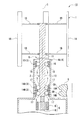
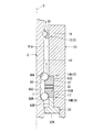
図1、図2に示すように、本発明の第1実施形態に係る垂直軸型風力発電装置(垂直軸型流体発電装置)10は、風(作動流体)Wを受けて回転する回転機構と、回転機構により得られた機械エネルギーを電気エネルギーに変換する発電機構と、を有している。前記回転機構は、回転軸(軸体)2と、風車1の構成要素であり回転軸2の中心軸C回りに間隔をあけて配列されるとともに、該回転軸2に接続される複数のブレード1Aと、軸受3を介して回転軸2を中心軸C回りに回転可能に支持するケーシング(支持体)4と、を備えている。また、前記発電機構は、回転軸2が周方向(中心軸C回り)に回転することで得られる機械エネルギーを電気エネルギーに変換して電力を発電させる発電機5を備えている。これら回転機構及び発電機構は、地面Fに立設されて鉛直方向に延びるタワー(支柱)6の上部に配設されている。
(First embodiment)
As shown in FIGS. 1 and 2, a vertical axis wind power generator (vertical axis fluid power generator) 10 according to a first embodiment of the present invention includes a rotating mechanism that receives wind (working fluid) W and rotates. And a power generation mechanism that converts mechanical energy obtained by the rotation mechanism into electrical energy. The rotating mechanism is a rotating shaft (shaft body) 2 and a plurality of blades connected to the rotating shaft 2 while being arranged around the central axis C of the rotating shaft 2 as a component of the windmill 1. 1A and a casing (supporting body) 4 that supports the rotary shaft 2 so as to be rotatable around the central axis C via a bearing 3. The power generation mechanism includes a generator 5 that generates electric power by converting mechanical energy obtained by rotating the rotating shaft 2 in the circumferential direction (around the central axis C) into electric energy. The rotation mechanism and the power generation mechanism are disposed on an upper portion of a tower (post) 6 that stands on the ground F and extends in the vertical direction.

風Wを受ける風車1は、矩形板状又は帯板状をなし地面Fと鉛直方向に延びるブレード1Aを複数有しており、これらブレード1Aは、中心軸C回りに周方向均等に間隔をあけて配設されている。そのため、風向きに対して依存性がない設定、すなわち、どの方向からの風Wに対しても風車1を回転軸2の中心軸C回りに回転可能な形状に設定されている。   The windmill 1 that receives the wind W has a rectangular plate shape or a band plate shape, and includes a plurality of blades 1A extending in the vertical direction with the ground F. These blades 1A are spaced evenly around the central axis C in the circumferential direction. Arranged. For this reason, the setting has no dependency on the wind direction, that is, the wind turbine 1 is set to have a shape capable of rotating around the central axis C of the rotation shaft 2 with respect to the wind W from any direction.

詳しくは、各ブレード1Aは、風Wを受けると揚力を発生する形状とされているので、この揚力によって風車1が回転軸2の中心軸C回りに回転する。   Specifically, each blade 1 </ b> A is shaped to generate lift when receiving wind W, so that the wind turbine 1 rotates around the central axis C of the rotation shaft 2 by this lift.

また、中心軸Cが地面Fに対して垂直となるように、回転軸2が鉛直方向に延びて配設されている。また、図2において、回転軸2は、鋼材等からなるとともに例えば、ボルト止めや溶接等により風車1(ブレード1A)に一体とされた第1回転部材11と、焼入れ可能な高炭素鋼等からなり軸受3に軸支された第2回転部材12と、を備えている。第1回転部材11の発電機構(発電機5)側の下端部と第2回転部材12の上端部とは、図中に符号Sで示す連結部においてボルト・ナット(ねじ作用による嵌め合い)等により中心軸C方向に連結されている。
尚、前述の説明では第1回転部材11と第2回転部材12とが別体であるとしたが、これらが一体とされていてもよい。
Further, the rotary shaft 2 is arranged extending in the vertical direction so that the central axis C is perpendicular to the ground F. In FIG. 2, the rotating shaft 2 is made of a steel material and the like, for example, a first rotating member 11 integrated with the windmill 1 (blade 1 </ b> A) by bolting, welding, or the like, and a quenchable high carbon steel or the like. And a second rotating member 12 supported by the bearing 3. The lower end portion of the first rotating member 11 on the power generation mechanism (generator 5) side and the upper end portion of the second rotating member 12 are bolts and nuts (fitting by screw action) or the like at the connecting portion indicated by S in the drawing. Are connected in the direction of the central axis C.
In the above description, the first rotating member 11 and the second rotating member 12 are separate, but they may be integrated.

第1回転部材11の外周面には、矩形板状又は帯板状をなすアーム1Bの一端が接続され径方向外方へ向けて複数突設されているとともに、これらアーム1Bは周方向均等に間隔をあけて配設されている。また、アーム1Bの他端は、ブレード1Aに連結されている。図示の例では、1つのブレード1Aに対応して、該ブレード1Aを支持するアーム1Bが中心軸C方向に離間して一対設けられている。
本実施形態の風車1は、風Wを受ける複数のブレード1Aと、これらブレード1Aを支持する複数のアーム1Bとを備えた、所謂ジャイロミル型風車である。
One end of an arm 1B having a rectangular plate shape or a band plate shape is connected to the outer peripheral surface of the first rotating member 11, and a plurality of radially outward projections are provided. These arms 1B are evenly arranged in the circumferential direction. They are arranged at intervals. The other end of the arm 1B is connected to the blade 1A. In the example shown in the figure, a pair of arms 1B supporting the blade 1A are provided so as to be separated from each other in the direction of the central axis C corresponding to one blade 1A.
The windmill 1 according to this embodiment is a so-called gyromill type windmill including a plurality of blades 1A that receive the wind W and a plurality of arms 1B that support the blades 1A.

また、第2回転部材12は、その上端部近傍と下端部近傍とに軸受3がそれぞれ設けられることにより、ケーシング4に対して回転可能とされている。軸受3は、回転軸2の中心軸C方向に互いに離間するラジアル軸受13と、複列のアンギュラ軸受14A、14Bと、を備えている。図示の例では、第2回転部材12の上端部にラジアル軸受13が設けられ、第2回転部材12の下端部近傍に複列のアンギュラ軸受14A、14Bが設けられている。詳しくは、ラジアル軸受13は、回転軸2における中心軸C方向に沿う風車1側(一方側)に配設され、複列のアンギュラ軸受14A、14Bは、回転軸2の中心軸C方向に沿う発電機5側(他方側)の端部に配設されている。
尚、ラジアル軸受13とアンギュラ軸受14A、14Bとの上下位置は、前述とは反対に設定されていてもよい。すなわち、ラジアル軸受13が回転軸2の中心軸C方向に沿う発電機5側に配設され、アンギュラ軸受14A、14Bが回転軸2の中心軸C方向に沿う風車1側に配設されていてもよい。
The second rotating member 12 is rotatable with respect to the casing 4 by providing the bearings 3 in the vicinity of the upper end portion and in the vicinity of the lower end portion thereof. The bearing 3 includes radial bearings 13 that are separated from each other in the direction of the central axis C of the rotary shaft 2 and double-row angular bearings 14A and 14B. In the illustrated example, a radial bearing 13 is provided at the upper end of the second rotating member 12, and double-row angular bearings 14 </ b> A and 14 </ b> B are provided near the lower end of the second rotating member 12. Specifically, the radial bearing 13 is disposed on the wind turbine 1 side (one side) along the central axis C direction of the rotary shaft 2, and the double-row angular bearings 14 </ b> A and 14 </ b> B are along the central axis C direction of the rotary shaft 2. It is arrange | positioned at the edge part of the generator 5 side (other side).
Note that the vertical positions of the radial bearing 13 and the angular bearings 14A and 14B may be set opposite to the above. That is, the radial bearing 13 is disposed on the generator 5 side along the central axis C direction of the rotating shaft 2, and the angular bearings 14 </ b> A and 14 </ b> B are disposed on the windmill 1 side along the central axis C direction of the rotating shaft 2. Also good.

また、第2回転部材12においてラジアル軸受13が設けられる部分と、複列のアンギュラ軸受14A、14Bが設けられる部分とには、複数のボール(転動体)7が転走する転走面がそれぞれ設けられている。   In addition, the rolling surface on which the plurality of balls (rolling elements) 7 rolls is formed in the portion where the radial bearing 13 is provided in the second rotating member 12 and the portion where the double row angular bearings 14A and 14B are provided. Is provided.

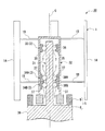
ラジアル軸受13は、第2回転部材12の転走面を転走する複数のボール7と、これらボール7の径方向に当接して該ボール7を転走させる環状の外輪15と、を有している。また、第2回転部材12のラジアル軸受13に対応する転走面には、ボール7を転走させる第1溝部16が形成されている。第1溝部16は、第2回転部材12の外周面において周方向に沿って延びる環状をなしており、図2の側断面視において中心軸C側に向かって窪む凹曲線状とされている。   The radial bearing 13 includes a plurality of balls 7 that roll on the rolling surface of the second rotating member 12, and an annular outer ring 15 that abuts in the radial direction of the balls 7 and rolls the balls 7. ing. A first groove 16 for rolling the ball 7 is formed on the rolling surface of the second rotating member 12 corresponding to the radial bearing 13. The first groove portion 16 has an annular shape extending along the circumferential direction on the outer peripheral surface of the second rotating member 12, and has a concave curve shape that is recessed toward the central axis C side in a side sectional view of FIG. .

アンギュラ軸受14A(14B)は、第2回転部材12の転走面を転走する複数のボール7と、これらボール7の径方向に当接して該ボール7を転走させる環状の外輪17と、を有している。図示の例では、複列のアンギュラ軸受14A、14B同士は、互いに背面合わせに配設されている。このように背面合わせに配設されることにより、アンギュラ軸受14A、14B同士の作用点間距離を大きく設定できることから、モーメント剛性が高められる。尚、これらアンギュラ軸受14A、14B同士は、背面合わせ以外の正面合わせや並列合わせとされていてもよい。また、図示の例においては、アンギュラ軸受14A、14B同士は、互いの外輪17、17を直接当接させており、この当接によってボール7に予圧を付与しているが、この代わりに、アンギュラ軸受14A、14Bの間にスペーサや弾性体を挟んで前記予圧を付与することとしても構わない。   The angular bearing 14A (14B) includes a plurality of balls 7 that roll on the rolling surface of the second rotating member 12, and an annular outer ring 17 that abuts in the radial direction of the balls 7 to roll the balls 7. have. In the illustrated example, the double-row angular bearings 14A and 14B are arranged back to back. Since the distances between the operating points of the angular bearings 14A and 14B can be set large by arranging them so as to be back-to-back in this way, the moment rigidity is increased. In addition, these angular bearings 14A and 14B may be set as front alignment or parallel alignment other than back alignment. In the illustrated example, the angular bearings 14A and 14B directly contact each other's outer rings 17 and 17 to apply a preload to the ball 7 by this contact. The preload may be applied by sandwiching a spacer or an elastic body between the bearings 14A and 14B.

第2回転部材12の複列のアンギュラ軸受14A、14Bに対応する転走面には、各列のボール7を転走させる複列の第2溝部18A、18Bが形成されている。第2溝部18A、18Bは、第2回転部材12の外周面において周方向に沿って延びる環状をなしており、図2の側断面視において中心軸C側に向かって窪む凹曲線状とされている。   On the rolling surfaces corresponding to the double row angular bearings 14A and 14B of the second rotating member 12, double row second groove portions 18A and 18B for rolling the balls 7 in each row are formed. The second groove portions 18A and 18B have an annular shape extending along the circumferential direction on the outer peripheral surface of the second rotating member 12, and have a concave curve shape that is recessed toward the central axis C side in a side sectional view of FIG. ing.

図2中の符号Gは、これら第2溝部18A、18Bを研削加工するための円板状の砥石の一部断面を示している。砥石Gの外周面には、径方向外方へ突出するとともに周方向に沿って延びる環状をなし、互いに軸方向に離間された凸部GA、GBが形成されている。これら凸部GA、GBは、外周面からの突出高さや形状が互いに同一に設定されている。このような砥石Gによって、第2溝部18A、18Bは同一工程で同一形状に研削加工される。   The code | symbol G in FIG. 2 has shown the partial cross section of the disk-shaped grindstone for grinding these 2nd groove parts 18A and 18B. On the outer peripheral surface of the grindstone G, there are formed convex portions GA and GB that protrude outward in the radial direction and have an annular shape extending along the circumferential direction and are spaced apart from each other in the axial direction. The protrusions GA and GB are set to have the same protruding height and shape from the outer peripheral surface. With such a grindstone G, the second groove portions 18A and 18B are ground into the same shape in the same process.

また、図1において、ケーシング4は、例えば、風車1側(一方側)の上側部分4Aが該風車1とは反対のタワー6側(他方側)の下側部分4Bよりも縮径された多段筒状をなしており、下側部分4Bの下端部は、タワー6の上端部に連結されている。図2において、ケーシング4の上側部分4Aの内周面における上端部には、ラジアル軸受13のボール7を挟んで第1溝部16に対向して、該ラジアル軸受13の外輪15が固設されている。また、上側部分4Aの内周面における下端部近傍には、アンギュラ軸受14A、14Bのボール7、7を挟んで第2溝部18A、18Bに対向して、該アンギュラ軸受14A、14Bの外輪17、17が固設されている。また、ケーシング4の下側部分4B内には、発電機5や制御部(不図示)等が収容されている。   In FIG. 1, the casing 4 has a multistage structure in which, for example, the upper portion 4 </ b> A on the windmill 1 side (one side) is reduced in diameter than the lower portion 4 </ b> B on the tower 6 side (the other side) opposite to the windmill 1. It has a cylindrical shape, and the lower end portion of the lower portion 4 </ b> B is connected to the upper end portion of the tower 6. In FIG. 2, an outer ring 15 of the radial bearing 13 is fixed to an upper end portion of the inner peripheral surface of the upper portion 4 </ b> A of the casing 4 so as to face the first groove portion 16 with the ball 7 of the radial bearing 13 interposed therebetween. Yes. Further, in the vicinity of the lower end portion on the inner peripheral surface of the upper portion 4A, the outer rings 17 of the angular bearings 14A and 14B are opposed to the second groove portions 18A and 18B across the balls 7 and 7 of the angular bearings 14A and 14B. 17 is fixed. Further, a generator 5, a control unit (not shown), and the like are accommodated in the lower portion 4 </ b> B of the casing 4.

発電機5は、回転軸2の回転によって得られる回転力(機械エネルギー)を電気エネルギーに変換して電力を発電するものである。発電機5は、回転軸2の下端部の径方向に連結されて該回転軸2とともに回転するマグネットロータ8と、マグネットロータ8の外周側を取り囲むようにケーシング4の下側部分4Bに配設されたコイルステータ9と、を備えている。   The generator 5 generates electric power by converting the rotational force (mechanical energy) obtained by the rotation of the rotary shaft 2 into electric energy. The generator 5 is connected to the lower end portion 4B of the casing 4 so as to surround the outer periphery of the magnet rotor 8 coupled to the lower end portion of the rotating shaft 2 in the radial direction and rotating together with the rotating shaft 2. The coil stator 9 is provided.

そして、風車1が風Wを受けて回転軸2の中心軸C回りに回転すると、この回転が回転軸2を介してマグネットロータ8に伝わって、マグネットロータ8が風車1及び回転軸2と同軸上で回転する。マグネットロータ8がコイルステータ9に対して中心軸C回りに回転することにより、マグネットロータ8とコイルステータ9との間で電磁誘導が発生して、電力が発電される。   When the windmill 1 receives the wind W and rotates around the central axis C of the rotation shaft 2, this rotation is transmitted to the magnet rotor 8 via the rotation shaft 2, and the magnet rotor 8 is coaxial with the windmill 1 and the rotation shaft 2. Rotate up. When the magnet rotor 8 rotates about the central axis C with respect to the coil stator 9, electromagnetic induction is generated between the magnet rotor 8 and the coil stator 9, and electric power is generated.

以上説明したように、本実施形態に係る垂直軸型風力発電装置10によれば、軸受3が設けられることにより、回転軸2がケーシング4に対して該回転軸2の中心軸C回りに回転可能とされており、前記軸受3が、ラジアル軸受13と、複列のアンギュラ軸受14A、14Bとを含んでいる。これらラジアル軸受13及びアンギュラ軸受14A、14Bが設けられることにより、下記のような作用効果を奏する。   As described above, according to the vertical axis wind power generator 10 according to the present embodiment, the rotation shaft 2 rotates about the central axis C of the rotation shaft 2 with respect to the casing 4 by providing the bearing 3. The bearing 3 includes a radial bearing 13 and double row angular bearings 14A and 14B. By providing the radial bearing 13 and the angular bearings 14A and 14B, the following effects can be obtained.

すなわち、軸受3としてラジアル軸受13が設けられることにより、風Wを受けることによって風車1及び回転軸2に対して中心軸Cに交差する水平方向(ラジアル方向)に外力が作用した際、ラジアル軸受13は荷重を確実に受けとめつつ回転軸2を円滑に回転させることができる。また、軸受3としてアンギュラ軸受14A、14Bが設けられることにより、アンギュラ軸受14A、14Bは前述のラジアル方向の荷重を受けとめつつ、風車1及び回転軸2の自重等により生じる中心軸C方向(スラスト方向)への荷重を確実に受けとめて、回転軸2を円滑に回転させることができる。   That is, when the radial bearing 13 is provided as the bearing 3, when the external force is applied to the wind turbine 1 and the rotary shaft 2 in the horizontal direction (radial direction) intersecting the central axis C by receiving the wind W, the radial bearing 13 is provided. 13 can smoothly rotate the rotary shaft 2 while receiving the load with certainty. Further, by providing the angular bearings 14A and 14B as the bearing 3, the angular bearings 14A and 14B receive the above-described radial load, and the central axis C direction (thrust direction) generated by the own weight of the windmill 1 and the rotary shaft 2 or the like. ) Can be reliably received, and the rotating shaft 2 can be smoothly rotated.

さらに、アンギュラ軸受14A、14Bが複列とされていることから、これらアンギュラ軸受14A、14Bを本実施形態で説明した背面合わせ(DB構造)に組み合わせることにより、アンギュラ軸受14A、14Bはスラスト方向の両側(上下)への荷重を確実に受けとめることができる。   Further, since the angular bearings 14A and 14B are double-rowed, the angular bearings 14A and 14B are arranged in the thrust direction by combining the angular bearings 14A and 14B with the back-to-back alignment (DB structure) described in the present embodiment. The load on both sides (up and down) can be reliably received.

このように、本実施形態の軸受3(ラジアル軸受13及びアンギュラ軸受14A、14Bの組合せ)は、ラジアル方向及びスラスト方向への荷重を確実に受けとめるので、風Wを受けることや風車1及び回転軸2の自重等による振動が確実に抑制(吸収)されるとともに、回転軸2の回転がスムースとなる。これにより、たとえ風車1に当たる風Wの風量(風速)が微かなものであっても、風車1及び回転軸2が回転しやすくされているので、垂直軸型風力発電装置10の発電効率が高められるのである。   Thus, since the bearing 3 (combination of the radial bearing 13 and the angular bearings 14A and 14B) of the present embodiment reliably receives the load in the radial direction and the thrust direction, it receives the wind W, the wind turbine 1 and the rotating shaft. The vibration due to the weight of 2 is reliably suppressed (absorbed), and the rotation of the rotating shaft 2 is smooth. Thereby, even if the air volume (wind speed) of the wind W that hits the windmill 1 is small, the windmill 1 and the rotary shaft 2 are easily rotated, so that the power generation efficiency of the vertical axis wind power generator 10 is increased. It is done.

また、ラジアル軸受13とアンギュラ軸受14A、14Bとは、回転軸2の中心軸C方向に互いに離間して配置されているので、回転軸2の回転中心が中心軸Cから振れにくくなり、該回転軸2の回転がより安定して高精度に行われる。   Further, since the radial bearing 13 and the angular bearings 14A and 14B are arranged apart from each other in the direction of the central axis C of the rotary shaft 2, the rotational center of the rotary shaft 2 is less likely to swing from the central axis C, and the rotation The rotation of the shaft 2 is performed more stably and with high accuracy.

また、回転軸2の外周面には、ラジアル軸受13のボール7を転走させる転走面である第1溝部16と、複列のアンギュラ軸受14A、14Bの各ボール7を転走させる転走面である複列の第2溝部18A、18Bと、が形成されているとともに、回転軸2と軸受3とが一体の構成とされているので、下記のような作用効果が得られる。   Further, on the outer peripheral surface of the rotary shaft 2, the first groove portion 16 which is a rolling surface for rolling the balls 7 of the radial bearing 13 and the rolling for rolling the balls 7 of the double row angular bearings 14 </ b> A and 14 </ b> B. Since the double-row second groove portions 18A and 18B, which are surfaces, are formed and the rotary shaft 2 and the bearing 3 are integrated, the following operational effects are obtained.

すなわち、ラジアル軸受13のボール7及びアンギュラ軸受14A、14Bの各ボール7が、回転軸2の外周面(転走面)上を直接転動することから、ラジアル軸受13とアンギュラ軸受14A、14Bとの同軸度が向上するとともに、回転軸2の回転中心が中心軸C上に重なるように精度よく位置することとなる。これにより、回転軸2の回転がスムースとなるので、たとえ風車1に当たる風Wの風量(風速)が微かなものであっても風車1(及び回転軸2)が回転しやすくなり、発電効率が高められる。   That is, since the balls 7 of the radial bearing 13 and the balls 7 of the angular bearings 14A, 14B roll directly on the outer peripheral surface (rolling surface) of the rotating shaft 2, the radial bearing 13 and the angular bearings 14A, 14B The center of rotation of the rotary shaft 2 is accurately positioned so as to overlap the central axis C. Thereby, since rotation of the rotating shaft 2 becomes smooth, even if the air volume (wind speed) of the wind W which hits the windmill 1 is slight, the windmill 1 (and the rotating shaft 2) is easily rotated, and the power generation efficiency is improved. Enhanced.

詳しくは、例えば、回転軸2が中心軸C方向に離間して設けられた従来の一対の軸受を介してケーシング4に支持された構成においては、これら軸受を取り付ける回転軸2部分及びケーシング4部分の加工誤差や組み付け誤差(傾き、隙間)により、前記軸受同士の同軸度を出すことは難しかった。一方、本実施形態の垂直軸型風力発電装置10においては、ボール7を転走させる第1溝部16、第2溝部18A、18Bが回転軸2の外周面(転走面)上に直接形成されていることから、前述の加工誤差や組み付け誤差を大幅に低減でき、ラジアル軸受13とアンギュラ軸受14A、14Bとの同軸度が高精度に設定されるのである。   Specifically, for example, in a configuration in which the rotating shaft 2 is supported by the casing 4 via a pair of conventional bearings provided to be separated in the direction of the central axis C, the rotating shaft 2 portion and the casing 4 portion to which these bearings are attached. It was difficult to obtain the same degree of coaxiality between the bearings due to the machining error and assembly error (tilt, gap). On the other hand, in the vertical axis wind power generator 10 of the present embodiment, the first groove portion 16 and the second groove portions 18A and 18B for rolling the ball 7 are directly formed on the outer peripheral surface (rolling surface) of the rotating shaft 2. Therefore, the processing error and assembly error described above can be greatly reduced, and the coaxiality between the radial bearing 13 and the angular bearings 14A and 14B is set with high accuracy.

また一般に、複列のアンギュラ軸受を用いる場合においては、該アンギュラ軸受の各列同士の配置間隔(中心軸C方向に沿うボール7、7同士のピッチ)を精度よく設定することは難しかった。すなわち、複列のアンギュラ軸受においては、各列の内輪同士・外輪同士を互いに中心軸C方向に接近・離間させる向きに位置調整して、ボール7に対する予圧を調整しているとともに、該ボール7のがたを無くし剛性及び精度を確保するようにしている。しかしながら、この位置調整が難しく、前記配置間隔が所定の寸法に決まらなかった場合にボール7に対する予圧が不足又は不安定となり、回転軸2を回転させるためのトルク(回転トルク)が大きくなってしまうことがあった。このように回転トルクが大きくなることは、垂直軸型風力発電装置の発電効率を低下させることから好ましくない。   In general, when a double-row angular bearing is used, it is difficult to accurately set the arrangement interval (the pitch between the balls 7 and 7 along the central axis C direction) between the rows of the angular bearing. That is, in the double-row angular bearing, the inner ring and the outer ring of each row are adjusted in the direction of approaching and separating from each other in the direction of the central axis C to adjust the preload on the ball 7. Roughness is eliminated to ensure rigidity and accuracy. However, this position adjustment is difficult, and when the arrangement interval is not determined to be a predetermined size, the preload on the ball 7 becomes insufficient or unstable, and the torque (rotational torque) for rotating the rotating shaft 2 increases. There was a thing. Such a large rotational torque is not preferable because it reduces the power generation efficiency of the vertical axis wind power generator.

一方、本実施形態の垂直軸型風力発電装置10では、複列のアンギュラ軸受14A、14B同士の前記配置間隔は、回転軸2に直接形成された複列の第2溝部18A、18Bにより精度よく簡単に決まるので、アンギュラ軸受14A、14Bの各列同士の位置調整が容易である。詳しくは、本実施形態で説明したように、例えば、第2溝部18A、18Bを同一工程で研削加工できる砥石Gを用いることにより、前記配置間隔を高精度かつ容易に設定できる。従って、アンギュラ軸受14A、14Bの各列のボール7に対する予圧の精度が確保されて、前記回転トルクが確実に低減されるとともに回転軸2が回転しやすくなり、発電効率が高められるのである。   On the other hand, in the vertical axis wind power generator 10 of the present embodiment, the arrangement interval between the double row angular bearings 14A, 14B is more accurately determined by the double row second groove portions 18A, 18B formed directly on the rotary shaft 2. Since it is determined easily, it is easy to adjust the positions of the rows of the angular bearings 14A and 14B. Specifically, as described in the present embodiment, for example, by using the grindstone G that can grind the second groove portions 18A and 18B in the same process, the arrangement interval can be set with high accuracy and easily. Therefore, the precision of the preload with respect to the balls 7 in each row of the angular bearings 14A and 14B is ensured, the rotational torque is surely reduced, and the rotating shaft 2 is easily rotated, so that the power generation efficiency is increased.

さらに、回転軸2と軸受3とが一体の構成とされていることにより、軸受3の内輪を削除できることから、装置の径方向の外形をコンパクトに形成でき、かつ、コストダウンとなる。   Further, since the rotary shaft 2 and the bearing 3 are integrated, the inner ring of the bearing 3 can be eliminated, so that the outer shape in the radial direction of the apparatus can be made compact and the cost is reduced.

また、この垂直軸型風力発電装置10では、回転軸2が、中心軸C方向に互いに連結された第1、第2回転部材11、12を備えている。すなわち、この回転軸2においては、第1、第2回転部材11、12をそれぞれ別体として製造した後、これらを連結できることから、風車1と一体とされることが好ましい第1回転部材11を該風車1に溶接可能な鋼材等で形成し、軸受3のボール7が直接転走する(すなわち高硬度が望まれる)第2回転部材12を焼入れ可能な高炭素鋼等で形成できる。これにより、第1回転部材11と風車1とを強固に一体化でき、かつ、第2回転部材12の第1溝部16及び第2溝部18A、18Bがボール7を長期に亘り安定して高精度に転走させる。   Further, in the vertical axis wind power generator 10, the rotating shaft 2 includes first and second rotating members 11 and 12 connected to each other in the central axis C direction. That is, in the rotating shaft 2, since the first and second rotating members 11 and 12 are manufactured as separate bodies and can be connected to each other, the first rotating member 11 that is preferably integrated with the windmill 1 is provided. The second rotating member 12 formed of a steel material that can be welded to the windmill 1 and the ball 7 of the bearing 3 directly rolls (that is, high hardness is desired) can be formed of quenchable high carbon steel or the like. Thereby, the 1st rotation member 11 and the windmill 1 can be firmly integrated, and the 1st groove part 16 and 2nd groove part 18A, 18B of the 2nd rotation member 12 are stable and highly accurate over a long period of time. Make a roll.

また、アンギュラ軸受14A、14Bが回転軸2において中心軸C方向の発電機5側(他方側)に配設されていることから、該アンギュラ軸受14A、14Bを回転軸2の端部(下端部)に配置できる。これにより、下記の作用効果が得られる。   Further, since the angular bearings 14A and 14B are disposed on the generator 5 side (the other side) in the direction of the central axis C in the rotating shaft 2, the angular bearings 14A and 14B are connected to the end portion (lower end portion) of the rotating shaft 2. ). Thereby, the following effects are obtained.

すなわち、一般に、回転軸2の中心軸C方向に対して、複列アンギュラ軸受はラジアル軸受に比べて大きな荷重を受けることができるので、装置のコンパクト化や軽量化等を目的として、図3の変形例に示すように、アンギュラ軸受14A、14Bが配置される回転軸2部分(下端部)の軸径を他の部分の軸径よりも小さく形成する場合が考えられるが、このような場合における回転軸2の加工性が十分に確保される。また、例えば、アンギュラ軸受14A、14Bを回転軸2(第2回転部材12)の上端部や中央部に配設して該アンギュラ軸受14A、14Bに対応する部位を他の部分よりも縮径して形成した場合においては、該縮径した部分が回転軸2を部分的に括れさせることから、該回転軸2の剛性が十分に確保できないことがある。一方、本実施形態の変形例で説明した図3の構成(回転軸2の下端部が縮径されている)によれば、回転軸2を部分的に括れさせないので、剛性が十分に確保される。   That is, in general, the double-row angular bearing can receive a larger load than the radial bearing in the direction of the central axis C of the rotary shaft 2, so that the apparatus shown in FIG. As shown in the modification, it is conceivable that the shaft diameter of the rotary shaft 2 portion (lower end portion) where the angular bearings 14A and 14B are arranged is smaller than the shaft diameter of the other portions. The workability of the rotating shaft 2 is sufficiently ensured. Further, for example, the angular bearings 14A and 14B are disposed at the upper end portion and the central portion of the rotating shaft 2 (second rotating member 12) so that the portions corresponding to the angular bearings 14A and 14B have a smaller diameter than the other portions. In this case, the reduced diameter part partially constricts the rotary shaft 2, so that the rigidity of the rotary shaft 2 may not be sufficiently secured. On the other hand, according to the configuration of FIG. 3 described in the modification of the present embodiment (the lower end portion of the rotating shaft 2 is reduced in diameter), the rotating shaft 2 is not partially constricted, so that sufficient rigidity is ensured. The

また、本実施形態で説明した垂直軸型風力発電装置10は、回転軸2がその中心軸Cを地面Fに垂直な鉛直方向に延ばすように配設されており、回転軸2及び風車1の自重等により、アンギュラ軸受14A、14Bには中心軸C方向に向けて常に負荷がかかっている。また、ラジアル軸受13には中心軸Cの周方向(径方向)に負荷がかかっている。このような垂直軸型風力発電装置10に対して、前述した本実施形態の軸受3の構成を用いることにより、長期に亘り安定して効率よく電力を発電できることから、より有効である。   Further, in the vertical axis wind power generator 10 described in the present embodiment, the rotary shaft 2 is disposed so that the central axis C extends in a vertical direction perpendicular to the ground F, and the rotary shaft 2 and the windmill 1 Due to its own weight, the angular bearings 14A and 14B are always loaded in the direction of the central axis C. Further, the radial bearing 13 is loaded in the circumferential direction (radial direction) of the central axis C. By using the configuration of the bearing 3 of the present embodiment described above for such a vertical axis wind power generator 10, power can be generated stably and efficiently over a long period, which is more effective.

(第2実施形態)
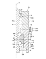
次に、本発明の第2実施形態に係る垂直軸型風力発電装置(垂直軸型流体発電装置)20について、図4を参照して説明する。尚、前述の実施形態と同一部材には同一の符号を付し、その説明を省略する。
(Second Embodiment)
Next, a vertical axis wind power generator (vertical axis hydroelectric generator) 20 according to a second embodiment of the present invention will be described with reference to FIG. In addition, the same code | symbol is attached | subjected to the same member as above-mentioned embodiment, and the description is abbreviate | omitted.

本実施形態の垂直軸型風力発電装置20においては、第1溝部26、第2溝部28A、28Bが、回転軸2に形成される代わりにケーシング4に形成されている点等で、前述の第1実施形態とは異なっている。   In the vertical axis wind power generator 20 of the present embodiment, the first groove portion 26 and the second groove portions 28A and 28B are formed in the casing 4 instead of being formed in the rotating shaft 2, and the like. Different from one embodiment.

この垂直軸型風力発電装置20では、軸受3として、ケーシング4の上側部分4Aの内周面における上端部に配設されたラジアル軸受23と、前記内周面の下端部近傍に配設された複列のアンギュラ軸受24A、24Bと、を備えている。また、ケーシング4の上側部分4Aにおいてラジアル軸受23が設けられる部分と、複列のアンギュラ軸受24A、24Bが設けられる部分とには、複数のボール(転動体)7が転走する転走面がそれぞれ設けられている。   In this vertical shaft type wind power generator 20, as the bearing 3, a radial bearing 23 disposed at the upper end portion of the inner peripheral surface of the upper portion 4A of the casing 4 and the vicinity of the lower end portion of the inner peripheral surface are disposed. Double row angular bearings 24A, 24B. In addition, a rolling surface on which a plurality of balls (rolling elements) 7 rolls is formed in a portion where the radial bearing 23 is provided in the upper portion 4A of the casing 4 and a portion where the double row angular bearings 24A and 24B are provided. Each is provided.

ラジアル軸受23は、ケーシング4の転走面を転走する複数のボール7と、これらボール7の径方向に当接して該ボール7を転走させる環状の内輪25と、を有している。また、ケーシング4のラジアル軸受23に対応する転走面には、ボール7を転走させる第1溝部26が形成されている。第1溝部26は、ケーシング4の内周面において周方向に沿って延びる環状をなしており、図4の側断面視において中心軸Cとは反対側に向かって窪む凹曲線状とされている。   The radial bearing 23 has a plurality of balls 7 that roll on the rolling surface of the casing 4 and an annular inner ring 25 that abuts in the radial direction of the balls 7 and rolls the balls 7. A first groove portion 26 for rolling the ball 7 is formed on the rolling surface of the casing 4 corresponding to the radial bearing 23. The first groove portion 26 has an annular shape extending along the circumferential direction on the inner peripheral surface of the casing 4, and has a concave curve shape that is recessed toward the opposite side to the central axis C in a side sectional view of FIG. 4. Yes.

アンギュラ軸受24A(24B)は、ケーシング4の転走面を転走する複数のボール7と、これらボール7の径方向に当接して該ボール7を転走させる環状の内輪27と、を有している。図示の例においては、アンギュラ軸受24A、24B同士は背面合わせ(DB構造)に組み合わされており、互いの内輪27、27を直接当接させることによってボール7に予圧を付与している。
尚、これらアンギュラ軸受24A、24B同士は、背面合わせ以外の正面合わせや並列合わせとされていてもよい。
The angular bearing 24 </ b> A (24 </ b> B) has a plurality of balls 7 that roll on the rolling surface of the casing 4, and an annular inner ring 27 that contacts the balls 7 in the radial direction and rolls the balls 7. ing. In the illustrated example, the angular bearings 24A, 24B are combined in back-to-back alignment (DB structure), and a preload is applied to the ball 7 by bringing the inner rings 27, 27 into direct contact with each other.
In addition, these angular bearings 24A and 24B may be set as front alignment or parallel alignment other than back alignment.

ケーシング4の複列のアンギュラ軸受24A、24Bに対応する転走面には、各列のボール7を転走させる複列の第2溝部28A、28Bが形成されている。第2溝部28A、28Bは、ケーシング4の内周面において周方向に沿って延びる環状をなしており、図4の側断面視において中心軸Cとは反対側に向かって窪む凹曲線状とされている。   On the rolling surfaces corresponding to the double row angular bearings 24A, 24B of the casing 4, double row second groove portions 28A, 28B for rolling the balls 7 in each row are formed. The second groove portions 28A and 28B have an annular shape extending in the circumferential direction on the inner peripheral surface of the casing 4, and have a concave curve shape that is recessed toward the side opposite to the central axis C in the side sectional view of FIG. Has been.

また、ラジアル軸受23は、第2回転部材12の上端部に配置されているとともに、その内輪25が前記上端部の外周面に固設されている。詳しくは、ラジアル軸受23の内輪25は、該ラジアル軸受23のボール7を挟んで第1溝部26に対向して配置されている。また、アンギュラ軸受24A、24Bは、第2回転部材12の下端部近傍に配置されているとともに、その内輪27、27が前記下端部近傍の外周面に固設されている。詳しくは、アンギュラ軸受24A、24Bの内輪27、27は、該アンギュラ軸受24A、24Bのボール7、7を挟んで第2溝部28A、28Bに対向して配置されている。
尚、ラジアル軸受23とアンギュラ軸受24A、24Bとの上下位置は、前述とは反対に設定されていてもよい。すなわち、ラジアル軸受23が回転軸2の中心軸C方向に沿う発電機5側に配設され、アンギュラ軸受24A、24Bが回転軸2の中心軸C方向に沿う風車1側に配設されていてもよい。
The radial bearing 23 is disposed at the upper end portion of the second rotating member 12, and the inner ring 25 is fixed to the outer peripheral surface of the upper end portion. Specifically, the inner ring 25 of the radial bearing 23 is disposed to face the first groove portion 26 with the ball 7 of the radial bearing 23 interposed therebetween. Further, the angular bearings 24A and 24B are disposed in the vicinity of the lower end portion of the second rotating member 12, and the inner rings 27 and 27 are fixed to the outer peripheral surface in the vicinity of the lower end portion. Specifically, the inner rings 27, 27 of the angular bearings 24A, 24B are disposed to face the second groove portions 28A, 28B with the balls 7, 7 of the angular bearings 24A, 24B interposed therebetween.
Note that the vertical positions of the radial bearing 23 and the angular bearings 24A and 24B may be set opposite to the above. That is, the radial bearing 23 is disposed on the generator 5 side along the central axis C direction of the rotating shaft 2, and the angular bearings 24 </ b> A and 24 </ b> B are disposed on the windmill 1 side along the central axis C direction of the rotating shaft 2. Also good.

本実施形態の垂直軸型風力発電装置20においても、前述した垂直軸型風力発電装置10と同様の作用効果が得られる。
すなわち、軸受3(ラジアル軸受23及び複列のアンギュラ軸受24A、24Bの組合せ)がラジアル方向及びスラスト方向への荷重を確実に受けとめるので、風Wを受けることや風車1及び回転軸2の自重等による振動が確実に抑制(吸収)されるとともに、回転軸2の回転がスムースとなる。これにより、たとえ風車1に当たる風Wの風量(風速)が微かなものであっても、風車1及び回転軸2が回転しやすくされているので、垂直軸型風力発電装置20の発電効率が高められる。
Also in the vertical axis wind power generator 20 of the present embodiment, the same operational effects as those of the vertical axis wind power generator 10 described above can be obtained.
That is, since the bearing 3 (the combination of the radial bearing 23 and the double row angular bearings 24A and 24B) reliably receives the load in the radial direction and the thrust direction, the bearing 3 receives the wind W, the weight of the windmill 1 and the rotating shaft 2, etc. Is reliably suppressed (absorbed) and the rotation of the rotary shaft 2 is smooth. Thereby, even if the air volume (wind speed) of the wind W that hits the windmill 1 is small, the windmill 1 and the rotary shaft 2 are easily rotated, so that the power generation efficiency of the vertical axis wind power generator 20 is increased. It is done.

また、ケーシング4の内周面には、ラジアル軸受23のボール7を転走させる転走面である第1溝部26と、複列のアンギュラ軸受24A、24Bの各ボール7を転走させる転走面である複列の第2溝部28A、28Bと、が形成されているとともに、ケーシング4と軸受3とが一体の構成とされているので、下記のような作用効果が得られる。   Further, on the inner peripheral surface of the casing 4, a first groove portion 26 that is a rolling surface for rolling the ball 7 of the radial bearing 23 and a rolling for rolling each ball 7 of the double row angular bearings 24 </ b> A and 24 </ b> B. Since the double-row second groove portions 28A and 28B, which are surfaces, are formed and the casing 4 and the bearing 3 are integrated, the following operational effects can be obtained.

すなわち、ラジアル軸受23のボール7及びアンギュラ軸受24A、24Bの各ボール7が、ケーシング4の内周面(転走面)上を直接転動することから、ラジアル軸受23とアンギュラ軸受24A、24Bとの同軸度が向上するとともに、回転軸2の回転中心が中心軸C上に重なるように精度よく位置することとなる。これにより、回転軸2の回転がスムースとなるので、たとえ風車1に当たる風Wの風量(風速)が微かなものであっても風車1(及び回転軸2)が回転しやすくなり、発電効率が高められる。   That is, since the balls 7 of the radial bearing 23 and the balls 7 of the angular bearings 24A, 24B roll directly on the inner peripheral surface (rolling surface) of the casing 4, the radial bearing 23 and the angular bearings 24A, 24B The center of rotation of the rotary shaft 2 is accurately positioned so as to overlap the central axis C. Thereby, since rotation of the rotating shaft 2 becomes smooth, even if the air volume (wind speed) of the wind W which hits the windmill 1 is slight, the windmill 1 (and the rotating shaft 2) is easily rotated, and the power generation efficiency is improved. Enhanced.

尚、本実施形態の垂直軸型風力発電装置20においては、前述の実施形態のように回転軸2の外周面上をボール7が転走しないことから、第2回転部材12として高炭素硬等を用いる代わりに、鋼材等を用いてもよい。この場合、回転軸2全体を鋼材等により一体に形成してもよい。
また、ラジアル軸受23の内輪25及びアンギュラ軸受24A、24Bの内輪27を用いずに、回転軸2の外周面上に第1実施形態で説明した転走面である第1溝部16及び第2溝部18A、18Bを形成して、ラジアル軸受23及びアンギュラ軸受24A、24Bの内輪・外輪を削除しても構わない。この場合、装置の外形(直径)がよりコンパクトとなり、さらなるコストダウンが可能である。詳しくは、本発明の第1溝部、第2溝部は、回転軸2及びケーシング4の少なくとも一方(すなわち回転軸2又は/及びケーシング4)に形成される。
In the vertical axis wind power generator 20 of the present embodiment, since the ball 7 does not roll on the outer peripheral surface of the rotating shaft 2 as in the above-described embodiment, the second rotating member 12 is made of high carbon hard or the like. Instead of using steel, a steel material or the like may be used. In this case, the entire rotating shaft 2 may be integrally formed of a steel material or the like.
Further, without using the inner ring 25 of the radial bearing 23 and the inner ring 27 of the angular bearings 24A and 24B, the first groove portion 16 and the second groove portion which are the rolling surfaces described in the first embodiment on the outer peripheral surface of the rotating shaft 2. 18A and 18B may be formed, and the inner and outer rings of the radial bearing 23 and the angular bearings 24A and 24B may be deleted. In this case, the outer shape (diameter) of the device becomes more compact, and further cost reduction is possible. Specifically, the first groove portion and the second groove portion of the present invention are formed in at least one of the rotating shaft 2 and the casing 4 (that is, the rotating shaft 2 and / or the casing 4).

(第3実施形態)
次に、本発明の第3実施形態に係る垂直軸型風力発電装置(垂直軸型流体発電装置)30について、図5〜図9を参照して説明する。尚、前述の実施形態と同一部材には同一の符号を付し、その説明を省略する。
(Third embodiment)
Next, a vertical axis wind power generator (vertical axis hydroelectric generator) 30 according to a third embodiment of the present invention will be described with reference to FIGS. In addition, the same code | symbol is attached | subjected to the same member as above-mentioned embodiment, and the description is abbreviate | omitted.

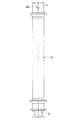
図5に示すように、本実施形態の垂直軸型風力発電装置30は、回転軸(軸体)32が中空軸状(筒状)をなしており、この回転軸32の内部に同軸に収容された支持軸(支持体)31が、軸受3を介して該回転軸32を中心軸C側(径方向の内側)から回転軸32の中心軸C回りに回転可能に支持している。回転軸32の外周面には、風車1のアーム1Bが突設されている。また、回転軸32の下端部(の径方向)には、マグネットロータ8が配設されている。   As shown in FIG. 5, in the vertical shaft type wind power generator 30 of the present embodiment, the rotating shaft (shaft body) 32 has a hollow shaft shape (tubular shape), and is accommodated coaxially within the rotating shaft 32. The support shaft (support body) 31 supports the rotary shaft 32 via the bearing 3 so as to be rotatable around the central axis C of the rotary shaft 32 from the central axis C side (inside in the radial direction). An arm 1 </ b> B of the windmill 1 projects from the outer peripheral surface of the rotating shaft 32. A magnet rotor 8 is disposed at the lower end (in the radial direction) of the rotating shaft 32.

支持軸31の下端部は、該支持軸31よりも大径の支持台39に支持されており、支持台39の下端部は図示しないタワー6の上端部に連結されている。また、支持台39の上面には、マグネットロータ8を囲繞するようにコイルステータ9が配設されている。そして、マグネットロータ8及びコイルステータ9を備えた発電機5が形成されている。尚、図5の例では、支持軸31は中実の軸状に形成されており、図6〜図9に示す例では、支持軸31は中空の軸状(筒状)に形成されている。   The lower end portion of the support shaft 31 is supported by a support base 39 having a larger diameter than the support shaft 31, and the lower end portion of the support base 39 is connected to the upper end portion of the tower 6 (not shown). A coil stator 9 is disposed on the upper surface of the support base 39 so as to surround the magnet rotor 8. And the generator 5 provided with the magnet rotor 8 and the coil stator 9 is formed. In the example of FIG. 5, the support shaft 31 is formed in a solid shaft shape, and in the examples shown in FIGS. 6 to 9, the support shaft 31 is formed in a hollow shaft shape (tubular shape). .

回転軸32は、その内周面における上端部近傍と下端部近傍とに軸受3がそれぞれ設けられることにより、支持軸31に対して回転可能とされている。軸受3は、回転軸32の中心軸C方向に互いに離間するラジアル軸受33と、複列のアンギュラ軸受34A、34Bと、を備えている。図示の例では、回転軸32の上端部にラジアル軸受33が設けられ、回転軸32の下端部近傍に複列のアンギュラ軸受34A、34Bが設けられている。
尚、ラジアル軸受33とアンギュラ軸受34A、34Bとの上下位置は、前述とは反対に設定されていてもよい。すなわち、回転軸32の上端部にアンギュラ軸受34A、34Bが設けられ、回転軸32の下端部近傍にラジアル軸受33が設けられていてもよい。
The rotation shaft 32 is rotatable with respect to the support shaft 31 by providing the bearings 3 in the vicinity of the upper end portion and in the vicinity of the lower end portion on the inner peripheral surface thereof. The bearing 3 includes radial bearings 33 that are separated from each other in the direction of the central axis C of the rotary shaft 32 and double-row angular bearings 34A and 34B. In the illustrated example, a radial bearing 33 is provided at the upper end of the rotating shaft 32, and double-row angular bearings 34 </ b> A and 34 </ b> B are provided near the lower end of the rotating shaft 32.
Note that the vertical positions of the radial bearing 33 and the angular bearings 34A, 34B may be set opposite to the above. That is, the angular bearings 34 </ b> A and 34 </ b> B may be provided at the upper end portion of the rotating shaft 32, and the radial bearing 33 may be provided near the lower end portion of the rotating shaft 32.

また、支持軸31においてラジアル軸受33が設けられる部分と、背面合わせ(DB構造)の複列のアンギュラ軸受34A、34Bが設けられる部分とには、複数のボール7が転走する転走面がそれぞれ設けられている。   In addition, a rolling surface on which a plurality of balls 7 rolls is formed between a portion where the radial bearing 33 is provided on the support shaft 31 and a portion where the double-row angular bearings 34A and 34B of back-to-back (DB structure) are provided. Each is provided.

ラジアル軸受33は、支持軸31の転走面を転走する複数のボール7と、これらボール7の径方向に当接して該ボール7を転走させる環状の外輪35と、を有している。外輪35は、回転軸32の内周面における上端部に固設されている。また、支持軸31のラジアル軸受33に対応する転走面には、ボール7を転走させる第1溝部36が形成されている。第1溝部36は、支持軸31の外周面において周方向に沿って延びる環状をなしており、図5の側断面視において中心軸C側に向かって窪む凹曲線状とされている。ラジアル軸受33の外輪35は、該ラジアル軸受33のボール7を挟んで第1溝部36に対向して配置されている。製造時において、ラジアル軸受33内にボール7を充填(挿入)する際には、図8において、回転軸32の外周面に開閉可能とされた転動体挿入部32Aからボール7を挿入すればよい。   The radial bearing 33 has a plurality of balls 7 that roll on the rolling surface of the support shaft 31 and an annular outer ring 35 that abuts in the radial direction of the balls 7 and rolls the balls 7. . The outer ring 35 is fixed to the upper end portion of the inner peripheral surface of the rotating shaft 32. A first groove 36 for rolling the ball 7 is formed on the rolling surface of the support shaft 31 corresponding to the radial bearing 33. The first groove portion 36 has an annular shape extending along the circumferential direction on the outer peripheral surface of the support shaft 31, and has a concave curve shape that is recessed toward the central axis C side in a side sectional view of FIG. The outer ring 35 of the radial bearing 33 is disposed to face the first groove portion 36 with the ball 7 of the radial bearing 33 interposed therebetween. When the ball 7 is filled (inserted) into the radial bearing 33 during manufacturing, the ball 7 may be inserted from the rolling element insertion portion 32A that can be opened and closed on the outer peripheral surface of the rotating shaft 32 in FIG. .

アンギュラ軸受34A(34B)は、支持軸31の転走面を転走する複数のボール7と、これらボール7の径方向に当接して該ボール7を転走させる環状の外輪37と、を有している。外輪37は、回転軸32の内周面における下端部近傍に固設されている。図5の例では、複列のアンギュラ軸受34A、34B同士は、背面合わせに互いに当接して配置されている。図6〜図9の例では、背面合わせに組み合わせた複列のアンギュラ軸受34A、34B同士の間にはスペーサ40が配設されており、このスペーサ40によって各列のボール7、7に予圧を付与するようにしている。   The angular bearing 34 </ b> A (34 </ b> B) has a plurality of balls 7 that roll on the rolling surface of the support shaft 31 and an annular outer ring 37 that abuts the balls 7 in the radial direction and rolls the balls 7. doing. The outer ring 37 is fixed near the lower end portion of the inner peripheral surface of the rotating shaft 32. In the example of FIG. 5, the double row angular bearings 34 </ b> A and 34 </ b> B are arranged in contact with each other for back-to-back alignment. In the example of FIGS. 6 to 9, a spacer 40 is disposed between the double row angular bearings 34 </ b> A and 34 </ b> B combined for back-to-back alignment, and this spacer 40 preloads the balls 7 and 7 in each row. It is trying to grant.

また、支持軸31の複列のアンギュラ軸受34A、34Bに対応する転走面には、各列のボール7を転走させる複列の第2溝部38A、38Bが形成されている。第2溝部38A、38Bは、支持軸31の外周面において周方向に沿って延びる環状をなしており、図5の側断面視において中心軸C側に向かって窪む凹曲線状とされている。アンギュラ軸受34A、34Bの外輪37、37は、該アンギュラ軸受34A、34Bのボール7、7を挟んで第2溝部38A、38Bに対向して配置されている。製造時において、アンギュラ軸受34A(34B)内にボール7を充填(挿入)する際には、図9において、外輪37と支持軸31との隙間から下方(上方)へ向けてボール7を挿入すればよい。   In addition, on the rolling surfaces corresponding to the double row angular bearings 34A, 34B of the support shaft 31, double row second groove portions 38A, 38B for rolling the rows 7 of balls 7 are formed. The second groove portions 38A and 38B have an annular shape extending in the circumferential direction on the outer peripheral surface of the support shaft 31, and have a concave curve shape that is recessed toward the central axis C side in a side sectional view of FIG. . The outer rings 37, 37 of the angular bearings 34A, 34B are arranged to face the second groove portions 38A, 38B across the balls 7, 7 of the angular bearings 34A, 34B. During filling, when the ball 7 is filled (inserted) into the angular bearing 34A (34B), the ball 7 is inserted downward (upward) from the gap between the outer ring 37 and the support shaft 31 in FIG. That's fine.

そして、風車1が風Wを受けて回転軸32の中心軸C回りに回転すると、この回転が回転軸32を介してマグネットロータ8に伝わって、マグネットロータ8が風車1及び回転軸32と同軸上で回転する。マグネットロータ8がコイルステータ9に対して中心軸C回りに回転することにより、マグネットロータ8とコイルステータ9との間で電磁誘導が発生して、電力が発電される。   When the windmill 1 receives the wind W and rotates around the central axis C of the rotation shaft 32, this rotation is transmitted to the magnet rotor 8 through the rotation shaft 32, and the magnet rotor 8 is coaxial with the windmill 1 and the rotation shaft 32. Rotate up. When the magnet rotor 8 rotates about the central axis C with respect to the coil stator 9, electromagnetic induction is generated between the magnet rotor 8 and the coil stator 9, and electric power is generated.

本実施形態の垂直軸型風力発電装置30においても、前述した垂直軸型風力発電装置10、20と同様の作用効果が得られる。
また、本実施形態の垂直軸型風力発電装置30では、軸受3に加わるモーメントが小さくなることから、モーメントによるラジアル荷重が小さくなる。
Also in the vertical axis wind power generator 30 of the present embodiment, the same effects as those of the vertical axis wind power generators 10 and 20 described above can be obtained.
Moreover, in the vertical axis wind power generator 30 of this embodiment, since the moment added to the bearing 3 becomes small, the radial load by a moment becomes small.

尚、本発明は前述した実施形態に限定されるものではなく、本発明の趣旨を逸脱しない範囲において種々の変更を加えることが可能である。
例えば、前述の実施形態では、垂直軸型流体発電装置として、作動流体に風Wを用いて風車1を回転させる垂直軸型風力発電装置10、20、30について説明したが、これに限定されるものではなく、作動流体に水を用いて水車(羽根車)を回転させる垂直軸型水力発電装置であってもよい。
The present invention is not limited to the embodiment described above, and various modifications can be made without departing from the spirit of the present invention.
For example, in the above-described embodiment, the vertical axis wind power generators 10, 20, and 30 that rotate the windmill 1 using the wind W as the working fluid have been described as the vertical axis fluid power generator, but the present invention is not limited thereto. It may be a vertical axis hydroelectric generator that rotates water turbine (impeller) using water as a working fluid.

また、前述の実施形態では、軸受3のうち、ラジアル軸受が回転軸2、32の中心軸C方向の上側(一方側)に配置され、複列のアンギュラ軸受が回転軸2、32の中心軸C方向の下側(他方側)に配置されていることとしたが、これに限定されるものではない。すなわち、複列のアンギュラ軸受が回転軸2、32の中心軸C方向の上側に配置され、ラジアル軸受が回転軸2、32の中心軸C方向の下側に配置されていてもよい。   In the above-described embodiment, the radial bearing of the bearings 3 is arranged on the upper side (one side) of the rotation shafts 2 and 32 in the direction of the central axis C, and the double-row angular bearings are the central axes of the rotation shafts 2 and 32. Although it has been arranged on the lower side (the other side) in the C direction, it is not limited to this. In other words, the double-row angular bearings may be arranged on the upper side in the central axis C direction of the rotary shafts 2 and 32, and the radial bearings may be arranged on the lower side in the central axis C direction of the rotary shafts 2 and 32.

また、軸受3の転動体にボール7を用いることとしたが、これに限定されるものではなく、例えば、軸受3の転動体としてローラ等を用いてもよい。   Further, although the balls 7 are used as the rolling elements of the bearing 3, the present invention is not limited to this. For example, rollers or the like may be used as the rolling elements of the bearing 3.

また、垂直軸型風力発電装置としては、ジャイロミル型に限定されない。すなわち、それ以外のダリウス型、直線翼型、サボニウス型、パドル型、クロスフロー型、S型ロータ型等であってもよい。   Further, the vertical axis wind power generator is not limited to the gyromill type. That is, other Darrieus type, straight wing type, Savonius type, paddle type, cross flow type, S type rotor type and the like may be used.

また、図2を用いて説明した前述の第1実施形態の構成の代わりに、下記変形例を用いてもよい。
図10〜図16は、第1実施形態の変形例を示している。尚、第1実施形態と同一部材には同一の符号を付し、その説明を省略する。
In addition, the following modification may be used instead of the configuration of the first embodiment described with reference to FIG.
10 to 16 show a modification of the first embodiment. In addition, the same code | symbol is attached | subjected to the same member as 1st Embodiment, and the description is abbreviate | omitted.

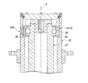
図2で説明したように、回転軸2の外周面に軸受3のボール7が転走する転走面(溝部)が形成され、回転軸2と軸受3とが一体の構成とされている場合には、回転軸2を軸受3の外輪内に緩挿した状態から、回転軸2と外輪との間にボール7を挿入する必要がある。複列のアンギュラ軸受14A、14Bにボール7を挿入するには、例えば、外輪17に径方向に貫通するボール挿入孔を形成することが考えられる。ただしこの場合、外輪17の転走面にボール挿入孔が開口するため、ボール7のスムースな転走の妨げになったり、外輪17が破損したりする可能性が考えられる。そこで、ボール7をスムースに精度よく転走させ、かつ、外輪17の破損を防止する目的で、図10のような構成としてもよい。   As described with reference to FIG. 2, a rolling surface (groove portion) on which the ball 7 of the bearing 3 rolls is formed on the outer peripheral surface of the rotating shaft 2, and the rotating shaft 2 and the bearing 3 are configured integrally. For this, it is necessary to insert the ball 7 between the rotary shaft 2 and the outer ring from the state where the rotary shaft 2 is loosely inserted into the outer ring of the bearing 3. In order to insert the balls 7 into the double row angular bearings 14A, 14B, for example, it is conceivable to form a ball insertion hole penetrating in the outer ring 17 in the radial direction. However, in this case, since the ball insertion hole is opened in the rolling surface of the outer ring 17, there is a possibility that the rolling of the ball 7 is hindered or the outer ring 17 is damaged. Therefore, the configuration shown in FIG. 10 may be used for the purpose of smoothly rolling the ball 7 with high accuracy and preventing the outer ring 17 from being damaged.

図10に示される例では、回転軸2の第2回転部材12には、複列のアンギュラ軸受14A、14Bのボール7を転走させる単列の第2溝部50が形成されている。第2溝部50は、回転軸2の外面から窪むとともに周方向に沿って延びる環状をなしており、中心軸C方向の幅が、複列のアンギュラ軸受14A、14Bに対応するように設定されているとともに、前述の第2溝部18A、18Bより広くなっている。尚、第2溝部50は、図2で説明した例のように、複列としてもよい。   In the example shown in FIG. 10, the second rotating member 12 of the rotating shaft 2 is formed with a single row of second groove portions 50 for rolling the balls 7 of the double row of angular bearings 14A, 14B. The second groove portion 50 is recessed from the outer surface of the rotating shaft 2 and has an annular shape extending in the circumferential direction, and the width in the central axis C direction is set so as to correspond to the double-row angular bearings 14A and 14B. And wider than the second groove portions 18A and 18B described above. In addition, the 2nd groove part 50 is good also as a double row like the example demonstrated in FIG.

第2溝部50における中心軸C方向に沿う一端部(図10における上端部)には、アンギュラ軸受14Aのボール7を転走させる断面円弧状の転走面50Aが形成されている。転走面50Aは、ボール7を間に挟んで、アンギュラ軸受14Aの外輪17の転走面に対向配置されている。また、第2溝部50における中心軸C方向に沿う他端部(図10における下端部)には、アンギュラ軸受14Bのボール7を転走させる断面円弧状の転走面50Bが形成されている。転走面50Bは、ボール7を間に挟んで、アンギュラ軸受14Bの外輪17の転走面に対向配置されている。   A rolling surface 50A having a circular arc cross section for rolling the ball 7 of the angular bearing 14A is formed at one end portion (upper end portion in FIG. 10) along the central axis C direction of the second groove portion 50. The rolling surface 50A is disposed opposite to the rolling surface of the outer ring 17 of the angular bearing 14A with the ball 7 interposed therebetween. Further, a rolling surface 50B having an arcuate cross section for rolling the ball 7 of the angular bearing 14B is formed at the other end portion (the lower end portion in FIG. 10) of the second groove portion 50 along the central axis C direction. The rolling surface 50B is disposed opposite to the rolling surface of the outer ring 17 of the angular bearing 14B with the ball 7 interposed therebetween.

転走面50Aと転走面50Bとは、これらの間に位置する第2溝部50の底面50Cを介して、互いに滑らかに連なっている。具体的に、底面50Cの深さ(回転軸2の外面から窪む距離)、転走面50Aの最深部の深さ及び転走面50Bの最深部の深さは、互いに同一となっている。   The rolling surface 50A and the rolling surface 50B are smoothly connected to each other via the bottom surface 50C of the second groove portion 50 located between them. Specifically, the depth of the bottom surface 50C (the distance recessed from the outer surface of the rotating shaft 2), the depth of the deepest portion of the rolling surface 50A, and the depth of the deepest portion of the rolling surface 50B are the same. .

また、ラジアル軸受13の外輪15及びアンギュラ軸受14A、14Bの外輪17は、筒状のハウジング(支持体)51の内面に径方向外方から当接されており、ラジアル軸受13及びアンギュラ軸受14A、14Bは、径方向内方の回転軸2と径方向外方のハウジング51との間に支持されている。回転軸2は、ラジアル軸受13及びアンギュラ軸受14A、14Bを介して、ハウジング51に対して中心軸C回りに回転可能であり、かつ、中心軸C方向へのスライド移動が規制されている。   The outer ring 15 of the radial bearing 13 and the outer ring 17 of the angular bearings 14A and 14B are in contact with the inner surface of a cylindrical housing (support) 51 from the outside in the radial direction, and the radial bearing 13 and the angular bearing 14A, 14 </ b> B is supported between the radially inner rotating shaft 2 and the radially outer housing 51. The rotary shaft 2 can rotate around the central axis C with respect to the housing 51 via the radial bearing 13 and the angular bearings 14A and 14B, and the sliding movement in the direction of the central axis C is restricted.

ハウジング51の内面のうち、ラジアル軸受13の外輪15に当接する部位(図10におけるハウジング51の上側部分、以下、ラジアル軸受当接部位)51Aは、アンギュラ軸受14A、14Bの外輪17に当接する部位(図10におけるハウジング51の下側部分、以下、アンギュラ軸受当接部位)51Bより、径方向内方に向けて突出して形成されている。また、ハウジング51の内面におけるアンギュラ軸受当接部位51Bの一方側(図10における上側)部分には、他方側(図10における下側)を向くとともに、アンギュラ軸受14Aの外輪17の一端面(上端面)に当接する端面51Cが形成されている。   Of the inner surface of the housing 51, a portion that contacts the outer ring 15 of the radial bearing 13 (an upper portion of the housing 51 in FIG. 10, hereinafter referred to as a radial bearing contact portion) 51A is a portion that contacts the outer ring 17 of the angular bearings 14A and 14B. (A lower portion of the housing 51 in FIG. 10, hereinafter referred to as an angular bearing contact portion) 51B is formed to protrude radially inward. Further, one side (upper side in FIG. 10) of the angular bearing contact portion 51B on the inner surface of the housing 51 faces the other side (lower side in FIG. 10), and one end surface (upper side) of the outer ring 17 of the angular bearing 14A. An end face 51 </ b> C that abuts the end face is formed.

また、回転軸2とハウジング51との間におけるアンギュラ軸受14Bの他方側には、軸受押さえ部材52が配設されている。軸受押さえ部材52は、円環板状の基部52Aと、基部52Aの一端面から立設される筒状の押さえ部52Bと、を有している。軸受押さえ部材52は、ハウジング51にボルト等により着脱可能に固定され、該軸受押さえ部材52の押さえ部52Bの一端面は、アンギュラ軸受14Bの外輪17の他端面(下端面)に当接している。また、軸受押さえ部材52の基部52Aにおいて径方向内方を向く内周面と、回転軸2の外周面との間には、若干の隙間が設けられている。   A bearing pressing member 52 is disposed on the other side of the angular bearing 14 </ b> B between the rotating shaft 2 and the housing 51. The bearing pressing member 52 has an annular plate-shaped base portion 52A and a cylindrical pressing portion 52B standing from one end surface of the base portion 52A. The bearing pressing member 52 is detachably fixed to the housing 51 with a bolt or the like, and one end surface of the pressing portion 52B of the bearing pressing member 52 is in contact with the other end surface (lower end surface) of the outer ring 17 of the angular bearing 14B. . Further, a slight gap is provided between the inner peripheral surface facing radially inward in the base portion 52 </ b> A of the bearing pressing member 52 and the outer peripheral surface of the rotating shaft 2.

そして、この変形例においては、複列のアンギュラ軸受14A、14Bの外輪17同士の間に、間座53が配設されている。間座53は、全体として例えば円環板状をなしており、周方向に分割可能、又は径方向に変形可能(例えば、周方向の一部を開口させるようにヒンジ部を介して開閉可能など)とされて、前記外輪17同士の間に着脱可能に配設されている。   In this modification, a spacer 53 is disposed between the outer rings 17 of the double row angular bearings 14A, 14B. The spacer 53 has, for example, an annular plate shape as a whole, can be divided in the circumferential direction, or can be deformed in the radial direction (for example, can be opened and closed via a hinge portion so as to open a part in the circumferential direction). And is detachably disposed between the outer rings 17.

この変形例では、アンギュラ軸受14A、14Bに下記の手順でボール7を挿入する。すなわち、アンギュラ軸受14A、14Bの外輪17の径方向外方にハウジング51が配設されていない状態、かつ、間座53が外輪17同士の間に配設されていない状態で、外輪17を中心軸C方向に移動させるとともに、該外輪17の転走面と、第2溝部50の転走面50A又は転走面50Bとの間に、外部からボール7を挿入可能な隙間を設ける。   In this modification, the ball 7 is inserted into the angular bearings 14A and 14B in the following procedure. That is, the outer ring 17 is centered in the state where the housing 51 is not disposed radially outward of the outer ring 17 of the angular bearings 14A and 14B and the spacer 53 is not disposed between the outer rings 17. While moving in the direction of the axis C, a gap is provided between the rolling surface of the outer ring 17 and the rolling surface 50A or the rolling surface 50B of the second groove 50 so that the ball 7 can be inserted from the outside.

次いで、前記隙間からボール7を挿入して、外輪17を中心軸C方向にスライド移動させるとともに該隙間を狭め、ボール7を転走面同士の間に収容した状態とする。このようにアンギュラ軸受14A、14Bの両方にボール7を挿入したら、これらアンギュラ軸受14A、14Bの外輪17同士の間に、間座53を装着する。   Next, the ball 7 is inserted through the gap, the outer ring 17 is slid in the direction of the central axis C, and the gap is narrowed so that the ball 7 is accommodated between the rolling surfaces. When the balls 7 are thus inserted into the angular bearings 14A and 14B, the spacers 53 are mounted between the outer rings 17 of the angular bearings 14A and 14B.

次いで、回転軸2に対して、中心軸C方向に沿う他方側に向けてハウジング51をスライド移動させつつ、該ハウジング51の内面をラジアル軸受13の外輪15及びアンギュラ軸受14A、14Bの外輪17に当接させて、回転軸2とハウジング51との間にラジアル軸受13及びアンギュラ軸受14A、14Bを支持させる。これにより、間座53の径方向外方がハウジング51に覆われるとともに、該間座53が外輪17同士の間から径方向外方に抜け落ちるようなことが規制される。また、ハウジング51が他方側に向けてスライド移動させられていくと、該ハウジング51の端面51Cとアンギュラ軸受14Aの外輪17の一端面とが当接させられて、それ以上の他方側へ向けたハウジング51のスライド移動が規制される。   Next, while sliding the housing 51 toward the other side along the direction of the central axis C with respect to the rotating shaft 2, the inner surface of the housing 51 is moved to the outer ring 15 of the radial bearing 13 and the outer ring 17 of the angular bearings 14A and 14B. The radial bearing 13 and the angular bearings 14 </ b> A and 14 </ b> B are supported between the rotating shaft 2 and the housing 51 by contacting each other. As a result, the outer side of the spacer 53 in the radial direction is covered with the housing 51, and the spacer 53 is restricted from falling out from between the outer rings 17 to the outer side in the radial direction. Further, when the housing 51 is slid toward the other side, the end surface 51C of the housing 51 and the one end surface of the outer ring 17 of the angular bearing 14A are brought into contact with each other and further toward the other side. The sliding movement of the housing 51 is restricted.

次いで、回転軸2とハウジング51との間に、中心軸C方向の一方側へ向けて軸受押さえ部材52を挿入するとともに、該軸受押さえ部材52の押さえ部52Bの一端面と、アンギュラ軸受14Bの外輪17の他端面とを当接させた状態で、軸受押さえ部材52をハウジング51に固定する。   Next, the bearing pressing member 52 is inserted between the rotary shaft 2 and the housing 51 toward one side in the direction of the central axis C, and one end surface of the pressing portion 52B of the bearing pressing member 52 and the angular bearing 14B are inserted. The bearing pressing member 52 is fixed to the housing 51 in a state where the other end surface of the outer ring 17 is in contact with the outer ring 17.

このように、アンギュラ軸受14Aの外輪17が、中心軸C方向の一方側からハウジング51の端面51Cに当接され、アンギュラ軸受14Bの外輪17が、中心軸C方向の他方側から軸受押さえ部材52の押さえ部52Bの一端面に当接されることにより、アンギュラ軸受14A、14Bの外輪17同士が、間座53を挟んで互いに接近した状態に維持されているとともに、中心軸C方向への相対移動が規制されている。   Thus, the outer ring 17 of the angular bearing 14A is brought into contact with the end surface 51C of the housing 51 from one side in the central axis C direction, and the outer ring 17 of the angular bearing 14B is brought into contact with the bearing holding member 52 from the other side in the central axis C direction. The outer rings 17 of the angular bearings 14A and 14B are maintained close to each other with the spacer 53 interposed therebetween, and are relatively in the direction of the central axis C. Movement is restricted.

以上説明した図10の変形例によれば、複列のアンギュラ軸受14A、14Bの外輪17を、回転軸2の第1溝部50に対して中心軸C方向にスライド移動させることによりボール7を挿入できるので、外輪17にボール挿入孔を形成する必要がない。つまり、外輪17の転走面に段差を生じさせることなく滑らかに形成できるので、ボール7をスムースに精度よく転走させることができ、かつ、外輪17の破損を防止できる。またこの構成によれば、組立の作業性がよい。   According to the modification of FIG. 10 described above, the ball 7 is inserted by sliding the outer ring 17 of the double row angular bearings 14A, 14B in the direction of the central axis C with respect to the first groove 50 of the rotary shaft 2. Therefore, it is not necessary to form a ball insertion hole in the outer ring 17. That is, since it can form smoothly without producing a level | step difference in the rolling surface of the outer ring | wheel 17, the ball | bowl 7 can be rolled smoothly and accurately, and the failure | damage of the outer ring | wheel 17 can be prevented. Moreover, according to this structure, the workability of assembly is good.

尚、図10で説明した例のように、ハウジング51の内面に、ラジアル軸受当接部位51Aとアンギュラ軸受当接部位51Bとが形成されている場合、これら当接部位51A、51Bを同一工程で加工することにより、当接部位51A、51B同士の同軸度を出すことは可能であるが、ラジアル軸受13とアンギュラ軸受14A、14Bとの同軸度については、それぞれの部品の加工精度に依存するため、精度を確保することが難しい。また、軸受3同士の同軸度を、組立時に調整することはできない。そこで、ラジアル軸受13とアンギュラ軸受14A、14Bの同軸度を精度よく設定する目的で、図11のような構成としてもよい。   In the case where the radial bearing contact portion 51A and the angular bearing contact portion 51B are formed on the inner surface of the housing 51 as in the example described with reference to FIG. 10, these contact portions 51A and 51B are formed in the same process. Although it is possible to obtain the coaxiality between the contact portions 51A and 51B by processing, the coaxiality between the radial bearing 13 and the angular bearings 14A and 14B depends on the processing accuracy of each component. It is difficult to ensure accuracy. Further, the coaxiality between the bearings 3 cannot be adjusted during assembly. Therefore, for the purpose of accurately setting the coaxiality of the radial bearing 13 and the angular bearings 14A and 14B, a configuration as shown in FIG. 11 may be adopted.

図11に示される例では、ハウジング51が、中心軸C方向に分割されて、複数の部材から構成されている。具体的に、ハウジング51は、内面にラジアル軸受当接部位51Aが形成された筒状のラジアル軸受支持部54と、内面にアンギュラ軸受当接部位51Bが形成された筒状のアンギュラ軸受支持部55と、を有している。   In the example shown in FIG. 11, the housing 51 is divided in the direction of the central axis C and is composed of a plurality of members. Specifically, the housing 51 includes a cylindrical radial bearing support portion 54 in which a radial bearing contact portion 51A is formed on the inner surface, and a cylindrical angular bearing support portion 55 in which an angular bearing contact portion 51B is formed on the inner surface. And have.

ラジアル軸受支持部54の他方側の端部には、径方向外方に突出するとともに周方向に沿って延びる環状のフランジ54Aが形成されている。また、アンギュラ軸受支持部55の一方側の端部には、径方向外方に突出するとともに周方向に沿って延びる環状のフランジ55Aが形成されている。これらフランジ54A、54Bは、ボルト等の連結部材により互いに連結されており、これにより、ラジアル軸受支持部54とアンギュラ軸受支持部55とが一体に連結されている。   An annular flange 54A that protrudes radially outward and extends in the circumferential direction is formed at the other end of the radial bearing support portion 54. In addition, an annular flange 55A that protrudes radially outward and extends along the circumferential direction is formed at one end of the angular bearing support portion 55. The flanges 54A and 54B are connected to each other by a connecting member such as a bolt, whereby the radial bearing support portion 54 and the angular bearing support portion 55 are integrally connected.

そして、この変形例では、ラジアル軸受支持部54とアンギュラ軸受支持部55とが、少なくとも径方向に相対移動可能に連結されている。すなわち、図11において、アンギュラ軸受支持部55は、ラジアル軸受支持部54に対して、符号A1で示される径方向に移動可能であり、これにより、ラジアル軸受支持部54とアンギュラ軸受支持部55との相対的なA1方向(径方向)の位置が調整可能とされている。   In this modification, the radial bearing support portion 54 and the angular bearing support portion 55 are coupled so as to be relatively movable at least in the radial direction. That is, in FIG. 11, the angular bearing support portion 55 is movable in the radial direction indicated by the reference symbol A <b> 1 with respect to the radial bearing support portion 54, whereby the radial bearing support portion 54, the angular bearing support portion 55, and the like. The relative position in the A1 direction (radial direction) can be adjusted.

また、ラジアル軸受支持部54の他端面とアンギュラ軸受支持部55の一端面との間にスペーサーを介在させたり、これら端面同士の距離をねじ作用により調整可能に構成して、軸受支持部54、55同士の中心軸C方向の相対位置を調整可能としても構わない。この場合、アンギュラ軸受支持部55は、ラジアル軸受支持部54に対して例えば符号A2で示される傾斜方向に移動可能とされる。   Further, a spacer is interposed between the other end surface of the radial bearing support portion 54 and the one end surface of the angular bearing support portion 55, or the distance between these end surfaces can be adjusted by a screw action. The relative positions of the 55 in the direction of the central axis C may be adjustable. In this case, the angular bearing support portion 55 is movable with respect to the radial bearing support portion 54 in, for example, an inclination direction indicated by reference numeral A2.

以上説明した図11の変形例によれば、ラジアル軸受当接部位51Aとアンギュラ軸受当接部位51Bとの径方向の相対位置を調整可能であるから、ハウジング51を配設する組立工程において、ラジアル軸受13とアンギュラ軸受14A、14Bの同軸度を精度よく設定(調整)できる。また、軸受3同士の同軸度が高精度に確保されるから、偏心荷重が低減されるとともに、回転軸2がスムースに回りやすくなり、発電効率が向上する。   According to the modified example of FIG. 11 described above, the radial relative position between the radial bearing contact part 51A and the angular bearing contact part 51B can be adjusted. The coaxiality between the bearing 13 and the angular bearings 14A and 14B can be set (adjusted) with high accuracy. In addition, since the coaxiality between the bearings 3 is ensured with high accuracy, the eccentric load is reduced, and the rotating shaft 2 is easily rotated smoothly, thereby improving the power generation efficiency.

また、垂直軸型風力発電装置10は、自然の風Wを受けやすい野外に設置されるものであり、軸受3のボール7や転走面に塵埃等が付着するおそれがある。また、軸受3から外部にグリースが漏れ出る可能性がある。そこで、軸受3のボール7や転走面に対して塵埃等が付着することや、軸受3からのグリース漏れを防止する目的で、図12のような構成としてもよい。   Further, the vertical axis wind power generator 10 is installed in the field where natural wind W is easily received, and there is a risk that dust or the like may adhere to the ball 7 or the rolling surface of the bearing 3. Further, grease may leak from the bearing 3 to the outside. Therefore, for the purpose of preventing dust and the like from adhering to the ball 7 and the rolling surface of the bearing 3 and preventing grease leakage from the bearing 3, a configuration as shown in FIG.

図12に示される例では、回転軸2の外周面における第2溝部50の中心軸C方向の他方側には、該外周面から窪むとともに周方向に沿って延びる環状のシール取付溝57Aが形成されている。シール取付溝57Aは、第2溝部50に接近して配置されている。また、軸受押さえ部材52の押さえ部52Bの内周面において、シール取付溝57Aより中心軸C方向の他方側に位置する部分には、該内周面から窪むとともに周方向に沿って延びる環状のシール取付溝57Bが形成されている。   In the example shown in FIG. 12, an annular seal attachment groove 57 </ b> A that is recessed from the outer peripheral surface and extends along the circumferential direction is formed on the other side of the second groove portion 50 in the central axis C direction on the outer peripheral surface of the rotating shaft 2. Has been. The seal attachment groove 57 </ b> A is disposed close to the second groove portion 50. Further, in the inner peripheral surface of the pressing portion 52B of the bearing pressing member 52, a portion located on the other side in the central axis C direction from the seal mounting groove 57A is recessed from the inner peripheral surface and extends in the circumferential direction. A seal mounting groove 57B is formed.

そして、この変形例においては、ハウジング51と回転軸2との間に、軸受3のボール7を中心軸C方向から覆うように、シール部材56が配設されている。具体的には、ハウジング51の軸受押さえ部材52と、回転軸2との間に、アンギュラ軸受14Bのボール7を中心軸C方向の他方側から覆うように、環状のシール部材56A、56Bが配設されている。   In this modification, a seal member 56 is disposed between the housing 51 and the rotary shaft 2 so as to cover the ball 7 of the bearing 3 from the direction of the central axis C. Specifically, annular seal members 56A and 56B are arranged between the bearing pressing member 52 of the housing 51 and the rotary shaft 2 so as to cover the ball 7 of the angular bearing 14B from the other side in the central axis C direction. It is installed.

シール部材56Aは、その径方向内方の部分がシール取付溝57Aに挿入されている。シール部材56Bは、その径方向外方の部分がシール取付溝57Bに挿入されている。シール部材56Aの径方向外方部分と、シール部材56Bの径方向内方部分とは、中心軸C方向に互いに重なり合うように配設されている。これらシール部材56A、56Bは、回転軸2とハウジング51との間で、該シール部材56A、56Bの一方側空間(軸受3側の空間)と他方側空間(外部空間)とを迂回させるように連通させており、これにより、シール部材56を含むラビリンス構造(迂回構造)が構成されている。   The radially inner portion of the seal member 56A is inserted into the seal attachment groove 57A. The radially outer portion of the seal member 56B is inserted into the seal attachment groove 57B. The radially outer portion of the seal member 56A and the radially inner portion of the seal member 56B are disposed so as to overlap with each other in the central axis C direction. These seal members 56A and 56B are configured to bypass the one side space (space on the bearing 3 side) and the other side space (external space) of the seal members 56A and 56B between the rotary shaft 2 and the housing 51. Thus, a labyrinth structure (a detour structure) including the seal member 56 is configured.

以上説明した図12の変形例によれば、軸受3のボール7や転走面と外部とを区画するように、ハウジング51と回転軸2との間にシール部材56A、56Bが配設されているので、外部から塵埃等が進入することが防止されるとともに、ボール7や転走面に付着することが防止されている。よって、ボール7が安定して転走し、回転軸2がスムースに回りやすくなり、発電効率が高められる。また、シール部材56A、56Bが設けられることにより、軸受3からグリースが外部に漏れ出ることが防止されるので、軸受3が長期にわたり安定して動作するとともに、メンテナンスが簡便となる。
また、前述したラビリンス構造を備えることにより、防塵効果が十分に高められ、かつ、グリース漏れを防止する効果が向上する。
12, the seal members 56A and 56B are disposed between the housing 51 and the rotary shaft 2 so as to partition the ball 7 and the rolling surface of the bearing 3 from the outside. Therefore, it is possible to prevent dust and the like from entering from the outside and adhere to the ball 7 and the rolling surface. Therefore, the ball 7 rolls stably, the rotating shaft 2 is easy to turn smoothly, and the power generation efficiency is improved. Further, since the seal members 56A and 56B are provided, the grease is prevented from leaking to the outside from the bearing 3, so that the bearing 3 operates stably over a long period of time and the maintenance becomes simple.
Further, by providing the labyrinth structure described above, the dustproof effect is sufficiently enhanced and the effect of preventing grease leakage is improved.

尚、図示の例では、シール部材56A、56Bをアンギュラ軸受14Bのボール7を中心軸C方向の他方側から覆うように配設しているが、これに限定されるものではなく、例えばシール部材56A、56Bが、ラジアル軸受13のボール7を中心軸C方向の一方側から覆うように配設されていてもよい。また、シール部材56の数量も限定されない。   In the illustrated example, the seal members 56A and 56B are disposed so as to cover the ball 7 of the angular bearing 14B from the other side in the direction of the central axis C. However, the present invention is not limited to this. 56A and 56B may be arrange | positioned so that the ball | bowl 7 of the radial bearing 13 may be covered from the one side of the central axis C direction. Further, the number of the seal members 56 is not limited.

また、図2で説明した第1実施形態では、回転軸2は、鋼材等からなり風車1に一体とされた第1回転部材11と、高炭素鋼等からなり軸受3に軸支された第2回転部材12と、を備えるとしたが、これに限定されるものではなく、図13〜図16に示される下記変形例を用いてもよい。   Further, in the first embodiment described with reference to FIG. 2, the rotating shaft 2 includes a first rotating member 11 made of steel or the like and integrated with the windmill 1, and a first rotating member 11 made of high carbon steel or the like and supported by the bearing 3. However, the present invention is not limited to this, and the following modifications shown in FIGS. 13 to 16 may be used.

図2においては、中実の棒状をなす回転軸2の第2回転部材12全体を、高炭素鋼で形成している。これは、回転軸2において、軸受3のボール7が転走する転走面に硬度が要求されるためである。しかしながら、高炭素鋼は高価であり、回転軸2の製作費用が嵩んでしまう。そこで、軸受3のボール7が回転軸2の転走面を精度よく転走しつつ、該回転軸2の製作費用を削減することを目的として、図13のような構成としてもよい。   In FIG. 2, the entire second rotating member 12 of the rotating shaft 2 having a solid bar shape is formed of high carbon steel. This is because the rotating shaft 2 requires hardness on the rolling surface on which the ball 7 of the bearing 3 rolls. However, high carbon steel is expensive, and the production cost of the rotating shaft 2 increases. Therefore, for the purpose of reducing the manufacturing cost of the rotary shaft 2 while the ball 7 of the bearing 3 rolls on the rolling surface of the rotary shaft 2 with high accuracy, the configuration shown in FIG.

図13に示される例では、回転軸2が中空のパイプ状となっている。また、回転軸2は、溶接部58により中心軸C方向に連結された転走部59及び連結部60を有する。転走部59は、例えばSCM420等の浸炭材からなり、溶接部58を防炭した上で浸炭焼入を行い形成される。また、転走部59には、その外周面における中心軸C方向の両端部の間に、転走面を有する第1溝部16又は第2溝部18A、18Bが形成されている。連結部60は、例えばSTKM等の鋼材からなり、その外周面には転走面が形成されていない。   In the example shown in FIG. 13, the rotating shaft 2 has a hollow pipe shape. The rotating shaft 2 has a rolling part 59 and a connecting part 60 that are connected in the direction of the central axis C by a welded part 58. The rolling part 59 is made of a carburized material such as SCM420, for example, and is formed by carburizing and quenching after the welded part 58 is carburized. The rolling part 59 is formed with a first groove part 16 or a second groove part 18A, 18B having a rolling surface between both ends of the outer peripheral surface in the direction of the central axis C. The connection part 60 consists of steel materials, such as STKM, for example, and the rolling surface is not formed in the outer peripheral surface.

図13の変形例によれば、回転軸2のうち、軸受3のボール7が転走する転走面以外の部位を、鋼材からなる安価な連結部60とすることができる。すなわち、軸受3のボール7が転走する転走面は高硬度に形成し、ボール7のスムースな転走を確保しつつも、回転軸2の多くの部分を鋼材で作製でき、費用削減の効果が得られる。   According to the modification of FIG. 13, a portion of the rotating shaft 2 other than the rolling surface on which the ball 7 of the bearing 3 rolls can be an inexpensive connecting portion 60 made of steel. That is, the rolling surface on which the ball 7 of the bearing 3 rolls is formed with high hardness, and while the smooth rolling of the ball 7 is ensured, many parts of the rotating shaft 2 can be made of steel, thereby reducing costs. An effect is obtained.

尚、図13で説明した例では、互いに材質の異なる転走部59と連結部60とを溶接部58で溶接し連結するため、当該溶接部58の強度を確保することが難しい。具体的に、高炭素鋼からなる転走部59は含有炭素量が多いため、溶接により強度を確保することが難しい。そこで、軸受3のボール7が回転軸2の転走面を高精度に転走しつつ、回転軸2を安価に製造でき、かつ、回転軸2の強度を確保する目的で、図14及び図15のような構成としてもよい。   In the example described with reference to FIG. 13, since the rolling part 59 and the connection part 60, which are different from each other, are welded and connected by the welding part 58, it is difficult to ensure the strength of the welding part 58. Specifically, since the rolling part 59 made of high carbon steel has a large carbon content, it is difficult to ensure the strength by welding. For this reason, the ball 7 of the bearing 3 rolls on the rolling surface of the rotary shaft 2 with high accuracy, the rotary shaft 2 can be manufactured at low cost, and the strength of the rotary shaft 2 is ensured. It is good also as a structure like 15.

図14及び図15に示される例では、回転軸2の転走部59及び連結部60が、ともにSTKM等の鋼材からなる。そして、転走部59における第1溝部16又は第2溝部18A、18Bの内面に、例えば窒化珪素等からなるセラミックス膜(高硬度膜)61が形成されている。セラミックス膜61は、例えば、第1溝部16又は第2溝部18A、18Bへの溶射により形成される。   In the example shown in FIGS. 14 and 15, both the rolling part 59 and the connecting part 60 of the rotary shaft 2 are made of steel such as STKM. A ceramic film (high hardness film) 61 made of, for example, silicon nitride is formed on the inner surface of the first groove portion 16 or the second groove portions 18A and 18B in the rolling portion 59. The ceramic film 61 is formed, for example, by thermal spraying on the first groove portion 16 or the second groove portions 18A and 18B.

図14及び図15の変形例によれば、回転軸2のうち、軸受3のボール7が転走する転走面以外の部位を、安価な鋼材で作製できる。すなわち、軸受3のボール7が転走する転走面はヤング率の高いセラミックス膜61により形成し、ボール7のスムースな転走を確保しつつも、それ以外の回転軸2の大部分を鋼材で作製でき、費用削減の効果が得られる。さらに、転走部59と連結部60が、ともに鋼材からなるので、溶接部58の強度が十分に確保されるとともに、回転軸2の強度が確保される。   14 and 15, parts of the rotating shaft 2 other than the rolling surface on which the ball 7 of the bearing 3 rolls can be made of an inexpensive steel material. That is, the rolling surface on which the ball 7 of the bearing 3 rolls is formed of a ceramic film 61 having a high Young's modulus, and while the smooth rolling of the ball 7 is ensured, most of the other rotating shaft 2 is made of steel. Can be manufactured with a cost reduction effect. Furthermore, since both the rolling part 59 and the connection part 60 are made of steel, the strength of the welded part 58 is sufficiently secured and the strength of the rotating shaft 2 is secured.

尚、軸受3のボール7の転走をより高精度に行い、回転軸2の強度を高め、かつ、生産性を向上させることを目的として、図14で説明した例に代えて、図16の構成としてもよい。   For the purpose of performing the rolling of the ball 7 of the bearing 3 with higher accuracy, increasing the strength of the rotating shaft 2 and improving the productivity, the example shown in FIG. It is good also as a structure.

図16に示される例では、回転軸2は、溶接部58により連結される転走部59と連結部60とを有していない。すなわち、回転軸2全体が、鋼材により一体に形成されている。そして、回転軸2の外周面に形成された第1溝部16又は第2溝部18A、18Bの内面に、セラミックス膜61が溶射されている。   In the example shown in FIG. 16, the rotating shaft 2 does not have the rolling part 59 and the connecting part 60 connected by the weld part 58. That is, the entire rotating shaft 2 is integrally formed of a steel material. The ceramic film 61 is sprayed on the inner surface of the first groove portion 16 or the second groove portions 18A and 18B formed on the outer peripheral surface of the rotating shaft 2.

図16の変形例によれば、前述した図14の変形例と同様の効果が得られつつ、軸受3のボール7の転走をより高精度に行うことができ(ラジアル軸受13とアンギュラ軸受14A、14Bの同軸度を出しやすい)、回転軸2の強度を高めることができ、かつ、生産性を向上できる。   According to the modification of FIG. 16, the ball 7 of the bearing 3 can be rolled with higher accuracy while obtaining the same effect as that of the modification of FIG. 14 described above (the radial bearing 13 and the angular bearing 14A). 14B), the strength of the rotating shaft 2 can be increased, and the productivity can be improved.

その他、本発明の前述の実施形態及び変形例で説明した構成要素を、適宜組み合わせても構わない。また、本発明の趣旨を逸脱しない範囲において、前述の構成要素を周知の構成要素に置き換えることも可能である。   In addition, you may combine suitably the component demonstrated in the above-mentioned embodiment and modification of this invention. In addition, the above-described components can be replaced with well-known components without departing from the spirit of the present invention.

1…風車、 1A…ブレード、 2、32…回転軸(軸体)、 3…軸受、 4…ケーシング(支持体)、 5…発電機、 7…ボール(転動体)、 10、20、30…垂直軸型風力発電装置(垂直軸型流体発電装置)、 13、23、33…ラジアル軸受、 14A、14B、24A、24B、34A、34B…アンギュラ軸受、 16、26、36…第1溝部、 18A、18B、28A、28B、38A、38B、50…第2溝部、 31…支持軸(支持体)、 51…ハウジング(支持体)、 C…中心軸、 W…風(作動流体)。 DESCRIPTION OF SYMBOLS 1 ... Windmill, 1A ... Blade, 2, 32 ... Rotary shaft (shaft body), 3 ... Bearing, 4 ... Casing (support body), 5 ... Generator, 7 ... Ball (rolling body), 10, 20, 30 ... Vertical shaft type wind power generation device (vertical shaft type fluid power generation device), 13, 23, 33 ... radial bearing, 14A, 14B, 24A, 24B, 34A, 34B ... angular bearing, 16, 26, 36 ... first groove, 18A , 18B, 28A, 28B, 38A, 38B, 50 ... second groove portion, 31 ... support shaft (support), 51 ... housing (support), C ... central shaft, W ... wind (working fluid).

Claims (1)

軸体と、
前記軸体の中心軸回りに間隔をあけて配列される複数のブレードと、
前記軸体の中心軸方向に沿う一方側に複数の前記ブレードを接続する複数のアームと、
前記軸体の中心軸方向に沿う他方側に配設され、前記軸体が周方向に回転することで得られる機械エネルギーを電気エネルギーに変換して電力を発電させる発電機と、
前記軸体の中心軸方向における前記アームと前記発電機との間で、軸受を介して前記軸体を前記中心軸回りに回転可能に片持ち支持する支持体と、を備えた垂直軸型流体発電装置であって、
前記軸受は、単列のラジアル軸受と、複列のアンギュラ軸受と、を含み、
前記軸体には、複列の前記アンギュラ玉軸受の転動体を転走させる溝部が形成され、
前記支持体には、前記アンギュラ玉軸受の転動体を挟んで前記溝部に対向して、該アンギュラ玉軸受の外輪が設けられており、
単列の前記ラジアル玉軸受は、前記他方側に配設され、
複列の前記アンギュラ玉軸受は、前記一方側に配設されることを特徴とする垂直軸型流体発電装置。
A shaft,
A plurality of blades arranged at intervals around the central axis of the shaft body;
A plurality of arms connecting the plurality of blades on one side along the central axis direction of the shaft body;
A generator that is disposed on the other side along the central axis direction of the shaft body and converts the mechanical energy obtained by rotating the shaft body in the circumferential direction into electric energy to generate electric power;
A vertical shaft fluid comprising: a support body that cantileverably supports the shaft body around the central axis via a bearing between the arm and the generator in the central axis direction of the shaft body A power generator,
The bearing includes a radial ball bearing of a single row, the angular contact ball bearing with double row, only including,
The shaft body is formed with a groove for rolling the rolling elements of the double-row angular ball bearing,
The support body is provided with an outer ring of the angular ball bearing so as to face the groove portion across the rolling element of the angular ball bearing,
The single-row radial ball bearing is disposed on the other side,
The vertical axis type fluid power generation device according to claim 1, wherein the double-row angular ball bearings are disposed on the one side .
JP2011129277A 2010-06-11 2011-06-09 Vertical axis fluid power generator Active JP5845003B2 (en)

Priority Applications (1)

Application Number Priority Date Filing Date Title
JP2011129277A JP5845003B2 (en) 2010-06-11 2011-06-09 Vertical axis fluid power generator

Applications Claiming Priority (3)

Application Number Priority Date Filing Date Title
JP2010134261 2010-06-11
JP2011129277A JP5845003B2 (en) 2010-06-11 2011-06-09 Vertical axis fluid power generator

Publications (3)

Publication Number Publication Date
JP2012017736A JP2012017736A (en) 2012-01-26
JP2012017736A5 JP2012017736A5 (en) 2014-07-24
JP5845003B2 true JP5845003B2 (en) 2016-01-20

Family

ID=45603153

Family Applications (1)

Application Number Title Priority Date Filing Date
JP2011129277A Active JP5845003B2 (en) 2010-06-11 2011-06-09 Vertical axis fluid power generator

Country Status (1)

Country Link
JP (1) JP5845003B2 (en)

Families Citing this family (8)

* Cited by examiner, † Cited by third party
Publication number Priority date Publication date Assignee Title
JP2013210059A (en) * 2012-03-30 2013-10-10 National Institute Of Advanced Industrial Science & Technology Rotary shaft supporting mechanism and rotation introducing mechanism
JP5620941B2 (en) 2012-04-26 2014-11-05 Thk株式会社 Rotating shaft device of vertical axis type fluid power generation device and vertical shaft type fluid power generation device
JP6130680B2 (en) * 2013-02-12 2017-05-17 Thk株式会社 Vertical axis fluid power generator
JP6418477B2 (en) * 2013-10-01 2018-11-07 Thk株式会社 Impeller support device and vertical axis fluid power generation device
JP7109948B2 (en) * 2018-03-19 2022-08-01 セイコーインスツル株式会社 Vibration generator and electronic equipment
CN108331723A (en) * 2018-03-22 2018-07-27 许占欣 A kind of magnetic suspending wind turbine generator oil immersed type multiple bearing combination shaft
DE102018112330A1 (en) * 2018-05-23 2019-11-28 Schaeffler Technologies AG & Co. KG Double row angular contact ball bearing and method for adjusting the bearing
JP7319087B2 (en) * 2019-05-13 2023-08-01 Thk株式会社 Rotating electric machine and in-wheel motor using this rotating electric machine

Family Cites Families (6)

* Cited by examiner, † Cited by third party
Publication number Priority date Publication date Assignee Title
DE7614054U1 (en) * 1976-05-04 1976-08-26 Skf Kugellagerfabriken Gmbh, 8720 Schweinfurt OUTDOOR MOTOR
JPS63111315A (en) * 1986-10-29 1988-05-16 Hisashi Kobayashi Ceramics ball bearing
JP2005061218A (en) * 2003-06-09 2005-03-10 Shinko Electric Co Ltd Vertical axis wind turbine generator
CN1938517A (en) * 2004-03-31 2007-03-28 株式会社Ipb Cantilevered vertical shaft type windmill
JP2007139014A (en) * 2005-11-16 2007-06-07 Nsk Ltd Angular ball bearing and nut-rotatable ball screw device
JP2007333117A (en) * 2006-06-15 2007-12-27 Ntn Corp Bearing unit for driving wheel

Also Published As

Publication number Publication date
JP2012017736A (en) 2012-01-26

Similar Documents

Publication Publication Date Title
JP5845003B2 (en) Vertical axis fluid power generator
JP5509183B2 (en) Vertical axis wind turbine bearing and vertical axis wind power generator
US20110110770A1 (en) Hydroelectric turbine having a magnetic bearing
JP5557392B2 (en) Fixing structure of the generator shaft of the outer rotor coreless type wind power generator
US20130049372A1 (en) Main bearing for a wind turbine
WO2013161566A1 (en) Rotary shaft device and vertical shaft fluid power generator
JP2008064248A (en) Rolling bearing cage, rolling bearing, and spindle supporting structure for wind power generator
JP5543371B2 (en) Coaxial reversal type coreless generator
US9124153B2 (en) Direct drive generator
JP2012017736A5 (en)
CN111133192A (en) Wind turbine
JP2008069691A (en) Windmill device for power generation and wind power generating device
EP1657437A1 (en) Generator bearing arrangement in a wind power plant
JP6418477B2 (en) Impeller support device and vertical axis fluid power generation device
JP2007132418A (en) Spindle supporting structure for wind power generator
US10495069B2 (en) Stabilizing a wind turbine assembly
CN111322201B (en) Direct-drive wind generating set
JP2023041577A (en) Rotational shaft lower end support structure of vertical axis wind turbine
JP2017180232A (en) Air turbine device
JP5719416B2 (en) Design method for vertical axis wind turbine bearings
JP2011043171A (en) Floating shaft support structure of rotating body
JP2006090345A (en) Double row automatic aligning roller bearing and main shaft supporting structure of wind power generator
JP2005127209A (en) Vertical shaft type wind power generator
JP2007170332A (en) Wind power generation device

Legal Events

Date Code Title Description
A521 Request for written amendment filed

Free format text: JAPANESE INTERMEDIATE CODE: A523

Effective date: 20140609

A621 Written request for application examination

Free format text: JAPANESE INTERMEDIATE CODE: A621

Effective date: 20140609

A977 Report on retrieval

Free format text: JAPANESE INTERMEDIATE CODE: A971007

Effective date: 20150311

A131 Notification of reasons for refusal

Free format text: JAPANESE INTERMEDIATE CODE: A131

Effective date: 20150401

A521 Request for written amendment filed

Free format text: JAPANESE INTERMEDIATE CODE: A523

Effective date: 20150519

TRDD Decision of grant or rejection written
A01 Written decision to grant a patent or to grant a registration (utility model)

Free format text: JAPANESE INTERMEDIATE CODE: A01

Effective date: 20151104

A61 First payment of annual fees (during grant procedure)

Free format text: JAPANESE INTERMEDIATE CODE: A61

Effective date: 20151120

R150 Certificate of patent or registration of utility model

Ref document number: 5845003

Country of ref document: JP

Free format text: JAPANESE INTERMEDIATE CODE: R150

R250 Receipt of annual fees

Free format text: JAPANESE INTERMEDIATE CODE: R250

R250 Receipt of annual fees

Free format text: JAPANESE INTERMEDIATE CODE: R250

R250 Receipt of annual fees

Free format text: JAPANESE INTERMEDIATE CODE: R250

R250 Receipt of annual fees

Free format text: JAPANESE INTERMEDIATE CODE: R250

R250 Receipt of annual fees

Free format text: JAPANESE INTERMEDIATE CODE: R250

R250 Receipt of annual fees

Free format text: JAPANESE INTERMEDIATE CODE: R250