JP5844225B2 - Internal EGR amount calculation device for internal combustion engine - Google Patents
Internal EGR amount calculation device for internal combustion engine Download PDFInfo
- Publication number
- JP5844225B2 JP5844225B2 JP2012151237A JP2012151237A JP5844225B2 JP 5844225 B2 JP5844225 B2 JP 5844225B2 JP 2012151237 A JP2012151237 A JP 2012151237A JP 2012151237 A JP2012151237 A JP 2012151237A JP 5844225 B2 JP5844225 B2 JP 5844225B2
- Authority
- JP
- Japan
- Prior art keywords
- amount
- gas
- valve
- cylinder
- timing
- Prior art date
- Legal status (The legal status is an assumption and is not a legal conclusion. Google has not performed a legal analysis and makes no representation as to the accuracy of the status listed.)
- Expired - Fee Related
Links
Images


Classifications
-
- F—MECHANICAL ENGINEERING; LIGHTING; HEATING; WEAPONS; BLASTING
- F02—COMBUSTION ENGINES; HOT-GAS OR COMBUSTION-PRODUCT ENGINE PLANTS
- F02M—SUPPLYING COMBUSTION ENGINES IN GENERAL WITH COMBUSTIBLE MIXTURES OR CONSTITUENTS THEREOF
- F02M26/00—Engine-pertinent apparatus for adding exhaust gases to combustion-air, main fuel or fuel-air mixture, e.g. by exhaust gas recirculation [EGR] systems
- F02M26/01—Internal exhaust gas recirculation, i.e. wherein the residual exhaust gases are trapped in the cylinder or pushed back from the intake or the exhaust manifold into the combustion chamber without the use of additional passages
-
- F—MECHANICAL ENGINEERING; LIGHTING; HEATING; WEAPONS; BLASTING
- F02—COMBUSTION ENGINES; HOT-GAS OR COMBUSTION-PRODUCT ENGINE PLANTS
- F02D—CONTROLLING COMBUSTION ENGINES
- F02D13/00—Controlling the engine output power by varying inlet or exhaust valve operating characteristics, e.g. timing
- F02D13/02—Controlling the engine output power by varying inlet or exhaust valve operating characteristics, e.g. timing during engine operation
- F02D13/0261—Controlling the valve overlap
- F02D13/0265—Negative valve overlap for temporarily storing residual gas in the cylinder
-
- Y—GENERAL TAGGING OF NEW TECHNOLOGICAL DEVELOPMENTS; GENERAL TAGGING OF CROSS-SECTIONAL TECHNOLOGIES SPANNING OVER SEVERAL SECTIONS OF THE IPC; TECHNICAL SUBJECTS COVERED BY FORMER USPC CROSS-REFERENCE ART COLLECTIONS [XRACs] AND DIGESTS
- Y02—TECHNOLOGIES OR APPLICATIONS FOR MITIGATION OR ADAPTATION AGAINST CLIMATE CHANGE
- Y02T—CLIMATE CHANGE MITIGATION TECHNOLOGIES RELATED TO TRANSPORTATION
- Y02T10/00—Road transport of goods or passengers
- Y02T10/10—Internal combustion engine [ICE] based vehicles
- Y02T10/12—Improving ICE efficiencies
Description
本発明は、内燃機関の内部EGR量を算出する内燃機関の内部EGR量算出装置に関する。 The present invention relates to an internal EGR amount calculation device for an internal combustion engine that calculates an internal EGR amount of the internal combustion engine.
従来、内燃機関の内部EGR量算出装置として、特許文献1に記載されたものが知られている。この内部EGR量算出装置では、残留既燃ガス量に吹き返しガス量を加算することにより、内部EGR量が算出される。この残留既燃ガス量は、気筒内に残留する既燃ガス量であり、具体的には、気体の状態方程式により、筒内容積などを用いて算出される。
Conventionally, as an internal EGR amount calculation device for an internal combustion engine, one described in
また、吹き返しガス量は、バルブオーバーラップ期間中、吸気通路と排気通路の間での圧力差に起因して、既燃ガスが排気通路から吸気通路側に一旦流れた後、気筒内に吹き返された既燃ガスの量を表している。この吹き返しガス量は、既燃ガスが流れる流路をノズルと見なし、ノズルの方程式を用いて算出される。 In addition, the amount of blowback gas is blown back into the cylinder after the burned gas once flows from the exhaust passage to the intake passage due to the pressure difference between the intake passage and the exhaust passage during the valve overlap period. Represents the amount of burnt gas. The amount of blown-back gas is calculated using the nozzle equation, assuming that the flow path through which the burned gas flows is a nozzle.
このノズルの方程式は、有効開口面積の時間積分値Σ(μA)を含んでいる。この有効開口面積の時間積分値Σ(μA)は、具体的には、有効開口面積をクランク角について積分することにより、クランク角積分値f1(OL)を算出し、これを機関回転数NEで除算することによって算出される。 This nozzle equation includes the time integral value Σ (μA) of the effective opening area. Specifically, the time integral value Σ (μA) of the effective opening area is calculated by integrating the effective opening area with respect to the crank angle to calculate the crank angle integrated value f1 (OL), which is calculated by the engine speed NE. Calculated by dividing.
一般に、内燃機関の場合、吸気弁および/または排気弁のバルブタイミングが変更されると、吸気弁および排気弁の開弁期間中において気筒内から流出入するガス量(以下「筒内流出入ガス量」という)が変化することになる。これに対して、特許文献1の内部EGR量算出装置の場合、このようなバルブタイミングの変更に伴う筒内流出入ガス量の変化を考慮することなく、バルブオーバーラップ期間中の吹き返しガス量しか考慮していない。そのため、バルブタイミングの変更によって筒内流出入ガス量が変化したときに、その影響によって内部EGR量の算出精度が低下してしまうことになる。これに加えて、吹き返しガス量の算出式が有効開口面積の時間積分値Σ(μA)を含んでいる関係上、この有効開口面積の時間積分値Σ(μA)を算出する際、有効開口面積をクランク角について積分する必要があるので、その分、演算負荷が高くなってしまう。
Generally, in the case of an internal combustion engine, when the valve timing of the intake valve and / or the exhaust valve is changed, the amount of gas flowing in and out of the cylinder during the opening period of the intake valve and the exhaust valve (hereinafter referred to as “cylinder inflow / outflow gas”). Will change). On the other hand, in the case of the internal EGR amount calculation device of
本発明は、上記課題を解決するためになされたもので、吸気弁および/または排気弁のバルブタイミングが変更されたときでも、それに応じて内部EGR量を適切かつ容易に算出することができ、内部EGR量の算出精度を向上させることができる内燃機関の内部EGR量算出装置を提供することを目的とする。 The present invention has been made to solve the above problems, and even when the valve timing of the intake valve and / or the exhaust valve is changed, the internal EGR amount can be appropriately and easily calculated accordingly. An object of the present invention is to provide an internal EGR amount calculation device for an internal combustion engine that can improve the calculation accuracy of the internal EGR amount.
上記目的を達成するために、請求項1に係る発明は、吸気弁4および排気弁5の少なくとも一方のバルブタイミングを変更することによって、気筒3a内に残留する既燃ガス量である内部EGR量が変更されるとともに、とともに、バルブタイミングの変更状態にかかわらず、1燃焼サイクル中にバルブオーバーラップが発生するように構成された内燃機関3の内部EGR量算出装置1であって、バルブタイミングを取得するバルブタイミング取得手段(ECU2、クランク角センサ30、吸気カム角センサ36、排気カム角センサ37)と、バルブタイミングが所定の基準タイミングにあるときに気筒3a内に残留する既燃ガス量である基準筒内ガス量(基準内部EGR量GEGR1_0)を算出する基準筒内ガス量算出手段(ECU2、ステップ2)と、バルブタイミングに応じて、吸気弁4および排気弁5の開弁期間中において気筒3a内に流出入する既燃ガスの、バルブタイミングが所定の基準タイミングにあるときの流出入量に対する変化量を流出入ガス変化量(内部EGR増減量DGEGR1)として算出する流出入ガス変化量算出手段(ECU2、ステップ9)と、基準筒内ガス量(基準内部EGR量GEGR1_0)に流出入ガス変化量(内部EGR増減量DGEGR1)を加算することにより、内部EGR量GEGR1を算出する内部EGR量算出手段(ECU2、ステップ10)と、を備えることを特徴とする。
In order to achieve the above object, the invention according to
この内燃機関の内部EGR量算出装置によれば、基準筒内ガス量および流出入ガス変化量に基づき、内部EGR量が算出される。この場合、流出入ガス変化量は、バルブタイミングに応じて、吸気弁および排気弁の開弁期間中において気筒内に流出入する既燃ガスの、バルブタイミングが所定の基準タイミングにあるときの流出入量に対する変化量として算出される。一方、基準筒内ガス量は、バルブタイミングが所定の基準タイミングにあるときに気筒内に残留する既燃ガス量であるので、この基準筒内ガス量に上述した流出入ガス変化量を加算することにより、内部EGR量を算出することによって、バルブタイミングの変更に伴う気筒内に流出入する既燃ガス量の変化を反映させながら、内部EGR量を適切にかつ精度よく算出することができる。それにより、内部EGR量の算出精度を向上させることができる。 According to the internal EGR amount calculation device for an internal combustion engine, the internal EGR amount is calculated based on the reference in-cylinder gas amount and the inflow / outflow gas change amount. In this case, the amount of change in the inflow / outflow gas is determined according to the valve timing when the burned gas flowing into and out of the cylinder during the opening period of the intake valve and the exhaust valve when the valve timing is at a predetermined reference timing. It is calculated as the amount of change with respect to the input amount. On the other hand, reference in-cylinder gas amount are the amount of burned gas remaining in the cylinder when the valve timing is at a predetermined reference timing, adds the inflow and outflow gas change amount described above to the reference in-cylinder gas amount by, thus to calculate the internal EGR amount, while reflecting a change in the amount of burned gas to and from the flow into the cylinder due to the change of the valve timing can be calculated appropriately and accurately the internal EGR amount . Thereby, the calculation accuracy of the internal EGR amount can be improved.
請求項2に係る発明は、吸気弁4および排気弁5の少なくとも一方のバルブタイミングを変更することによって、気筒3a内に残留する既燃ガス量である内部EGR量が変更される内燃機関3の内部EGR量算出装置1であって、バルブタイミングを取得するバルブタイミング取得手段(ECU2、クランク角センサ30、吸気カム角センサ36、排気カム角センサ37)と、バルブタイミングが所定の基準タイミングにあるときに気筒3a内に残留する既燃ガス量である基準筒内ガス量(基準内部EGR量GEGR1_0)を算出する基準筒内ガス量算出手段(ECU2、ステップ2)と、バルブタイミングに応じて、吸気弁4および排気弁5の開弁期間中において気筒3a内に流出入する既燃ガスの、バルブタイミングが所定の基準タイミングにあるときの流出入量に対する変化量を流出入ガス変化量(内部EGR増減量DGEGR1)として算出する流出入ガス変化量算出手段(ECU2、ステップ9)と、基準筒内ガス量(基準内部EGR量GEGR1_0)および流出入ガス変化量(内部EGR増減量DGEGR1)に基づき、内部EGR量GEGR1を算出する内部EGR量算出手段(ECU2、ステップ10)と、を備え、吸気弁4のバルブタイミングが変更可能に構成されており、バルブタイミング取得手段は、吸気弁4のバルブタイミング(吸気カム位相CAIN)を取得し、吸気弁4のバルブタイミング(吸気カム位相CAIN)に基づき、気筒3a内から流出する既燃ガス量の、吸気弁4のバルブタイミングが所定の基準タイミングにあるときの値に対する変化分を流出ガス変化量(流出ガス増大量DGEGR1_IN)として算出する流出ガス変化量算出手段(ECU2、ステップ3,4,7)をさらに備え、流出入ガス変化量算出手段は、流出ガス変化量(流出ガス増大量DGEGR1_IN)に基づき、流出入ガス変化量(内部EGR増減量DGEGR1)を算出することを特徴とする。In the invention according to
この内燃機関の内部EGR量算出装置によれば、基準筒内ガス量および流出入ガス変化量に基づき、内部EGR量が算出される。この場合、流出入ガス変化量は、バルブタイミングに応じて、吸気弁および排気弁の開弁期間中において気筒内に流出入する既燃ガスの、バルブタイミングが所定の基準タイミングにあるときの流出入量に対する変化量として算出される。一方、基準筒内ガス量は、バルブタイミングが所定の基準タイミングにあるときに気筒内に残留する既燃ガス量であるので、この基準筒内ガス量と上述した流出入ガス変化量に基づいて、内部EGR量を算出することにより、バルブタイミングの変更に伴う気筒内に流出入する既燃ガス量の変化を反映させながら、内部EGR量を適切にかつ精度よく算出することができる。さらに、吸気弁のバルブタイミングに基づき、気筒内から流出する既燃ガス量の、吸気弁のバルブタイミングが所定の基準タイミングにあるときの値に対する変化分が、流出ガス変化量として算出され、流出ガス変化量に基づき、流出入ガス変化量が算出されるとともに、基準筒内ガス量および流出入ガス変化量に基づき、内部EGR量が算出される。この場合、基準筒内ガス量は、吸気弁のバルブタイミングが所定の基準タイミングにあるときに気筒内に残留する既燃ガス量であり、流出ガス変化量は吸気弁のバルブタイミングに基づいて算出されるので、基準筒内ガス量、流出ガス変化量、流出入ガス変化量および内部EGR量を1回の算出処理で算出することができる。それにより、積分演算処理を必要とする特許文献1の算出手法と比べて、内部EGR量を容易に算出することができ、内部EGR量を算出する際の演算負荷を低減することができる。その結果、商品性を向上させることができる。According to the internal EGR amount calculation device for an internal combustion engine, the internal EGR amount is calculated based on the reference in-cylinder gas amount and the inflow / outflow gas change amount. In this case, the amount of change in the inflow / outflow gas is determined according to the valve timing when the burned gas flowing into and out of the cylinder during the opening period of the intake valve and the exhaust valve when the valve timing is at a predetermined reference timing. It is calculated as the amount of change with respect to the input amount. On the other hand, the reference in-cylinder gas amount is the amount of burnt gas remaining in the cylinder when the valve timing is at the predetermined reference timing, and therefore, based on this reference in-cylinder gas amount and the above-described inflow / outflow gas change amount. By calculating the internal EGR amount, the internal EGR amount can be calculated appropriately and accurately while reflecting the change in the amount of burned gas flowing into and out of the cylinder accompanying the change in valve timing. Furthermore, based on the valve timing of the intake valve, the amount of change in the amount of burned gas flowing out of the cylinder with respect to the value when the valve timing of the intake valve is at a predetermined reference timing is calculated as the outflow gas change amount. An inflow / outflow gas change amount is calculated based on the gas change amount, and an internal EGR amount is calculated based on the reference in-cylinder gas amount and the inflow / outflow gas change amount. In this case, the reference in-cylinder gas amount is the amount of burnt gas remaining in the cylinder when the valve timing of the intake valve is at a predetermined reference timing, and the change in outflow gas is calculated based on the valve timing of the intake valve. Therefore, the reference in-cylinder gas amount, the outflow gas change amount, the outflow / ingress gas change amount, and the internal EGR amount can be calculated in one calculation process. Thereby, compared with the calculation method of
請求項3に係る発明は、吸気弁4および排気弁5の少なくとも一方のバルブタイミングを変更することによって、気筒3a内に残留する既燃ガス量である内部EGR量が変更される内燃機関3の内部EGR量算出装置1であって、バルブタイミングを取得するバルブタイミング取得手段(ECU2、クランク角センサ30、吸気カム角センサ36、排気カム角センサ37)と、バルブタイミングが所定の基準タイミングにあるときに気筒3a内に残留する既燃ガス量である基準筒内ガス量(基準内部EGR量GEGR1_0)を算出する基準筒内ガス量算出手段(ECU2、ステップ2)と、バルブタイミングに応じて、吸気弁4および排気弁5の開弁期間中において気筒3a内に流出入する既燃ガスの、バルブタイミングが所定の基準タイミングにあるときの流出入量に対する変化量を流出入ガス変化量(内部EGR増減量DGEGR1)として算出する流出入ガス変化量算出手段(ECU2、ステップ9)と、基準筒内ガス量(基準内部EGR量GEGR1_0)および流出入ガス変化量(内部EGR増減量DGEGR1)に基づき、内部EGR量GEGR1を算出する内部EGR量算出手段(ECU2、ステップ10)と、を備え、吸気弁4および排気弁5の双方のバルブタイミングが変更可能に構成されており、バルブタイミング取得手段は、吸気弁4および排気弁5の双方のバルブタイミング(吸気カム位相CAIN、排気カム位相CAEX)を取得し、吸気弁4のバルブタイミング(吸気カム位相CAIN)に基づき、気筒3a内から流出する既燃ガス量の、吸気弁4のバルブタイミングが所定の基準タイミングにあるときの値に対する変化分を流出ガス変化量(流出ガス増大量DGEGR1_IN)として算出する流出ガス変化量算出手段(ECU2、ステップ3,4,7)と、排気弁5のバルブタイミング(排気カム位相CAEX)に基づき、気筒3a内に流入する既燃ガス量の、排気弁5のバルブタイミングが所定の基準タイミングにあるときの値に対する変化分を流入ガス変化量(流入ガス増大量DGEGR1_EX)として算出する流入ガス変化量算出手段(ECU2、ステップ5,6,8)と、をさらに備え、流出入ガス変化量算出手段は、流出ガス変化量(流出ガス増大量DGEGR1_IN)および流入ガス変化量(流入ガス増大量DGEGR1_EX)に基づき、流出入ガス変化量(内部EGR増減量DGEGR1)を算出する(ステップ9)ことを特徴とする。According to the third aspect of the invention, the internal EGR amount, which is the amount of burnt gas remaining in the
この内燃機関の内部EGR量算出装置によれば、基準筒内ガス量および流出入ガス変化量に基づき、内部EGR量が算出される。この場合、流出入ガス変化量は、バルブタイミングに応じて、吸気弁および排気弁の開弁期間中において気筒内に流出入する既燃ガスの、バルブタイミングが所定の基準タイミングにあるときの流出入量に対する変化量として算出される。一方、基準筒内ガス量は、バルブタイミングが所定の基準タイミングにあるときに気筒内に残留する既燃ガス量であるので、この基準筒内ガス量と上述した流出入ガス変化量に基づいて、内部EGR量を算出することにより、バルブタイミングの変更に伴う気筒内に流出入する既燃ガス量の変化を反映させながら、内部EGR量を適切にかつ精度よく算出することができる。さらに、吸気弁のバルブタイミングに基づき、気筒内から流出する既燃ガス量の、吸気弁のバルブタイミングが所定の基準タイミングにあるときの値に対する変化分が、流出ガス変化量として算出され、排気弁のバルブタイミングに基づき、気筒内に流入する既燃ガス量の、排気弁のバルブタイミングが所定の基準タイミングにあるときの値に対する変化分が、流入ガス変化量として算出されるとともに、流出ガス変化量および流入ガス変化量に基づき、流出入ガス変化量が算出される。この場合、基準筒内ガス量は、吸気弁および排気弁のバルブタイミングが所定の基準タイミングにあるときに気筒内に残留する既燃ガス量であり、流出ガス変化量および流入ガス変化量はそれぞれ、吸気弁および排気弁のバルブタイミングに基づいて算出されるので、基準筒内ガス量、流出ガス変化量、流入ガス変化量、流出入ガス変化量および内部EGR量を1回の算出処理で算出することができる。それにより、積分演算処理を必要とする特許文献1の算出手法と比べて、内部EGR量を容易に算出することができ、内部EGR量を算出する際の演算負荷を低減することができる。その結果、商品性を向上させることができる。According to the internal EGR amount calculation device for an internal combustion engine, the internal EGR amount is calculated based on the reference in-cylinder gas amount and the inflow / outflow gas change amount. In this case, the amount of change in the inflow / outflow gas is determined according to the valve timing when the burned gas flowing into and out of the cylinder during the opening period of the intake valve and the exhaust valve when the valve timing is at a predetermined reference timing. It is calculated as the amount of change with respect to the input amount. On the other hand, the reference in-cylinder gas amount is the amount of burnt gas remaining in the cylinder when the valve timing is at the predetermined reference timing, and therefore, based on this reference in-cylinder gas amount and the above-described inflow / outflow gas change amount. By calculating the internal EGR amount, the internal EGR amount can be calculated appropriately and accurately while reflecting the change in the amount of burned gas flowing into and out of the cylinder accompanying the change in valve timing. Further, based on the valve timing of the intake valve, the amount of change in the amount of burned gas flowing out from the cylinder with respect to the value when the valve timing of the intake valve is at a predetermined reference timing is calculated as the amount of change in exhaust gas, Based on the valve timing of the valve, the amount of change in the amount of burnt gas flowing into the cylinder with respect to the value when the valve timing of the exhaust valve is at a predetermined reference timing is calculated as the inflow gas change amount, and the outflow gas Based on the change amount and the inflow gas change amount, the outflow / inflow gas change amount is calculated. In this case, the reference in-cylinder gas amount is the amount of burnt gas remaining in the cylinder when the valve timing of the intake valve and the exhaust valve is at a predetermined reference timing, and the outflow gas change amount and the inflow gas change amount are respectively Since it is calculated based on the valve timing of the intake valve and the exhaust valve, the reference cylinder gas amount, outflow gas change amount, inflow gas change amount, inflow / outflow gas change amount and internal EGR amount are calculated in one calculation process can do. Thereby, compared with the calculation method of
請求項4に係る発明は、請求項1ないし3のいずれかに記載の内燃機関3の内部EGR量算出装置1において、内燃機関3の排気通路9内の排ガスの温度である排気温Texを取得する排気温取得手段(排気温センサ35)と、内燃機関3の排気通路9内の排ガスの圧力である排気圧Pexを取得する排気圧取得手段(排気圧センサ34)と、バルブタイミングが所定の基準タイミングにあるときの気筒3aの容積である基準筒内容積Vcylin_0を取得する基準筒内容積取得手段(ECU2、ステップ1)と、をさらに備え、基準筒内ガス量算出手段は、排気温Tex、排気圧Pexおよび基準筒内容積Vcylin_0に基づき、気体の状態方程式(式(1))を用いることによって、基準筒内ガス量(基準内部EGR量GEGR1_0)を算出することを特徴とする。According to a fourth aspect of the invention, in the internal EGR
この内燃機関の内部EGR量算出装置によれば、基準筒内ガス量が、排気温、排気圧および基準筒内容積に基づき、気体の状態方程式を用いることによって算出される。一般的な内燃機関の場合、吸気弁が開き始めるタイミングでは、排気弁が開弁状態にあることで、筒内ガスの圧力および温度はそれぞれ、排気圧および排気温にほぼ等しい状態になる。したがって、そのような排気温および排気圧を用いて、基準筒内ガス量を算出することにより、基準筒内ガス量を精度よく算出することができる。それにより、内部EGR量の算出精度を高いレベルに維持することができる(なお、本明細書における「バルブタイミングを取得」や、「排気温を取得」、「排気圧を取得」、「基準筒内容積を取得」などにおける「取得」は、センサなどによりこれらのパラメータを直接検出することや、これらのパラメータを他のパラメータに基づいて推定することを含む)。According to the internal EGR amount calculation device for an internal combustion engine, the reference in-cylinder gas amount is calculated by using a gas state equation based on the exhaust temperature, the exhaust pressure, and the reference in-cylinder volume. In the case of a general internal combustion engine, at the timing when the intake valve starts to open, the pressure and temperature of the in-cylinder gas are approximately equal to the exhaust pressure and the exhaust temperature, respectively, because the exhaust valve is in the open state. Therefore, by calculating the reference in-cylinder gas amount using such exhaust temperature and exhaust pressure, the reference in-cylinder gas amount can be accurately calculated. Thereby, the calculation accuracy of the internal EGR amount can be maintained at a high level (in this specification, “acquire valve timing”, “acquire exhaust temperature”, “acquire exhaust pressure”, “reference cylinder” “Acquiring” in “acquiring the internal volume” includes directly detecting these parameters by a sensor or the like, and estimating these parameters based on other parameters).
請求項5に係る発明は、請求項1に記載の内燃機関3の内部EGR量算出装置1において、吸気弁4のバルブタイミングが変更可能に構成されており、バルブタイミング取得手段は、吸気弁4のバルブタイミング(吸気カム位相CAIN)を取得し、吸気弁4のバルブタイミング(吸気カム位相CAIN)に基づき、気筒3a内から流出する既燃ガス量の、吸気弁4のバルブタイミングが所定の基準タイミングにあるときの値に対する変化分を流出ガス変化量(流出ガス増大量DGEGR1_IN)として算出する流出ガス変化量算出手段(ECU2、ステップ3,4,7)をさらに備え、流出入ガス変化量算出手段は、流出ガス変化量(流出ガス増大量DGEGR1_IN)に基づき、流出入ガス変化量(内部EGR増減量DGEGR1)を算出することを特徴とする。
この内燃機関の内部EGR量算出装置によれば、吸気弁のバルブタイミングに基づき、気筒内から流出する既燃ガス量の、吸気弁のバルブタイミングが所定の基準タイミングにあるときの値に対する変化分が、流出ガス変化量として算出され、流出ガス変化量に基づき、流出入ガス変化量が算出されるとともに、基準筒内ガス量および流出入ガス変化量に基づき、内部EGR量が算出される。この場合、基準筒内ガス量は、吸気弁のバルブタイミングが所定の基準タイミングにあるときに気筒内に残留する既燃ガス量であり、流出ガス変化量は吸気弁のバルブタイミングに基づいて算出されるので、基準筒内ガス量、流出ガス変化量、流出入ガス変化量および内部EGR量を1回の算出処理で算出することができる。それにより、積分演算処理を必要とする特許文献1の算出手法と比べて、内部EGR量を容易に算出することができ、内部EGR量を算出する際の演算負荷を低減することができる。その結果、商品性を向上させることができる。
According to a fifth aspect of the present invention, in the internal EGR
According to this internal EGR amount calculation device for an internal combustion engine, based on the valve timing of the intake valve, the amount of change in the amount of burned gas flowing out of the cylinder with respect to the value when the valve timing of the intake valve is at a predetermined reference timing Is calculated as the outflow gas change amount, the inflow / outflow gas change amount is calculated based on the outflow gas change amount, and the internal EGR amount is calculated based on the reference in-cylinder gas amount and the outflow / inflow gas change amount. In this case, the reference in-cylinder gas amount is the amount of burnt gas remaining in the cylinder when the valve timing of the intake valve is at a predetermined reference timing, and the change in outflow gas is calculated based on the valve timing of the intake valve. Therefore, the reference in-cylinder gas amount, the outflow gas change amount, the outflow / ingress gas change amount, and the internal EGR amount can be calculated in one calculation process. Thereby, compared with the calculation method of
請求項6に係る発明は、請求項1に記載の内燃機関3の内部EGR量算出装置1において、排気弁5のバルブタイミングが変更可能に構成されており、バルブタイミング取得手段は、排気弁5のバルブタイミング(排気カム位相CAEX)を取得し、排気弁5のバルブタイミング(排気カム位相CAEX)に基づき、気筒3a内に流入する既燃ガス量の、排気弁5のバルブタイミングが所定の基準タイミングにあるときの値に対する変化分を流入ガス変化量(流入ガス増大量DGEGR1_EX)として算出する流入ガス変化量算出手段(ECU2、ステップ5,6,8)をさらに備え、流出入ガス変化量算出手段は、流入ガス変化量(流入ガス増大量DGEGR1_EX)に基づき、流出入ガス変化量(内部EGR増減量DGEGR1)を算出することを特徴とする。
The invention according to
この内燃機関の内部EGR量算出装置によれば、排気弁のバルブタイミングに基づき、気筒内に流入する既燃ガス量の、排気弁のバルブタイミングが所定の基準タイミングにあるときの値に対する変化分が、流入ガス変化量として算出され、流入ガス変化量に基づき、流出入ガス変化量が算出されるとともに、基準筒内ガス量および流出入ガス変化量に基づき、内部EGR量が算出される。この場合、基準筒内ガス量は、排気弁のバルブタイミングが所定の基準タイミングにあるときに気筒内に残留する既燃ガス量であり、流入ガス変化量は排気弁のバルブタイミングに基づいて算出されるので、基準筒内ガス量、流入ガス変化量、流出入ガス変化量および内部EGR量を1回の算出処理で算出することができる。それにより、積分演算処理を必要とする特許文献1の算出手法と比べて、内部EGR量を容易に算出することができ、内部EGR量を算出する際の演算負荷を低減することができる。その結果、商品性を向上させることができる。
According to this internal EGR amount calculation device for an internal combustion engine, the amount of change in the amount of burned gas flowing into the cylinder with respect to the value when the valve timing of the exhaust valve is at a predetermined reference timing based on the valve timing of the exhaust valve. Is calculated as the inflow gas change amount, the inflow / outflow gas change amount is calculated based on the inflow gas change amount, and the internal EGR amount is calculated based on the reference in-cylinder gas amount and the outflow / inflow gas change amount. In this case, the reference in-cylinder gas amount is the amount of burnt gas remaining in the cylinder when the valve timing of the exhaust valve is at a predetermined reference timing, and the inflow gas change amount is calculated based on the valve timing of the exhaust valve. Therefore, the reference in-cylinder gas amount, inflow gas change amount, inflow / outflow gas change amount, and internal EGR amount can be calculated in one calculation process. Thereby, compared with the calculation method of
請求項7に係る発明は、請求項1に記載の内燃機関3の内部EGR量算出装置1において、吸気弁4および排気弁5の双方のバルブタイミングが変更可能に構成されており、バルブタイミング取得手段は、吸気弁4および排気弁5の双方のバルブタイミング(吸気カム位相CAIN、排気カム位相CAEX)を取得し、吸気弁4のバルブタイミング(吸気カム位相CAIN)に基づき、気筒3a内から流出する既燃ガス量の、吸気弁4のバルブタイミングが所定の基準タイミングにあるときの値に対する変化分を流出ガス変化量(流出ガス増大量DGEGR1_IN)として算出する流出ガス変化量算出手段(ECU2、ステップ3,4,7)と、排気弁5のバルブタイミング(排気カム位相CAEX)に基づき、気筒3a内に流入する既燃ガス量の、排気弁5のバルブタイミングが所定の基準タイミングにあるときの値に対する変化分を流入ガス変化量(流入ガス増大量DGEGR1_EX)として算出する流入ガス変化量算出手段(ECU2、ステップ5,6,8)と、をさらに備え、流出入ガス変化量算出手段は、流出ガス変化量(流出ガス増大量DGEGR1_IN)および流入ガス変化量(流入ガス増大量DGEGR1_EX)に基づき、流出入ガス変化量(内部EGR増減量DGEGR1)を算出する(ステップ9)ことを特徴とする。
Invention, the internal EGR amount calculation device for an internal combustion engine according to
この内燃機関の内部EGR量算出装置によれば、吸気弁のバルブタイミングに基づき、気筒内から流出する既燃ガス量の、吸気弁のバルブタイミングが所定の基準タイミングにあるときの値に対する変化分が、流出ガス変化量として算出され、排気弁のバルブタイミングに基づき、気筒内に流入する既燃ガス量の、排気弁のバルブタイミングが所定の基準タイミングにあるときの値に対する変化分が、流入ガス変化量として算出されるとともに、流出ガス変化量および流入ガス変化量に基づき、流出入ガス変化量が算出される。この場合、基準筒内ガス量は、吸気弁および排気弁のバルブタイミングが所定の基準タイミングにあるときに気筒内に残留する既燃ガス量であり、流出ガス変化量および流入ガス変化量はそれぞれ、吸気弁および排気弁のバルブタイミングに基づいて算出されるので、基準筒内ガス量、流出ガス変化量、流入ガス変化量、流出入ガス変化量および内部EGR量を1回の算出処理で算出することができる。それにより、積分演算処理を必要とする特許文献1の算出手法と比べて、内部EGR量を容易に算出することができ、内部EGR量を算出する際の演算負荷を低減することができる。その結果、商品性を向上させることができる。
According to this internal EGR amount calculation device for an internal combustion engine, based on the valve timing of the intake valve, the amount of change in the amount of burned gas flowing out of the cylinder with respect to the value when the valve timing of the intake valve is at a predetermined reference timing Is calculated as an outflow gas change amount. Based on the valve timing of the exhaust valve, the change in the amount of burned gas flowing into the cylinder with respect to the value when the valve timing of the exhaust valve is at a predetermined reference timing is While calculating as a gas change amount, an inflow / outflow gas change amount is calculated based on the outflow gas change amount and the inflow gas change amount. In this case, the reference in-cylinder gas amount is the amount of burnt gas remaining in the cylinder when the valve timing of the intake valve and the exhaust valve is at a predetermined reference timing, and the outflow gas change amount and the inflow gas change amount are respectively Since it is calculated based on the valve timing of the intake valve and the exhaust valve, the reference cylinder gas amount, outflow gas change amount, inflow gas change amount, inflow / outflow gas change amount and internal EGR amount are calculated in one calculation process can do. Thereby, compared with the calculation method of
以下、図面を参照しながら、本発明の一実施形態に係る内燃機関の内部EGR量算出装置について説明する。図1に示すように、この内部EGR量算出装置1は、ECU2を備えており、このECU2は、後述する手法により、内部EGR量を算出するとともに、内燃機関(以下「エンジン」という)3の運転状態などを制御する。
Hereinafter, an internal EGR amount calculation apparatus for an internal combustion engine according to an embodiment of the present invention will be described with reference to the drawings. As shown in FIG. 1, this internal EGR
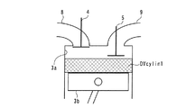
エンジン3は、4組の気筒3aおよびピストン3b(1組のみ図示)を有する直列4気筒ガソリンエンジンであり、図示しない車両に搭載されている。また、エンジン3は、気筒3aごとに設けられた吸気弁4(1つのみ図示)と、気筒3aごとに設けられた排気弁5(1つのみ図示)と、吸気弁4を開閉駆動する吸気動弁機構10と、排気弁5を開閉駆動する排気動弁機構20などを備えている。
The
この吸気動弁機構10は、吸気弁4を駆動する吸気カムシャフト11と、可変吸気カム位相機構12などで構成されている。この可変吸気カム位相機構12は、吸気カムシャフト11のクランクシャフト3cに対する相対的な位相(以下「吸気カム位相」という)CAINを無段階に(すなわち連続的に)進角側または遅角側に変更することで、吸気弁4のバルブタイミングを変更するものであり、吸気カムシャフト11の吸気スプロケット(図示せず)側の端部に設けられている。
The
この可変吸気カム位相機構12は、具体的には、本出願人が特開2007−100522号公報などで提案済みのものと同様に構成されているので、その詳細な説明は省略するが、吸気カム位相制御弁12aなどを備えている。この可変吸気カム位相機構12の場合、ECU2からの駆動信号によって吸気カム位相制御弁12aが制御されることにより、吸気カム位相CAINを、値0と所定の最進角値CAIN_adとの間で連続的に変化させる。それにより、吸気弁4のバルブタイミングが、図2に実線で示す基準タイミングと、図2に1点鎖線で示す最進角タイミングとの間で無段階に変更される。なお、この図2では、排気上死点が「排気TDC」と表記されており、この点は後述する各図においても同様である。
Specifically, the variable intake
この場合、所定の最進角値CAIN_adは、所定の正値に設定されている。したがって、吸気弁4のバルブタイミングは、吸気カム位相CAINが値0から増大するほど、基準タイミングに対してより進角側のタイミングに変更される。それにより、吸気弁4と排気弁5のバルブオーバーラップ期間がより長くなる。また、以下の説明では、吸気弁4のバルブタイミングを「吸気バルブタイミング」という。
In this case, the predetermined most advanced angle value CAIN_ad is set to a predetermined positive value. Accordingly, the valve timing of the
また、排気動弁機構20は、排気弁5を駆動する排気カムシャフト21と、可変排気カム位相機構22などで構成されている。この可変排気カム位相機構22は、排気カムシャフト21のクランクシャフト3cに対する相対的な位相(以下「排気カム位相」という)CAEXを無段階に(すなわち連続的に)進角側または遅角側に変更することで、排気弁5のバルブタイミングを変更するものであり、排気カムシャフト21の排気スプロケット(図示せず)側の端部に設けられている。
The
この可変排気カム位相機構22は、上述した可変吸気排気カム位相機構12と同様に構成されており、排気カム位相制御弁22aなどを備えている。この可変排気カム位相機構22の場合、ECU2からの駆動信号によって排気カム位相制御弁22aが制御されることにより、排気カム位相CAEXを、値0と所定の最遅角値CAEX_rtとの間で連続的に変化させる。それにより、排気弁5のバルブタイミングが、図2に実線で示す基準タイミングと、図2に破線で示す最遅角タイミングとの間で無段階に変更される。
The variable exhaust cam phase mechanism 22 is configured in the same manner as the variable intake exhaust
この場合、所定の最遅角値CAEX_rtは、所定の正値に設定されており、したがって、排気弁5のバルブタイミングは、排気カム位相CAEXが値0から増大するほど、基準タイミングに対してより遅角側のタイミングに変更される。それにより、バルブオーバーラップ期間がより長くなる。なお、以下の説明では、排気弁5のバルブタイミングを「排気バルブタイミング」という。
In this case, the predetermined maximum retardation value CAEX_rt is set to a predetermined positive value, and therefore, the valve timing of the
また、エンジン3には、点火プラグ6、燃料噴射弁7およびクランク角センサ30が設けられており、これらの点火プラグ6および燃料噴射弁7はいずれも、気筒3aごとに設けられている(いずれも1つのみ図示)。燃料噴射弁7は、各気筒3aの吸気ポート内に燃料を噴射するようにインテークマニホールドに取り付けられている。点火プラグ6および燃料噴射弁7はいずれも、ECU2に電気的に接続されており、ECU2によって、燃料噴射弁7による燃料の噴射量および噴射時期と、点火プラグ6による混合気の点火時期とが制御される。すなわち、燃料噴射制御と点火時期制御が実行される。
The
さらに、クランク角センサ30は、クランクシャフト3cの回転に伴い、パルス信号であるCRK信号をECU2に出力する。このCRK信号は、所定のクランク角(例えば1゜)ごとに1パルスが出力され、ECU2は、このCRK信号に基づき、エンジン3の回転数(以下「エンジン回転数」という)NEを算出する。
Further, the
一方、ECU2には、エアフローセンサ31、吸気圧センサ32、吸気温センサ33、排気圧センサ34、排気温センサ35、吸気カム角センサ36および排気カム角センサ37が電気的に接続されている。このエアフローセンサ31は、吸気通路8内を流れる新気の流量を検出して、それを表す検出信号をECU2に出力する。ECU2は、このエアフローセンサ31の検出信号に基づき、吸入空気量GAIRを算出する。
On the other hand, an
また、吸気圧センサ32は吸気通路8内の圧力(以下「吸気圧」という)Pinを、検出して、それを表す検出信号をECU2に出力する。この吸気圧Pinは、絶対圧として検出される。さらに、吸気温センサ33は、吸気通路8内の空気の温度(以下「吸気温」という)Tinを検出して、それを表す検出信号をECU2に出力する。この吸気温Tinは、絶対温度として検出される。
The
一方、排気圧センサ34は、排気通路9内の圧力(以下「排気圧」という)Pexを検出して、それを表す検出信号をECU2に出力する。この排気圧Pexは、絶対圧として検出される。また、排気温センサ35は、排気通路9内の排ガスの温度(以下「排気温」という)Texを検出して、それを表す検出信号をECU2に出力する。この排気温Texは、絶対温度として検出される。なお、本実施形態では、排気圧センサ34が排気圧取得手段に相当し、排気温センサ35が排気温取得手段に相当する。
On the other hand, the
また、吸気カム角センサ36は、吸気カムシャフト11の可変吸気カム位相機構12と反対側の端部に設けられており、吸気カムシャフト11の回転に伴い、パルス信号である吸気CAM信号を所定のカム角(例えば1゜)ごとにECU2に出力する。ECU2は、この吸気CAM信号および前述したCRK信号に基づき、吸気カム位相CAINを算出する。
The intake
さらに、排気カム角センサ37は、排気カムシャフト21の可変排気カム位相機構22と反対側の端部に設けられており、排気カムシャフト21の回転に伴い、パルス信号である排気CAM信号を所定のカム角(例えば1゜)ごとにECU2に出力する。ECU2は、この排気CAM信号および前述したCRK信号に基づき、排気カム位相CAEXを算出する。なお、本実施形態では、クランク角センサ30、吸気カム角センサ36、および排気カム角センサ37がバルブタイミング取得手段に相当し、吸気カム位相CAINが吸気弁4のバルブタイミングを、排気カム位相CAEXが排気弁5のバルブタイミングをそれぞれ表す値に相当する。
Further, the exhaust
一方、ECU2は、CPU、RAM、ROMおよびI/Oインターフェース(いずれも図示せず)などからなるマイクロコンピュータで構成されており、以上の各種のセンサ30〜37の検出信号などに基づいて、以下に述べるように、内部EGR量の算出処理を実行するとともに、点火プラグ6、燃料噴射弁7、吸気カム位相制御弁12aおよび排気カム位相制御弁22aの動作状態を制御する。
On the other hand, the
なお、本実施形態では、ECU2が、バルブタイミング取得手段、基準筒内ガス量算出手段、流出入ガス変化量算出手段、内部EGR量算出手段、基準筒内容積取得手段、流出ガス変化量算出手段、および流入ガス変化量算出手段に相当する。
In this embodiment, the
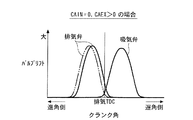
以下、本実施形態の内部EGR量算出装置1による内部EGR量の算出手法の原理および観点について説明する。まず、図3を参照しながら、CAIN=CAEX=0に設定されている場合、すなわち吸気バルブタイミングおよび排気バルブタイミングがいずれも前述した図2に実線で示す基準タイミングに設定されている場合の既燃ガスの流れについて説明する。
Hereinafter, the principle and viewpoint of the calculation method of the internal EGR amount by the internal EGR
なお、図3(a)において、ハッチングを施した矢印が気筒3a内から吸気通路8および排気通路9に流れ出る既燃ガスの流れを表しており、図3(b)において、網掛けを施した矢印が吸気通路8および排気通路9から気筒3a内に流れ込む既燃ガスの流れを表している。これらの点は、後述する図6,10においても同様である。
In FIG. 3 (a), the hatched arrows represent the flow of burned gas flowing out from the
図3(a)に示すように、ピストン3bが排気上死点に到達していない状態では、排気弁5が開弁状態にあり、排気圧Pexが気筒3a内の圧力よりも低い状態にあることで、気筒3a内の既燃ガスが排気通路9側に流れ出る。これに加えて、吸気弁4が開き始めたタイミング以降、吸気圧Pinが気筒3a内の圧力よりも低い状態にあることで、気筒3a内の既燃ガスが吸気通路8側にも流れ出る。この場合、排気弁5のリフトが吸気弁4のリフトよりも大きいことで、排気通路9側への既燃ガスの流出量が、吸気通路8側への流出量よりも多い状態となる。
As shown in FIG. 3A, when the
また、図3(b)に示すように、ピストン3bが排気上死点に達した以降は、吸気弁4および排気弁5の双方が開弁状態にあることで、既燃ガスが吸気通路8側および排気通路9側から気筒3a内に流れ込む。そして、排気弁5が閉弁した以降は、既燃ガスが吸気通路8側からのみ気筒3a内に流れ込むことになることで、吸気通路8側からの既燃ガスの流入量が、排気通路9側からの流入量よりも多い状態となる。
Further, as shown in FIG. 3B, after the
以上の動作原理により、本実施形態のエンジン3の場合、吸気バルブタイミングおよび排気バルブタイミングがいずれも基準タイミングに設定されているときには、図4に示すように、既燃ガスの気筒3a外への流出量と気筒3a内への流入量とが互いに同じ値になるとともに、内部EGR量GEGR1は、後述する基準内部EGR量GEGR1_0となる。なお、同図において、ハッチングを施した矢印の長さが既燃ガスの気筒3a内への流入量を表すとともに、網掛けを施した矢印の長さが気筒3a外への流出量を表している。これらの点は、後述する図7,11においても同様である。
Based on the above operating principle, in the case of the
一方、図5に示すように、CAIN=0で、CAEX>0に設定されている場合、すなわち、吸気バルブタイミングが基準タイミングに設定され、排気バルブタイミングが基準タイミングよりも遅角側に設定されている場合、既燃ガスの流れは図6に示すようになる。なお、図5において、実線で示す排気弁5のバルブリフト曲線がCAEX>0のときのものであり、2点鎖線のバルブリフト曲線は、参考のために示したCAEX=0のときのものである。
On the other hand, as shown in FIG. 5, when CAIN = 0 and CAEX> 0 is set, that is, the intake valve timing is set to the reference timing, and the exhaust valve timing is set to the retard side from the reference timing. If so, the flow of burned gas is as shown in FIG. In FIG. 5, the valve lift curve of the
まず、図6(a)に示すように、ピストン3bが排気上死点に到達していない状態では、前述した図3(a)の場合と同様に、排気弁5が開弁状態にあり、排気圧Pexが気筒3a内の圧力よりも低い状態にあることで、気筒3a内の既燃ガスが排気通路9側に流れ出る。これに加えて、吸気弁4が開き始めたタイミング以降、吸気圧Pinが気筒3a内の圧力よりも低い状態にあることで、気筒3a内の既燃ガスが吸気通路8側にも流れ出る。この場合、CAIN=0であるので、既燃ガスの流出量は、図3(a)の場合と同じになる。
First, as shown in FIG. 6A, in the state where the
また、図6(b)に示すように、ピストン3bが排気上死点に達した以降は、前述した図3(b)の場合と同様に、吸気弁4および排気弁5の双方が開弁状態にあることで、既燃ガスが吸気通路8側および排気通路9側から気筒3a内に流れ込む。そして、排気弁5が閉弁した以降は、既燃ガスが吸気通路8側からのみ気筒3a内に流れ込むことになる。この場合、CAEX>0であり、排気弁5の閉弁タイミングがCAEX=0のときよりも遅角側になるので、既燃ガスの流入量は、図3(b)の場合よりも多くなる。
Further, as shown in FIG. 6B, after the
以上のように、本実施形態のエンジン3では、CAIN=0で、CAEX>0に設定されている場合、CAIN=CAEX=0の場合と比べて、既燃ガスの気筒3a外への流出量は同じであるものの、既燃ガスの気筒3a内への流入量が多くなる。その結果、図7に示すように、内部EGR量GEGR1は、前述した基準内部EGR量GEGR1_0に増大量DGEGR1_EXを加えた値GEGR1_EXとなる。これは、排気バルブタイミングが基準タイミングよりも遅角側に設定されていることに起因して、図8に示すように、筒内容積が基準タイミングのときと比べて、増大量DVcylex1(図中の網掛けで示す領域の容積)分、増大したと見なせる状態にあることを意味する。
As described above, in the
また、図9に示すように、CAIN>0で、CAEX=0に設定されている場合、すなわち、吸気バルブタイミングが基準タイミングよりも進角側に設定され、排気バルブタイミングが基準タイミングに設定されている場合、既燃ガスの流れは図10に示すようになる。なお、図9において、実線で示す吸気弁4のバルブリフト曲線がCAIN>0のときのものであり、2点鎖線のバルブリフト曲線は、参考のために示したCAIN=0のときのものである。
Further, as shown in FIG. 9, when CAIN> 0 and CAEX = 0, that is, the intake valve timing is set to the advance side with respect to the reference timing, and the exhaust valve timing is set to the reference timing. If so, the flow of burned gas is as shown in FIG. In FIG. 9, the valve lift curve of the
まず、図10(a)に示すように、ピストン3bが排気上死点に到達していない状態では、前述した図3(a)の場合と同様に、排気弁5が開弁状態にあり、排気圧Pexが気筒3a内の圧力よりも低い状態にあることで、気筒3a内の既燃ガスが排気通路9側に流れ出る。これに加えて、吸気弁4が開き始めたタイミング以降、吸気圧Pinが気筒3a内の圧力よりも低い状態にあることで、気筒3a内の既燃ガスが吸気通路8側にも流れ出る。この場合、CAIN>0であり、吸気弁4の開弁タイミングがCAIN=0のときよりも進角側であるので、既燃ガスの流出量は、図3(a)の場合よりも多くなる。
First, as shown in FIG. 10 (a), in the state where the
また、図10(b)に示すように、ピストン3bが排気上死点に達した以降は、前述した図3(b)の場合と同様に、吸気弁4および排気弁5の双方が開弁状態にあることで、既燃ガスが吸気通路8側および排気通路9側から気筒3a内に流れ込む。そして、排気弁5が閉弁した以降は、既燃ガスが吸気通路8側からのみ気筒3a内に流れ込むことになる。この場合、CAEX=0であるので、既燃ガスの流入量は、図3(b)の場合と同じになる。
Further, as shown in FIG. 10 (b), after the
以上のように、本実施形態のエンジン3では、CAIN>0で、CAEX=0に設定されている場合、CAIN=CAEX=0の場合と比べて、既燃ガスの気筒3a内への流入量は同じであるものの、既燃ガスの気筒3a外への流出量が多くなる。その結果、図11に示すように、内部EGR量GEGR1は、前述した基準内部EGR量GEGR1_0から減少量DGEGR1_INを減算した値GEGR1_INとなる。これは、吸気バルブタイミングが基準タイミングよりも進角側に設定されていることに起因して、図12に示すように、筒内容積が基準タイミングのときと比べて、減少量DVcylin1(図中の網掛けで示す領域の容積)分、減少したと見なせる状態にあることを意味する。
As described above, in the
以上の原理および観点に基づき、この内部EGR量算出装置1では、図13に示すように、内部EGR量の算出処理が実行される。なお、この算出処理は、具体的には、ECU2によって所定周期で実行される。
Based on the above principle and viewpoint, the internal EGR
同図に示すように、まず、ステップ1(図では「S1」と略す。以下同じ)で、ROM内に記憶されている2つの基準筒内容積Vcylin_0,Vcylex_0の値を読み込む。これらの基準筒内容積Vcylin_0,Vcylex_0は、CAIN=CAEX=0のとき、すなわち吸気バルブタイミングおよび排気バルブタイミングがいずれも基準タイミングにあるときの筒内容積であり、互いに同じ値に設定されている。 As shown in the figure, first, in step 1 (abbreviated as “S1” in the figure, the same applies hereinafter), the values of the two reference in-cylinder volumes Vcylin_0 and Vcylex_0 stored in the ROM are read. These reference in-cylinder volumes Vcylin_0 and Vcylex_0 are in-cylinder volumes when CAIN = CAEX = 0, that is, when both the intake valve timing and the exhaust valve timing are at the reference timing, and are set to the same value. .
次に、ステップ2に進み、下式(1)により、基準内部EGR量GEGR1_0(基準筒内ガス量)を算出する。
![]()
![]()
この式(1)は気体の状態方程式であり、式(1)のReは気体定数である。 This equation (1) is an equation of state of gas, and Re in equation (1) is a gas constant.
ステップ2に続くステップ3で、吸気カム位相CAINに応じて、図14に示すマップを検索することにより、筒内容積の吸気マップ値Vcylin_mapを算出する。この吸気マップ値Vcylin_mapは、吸気バルブタイミングが基準タイミングよりも進角側に設定されることに起因する、既燃ガスの気筒3a外への流出量の増大分を、基準筒内容積Vcylin_0に上乗せした値であり、同図に示すように、吸気カム位相CAINが大きいほど、より大きい値に設定されている。これは、吸気カム位相CAINが大きいほど、吸気バルブタイミングが基準タイミングに対してより進角側に設定されることで、既燃ガスの流出量がより増大することによる。
In
次いで、ステップ4に進み、下式(2)により、減少量DVcylin1を算出する。この減少量DVcylin1は、前述したように、吸気バルブタイミングが基準タイミングよりも進角側にあることに起因する、筒内容積の減少量と見なせる値である。
![]()
![]()
次に、ステップ5で、排気カム位相CAEXに応じて、図15に示すマップを検索することにより、筒内容積の排気マップ値Vcylex_mapを算出する。この排気マップ値Vcylex_mapは、排気バルブタイミングが基準タイミングよりも遅角側に設定されることに起因する、既燃ガスの気筒3a内への流入量の増大分を、基準筒内容積Vcylex_0に上乗せした値であり、同図に示すように、排気カム位相CAEXが大きいほど、より大きい値に設定されている。これは、排気カム位相CAEXが大きいほど、排気バルブタイミングが基準タイミングに対してより遅角側に設定されることで、既燃ガスの気筒3a内への流入量がより増大することによる。
Next, in
次いで、ステップ6に進み、下式(3)により、増大量DVcylex1を算出する。この増大量DVcylex1は、前述したように、排気バルブタイミングが基準タイミングよりも遅角側にあることに起因する、筒内容積の増大量と見なせる値である。
![]()
![]()
ステップ6に続くステップ7で、下式(4)により、流出ガス増大量DGEGR1_IN(流出ガス変化量)を算出する。この式(4)は気体の状態方程式に基づくものであり、この流出ガス増大量DGEGR1_INは、吸気バルブタイミングが基準タイミングよりも進角側にあるときの、既燃ガスの気筒3a外への流出量の増大分に相当する。
![]()
![]()
次いで、ステップ8に進み、下式(5)により、流入ガス増大量DGEGR1_EX(流入ガス変化量)を算出する。この式(5)は気体の状態方程式に基づくものであり、この流入ガス増大量DGEGR1_EXは、排気バルブタイミングが基準タイミングよりも遅角側にあるときの、既燃ガスの気筒3a内への流入量の増大分に相当する。
![]()
![]()
次に、ステップ9で、下式(6)により、内部EGR増減量DGEGR1(流出入ガス変化量)を算出する。
![]()
![]()
そして、最終的に、ステップ10で、下式(7)により、内部EGR量GEGR1を算出した後、本処理を終了する。
![]()
![]()
次に、図16および図17を参照しながら、本実施形態の内部EGR量算出装置1による内部EGR量GEGR1の算出結果の精度について説明する。両図において、横軸のオーバーラップ角度OVLは、吸気カム位相CAINと排気カム位相CAEXの和として算出される値であり、値OVLmaxは、OVLmax=CAIN_ad+CAEX_rtとなる、オーバーラップ角度OVLの最大値を示している。この場合、吸気カム位相CAINおよび排気カム位相CAEXが前述したように設定されている関係上、オーバーラップ角度OVLは、バルブオーバーラップ期間が長いほど、より大きい値として算出される。
Next, the accuracy of the calculation result of the internal EGR amount GEGR1 by the internal EGR
また、図16は、本実施形態の内部EGR量算出装置1による内部EGR量GEGR1の算出誤差とオーバーラップ角度OVLとの関係を表しており、この算出誤差は、内部EGR量GEGR1の算出結果と実際値との偏差を百分率で表したものである。また、図17は、比較のために、内部EGR増減量DGEGR1=0とし、内部EGR量GEGR1=GEGR1_0としたときの、内部EGR量GEGR1の算出誤差とオーバーラップ角度OVLとの関係を表している。
FIG. 16 shows the relationship between the calculation error of the internal EGR amount GEGR1 and the overlap angle OVL by the internal EGR
まず、図16に示すように、基準内部EGR量GEGR1_0を内部EGR増減量DGEGR1で補正することによって、内部EGR量GEGR1を算出した場合、オーバーラップ角度OVLの大小にかかわらず、算出誤差が±N(Nは整数)%の範囲内に収まっていることが判る。これに対して、図17に示すように、内部EGR増減量DGEGR1=0とし、内部EGR量GEGR1を基準内部EGR量GEGR1_0に等しい値として算出した場合には、算出誤差の絶対値が値Nを超えており、算出精度が低下していることが判る。すなわち、本実施形態のように、内部EGR量GEGR1を算出する際、基準内部EGR量GEGR1_0を内部EGR増減量DGEGR1で補正することによって、内部EGR量GEGR1の算出精度が向上することが判る。 First, as shown in FIG. 16, when the internal EGR amount GEGR1 is calculated by correcting the reference internal EGR amount GEGR1_0 with the internal EGR increase / decrease amount DGEGR1, the calculation error is ± N regardless of the overlap angle OVL. It can be seen that (N is an integer)%. In contrast, as shown in FIG. 17, when the internal EGR increase / decrease amount DGEGR1 = 0 and the internal EGR amount GEGR1 is calculated as a value equal to the reference internal EGR amount GEGR1_0, the absolute value of the calculation error is the value N. It can be seen that the calculation accuracy is reduced. That is, when calculating the internal EGR amount GEGR1 as in the present embodiment, it is understood that the calculation accuracy of the internal EGR amount GEGR1 is improved by correcting the reference internal EGR amount GEGR1_0 with the internal EGR increase / decrease amount DGEGR1.
以上のように、本実施形態の内部EGR量算出装置1によれば、基準内部EGR量GEGR1_0が、基準筒内容積Vcylin_0、排気温Texおよび排気圧Pexに基づき、気体の状態方程式を用いることによって算出される。この場合、吸気弁4が開き始めるタイミングでは、排気弁5が開弁状態にあることで、筒内ガスの圧力および温度はそれぞれ、排気圧Pexおよび排気温Texにほぼ等しい状態になる。したがって、そのような排気圧Pexおよび排気温Texを用いて、基準内部EGR量GEGR1_0を算出することにより、基準内部EGR量GEGR1_0を、吸気バルブタイミングおよび排気バルブタイミングがいずれも基準タイミングにあるときの内部EGR量として精度よく算出することができる。
As described above, according to the internal EGR
また、流入ガス増大量DGEGR1_EXから流出ガス増大量DGEGR1_INを減算することにより、内部EGR増減量DGEGR1が算出され、基準内部EGR量GEGR1_0に内部EGR増減量DGEGR1を加算することにより、内部EGR量GEGR1が算出される。この場合、流出ガス増大量DGEGR1_INは、吸気バルブタイミングが基準タイミングよりも進角側にあるときの、既燃ガスの気筒3a外への流出量の増大分に相当し、流入ガス増大量DGEGR1_EXは、排気バルブタイミングが基準タイミングよりも遅角側にあるときの、既燃ガスの気筒3a内への流入量の増大分に相当するので、内部EGR増減量DGEGR1は、既燃ガスの気筒3a内外への流出入量の、吸気バルブタイミングおよび排気バルブタイミングがいずれも基準タイミングにあるときの値に対する変化量として算出されることになる。したがって、そのような内部EGR増減量DGEGR1を基準内部EGR量GEGR1_0に加算することによって、内部EGR量GEGR1が算出されるので、吸気バルブタイミングおよび/または排気バルブタイミングの変更に伴う気筒3a内外に流出入する既燃ガス量の変化を反映させながら、内部EGR量GEGR1を適切にかつ精度よく算出することができる。それにより、内部EGR量G
EGR1の算出精度を向上させることができる。
Further, the internal EGR increase / decrease amount DGEGR1 is calculated by subtracting the outflow gas increase amount DGEGR1_IN from the inflow gas increase amount DGEGR1_EX, and the internal EGR amount GEGR1 is calculated by adding the internal EGR increase / decrease amount DGEGR1 to the reference internal EGR amount GEGR1_0. Calculated. In this case, the outflow gas increase amount DGEGR1_IN corresponds to an increase in the outflow amount of burnt gas to the outside of the
The calculation accuracy of EGR1 can be improved.
さらに、前述したように、基準内部EGR量GEGR1_0、流入ガス増大量DGEGR1_EX、流出ガス増大量DGEGR1_IN、内部EGR増減量DGEGR1および内部EGR量GEGR1を1回の算出処理で算出することができるので、積分演算処理を必要とする特許文献1の算出手法と比べて、内部EGR量GEGR1を容易に算出することができ、内部EGR量GEGR1を算出する際の演算負荷を低減することができる。それにより、商品性を向上させることができる。
Further, as described above, the reference internal EGR amount GEGR1_0, the inflow gas increase amount DGEGR1_EX, the outflow gas increase amount DGEGR1_IN, the internal EGR increase / decrease amount DGEGR1 and the internal EGR amount GEGR1 can be calculated in one calculation process. Compared with the calculation method of
なお、実施形態は、吸気弁4および排気弁5の少なくとも一方のバルブタイミングが変更される内燃機関として、可変吸気カム位相機構12および可変排気カム位相機構22を備えた内燃機関3を用いた例であるが、本発明の内燃機関はこれに限らず、吸気弁および/または排気弁のバルブタイミングを変更できる内燃機関であればよい。
In the embodiment, the
例えば、可変吸気カム位相機構12のみを備えた内燃機関に対して、本発明の内部EGR量算出装置を適用してもよい。その場合には、前述した図13の算出処理において、ステップ5,6,8を省略し、ステップ9の内部EGR増減量DGEGR1の算出式(6)において、DGEGR1_EX=0とすればよい。
For example, the internal EGR amount calculation device of the present invention may be applied to an internal combustion engine that includes only the variable intake
また、可変排気カム位相機構22のみを備えた内燃機関に対して、本発明の内部EGR量算出装置を適用してもよい。その場合には、前述した図13の算出処理において、ステップ3,4,7を省略し、ステップ9の内部EGR増減量DGEGR1の算出式(6)において、DGEGR1_IN=0とすればよい。
Further, the internal EGR amount calculation device of the present invention may be applied to an internal combustion engine provided with only the variable exhaust cam phase mechanism 22. In that case, steps 3, 4 and 7 may be omitted in the calculation process of FIG. 13 described above, and DGEGR1_IN = 0 in the calculation formula (6) of the internal EGR increase / decrease amount DGEGR1 in
さらに、可変吸気カム位相機構12および可変排気カム位相機構22以外の機構によって、吸気弁4および/または排気弁5のバルブタイミングが変更される内燃機関を用いてもよい。例えば、バルブタイミングを変更する機構として、電気モータとギヤ機構を組み合わせたタイプの可変カム位相機構や、ソレノイドによって弁体が駆動される電磁動弁機構、3次元カムによってバルブタイミングを機械的に変更するバルブタイミング変更機構や、吸気弁4および/または排気弁5のリフトを変更することによって、吸気弁4および/または排気弁5のバルブタイミングを変更するバルブタイミング変更機構を用いてもよい。
Furthermore, an internal combustion engine in which the valve timing of the
さらに、本発明の内部EGR量算出装置を、可変吸気カム位相機構12および可変排気カム位相機構22に加えて、吸気弁4および/または排気弁5のバルブリフトを変更する可変リフト機構をさらに備えた内燃機関に対して適用してもよい。その場合には、前述した図14,15のマップに代えて、N(Nは2以上の整数)個のバルブリフトの値に対応して、吸気マップ値Vcylin_mapと吸気カム位相CAINの関係、および排気マップ値Vcylex_mapと排気カム位相CAEXの関係が設定されたN個のマップを用いて、2つの値Vcylin_map,Vcylex_mapを算出するように構成すればよい。また、前述した図14,15のマップに代えて、2つの値Vcylin_map,Vcylex_mapと、2つの吸気カム位相CAIN,CAEXおよびバルブリフトとの関係を定義した2つのマップを用いて、2つの値Vcylin_map,Vcylex_mapを算出するように構成してもよい。
In addition to the variable intake
また、実施形態は、バルブタイミング取得手段として、ECU2、クランク角センサ30、吸気カム角センサ36、排気カム角センサ37を用いた例であるが、本発明のバルブタイミング取得手段はこれらに限らず、バルブタイミングを取得できるものであればよい。例えば、ECU2および上記以外のセンサなどを用いて、バルブタイミングを検出するように構成してもよい。
The embodiment is an example in which the
さらに、実施形態は、排気圧取得手段として、排気圧センサ34を用いた例であるが、本発明の排気圧取得手段はこれに限らず、排気圧を取得できるものであればよい。例えば、モデル式を用いた推定演算手法により、排気圧の推定値を算出するように構成してもよい。
Further, the embodiment is an example in which the
一方、実施形態は、排気温取得手段として、排気温センサ35を用いた例であるが、本発明の排気温取得手段はこれに限らず、排気温を取得できるものであればよい。例えば、モデル式を用いた推定演算手法により、排気温の推定値を算出するように構成してもよい。
On the other hand, the embodiment is an example in which the
また、実施形態は、本発明の内部EGR量算出装置1を車両用の内燃機関3に適用した例であるが、本発明の内部EGR量算出装置は、これに限らず、船舶用の内燃機関や、他の産業機器用の内燃機関にも適用可能である。
The embodiment is an example in which the internal EGR
1 内部EGR量算出装置
2 ECU(バルブタイミング取得手段、基準筒内ガス量算出手段、流出入ガス変化 量算出手段、内部EGR量算出手段、基準筒内容積取得手段、流出ガス変化量算 出手段、流入ガス変化量算出手段)
3 内燃機関
3a 気筒
4 吸気弁
5 排気弁
9 排気通路
30 クランク角センサ(バルブタイミング取得手段)
34 排気圧センサ(排気圧取得手段)
35 排気温センサ(排気温取得手段)
36 吸気カム角センサ(バルブタイミング取得手段)
37 排気カム角センサ(バルブタイミング取得手段)
GEGR1_0 基準内部EGR量(基準筒内ガス量)
DGEGR1 内部EGR増減量(流出入ガス変化量)
GEGR1 内部EGR量
Tex 排気温
Pex 排気圧
Vcylin_0 基準筒内容積
CAIN 吸気カム位相(吸気弁のバルブタイミングを表す値)
DGEGR1_IN 流出ガス増大量(流出ガス変化量)
CAEX 排気カム位相(排気弁のバルブタイミングを表す値)
DGEGR1_EX 流入ガス増大量(流入ガス変化量)
1 Internal EGR
DESCRIPTION OF
34 Exhaust pressure sensor (exhaust pressure acquisition means)
35 Exhaust temperature sensor (exhaust temperature acquisition means)
36 Intake cam angle sensor (valve timing acquisition means)
37 Exhaust cam angle sensor (valve timing acquisition means)
GEGR1_0 Reference internal EGR amount (reference cylinder gas amount)
DGEGR1 Internal EGR increase / decrease amount (outflow / inflow gas change amount)
GEGR1 Internal EGR amount
Tex exhaust temperature
Pex Exhaust pressure Vcylin_0 Reference cylinder volume
CAIN intake cam phase (value indicating valve timing of intake valve)
DGEGR1_IN Outflow gas increase (outflow gas change amount)
CAEX Exhaust cam phase (value indicating valve timing of exhaust valve)
DGEGR1_EX Inflow gas increase amount (inflow gas change amount)
Claims (7)
前記バルブタイミングを取得するバルブタイミング取得手段と、
前記バルブタイミングが所定の基準タイミングにあるときに前記気筒内に残留する既燃ガス量である基準筒内ガス量を算出する基準筒内ガス量算出手段と、
前記バルブタイミングに応じて、前記吸気弁および前記排気弁の開弁期間中において前記気筒内に流出入する既燃ガスの、前記バルブタイミングが前記所定の基準タイミングにあるときの流出入量に対する変化量を流出入ガス変化量として算出する流出入ガス変化量算出手段と、
前記基準筒内ガス量に前記流出入ガス変化量を加算することにより、前記内部EGR量を算出する内部EGR量算出手段と、
を備えることを特徴とする内燃機関の内部EGR量算出装置。 By changing the valve timing of at least one of the intake valve and the exhaust valve, the internal EGR amount that is the amount of burnt gas remaining in the cylinder is changed , and one combustion cycle is performed regardless of the change state of the valve timing. An internal EGR amount calculation device for an internal combustion engine configured to generate valve overlap therein ,
Valve timing acquisition means for acquiring the valve timing;
Reference in-cylinder gas amount calculating means for calculating a reference in-cylinder gas amount that is an amount of burnt gas remaining in the cylinder when the valve timing is at a predetermined reference timing;
Change of burned gas flowing into and out of the cylinder during the opening period of the intake valve and the exhaust valve according to the valve timing with respect to the inflow / outflow amount when the valve timing is at the predetermined reference timing An inflow / outflow gas change amount calculating means for calculating the amount as an inflow / outflow gas change amount;
By adding the inflow and outflow gas change amount to the reference in-cylinder gas amount, and the internal EGR quantity calculating means for calculating the internal EGR amount,
An internal EGR amount calculation apparatus for an internal combustion engine, comprising:
前記バルブタイミングを取得するバルブタイミング取得手段と、
前記バルブタイミングが所定の基準タイミングにあるときに前記気筒内に残留する既燃ガス量である基準筒内ガス量を算出する基準筒内ガス量算出手段と、
前記バルブタイミングに応じて、前記吸気弁および前記排気弁の開弁期間中において前記気筒内に流出入する既燃ガスの、前記バルブタイミングが前記所定の基準タイミングにあるときの流出入量に対する変化量を流出入ガス変化量として算出する流出入ガス変化量算出手段と、
前記基準筒内ガス量および前記流出入ガス変化量に基づき、前記内部EGR量を算出する内部EGR量算出手段と、
を備え、
前記吸気弁のバルブタイミングが変更可能に構成されており、
前記バルブタイミング取得手段は、前記吸気弁のバルブタイミングを取得し、
前記吸気弁のバルブタイミングに基づき、前記気筒内から流出する既燃ガス量の、当該吸気弁のバルブタイミングが前記所定の基準タイミングにあるときの値に対する変化分を流出ガス変化量として算出する流出ガス変化量算出手段をさらに備え、
前記流出入ガス変化量算出手段は、前記流出ガス変化量に基づき、前記流出入ガス変化量を算出することを特徴とする内燃機関の内部EGR量算出装置。 An internal EGR amount calculation device for an internal combustion engine in which an internal EGR amount that is an amount of burnt gas remaining in a cylinder is changed by changing a valve timing of at least one of an intake valve and an exhaust valve,
Valve timing acquisition means for acquiring the valve timing;
Reference in-cylinder gas amount calculating means for calculating a reference in-cylinder gas amount that is an amount of burnt gas remaining in the cylinder when the valve timing is at a predetermined reference timing;
Change of burned gas flowing into and out of the cylinder during the opening period of the intake valve and the exhaust valve according to the valve timing with respect to the inflow / outflow amount when the valve timing is at the predetermined reference timing An inflow / outflow gas change amount calculating means for calculating the amount as an inflow / outflow gas change amount;
An internal EGR amount calculating means for calculating the internal EGR amount based on the reference in-cylinder gas amount and the inflow / outflow gas change amount;
With
The valve timing of the intake valve is configured to be changeable,
The valve timing acquisition means acquires the valve timing of the intake valve,
Based on the valve timing of the intake valve, the amount of burned gas flowing out of the cylinder is calculated as the amount of change in the amount of outflow gas with respect to the value when the valve timing of the intake valve is at the predetermined reference timing A gas change amount calculating means;
The internal EGR amount calculation device for an internal combustion engine, wherein the outflow / inflow gas change amount calculation means calculates the outflow / inflow gas change amount based on the outflow gas change amount .
前記バルブタイミングを取得するバルブタイミング取得手段と、
前記バルブタイミングが所定の基準タイミングにあるときに前記気筒内に残留する既燃ガス量である基準筒内ガス量を算出する基準筒内ガス量算出手段と、
前記バルブタイミングに応じて、前記吸気弁および前記排気弁の開弁期間中において前記気筒内に流出入する既燃ガスの、前記バルブタイミングが前記所定の基準タイミングにあるときの流出入量に対する変化量を流出入ガス変化量として算出する流出入ガス変化量算出手段と、
前記基準筒内ガス量および前記流出入ガス変化量に基づき、前記内部EGR量を算出する内部EGR量算出手段と、
を備え、
前記吸気弁および前記排気弁の双方のバルブタイミングが変更可能に構成されており、
前記バルブタイミング取得手段は、前記吸気弁および前記排気弁の双方のバルブタイミングを取得し、
前記吸気弁のバルブタイミングに基づき、前記気筒内から流出する既燃ガス量の、当該吸気弁のバルブタイミングが前記所定の基準タイミングにあるときの値に対する変化分を流出ガス変化量として算出する流出ガス変化量算出手段と、
前記排気弁のバルブタイミングに基づき、前記気筒内に流入する既燃ガス量の、当該排気弁のバルブタイミングが前記所定の基準タイミングにあるときの値に対する変化分を流入ガス変化量として算出する流入ガス変化量算出手段と、をさらに備え、
前記流出入ガス変化量算出手段は、前記流出ガス変化量および前記流入ガス変化量に基づき、前記流出入ガス変化量を算出することを特徴とする内燃機関の内部EGR量算出装置。 An internal EGR amount calculation device for an internal combustion engine in which an internal EGR amount that is an amount of burnt gas remaining in a cylinder is changed by changing a valve timing of at least one of an intake valve and an exhaust valve,
Valve timing acquisition means for acquiring the valve timing;
Reference in-cylinder gas amount calculating means for calculating a reference in-cylinder gas amount that is an amount of burnt gas remaining in the cylinder when the valve timing is at a predetermined reference timing;
Change of burned gas flowing into and out of the cylinder during the opening period of the intake valve and the exhaust valve according to the valve timing with respect to the inflow / outflow amount when the valve timing is at the predetermined reference timing An inflow / outflow gas change amount calculating means for calculating the amount as an inflow / outflow gas change amount;
An internal EGR amount calculating means for calculating the internal EGR amount based on the reference in-cylinder gas amount and the inflow / outflow gas change amount;
With
The valve timing of both the intake valve and the exhaust valve is configured to be changeable,
The valve timing acquisition means acquires valve timings of both the intake valve and the exhaust valve,
Based on the valve timing of the intake valve, the amount of burned gas flowing out of the cylinder is calculated as the amount of change in the amount of outflow gas with respect to the value when the valve timing of the intake valve is at the predetermined reference timing A gas change amount calculating means;
Based on the valve timing of the exhaust valve, an inflow for calculating a change amount of the burned gas amount flowing into the cylinder with respect to a value when the valve timing of the exhaust valve is at the predetermined reference timing as an inflow gas change amount A gas change amount calculating means,
The internal EGR amount calculation device for an internal combustion engine , wherein the outflow / inflow gas change amount calculation means calculates the outflow / inflow gas change amount based on the outflow gas change amount and the inflow gas change amount .
前記内燃機関の前記排気通路内の排ガスの圧力である排気圧を取得する排気圧取得手段と、Exhaust pressure acquisition means for acquiring an exhaust pressure which is a pressure of exhaust gas in the exhaust passage of the internal combustion engine;
前記バルブタイミングが前記所定の基準タイミングにあるときの前記気筒の容積である基準筒内容積を取得する基準筒内容積取得手段と、をさらに備え、A reference in-cylinder volume acquisition means for acquiring a reference in-cylinder volume that is a volume of the cylinder when the valve timing is at the predetermined reference timing;
前記基準筒内ガス量算出手段は、前記排気温、前記排気圧および前記基準筒内容積に基づき、気体の状態方程式を用いることによって、前記基準筒内ガス量を算出することを特徴とする請求項1ないし3のいずれかに記載の内燃機関の内部EGR量算出装置。The reference in-cylinder gas amount calculating means calculates the reference in-cylinder gas amount by using a gas equation of state based on the exhaust temperature, the exhaust pressure, and the reference in-cylinder volume. Item 4. The internal EGR amount calculation device for an internal combustion engine according to any one of Items 1 to 3.
前記バルブタイミング取得手段は、前記吸気弁のバルブタイミングを取得し、The valve timing acquisition means acquires the valve timing of the intake valve,
前記吸気弁のバルブタイミングに基づき、前記気筒内から流出する既燃ガス量の、当該吸気弁のバルブタイミングが前記所定の基準タイミングにあるときの値に対する変化分を流出ガス変化量として算出する流出ガス変化量算出手段を、をさらに備え、Based on the valve timing of the intake valve, the amount of burned gas flowing out of the cylinder is calculated as the amount of change in the amount of outflow gas with respect to the value when the valve timing of the intake valve is at the predetermined reference timing A gas change amount calculating means,
前記流出入ガス変化量算出手段は、前記流出ガス変化量に基づき、前記流出入ガス変化量を算出することを特徴とする請求項1に記載の内燃機関の内部EGR量算出装置。2. The internal EGR amount calculation device for an internal combustion engine according to claim 1, wherein the outflow / inflow gas change amount calculation means calculates the outflow / inflow gas change amount based on the outflow gas change amount.
前記バルブタイミング取得手段は、前記排気弁のバルブタイミングを取得し、The valve timing acquisition means acquires the valve timing of the exhaust valve,
前記排気弁のバルブタイミングに基づき、前記気筒内に流入する既燃ガス量の、当該排気弁のバルブタイミングが前記所定の基準タイミングにあるときの値に対する変化分を流入ガス変化量として算出する流入ガス変化量算出手段をさらに備え、Based on the valve timing of the exhaust valve, an inflow for calculating a change amount of the burned gas amount flowing into the cylinder with respect to a value when the valve timing of the exhaust valve is at the predetermined reference timing as an inflow gas change amount A gas change amount calculating means;
前記流出入ガス変化量算出手段は、前記流入ガス変化量に基づき、前記流出入ガス変化量を算出することを特徴とする請求項1に記載の内燃機関の内部EGR量算出装置。2. The internal EGR amount calculation device for an internal combustion engine according to claim 1, wherein the outflow / inflow gas change amount calculation means calculates the outflow / inflow gas change amount based on the inflow gas change amount.
前記バルブタイミング取得手段は、前記吸気弁および前記排気弁の双方のバルブタイミングを取得し、
前記吸気弁のバルブタイミングに基づき、前記気筒内から流出する既燃ガス量の、当該吸気弁のバルブタイミングが前記所定の基準タイミングにあるときの値に対する変化分を流出ガス変化量として算出する流出ガス変化量算出手段と、
前記排気弁のバルブタイミングに基づき、前記気筒内に流入する既燃ガス量の、当該排気弁のバルブタイミングが前記所定の基準タイミングにあるときの値に対する変化分を流入ガス変化量として算出する流入ガス変化量算出手段と、をさらに備え、
前記流出入ガス変化量算出手段は、前記流出ガス変化量および前記流入ガス変化量に基づき、前記流出入ガス変化量を算出することを特徴とする請求項1に記載の内燃機関の内部EGR量算出装置。 The valve timing of both the intake valve and the exhaust valve is configured to be changeable ,
The valve timing acquisition means acquires valve timings of both the intake valve and the exhaust valve,
Based on the valve timing of the intake valve, the amount of burned gas flowing out of the cylinder is calculated as the amount of change in the amount of outflow gas with respect to the value when the valve timing of the intake valve is at the predetermined reference timing A gas change amount calculating means;
Based on the valve timing of the exhaust valve, an inflow for calculating a change amount of the burned gas amount flowing into the cylinder with respect to a value when the valve timing of the exhaust valve is at the predetermined reference timing as an inflow gas change amount A gas change amount calculating means,
2. The internal EGR amount of the internal combustion engine according to claim 1, wherein the outflow / inflow gas change amount calculating means calculates the outflow / inflow gas change amount based on the outflow gas change amount and the inflow gas change amount. Calculation device.
Priority Applications (3)
| Application Number | Priority Date | Filing Date | Title |
|---|---|---|---|
| JP2012151237A JP5844225B2 (en) | 2012-07-05 | 2012-07-05 | Internal EGR amount calculation device for internal combustion engine |
| US13/928,929 US10677201B2 (en) | 2012-07-05 | 2013-06-27 | Internal EGR amount calculation device for internal combustion engine |
| DE102013212993.9A DE102013212993A1 (en) | 2012-07-05 | 2013-07-03 | Internal EGR quantity calculation device for internal combustion engine |
Applications Claiming Priority (1)
| Application Number | Priority Date | Filing Date | Title |
|---|---|---|---|
| JP2012151237A JP5844225B2 (en) | 2012-07-05 | 2012-07-05 | Internal EGR amount calculation device for internal combustion engine |
Publications (3)
| Publication Number | Publication Date |
|---|---|
| JP2014013024A JP2014013024A (en) | 2014-01-23 |
| JP2014013024A5 JP2014013024A5 (en) | 2015-01-29 |
| JP5844225B2 true JP5844225B2 (en) | 2016-01-13 |
Family
ID=49780833
Family Applications (1)
| Application Number | Title | Priority Date | Filing Date |
|---|---|---|---|
| JP2012151237A Expired - Fee Related JP5844225B2 (en) | 2012-07-05 | 2012-07-05 | Internal EGR amount calculation device for internal combustion engine |
Country Status (3)
| Country | Link |
|---|---|
| US (1) | US10677201B2 (en) |
| JP (1) | JP5844225B2 (en) |
| DE (1) | DE102013212993A1 (en) |
Families Citing this family (6)
| Publication number | Priority date | Publication date | Assignee | Title |
|---|---|---|---|---|
| JP5648040B2 (en) * | 2012-12-18 | 2015-01-07 | 本田技研工業株式会社 | Internal EGR amount calculation device for internal combustion engine |
| JP6174264B2 (en) * | 2014-08-01 | 2017-08-02 | 本田技研工業株式会社 | Control device and control method for internal combustion engine |
| US10425548B2 (en) * | 2017-01-06 | 2019-09-24 | Ricoh Company, Ltd. | System for modifying a set of application services on multi-function print devices |
| JP6869475B2 (en) * | 2017-05-12 | 2021-05-12 | アイシン精機株式会社 | Internal combustion engine control device |
| KR20200074519A (en) * | 2018-12-17 | 2020-06-25 | 현대자동차주식회사 | Air-fuel ratio control method in vehicle comprising continuosly variable vale duration appratus and active purge system |
| DE102019213132A1 (en) * | 2019-08-30 | 2021-03-04 | Ford Global Technologies, Llc | Method for operating a hydrogen combustion engine with internal exhaust gas recirculation, engine system, motor vehicle and computer program product |
Family Cites Families (8)
| Publication number | Priority date | Publication date | Assignee | Title |
|---|---|---|---|---|
| US6827051B2 (en) | 1999-12-03 | 2004-12-07 | Nissan Motor Co., Ltd. | Internal EGR quantity estimation, cylinder intake air quantity calculation, valve timing control, and ignition timing control |
| JP3959957B2 (en) * | 1999-12-03 | 2007-08-15 | 日産自動車株式会社 | Engine internal EGR amount estimation method, variable valve control method using the internal EGR amount estimation value, cylinder intake air amount calculation method, and ignition timing control method |
| JP4162437B2 (en) * | 2002-07-15 | 2008-10-08 | 株式会社日立製作所 | Residual gas amount estimation method for internal combustion engine and control device for variable valve mechanism using the same |
| JP4154972B2 (en) * | 2002-09-19 | 2008-09-24 | 日産自動車株式会社 | Internal EGR amount estimation device for internal combustion engine |
| US6840235B2 (en) * | 2002-09-19 | 2005-01-11 | Nissan Motor Co., Ltd. | Internal exhaust gas recirculation amount estimation system of internal combustion engines |
| JP4277535B2 (en) | 2003-02-19 | 2009-06-10 | トヨタ自動車株式会社 | Internal EGR amount estimation device for internal combustion engine |
| JP4463179B2 (en) | 2005-09-30 | 2010-05-12 | 本田技研工業株式会社 | EGR control device for internal combustion engine |
| US7275516B1 (en) * | 2006-03-20 | 2007-10-02 | Ford Global Technologies, Llc | System and method for boosted direct injection engine |
-
2012
- 2012-07-05 JP JP2012151237A patent/JP5844225B2/en not_active Expired - Fee Related
-
2013
- 2013-06-27 US US13/928,929 patent/US10677201B2/en active Active
- 2013-07-03 DE DE102013212993.9A patent/DE102013212993A1/en not_active Withdrawn
Also Published As
| Publication number | Publication date |
|---|---|
| US20140007854A1 (en) | 2014-01-09 |
| JP2014013024A (en) | 2014-01-23 |
| DE102013212993A1 (en) | 2014-01-09 |
| US10677201B2 (en) | 2020-06-09 |
Similar Documents
| Publication | Publication Date | Title |
|---|---|---|
| JP6174264B2 (en) | Control device and control method for internal combustion engine | |
| JP5844225B2 (en) | Internal EGR amount calculation device for internal combustion engine | |
| JP5944249B2 (en) | Internal EGR amount calculation device for internal combustion engine | |
| JP5905066B1 (en) | Control device and control method for internal combustion engine | |
| JP5844227B2 (en) | Scavenging gas amount calculation device and internal EGR amount calculation device for internal combustion engine | |
| JP6606525B2 (en) | Control device for internal combustion engine | |
| US20110172898A1 (en) | Internal combustion engine system control device | |
| JP5648040B2 (en) | Internal EGR amount calculation device for internal combustion engine | |
| JP5331613B2 (en) | In-cylinder gas amount estimation device for internal combustion engine | |
| JP2007332944A (en) | Fuel injection control device of internal combustion engine | |
| JP2006307668A (en) | Egr flow rate estimating device of engine | |
| US10113490B2 (en) | Control apparatus for internal combustion engine | |
| JP2014005819A (en) | Internal egr amount calculating device for internal combustion engine | |
| JP2004218638A (en) | Operating method for internal-combustion engine | |
| JP2010090739A (en) | Abnormality determination device for pressure detection system in internal combustion engine | |
| JP2008180174A (en) | Control device for internal combustion engine | |
| JP5893272B2 (en) | Intake air amount calculation device for internal combustion engine | |
| JP4340577B2 (en) | In-cylinder pressure sensor temperature detection device, in-cylinder pressure detection device using the same, and control device for internal combustion engine | |
| JP6456273B2 (en) | Control device for internal combustion engine | |
| JP4241560B2 (en) | Intake air amount estimation device for internal combustion engine | |
| JP5844170B2 (en) | Control device for internal combustion engine | |
| JP2017002742A (en) | Intake amount calculation device of internal combustion engine | |
| JP2019056379A (en) | Control device of internal combustion engine | |
| JP6406300B2 (en) | Engine control device | |
| JP2015224581A (en) | Internal combustion engine control unit |
Legal Events
| Date | Code | Title | Description |
|---|---|---|---|
| A621 | Written request for application examination |
Free format text: JAPANESE INTERMEDIATE CODE: A621 Effective date: 20141128 |
|
| A521 | Written amendment |
Free format text: JAPANESE INTERMEDIATE CODE: A523 Effective date: 20141204 |
|
| A977 | Report on retrieval |
Free format text: JAPANESE INTERMEDIATE CODE: A971007 Effective date: 20150728 |
|
| A131 | Notification of reasons for refusal |
Free format text: JAPANESE INTERMEDIATE CODE: A131 Effective date: 20150804 |
|
| A521 | Written amendment |
Free format text: JAPANESE INTERMEDIATE CODE: A523 Effective date: 20150909 |
|
| TRDD | Decision of grant or rejection written | ||
| A01 | Written decision to grant a patent or to grant a registration (utility model) |
Free format text: JAPANESE INTERMEDIATE CODE: A01 Effective date: 20151117 |
|
| A61 | First payment of annual fees (during grant procedure) |
Free format text: JAPANESE INTERMEDIATE CODE: A61 Effective date: 20151118 |
|
| R150 | Certificate of patent or registration of utility model |
Ref document number: 5844225 Country of ref document: JP Free format text: JAPANESE INTERMEDIATE CODE: R150 |
|
| LAPS | Cancellation because of no payment of annual fees |