JP5844152B2 - Dual balloon coupling and coupling method of branch catheter - Google Patents
Dual balloon coupling and coupling method of branch catheter Download PDFInfo
- Publication number
- JP5844152B2 JP5844152B2 JP2011521296A JP2011521296A JP5844152B2 JP 5844152 B2 JP5844152 B2 JP 5844152B2 JP 2011521296 A JP2011521296 A JP 2011521296A JP 2011521296 A JP2011521296 A JP 2011521296A JP 5844152 B2 JP5844152 B2 JP 5844152B2
- Authority
- JP
- Japan
- Prior art keywords
- balloon
- main
- proximal
- distal end
- catheter
- Prior art date
- Legal status (The legal status is an assumption and is not a legal conclusion. Google has not performed a legal analysis and makes no representation as to the accuracy of the status listed.)
- Expired - Fee Related
Links
Images


Classifications
-
- A—HUMAN NECESSITIES
- A61—MEDICAL OR VETERINARY SCIENCE; HYGIENE
- A61M—DEVICES FOR INTRODUCING MEDIA INTO, OR ONTO, THE BODY; DEVICES FOR TRANSDUCING BODY MEDIA OR FOR TAKING MEDIA FROM THE BODY; DEVICES FOR PRODUCING OR ENDING SLEEP OR STUPOR
- A61M25/00—Catheters; Hollow probes
- A61M25/10—Balloon catheters
- A61M25/1027—Making of balloon catheters
- A61M25/1034—Joining of shaft and balloon
-
- A—HUMAN NECESSITIES
- A61—MEDICAL OR VETERINARY SCIENCE; HYGIENE
- A61F—FILTERS IMPLANTABLE INTO BLOOD VESSELS; PROSTHESES; DEVICES PROVIDING PATENCY TO, OR PREVENTING COLLAPSING OF, TUBULAR STRUCTURES OF THE BODY, e.g. STENTS; ORTHOPAEDIC, NURSING OR CONTRACEPTIVE DEVICES; FOMENTATION; TREATMENT OR PROTECTION OF EYES OR EARS; BANDAGES, DRESSINGS OR ABSORBENT PADS; FIRST-AID KITS
- A61F2/00—Filters implantable into blood vessels; Prostheses, i.e. artificial substitutes or replacements for parts of the body; Appliances for connecting them with the body; Devices providing patency to, or preventing collapsing of, tubular structures of the body, e.g. stents
- A61F2/82—Devices providing patency to, or preventing collapsing of, tubular structures of the body, e.g. stents
- A61F2/856—Single tubular stent with a side portal passage
-
- A—HUMAN NECESSITIES
- A61—MEDICAL OR VETERINARY SCIENCE; HYGIENE
- A61F—FILTERS IMPLANTABLE INTO BLOOD VESSELS; PROSTHESES; DEVICES PROVIDING PATENCY TO, OR PREVENTING COLLAPSING OF, TUBULAR STRUCTURES OF THE BODY, e.g. STENTS; ORTHOPAEDIC, NURSING OR CONTRACEPTIVE DEVICES; FOMENTATION; TREATMENT OR PROTECTION OF EYES OR EARS; BANDAGES, DRESSINGS OR ABSORBENT PADS; FIRST-AID KITS
- A61F2/00—Filters implantable into blood vessels; Prostheses, i.e. artificial substitutes or replacements for parts of the body; Appliances for connecting them with the body; Devices providing patency to, or preventing collapsing of, tubular structures of the body, e.g. stents
- A61F2/95—Instruments specially adapted for placement or removal of stents or stent-grafts
- A61F2/954—Instruments specially adapted for placement or removal of stents or stent-grafts for placing stents or stent-grafts in a bifurcation
-
- A—HUMAN NECESSITIES
- A61—MEDICAL OR VETERINARY SCIENCE; HYGIENE
- A61F—FILTERS IMPLANTABLE INTO BLOOD VESSELS; PROSTHESES; DEVICES PROVIDING PATENCY TO, OR PREVENTING COLLAPSING OF, TUBULAR STRUCTURES OF THE BODY, e.g. STENTS; ORTHOPAEDIC, NURSING OR CONTRACEPTIVE DEVICES; FOMENTATION; TREATMENT OR PROTECTION OF EYES OR EARS; BANDAGES, DRESSINGS OR ABSORBENT PADS; FIRST-AID KITS
- A61F2/00—Filters implantable into blood vessels; Prostheses, i.e. artificial substitutes or replacements for parts of the body; Appliances for connecting them with the body; Devices providing patency to, or preventing collapsing of, tubular structures of the body, e.g. stents
- A61F2/95—Instruments specially adapted for placement or removal of stents or stent-grafts
- A61F2/958—Inflatable balloons for placing stents or stent-grafts
-
- A—HUMAN NECESSITIES
- A61—MEDICAL OR VETERINARY SCIENCE; HYGIENE
- A61M—DEVICES FOR INTRODUCING MEDIA INTO, OR ONTO, THE BODY; DEVICES FOR TRANSDUCING BODY MEDIA OR FOR TAKING MEDIA FROM THE BODY; DEVICES FOR PRODUCING OR ENDING SLEEP OR STUPOR
- A61M25/00—Catheters; Hollow probes
- A61M25/10—Balloon catheters
- A61M25/1025—Connections between catheter tubes and inflation tubes
-
- A—HUMAN NECESSITIES
- A61—MEDICAL OR VETERINARY SCIENCE; HYGIENE
- A61M—DEVICES FOR INTRODUCING MEDIA INTO, OR ONTO, THE BODY; DEVICES FOR TRANSDUCING BODY MEDIA OR FOR TAKING MEDIA FROM THE BODY; DEVICES FOR PRODUCING OR ENDING SLEEP OR STUPOR
- A61M25/00—Catheters; Hollow probes
- A61M25/10—Balloon catheters
- A61M25/104—Balloon catheters used for angioplasty
-
- A—HUMAN NECESSITIES
- A61—MEDICAL OR VETERINARY SCIENCE; HYGIENE
- A61F—FILTERS IMPLANTABLE INTO BLOOD VESSELS; PROSTHESES; DEVICES PROVIDING PATENCY TO, OR PREVENTING COLLAPSING OF, TUBULAR STRUCTURES OF THE BODY, e.g. STENTS; ORTHOPAEDIC, NURSING OR CONTRACEPTIVE DEVICES; FOMENTATION; TREATMENT OR PROTECTION OF EYES OR EARS; BANDAGES, DRESSINGS OR ABSORBENT PADS; FIRST-AID KITS
- A61F2/00—Filters implantable into blood vessels; Prostheses, i.e. artificial substitutes or replacements for parts of the body; Appliances for connecting them with the body; Devices providing patency to, or preventing collapsing of, tubular structures of the body, e.g. stents
- A61F2/82—Devices providing patency to, or preventing collapsing of, tubular structures of the body, e.g. stents
- A61F2002/821—Ostial stents
-
- A—HUMAN NECESSITIES
- A61—MEDICAL OR VETERINARY SCIENCE; HYGIENE
- A61M—DEVICES FOR INTRODUCING MEDIA INTO, OR ONTO, THE BODY; DEVICES FOR TRANSDUCING BODY MEDIA OR FOR TAKING MEDIA FROM THE BODY; DEVICES FOR PRODUCING OR ENDING SLEEP OR STUPOR
- A61M25/00—Catheters; Hollow probes
- A61M25/10—Balloon catheters
- A61M2025/1043—Balloon catheters with special features or adapted for special applications
- A61M2025/1045—Balloon catheters with special features or adapted for special applications for treating bifurcations, e.g. balloons in y-configuration, separate balloons or special features of the catheter for treating bifurcations
-
- A—HUMAN NECESSITIES
- A61—MEDICAL OR VETERINARY SCIENCE; HYGIENE
- A61M—DEVICES FOR INTRODUCING MEDIA INTO, OR ONTO, THE BODY; DEVICES FOR TRANSDUCING BODY MEDIA OR FOR TAKING MEDIA FROM THE BODY; DEVICES FOR PRODUCING OR ENDING SLEEP OR STUPOR
- A61M25/00—Catheters; Hollow probes
- A61M25/10—Balloon catheters
- A61M25/1011—Multiple balloon catheters
Description
本発明は、カテーテルシステム、及び血管分岐部の治療方法に関し、より詳細には、分岐カテーテルシステムのバルーン結合構成に関する。 The present invention relates to a catheter system and a method for treating a vascular bifurcation, and more particularly to a balloon coupling configuration of a bifurcated catheter system.
カテーテルは、ステント及び膨張型構造物とともに体内の様々な部位の狭窄の治療に用いられる。狭窄の拡張、及び人体内の治療部位へのステントの搬送及び配置を目的として、様々なステント構成が開発されてきた。 Catheters are used in conjunction with stents and inflatable structures to treat stenosis at various sites within the body. Various stent configurations have been developed for the purpose of dilating stenosis and delivering and placing the stent to a treatment site within the human body.
一般的に、ステントは静脈、動脈、又は他の管状の体内器官内にカテーテルによって配置され、血管の拡張もしくは血管壁の強化を行うことにより、閉塞、狭窄、動脈瘤、切開等の症状の治療や、脆弱化したり、患部を有していたり、異常に広がったりしている血管又は血管壁等の治療に用いられる。該当部位に搬送されたステントは、バルーン等の1つ又は複数の膨張型部材により拡張される。ステントは、弾性収縮を抑制し、血管壁を強化することにより血管形成を促進する。また、ステントは、冠動脈のバルーン式血管形成術により切開した血管壁を治療する。さらに、ステントは、血管の損傷部位を治療するための薬剤の搬送媒体としても使用される。 In general, stents are placed in veins, arteries, or other tubular body organs by catheters to dilate blood vessels or reinforce blood vessel walls to treat symptoms such as occlusion, stenosis, aneurysms, and incisions. It is used for the treatment of blood vessels or blood vessel walls that are weakened, affected, or abnormally spread. The stent delivered to the corresponding site is expanded by one or a plurality of inflatable members such as a balloon. Stents promote angiogenesis by inhibiting elastic contraction and strengthening the vessel wall. The stent also treats the incised blood vessel wall by coronary artery balloon angioplasty. Furthermore, stents are also used as drug delivery media for treating vascular injury sites.
従来のステント技術の開発は比較的進んでいるが、血管分岐部の領域の治療に関するステント技術はいまだ開発途上にある。 Although the development of conventional stent technology is relatively advanced, stent technology related to the treatment of the region of the blood vessel bifurcation is still under development.
本発明の目的は、分岐カテーテルの二重バルーン結合及び結合方法を提供することにある。 It is an object of the present invention to provide a dual balloon coupling and coupling method for a branching catheter.
本発明は、患者の体内の分岐した管腔、例えば血管分岐部の治療用カテーテルアセンブリに関する。一実施形態においては、カテーテルアセンブリはカテーテル主枝管及びカテーテル側枝管を有する。カテーテル主枝管は先端部を有するカテーテルシャフトを有する。カテーテルシャフトは主膨張管腔を形成する。カテーテルシャフトは、先端部を有するとともに主ガイドワイヤ管腔を形成する主ガイドワイヤハウジングを有し、主ガイドワイヤハウジングの先端部は、カテーテルシャフトの先端部を越えて先端側に延びる。主バルーン及び側バルーンが、カテーテルシャフトの先端部に配置され、主膨張管腔に連通する。主バルーンは、先端に先端部ウェスト部を有し、基端に基端側ウェスト部を有する。基端側ウェスト部はカテーテルシャフトに装着され、先端側ウェスト部は、主ガイドワイヤハウジングの先端部に装着される。側バルーンは、膨張可能部、基端側ウェスト部、及び先端側ウェスト部を有し、この基端側ウェスト部及び先端側ウェスト部が側膨張管腔を形成する。側バルーンの膨張可能部は、側バルーン膨張時に主バルーンを基準として半径方向外方に延びるよう構成される。膨張可能部は主バルーンの基端部及び先端部の間の位置に配置される。側バルーンの基端側ウェスト部、主バルーンの基端側ウェスト部、及びカテーテルシャフトの先端部が、カテーテルシャフトの先端部から主バルーンの基端側ウェスト部の長さと同じ距離だけ離間する単一の結合部において結合され、側バルーン及び主バルーンがカテーテルシャフトの先端部に位置する単一の基端側バルーン接合部においてカテーテルシャフトの主膨張管腔に連通する。カテーテルシャフトの先端部は、カテーテルシャフトの先端部が主バルーンの基端側ウェスト部の先端部に配置されるように主バルーンの基端側ウェスト部内を延びる。 The present invention relates to a catheter assembly for treatment of bifurcated lumens within a patient's body, such as blood vessel bifurcations. In one embodiment, the catheter assembly has a main catheter branch and a side catheter branch. The main catheter branch has a catheter shaft having a tip. The catheter shaft forms the main inflation lumen. The catheter shaft has a main guidewire housing having a tip and forming a main guidewire lumen, and the tip of the main guidewire housing extends beyond the tip of the catheter shaft toward the tip. A main balloon and a side balloon are disposed at the distal end of the catheter shaft and communicate with the main inflation lumen. The main balloon has a distal end waist portion at the distal end and a proximal end waist portion at the proximal end. The proximal side waist portion is attached to the catheter shaft, and the distal side waist portion is attached to the distal end portion of the main guide wire housing. The side balloon has an inflatable portion, a proximal side waist portion, and a distal side waist portion, and the proximal side waist portion and the distal side waist portion form a side inflation lumen. The inflatable portion of the side balloon is configured to extend radially outward with respect to the main balloon when the side balloon is inflated. The inflatable portion is disposed at a position between the proximal end portion and the distal end portion of the main balloon. A single side where the proximal end of the side balloon, the proximal end of the main balloon , and the distal end of the catheter shaft are separated from the distal end of the catheter shaft by the same distance as the length of the proximal end of the main balloon And the side balloon and the main balloon communicate with the main inflation lumen of the catheter shaft at a single proximal balloon junction located at the distal end of the catheter shaft. The distal end portion of the catheter shaft extends in the proximal end waist portion of the main balloon such that the distal end portion of the catheter shaft is disposed at the distal end portion of the proximal end waist portion of the main balloon.
本明細書に記載される全ての要素を含んでいない構成又は方法であっても、本発明の効果をもたらし得る。 Even configurations or methods that do not include all of the elements described herein can provide the benefits of the present invention.
1.背景技術
本明細書は、分岐部治療システム、カテーテルアセンブリ、及び患者の体内の分岐部の治療に関連する方法を開示する。分岐部とは、1単元から2つ以上の単元に分割される部位を指す。一般的に、体器官の分岐部は2種類に分類される。一種類目の分岐部は、主管腔を形成する主管状部位、及び枝管腔を形成する枝管状部位を含む。枝管状部位は、主管状部位から延びるか、主管状部位から枝分かれしている。主管腔と枝管腔は、互いに連通している。二種類目の分岐部は、第1及び第2の枝管腔を形成する第1及び第2の枝部位に分岐する一次管腔すなわち主管腔(親管腔とも称される)を形成する一次部位(主部位)を含む。管腔という用語は、管状器官等(血管等)の管状構造の空隙又は穴を指す。
1. BACKGROUND This specification discloses bifurcation treatment systems, catheter assemblies, and methods related to treatment of bifurcations in a patient's body. A branching portion refers to a part that is divided from one unit into two or more units. Generally, bifurcations of body organs are classified into two types. The first type of bifurcation includes a main tubular portion that forms a main lumen and a branch tubular portion that forms a branch lumen. The branch tubular portion extends from the main tubular portion or branches from the main tubular portion. The main lumen and the branch lumen communicate with each other. The second type of branching portion forms a primary lumen that branches into the first and second branch portions forming the first and second branch lumens, that is, a primary lumen (also referred to as a parent lumen). Including part (main part). The term lumen refers to a void or hole in a tubular structure such as a tubular organ (such as a blood vessel).
分岐部の例としては、切れ目なく連結する主血管及び枝血管を含む血管分岐部が挙げられる。これらの血管はそれぞれ主管腔と枝管腔を形成し、これらの管腔は互いに連通している。分岐部の別の例は、第1の枝血管及び第2の枝血管に分割される親血管を含む血管分岐部である。これらの血管は、それぞれ親管腔、第1の枝血管、及び第2の枝管腔を形成する。これらの管腔はすべて互いに連通している。 Examples of the bifurcation include a blood vessel bifurcation including a main blood vessel and a branch blood vessel that are connected without a break. Each of these blood vessels forms a main lumen and a branch lumen, and these lumens communicate with each other. Another example of a bifurcation is a vascular bifurcation that includes a parent vessel that is divided into a first branch vessel and a second branch vessel. These blood vessels form a parent lumen, a first branch vessel, and a second branch lumen, respectively. All of these lumens are in communication with each other.
本明細書により開示する発明の適用例としては、心臓系、冠状動脈系、腎臓系、末梢血管系、胃腸系、呼吸器系、泌尿器系、及び神経系が挙げられる。本明細書に記載するカテーテルアセンブリ、システム、及び方法は、血管分岐部の枝血管を特定するためや、血管分岐部を治療すべくステントを血管分岐部に対して配置するために用いることができる。 Examples of applications of the invention disclosed herein include the cardiac system, coronary artery system, kidney system, peripheral vascular system, gastrointestinal system, respiratory system, urinary system, and nervous system. The catheter assemblies, systems, and methods described herein can be used to identify branch vessels at a vessel bifurcation or to place a stent relative to a vessel bifurcation to treat a vessel bifurcation. .
本明細書において例示的に開示するカテーテルアセンブリの先端部にはカテーテル主枝管及びカテーテル側枝管が配されている。カテーテル側枝管は、側ガイドワイヤ管腔を形成する側ガイドワイヤハウジングを有する。カテーテル側枝管の先端部は、血管分岐部において枝血管内に延びるよう構成される。カテーテル側枝管は、血管分岐部治療システムの基端部に搬送されるステントを、枝血管への小孔(枝血管開口とも称される)に対して整合させるために用いられる。 A main catheter branch and a side catheter branch are disposed at the distal end portion of the catheter assembly exemplarily disclosed herein. The side catheter branch has a side guidewire housing that forms a side guidewire lumen. The distal end of the side catheter branch is configured to extend into the branch vessel at the vessel bifurcation. The side catheter branch is used to align the stent delivered to the proximal end of the vessel bifurcation treatment system against a small hole (also referred to as a branch vessel opening) into the branch vessel.
カテーテル主枝管は、先端部を有するカテーテルシャフトを備える。カテーテルシャフトの先端部には、主バルーン及び側バルーンが配される。カテーテル主枝管は、主ガイドワイヤ管腔を形成する主ガイドワイヤハウジングを備える。主バルーンの先端側ウェスト部は、主ガイドワイヤハウジングに動作可能に装着される。主バルーンの基端側ウェスト部は、カテーテルシャフトの先端部に動作可能に装着される。 The main catheter branch includes a catheter shaft having a distal end. A main balloon and a side balloon are disposed at the distal end portion of the catheter shaft. The main catheter branch includes a main guidewire housing that forms a main guidewire lumen. The distal end waist portion of the main balloon is operably attached to the main guidewire housing. The proximal end waist portion of the main balloon is operably attached to the distal end portion of the catheter shaft.
側バルーンは、主バルーンと概して平行に延びる側膨張部材上に配置される。この側膨張可能部材が側膨張管腔を形成する。側膨張部材は、側バルーンに連通する基端側セグメント及び先端側セグメントを含む。側膨張部材の先端側セグメント及び基端側セグメントは、それぞれ先端方向と基端方向に延びる、側バルーンの長尺状ウェスト部であるとみなすこともできる。 The side balloon is disposed on a side inflation member that extends generally parallel to the main balloon. This side inflatable member forms a side inflation lumen. The side inflation member includes a proximal segment and a distal segment that communicate with the side balloon. The distal side segment and the proximal side segment of the side inflation member can also be regarded as the elongated waist portion of the side balloon extending in the distal direction and the proximal direction, respectively.
バルーンのウェスト部は、通常の場合バルーンの互いに対向する端部の一方に設けられる。ウェスト部は、シャフトの外面等の装着面にバルーンを固定又は装着するために用いられる。主バルーンのウェスト部が装着される面の例としては、カテーテルシャフトの先端部の外面や主ガイドワイヤハウジングの外面が挙げられる。ウェスト部は、バルーンが膨張流体により膨張された際にもその大きさが拡張しない構成となっている。多くの場合、バルーンは管状構造(例えば、熱可塑性素材からなるカテーテルシャフト)に成形を施すことにより形成される。管状構造の、成形されたバルーンの両側からそれぞれ延びる部分は、その部分の長さにかかわらずそのバルーンのウェスト部とみなすことができる。 The balloon waist is usually provided on one of the opposite ends of the balloon. The waist portion is used for fixing or mounting the balloon on a mounting surface such as the outer surface of the shaft. Examples of the surface on which the waist portion of the main balloon is mounted include the outer surface of the distal end portion of the catheter shaft and the outer surface of the main guide wire housing. The waist portion is configured such that its size does not expand even when the balloon is inflated with the inflation fluid. In many cases, the balloon is formed by molding a tubular structure (eg, a catheter shaft made of a thermoplastic material). The portion of the tubular structure that extends from each side of the molded balloon can be considered the balloon waist, regardless of the length of the portion.
図9〜11に、カテーテル主枝管112の先端部の断面を例示的に示す。カテーテル主枝管12は、カテーテルシャフト20を有する。カテーテルシャフト20は、先端部30及びシャフト先端側セグメント120を含み、これらがともに主膨張管腔32を形成する。主ガイドワイヤハウジング32はカテーテルシャフトの先端部30を越えて延びる。主バルーン24は先端に先端側ウェスト部36を有し、この先端側ウェスト部36は主ガイドワイヤハウジング32に動作可能に装着される。主バルーン24の基端に設けられる基端側ウェスト部38は、主バルーン基端側接合部170においてシャフト先端側セグメント120に動作可能に装着される。
9 to 11 exemplarily show cross sections of the distal end portion of the main catheter branch 112. The
主バルーン24の近傍に側バルーン26が配置される。側バルーン26は、膨張可能部45、先端側40から延びる先端側ウェスト部44、及び基端側42から延びる基端側ウェスト部46を備える。膨張可能部45は主バルーンの先端側ウェスト部36及び基端側ウェスト部38の間のある位置に配置される。ウェスト部44、46は、主膨張管腔32から側バルーン26への連通をもたらす側膨張管腔45を形成する。膨張時には、側バルーン26は主バルーン24(主バルーン24の長手方向軸)を基準として半径方向外方に延びる。先端側ウェスト部44及び基端側ウェスト部46は、側膨張部材の先端側セグメント及び基端側セグメントとも称される。
A
一般的に、先端側ウェスト部44の先端は、主バルーン24より先端側に位置する主ガイドワイヤ部材22に動作可能に装着される。先端側ウェスト部44の基端は、側バルーン26に連通するよう動作可能に装着される。基端側ウェスト部46の先端は、側バルーン26に連通するよう動作可能に装着される。基端側ウェスト部46の基端は、側バルーンの基端側接合部148において主膨張管腔32に連通するようカテーテルシャフト20の先端部に動作可能に装着される。側バルーン基端側接合部148はシャフト先端側セグメント120の先端から距離L4だけ離れている。この距離L4は、シャフト先端側セグメント120の全長とほぼ同じ長さである。また、側バルーン基端側接合部148は、主バルーン24の基端側ウェスト部38の先端から距離L5だけ離れている。距離L4は、一般的に約20〜50mmである。
Generally, the distal end of the distal
先端側セグメント120の基端とシャフト30の先端は、独立したシャフト先端側セグメント120を用いて接合される。この接合部において、側バルーンの基端側ウェスト部46は主膨張管腔32に連通するよう固定される。基端側ウェスト部46との連通を形成するためには、3個のコンポーネント(基端側ウェスト部46、先端側セグメント120、及びカテーテルシャフト20)が、例えば熱結合手法を用いて互いに対して同時に結合される。この同時結合に先立ち、第1のマンドレルがカテーテルシャフト30から先端側セグメント120に挿入され、第2のマンドレルがカテーテルシャフト30から基端側ウェスト部46に挿入される。いくつかの実施形態においては、カテーテルシャフト30と先端側セグメント120との整合及び接触を維持しつつカテーテルシャフト30から基端側ウェスト部46へ第2のマンドレルを容易に挿入するために、カテーテルシャフト30の先端及び先端側セグメント120の基端の片方又は両方に少なくとも1つのスリットが施されている。ある結合方法においては、3つのコンポーネントが互いに連通して接合されるように第1及び第2のマンドレルが配置された状態において、3つのコンポーネントが加熱される。もしくは、接着やレーザー溶着等の他の接合手法を用いて3つのコンポーネントを結合してもよい。主バルーン24の基端側ウェスト部38は別の結合工程により先端側セグメント120に接合される。
The proximal end of the
主バルーン基端側接合部170から基端側の位置に独立した側バルーン基端側接合部148を用い、この基端側接合部148を主バルーンの基端から距離L5だけ離間した位置に配置した場合、多くの不都合が生じる虞がある。例えば、主バルーン24よりも基端側に2つの独立した接合部及びカテーテルシャフトの独立した先端側セグメント120を配置することにより、カテーテル主枝管112の剛性が増し、曲げ及び回転が制限される虞がある。カテーテル主枝管112の先端の可撓性が減少すると、血管分岐部(図6〜8の血管分岐部80等)を治療する際に、側バルーン、及び主バルーン24に搬送されるステント(図1のステント16等)の構成要素が枝血管の小孔に対して半径方向に自己整合できる可能性が低くなる。
An independent side balloon proximal end joint 148 is used at a position proximal to the main balloon proximal end joint 170, and the proximal end joint 148 is disposed at a position separated by a distance L5 from the proximal end of the main balloon. In this case, there is a possibility that many inconveniences occur. For example, disposing two independent joints and an independent
その他の不都合の例としては、カテーテル主枝管112の製造プロセス及び製造方法に関する不都合が挙げられる。各接合部148、170の形成には時間と追加工程が必要となる。過失はあらゆる製造工程において起こり得るため、品質保持のための監視も必要である。接合部の数を減らせば製造に要する全体的時間及び製造プロセスの工程数を減らすことができ、その結果、製造プロセスのコスト低減及び整合性向上が可能となる。さらに、接合部の数を減らすことにより、アセンブリの余分な部品を省くことができる。側バルーン基端側接合部148と主バルーン基端側接合部170とを後述のように組み合わせることにより、カテーテル主枝管112の先端側セグメント120を省くことができる。このように部品数を減らすことにより、アセンブリのコスト及び製造プロセスの複雑度を低減することが可能となる。
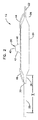
2.図1〜5に示す実施形態
カテーテルアセンブリ10の概要を図1〜8に例示的に示す。カテーテルアセンブリ10は、図6〜8に示す血管分岐部80のような血管分岐部の治療に用いられる。カテーテルアセンブリ10は、カテーテル主枝管12、カテーテル側枝管14、及びステント16を備える。カテーテル主枝管12は、基端部28及び先端部30を有するカテーテルシャフト20を備える。カテーテルシャフト20は、主膨張管腔32(図3)を形成している。カテーテル主枝管12は、主ガイドワイヤハウジング22をさらに有する。図3に示すように、主ガイドワイヤハウジング22は、主ガイドワイヤ管腔34を形成している。カテーテル主枝管12は、ガイドワイヤハウジング22に沿って延びる主バルーン24を備える。主バルーン24の基端側ウェスト部38はカテーテルシャフト20に動作可能に装着され、主バルーン24の先端側ウェスト部は主ガイドワイヤハウジング22に動作可能に装着される。
Other inconveniences include inconveniences related to the manufacturing process and manufacturing method of the main catheter branch 112. The formation of each joint 148, 170 requires time and additional steps. Since negligence can occur in any manufacturing process, monitoring to maintain quality is also necessary. Reducing the number of joints can reduce the overall time required for manufacturing and the number of steps in the manufacturing process, resulting in a reduction in manufacturing process costs and improved consistency. Further, by reducing the number of joints, extra parts of the assembly can be omitted. By combining the side balloon proximal end joint 148 and the main balloon proximal end joint 170 as described later, the
2. 1-5. An overview of the
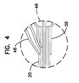
カテーテル主枝管12はさらに側バルーン26を備える。側バルーン26は、膨張可能部45、先端側ウェスト部44、及び基端側ウェスト部46を有する。ウェスト部材44、46は側膨張管腔45を形成し、この側膨張管腔45を介して膨張用流体が側バルーン26に供給される。先端側ウェスト部44の長さはL2であり、L2は約3〜15mm、好ましくは約6〜10mmである。基端側ウェスト部46の長さはL3であり、L3は約3〜15mm、好ましくは約6〜10mmである。側バルーン26は前側40及び後側42を有し、先端側ウェスト部44と基端側ウェスト部46はこれらの前側40及び後側42からそれぞれ延びる。非膨張時には、側バルーン26の膨張可能部45は折り畳まれた形状をなす(例えば、図1、6、及び7に示す折り畳まれた状態の側バルーン26)。膨張時には、側バルーン26の膨張可能部45は、主バルーン24の長手方向軸を基準として半径方向外方に延びる(図2、3、及び8参照)。
The
一般的に、先端側ウェスト部44の先端は、主バルーン24より先端側に位置する主ガイドワイヤ部材22に動作可能に装着される。先端側ウェスト部44の基端は、側バルーン26に動作可能に連通される。基端側ウェスト部46の先端も、側バルーン26に動作可能に連通される。基端側ウェスト部46の基端は、カテーテルシャフト20の先端部に動作可能に装着され、基端側接合部48において主膨張管腔32に連通する。主バルーン24も、主バルーン24の基端側ウェスト部38を介して、基端側接合部48において主膨張管腔32に連通する。基端側接合部48は、シャフト先端側セグメント120から距離L1だけ離れている。距離L1は、主バルーン24の基端側ウェスト部38の全長とほぼ同じ長さである。距離L1は、一般的に約1〜10mmであり、より好適には、約2〜5mmである。
Generally, the distal end of the distal
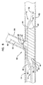
主膨張管腔32と側バルーン26を連通させるために、基端側ウェスト部46、カテーテルシャフト20の先端部30、及び主バルーンの基端側ウェスト部38が熱結合技術等により互いに対して同時に結合される。結合に先立ち、第1のマンドレル90がカテーテルシャフト30から側バルーンの基端側ウェスト部46に挿入され、第2のマンドレル92がカテーテルシャフト30から主バルーンの基端側ウェスト部38に挿入される(図5参照)。いくつかの構成においては、カテーテルシャフト20及び主バルーンの基端側ウェスト部38のどちらか一方もしくは両方にスリットが形成され、第2のマンドレルがカテーテルシャフト30から基端側ウェスト部46に挿入しやすくなっている。ある接合方法においては、第1及び第2のマンドレルが配置された状態で、基端側接合部48が加熱される。この加熱により、カテーテルシャフト20、側バルーンの基端側ウェスト部46、及び主バルーンの基端側ウェスト部38が互いに連通する。
In order to allow the
側バルーン26(基端側ウェスト部46を介する)と主バルーン24(基端側ウェスト部38を介する)とが単一の接合部において互いに結合し、それらが互いに、及び主膨張管腔32に対して連通する基端側接合部48を設けることにより、2つの基端側接合部を有するカテーテル主枝管112に比べてより多くの効果をもたらし得る。例えば、2つ以上の部材を互いに接合すると(例えばカテーテルシャフト20を主バルーン24又は側バルーン26のバルーンウェスト部に接合すると)、カテーテル主枝管12の剛性が高くなる場合が多いが、単一の基端側接合部において両方のバルーン24、26をカテーテルシャフト20に接合することにより、カテーテル主枝管112の先端部の可撓性を高めることが可能となる。カテーテル主枝管112の先端部の可撓性が高くなると、血管分岐部(図6〜8の血管分岐部80等)の治療時に、側バルーン26、及び主バルーン24に搬送されるステント16の構成要素が枝血管の小孔に対して半径方向に自己整合する可能性を向上することができる。また、カテーテルアセンブリ10がガイドワイヤ(後述するガイドワイヤ60、62等)上を血管分岐部の治療部位まで前進する際、カテーテルアセンブリ10が血管腔と干渉したり、ガイドワイヤがねじれたりすることにより、カテーテルアセンブリ10の先端が血管内で動かなくなってしまうことがある。このような場合、カテーテルアセンブリ10の前進や、枝血管の小孔に対する適宜な整合ができなくなる。しかし、バルーン24、26より基端側に位置する、カテーテル主枝管12の先端部30に回転可撓性及び曲げ可撓性をもたせることにより、カテーテルアセンブリ10を固定状態から自由にさせ、枝血管の小孔に対する半径方向の自己整合を促進することができる。
The side balloon 26 (via the proximal waist portion 46) and the main balloon 24 (via the proximal waist portion 38) are joined together at a single joint, and are connected to each other and to the
図1〜8に示すような単一の基端側接合部構成による効果の他の例としては、カテーテル主枝管12の製造プロセス及び製造方法に関する効果が挙げられる。基端側バルーン接合部を単一の接合部48に統合することにより、製造に要する全体的時間を短縮でき、製造プロセスの工程数を減らせる。その結果、コスト低減、ならびに、製造プロセスにおける整合性及び品質の向上が可能となる。さらに、基端側バルーン接合部の数を減らすことにより、シャフト先端側セグメント120等、アセンブリの余分な部品を省くことができる。このように部品数を減らすことにより、アセンブリのコストや製造プロセスの複雑性を抑えることが可能となる。
As another example of the effect of the single proximal side joint configuration as shown in FIGS. 1 to 8, there are the effects relating to the manufacturing process and manufacturing method of the catheter
カテーテル主枝管12の側バルーン基端側ウェスト部46において、ステント16の基端より基端側へ延びる長さは、カテーテル主枝管112の構成よりも短い。このように、基端側ウェスト部46においてカテーテル主枝管12のステント16の基端から基端側に延びる部分が短くなっているため、カテーテル主枝管12が体腔を通って分岐部の治療部位まで前進する前や前進中、さらにその後カテーテル主枝管12を体内から取り出す際に、この部分が何かに引っ掛かってしまう虞が低減されている。さらに、基端側接合部48と、主バルーンの先端側に位置するガイドワイヤハウジング22に先端側ウェスト部44が接合される箇所との距離が短くなっているため、血管分岐部を治療する際、ステント16の拡張前及び拡張時において、側バルーン26がステントの構成要素(ステントの側面枝開口部等)及び枝血管の小孔に対して正しく整合されなくなる虞が低減されている。
In the side balloon proximal
これらの効果は、本明細書に記載する単一の基端側バルーン接合部すなわち結合によりもたらされるものである。この単一の基端側バルーン接合部すなわち結合は、二重バルーン結合とも称される。この結合は、単一の結合プロセスにより単一の接合/結合箇所において2つのバルーンを(バルーンウェスト部38、46を介して)主膨張管腔32と連通するよう結合する工程であるからである。
3.図6〜8に図示する血管分岐部治療の例
図1〜6に示す前述のカテーテルアセンブリ10は、図6〜8に示すような血管分岐部80の治療に使用可能である。通常の場合、主血管ガイドワイヤ62は、血管分岐部80の主血管82内の、分岐部より先端側まで挿入される。枝血管ガイドワイヤ60は血管分岐部まで前進し、枝血管84への小孔すなわち開口86に挿入される。その後、主血管ガイドワイヤ62の基端が主ガイドワイヤ管腔34に挿入され、枝血管ガイドワイヤ60の基端がカテーテル側枝管14により形成される枝ガイドワイヤ管腔に挿入される。図6に示すように、カテーテルアセンブリ10はガイドワイヤ60、62上を血管分岐部まで前進する。そして、カテーテルアセンブリ10は、カテーテル側枝管14の基端部56が枝血管84内に配置されるまで先端側にさらに前進する。ステント16の側面枝開口部54が枝血管84への小孔86に対して半径方向及び軸方向に正しく整合しているか否かを確認するためには、マーカーシステムを用いることができる。マーカーシステムの例として、4マーカーシステムについて後述する。
These effects are provided by the single proximal balloon joint or bond described herein. This single proximal balloon junction or bond is also referred to as a double balloon bond. This is because the two balloons are joined in communication with the main inflation lumen 32 (via
3. Examples of Vascular Bifurcation Treatment Illustrated in FIGS. 6-8 The previously described
前述の通り、単一の基端側バルーン接合部48を設けることによりカテーテル主枝管12の先端部の可撓性が向上しているため、側バルーン26、及びステント16の側面枝開口部54の、小孔86に対する半径方向の自己整合が向上されている。カテーテルシャフト20の先端に位置する単一の基端側バルーン結合部48により、先端部30の領域Xにおいて単位長さ当たりのねじれが最大となっている(図2参照)。この領域Xは、従来例ではカテーテル主枝管112の2つの基端側バルーンが存在する領域である。
As described above, since the flexibility of the distal end portion of the
カテーテルアセンブリ10が正しい位置に配置されていることが確認されたのち、主バルーン24及び側バルーン26が膨張される。通常の場合、側バルーン26を膨張させると、側面枝開口部54を囲む拡張可能構造55も拡張する。拡張された拡張可能構造55は、小孔86を貫通して延び、枝血管84の少なくとも一部に延びる。
After confirming that the
後の工程においては、バルーン24、26が縮小されてカテーテル枝管12、14が取り除かれたのち、別のバルーン部材が枝血管84を治療すべく側面枝開口部54を経て前進し、枝血管84内において拡張可能構造55を開く。さらにその後の工程おいては、別の枝ステントが枝血管84の治療ために側面枝開口部54を経て枝血管84内に前進してもよい。
In a later step, after the
他の治療方法においては、上記の方法工程を変更してもよい。例えば、ガイドワイヤ60、62のどちらか一方をカテーテルアセンブリ10とともに血管分岐部まで前進させることもできる。別の実施形態においては、例えば枝血管への小孔に対する側面枝開口部54の整合を向上させるために、バルーン24、26を同時ではなく順番に膨張させてもよい。
In other treatment methods, the method steps described above may be altered. For example, one of the
カテーテルアセンブリ10は、X線や透視法により可視となるマーカー素材を含んでいてもよい。図6に、カテーテル主枝管12及びカテーテル側枝管14の先端部に沿って配置されたマーカー1〜4を示す。マーカー素材を含んだシステム10の構成要素はX線や透視法により容易に確認及び識別できる。マーカー素材の例としては、金、プラチナ、及びタングステンが挙げられる。ある実施形態においては、カテーテル主枝管12及びカテーテル側枝管14の少なくとも一方に固定された帯構造にマーカー素材が配される。他の実施形態においては、カテーテル主枝管12及びカテーテル側枝管14の一部分における材料組成の一部としてマーカー素材が配される。X線や透視法によりカテーテルアセンブリ10の構成要素が確認できると、システム10を操作する医師がより容易に血管分岐部80に対するシステム10の位置を調整できる。システム10に適したマーカー及びマーカー素材の例は、Vardiらに付与された米国特許第6、692、483号明細書、及び同時継続中の米国特許出願公開第2007/0203562号明細書「MARKER ARRANGEMENT FOR BIFURCATION CATHETER」に記載されている。
The
本明細書に開示するカテーテルアセンブリの実施形態においては、様々なステント、カテーテル、及びガイドワイヤの構成を用いることができる。本明細書に開示する発明は、特定の設計や構成に限定されない。本発明によるカテーテルアセンブリとともに使用可能なステントの例は、米国特許第6,210,429号明細書、米国特許第6,325,826号明細書、米国特許第6,706,062号明細書、 米国特許第7,220,275号明細書、及び米国特許出願公開第2004/0176837号明細書「SELF −EXPANDING STENT AND CATHETER ASSEMBLY AND METHOD FOR TREATING BIFURCATIONS」に記載されている。通常、前述のステントは、ステントの開口先端と開口基端との間に側面枝開口部を有している。この側面枝開口部は、ステントの内腔からステントの外の領域への経路を形成している。ステントの側面枝開口部は、ステントの側壁を形成するストラット構造のセル開口とは異なる開口である。いくつかのステントにおいては、拡張可能構造が側面枝開口部を囲む。この拡張可能構造は、例えば分岐部治療システムの膨張可能部が拡張した際に分岐部の枝管腔内に半径方向に延びるよう構成される。一般的に、ステントは、側面枝開口部が枝管腔への開口に対して整合された状態にて主管腔内に配置されてから拡張される。側面枝開口部は、枝管腔への開口に対して半径方向と軸方向の両方に整合される。ステントは、側面枝開口部を囲む拡張可能構造も含めて、1つ又は複数の拡張部材を用いて一回又は複数回の拡張により拡張可能である。 Various stent, catheter, and guidewire configurations can be used in the catheter assembly embodiments disclosed herein. The invention disclosed in this specification is not limited to a specific design or configuration. Examples of stents that can be used with a catheter assembly according to the present invention include US Pat. No. 6,210,429, US Pat. No. 6,325,826, US Pat. No. 6,706,062, U.S. Pat. No. 7,220,275, and U.S. Patent Application Publication No. 2004/0176837, “SELF-EXPANDING SENT AND CATTHESER ASSEMBLY AND METHOD FOR TREATING BIFRATIONS”. Usually, the above-mentioned stent has a side branch opening between the opening distal end and the opening proximal end of the stent. This side branch opening provides a path from the lumen of the stent to the area outside the stent. The side branch opening of the stent is an opening different from the cell opening of the strut structure that forms the side wall of the stent. In some stents, an expandable structure surrounds the side branch opening. The expandable structure is configured to extend radially into the branch lumen of the bifurcation when, for example, the expandable portion of the bifurcation treatment system is expanded. Generally, the stent is expanded after it is placed in the main lumen with the side branch openings aligned with the opening to the branch lumen. The side branch openings are aligned both radially and axially with respect to the opening to the branch lumen. The stent can be expanded by one or more expansions using one or more expansion members, including expandable structures surrounding the side branch openings.
本明細書に開示する主バルーン、側バルーン、及び他のバルーンは、準拠材料、非準拠材料、及びこれらの組み合わせを含んだ適宜なバルーン材料により形成可能である。本明細書に開示するバルーン及びカテーテルの材料の例としては、熱可塑性ポリマー、ポリエチレン(高密度、低密度、中間密度、鎖状低密度)、及び、ポリエチレン、イオノマー、ポリエステル、ポリカーボネート、ポリアミド、ポリ塩化ビニル、アクリルニトリルブタジエンスチレン共重合体、ポリエーテル−ポリエステル共重合体、ポリエーテル−ポリアミド共重合体等の様々な共重合体及び混合物が挙げられる。好適な材料の一例は、共重合ポリオレフィン材料であるSurlyn(登録商標)(デラウェア州ウィルミントン所在のデュポン ド ヌムール(Dupont de Nemours))である。さらに別の例としては、熱可塑性ポリマー及び熱硬化性ポリマー材料、ポリ(エチレンテレフタレート)(一般的にPETと称される)、熱可塑性ポリアミド、ポリフェニレンスルフィド、及びポリプロピレンが挙げられる。また別の例としては、ポリウレタン、及びポリアミド−ポリエーテルブロック共重合やアミド−テトラメチレングリコール共重合等のブロック共重合が挙げられる。別の例としては、PEBAX(登録商標) 70D、72D、2533、5533、6333、7033、又は7233 (米国ペンシルバニア州フィラデルフィア所在のエルフ アトケム(Elf Atochem)より入手可能)等のPEBAX(登録商標)(ポリアミド/ポリエーテル/ポリエステルブロック共重合)系のポリマーが挙げられる。別の例としては、脂肪質ナイロン等のナイロン、例えば、Vestamid(登録商標)L2101 IF、ナイロン 11 (エルフ アトケム(Elf Atochem))、ナイロン 6(アリード シグナル(Allied Signal))、ナイロン 6/10(ビーエーエスエフ(BASF)、ナイロン 6/12 (アシュリー ポリマー(Ashley Polymers)、ナイロン 12が挙げられる。他のナイロンの例としては、Grivory(登録商標)(イーエムエス(EMS))及びNylon MXD−6等の芳香性ナイロンが挙げられる。別のナイロンやナイロンの組み合わせも使用可能である。さらに別の例としては、CELANEX(登録商標)(ニュージャージー州サミット所在のティコナ(Ticona)から入手可能)等のポリブチレンテレフタレート(PBT)、例えばARNITEL(登録商標)EM740等のARNITEL(登録商標)(インディアナ州エリオンスピラ(Erionspilla)所在のディエスエム(DSM)から入手可能)等のポリエステル/エーテルブロック共重合体、Trogamid(PA6−3−T、デグサ)のような芳香族アミド、及びHYTREL(登録商標)(デラウェア州ウィルミントン所在のデュポン ド ヌムール(Dupont de Nemours))等の熱可塑性エラストマーが挙げられる。いくつかの実施形態において、PEBAX(登録商標)、HYTREL(登録商標)及びARNITEL(登録商標)は、約45D〜約82DのショアD硬度を有する。バルーン材料は、純粋な状態で用いてもよいし、または混合物として用いてもよい。例えば、混合物は、PBTと、RITEFLEX(登録商標)(ティコナから入手可能)、ARNITEL(登録商標)又はHYTREL(登録商標)等の1種以上のPBT熱可塑性エラストマーを含んでもよいし、もしくはポリエチレンテレフタレート(PET)と、PBT熱可塑性エラストマー等の熱可塑性エラストマーを含んでもよい。バルーン材料の他の例は、米国特許第6,146,356号明細書にも記載されている。
6.結論
本発明の一実施形態は、カテーテル主枝管及びカテーテル側枝管を備えるカテーテルアセンブリに関する。カテーテル主枝管は、カテーテルシャフト、主バルーン、及び側バルーンを有する。カテーテルシャフトは基端部及び先端部を有し、この先端部が主膨張部材を形成する。主バルーンは、先端に先端部ウェスト部を有し、基端に基端側ウェスト部を有する。側バルーンは、膨張可能部を有するとともに先端に先端部ウェスト部を有し、基端に基端側ウェスト部を有する。側バルーンは、側バルーン膨張時に主バルーンを基準として半径方向に延びるよう構成される。膨張可能部は主バルーンの基端部及び先端部の間の位置に設けられる。側バルーンの基端側ウェスト部及び主バルーンの基端側ウェスト部は、カテーテルシャフトの先端部に位置する基端側バルーン接合部において主膨張管腔に動作可能に連通する。
The main balloon, side balloon, and other balloons disclosed herein can be formed from any suitable balloon material including compliant materials, non-compliant materials, and combinations thereof. Examples of balloon and catheter materials disclosed herein include thermoplastic polymers, polyethylene (high density, low density, intermediate density, chain low density), and polyethylene, ionomer, polyester, polycarbonate, polyamide, poly Examples include various copolymers and mixtures such as vinyl chloride, acrylonitrile butadiene styrene copolymer, polyether-polyester copolymer, and polyether-polyamide copolymer. An example of a suitable material is Surlyn® (Dupont de Nemours, Wilmington, Del.), A copolymerized polyolefin material. Further examples include thermoplastic polymers and thermoset polymeric materials, poly (ethylene terephthalate) (commonly referred to as PET), thermoplastic polyamides, polyphenylene sulfide, and polypropylene. Another example includes polyurethane and block copolymerization such as polyamide-polyether block copolymerization and amide-tetramethylene glycol copolymerization. Another example is PEBAX®, such as PEBAX® 70D, 72D, 2533, 5533, 6333, 7033, or 7233 (available from Elf Atochem, Philadelphia, Pa.). (Polyamide / Polyether / Polyester block copolymer) type polymer may be mentioned. Other examples include nylons such as fatty nylons, such as Vestamid® L2101 IF, Nylon 11 (Elf Atochem), Nylon 6 (Allied Signal), Nylon 6/10 ( BASF, Nylon 6/12 (Ashley Polymers,
6). CONCLUSION One embodiment of the present invention relates to a catheter assembly comprising a main catheter branch and a side catheter branch. The main catheter branch has a catheter shaft, a main balloon, and a side balloon. The catheter shaft has a proximal end portion and a distal end portion, and the distal end portion forms a main inflation member. The main balloon has a distal end waist portion at the distal end and a proximal end waist portion at the proximal end. The side balloon has an inflatable portion, a distal end waist portion at the distal end, and a proximal end waist portion at the proximal end. The side balloon is configured to extend radially with respect to the main balloon when the side balloon is inflated. The inflatable portion is provided at a position between the proximal end portion and the distal end portion of the main balloon. The proximal end waist portion of the side balloon and the proximal end waist portion of the main balloon are operatively connected to the main inflation lumen at the proximal balloon junction located at the distal end of the catheter shaft.
本発明の別の実施形態は、カテーテル主枝管、カテーテル側枝管、及びステントを備えるカテーテルアセンブリに関する。カテーテル主枝管は、基端部及び先端部を有する。先端部は、カテーテルシャフト、主ガイドワイヤハウジング、及び主バルーンを有する。カテーテルシャフトは先端部を有し主膨張管腔を形成する。主ガイドワイヤハウジングはカテーテルシャフトの先端部を越えて先端側に延び、主ガイドワイヤ管腔を形成する。主バルーンは、基端側ウェスト部及び先端側ウェスト部を有する。側バルーンは、膨張可能部、基端側ウェスト部、及び先端側ウェスト部を有する。側バルーンの基端側ウェスト部及び先端側ウェスト部は側膨張管腔を形成する。側バルーンの基端側ウェスト部及び主バルーンの基端側ウェスト部は基端側バルーン接合部において主膨張管腔に連通するよう動作可能に装着される。カテーテル側枝管は先端部を有し、側ガイドワイヤ管腔を形成する。ステントは、開口基端、開口先端、及び側面枝開口部を有し、側面枝開口部は開口基端及び開口先端の間の位置においてステントに形成される。カテーテル側枝管の先端部は、主バルーン及び側バルーンの膨張に先立ち、側面枝開口部を貫通してカテーテル側枝管に延びる。 Another embodiment of the invention relates to a catheter assembly comprising a main catheter branch, a side catheter branch, and a stent. The main catheter branch has a proximal end and a distal end. The tip has a catheter shaft, a main guidewire housing, and a main balloon. The catheter shaft has a tip and forms a main inflation lumen. The main guidewire housing extends distally beyond the distal end of the catheter shaft and forms a main guidewire lumen. The main balloon has a proximal waist portion and a distal waist portion. The side balloon has an inflatable portion, a proximal waist portion, and a distal waist portion. The proximal side waist portion and the distal side waist portion of the side balloon form a side inflation lumen. The proximal end waist portion of the side balloon and the proximal end waist portion of the main balloon are operatively mounted to communicate with the main inflation lumen at the proximal end balloon junction. The side catheter branch has a tip and forms a side guidewire lumen. The stent has an open proximal end, an open distal end, and a side branch opening, and the side branch opening is formed in the stent at a position between the open proximal end and the open distal end. The distal end of the side catheter branch extends through the side branch opening to the side catheter branch prior to inflation of the main and side balloons.
本発明のさらに別の実施形態は、カテーテルアセンブリの製造方法に関する。このカテーテルアセンブリは、カテーテルシャフトと主バルーンと側バルーンとを有するカテーテル主枝管を備える。カテーテルシャフトは先端部を有するとともに主膨張管腔を形成する。主バルーンは主バルーンの基端部に基端側ウェスト部を有するとともに主バルーンの先端部に先端側ウェスト部を有する。側バルーンは、膨張可能部及びこの膨張可能部より基端側に延びる基端側ウェスト部を有する。膨張可能部は、主バルーンの基端側ウェスト部及び先端側ウェスト部の間の位置に配置される。側バルーンが膨張されると膨張可能部は主バルーンを基準として半径方向に延びる。この方法は、側バルーンの基端側ウェスト部の開口基端、及び主バルーンの基端側ウェスト部の開口基端を、互いに近接するよう配置するとともにカテーテルシャフトの先端部において主膨張管腔に対して連通するよう配置する工程と、側バルーンの基端側ウェスト部、主バルーンの基端側ウェスト部、及び主膨張管腔が互いに連通した状態を保ちつつ、側バルーンの基端側ウェスト部、主バルーンの基端側ウェスト部、及びカテーテルシャフトの先端部を基端側バルーン接合部においてともに固定する固定工程を含む。 Yet another embodiment of the invention relates to a method of manufacturing a catheter assembly. The catheter assembly includes a main catheter branch having a catheter shaft, a main balloon, and a side balloon. The catheter shaft has a distal portion and forms a main inflation lumen. The main balloon has a proximal side waist portion at the proximal end portion of the main balloon and a distal side waist portion at the distal end portion of the main balloon. The side balloon has an inflatable portion and a proximal-side waist portion extending proximally from the inflatable portion. The inflatable part is disposed at a position between the proximal side waist part and the distal side waist part of the main balloon. When the side balloon is inflated, the inflatable portion extends radially with respect to the main balloon. In this method, the proximal end of the proximal end of the side balloon and the proximal end of the proximal end of the main balloon are disposed so as to be close to each other, and at the distal end of the catheter shaft, the main inflation lumen is formed. A proximal end waist portion of the side balloon while maintaining a state in which the proximal end waist portion of the side balloon, the proximal end waist portion of the main balloon, and the main inflation lumen communicate with each other. And a fixing step of fixing the proximal side waist portion of the main balloon and the distal end portion of the catheter shaft together at the proximal side balloon joint portion.
本明細書に記載される全ての要素を含んでいない構成又であっても、本発明の効果をもたらし得ることに留意されたい。 It should be noted that a configuration that does not include all of the elements described herein can produce the effects of the present invention.
Claims (13)
前記カテーテル主枝管が、
基端部及び先端部を有し、該先端部が主膨張管腔を形成するカテーテルシャフトであって、同カテーテルシャフトは、先端部を有するとともに主ガイドワイヤ管腔を形成する主ガイドワイヤハウジングを有し、該主ガイドワイヤハウジングの先端部は、前記カテーテルシャフトの先端部を越えて先端側に延びる、前記カテーテルシャフトと、
先端部に先端側ウェスト部を有するとともに基端部に基端側ウェスト部を有する主バルーンであって、該基端側ウェスト部は前記カテーテルシャフトに装着され、該先端側ウェスト部は、前記主ガイドワイヤハウジングの先端部に装着される、前記主バルーンと、
膨張可能部を有し、先端部に先端側ウェスト部を有するとともに基端部に基端側ウェスト部を有する側バルーンと、を有し、
前記側バルーンが膨張されると側バルーンが主バルーンを基準として半径方向に延び、前記膨張可能部が主バルーンの基端部及び先端部の間の位置に配置され、前記側バルーンの基端側ウェスト部、主バルーンの基端側ウェスト部、及びカテーテルシャフトの先端部は、前記側バルーン及び主バルーンが、前記カテーテルシャフトの先端部から前記主バルーンの基端側ウェスト部の長さと同じ距離だけ離間する単一の基端側バルーン接合部において前記カテーテルシャフトの主膨張管腔に連通するように、単一の接合部にて結合され、
前記カテーテルシャフトの前記先端部は、同カテーテルシャフトの先端部が前記主バルーンの基端側ウェスト部の先端部に配置されるように主バルーンの基端側ウェスト部内を延びることを特徴とするカテーテルアセンブリ。 In a catheter assembly comprising a main catheter branch,
The main catheter branch is
A catheter shaft having a proximal end and a distal end, wherein the distal end forms a main inflation lumen, the catheter shaft having a main guidewire housing having a distal end and forming a main guidewire lumen And the distal end portion of the main guide wire housing extends to the distal end side beyond the distal end portion of the catheter shaft, and
A main balloon having a distal side waist portion at a distal end portion and a proximal side waist portion at a proximal end portion, wherein the proximal end waist portion is attached to the catheter shaft; The main balloon, which is attached to the distal end of the guide wire housing;
A side balloon having an inflatable portion, having a distal side waist portion at a distal end portion and having a proximal side waist portion at a proximal end portion;
When the side balloon is inflated, the side balloon extends in a radial direction with respect to the main balloon, and the inflatable portion is disposed at a position between the proximal end portion and the distal end portion of the main balloon. The waist part, the proximal side waist part of the main balloon, and the distal end part of the catheter shaft are the same distance as the length of the proximal side waist part of the main balloon from the distal end part of the catheter shaft. at the proximal end side balloon joint single spaced apart so as to communicate with the main inflation lumen of the catheter shaft, it is attached at a single junction,
The distal end of the catheter shaft, a catheter, wherein a distal portion of the catheter shaft extends proximal waste portion of the main balloon so as to be disposed at the distal end of the proximal waste of the main balloon assembly.
前記側バルーンの基端側ウェスト部の開口基端、及び前記主バルーンの基端側ウェスト部の開口基端を、互いに近接するよう配置するとともに前記カテーテルシャフトの先端部において主膨張管腔に連通するよう配置する工程であって、前記カテーテルシャフトの先端部は、同カテーテルシャフトの先端部が前記主バルーンの基端側ウェスト部の先端部に配置されるように主バルーンの基端側ウェスト部内に位置される、前記配置工程と、
前記側バルーンの基端側ウェスト部、主バルーンの基端側ウェスト部、及び主膨張管腔が互いに連通した状態を保ちつつ、前記側バルーンの基端側ウェスト部、主バルーンの基端側ウェスト部、及びカテーテルシャフトの先端部を、前記カテーテルシャフトの前記先端部から前記主バルーンの基端側ウェスト部の長さと同じ距離だけ離間する単一の基端側バルーン接合部においてともに固定する固定工程と、からなることを特徴とする方法。 A main catheter branch having a catheter shaft, a main balloon, and a side balloon, wherein the catheter shaft has a distal end portion and forms a main inflation lumen, and the main balloon is proximal to the proximal end portion of the main balloon; And a distal side waist portion at the distal end portion of the main balloon, the side balloon having an inflatable portion and a proximal side waist portion extending proximally from the inflatable portion, wherein the inflatable portion is In a method of manufacturing a catheter assembly disposed between a proximal waist portion and a distal waist portion of a main balloon, wherein the inflatable portion extends radially with respect to the main balloon when the side balloon is inflated.
An opening proximal end of the proximal end waist portion of the side balloon and an opening proximal end of the proximal end waist portion of the main balloon are arranged so as to be close to each other and communicated with the main inflation lumen at the distal end portion of the catheter shaft The distal end portion of the catheter shaft is disposed in the proximal end waist portion of the main balloon such that the distal end portion of the catheter shaft is disposed at the distal end portion of the proximal end waist portion of the main balloon. Located in the step,
The proximal side waist part of the side balloon, the proximal side waist part of the main balloon, and the proximal side waist part of the main balloon And a fixing step of fixing the distal end portion of the catheter shaft and the distal end portion of the catheter shaft together at a single proximal balloon joining portion that is separated from the distal end portion of the catheter shaft by the same distance as the length of the proximal end waist portion of the main balloon. And a method characterized by comprising:
12のいずれか一項に記載の方法。 The method according to any one of claims 8 to 12, wherein the fixing step includes a step of applying an adhesive and a step of curing the adhesive.
Applications Claiming Priority (3)
| Application Number | Priority Date | Filing Date | Title |
|---|---|---|---|
| US12/183,869 | 2008-07-31 | ||
| US12/183,869 US8163123B2 (en) | 2008-07-31 | 2008-07-31 | Bifurcation catheter dual balloon bond and methods |
| PCT/US2009/052135 WO2010014734A1 (en) | 2008-07-31 | 2009-07-29 | Bifurcation catheter dual balloon bond and methods |
Publications (3)
| Publication Number | Publication Date |
|---|---|
| JP2011529739A JP2011529739A (en) | 2011-12-15 |
| JP2011529739A5 JP2011529739A5 (en) | 2012-11-15 |
| JP5844152B2 true JP5844152B2 (en) | 2016-01-13 |
Family
ID=41090295
Family Applications (1)
| Application Number | Title | Priority Date | Filing Date |
|---|---|---|---|
| JP2011521296A Expired - Fee Related JP5844152B2 (en) | 2008-07-31 | 2009-07-29 | Dual balloon coupling and coupling method of branch catheter |
Country Status (4)
| Country | Link |
|---|---|
| US (2) | US8163123B2 (en) |
| EP (1) | EP2344091A1 (en) |
| JP (1) | JP5844152B2 (en) |
| WO (1) | WO2010014734A1 (en) |
Families Citing this family (33)
| Publication number | Priority date | Publication date | Assignee | Title |
|---|---|---|---|---|
| ES2845146T3 (en) | 2006-10-09 | 2021-07-26 | Neurofluidics Inc | Cerebrospinal fluid purification system |
| US10850235B2 (en) | 2006-10-09 | 2020-12-01 | Minnetronix, Inc. | Method for filtering cerebrospinal fluid (CSF) including monitoring CSF flow |
| US10632237B2 (en) | 2006-10-09 | 2020-04-28 | Minnetronix, Inc. | Tangential flow filter system for the filtration of materials from biologic fluids |
| US20100030192A1 (en) * | 2008-08-01 | 2010-02-04 | Boston Scientific Scimed, Inc. | Catheter shaft bond arrangements and methods |
| US20130081209A1 (en) | 2011-09-30 | 2013-04-04 | Nomaco Inc. | Cellular mattress assemblies and related methods |
| US20120272457A1 (en) | 2011-04-29 | 2012-11-01 | Nomaco Inc. | Unitary composite/hybrid cushioning structure(s) and profile(s) comprised of a thermoplastic foam(s) and a thermoset material(s) and related methods |
| US8261558B2 (en) * | 2009-06-25 | 2012-09-11 | Nomaco Inc. | Self-adjusting insulation, including insulation particularly suited for pipe or duct |
| USD694553S1 (en) | 2010-03-03 | 2013-12-03 | Noel Group Llc | Mattress bed cushion |
| USD693144S1 (en) | 2010-03-03 | 2013-11-12 | Noel Group Llc | Mattress bed cushion |
| USD693148S1 (en) | 2010-03-03 | 2013-11-12 | Noel Group Llc | Mattress bed cushion |
| USD693145S1 (en) | 2010-03-03 | 2013-11-12 | Noel Group Llc | Mattress bed cushion |
| USD688492S1 (en) | 2010-03-03 | 2013-08-27 | Noel Group Llc | Mattress bed cushion |
| USD691400S1 (en) | 2012-02-10 | 2013-10-15 | Nomaco Inc. | Stackable base for mattress assembly |
| USD692693S1 (en) | 2012-04-27 | 2013-11-05 | Noel Group Llc | Mattress bed cushion |
| USD693146S1 (en) | 2012-04-27 | 2013-11-12 | Noel Group Llc | Mattress bed cushion |
| USD693147S1 (en) | 2012-04-27 | 2013-11-12 | Noel Group Llc | Mattress bed cushion |
| USD694552S1 (en) | 2012-04-27 | 2013-12-03 | Noel Group Llc | Mattress bed cushion |
| USD693149S1 (en) | 2012-04-27 | 2013-11-12 | Noel Group Llc | Mattress bed cushion |
| EP2847508A4 (en) | 2012-05-11 | 2016-01-20 | Nomaco Inc | Insulation systems employing expansion features to insulate elongated containers subject to extreme temperature fluctuations, and related components and methods |
| USD697337S1 (en) | 2012-07-03 | 2014-01-14 | Nomaco, Inc. | Stackable base for mattress assembly |
| USD690536S1 (en) | 2012-07-26 | 2013-10-01 | Nomaco Inc. | Motion isolation insulator pad |
| USD692694S1 (en) | 2012-09-28 | 2013-11-05 | Noel Group Llc | Mattress bed cushion |
| USD694041S1 (en) | 2012-09-28 | 2013-11-26 | Noel Group Llc | Mattress bed cushion |
| USD688069S1 (en) | 2012-09-28 | 2013-08-20 | Noel Group Llc | Mattress bed cushion |
| USD709301S1 (en) | 2012-11-09 | 2014-07-22 | Noel Group Llc | Mattress bed cushion |
| USD701713S1 (en) | 2012-11-09 | 2014-04-01 | Noel Group, Llc | Mattress bed cushion |
| USD707468S1 (en) | 2012-11-09 | 2014-06-24 | Noel Group Llc | Mattress bed cushion |
| USD707467S1 (en) | 2012-11-09 | 2014-06-24 | Noel Group Llc | Mattress bed cushion |
| WO2014176400A1 (en) | 2013-04-26 | 2014-10-30 | Noel Group Llc | Cushioning assemblies with thermoplastic elements encapsulated in thermoset providing customizable support and airflow, and related methods |
| USD704962S1 (en) | 2013-09-09 | 2014-05-20 | Noel Group Llc | Mattress bed cushion |
| US10709587B2 (en) * | 2013-11-05 | 2020-07-14 | Hameem Unnabi Changezi | Bifurcated stent and delivery system |
| US11147540B2 (en) | 2015-07-01 | 2021-10-19 | Minnetronix, Inc. | Introducer sheath and puncture tool for the introduction and placement of a catheter in tissue |
| JP6654242B2 (en) | 2015-12-04 | 2020-02-26 | ミネトロニクス, インコーポレイテッド | System for treating cerebrospinal fluid |
Family Cites Families (18)
| Publication number | Priority date | Publication date | Assignee | Title |
|---|---|---|---|---|
| JP2832722B2 (en) * | 1989-01-27 | 1998-12-09 | ヴァス―カス・インコーポレイテッド | Multi-lumen catheter |
| DE69403461T2 (en) * | 1993-03-16 | 1998-01-15 | Med Pro Design Inc | CATHETER AND MANUFACTURING METHOD |
| FR2733682B1 (en) * | 1995-05-04 | 1997-10-31 | Dibie Alain | ENDOPROSTHESIS FOR THE TREATMENT OF STENOSIS ON BIFURCATIONS OF BLOOD VESSELS AND LAYING EQUIPMENT THEREFOR |
| US6692483B2 (en) | 1996-11-04 | 2004-02-17 | Advanced Stent Technologies, Inc. | Catheter with attached flexible side sheath |
| ATE539702T1 (en) | 1996-11-04 | 2012-01-15 | Advanced Stent Tech Inc | DEVICE FOR EXPANDING A STENT AND METHOD FOR DEPLOYING IT |
| US7220275B2 (en) | 1996-11-04 | 2007-05-22 | Advanced Stent Technologies, Inc. | Stent with protruding branch portion for bifurcated vessels |
| US6325826B1 (en) | 1998-01-14 | 2001-12-04 | Advanced Stent Technologies, Inc. | Extendible stent apparatus |
| US6129707A (en) * | 1998-01-21 | 2000-10-10 | Advanced Cardiovascular Systems, Inc. | Intravascular catheter with expanded distal tip |
| US7655030B2 (en) * | 2003-07-18 | 2010-02-02 | Boston Scientific Scimed, Inc. | Catheter balloon systems and methods |
| US6409863B1 (en) * | 2000-06-12 | 2002-06-25 | Scimed Life Systems, Inc. | Methods of fabricating a catheter shaft having one or more guidewire ports |
| US6575934B2 (en) * | 2000-12-21 | 2003-06-10 | Advanced Cardiovascular Systems, Inc. | Low profile catheter |
| US20040176837A1 (en) * | 2001-05-17 | 2004-09-09 | Atladottir Svava Maria | Self-expanding stent and catheter assembly and method for treating bifurcations |
| US6902571B2 (en) * | 2002-08-29 | 2005-06-07 | Advanced Cardiovascular Systems, Inc. | Compacted catheter balloon and method of incremental compaction |
| US7344557B2 (en) * | 2003-11-12 | 2008-03-18 | Advanced Stent Technologies, Inc. | Catheter balloon systems and methods |
| US8298179B2 (en) * | 2004-12-22 | 2012-10-30 | Boston Scientific Scimed, Inc. | Catheter assembly with tapered joints and method of manufacture |
| US7901395B2 (en) * | 2005-08-16 | 2011-03-08 | Borden Jonathan R | Catheter having staggered lumens and method |
| US8821561B2 (en) | 2006-02-22 | 2014-09-02 | Boston Scientific Scimed, Inc. | Marker arrangement for bifurcation catheter |
| US8747456B2 (en) | 2007-12-31 | 2014-06-10 | Boston Scientific Scimed, Inc. | Bifurcation stent delivery system and methods |
-
2008
- 2008-07-31 US US12/183,869 patent/US8163123B2/en not_active Expired - Fee Related
-
2009
- 2009-07-29 EP EP09790949A patent/EP2344091A1/en not_active Withdrawn
- 2009-07-29 JP JP2011521296A patent/JP5844152B2/en not_active Expired - Fee Related
- 2009-07-29 WO PCT/US2009/052135 patent/WO2010014734A1/en active Application Filing
-
2012
- 2012-04-23 US US13/453,000 patent/US20120209367A1/en not_active Abandoned
Also Published As
| Publication number | Publication date |
|---|---|
| WO2010014734A1 (en) | 2010-02-04 |
| US20120209367A1 (en) | 2012-08-16 |
| EP2344091A1 (en) | 2011-07-20 |
| US20100030316A1 (en) | 2010-02-04 |
| JP2011529739A (en) | 2011-12-15 |
| US8163123B2 (en) | 2012-04-24 |
Similar Documents
| Publication | Publication Date | Title |
|---|---|---|
| JP5844152B2 (en) | Dual balloon coupling and coupling method of branch catheter | |
| US8398697B2 (en) | Bifurcation catheter assembly with distally mounted side balloon and methods | |
| US6258073B1 (en) | Bifurcated catheter assembly | |
| US7842056B2 (en) | Cutting member for bifurcation catheter assembly | |
| US8343181B2 (en) | Method and apparatus for treating stenoses at bifurcated regions | |
| US8292900B2 (en) | Side branch wiring assist sheath and methods | |
| US8246670B2 (en) | Catheter system and method for delivering medical devices | |
| US20090204083A1 (en) | Method and Apparatus for Treating Stenoses at Bifurcated Regions | |
| EP2296590A1 (en) | Bifurcation stent crimping systems and methods | |
| US8518103B2 (en) | Bifurcated delivery system and method | |
| US8966740B2 (en) | Joined inflation portions for bifurcation catheter | |
| JP5555232B2 (en) | Bifurcated catheter assembly and method | |
| US8945198B2 (en) | Locating side catheter branch relative to inflation portion |
Legal Events
| Date | Code | Title | Description |
|---|---|---|---|
| A621 | Written request for application examination |
Free format text: JAPANESE INTERMEDIATE CODE: A621 Effective date: 20120723 |
|
| A521 | Request for written amendment filed |
Free format text: JAPANESE INTERMEDIATE CODE: A523 Effective date: 20120928 |
|
| A977 | Report on retrieval |
Free format text: JAPANESE INTERMEDIATE CODE: A971007 Effective date: 20130718 |
|
| A131 | Notification of reasons for refusal |
Free format text: JAPANESE INTERMEDIATE CODE: A131 Effective date: 20130723 |
|
| A521 | Request for written amendment filed |
Free format text: JAPANESE INTERMEDIATE CODE: A523 Effective date: 20131023 |
|
| A02 | Decision of refusal |
Free format text: JAPANESE INTERMEDIATE CODE: A02 Effective date: 20140401 |
|
| A521 | Request for written amendment filed |
Free format text: JAPANESE INTERMEDIATE CODE: A523 Effective date: 20140725 |
|
| A911 | Transfer to examiner for re-examination before appeal (zenchi) |
Free format text: JAPANESE INTERMEDIATE CODE: A911 Effective date: 20140805 |
|
| A61 | First payment of annual fees (during grant procedure) |
Free format text: JAPANESE INTERMEDIATE CODE: A61 Effective date: 20151118 |
|
| R150 | Certificate of patent or registration of utility model |
Ref document number: 5844152 Country of ref document: JP Free format text: JAPANESE INTERMEDIATE CODE: R150 |
|
| LAPS | Cancellation because of no payment of annual fees |