JP5844112B2 - Solar panel installation structure and solar panel installation construction method - Google Patents
Solar panel installation structure and solar panel installation construction method Download PDFInfo
- Publication number
- JP5844112B2 JP5844112B2 JP2011226474A JP2011226474A JP5844112B2 JP 5844112 B2 JP5844112 B2 JP 5844112B2 JP 2011226474 A JP2011226474 A JP 2011226474A JP 2011226474 A JP2011226474 A JP 2011226474A JP 5844112 B2 JP5844112 B2 JP 5844112B2
- Authority
- JP
- Japan
- Prior art keywords
- slope
- solar panel
- panel
- solar
- panel receiving
- Prior art date
- Legal status (The legal status is an assumption and is not a legal conclusion. Google has not performed a legal analysis and makes no representation as to the accuracy of the status listed.)
- Expired - Fee Related
Links
Images


Classifications
-
- F—MECHANICAL ENGINEERING; LIGHTING; HEATING; WEAPONS; BLASTING
- F24—HEATING; RANGES; VENTILATING
- F24S—SOLAR HEAT COLLECTORS; SOLAR HEAT SYSTEMS
- F24S25/00—Arrangement of stationary mountings or supports for solar heat collector modules
- F24S25/10—Arrangement of stationary mountings or supports for solar heat collector modules extending in directions away from a supporting surface
- F24S25/12—Arrangement of stationary mountings or supports for solar heat collector modules extending in directions away from a supporting surface using posts in combination with upper profiles
-
- F—MECHANICAL ENGINEERING; LIGHTING; HEATING; WEAPONS; BLASTING
- F24—HEATING; RANGES; VENTILATING
- F24S—SOLAR HEAT COLLECTORS; SOLAR HEAT SYSTEMS
- F24S25/00—Arrangement of stationary mountings or supports for solar heat collector modules
- F24S25/30—Arrangement of stationary mountings or supports for solar heat collector modules using elongate rigid mounting elements extending substantially along the supporting surface, e.g. for covering buildings with solar heat collectors
- F24S25/33—Arrangement of stationary mountings or supports for solar heat collector modules using elongate rigid mounting elements extending substantially along the supporting surface, e.g. for covering buildings with solar heat collectors forming substantially planar assemblies, e.g. of coplanar or stacked profiles
-
- Y—GENERAL TAGGING OF NEW TECHNOLOGICAL DEVELOPMENTS; GENERAL TAGGING OF CROSS-SECTIONAL TECHNOLOGIES SPANNING OVER SEVERAL SECTIONS OF THE IPC; TECHNICAL SUBJECTS COVERED BY FORMER USPC CROSS-REFERENCE ART COLLECTIONS [XRACs] AND DIGESTS
- Y02—TECHNOLOGIES OR APPLICATIONS FOR MITIGATION OR ADAPTATION AGAINST CLIMATE CHANGE
- Y02E—REDUCTION OF GREENHOUSE GAS [GHG] EMISSIONS, RELATED TO ENERGY GENERATION, TRANSMISSION OR DISTRIBUTION
- Y02E10/00—Energy generation through renewable energy sources
- Y02E10/40—Solar thermal energy, e.g. solar towers
- Y02E10/47—Mountings or tracking
-
- Y—GENERAL TAGGING OF NEW TECHNOLOGICAL DEVELOPMENTS; GENERAL TAGGING OF CROSS-SECTIONAL TECHNOLOGIES SPANNING OVER SEVERAL SECTIONS OF THE IPC; TECHNICAL SUBJECTS COVERED BY FORMER USPC CROSS-REFERENCE ART COLLECTIONS [XRACs] AND DIGESTS
- Y02—TECHNOLOGIES OR APPLICATIONS FOR MITIGATION OR ADAPTATION AGAINST CLIMATE CHANGE
- Y02E—REDUCTION OF GREENHOUSE GAS [GHG] EMISSIONS, RELATED TO ENERGY GENERATION, TRANSMISSION OR DISTRIBUTION
- Y02E10/00—Energy generation through renewable energy sources
- Y02E10/50—Photovoltaic [PV] energy
Description
この発明は、土手などの斜面に太陽光パネルを設置するための太陽光パネル設置構造 、及び太陽光パネル設置施工方法に関する。 The present invention relates to a solar panel installation structure for installing a solar panel on a slope such as a bank and a solar panel installation construction method.
太陽光パネルを屋外に設置する場合、太陽光を効果的に受光するために傾けて設置するが、河川沿いの土手や盛土された道路の側部法面などの斜面は、その向きが太陽光パネルの受光に不適当でなければ太陽光パネルを設置するスペースとして好適である。このような斜面に太陽光パネルを設置する場合、斜面に設けた基礎部に太陽光パネル設置架台を設け、その上に太陽光パネルを設置して、太陽光パネルと斜面(地面)との間に空間を形成する。 When installing solar panels outdoors, they are installed at an angle to effectively receive sunlight, but the direction of slopes such as banks along rivers and side slopes of embanked roads is sunlight. If it is not suitable for light reception of the panel, it is suitable as a space for installing a solar panel. When installing a solar panel on such a slope, install a solar panel installation base on the foundation provided on the slope, and install a solar panel on it, between the solar panel and the slope (ground) To form a space.
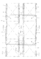
太陽光発電装置は一般に、太陽光パネル設置架台に複数の太陽光パネルを取り付ける。 従来、各太陽光パネルを太陽光パネル設置架台に取り付ける場合、図12(イ)、(ロ)に示すように、各太陽光パネル51を太陽光パネル設置架台52の所定の箇所に直接に配置して、ボルト53等で取り付けるのが一般的である(特許文献1の図3)。51aは太陽光パネルの周囲の枠材、51bは太陽電池モジュールである。図示例では15枚の太陽光パネル51を縦横に隣接させて設置している。
Generally, a solar power generation apparatus attaches a plurality of solar panels to a solar panel installation base. Conventionally, when each solar panel is attached to a solar panel installation base, each
図13(イ)、(ロ)に示すように、太陽光パネル61を太陽光パネル設置架台62の架台フレーム63上でスライドさせて所定の箇所に位置させる構造のものもある(特許文献1の図1、図2)。
この太陽光パネル設置架台62は、開口部が互いに向き合って平行に配設され傾斜した断面コ字形の架台フレーム63と、両架台フレーム63の下端部に設けられたストッパ64と、両架台フレーム63の下辺に形成された複数個の螺孔65と、螺孔65に下方から挿入されて螺合し先端が太陽光パネル61の枠材61aを架台フレーム63上辺に押圧するボルト66とを備えた構造である。61bは太陽電池モジュールである。図示例では傾斜した横並びの2つの太陽光パネル設置架台62のそれぞれに3枚の太陽光パネル61を縦に隣接させて設置している。
この太陽光パネル設置架台62は、架台フレーム63が断面コ字形で開口部が互いに向き合って平行に配設されているため、太陽光パネル61の両側を太陽光パネル設置架台62の両架台フレーム63間に順次に挿入することができ、その上、架台フレーム63の下辺の螺孔65に螺合したボルト66の先端でパネル61を架台フレーム63の上辺に押圧するため、従来のようにボルトの挿通孔を合わせる必要がなく、ボルトの数も少なく、取付作業が容易であり、かつ、パネルを下方からのボルトにより押し上げて固定しているため、パネルの取付強度が大である、という効果を奏する。
As shown in FIGS. 13 (a) and 13 (b), there is a structure in which the
The solar
In this solar panel installation stand 62, since the
図12の太陽光パネル設置架台52ように、複数の太陽光パネルを、太陽光パネル設置架台の所定の箇所に直接に配置して、ボルトで取り付ける従来の一般的な太陽光パネル設置構造では、太陽光パネルを太陽光パネル設置架台にボルトで取り付ける作業をする際、太陽光パネルの下に潜り込んで取り付け作業をする必要が生じるケースが多いが、そのような作業は極めて作業性が悪い。また、潜り込むこと自体及び潜ってする作業によってケガなどする恐れもある。
また、傾斜した架台に太陽光パネルを設置する際に、架台に置いてボルトで固定する前の段階で太陽光パネルが滑落する恐れがある。
また、太陽光パネルと斜面との間に若干の空間(高さ空間)は必要であるが、太陽光パネルの下に潜って作業する必要のある構造の場合には、前記空間を必要以上に高く形成することが必要となり、架台を支持する脚を高くする必要がある。このため、長い脚材が必要となり、鋼材の使用量が多くなり、材料コストが高くなる。
In the conventional general solar panel installation structure in which a plurality of solar panels are arranged directly at predetermined positions of the solar panel installation base and attached with bolts, as in the solar
Moreover, when installing a solar panel on an inclined base, the solar panel may slide down before being placed on the base and fixed with bolts.
In addition, although a slight space (height space) is required between the solar panel and the slope, in the case of a structure that needs to work under the solar panel, the space is more than necessary. It is necessary to make it high, and it is necessary to raise the legs that support the gantry. For this reason, a long leg is required, the amount of steel used is increased, and the material cost is increased.
図13の太陽光パネル設置架台62のように、複数の太陽光パネル61を、対向する一対の架台フレーム63間に傾斜上側から順次挿入しスライドさせて所定箇所に位置させ、最初に挿入した太陽光パネルは傾斜下側のストッパ64で受け止めるとともに、各太陽光パネルの枠材61aを架台フレーム63の下辺側から捻じ込んだボルト66で上辺に押圧して固定するものは、ボルトとナットとによる締結作業がない点では作業性はよいが、中央の架台フレーム63においては太陽光パネル61の下面に潜ってするボルト締め付け作業が必要で、この点では作業性がよいとは言えない。また、太陽光パネルの枠材を架台フレームの上辺にボルトで押圧するだけでは、いずれガタが生じる恐れがあり太陽光パネルを堅固に固定することはできない。
また、例えば故障した太陽光パネルを取り替える際に、複数設置された太陽光パネルの任意の1枚を取り外すことができず、メンテナンス等の際の作業性に欠ける。
また、図示例は縦並びの太陽光パネルを横方向に2列配置した場合であるが、横方向に3列さらには多数列置した場合、横方向の中間に位置する太陽光パネルについては、太陽光パネルに潜ってする作業がかなり多くなり、作業性が悪くなる。それを避けようとすると横方向の列数を多くはできず、一基の太陽光パネル設置構造に配置できる太陽光パネルの数を多くすることができない。また、例えば土手などのように横方向に延びる斜面の場合に、太陽光パネルを横方向に多数配置することはできない。
As in the solar
Further, for example, when replacing a failed solar panel, any one of a plurality of installed solar panels cannot be removed, and workability during maintenance or the like is lacking.
In addition, the illustrated example is a case where two rows of vertically arranged solar panels are arranged in the horizontal direction, but when three rows or more rows are arranged in the horizontal direction, the solar panels located in the middle in the horizontal direction are There is a considerable amount of work diving in the solar panel, and the workability deteriorates. If it tries to avoid it, the number of rows in the horizontal direction cannot be increased, and the number of solar panels that can be arranged in one solar panel installation structure cannot be increased. In addition, in the case of a slope extending in the horizontal direction such as a bank, a large number of solar panels cannot be arranged in the horizontal direction.
本発明は上記従来の欠点を解消するためになされたもので、太陽光パネルをボルトで架台に堅固に固定する構造を採用するがボルト締めのために太陽光パネルの下に潜り込んでする作業を不要にして、太陽光パネル設置作業の作業性を向上させることができ、ケガなどする恐れもなくし、太陽光パネルと斜面との間の高さ空間を最小限にとどめることが可能で架台を支持する脚部ないし基礎部を低くし材料コストを安くすることができ、また、太陽光パネルを架台に置いてボルトで固定する前の段階で太陽光パネルが滑落する恐れがなく、また、複数設置された太陽光パネルの任意の1枚を容易に取り外すことが可能としてメンテナンスなどの作業を容易にし、さらに、土手などの横方向に延びる斜面に設置する際に横方向に多数設置することが可能な太陽光パネル設置構造及び太陽光パネル設置施工方法を提供することを目的とする。 The present invention has been made to eliminate the above-mentioned conventional drawbacks, and employs a structure in which the solar panel is firmly fixed to the gantry with bolts. Eliminates the need to improve the workability of solar panel installation work, eliminates the risk of injury, and minimizes the height space between the solar panel and the slope and supports the stand Lowering the leg or foundation to reduce material costs, and there is no risk of the solar panel sliding down before the solar panel is placed on the mount and fixed with bolts. It is possible to easily remove any one of the solar panels that have been installed, facilitating work such as maintenance, and when installing on a laterally extending slope such as a bank, a large number of them can be installed horizontally. And to provide a solar panel installation structure and solar panel installation construction method capable.
上記課題を解決する請求項1の発明は、斜面に太陽光パネルを設置するための太陽光パネル設置構造であって、
斜面に設けられた基礎部と、この基礎部上に設けられて斜面の傾斜方向と直交する横方向に隣り合うように配される複数の太陽光パネルを設置する太陽光パネル設置架台とを備え、
前記太陽光パネル設置架台は、斜面の傾斜方向と直交する横方向に延長する態様で斜面上側と斜面下側とに間隔をあけて互いに平行に配されて前記基礎部上に直接又は架台支持材を介して取り付けられる、平坦な上面及び側面を有する棒状のパネル受け材と、前記太陽光パネルの斜面上側及び斜面下側の枠材にそれぞれ上部が固定される支持金具とを備え、斜面上側及び斜面下側の前記パネル受け材は、斜面上側及び斜面下側の前記支持金具の下部をそれぞれ固定することで前記複数の太陽光パネルを載架し、
前記斜面上側の支持金具及び前記斜面下側の支持金具はそれぞれ、その下部が前記斜面上側のパネル受け材又は前記斜面下側のパネル受け材の斜面傾斜方向の側面に対し側面から接するように配されてそれぞれパネル受け材にボルトで固定されるとともに、前記斜面上側又は斜面下側の少なくとも一方の支持金具はパネル受け材の斜面上側の側面に接していることを特徴とする。
Invention of
A foundation provided on the slope, and a solar panel installation base for installing a plurality of solar panels arranged on the foundation and arranged adjacent to each other in a lateral direction perpendicular to the inclination direction of the slope. ,
The solar panel installation base is arranged in parallel to each other with an interval between the upper side of the slope and the lower side of the slope in a manner extending in a lateral direction orthogonal to the slope direction of the slope, and is directly or on the base support member. A bar-shaped panel receiving material having a flat upper surface and side surfaces, and support brackets whose upper portions are respectively fixed to the upper and lower slope frame members of the solar panel, The panel receiving material on the lower side of the slope mounts the plurality of solar panels by fixing the lower part of the support bracket on the upper side of the slope and the lower side of the slope,
The upper support bracket and the lower support bracket are arranged so that their lower portions are in contact with the side surfaces of the slope upper panel receiving material or the lower panel receiving material from the side surface. Each of the support brackets on the upper side or the lower side of the slope is in contact with the side surface on the upper side of the slope of the panel receiver.
請求項2は、請求項1の太陽光パネル設置構造において、前記支持金具が山形鋼であって、山形鋼の2つのフランジの一方が太陽光パネルの枠材の下面に固定され、他方がパネル受け材の側面にボルトにより固定されていることを特徴とする。
請求項3の発明は、斜面に太陽光パネルを設置するための太陽光パネル設置構造であって、
斜面に設けられた基礎部と、この基礎部上に設けられて斜面の傾斜方向と直交する横方向に隣り合うように配される複数の太陽光パネルを設置する太陽光パネル設置架台とを備え、
前記太陽光パネル設置架台は、斜面の傾斜方向と直交する横方向に延長する態様で斜面上側と斜面下側とに間隔をあけて互いに平行に配されて前記基礎部上に直接又は架台支持材を介して取り付けられる、平坦な上面及び側面を有する棒状のパネル受け材と、前記太陽光パネルの斜面上側及び斜面下側の枠材にそれぞれ上部が固定されるガイド金具とを備え、斜面上側及び斜面下側の前記パネル受け材は、その上面に載せた前記複数の太陽光パネルの斜面上側及び斜面下側の枠材の下面部をそれぞれボルトで固定することで前記複数の太陽光パネルを載架し、
前記斜面上側のガイド金具及び前記斜面下側のガイド金具はそれぞれ、その下部が前記斜面上側のパネル受け材又は前記斜面下側のパネル受け材の斜面傾斜方向の側面に対し側面から接するように配されるとともに、前記斜面上側又は斜面下側の少なくとも一方のガイド金具はパネル受け材の斜面上側の側面に接していることを特徴とする。
The invention of
A foundation provided on the slope, and a solar panel installation base for installing a plurality of solar panels arranged on the foundation and arranged adjacent to each other in a lateral direction perpendicular to the inclination direction of the slope. ,
The solar panel installation base is arranged in parallel to each other with an interval between the upper side of the slope and the lower side of the slope in a manner extending in a lateral direction orthogonal to the slope direction of the slope, and is directly or on the base support member. A bar-shaped panel receiving material having a flat upper surface and side surfaces, and guide fittings whose upper portions are respectively fixed to the upper and lower slope frame members of the solar panel, The panel receiving material on the lower side of the slope mounts the plurality of solar panels by fixing the upper surface of the slope of the plurality of solar panels and the lower surface of the frame material on the lower side of the slope with bolts, respectively. Hanging,
The guide fittings on the upper side of the slope and the guide fittings on the lower side of the slope are arranged so that the lower portions thereof are in contact with the side surfaces in the slope inclination direction of the panel receiving material on the upper side of the slope or the panel receiving material on the lower side of the slope. In addition, at least one guide metal fitting on the upper side of the slope or on the lower side of the slope is in contact with the side surface on the upper side of the slope of the panel receiving member.
請求項4は、請求項1〜3のいずれか1項の太陽光パネル設置構造におけるパネル受け材が基礎部上に架台支持材を介して取り付けられる場合であって、
前記架台支持材は、前記基礎部上に固定されて斜面傾斜方向をなす互いに平行な2本以上の棒状部材であり、この架台支持材上に前記パネル受け材の下面が固定されていることを特徴とする。
The gantry support material is two or more bar-shaped members that are fixed on the base portion and have an inclined slope direction and are parallel to each other, and the lower surface of the panel receiving material is fixed on the gantry support material. Features.
請求項5の発明は、請求項1〜4のいずれかの太陽光パネル設置構造により、斜面に設けた基礎部上に、斜面の傾斜方向と直交する横方向に隣り合うように配される複数の太陽光パネルを設置する太陽光パネル設置施工方法であって、
前記基礎部上に直接又は架台支持材を介して前記一対のパネル受け材を、その一対が斜面の傾斜方向と直交する横方向に延長する態様で斜面上側と斜面下側とに間隔をあけて互いに平行に取り付け、
前記支持金具又はガイド金具を固定した複数の太陽光パネルを順次、斜面上側及び斜面下側の支持金具又はガイド金具の下部がパネル受け材の斜面傾斜方向の側面に接するように配して斜面傾斜方向上下のパネル受け材上に載せ斜面横方向にスライドさせて、斜面傾斜方向上下のパネル受け材間に配置し、次いで、支持金具とパネル受け材とを、若しくは太陽光パネルの枠材とパネル受け材とをボルトにより固定することを特徴とする。
The invention according to
The pair of panel receiving members are arranged on the base portion directly or via a gantry support member, with the pair extending in a lateral direction perpendicular to the inclined direction of the inclined surface, with an interval between the upper side of the inclined surface and the lower side of the inclined surface. Install parallel to each other,
A plurality of solar panels to which the support metal fittings or guide metal fittings are fixed are arranged so that the lower part of the support metal fittings or the guide metal fittings on the upper slope side and the lower side of the slope are in contact with the side surfaces in the slope inclination direction of the panel receiving material. Place it on the upper and lower panel receiving materials and slide it laterally on the slope, and place it between the upper and lower panel receiving materials in the inclined direction of the slope, and then attach the support bracket and the panel receiving material, or the frame material and panel of the solar panel The receiving material is fixed with a bolt.
請求項1の発明の太陽光パネル設置構造によれば、太陽光パネルを太陽光パネル設置架台に設置する作業に際して、支持金具を固定した複数の太陽光パネルを順次、斜面傾斜方向上下のパネル受け材上に載せ横方向にスライドさせて、斜面傾斜方向上下のパネル受け材間に配置することができる。
この場合、太陽光パネルはパネル受け材上を横方向に特に制限なくスライドさせることができるので、土手などの横方向に延びる斜面に設置する際に横方向に多数設置することが可能であり、しかもその設置作業を楽に行うことができ、施工性が良好であり、工期短縮が図られる。
According to the solar panel installation structure of the first aspect of the present invention, when installing the solar panel on the solar panel installation base, a plurality of solar panels to which the support brackets are fixed are sequentially received in the upper and lower panel directions of the slope inclination direction. It can be placed on the material and slid in the lateral direction, and placed between the upper and lower panel receiving materials.
In this case, since the solar panel can be slid in the horizontal direction without any particular limitation on the panel receiving material, it is possible to install a large number in the horizontal direction when installing on a slope extending in the horizontal direction such as a bank, Moreover, the installation work can be performed easily, the workability is good, and the construction period can be shortened.
また、太陽光パネルに予め固定した支持金具を、斜面上側及び下側で横方向に延びる2本の平行なパネル受け材の斜面傾斜方向の側面にボルトで固定するので、支持金具をパネル受け材にボルト固定する際に、太陽光パネルの下に潜り込むことなく、ボルト固定作業を行うことができる。したがって、太陽光パネルをボルトで架台に堅固に固定する構造を採用していても、太陽光パネル設置作業に際して、太陽光パネルの下に潜り込んでする作業が不要となり、この点でも施工性が良好であり、工期短縮が図られる。 In addition, since the support bracket fixed in advance to the solar panel is fixed with bolts to the side surfaces in the inclined slope direction of two parallel panel receivers extending laterally on the upper and lower sides of the slope, the support bracket is attached to the panel receiver. When fixing the bolt to the bolt, it is possible to perform the bolt fixing operation without being submerged under the solar panel. Therefore, even if the solar panel is firmly fixed to the pedestal with bolts, there is no need to dig under the solar panel when installing the solar panel. Therefore, the construction period can be shortened.
また、隣り合う太陽光パネルどうしは、それぞれに固定した支持金具で個別にパネル受け材に固定される構造であり、互いの結合関係ないし拘束関係はないので、複数設置された太陽光パネルの任意の1枚を容易に取り外すことが可能であり、故障した太陽光パネルを取り替えるメンテナンスなどの作業が容易である。
また、上記のような効果を得るために、太陽光パネルの枠材に予め固定した支持金具をパネル受け材の斜面傾斜方向の側面に対し側面から接するように配してボルトで固定するようにしているが、斜面上側又は斜面下側の少なくとも一方の支持金具はパネル受け材の斜面上側の側面に接しているので、太陽光パネルを傾斜した架台に置いてボルトで固定する前の段階で、傾斜した太陽光パネルが滑落する恐れはない。滑落の恐れなく作業できるので、この点でも施工性が良好であり、工期短縮が図られる。
Adjacent solar panels are structured to be individually fixed to the panel receiving material with support brackets fixed to each other, and there is no mutual connection or binding relationship between them. It is possible to easily remove one of these, and work such as maintenance for replacing a failed solar panel is easy.
In addition, in order to obtain the effects as described above, a support bracket fixed in advance to the frame material of the solar panel is arranged so as to be in contact with the side surface in the inclined direction of the slope of the panel receiving material and fixed with bolts. However, since at least one support bracket on the upper side or lower side of the slope is in contact with the side surface on the upper side of the slope of the panel receiving material, before placing the solar panel on the inclined base and fixing with the bolt, There is no fear that the inclined solar panel slides down. Since the work can be performed without fear of slipping, the workability is good also in this respect, and the construction period can be shortened.
太陽光パネルの設置作業において、太陽光パネルの下に潜り込む作業が不要となるので、太陽光パネル設置作業の作業性を向上させることができる。また、潜り込む動作あるいは潜り込んでする作業は不安定でケガなどし易いと言えるが、そのような恐れも少ない。
また、作業者が潜り込む作業が不要なので、太陽光パネルと斜面との間の高さ空間を最小限にとどめることが可能となり、架台を支持する支柱部ないし基礎部を低くし鋼材使用量を少なくし材料コストを安くすることができる。
In the installation work of the solar panel, the work of diving under the solar panel becomes unnecessary, so that the workability of the solar panel installation work can be improved. In addition, it can be said that the dive operation or the dive operation is unstable and easily injured, but there is little such fear.
In addition, since there is no need for the operator to dive in, the height space between the solar panel and the slope can be kept to a minimum, and the struts or foundations supporting the gantry are lowered to reduce the amount of steel used. The material cost can be reduced.
請求項3の発明の太陽光パネル設置構造においては、太陽光パネルに固定するガイド金具が請求項1における支持金具と同様に、太陽光パネルをパネル受け材上を横方向に特に制限なくスライドさせることを可能にする作用をし、かつ、太陽光パネルの滑落防止の作用をするので、施工性が良好であり、工期短縮が図られる。 In the solar panel installation structure according to the third aspect of the present invention, the guide metal fitting fixed to the solar panel slides the solar panel on the panel receiving member without any particular limitation in the horizontal direction, similarly to the support metal fitting in the first aspect. Since it has the effect | action which makes it possible, and the effect | action of sliding-down prevention of a solar panel, it is favorable for workability | operativity and a construction period shortening is achieved.
以下、本発明を実施した太陽光パネル設置構造、及び太陽光パネル設置施工方法について、図面を参照して説明する。 Hereinafter, a solar panel installation structure and a solar panel installation construction method embodying the present invention will be described with reference to the drawings.
図1は本発明の一実施例の太陽光パネル設置構造1の側面図、図2は図1の太陽光パネル設置構造1のA矢視による平面図、図3は同B矢視による正面図、図4は図1の太陽光パネル設置構造1の拡大図である(但し水平に図示)、図5は図3の要部拡大図、図6は図4の要部拡大図である。
本発明は図1の通り、河川沿いの土手や盛土された道路の側部法面などの斜面Sに太陽光パネル2を設置するための太陽光パネル設置構造である。
この太陽光パネル設置構造1は、斜面Sに設けられた基礎部3と、この基礎部3上に設けられて斜面の傾斜方向と直交する横方向に隣り合うように配される複数の太陽光パネル2を設置する太陽光パネル設置架台5とを備えている。
この実施例では前記基礎部3が、斜面Sの斜面傾斜方向及び斜面横方向に間隔をあけた4箇所に打設された四角形状配置の4本の杭であり、斜面傾斜方向に間隔をあけた2本の杭(基礎部)3上に固定されて斜面傾斜方向をなす互いに平行な2本の架台支持材4上に、斜面傾斜方向上下の2つの太陽光パネル設置架台5を設置している。
この実施例では上記のように、斜面傾斜方向をなす互いに平行な2本の架台支持材4上に、斜面横方向に3つ、斜面傾斜方向に2つで合計6つの太陽光パネル2を設置している。
1 is a side view of a solar
The present invention is a solar panel installation structure for installing the
The solar
In this embodiment, the
In this embodiment, as described above, a total of six
前記太陽光パネル設置架台5は、斜面の傾斜方向と直交する横方向に延長する態様で斜面上側と斜面下側とに間隔をあけて互いに平行に配されて前記基礎部3上に架台支持材4を介して取り付けられる、平坦な上面及び側面を有する棒状のパネル受け材6と、前記太陽光パネル2の斜面上側及び斜面下側の枠材2aにそれぞれ上部が固定される支持金具7とを備えている。前記枠材2aは太陽光パネル2の太陽電池モジュール2bの周囲を保持する枠材である。
この実施例ではパネル受け材6として軽量溝形鋼、支持金具7として軽量山形鋼を用いている。
The solar
In this embodiment, a lightweight grooved steel is used as the
軽量山形鋼である前記斜面上側の支持金具7及び前記斜面下側の支持金具7は、下方に延びる一方のフランジ7aの部分が、軽量溝形鋼である斜面上側及び下側のパネル受け材6の斜面傾斜方向の図示例ではそれぞれ外側の側面に対し側面から接するように配されて、それぞれパネル受け材6にボルト9で固定されている。なお、実施例では図3、図5に示すように2本(2箇所)のボルト9で固定しているが、強度上問題がなければ、1本(1箇所)でもよい。
図1、図4などにおいて、斜面上側のパネル受け材6を61、支持金具7を71で示し、斜面下側のパネル受け材6を62、支持金具7を72で示している。
この実施例では、軽量溝形鋼である斜面上側及び下側のパネル受け材6がいずれもその開口が内側に向いた態様(すなわち、それぞれの開口は斜面上側のパネル受け材6は斜面傾斜方向の下向き、斜面下側のパネル受け材6は斜面傾斜方向の上向き)で架台支持材4にボルト11で固定されている。
軽量山形鋼である斜面上側及び下側の支持金具7はそれぞれ、他方のフランジ7bにおいて太陽光パネル2の枠材2aの下面にボルト13で予め固定されている。
この実施例では、前記の通り支持金具7の下方に延びるフランジ7aが斜面上側及び下側のパネル受け材6のそれぞれ外側面に接しており、したがって、斜面上側の支持金具71が斜面上側のパネル受け材61の斜面上側の側面に接していることで、太陽光パネル2は、傾斜して状態で置かれても斜面上側の支持金具71によって滑落することを有効に防止される。
The
1, in FIG. 4 etc., 1
In this embodiment, each of the upper and lower
The upper and
In this embodiment, the
実施例の基礎部3は、図5、図6に示すようにラセン状部3aの上端に溶接固定した円板3bの上面にボルト3cを垂直に溶接固定したラセン状の杭であり、斜面上に立てて単にラセン軸方向に打撃することで、回転しながら地中に打設される。
そして、前記架台支持材4にあけたボルト挿通穴に前記ボルト3cを挿通させて、架台支持材4を杭3の上端の円板3bに載せ、ナット3dを締め付けて、杭3の上端に固定する。
なお、上述の説明で、ボルト9、11、17について、ボルトで固定していると記載した部分は、詳しくはボルトとナットで固定しているのであるが、それを略して記載したものである。
As shown in FIGS. 5 and 6, the
Then, the
In the above description, the parts described as being fixed with bolts for
上述の太陽光パネル設置構造1を採用して斜面に太陽光パネル2を設置する太陽光パネル設置作業について説明する。
まず、斜面Sに基礎部として図示例ではラセン状の杭3を四角形配置の4箇所に打設する。
次いで、2本の架台支持材4それぞれについて、斜面傾斜方向の上側及び下側の2本の杭3で支持する。この場合、架台支持材4のボルト挿通穴に杭3の上端のボルト3cを挿通させて、架台支持材4を杭3の上端の円板3bに載せ、ナット3dを締め付けて、杭3の上端に固定する。
次いで、斜面傾斜方向の上側及び下側の2つの太陽光パネル設置架台5のそれぞれ斜面横方向の2本(合計4本)のパネル受け材6を、それぞれ斜面上側と斜面下側とに間隔をあけて互いに平行に架台支持材4上に載せ、ボルト11で固定する。
次いで、支持金具7を枠材2aに固定した各太陽光パネル2を順次、斜面傾斜方向上下のパネル受け材6上に載せ横方向にスライドさせて、斜面傾斜方向上下のパネル受け材6間に配置する。図示例では、太陽光パネル設置架台5の斜面上側及び斜面下側の支持金具7の下向きのフランジ7aがパネル受け材6のそれぞれ外側の側面に接するように配した上で横方向にスライドさせ配置する。
この実施例では、各太陽光パネル設置架台5の斜面上側の支持金具71がパネル受け材61の斜面上側の側面に接して支持金具71とパネル受け材61とが係合するので、太陽光パネル2を傾斜した太陽光パネル設置架台5に置いただけのこの段階(ボルトで固定する前の段階)で、傾斜した太陽光パネル2がパネル受け材6から滑落する恐れはない。滑落の恐れなく作業できるので、施工性は良好であり、工期短縮が図られる。
次いで、パネル受け材6上に載せた支持金具7付きの各太陽光パネル2をパネル受け材6に固定する。この場合、太陽光パネル2に固定した支持金具7の下向きのフランジ7aをボルト9でパネル受け材6に固定する。
なお、上記の作業において、斜面上側及び下側の太陽光パネル設置架台5にそれぞれ、支持金具付きの太陽光パネル2を載せた後に、各太陽光パネル2を各太陽光パネル設置架台5に固定(支持金具7をパネル受け材6に固定)してもよいが、斜面上側又は下側の一方の太陽光パネル設置架台5に太陽光パネル2を載せボルト9で固定した後に、他方の太陽光パネル設置架台5に太陽光パネル2を載せボルト9で固定する手順としてもよい。
The solar panel installation work which employ | adopts the above-mentioned solar
First, in the illustrated example,
Next, each of the two
Next, the two
Next, the
Since this embodiment, the slope upper supporting bracket 71 is in contact with the inclined surface upper side of the panel receiving member 61 supporting fitting 71 and the panel receiving member 61 of the solar
Next, each
In the above work, after placing the
上記の通り、太陽光パネル2を太陽光パネル設置架台5に設置する作業に際して、支持金具7を固定した複数の太陽光パネル2を順次、斜面傾斜方向上下のパネル受け材6上に載せ横方向にスライドさせて、斜面傾斜方向上下のパネル受け材6間に配置することができる。
この場合、太陽光パネル2はレール状のパネル受け材6上を横方向に特に制限なくスライドさせることができるので、土手などの横方向に延びる斜面に設置する際に横方向に多数設置することが可能であり、しかもその設置作業を楽に行うことができ、施工性が良好であり、工期短縮が図られる。
また、太陽光パネル2に予め固定した支持金具7を、斜面上側及び下側で横方向に延びる2本の平行なパネル受け材6(61、62)の斜面傾斜方向の側面にボルト9で固定するので(縦向きのボルトでなく横向きのボルト9で固定するので)、支持金具7をパネル受け材6にボルト9で固定する際に、太陽光パネル2の下に潜り込むことなく、ボルト固定作業を行うことができる。したがって、太陽光パネル2をボルト9で架台5に堅固に固定する構造を採用していても、太陽光パネル設置作業に際して、太陽光パネル2の下に潜り込んでする作業が不要となり、この点でも施工性が良好であり、工期短縮が図られる。
また、横方向に隣り合う太陽光パネル2どうしは、それぞれに固定した支持金具7で個別にパネル受け材6に固定される構造であり、互いの結合関係ないし拘束関係はないので、複数設置された太陽光パネル2の任意の1枚を容易に取り外すことが可能であり、故障した太陽光パネル2を取り替えるメンテナンスなどの作業が容易である。
また、上記のような効果を得るために、太陽光パネル2の枠材2aに予め固定した支持金具7をパネル受け材6の斜面傾斜方向の側面に対し側面から接するように配してボルトで固定するようにしているが、斜面上側又は斜面下側の少なくとも一方の支持金具7はパネル受け材6の斜面上側の側面に接しているので、太陽光パネル2を傾斜した太陽光パネル設置架台5に置いてボルト9で固定する前の段階で、傾斜した太陽光パネル2が滑落する恐れはない。滑落の恐れなく作業できるので、この点でも施工性が良好であり、工期短縮が図られる。
As described above, when the
In this case, the
Further, the support fitting 7 fixed in advance to the
Further, the
Further, in order to obtain the above effects, the support fitting 7 fixed in advance to the
太陽光パネルの設置作業において、太陽光パネル2の下に潜り込む作業が不要となるので、太陽光パネル設置作業の作業性を向上させることができる。また、潜り込む動作あるいは潜り込んでする作業は不安定でケガなどし易いと言えるが、そのような恐れも少ない。
また、作業者が潜り込む作業が不要なので、太陽光パネル2と斜面との間の高さ空間を最小限にとどめることが可能となり、太陽光パネル設置架台5を支持する杭などの基礎部3を低くし鋼材使用量を少なくし材料コストを安くすることができる。
In the installation work of the solar panel, the work of diving under the
In addition, since the operator does not need to sink, the height space between the
上述の通り本発明では、傾斜した太陽光パネル設置架台5の傾斜方向上下のパネル受け材6間に太陽光パネル2を載架するものであり、そして、太陽光パネル2を設置する作業としては、複数の太陽光パネル2を順次、太陽光パネル設置架台5の端部でパネル受け材6上に載せ横方向にスライドさせて配置するので、太陽光パネル2をボルトで固定する前の段階で太陽光パネル2が滑落することを防ぐことが必要である。
そのためのパネル受け材と予め太陽光パネル2に固定した支持金具又はガイド金具との関係としては、例えば図7〜図11に示すような構造が考えられる。
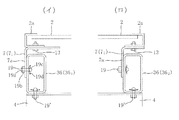
図7(イ)は図1〜図6で説明した実施例の場合であり、軽量溝形鋼による斜面上側のパネル受け材6(61)が開口を内向き(図7(イ)で右向き)にして配置され、軽量山形鋼による斜面上側の支持金具7(71)はその側面(下向きのフランジ7a)が斜面上側のパネル受け材61の斜面上側の側面(外側の面:ウエブ6a)に接し、側面同士がボルト9で接合された構成である。
図7(ロ)は軽量溝形鋼による斜面下側のパネル受け材6(62)が開口を外向き(図7(ロ)で右向き)にして配置され、軽量山形鋼による斜面下側の支持金具7(72)はその側面(下向きのフランジ7a)が斜面下側のパネル受け材62の斜面上側の側面(内側の面:ウエブ6a)に接し、側面同士がボルト9で接合された構成である。
As described above, in the present invention, the
As a relationship between the panel receiving material for that purpose and the support metal fittings or guide metal fittings fixed to the
FIG. 7 (a) is the case of the embodiment described with reference to FIGS. 1 to 6, and the panel receiving material 6 (6 1 ) on the upper side of the slope made of lightweight channel steel faces the opening inward (rightward in FIG. 7 (a)). ) to is arranged, lightweight angle iron slopes upper supporting
In FIG. 7 (b), the panel receiving material 6 (6 2 ) on the lower side of the slope made of lightweight channel steel is arranged with the opening facing outward (to the right in FIG. 7 (b)). bracket 7 (7 2) is a side (
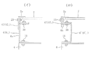
図8は支持金具を太陽光パネル2の枠材2aの側面にボルト23で固定する場合である。
図8(イ)は軽量溝形鋼による斜面上側のパネル受け材6(61)が開口を内向きにして配置され、太陽光パネル2の枠材2aの側面にボルト23で上部を固定されたフラットバー(平坦な鋼板)による斜面上側の支持金具27(271)の下部が、斜面上側のパネル受け材61の斜面上側の側面(外側の面:ウエブ6a)に接し、ボルト9で接合された構成である。
図8(ロ)は軽量溝形鋼による斜面上側のパネル受け材6’(61’)が開口を外向きにして配置され、太陽光パネル2の枠材2aの側面にボルト23で上部(一方のフランジ37a)を固定された軽量Z形鋼(横向きにした軽量Z形鋼)による斜面上側の支持金具37(371)の下部(他方のフランジ37b)が、斜面上側のパネル受け材61’の斜面下側の側面(開口と反対側の面:ウエブ6a’)に接し、ボルト9で接合された構成である。この場合、必要であれば枠材2aの下面と支持金具37のウエブとの間の隙間を埋める板を介在させるとよい。
図8(イ)、(ロ)の実施例では、太陽光パネル2の枠材2aの下面にボルトがないので、太陽光パネル2をパネル受け材6上でスライドさせる際、そのスライドが円滑に行なわれる。また、図8(ロ)の実施例では太陽光パネル2の枠材2aを支持金具37を介してパネル受け材6に載せたまま、支持金具37とパネル受け材6とをボルト接合できる。
FIG. 8 shows a case where the support metal fitting is fixed to the side surface of the
In FIG. 8 (a), a panel receiving member 6 (6 1 ) on the upper side of the slope made of lightweight channel steel is arranged with the opening facing inward, and the upper part is fixed to the side surface of the
In FIG. 8 (b), a
In the embodiment shown in FIGS. 8A and 8B, since there is no bolt on the lower surface of the
図9(イ)は角形鋼管による斜面上側のパネル受け材36(361)の斜面上側の側面(外側の面)に、軽量山形鋼による斜面上側の支持金具71の側面(下向きのフランジ7a)が接し、例えばワンサイドボルト19で接合された構成である。
図9(ロ)は角形鋼管による斜面下側のパネル受け材36(362)の斜面上側の側面(内側の面)に、軽量山形鋼による斜面下側の支持金具72の側面(下向きのフランジ7a)が接し、例えばワンサイドボルト19で接合された構成である。
なお、この実施例のようにパネル受け材36が角形鋼管の場合、図示のようにボルトとして片側の操作のみで締結できるワンサイドボルト19を使用することができる。図示例のワンサイドボルト19は、専用工具でボルト軸19aを掴みナット19bを捻じ込んでいくと、複数の縦スリットを入れたスリーブが先端の頭部19cで拡開して抜け止め部19dが形成され、2枚の板(軽量山形鋼7のフランジ7aと角形鋼管36の管壁と)が接合される構造である。
図示例では、パネル受け材36と架台支持材4との接合にもワンサイドボルト19’を使用している。
Figure 9 (b) is the slope upper side of the square tube slopes upper
9 (b) is the slope under side of the
When the
In the illustrated example, the one-
図10は角形鋼管による斜面上側のパネル受け材36(361)の斜面上側の側面(外側の面)に、太陽光パネル2の枠材2aの側面にボルト23で固定されたフラットバー(平坦な鋼板)による斜面上側の支持金具27(271)の下部が接し、ワンサイドボルト19で接合された構成である。
FIG. 10 shows a flat bar (flat) fixed to the side surface (outer surface) of the upper surface of the panel receiving member 36 (36 1 ) on the upper surface of the square steel pipe by
図11(イ)、(ロ)は、太陽光パネル2の斜面上側及び斜面下側の枠材2aの下面部をそれぞれ斜面上側又は斜面下側のパネル受け材6の上面部に直接ボルト39で固定する構造を採用する場合である。なお、図示例ではボルト39を捻じ込む枠材2a側のナット39aを予め枠材2aに溶接固定しているが、ワンサイドボルトを使用してもよい。
図11(イ)の実施例の場合、太陽光パネル2の斜面上側及び斜面下側の枠材2aの側面にそれぞれ、例えばフラットバー(平坦な鋼板)による斜面上側のガイド金具47(471)の上部を固定し、下部を図示例では開口部を内向きにした軽量溝形鋼による斜面上側のパネル受け材6(61)の側面(外側の側面(ウエブ6a))に当接させている。この場合、斜面上側のガイド金具47(471)は斜面上側のパネル受け材6(61)の斜面上側の側面(外側の面:ウエブ6a)に当接して、滑落防止の作用をする。
ガイド金具47は、パネル受け材6には固定されていないので、ガイド金具47付きの太陽光パネル2をパネル受け材6上に載せスライドさせて所定箇所に配する際にガイドの作用をし、かつ、前述の滑落防止の作用をするのみである。
図11(ロ)の実施例の場合、開口部を外向きにした軽量溝形鋼による斜面上側のパネル受け材6’(61’)の側面(フランジ6bの先端)に、フラットバーによる斜面上側のガイド金具47(471)の下部を当接させている。したがって、この実施例では、ガイド金具47はパネル受け材6’のフランジ6bの先端に当接してガイド作用及び滑落防止作用をする。
図11(イ)、(ロ)の実施例では、太陽光パネル2の枠材2aの下面にボルトがないので、太陽光パネル2をパネル受け材上でスライドさせる際、そのスライドが円滑に行なわれる。また、太陽光パネル2の枠材2aをパネル受け材に載せたまま、太陽光パネル2側をパネル受け材にボルト接合できる。
なお、上述した図7〜図11では、太陽光パネル2がパネル受け材6から滑落することを防止する斜面上側又は下側の一方のパネル受け材部分のみについて説明し、他方のパネル受け材部分についての説明は省略しているが、他方のパネル受け材部分は、太陽光パネル2をパネル受け材上で斜面横方向にスライドさせる際に太陽光パネル2が斜面上側に外れることも防ぐために、前記一方のパネル受け材部分と対称的な構造とするのが適切である。
11 (a) and 11 (b) show that the lower surface portion of the
In the case of the embodiment of FIG. 11 (a), the guide fitting 47 (47 1 ) on the upper side of the slope made of, for example, a flat bar (flat steel plate) is provided on the side surface of the
Since the guide fitting 47 is not fixed to the
In the case of the embodiment shown in FIG. 11 (b), a flat bar is provided on the side surface (tip of the
In the embodiment shown in FIGS. 11 (a) and 11 (b), since there is no bolt on the lower surface of the
In addition, in FIGS. 7-11 mentioned above, only the one panel receiving material part of the slope upper side or the lower side which prevents the
上記の太陽光パネル設置構造に用いるパネル受け材は、実施例の軽量溝形鋼や角形鋼管に限定されず、平坦な上面及び側面を有する適宜の断面形状の部材を使用することができる。この場合、側面については必ずしも長さ方向の全長に亘って平坦である必要はなく、支持金具7との関係で、断続的に平坦な側面を有する構造でもよい。
支持金具は、実施例の軽量山形鋼やフラットバーに限らず、適宜の断面形状の部材を用いることができる。
また、ガイド金具も、実施例のフラットバーに限らず、適宜の部材を用いることができる。
また、架台支持材を介在させる場合に、架台支持材として実施例の軽量溝形鋼に限らず、軽量H形鋼その他の断面形状の部材を用いることができる。
The panel receiving material used in the above solar panel installation structure is not limited to the light-duty grooved steel and square steel pipe of the embodiment, and a member having an appropriate cross-sectional shape having a flat upper surface and side surfaces can be used. In this case, the side surface does not necessarily need to be flat over the entire length in the length direction, and may have a structure having an intermittently flat side surface in relation to the
The support fitting is not limited to the lightweight angle steel and flat bar of the embodiment, and a member having an appropriate cross-sectional shape can be used.
Further, the guide fitting is not limited to the flat bar of the embodiment, and an appropriate member can be used.
Further, when the gantry support member is interposed, not only the lightweight grooved steel of the embodiment but also a lightweight H-section steel or other cross-sectional member can be used as the gantry support member.
上述の実施例では、1つの太陽光パネル設置架台5に斜面横方向に並ぶ3つの太陽光パネル2を設置しているが、2つであってもよいし、またパネル受け材6を長くすることで4つ以上の太陽光パネル2を設置することができる。
また、実施例の太陽光パネル設置構造1は、架台支持材4に斜面傾斜方向の上側と下側との2つの太陽光パネル設置架台5を設置しているが、1つであってもよいし、また、架台支持材4を長くすることで、3つ以上の太陽光パネル設置架台5を設置することもできる。ただし、斜面傾斜方向の2つの太陽光パネル設置架台5どうしの間隔は、作業者がその間に容易に入って作業できる間隔とする。
また、実施例では、杭3の高さが等しく架台支持材4及び太陽光パネル設置架台5が斜面と平行であり、太陽光パネル2が斜面と平行に設置されているが、太陽光パネル設置架台5は斜面の傾斜角度に合わせる必要がなく、杭3の高さを調整するなどして設置場所に合わせた適切な傾斜角度に設定するとよい。
また、実施例では、基礎部としてラセン状の杭3を採用しているが、これに限らず種々の杭を採用することができ、また、杭に限らず、種々のタイプの基礎を採用することができる。
また、基礎部として柱状基礎である杭を採用する場合、実施例では杭を斜面に垂直に設置しているが、鉛直に設置してもよい。
また、実施例では太陽光パネル設置架台5を架台支持材4を介して基礎部3に設置しているが、太陽光パネル設置架台5を直接基礎部に設置(すなわち、パネル受け材6を基礎に直接設置)することも可能である。
In the above-described embodiment, three
Moreover, although the solar
Moreover, in the Example, although the height of the
Moreover, in the Example, although the
Moreover, when employ | adopting the pile which is a columnar foundation as a foundation part, although the pile is installed perpendicularly | vertically to the slope in the Example, you may install vertically.
Moreover, although the solar
1 太陽光パネル設置構造
2 太陽光パネル
2a 枠材
2b 太陽電池モジュール
3 杭(基礎部)
3b 円板
3c ボルト
3d ナット
4 架台支持材
5 太陽光パネル設置架台
6、6’ パネル受け材
61、61’ 斜面上側のパネル受け材
62 斜面下側のパネル受け材
6a ウエブ
6b フランジ
7 支持金具
71 斜面上側の支持金具
72 斜面下側の支持金具
7a (下方に延びる)フランジ
7b 他方のフランジ
9、11、13、17 ボルト
S 斜面
DESCRIPTION OF
Claims (5)
斜面に設けられた基礎部と、この基礎部上に設けられて斜面の傾斜方向と直交する横方向に隣り合うように配される複数の太陽光パネルを設置する太陽光パネル設置架台とを備え、
前記太陽光パネル設置架台は、斜面の傾斜方向と直交する横方向に延長する態様で斜面上側と斜面下側とに間隔をあけて互いに平行に配されて前記基礎部上に直接又は架台支持材を介して取り付けられる、平坦な上面及び側面を有する棒状のパネル受け材と、前記太陽光パネルの斜面上側及び斜面下側の枠材にそれぞれ上部が固定される支持金具とを備え、斜面上側及び斜面下側の前記パネル受け材は、斜面上側及び斜面下側の前記支持金具の下部をそれぞれ固定することで前記複数の太陽光パネルを載架し、
前記斜面上側の支持金具及び前記斜面下側の支持金具はそれぞれ、その下部が前記斜面上側のパネル受け材又は前記斜面下側のパネル受け材の斜面傾斜方向の側面に対し側面から接するように配されてそれぞれパネル受け材にボルトで固定されるとともに、前記斜面上側又は斜面下側の少なくとも一方の支持金具はパネル受け材の斜面上側の側面に接していることを特徴とする太陽光パネル設置構造。 A solar panel installation structure for installing a solar panel on a slope,
A foundation provided on the slope, and a solar panel installation base for installing a plurality of solar panels arranged on the foundation and arranged adjacent to each other in a lateral direction perpendicular to the inclination direction of the slope. ,
The solar panel installation base is arranged in parallel to each other with an interval between the upper side of the slope and the lower side of the slope in a manner extending in a lateral direction orthogonal to the slope direction of the slope, and is directly or on the base support member. A bar-shaped panel receiving material having a flat upper surface and side surfaces, and support brackets whose upper portions are respectively fixed to the upper and lower slope frame members of the solar panel, The panel receiving material on the lower side of the slope mounts the plurality of solar panels by fixing the lower part of the support bracket on the upper side of the slope and the lower side of the slope,
The upper support bracket and the lower support bracket are arranged so that their lower portions are in contact with the side surfaces of the slope upper panel receiving material or the lower panel receiving material from the side surface. The solar panel installation structure, wherein each of the support brackets on the upper side of the slope or the lower side of the slope is in contact with the side surface of the upper side of the slope of the panel receiver. .
斜面に設けられた基礎部と、この基礎部上に設けられて斜面の傾斜方向と直交する横方向に隣り合うように配される複数の太陽光パネルを設置する太陽光パネル設置架台とを備え、
前記太陽光パネル設置架台は、斜面の傾斜方向と直交する横方向に延長する態様で斜面上側と斜面下側とに間隔をあけて互いに平行に配されて前記基礎部上に直接又は架台支持材を介して取り付けられる、平坦な上面及び側面を有する棒状のパネル受け材と、前記太陽光パネルの斜面上側及び斜面下側の枠材にそれぞれ上部が固定されるガイド金具とを備え、斜面上側及び斜面下側の前記パネル受け材は、その上面に載せた前記複数の太陽光パネルの斜面上側及び斜面下側の枠材の下面部をそれぞれボルトで固定することで前記複数の太陽光パネルを載架し、
前記斜面上側のガイド金具及び前記斜面下側のガイド金具はそれぞれ、その下部が前記斜面上側のパネル受け材又は前記斜面下側のパネル受け材の斜面傾斜方向の側面に対し側面から接するように配されるとともに、前記斜面上側又は斜面下側の少なくとも一方のガイド金具はパネル受け材の斜面上側の側面に接していることを特徴とする太陽光パネル設置構造。 A solar panel installation structure for installing a solar panel on a slope,
A foundation provided on the slope, and a solar panel installation base for installing a plurality of solar panels arranged on the foundation and arranged adjacent to each other in a lateral direction perpendicular to the inclination direction of the slope. ,
The solar panel installation base is arranged in parallel to each other with an interval between the upper side of the slope and the lower side of the slope in a manner extending in a lateral direction orthogonal to the slope direction of the slope, and is directly or on the base support member. A bar-shaped panel receiving material having a flat upper surface and side surfaces, and guide fittings whose upper portions are respectively fixed to the upper and lower slope frame members of the solar panel, The panel receiving material on the lower side of the slope mounts the plurality of solar panels by fixing the upper surface of the slope of the plurality of solar panels and the lower surface of the frame material on the lower side of the slope with bolts, respectively. Hanging,
The guide fittings on the upper side of the slope and the guide fittings on the lower side of the slope are arranged so that the lower portions thereof are in contact with the side surfaces in the slope inclination direction of the panel receiving material on the upper side of the slope or the panel receiving material on the lower side of the slope. The solar panel installation structure is characterized in that at least one guide metal fitting on the upper side or lower side of the slope is in contact with the side surface on the upper side of the slope of the panel receiving member.
前記架台支持材は、前記基礎部上に固定されて斜面傾斜方向をなす互いに平行な2本以上の棒状部材であり、この架台支持材上に前記パネル受け材の下面が固定されていることを特徴とする請求項1〜3のいずれか1項に記載の太陽光パネル設置構造。 When the panel receiving material is attached to the foundation part via a gantry support material,
The gantry support material is two or more bar-shaped members that are fixed on the base portion and have an inclined slope direction and are parallel to each other, and the lower surface of the panel receiving material is fixed on the gantry support material. The solar panel installation structure of any one of Claims 1-3 characterized by the above-mentioned.
前記基礎部上に直接又は架台支持材を介して前記一対のパネル受け材を、その一対が斜面の傾斜方向と直交する横方向に延長する態様で斜面上側と斜面下側とに間隔をあけて互いに平行に取り付け、
前記支持金具又はガイド金具を固定した複数の太陽光パネルを順次、斜面上側及び斜面下側の支持金具又はガイド金具の下部がパネル受け材の斜面傾斜方向の側面に接するように配して斜面傾斜方向上下のパネル受け材上に載せ斜面横方向にスライドさせて、斜面傾斜方向上下のパネル受け材間に配置し、次いで、支持金具とパネル受け材とを、若しくは太陽光パネルの枠材とパネル受け材とをボルトにより固定することを特徴とする太陽光パネル設置施工方法。 With the solar panel installation structure according to any one of claims 1 to 4, a plurality of solar panels arranged to be adjacent to each other in a lateral direction orthogonal to the inclination direction of the slope are installed on the foundation provided on the slope. A solar panel installation method,
The pair of panel receiving members are arranged on the base portion directly or via a gantry support member, with the pair extending in a lateral direction perpendicular to the inclined direction of the inclined surface, with an interval between the upper side of the inclined surface and the lower side of the inclined surface. Install parallel to each other,
A plurality of solar panels to which the support metal fittings or guide metal fittings are fixed are arranged so that the lower part of the support metal fittings or the guide metal fittings on the upper slope side and the lower side of the slope are in contact with the side surfaces in the slope inclination direction of the panel receiving material. Place it on the upper and lower panel receiving materials and slide it laterally on the slope, and place it between the upper and lower panel receiving materials in the inclined direction of the slope, and then attach the support bracket and the panel receiving material, or the frame material and panel of the solar panel A solar panel installation method characterized by fixing the receiving material with bolts.
Priority Applications (1)
| Application Number | Priority Date | Filing Date | Title |
|---|---|---|---|
| JP2011226474A JP5844112B2 (en) | 2011-10-14 | 2011-10-14 | Solar panel installation structure and solar panel installation construction method |
Applications Claiming Priority (1)
| Application Number | Priority Date | Filing Date | Title |
|---|---|---|---|
| JP2011226474A JP5844112B2 (en) | 2011-10-14 | 2011-10-14 | Solar panel installation structure and solar panel installation construction method |
Publications (2)
| Publication Number | Publication Date |
|---|---|
| JP2013089658A JP2013089658A (en) | 2013-05-13 |
| JP5844112B2 true JP5844112B2 (en) | 2016-01-13 |
Family
ID=48533305
Family Applications (1)
| Application Number | Title | Priority Date | Filing Date |
|---|---|---|---|
| JP2011226474A Expired - Fee Related JP5844112B2 (en) | 2011-10-14 | 2011-10-14 | Solar panel installation structure and solar panel installation construction method |
Country Status (1)
| Country | Link |
|---|---|
| JP (1) | JP5844112B2 (en) |
Families Citing this family (1)
| Publication number | Priority date | Publication date | Assignee | Title |
|---|---|---|---|---|
| JP2018186636A (en) * | 2017-04-25 | 2018-11-22 | 日新製鋼株式会社 | Solar cell panel installation frame and manufacturing method thereof |
-
2011
- 2011-10-14 JP JP2011226474A patent/JP5844112B2/en not_active Expired - Fee Related
Also Published As
| Publication number | Publication date |
|---|---|
| JP2013089658A (en) | 2013-05-13 |
Similar Documents
| Publication | Publication Date | Title |
|---|---|---|
| US9660569B2 (en) | Solar array support structure, mounting rail and method of installation thereof | |
| JP4562793B2 (en) | Structure installation stand and solar cell system | |
| US8468755B2 (en) | Solar array support structure | |
| JP6166908B2 (en) | Support column for solar cell panel support | |
| KR20170044538A (en) | System for Supporting Solar Panel Array | |
| JP2016220326A (en) | Cradle for solar battery module and photovoltaic power generation device | |
| JP5956214B2 (en) | Foundation structure for the solar cell module support | |
| JP2014163073A (en) | Support frame mounting fitting, and photovoltaic power generation panel installation system | |
| JP6412342B2 (en) | Method for constructing support frame for planar article | |
| JP6441041B2 (en) | Solar panel mount | |
| JP5844112B2 (en) | Solar panel installation structure and solar panel installation construction method | |
| JP6746861B2 (en) | Screw pile joint member and pile foundation | |
| JP5622709B2 (en) | Supporting frame structure for photovoltaic panel frame | |
| JP5938826B2 (en) | Solar panel installation structure and solar panel installation construction method | |
| JP2014088708A (en) | Mounting rack for photovoltaic generation module and photovoltaic generation device | |
| JP3181778U (en) | Photovoltaic panel support stand | |
| JP2013243201A (en) | Solar panel unit, solar panel device, and installation method of solar panel | |
| JP5936934B2 (en) | Panel holding structure | |
| JP6667280B2 (en) | Mounting structure and method of mounting | |
| JP3181744U (en) | Solar panel mounting base | |
| CN113193814A (en) | Photovoltaic power generation system, photovoltaic power generation device and photovoltaic array supporting device | |
| JP2015158116A (en) | Photovoltaic power generation panel frame | |
| JP2015122944A (en) | Frame for installing photovoltaic power generation module | |
| JP2015098725A (en) | Photovoltaic power generation panel stand and installation method for the same | |
| JP6242728B2 (en) | Solar panel mount |
Legal Events
| Date | Code | Title | Description |
|---|---|---|---|
| A621 | Written request for application examination |
Free format text: JAPANESE INTERMEDIATE CODE: A621 Effective date: 20140822 |
|
| A131 | Notification of reasons for refusal |
Free format text: JAPANESE INTERMEDIATE CODE: A131 Effective date: 20150707 |
|
| A521 | Written amendment |
Free format text: JAPANESE INTERMEDIATE CODE: A523 Effective date: 20150715 |
|
| TRDD | Decision of grant or rejection written | ||
| A01 | Written decision to grant a patent or to grant a registration (utility model) |
Free format text: JAPANESE INTERMEDIATE CODE: A01 Effective date: 20151117 |
|
| A61 | First payment of annual fees (during grant procedure) |
Free format text: JAPANESE INTERMEDIATE CODE: A61 Effective date: 20151118 |
|
| R150 | Certificate of patent or registration of utility model |
Ref document number: 5844112 Country of ref document: JP Free format text: JAPANESE INTERMEDIATE CODE: R150 |
|
| LAPS | Cancellation because of no payment of annual fees |