JP5841842B2 - Reduction of wrinkles in uncured composite laminates - Google Patents
Reduction of wrinkles in uncured composite laminates Download PDFInfo
- Publication number
- JP5841842B2 JP5841842B2 JP2011529339A JP2011529339A JP5841842B2 JP 5841842 B2 JP5841842 B2 JP 5841842B2 JP 2011529339 A JP2011529339 A JP 2011529339A JP 2011529339 A JP2011529339 A JP 2011529339A JP 5841842 B2 JP5841842 B2 JP 5841842B2
- Authority
- JP
- Japan
- Prior art keywords
- heel
- head
- laminate
- layer
- wrinkles
- Prior art date
- Legal status (The legal status is an assumption and is not a legal conclusion. Google has not performed a legal analysis and makes no representation as to the accuracy of the status listed.)
- Active
Links
- 230000037303 wrinkles Effects 0.000 title claims description 44
- 239000002131 composite material Substances 0.000 title description 10
- 230000009467 reduction Effects 0.000 title description 4
- 238000000034 method Methods 0.000 claims description 57
- 238000003825 pressing Methods 0.000 claims description 19
- 229920005989 resin Polymers 0.000 claims description 16
- 239000011347 resin Substances 0.000 claims description 16
- 239000000835 fiber Substances 0.000 claims description 8
- 230000001681 protective effect Effects 0.000 claims description 7
- 238000010438 heat treatment Methods 0.000 claims description 5
- 229920000049 Carbon (fiber) Polymers 0.000 claims description 2
- 239000004917 carbon fiber Substances 0.000 claims description 2
- 238000010030 laminating Methods 0.000 claims description 2
- 230000003068 static effect Effects 0.000 claims description 2
- 230000003534 oscillatory effect Effects 0.000 claims 2
- VNWKTOKETHGBQD-UHFFFAOYSA-N methane Chemical compound C VNWKTOKETHGBQD-UHFFFAOYSA-N 0.000 claims 1
- 238000000465 moulding Methods 0.000 claims 1
- 239000010410 layer Substances 0.000 description 35
- 239000012783 reinforcing fiber Substances 0.000 description 11
- 238000004519 manufacturing process Methods 0.000 description 9
- 230000008569 process Effects 0.000 description 6
- 238000010586 diagram Methods 0.000 description 5
- 238000012545 processing Methods 0.000 description 5
- 238000011946 reduction process Methods 0.000 description 5
- 239000004071 soot Substances 0.000 description 5
- 238000012423 maintenance Methods 0.000 description 4
- 230000037331 wrinkle reduction Effects 0.000 description 4
- 239000003733 fiber-reinforced composite Substances 0.000 description 3
- 238000003475 lamination Methods 0.000 description 3
- 239000000463 material Substances 0.000 description 3
- 239000011159 matrix material Substances 0.000 description 3
- 239000011230 binding agent Substances 0.000 description 2
- 230000005284 excitation Effects 0.000 description 2
- 239000004809 Teflon Substances 0.000 description 1
- 229920006362 Teflon® Polymers 0.000 description 1
- 238000013475 authorization Methods 0.000 description 1
- 230000008859 change Effects 0.000 description 1
- 238000013461 design Methods 0.000 description 1
- 230000007613 environmental effect Effects 0.000 description 1
- 239000003822 epoxy resin Substances 0.000 description 1
- 239000004744 fabric Substances 0.000 description 1
- 239000003365 glass fiber Substances 0.000 description 1
- 230000006872 improvement Effects 0.000 description 1
- 230000010354 integration Effects 0.000 description 1
- 229920000647 polyepoxide Polymers 0.000 description 1
- 238000009419 refurbishment Methods 0.000 description 1
- 239000002356 single layer Substances 0.000 description 1
- 239000003351 stiffener Substances 0.000 description 1
- 230000007704 transition Effects 0.000 description 1
Images


Classifications
-
- B—PERFORMING OPERATIONS; TRANSPORTING
- B29—WORKING OF PLASTICS; WORKING OF SUBSTANCES IN A PLASTIC STATE IN GENERAL
- B29C—SHAPING OR JOINING OF PLASTICS; SHAPING OF MATERIAL IN A PLASTIC STATE, NOT OTHERWISE PROVIDED FOR; AFTER-TREATMENT OF THE SHAPED PRODUCTS, e.g. REPAIRING
- B29C70/00—Shaping composites, i.e. plastics material comprising reinforcements, fillers or preformed parts, e.g. inserts
- B29C70/04—Shaping composites, i.e. plastics material comprising reinforcements, fillers or preformed parts, e.g. inserts comprising reinforcements only, e.g. self-reinforcing plastics
- B29C70/28—Shaping operations therefor
- B29C70/30—Shaping by lay-up, i.e. applying fibres, tape or broadsheet on a mould, former or core; Shaping by spray-up, i.e. spraying of fibres on a mould, former or core
-
- B—PERFORMING OPERATIONS; TRANSPORTING
- B29—WORKING OF PLASTICS; WORKING OF SUBSTANCES IN A PLASTIC STATE IN GENERAL
- B29C—SHAPING OR JOINING OF PLASTICS; SHAPING OF MATERIAL IN A PLASTIC STATE, NOT OTHERWISE PROVIDED FOR; AFTER-TREATMENT OF THE SHAPED PRODUCTS, e.g. REPAIRING
- B29C70/00—Shaping composites, i.e. plastics material comprising reinforcements, fillers or preformed parts, e.g. inserts
- B29C70/04—Shaping composites, i.e. plastics material comprising reinforcements, fillers or preformed parts, e.g. inserts comprising reinforcements only, e.g. self-reinforcing plastics
- B29C70/28—Shaping operations therefor
- B29C70/54—Component parts, details or accessories; Auxiliary operations, e.g. feeding or storage of prepregs or SMC after impregnation or during ageing
- B29C70/543—Fixing the position or configuration of fibrous reinforcements before or during moulding
-
- C—CHEMISTRY; METALLURGY
- C08—ORGANIC MACROMOLECULAR COMPOUNDS; THEIR PREPARATION OR CHEMICAL WORKING-UP; COMPOSITIONS BASED THEREON
- C08J—WORKING-UP; GENERAL PROCESSES OF COMPOUNDING; AFTER-TREATMENT NOT COVERED BY SUBCLASSES C08B, C08C, C08F, C08G or C08H
- C08J5/00—Manufacture of articles or shaped materials containing macromolecular substances
- C08J5/24—Impregnating materials with prepolymers which can be polymerised in situ, e.g. manufacture of prepregs
- C08J5/241—Impregnating materials with prepolymers which can be polymerised in situ, e.g. manufacture of prepregs using inorganic fibres
- C08J5/243—Impregnating materials with prepolymers which can be polymerised in situ, e.g. manufacture of prepregs using inorganic fibres using carbon fibres
-
- C—CHEMISTRY; METALLURGY
- C08—ORGANIC MACROMOLECULAR COMPOUNDS; THEIR PREPARATION OR CHEMICAL WORKING-UP; COMPOSITIONS BASED THEREON
- C08J—WORKING-UP; GENERAL PROCESSES OF COMPOUNDING; AFTER-TREATMENT NOT COVERED BY SUBCLASSES C08B, C08C, C08F, C08G or C08H
- C08J5/00—Manufacture of articles or shaped materials containing macromolecular substances
- C08J5/24—Impregnating materials with prepolymers which can be polymerised in situ, e.g. manufacture of prepregs
- C08J5/248—Impregnating materials with prepolymers which can be polymerised in situ, e.g. manufacture of prepregs using pre-treated fibres
-
- B—PERFORMING OPERATIONS; TRANSPORTING
- B29—WORKING OF PLASTICS; WORKING OF SUBSTANCES IN A PLASTIC STATE IN GENERAL
- B29C—SHAPING OR JOINING OF PLASTICS; SHAPING OF MATERIAL IN A PLASTIC STATE, NOT OTHERWISE PROVIDED FOR; AFTER-TREATMENT OF THE SHAPED PRODUCTS, e.g. REPAIRING
- B29C35/00—Heating, cooling or curing, e.g. crosslinking or vulcanising; Apparatus therefor
- B29C35/02—Heating or curing, e.g. crosslinking or vulcanizing during moulding, e.g. in a mould
- B29C35/0261—Heating or curing, e.g. crosslinking or vulcanizing during moulding, e.g. in a mould using ultrasonic or sonic vibrations
-
- B—PERFORMING OPERATIONS; TRANSPORTING
- B29—WORKING OF PLASTICS; WORKING OF SUBSTANCES IN A PLASTIC STATE IN GENERAL
- B29C—SHAPING OR JOINING OF PLASTICS; SHAPING OF MATERIAL IN A PLASTIC STATE, NOT OTHERWISE PROVIDED FOR; AFTER-TREATMENT OF THE SHAPED PRODUCTS, e.g. REPAIRING
- B29C35/00—Heating, cooling or curing, e.g. crosslinking or vulcanising; Apparatus therefor
- B29C35/02—Heating or curing, e.g. crosslinking or vulcanizing during moulding, e.g. in a mould
- B29C35/0266—Local curing
Landscapes
- Chemical & Material Sciences (AREA)
- Engineering & Computer Science (AREA)
- Materials Engineering (AREA)
- Composite Materials (AREA)
- Mechanical Engineering (AREA)
- Medicinal Chemistry (AREA)
- Health & Medical Sciences (AREA)
- Chemical Kinetics & Catalysis (AREA)
- Manufacturing & Machinery (AREA)
- Polymers & Plastics (AREA)
- Organic Chemistry (AREA)
- Textile Engineering (AREA)
- Inorganic Chemistry (AREA)
- Moulding By Coating Moulds (AREA)
- Processing And Handling Of Plastics And Other Materials For Molding In General (AREA)
- Shaping Of Tube Ends By Bending Or Straightening (AREA)
- Heating, Cooling, Or Curing Plastics Or The Like In General (AREA)
- Casting Or Compression Moulding Of Plastics Or The Like (AREA)
- Reinforced Plastic Materials (AREA)
Description
本発明は概して複合積層体の加工に関し、さらに具体的には未硬化の積層体の皺を低減する方法に関するものである。 The present invention relates generally to the processing of composite laminates, and more specifically to a method for reducing wrinkles in an uncured laminate.
複数層の未硬化プリプレグを積層して、複合積層体を形成するプロセスの間に、しばしば一又は複数の層に皺が形成される場合がある。皺は非限定的に、積層プロセス中に変形した層、及び/又は、未硬化樹脂の粘着性によって発生する強化繊維間の比較的強い摩擦によるものであり得る。皺により硬化積層体の空隙又は切れ目が起きる可能性があるため望ましくない。 During the process of laminating multiple layers of uncured prepreg to form a composite laminate, wrinkles can often form in one or more layers. Wrinkles can be due to, but not limited to, the relatively deformed friction between the layers deformed during the lamination process and / or the reinforcing fibers generated by the tackiness of the uncured resin. It is not desirable because voids or breaks in the cured laminate may occur due to wrinkles.
過去においては、未硬化の積層体に起こる皺は、皺を伸ばしやすい手動ツールを使用して皺を手で「こする」ことによって、皺に熱及び圧力を加えて取り除くことができた。皺を取り除くこの先行技術は時間がかかり、ある場合には効果がないこともある。 In the past, wrinkles that occur in uncured laminates could be removed by applying heat and pressure to the wrinkles by manually “rubbing” the wrinkles using a manual tool that facilitates stretching the wrinkles. This prior art of removing wrinkles is time consuming and in some cases ineffective.
したがって、迅速で効果的であり、皺の改善プロセス中に強化繊維を実質的に変えることがない、未硬化の繊維強化樹脂の積層体から皺を低減する又は取り除く方法が必要である。 Accordingly, there is a need for a method of reducing or removing wrinkles from a laminate of uncured fiber reinforced resin that is fast and effective and does not substantially change the reinforcing fibers during the wrinkle improvement process.
積層プロセス中に未硬化積層体に形成される皺は、高周波数、低振幅振動と圧力を組合せて皺に加えることによって実質的に低減する又は取り除くことができる。皺低減プロセスは効果的であり、強化繊維の望ましくない変化又は乱れが最小限に抑えられる。未硬化積層体の皺の低減は、手動でこする先行技術と比べて短い時間で行うことができ、これによりこの方法を高速製造用途に用いることができ、皺の低減プロセスを行うために必要な特別な機器も最小限に抑えることができる。 Soot formed in the uncured laminate during the lamination process can be substantially reduced or eliminated by applying a combination of high frequency, low amplitude vibration and pressure to the soot. The wrinkle reduction process is effective and minimizes undesirable changes or perturbations in the reinforcing fibers. The reduction of wrinkles in the uncured laminate can be done in a shorter time compared to prior art rubbing manually, which allows this method to be used in high speed manufacturing applications and is necessary to perform the wrinkle reduction process Special equipment can also be kept to a minimum.
開示の方法は、層の遷移領域の上に形成されたハットスティフナー、C及びZフレーム等のドレープ形成部品の内側脚部、及び航空機用のI形状の翼ストリンガーの特定領域の場合のように、積層体の層が互いにくっつきやすい所の皺を低減する又は除去するのに特に効果的である。 The disclosed method, as in the case of a hat stiffener formed on the transition region of the layer, the inner leg of a draping part such as a C and Z frame, and a specific region of an I-shaped wing stringer for an aircraft, It is particularly effective in reducing or eliminating wrinkles where the layers of the laminate tend to stick to each other.
ある開示の方法の実施形態によれば、繊維強化プリプレグ樹脂層の皺を低減する方法は、皺に振動を与えることを含む。トランスデューサのヘッドを層と接触させて、トランスデューサを励起して振動を起こさせ、トランスデューサのヘッドを皺の上で動かすことによって、皺に振動を与えることができる。振動は高周波数及び低振幅のものであることが好ましい。トランスデューサのヘッドによって強化繊維が変形又は変化しないように、保護シートをトランスデューサのヘッドと層の間に配置することができる。皺の低減を促進するために、トランスデューサのヘッドを介して皺に圧力を加えることができる。 According to certain disclosed method embodiments, a method of reducing wrinkles in a fiber reinforced prepreg resin layer includes imparting vibrations to the wrinkles. The transducer head can be vibrated by bringing the transducer head into contact with the layer, exciting the transducer to cause vibration, and moving the transducer head over the kite. The vibration is preferably of high frequency and low amplitude. A protective sheet can be placed between the transducer head and the layer so that the reinforcing fiber is not deformed or changed by the transducer head. To promote wrinkle reduction, pressure can be applied to the wrinkle through the head of the transducer.
別の方法の実施形態では、未硬化複合積層体の皺を低減する方法は:ヘッドを使用して皺のある領域の積層体に圧力を印加し;積層体に圧力をかけながら、ヘッドを皺の上で動かし;ヘッドで積層体に圧力をかけながら、ヘッドを振動させることによって皺に振動を加えることを含む。積層体の強化繊維を保護するために、ヘッドと皺の領域の積層体の間にシートを配置することができ、シートにヘッドを押し付けることによって、ヘッドによって積層体に圧力をかけることができる。ヘッドは高周波数、低振幅の信号を使用して励起することができる。 In another method embodiment, a method for reducing wrinkles in an uncured composite laminate includes: applying pressure to a stack in a wrinkled region using a head; Including applying vibration to the heel by vibrating the head while applying pressure to the laminate with the head. In order to protect the reinforcing fibers of the laminate, a sheet can be placed between the laminate in the area of the head and the ridge, and pressure can be applied to the laminate by the head by pressing the head against the sheet. The head can be excited using a high frequency, low amplitude signal.
さらなる方法の実施形態によれば、複合航空機サブアセンブリを加工する方法は:複数層の繊維強化複合積層体を形成し、ここで複数層のうちの少なくとも1つの層が皺を含み;トランスデューサのヘッドを使用して皺の領域の少なくとも1つの層に圧力を印加して、トランスデューサのヘッドを層の上で動かすことによって皺を低減し;トランスデューサのヘッドで少なくとも1つの層に圧力をかけながら、トランスデューサのヘッドを励起して振動させ;積層体を成形し;そして積層体を硬化させることを含む。本方法はさらに、積層体の少なくとも一部の上に平坦なシートを配置して平坦なシートで皺をカバーし、シートにトランスデューサのヘッドを押し付けることによって、少なくとも1つの層に圧力を印加し;次に、皺が低減された後に、積層体からシートを取り外すことを含むことができる。 According to a further method embodiment, a method of processing a composite aircraft subassembly includes: forming a multiple layer fiber reinforced composite laminate, wherein at least one of the multiple layers includes a ridge; To reduce pressure by applying pressure to at least one layer in the heel region and moving the transducer head over the layer; while applying pressure to the at least one layer with the transducer head, Exciting and vibrating; forming the laminate; and curing the laminate. The method further applies pressure to at least one layer by placing a flat sheet over at least a portion of the laminate, covering the ridge with the flat sheet, and pressing a transducer head against the sheet; Next, it can include removing the sheet from the laminate after wrinkles have been reduced.
10.未硬化の複合積層体の皺を低減する方法であって:
ヘッドを使用して皺の領域の積層体に圧力を印加し;
積層体に圧力を掛けながら、皺の上でヘッドを動かし;
ヘッドで積層体に圧力を掛けながら、ヘッドを振動させることによって皺に振動を印加する
ことを含む方法。
11.皺の領域の積層体の上にシートを配置することによって積層体を保護することをさらに含み、
シートにヘッドを押し付けることによって、ヘッドによって積層体に圧力が印加される、
請求項10に記載の方法。
10. A method for reducing wrinkles in an uncured composite laminate comprising:
Applying pressure to the stack in the heel region using a head;
Move the head on the heel while applying pressure to the laminate;
Applying a vibration to the bag by vibrating the head while applying pressure to the laminate with the head.
11. Further comprising protecting the laminate by placing a sheet over the laminate in the heel region;
By pressing the head against the sheet, pressure is applied to the laminate by the head,
The method of claim 10.
12.ヘッドを振動させることが、高周波信号でヘッドを励起することを含む、請求項10に記載の方法。
13.ヘッドを励起することが、約15000〜70000Hzの周波数を有する信号でヘッドを励起することを含む、請求項12に記載の方法。
14.ヘッドを振動させることが、低振幅信号でヘッドを励起することを含む、請求項10に記載の方法。
12 The method of claim 10, wherein oscillating the head comprises exciting the head with a high frequency signal.
13. The method of claim 12, wherein exciting the head includes exciting the head with a signal having a frequency of about 15000-70000 Hz.
14 The method of claim 10, wherein vibrating the head comprises exciting the head with a low amplitude signal.
15.低振幅信号でヘッドを励起することが、約0.0005〜0.005インチの振幅を有する信号をヘッドへ送ることを含む、請求項14に記載の方法。
16.シートが、ヘッドを押し付ける実質的に平坦な保護面を含む、請求項11に記載の方法。
17.少なくとも皺の領域の層を加熱することをさらに含む、請求項10に記載の方法。
15. 15. The method of claim 14, wherein exciting the head with a low amplitude signal includes sending a signal having an amplitude of about 0.0005 to 0.005 inches to the head.
16. The method of claim 11, wherein the sheet includes a substantially flat protective surface that presses against the head.
17. 11. The method of claim 10, further comprising heating the layer in at least the heel region.
18.複合航空機サブアセンブリを加工する方法であって:
複数層の繊維強化複合積層体を形成し、複数層のうちの少なくとも1つの層が皺を含み;
皺を、
トランスデューサのヘッドを使用して、皺の領域の少なくとも1つの層に圧力を印加し、
トランスデューサのヘッドを層の上で動かし、
トランスデューサのヘッドが少なくとも1つの層に圧力をかけている間に、トランスデューサのヘッドを励起して振動させる
ことによって低減し;
積層体を成形し;
積層体を硬化させる
ことを含む方法。
18. A method of processing a composite aircraft subassembly comprising:
Forming a multi-layer fiber reinforced composite laminate, wherein at least one of the plurality of layers includes ridges;
皺
Using the transducer head, apply pressure to at least one layer in the heel region;
Move the transducer head over the layer,
Reduced by exciting and vibrating the transducer head while the transducer head is applying pressure to at least one layer;
Forming a laminate;
Curing the laminate.
19.さらに:
積層体の少なくとも一部の上に平坦なシートを配置することによって、平坦なシートで皺をカバーし;
皺が低減された後で、積層体からシートを取り外す
ことを含み、
トランスデューサのヘッドを使用して少なくとも1つの層に圧力を印加することが、トランスデューサのヘッドをシートに押し付けることを含む、
請求項18に記載の方法。
20.トランスデューサのヘッドを励起して振動させることが、トランスデューサのヘッドに高周波励起信号を送ることを含む、請求項18に記載の方法。
19. further:
Covering the ridge with a flat sheet by placing a flat sheet on at least a portion of the laminate;
Removing the sheet from the laminate after wrinkles have been reduced,
Applying pressure to the at least one layer using the transducer head includes pressing the transducer head against the sheet;
The method of claim 18.
20. The method of claim 18, wherein exciting and vibrating the transducer head includes sending a high frequency excitation signal to the transducer head.
21.高周波励起信号を送ることが、約15000〜70000Hzの周波数を有する信号を送ることを含む、請求項20に記載の方法。
22.信号が低振幅を有する、請求項21に記載の方法。
23.信号の振幅が約0.0005〜0.005インチである、請求項22に記載の方法。
24.皺の領域の少なくとも1つの層を加熱する
ことをさらに含む、請求項18に記載の方法。
21. 21. The method of
22. The method of claim 21, wherein the signal has a low amplitude.
23. 23. The method of
24. The method of claim 18, further comprising heating at least one layer of the heel region.
25.複合航空機サブアセンブリを加工する方法であって:
複数層の繊維強化複合積層体を形成し、積層体が皺を含み;
皺を、
実質的に平坦なシートを積層体の上に配置して皺をカバーし、
トランスデューサのヘッドをシートに接触させ;
トランスデューサのヘッドを皺の領域のシートに押し付けることによって、皺に圧力を印加し、
トランスデューサのヘッドをシートに押し付けながら、トランスデューサのヘッドを積層体の上で動かし、
少なくとも皺の領域の積層体を加熱し、
トランスデューサのヘッドをシートに押し付けながら、高周波、低振幅信号でトランスデューサのヘッドを励起して振動させる
ことによって低減し;
皺が低減された後で、シートをとりはずし;
積層体を成形し;
積層体を硬化させる
ことを含む方法。
25. A method of processing a composite aircraft subassembly comprising:
Forming a multi-layer fiber reinforced composite laminate, wherein the laminate comprises wrinkles;
皺
A substantially flat sheet is placed over the laminate to cover the folds,
Bringing the transducer head into contact with the sheet;
Apply pressure on the heel by pressing the transducer head against the sheet in the heel area,
While pressing the transducer head against the sheet, move the transducer head over the stack,
Heating the laminate in at least the heel region,
Reduced by exciting and vibrating the transducer head with a high frequency, low amplitude signal while pressing the transducer head against the sheet;
After the wrinkle is reduced, remove the sheet;
Forming a laminate;
Curing the laminate.
開示された実施形態の他の機構、利点及び長所は、添付の図面及び添付の請求項に従って下記の実施形態の説明を読むときに明らかとなる。 Other features, advantages and advantages of the disclosed embodiments will become apparent upon reading the following description of the embodiments in accordance with the accompanying drawings and appended claims.
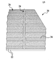
図1を参照すると、例えば非限定的に、エポキシ樹脂マトリックスに保持された強化炭素繊維等の未硬化の複合積層体20は複数層22の繊維強化されたプリプレグ材料を含む。層22の強化繊維は織物又は編物であってよく、多様な繊維配向性のうちのいかなる繊維配向性を有していてもよい。ある場合には、幾つかの層22は樹脂を予め含浸させた単向性繊維を含むことができる。
Referring to FIG. 1, an uncured
積層体20は、例えば非限定的に、積層体20を所望の複合構造体に形作るのに使用される工具(図示せず)の上に形成された積層体26を含むことができる。層22を工具(図示せず)の上に連続的に積み重ねる積層プロセスの間に、バックル又はバックリングとも呼ばれる一又は複数の皺24が層22の幾つか又は全てに形成される可能性がある。ある場合には、皺24は積層体20の層の最上部にのみ存在する可能性がある。
The laminate 20 can include, for example, without limitation, a laminate 26 formed on a tool (not shown) used to form the laminate 20 into a desired composite structure. During the lamination process in which the
皺24は非限定的に、個々の層22が積層される方法の不規則性によって起こる場合があり、又は工具(図示せず)の一部を形成するでこぼこの表面積、角度等に起因する場合がある。どの場合においても、強化繊維を保持するためのマトリックスとして使用される樹脂の粘着性により強化繊維34間の摩擦及び隣接する層22間の摩擦が起こる可能性があり、これにより皺24の伸びが阻止される可能性がある。プリプレグ層22を含む積層体20が図示されているが、開示の方法の実施形態は、後に樹脂が注入され、ここでプリフォームがプリフォーム層の皺を形成しやすくする樹脂バインダを使用する乾燥プリフォームの皺を低減するのにも使用することができることをここで注記すべきである。また、方法の実施形態を複数層の積層体26の皺の低減に関連して示してきたが、この方法はまた、単一層における皺を低減するのにも有利に使用可能であることも注記すべきである。
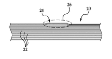
開示の実施形態によれば、皺24の領域の積層体20の表面34に、高周波数、低振幅の振動を加えることによって、皺24を低減することができる、又はある場合には除去することができる。さらに、皺24へ振動エネルギーの印加と同時に圧力を印加することにより、皺24の低減を促進することができる。ある実施形態では、表面34の皺24に係合し圧力を印加する平坦な下面30を有するトランスデューサのヘッド28を用いて、皺24に振動が印加される。
According to the disclosed embodiments, the
トランスデューサのヘッド28は、電力を下面30において増幅されフォーカスされる振動エネルギーに変換する市販の装置を含むことができる。印加される振動の周波数及び振幅は用途、及び、例えば非限定的に、積層体20の厚さ、樹脂マトリックスの種類、強化繊維の直径、トランスデューサのヘッド28のサイズ、及び印加される電力レベルを含む様々な要因によって変化する。600ワットで稼動する1インチのトランスデューサのヘッドを使用したある主用途では、35000Hzの周波数が良い結果をもたらした。他の用途においては、15000〜70000Hzの周波数が良い結果をもたらし得る。好適な振幅の範囲は、トランスデューサのヘッド28の種類及びサイズで変化し得るが、通常は、様々な用途に対して約0.0005〜0.005インチの振幅が好適であり得る。
The
ここで図3を参照すると、ある用途においては、トランスデューサの下面30と積層体20の表面34の間に材料の保護シート36を配置することが有利であり得る。シート36は例えば非限定的に、実質的に平坦な上面37を有するArmalon(登録商標)等のテフロン(登録商標)コーティングされたグラスファイバーファブリックを含むことができる。シート36は、トランスデューサのヘッド28の移動面30との係合によって上層22の繊維が変形する又はそうでなければ乱されることを防止する役割を果たし得る。さらに、シート36はトランスデューサのヘッド28によって印加した圧力を積層体20の表面34により良く分配する機能を持つことができ、その一方で平坦な上面37は皺24と、表面34よりも摩擦が少ないトランスデューサの下面30の間の界面となる。最後に、保護シート36により、トランスデューサのヘッド28が積層体20の表面34に直接係合したときに起こりがちなトランスデューサの下面30の樹脂の蓄積も除去される。
Referring now to FIG. 3, in certain applications it may be advantageous to place a
トランスデューサのヘッド28は、皺24の上を、例えば皺24の方向又は配向に沿って、あるいは前述の配向に対して横方向等、様々ないかなる方向にも動かすことができる。図4は開示の実施形態にしたがって部分的に処理された皺24を示す図である。図4に示すように、皺24のある区域38は、上述した方法を用いて振動エネルギーと圧力を同時に印加することによって実質的に低減、及び実質的に除去されている。
The
図5は積層体20、シート36、及びトランスデューサのヘッド28の積み重ねられた状態を示す図である。シート36は、この場合には皺24が形成される、番号45で指定される3つの上層を含む皺24の領域の上に置かれる。トランスデューサのヘッド28によって、振動エネルギーが印加されるのと同時に、皺24に矢印40の方向に下向きの圧力が加えられる。積層体の層22に引き起こされた高速振動運動は未硬化樹脂の静止摩擦に打ち勝ち、通常束になった繊維が互いに通り過ぎて皺の高さを低減することが可能になる。振動運動はまた、樹脂の粘度を一時的に低減するのに十分な量の摩擦熱も発生させることができ、これによりさらに皺の伸びが促進される。
FIG. 5 is a view showing a stacked state of the laminate 20, the
ある用途では、ヒートガン(図示せず)又は他の好適な熱源を使用してトランスデューサのヘッド28近辺の皺24に追加の熱32を加える、又は積層体20全体を予め加熱することも有利であり得るが、加えた熱が樹脂を硬化させるほど高いものであってはならない。皺24の加熱により、樹脂バインダの粘度を一時的に低下させることができ、これにより強化繊維間の摩擦が低減されて皺24がさらに伸びやすくなる。
In some applications, it may also be advantageous to apply
図6は開示の方法による処理後の図5に示す皺24を示す図である。高周波数、低振幅の振動エネルギーと圧力の同時印加により、強化繊維が互いに滑りあい、皺24が平坦化されることが可能になる。図6では高さが実質的に低減された皺24を示すが、ある用途では皺の基本的な除去が可能である。
FIG. 6 is a diagram showing the
皺が積層体20の同じ通常領域で起こりやすいある高速生産環境では、上述した皺を低減する方法を自動化することが望ましい場合がある。例えば、トランスデューサのヘッド28をコンピュータ(図示せず)又はプログラマブルロジックコントローラ(図示せず)によって制御される多軸ロボット(図示せず)のアーム、又はx、y、zステージ(図示せず)に装着することができる。
In certain high-speed production environments where wrinkles are likely to occur in the same normal region of the laminate 20, it may be desirable to automate the method of reducing wrinkles described above. For example, the
ここで、図1〜6には実施形態を説明しやすくするために単純で直線形の皺24が示されているが、開示の実施形態を使用して、多様な他の形状を有する皺を低減することも可能であることに注目すべきである。例えばわずかな例を挙げると、図7に示すようなおおむね泡の形状の皺24a、図8に示すようなテーパー形状の皺24b、又は図9に示すような交差した皺24cを低減するのにも有用であり得る。
Here, although FIGS. 1-6 show a simple,
上述した皺を低減する方法は、図10のフロー図にさらに示されている。ステップ42で開始し、複数のプリプレグ層22を好適な工具(図示せず)の上に積層する。次にステップ44において積層体に存在する皺を見つけて、そして任意にステップ46において、シート36を積層体の上面の上に配置する。ある用途では、ステップ48に示すように、皺低減プロセスの前(予熱)又は皺低減プロセス中のいずれかにおいて、皺24に熱を任意に加えることができる。ステップ50においては、トランスデューサのヘッド28をシート36と圧接させて、シート36を介して積層体に圧力を印加する。ステップ52では、高周波、低振幅信号をトランスデューサのヘッド28に送って、ヘッドを振動させる。通常、この振動は積層体24の表面34に対して実質的に垂直(すなわち、上下振動)となるが、振動は横方向又は振動性要素を有していてよい。
The method for reducing wrinkles described above is further illustrated in the flow diagram of FIG. Beginning at
ステップ54に示すように、圧力と振動エネルギーを皺24に加え続けながら、トランスデューサのヘッド28を皺24全体において移動させる。上述した皺低減処理に続いて、皺24をステップ56で点検することができ、必要に応じてステップ58に示すように皺を再処理することができる。皺24が実質的に低減又は除去されたら、ステップ60においてトランスデューサのヘッド28と保護シート36を取り外すことができ、続いてステップ62に示すように、通常の方法で積層体を成形し硬化させる。
As shown in
本発明の実施形態は、様々な可能性のある用途、特に例えば航空宇宙、海洋、及び自動車用途を含む運送業において使用することができる。したがって、ここで図11及び12を参照すると、本発明の実施形態は図11に示すような航空機の製造及び就航方法64及び図12に示すような航空機66において使用可能である。試作段階においては、例示の方法64は航空機66の仕様及び設計68と、材料調達70を含むことができる。製造段階においては、航空機66の部品及びサブアセンブリの製造72と、システム統合74がおこなわれる。そのあとに、航空機66は、認可及び納品76を経て就航78される。顧客によって就航されている間、航空機66には所定の整備及び保守80(変更、再構成、改装等も含むことができる)が予定される。
Embodiments of the present invention can be used in a variety of potential applications, particularly in the transportation industry including aerospace, marine, and automotive applications. Thus, referring now to FIGS. 11 and 12, embodiments of the present invention may be used in aircraft manufacturing and
本方法64の各プロセスは、システムインテグレータ、第三者、及び/又はオペレータ(例えば顧客等)によって行う又は実施することができる。この説明のために、システムインテグレータは限定しないが、任意の数の航空機メーカー、及び主要システムの下請け業者を含むことができ;第三者は限定しないが、任意の数の供給メーカー、下請け業者、及びサプライヤを含むことができ;オペレータは、航空会社、リース会社、軍部、サービス組織等であってよい。
Each process of the
図12に示すように、例示の方法64で製造された航空機66は、複数のシステム84と内装86を有する機体82を備えることができる。高レベルシステム84の例は、一又は複数の推進システム88、電気システム90、油圧システム92、及び環境システム94が挙げられる。任意の数の他のシステムを含むことができる。航空宇宙での実施例を示したが、本発明の原理は例えば海洋及び自動車産業等の他の産業分野に応用することが可能である。
As shown in FIG. 12, an
本明細書に具現化されたシステム及び方法は、製造及び就航方法64の任意の一又は複数の段階において採用することができる。例えば、製造プロセス88に対応する部品又はサブアセンブリは、航空機66が就航している間に製造される部品又はサブアセンブリと同じ方法で加工又は製造することができる。また、一又は複数の装置の実施形態、方法の実施形態、又はこれらの組み合わせを、例えば、航空機66を実質的に組立てしやすくする、又は航空機66にかかる費用を削減することによって、製造段階72及び74において用いることが可能である。同様に、一又は複数の装置の実施形態、方法の実施形態、またはこれらの組み合わせを、航空機66が就航している間に、例えば限定しないが、整備及び保守80に用いることができる。
The systems and methods embodied herein may be employed at any one or more stages of the manufacturing and
本発明の実施形態を特定の実例となる実施形態に関連させて説明してきたが、当然ながら特定の実施形態は説明のためであり、限定するものではなく、当業者が他の変形例を発想することが可能である。 While embodiments of the present invention have been described with reference to specific illustrative embodiments, it should be understood that the specific embodiments are illustrative and not limiting, and that other variations will occur to those skilled in the art. Is possible.
Claims (6)
トランスデューサのヘッド(28)を層と接触させて皺に圧力を加えることと、
トランスデューサのヘッド(28)を励起して、15000〜70000Hzの周波数と0.0005インチ(0.00127cm)〜0.005インチ(0.0127cm)の振幅で振動させることによって皺に振動を与えること
を含み、層中に引き起こされた振動運動は未硬化樹脂の静止摩擦に打ち勝ち、繊維が互いに通り過ぎて皺の高さを低減し、振動運動は樹脂の粘度を一時的に低減するのに十分な量の摩擦熱を発生させることができ、これによりさらに皺の伸びが促進される、方法。 A method for reducing wrinkles (24) of a carbon fiber reinforced prepreg resin layer (26) for an aircraft, after laminating the layer (26), and before molding and curing the laminate:
Applying pressure to the heel by bringing the head (28) of the transducer into contact with the layer;
Exciting the head (28) of the transducer to vibrate the heel by vibrating at a frequency of 15000-70000 Hz and an amplitude of 0.0005 inch (0.00127 cm) to 0.005 inch (0.0127 cm). seen including, oscillatory motion caused in the layer overcomes the static friction of the uncured resin, the fibers past one another to reduce the height of the wrinkles, oscillatory motion sufficient to temporarily reduce the viscosity of the resin A method wherein an amount of frictional heat can be generated, which further promotes the elongation of wrinkles .
皺の上でトランスデューサのヘッドを動かす
ことを含む、請求項1に記載の方法。 Giving vibration to the heel:
The method of claim 1, comprising moving a transducer head over the heel.
をさらに含む、請求項1に記載の方法。 The method of claim 1, further comprising applying pressure to the heel using the transducer head while the transducer head is moving over the heel.
をさらに含む、請求項1に記載の方法。 The method of claim 1, further comprising protecting the layer by placing a protective sheet between the transducer head and the heel.
をさらに含む、請求項1に記載の方法。 The method of claim 1, further comprising heating the layer in the heel region.
Applications Claiming Priority (3)
| Application Number | Priority Date | Filing Date | Title |
|---|---|---|---|
| US12/242,536 | 2008-09-30 | ||
| US12/242,536 US9150700B2 (en) | 2008-09-30 | 2008-09-30 | Wrinkle reduction in uncured composite laminates |
| PCT/US2009/058688 WO2010039665A1 (en) | 2008-09-30 | 2009-09-29 | Wrinkle reduction in uncured composite laminates |
Publications (3)
| Publication Number | Publication Date |
|---|---|
| JP2012504183A JP2012504183A (en) | 2012-02-16 |
| JP2012504183A5 JP2012504183A5 (en) | 2012-11-15 |
| JP5841842B2 true JP5841842B2 (en) | 2016-01-13 |
Family
ID=41395898
Family Applications (1)
| Application Number | Title | Priority Date | Filing Date |
|---|---|---|---|
| JP2011529339A Active JP5841842B2 (en) | 2008-09-30 | 2009-09-29 | Reduction of wrinkles in uncured composite laminates |
Country Status (8)
| Country | Link |
|---|---|
| US (1) | US9150700B2 (en) |
| EP (2) | EP2581402B1 (en) |
| JP (1) | JP5841842B2 (en) |
| CN (1) | CN102164994B (en) |
| CA (1) | CA2731893C (en) |
| ES (2) | ES2530501T3 (en) |
| PT (1) | PT2581402E (en) |
| WO (1) | WO2010039665A1 (en) |
Families Citing this family (14)
| Publication number | Priority date | Publication date | Assignee | Title |
|---|---|---|---|---|
| US9586699B1 (en) | 1999-08-16 | 2017-03-07 | Smart Drilling And Completion, Inc. | Methods and apparatus for monitoring and fixing holes in composite aircraft |
| US9625361B1 (en) | 2001-08-19 | 2017-04-18 | Smart Drilling And Completion, Inc. | Methods and apparatus to prevent failures of fiber-reinforced composite materials under compressive stresses caused by fluids and gases invading microfractures in the materials |
| US9150700B2 (en) | 2008-09-30 | 2015-10-06 | The Boeing Company | Wrinkle reduction in uncured composite laminates |
| FR2949208B1 (en) * | 2009-08-18 | 2014-02-21 | Eads Europ Aeronautic Defence | METHOD FOR MANUFACTURING COMPOSITE PARTS FOR REPAIRING SAID PARTS |
| US8795567B2 (en) | 2010-09-23 | 2014-08-05 | The Boeing Company | Method for fabricating highly contoured composite stiffeners with reduced wrinkling |
| US20120139165A1 (en) * | 2011-09-15 | 2012-06-07 | Uli Ramm | Method and system for producing a wind turbine rotor blade |
| EP2802446B1 (en) | 2012-01-13 | 2020-11-18 | Magna International Inc. | Method and system for fabricating a composite article |
| US8826957B2 (en) | 2012-08-31 | 2014-09-09 | General Electric Company | Methods and systems for automated ply layup for composites |
| EP2873517B1 (en) * | 2013-11-14 | 2019-04-24 | Airbus Defence and Space GmbH | Stabilising device, stabilising process and method for producing fibre compound components |
| CN110461918B (en) * | 2017-03-31 | 2022-06-28 | 三菱化学株式会社 | Prepreg and method for producing same, cell layer with skin material, fiber-reinforced composite material molded article, and method for producing same |
| US10703055B2 (en) * | 2017-07-14 | 2020-07-07 | The Boeing Company | Clamping system for holding a composite charge during forming over a forming mandrel |
| CN108839359B (en) * | 2018-06-20 | 2020-12-22 | 中南大学 | Composite material member curing process and composite material part |
| US11597057B2 (en) | 2019-02-01 | 2023-03-07 | Trelleborg Sealing Solutions Germany Gmbh | Impact forming of thermoplastic composites |
| CN113059825B (en) * | 2021-04-01 | 2022-03-29 | 南京航空航天大学 | Method for asynchronously compacting composite material component |
Family Cites Families (12)
| Publication number | Priority date | Publication date | Assignee | Title |
|---|---|---|---|---|
| US6432236B1 (en) * | 1991-03-01 | 2002-08-13 | Foster-Miller, Inc. | Ultrasonic method of fabricating a thermosetting matrix fiber-reinforced composite structure and the product thereof |
| US6511563B2 (en) * | 1991-03-01 | 2003-01-28 | Foster-Miller, Inc. | Device for ultrasonically consolidating fiber reinforced composite structures |
| US5418035A (en) * | 1991-09-12 | 1995-05-23 | Honda Giken Kogyo Kabushiki Kaisha | Thermoplastic composite fabrics and formed article produced therefrom |
| US6592799B1 (en) * | 1996-12-09 | 2003-07-15 | The Boeing Company | Vibration assisted processing of viscous thermoplastics |
| US6017484A (en) * | 1997-01-21 | 2000-01-25 | Harold P. Hale | Method for manufacture of minimum porosity, wrinkle free composite parts |
| JP2002047809A (en) * | 2000-08-04 | 2002-02-15 | Richter Corporation:Kk | Composite material, and manufacturing method and construction thereof |
| JP4372384B2 (en) * | 2002-01-29 | 2009-11-25 | 東レ株式会社 | Preform manufacturing method |
| JP4170781B2 (en) * | 2003-01-17 | 2008-10-22 | 松下電器産業株式会社 | Substrate manufacturing method |
| JP2004330474A (en) * | 2003-05-01 | 2004-11-25 | Kawasaki Heavy Ind Ltd | Method for manufacturing composite material product |
| JP2008208244A (en) * | 2007-02-27 | 2008-09-11 | Asahi Kasei Electronics Co Ltd | Prepreg manufacturing apparatus and manufacturing method |
| US8152948B2 (en) | 2008-01-09 | 2012-04-10 | The Boeing Company | Contoured composite parts |
| US9150700B2 (en) | 2008-09-30 | 2015-10-06 | The Boeing Company | Wrinkle reduction in uncured composite laminates |
-
2008
- 2008-09-30 US US12/242,536 patent/US9150700B2/en active Active
-
2009
- 2009-09-29 ES ES12197711T patent/ES2530501T3/en active Active
- 2009-09-29 JP JP2011529339A patent/JP5841842B2/en active Active
- 2009-09-29 CN CN2009801379050A patent/CN102164994B/en active Active
- 2009-09-29 ES ES09793092T patent/ES2401413T3/en active Active
- 2009-09-29 EP EP20120197711 patent/EP2581402B1/en active Active
- 2009-09-29 WO PCT/US2009/058688 patent/WO2010039665A1/en active Application Filing
- 2009-09-29 PT PT121977110T patent/PT2581402E/en unknown
- 2009-09-29 CA CA 2731893 patent/CA2731893C/en active Active
- 2009-09-29 EP EP20090793092 patent/EP2331612B1/en active Active
Also Published As
| Publication number | Publication date |
|---|---|
| CA2731893A1 (en) | 2010-04-08 |
| PT2581402E (en) | 2015-01-14 |
| CN102164994B (en) | 2013-11-20 |
| JP2012504183A (en) | 2012-02-16 |
| US20100078845A1 (en) | 2010-04-01 |
| US9150700B2 (en) | 2015-10-06 |
| EP2581402B1 (en) | 2014-11-12 |
| CA2731893C (en) | 2014-11-18 |
| EP2331612A1 (en) | 2011-06-15 |
| ES2401413T3 (en) | 2013-04-19 |
| ES2530501T3 (en) | 2015-03-03 |
| EP2581402A1 (en) | 2013-04-17 |
| EP2331612B1 (en) | 2012-12-19 |
| CN102164994A (en) | 2011-08-24 |
| WO2010039665A1 (en) | 2010-04-08 |
Similar Documents
| Publication | Publication Date | Title |
|---|---|---|
| JP5841842B2 (en) | Reduction of wrinkles in uncured composite laminates | |
| US9517594B2 (en) | Composite structure having a stabilizing element | |
| US8123996B2 (en) | Wrinkle control for composite tubes | |
| JP6630480B2 (en) | Production of composite laminates using temporarily sewn preforms | |
| JP6289503B2 (en) | Fabrication of thermoplastic reinforced composite parts | |
| JP6902875B2 (en) | Dynamic molding tool for composite parts | |
| JP6670357B2 (en) | Composite structure and method | |
| KR102528831B1 (en) | High rate production fiber placement system and method | |
| JP7066430B2 (en) | Integrated composite structure manufacturing system | |
| US9427899B2 (en) | Device for compressing a composite radius | |
| US11904560B2 (en) | Vacuum bag-less composite repair systems and methods | |
| US20090218713A1 (en) | Vacuum heat-set of net shape latex vacuum bags | |
| KR20150110308A (en) | Placement of prepreg tows in high angle transition regions | |
| JP2019051702A (en) | Reinforcement panel | |
| JP7253341B2 (en) | Induction Heat Forming and Induction Heat Curing of Thermosetting Composite Charge Materials | |
| JP6530883B2 (en) | Method and apparatus for reducing gaps in composite resin parts | |
| EP3915750A1 (en) | System and method for curing thermoset composites | |
| JP2003211447A (en) | Method for manufacturing preform | |
| EP3921144A1 (en) | Composite material for lightening various structures |
Legal Events
| Date | Code | Title | Description |
|---|---|---|---|
| A521 | Request for written amendment filed |
Free format text: JAPANESE INTERMEDIATE CODE: A523 Effective date: 20120925 |
|
| A621 | Written request for application examination |
Free format text: JAPANESE INTERMEDIATE CODE: A621 Effective date: 20120925 |
|
| A977 | Report on retrieval |
Free format text: JAPANESE INTERMEDIATE CODE: A971007 Effective date: 20140227 |
|
| A131 | Notification of reasons for refusal |
Free format text: JAPANESE INTERMEDIATE CODE: A131 Effective date: 20140318 |
|
| A601 | Written request for extension of time |
Free format text: JAPANESE INTERMEDIATE CODE: A601 Effective date: 20140617 |
|
| A602 | Written permission of extension of time |
Free format text: JAPANESE INTERMEDIATE CODE: A602 Effective date: 20140624 |
|
| A521 | Request for written amendment filed |
Free format text: JAPANESE INTERMEDIATE CODE: A523 Effective date: 20140717 |
|
| A131 | Notification of reasons for refusal |
Free format text: JAPANESE INTERMEDIATE CODE: A131 Effective date: 20150113 |
|
| A601 | Written request for extension of time |
Free format text: JAPANESE INTERMEDIATE CODE: A601 Effective date: 20150413 |
|
| A601 | Written request for extension of time |
Free format text: JAPANESE INTERMEDIATE CODE: A601 Effective date: 20150513 |
|
| A521 | Request for written amendment filed |
Free format text: JAPANESE INTERMEDIATE CODE: A523 Effective date: 20150519 |
|
| TRDD | Decision of grant or rejection written | ||
| A01 | Written decision to grant a patent or to grant a registration (utility model) |
Free format text: JAPANESE INTERMEDIATE CODE: A01 Effective date: 20151020 |
|
| A61 | First payment of annual fees (during grant procedure) |
Free format text: JAPANESE INTERMEDIATE CODE: A61 Effective date: 20151116 |
|
| R150 | Certificate of patent or registration of utility model |
Ref document number: 5841842 Country of ref document: JP Free format text: JAPANESE INTERMEDIATE CODE: R150 |
|
| R250 | Receipt of annual fees |
Free format text: JAPANESE INTERMEDIATE CODE: R250 |
|
| R250 | Receipt of annual fees |
Free format text: JAPANESE INTERMEDIATE CODE: R250 |
|
| R250 | Receipt of annual fees |
Free format text: JAPANESE INTERMEDIATE CODE: R250 |
|
| R250 | Receipt of annual fees |
Free format text: JAPANESE INTERMEDIATE CODE: R250 |
|
| R250 | Receipt of annual fees |
Free format text: JAPANESE INTERMEDIATE CODE: R250 |
|
| R250 | Receipt of annual fees |
Free format text: JAPANESE INTERMEDIATE CODE: R250 |