JP5837348B2 - Motion guide device, drive device - Google Patents
Motion guide device, drive device Download PDFInfo
- Publication number
- JP5837348B2 JP5837348B2 JP2011153097A JP2011153097A JP5837348B2 JP 5837348 B2 JP5837348 B2 JP 5837348B2 JP 2011153097 A JP2011153097 A JP 2011153097A JP 2011153097 A JP2011153097 A JP 2011153097A JP 5837348 B2 JP5837348 B2 JP 5837348B2
- Authority
- JP
- Japan
- Prior art keywords
- rolling element
- rolling
- element rolling
- lid
- loaded
- Prior art date
- Legal status (The legal status is an assumption and is not a legal conclusion. Google has not performed a legal analysis and makes no representation as to the accuracy of the status listed.)
- Active
Links
Images


Landscapes
- Bearings For Parts Moving Linearly (AREA)
- Transmission Devices (AREA)
Description
本発明は、運動案内装置及び駆動装置に係り、特に、シール部材やパッキン部材を備える運動案内装置及び駆動装置に関するものである。 The present invention relates to a motion guide device and a drive device, and more particularly to a motion guide device and a drive device including a seal member and a packing member.
従来から、リニアガイド等といった運動案内装置や、ボールねじ等といった駆動装置が知られている。これらのうち、運動案内装置は、長手方向に転動体転走面を有する軌道部材と、前記転動体転走面に対向する負荷転動体転走面と、当該負荷転動体転走面と平行な無負荷転動体転走路とを有する移動部材と、前記転動体転走面と前記負荷転動体転走面とで構成される負荷転動体転走路に転動自在に配設される複数の転動体と、を備えることにより、軌道部材に対する移動部材の相対的な直線運動が自在とされた装置である。また、駆動装置は、長手方向に螺旋状をした転動体転走面を有する軸部材と、前記転動体転走面に対向する螺旋状をした負荷転動体転走面と、前記軸部材と平行な無負荷転動体転走路を有する可動部材と、前記転動体転走面と前記負荷転動体転走面とで構成される負荷転動体転走路に転動自在に配設される複数の転動体と、を備えることにより、軸部材に対する可動部材の相対的な回転運動が自在とされた装置である。 Conventionally, a motion guide device such as a linear guide and a drive device such as a ball screw are known. Among these, the motion guide device includes a raceway member having a rolling element rolling surface in the longitudinal direction, a loaded rolling element rolling surface facing the rolling element rolling surface, and a parallel to the loaded rolling element rolling surface. A plurality of rolling elements arranged in a freely rolling manner on a loaded rolling element rolling path comprising a moving member having an unloaded rolling element rolling path, and the rolling element rolling surface and the loaded rolling element rolling surface. And the linear movement of the moving member relative to the track member is made freely. Further, the driving device includes a shaft member having a rolling element rolling surface spiraled in the longitudinal direction, a spiral loaded rolling element rolling surface facing the rolling element rolling surface, and a parallel to the shaft member. A plurality of rolling elements that are freely rollable on a loaded rolling element rolling path comprising a movable member having an unloaded rolling element rolling path, and the rolling element rolling surface and the loaded rolling element rolling surface The apparatus can freely rotate the movable member relative to the shaft member.
この種の装置では、軌道部材と移動部材、あるいは軸部材と可動部材との間に配設される複数の転動体が繰り返し転がり運動を行うことになるので、これら装置の構成部材には繰り返し接触応力が加わることとなっている。そのため、この種の装置を構成する部材には、疲労寿命や耐摩耗性に優れた金属材料や樹脂材料等が採用されている。また、この種の装置は、精度の高い案内運動や駆動動作が求められ、さらに、あらゆる環境下で安定して使用できることが求められるため、例えば、軌道部材と移動部材、あるいは軸部材と可動部材との間にシール部材を設置することで防塵性を高めたり、あるいは構成部品の間に存在する隙間を塞ぐパッキン部材を設置することで構成部品間の密閉性を高めたりすることが行われていた。 In this type of device, a plurality of rolling elements arranged between the track member and the moving member, or between the shaft member and the movable member perform repeated rolling motion, so that the constituent members of these devices are repeatedly contacted. Stress is to be applied. Therefore, a metal material, a resin material, etc. excellent in fatigue life and wear resistance are adopted as members constituting this type of apparatus. In addition, since this type of device is required to have a highly accurate guide motion and drive operation, and further to be able to be used stably in any environment, for example, a track member and a moving member, or a shaft member and a movable member. It is done to improve the dust resistance by installing a seal member between the two, or to improve the sealing performance between the component parts by installing a packing member that closes the gap between the component parts It was.
なお、上述したシール部材やパッキン部材を備える駆動装置を開示する先行技術文献として、例えば下記特許文献1が存在している。 As a prior art document disclosing a driving device including the above-described seal member and packing member, for example, there is Patent Document 1 below.
ところで、上述したシール部材やパッキン部材は、例えばリニアガイドに用いられる場合には移動ブロックの構成部品であるエンドプレートに取り付けられているが、これら従来のシール部材やパッキン部材は、エンドプレートとは別部材として製造され、組み立てられるものであった。そこで、エンドプレートとシール部材やパッキン部材を一体化して製造できれば、部品点数の削減や製造工程の減少につながるので、製造コストを削減できるというメリットを得られることとなる。 By the way, the seal member and packing member described above are attached to an end plate which is a component part of a moving block when used in, for example, a linear guide. However, these conventional seal members and packing members are different from end plates. It was manufactured and assembled as a separate member. Therefore, if the end plate, the seal member, and the packing member can be manufactured in an integrated manner, the number of components and the manufacturing process can be reduced, so that the merit that the manufacturing cost can be reduced can be obtained.
しかしながら、エンドプレートとシール部材やパッキン部材を一体化して製造するには、製造技術上の制約を考慮した部材形状を採用しなければならず、また、金型を用いて樹脂材料を成形するに際しては、樹脂材料の冷却時の収縮率や金型内での油流れ等を考慮して、適切な製品形状を設計しなければならない。すでに、本出願人は、エンドプレート等の部品とシール部材やパッキン部材とを2色成形技術を用いて一体化して製造し、一部品として提供することを提案していたが、さらに本発明者らは、2色成形技術を用いて一体成形されたエンドプレートとシール部材及びパッキン部材を量産化するにあたり、鋭意努力の結果、製造が容易であり、品質不良が少なく、製造コストを軽減することのできる製品形状を実現するに至った。 However, in order to manufacture the end plate and the seal member or packing member in an integrated manner, it is necessary to adopt a member shape that takes into account restrictions in manufacturing technology, and when molding a resin material using a mold. Therefore, it is necessary to design an appropriate product shape in consideration of the shrinkage rate when the resin material is cooled and the oil flow in the mold. The present applicant has already proposed that a component such as an end plate and a seal member or a packing member are integrally manufactured using a two-color molding technique and provided as a single component. And others, as a result of diligent efforts to mass-produce the end plate, seal member, and packing member that are integrally molded using the two-color molding technology, the manufacturing should be easy, quality defects should be reduced, and manufacturing costs should be reduced. To achieve a product shape that can be used.
すなわち、本発明は、2色成形技術によってエンドプレート等の部品とシール部材やパッキン部材とを一体化された部品として量産化するに当たり、製造が容易であり、品質不良が少なく、製造コストを軽減することのできる形状を有した製品の提供を目的として成されたものである。 That is, the present invention is easy to manufacture, reduces quality defects, and reduces manufacturing costs when mass-producing parts such as end plates and seal members and packing members as an integrated part by two-color molding technology. It was made for the purpose of providing a product having a shape that can be used.
上述した目的を達成するために、本発明に係る運動案内装置は、長手方向に転動体転走面を有する軌道部材と、前記転動体転走面に対向する負荷転動体転走面と、当該負荷転動体転走面と平行な無負荷転動体転走路とを有する移動部材と、前記転動体転走面と前記負荷転動体転走面とで構成される負荷転動体転走路に転動自在に配設される複数の転動体と、を備える運動案内装置であって、前記移動部材の端部には、前記負荷転動体転走路と前記無負荷転動体転走路とをつなぐ方向転換路を有する蓋部が設置されており、前記蓋部は、蓋本体部と、前記軌道部材に対して隙間なく摺接するように設置されるシール部材と、前記移動部材における前記蓋部の設置面を塞ぐパッキン部材と、を備えるとともに、前記蓋本体部、前記シール部材、及び前記パッキン部材は、2色成形により成形されており、さらに、前記シール部材と不連続に形成される前記パッキン部材を少なくとも1つ備え、前記蓋本体部には、複数の貫通孔が形成され、前記シール部材及び前記パッキン部材の少なくとも一方は、前記複数の貫通孔を導通する柱状形状を有して構成されており、さらに、前記柱状形状は、長手方向における一部の箇所で幅方向の径寸法が異なるように形成されることで、抜け止め形状を有して形成されていることを特徴とするものである。また、本発明に係る運動案内装置は、長手方向に転動体転走面を有する軌道部材と、前記転動体転走面に対向する負荷転動体転走面と、当該負荷転動体転走面と平行な無負荷転動体転走路とを有する移動部材と、前記転動体転走面と前記負荷転動体転走面とで構成される負荷転動体転走路に転動自在に配設される複数の転動体と、を備える運動案内装置であって、前記移動部材の端部には、前記負荷転動体転走路と前記無負荷転動体転走路とをつなぐ方向転換路を有する蓋部が設置されており、前記蓋部は、蓋本体部と、前記軌道部材に対して隙間なく摺接するように設置されるシール部材と、前記移動部材における前記蓋部の設置面を塞ぐパッキン部材と、を備えるとともに、前記蓋本体部、前記シール部材、及び前記パッキン部材は、2色成形により成形されており、さらに、前記シール部材と不連続に形成される前記パッキン部材を少なくとも1つ備え、前記蓋本体部には、複数の係止穴が形成されており、前記シール部材及び前記パッキン部材の少なくとも一方は、前記複数の係止穴に嵌り込む係止部材を有して形成されていることを特徴とするものである。 In order to achieve the above-described object, a motion guide device according to the present invention includes a raceway member having a rolling element rolling surface in a longitudinal direction, a loaded rolling element rolling surface facing the rolling element rolling surface, Rollable to a loaded rolling element rolling path comprising a moving member having an unloaded rolling element rolling path parallel to the loaded rolling element rolling surface, and the rolling element rolling surface and the loaded rolling element rolling surface. A plurality of rolling elements disposed on the movement member, and a direction change path connecting the loaded rolling element rolling path and the unloaded rolling element rolling path is provided at an end of the moving member. The lid portion has a lid portion, and the lid portion closes a lid main body portion, a seal member that is slidably contacted with the raceway member, and an installation surface of the lid portion in the moving member. A packing member, and the lid main body portion, the seal member, and The packing member is molded by two-color molding, further, the seal member and discontinuously formed with at least one of said packing member, the lid body portion, a plurality of through holes are formed, At least one of the seal member and the packing member is configured to have a columnar shape that conducts the plurality of through holes, and the columnar shape has a diameter in the width direction at a part of the longitudinal direction. by dimensions are formed differently and is characterized that you have been formed with a retaining shape. The motion guide device according to the present invention includes a raceway member having a rolling element rolling surface in a longitudinal direction, a loaded rolling element rolling surface facing the rolling element rolling surface, and the loaded rolling element rolling surface. A plurality of movable members arranged on a rolling member rolling path including a moving member having a parallel unloaded rolling member rolling path, and the rolling element rolling surface and the loaded rolling member rolling surface. A rolling guide, and a lid having a direction change path connecting the loaded rolling element rolling path and the unloaded rolling element rolling path is installed at an end of the moving member. The lid portion includes a lid body portion, a seal member installed so as to be in sliding contact with the track member without a gap, and a packing member that closes an installation surface of the lid portion in the moving member. , The lid main body, the seal member, and the packing member are 2 The sealing member is formed by molding, further includes at least one packing member formed discontinuously with the sealing member, and a plurality of locking holes are formed in the lid main body portion, and the sealing member and At least one of the packing members has a locking member that fits into the plurality of locking holes.
また、本発明に係る駆動装置は、長手方向に螺旋状をした転動体転走面を有する軸部材と、前記転動体転走面に対向する螺旋状をした負荷転動体転走面と、前記軸部材と平行な無負荷転動体転走路を有する可動部材と、前記転動体転走面と前記負荷転動体転走面とで構成される負荷転動体転走路に転動自在に配設される複数の転動体と、を備える駆動装置であって、前記可動部材には、負荷転動体転走路と無負荷転動体転走路とをつなぐ循環部が蓋部に設置されており、前記蓋部は、蓋本体部と、前記軸部材に対して隙間なく摺接するように設置されるシール部材と、前記可動部材における前記蓋部の設置面を塞ぐパッキン部材と、を備えるとともに、前記蓋本体部、前記シール部材、及び前記パッキン部材は、2色成形により成形されており、さらに、前記シール部材と不連続に形成される前記パッキン部材を少なくとも1つ備え、前記蓋本体部には、複数の貫通孔が形成され、前記シール部材及び前記パッキン部材の少なくとも一方は、前記複数の貫通孔を導通する柱状形状を有して構成されており、さらに、前記柱状形状は、長手方向における一部の箇所で幅方向の径寸法が異なるように形成されることで、抜け止め形状を有して形成されていることを特徴とするものである。さらに、本発明に係る駆動装置は、長手方向に螺旋状をした転動体転走面を有する軸部材と、前記転動体転走面に対向する螺旋状をした負荷転動体転走面と、前記軸部材と平行な無負荷転動体転走路を有する可動部材と、前記転動体転走面と前記負荷転動体転走面とで構成される負荷転動体転走路に転動自在に配設される複数の転動体と、を備える駆動装置であって、前記可動部材には、負荷転動体転走路と無負荷転動体転走路とをつなぐ循環部が蓋部に設置されており、前記蓋部は、蓋本体部と、前記軸部材に対して隙間なく摺接するように設置されるシール部材と、前記可動部材における前記蓋部の設置面を塞ぐパッキン部材と、を備えるとともに、前記蓋本体部、前記シール部材、及び前記パッキン部材は、2色成形により成形されており、さらに、前記シール部材と不連続に形成される前記パッキン部材を少なくとも1つ備え、前記蓋本体部には、複数の係止穴が形成されており、前記シール部材及び前記パッキン部材の少なくとも一方は、前記複数の係止穴に嵌り込む係止部材を有して形成されていることを特徴とするものである。 The drive device according to the present invention includes a shaft member having a rolling element rolling surface spiraled in a longitudinal direction, a loaded rolling element rolling surface having a spiral shape facing the rolling element rolling surface, A movable member having a no-load rolling element rolling path parallel to the shaft member, and a load rolling element rolling path composed of the rolling element rolling surface and the loaded rolling element rolling surface is disposed to be freely rollable. A driving device comprising a plurality of rolling elements, wherein the movable member is provided with a circulation part that connects the loaded rolling element rolling path and the unloaded rolling element rolling path in the lid part, and the lid part is A lid main body, a seal member installed so as to be in sliding contact with the shaft member without a gap, and a packing member that closes an installation surface of the lid in the movable member, and the lid main body, The seal member and the packing member are molded by two-color molding. Further, the sealing member and discontinuously formed with at least one of said packing member, the lid body portion, a plurality of through holes are formed, at least one of the sealing member and the packing member, the It is configured to have a columnar shape that conducts through a plurality of through-holes, and the columnar shape is formed so that the diameter in the width direction is different at some locations in the longitudinal direction, thereby preventing the columnar shape. those characterized that you have been formed with a shape. Furthermore, the drive device according to the present invention includes a shaft member having a rolling element rolling surface spiraled in the longitudinal direction, a spiral loaded rolling element rolling surface facing the rolling element rolling surface, A movable member having a no-load rolling element rolling path parallel to the shaft member, and a load rolling element rolling path composed of the rolling element rolling surface and the loaded rolling element rolling surface is disposed to be freely rollable. A driving device comprising a plurality of rolling elements, wherein the movable member is provided with a circulation part that connects the loaded rolling element rolling path and the unloaded rolling element rolling path in the lid part, and the lid part is A lid main body, a seal member installed so as to be in sliding contact with the shaft member without a gap, and a packing member that closes an installation surface of the lid in the movable member, and the lid main body, The seal member and the packing member are molded by two-color molding. In addition, at least one packing member formed discontinuously with the seal member is provided, and a plurality of locking holes are formed in the lid main body, and at least the seal member and the packing member One is characterized by having a locking member that fits into the plurality of locking holes.
本発明によれば、2色成形技術によってエンドプレート等の部品とシール部材やパッキン部材とを一体化された部品として量産化するに際して、製造が容易であり、品質不良が少なく、製造コストを軽減することのできる形状を有する製品を提供することができる。 According to the present invention, when mass-producing a component such as an end plate and a sealing member or packing member as an integrated component by two-color molding technology, manufacturing is easy, quality defects are reduced, and manufacturing cost is reduced. A product having a shape that can be provided can be provided.
以下、本発明を実施するための好適な実施形態について、図面を用いて説明する。なお、以下の実施形態は、各請求項に係る発明を限定するものではなく、また、実施形態の中で説明されている特徴の組み合わせの全てが発明の解決手段に必須であるとは限らない。 DESCRIPTION OF EXEMPLARY EMBODIMENTS Hereinafter, preferred embodiments for carrying out the invention will be described with reference to the drawings. The following embodiments do not limit the invention according to each claim, and all combinations of features described in the embodiments are not necessarily essential to the solution means of the invention. .
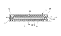
まず、図1及び図2を用いて、本実施形態に係る運動案内装置としてのリニアガイド装置10の全体構成について説明する。ここで、図1は、本実施形態に係るリニアガイド装置の一形態を例示する外観斜視図である。また、図2は、図1で示したリニアガイド装置が備える無限循環路を説明するための断面図である。
First, the overall configuration of a
本実施形態に係る運動案内装置としてのリニアガイド装置10は、軌道部材としての軌道レール11と、軌道レール11に多数の転動体として設置されるボール12…を介してスライド可能に取り付けられた移動部材としての移動ブロック13とを備えている。軌道レール11には、取付手段としてのボルトを軌道レール11の上面から下面に通すことで、軌道レール11をベースに取り付けるためのボルト孔11bが等間隔で形成されており、このボルト孔11bを利用することで、軌道レール11が基準面に固定設置できるようになっている。また、軌道レール11は、その長手方向と直交する断面が概略矩形状に形成された長尺の部材であり、その表面(上面及び両側面)には、ボール12…が転がる際の軌道になる軌道面としての転動体転走面11a…が軌道レール11の全長に亘って形成されている。
A
軌道レール11については、直線的に伸びるように形成されることもあるし、曲線的に伸びるように形成されることもある。また、図1及び図2において例示する転動体転走面11a…の本数は左右で2条ずつ合計4条設けられているが、その条数はリニアガイド装置10の用途等に応じて任意に変更することができる。
The
一方、移動ブロック13には、転動体転走面11a…とそれぞれ対応する位置に軌道面としての負荷転動体転走面13a…が設けられている。軌道レール11の転動体転走面11a…と移動ブロック13の負荷転動体転走面13a…とによって負荷転動体転走路22…が形成され、複数のボール12…が挟まれている。また、移動ブロック13には、各転動体転走面11a…と平行に伸びる4条の無負荷転動体転走路23…がその内部に形成されている。
On the other hand, the moving
さらに、移動ブロックの移動方向の両端部には、一対の蓋部17,17が設置されている。この一対の蓋部17,17には、それぞれに方向転換路25が設けられている。この方向転換路25は、無負荷転動体転走路23…の端と負荷転動体転走路22…の端とを結ぶことができるように構成されている。したがって、1つの負荷転動体転走路22及び無負荷転動体転走路23と、それらを結ぶ一対の方向転換路25,25との組み合わせによって、1つの無限循環路が構成されている(図2参照)。
Furthermore, a pair of
そして、複数のボール12…が、負荷転動体転走路22と無負荷転動体転走路23と一対の方向転換路25,25とから構成される無限循環路に無限循環可能に設置されることにより、移動ブロック13が軌道レール11に対して相対的に往復運動可能となっている。
A plurality of
また、一対の蓋部17,17のそれぞれには、一対の方向転換路25,25の外側において移動ブロック13と軌道レール11との隙間を塞ぐように、シール部材としての一対のエンドシール15,15が設置されている。このエンドシール15は、軌道レール11との接触箇所にリップ部を備えることができ、このリップ部もしくはエンドシール15自体が軌道レール11に対して隙間なく摺接することで、リニアガイド装置10に対して防塵効果を付与することができるようになっている。
In addition, each of the pair of
さらに、移動ブロック13と一対の蓋部17,17との間には、図1及び図2では図示を省略したパッキン部材が挟み込まれている。この不図示のパッキン部材は、移動ブロック13における蓋部17の設置面を塞ぐ機能を発揮しており、移動ブロック13と蓋部17の間に存在する隙間を塞ぐことで、移動ブロック13と蓋部17との密閉性を高める役割を果たしている。
Further, a packing member (not shown in FIGS. 1 and 2) is sandwiched between the moving
以上、本実施形態に係るリニアガイド装置10の全体構成について説明したが、本実施形態において特徴的な構成は、蓋部17に対して一体的に成形されたエンドシール15及びパッキン部材の形状にある。そこで、次に、蓋部17に対して一体的に成形されるエンドシール15及びパッキン部材の形状について、図3〜図8を用いて詳細に説明を行うこととする。
The overall configuration of the
ここで、図3及び図4は、本実施形態に係る蓋部の外観形状を示す外観斜視図であり、図3が反移動ブロック側の面を示しており、図4が移動ブロック側の面を示している。また、図5及び図6は、エンドシール15及びパッキン部材16を蓋部17から取り除いて蓋本体部18のみにした状態の外観斜視図であり、図5が反移動ブロック側の面を示しており、図6が移動ブロック側の面を示している。さらに、図7及び図8は、蓋部17から蓋本体部18を取り除いてエンドシール15及びパッキン部材16のみにした状態の外観斜視図であり、図7が反移動ブロック側から見た状態を示しており、図8が移動ブロック側から見た状態を示している。なお、詳細は後述するが、本実施形態の蓋部17については、蓋本体部18、エンドシール15及びパッキン部材16が2色成形によって一体的に成形されているので、各部材を分割することはできず、常には図3及び図4の状態となっている。すなわち、図5〜図8は、説明の便宜のために描かれた分解図である。
Here, FIG. 3 and FIG. 4 are external perspective views showing the external shape of the lid according to the present embodiment, FIG. 3 shows the surface on the anti-moving block side, and FIG. 4 shows the surface on the moving block side Is shown. 5 and 6 are external perspective views of the state in which the
図3及び図4に示すように、本実施形態の蓋部17は、蓋本体部18と、シール部材としてのエンドシール15と、パッキン部材16とによって構成されており、これら3つの部材は、2色成形によって一体的に成形がなされている。
As shown in FIGS. 3 and 4, the
蓋本体部18は、蓋部17の外郭形状を構成する部材であり、移動ブロック13の両端に取り付けられる部材である。したがって、蓋本体部18には、複数のボルト取付孔18aが形成されており、移動ブロック13への確実な取り付けが可能となっている。また、蓋本体部18には、エンドシール15とパッキン部材16が成形される位置に凹部18bが形成されている。したがって、この凹部18bに対してエンドシール15とパッキン部材16が嵌り込むように成形されることで、蓋本体部18、エンドシール15及びパッキン部材16という3つの部材の安定した一体化が図られている。
The lid
本実施形態のシール部材であるエンドシール15は、軌道レール11に対して隙間なく摺接するように設置される部材である。したがって、軌道レール11に対して移動ブロック13が相対的な直線移動を行う際には、移動ブロック13とともに直線移動するエンドシール15が軌道レール11に常に接触し、軌道レール11と移動ブロック13の間の隙間を塞ぐように構成されている。このエンドシール15が機能することにより、例えば外部からの塵芥等が移動ブロック13内に侵入することを防止している。
The
本実施形態のパッキン部材16は、移動ブロック13に対して蓋部17が取り付けられる際に、移動ブロック13と蓋本体部18との間に挟み込まれる部材である。つまり、パッキン部材16は、移動ブロック13における蓋部17の設置面を塞ぐ部材として機能しており、移動ブロック13と蓋部17との接合箇所の密閉度を高める役割を担っている。特に、移動ブロック13内部には、複数のボール12が無限循環路内で転がり運動を繰り返しており、また、オイルやグリス等の潤滑剤が付与されている。このような移動ブロック内に存在している潤滑剤等が蓋部17との設置面の隙間から漏れださないようにするために、パッキン部材16が機能している。
The packing
以上のように、蓋本体部18、エンドシール15及びパッキン部材16という3つの部材が2色成形によって一体的に成形されて構成される蓋部17であるが、本実施形態に係る蓋部17は、さらなる有意な形態的特徴を有している。
As described above, the
まず、本実施形態に係る蓋部17にあっては、エンドシール15とパッキン部材16の形成される範囲が、最小限の範囲に限定されている。したがって、エンドシール15とパッキン部材16とは、移動ブロック13の移動方向から見たときに、重畳する面積が少なくなるようになっている。その結果、本実施形態の蓋部17では、エンドシール15と不連続に形成されるパッキン部材を少なくとも1つ備える構成となっている(図7及び図8に詳しく描かれている。)。かかる構成は、2色成形時における成形品質の向上を図る観点から採用された構成である。すなわち、本実施形態に係る蓋部17を2色成形する場合には、一次側となる蓋本体部18を成形した後に、二次側となるエンドシール15とパッキン部材16を成形することとなるが、二次側の成形部材の範囲(体積)が大きいと、冷却時のひけ等で歪が生じ易く、金型の成形や成形時の制御が非常に困難となる。そこで、二次側の成形部材の形成範囲(体積)を最小限にとどめることにより、成形時の材料の形状予測が容易となり、好適な金型設計が可能となったのである。また、エンドシール15とパッキン部材16の形成範囲を最小限としたことで、材料コストの削減にもつながり、製造コストの削減効果も得ることができた。
First, in the
また、本実施形態に係る蓋部17にあっては、蓋本体部18とエンドシール15との接続形状にも優位な特徴がある。上述したように、エンドシール15は、移動ブロック13が軌道レール11に対して相対的に直線移動する際に、常に軌道レール11と隙間なく接触して摺動抵抗を受けることになるので、エンドシール15は蓋本体部18に対して確実に一体成形されている必要がある。そこで、本実施形態では、蓋本体部18に対して複数の貫通孔18cを形成しておき、一方で、エンドシール15は、蓋本体部18が有する複数の貫通孔18cを導通する柱状形状15cを有するように成形される。また、複数の貫通孔18cの先端部分は、径寸法が広く形成されているので、その箇所に二次側として成形される柱状形状15cには、先端部分の径寸法が広くなった抜け止め形状15c’が形成されることとなる。このような抜け止め形状15c’を有する柱状形状15cと、このような柱状形状15cが嵌り込む貫通孔18cとの作用によって、蓋本体部18に対するエンドシール15の確実な一体化が実現されることとなる。
Further, the
なお、本実施形態では、エンドシール15に対して抜け止め形状15c’を有する柱状形状15cを形成したが、この柱状形状については、パッキン部材16に対して形成してもよい。
In the present embodiment, the
また、本実施形態で例示した抜け止め形状15c’を有する柱状形状15cは、円柱形状として成形されていたが、本発明の柱状形状及び抜け止め形状の形態については、本実施形態と同様の作用効果を発揮できるものであれば、どの様なものであってもよい。すなわち、本発明の柱状形状は、長手方向における一部の箇所で幅方向の径寸法が異なるように抜け止め形状が形成されていればよく、例えば、径寸法が広くなった抜け止め形状15c’が形成される位置は、柱状形状15cの先端部分以外の位置(例えば、柱状形状15cの中間位置など)であってもよいし、また例えば、柱状形状全体が円錐形状で形成されることで、柱状形状全体として抜け止め形状を形成するものであってもよい。
In addition, the
以上、蓋本体部18とエンドシール15との確実な固定状態を実現するための構成として、複数の貫通孔18cと抜け止め形状15c’を有する柱状形状15cとの組み合わせを説明したが、本実施形態では、蓋本体部18に対するエンドシール15及びパッキン部材16のズレ止めのために、さらなる構成が付加されている。すなわち、蓋本体部18には、上述した複数の貫通孔18cの他に、さらに複数の係止穴18dが形成されており、一方、エンドシール15及びパッキン部材16には、複数の係止穴18dに嵌り込む係止部材15d,16dが形成されている。本実施形態の蓋本体部18に形成された係止穴18dは、蓋本体部18を貫通するように形成してもよいし、貫通せずに、蓋本体部18の表面から部材の途中位置まで形成されていてもよい。このような係止穴18dに対して、エンドシール15が有する円柱状の係止部材15dやパッキン部材16が有する円柱状の係止部材16dが嵌り込むことによって、蓋本体部18に対するエンドシール15及びパッキン部材16の確実なズレ止めが実現されることとなる。
As described above, the combination of the plurality of through
以上の構成により、本実施形態に係るエンドシール15は、抜け止め形状15c’を有する柱状形状15cと係止部材15dという2つの形状の作用によって、蓋本体部18に対する確実な固定状態が維持されることとなる。また、本実施形態に係るパッキン部材16は、係止部材16dの作用によって確実な位置決めとズレ止めが成された上で、移動ブロック13と蓋本体部18とに挟み込まれることになるので、パッキン部材16は常に好適な位置で挟まれることとなり、パッキン部材としての機能を確実に発揮することが可能となる。したがって、製造が容易であり、品質不良が少なく、製造コストを軽減することのできる形状を有する運動案内装置を提供することができる。
With the above configuration, the
なお、本実施形態に係るパッキン部材16には、移動ブロック13との当接面側に凸形状16aが形成されている。この凸形状16aを図9にて詳細に示す。なお、図9において、分図(a)は、パッキン部材16のうち、エンドシール15と不連続に形成されるパッキン部材16の移動ブロック側の面を示しており、分図(b)は、分図(a)中のA−A断面を示している。本実施形態に係る凸形状16aは、パッキン部材16が移動ブロック13に設置される際の蓋部17の密閉性を高めるために機能する形状であり、パッキン部材16が移動ブロック13と蓋部17との間に挟み込まれた際に、凸形状16aが押し潰されることで移動ブロック13と蓋部17との間の隙間が確実に閉塞されることとなる。かかる作用によって、本実施形態に係るパッキン部材16の機能をさらに高める効果が発揮されている。
In the packing
以上、本発明に係る運動案内装置がリニアガイド装置10として構成される場合について、図1〜図9を用いて説明を行った。ただし、本発明は、リニアガイド装置等の運動案内装置だけではなく、ボールねじ装置等の駆動装置に対しても適用可能である。そこで、次に、本発明を適用可能な駆動装置であるボールねじ装置の形態例を、図10を用いて説明する。
The case where the motion guide device according to the present invention is configured as the
図10は、本実施形態に係る駆動装置としてのボールねじ装置の構成を説明するための部分破断斜視図である。本実施形態に係る駆動装置としてのボールねじ装置40は、表面に螺旋状をした転動体転走面42を有する軸部材としてのねじ軸41と、ねじ軸41が有する転動体転走面42と対向する螺旋状の負荷転動体転走面42を有する可動部材としてのナット部材51と、ねじ軸41とナット部材51との間に介装される複数の転動体としてのボール61とを備えている。
FIG. 10 is a partially broken perspective view for explaining the configuration of the ball screw device as the driving device according to the present embodiment. A
ねじ軸41は、軸線方向に延びて形成される部材であり、このねじ軸41に組み付けられたナット部材51が相対的な回転運動をしながらねじ軸41の軸線方向に沿って往復運動できるようになっている。また、ねじ軸41の外表面には螺旋状の転動体転走面42が形成されており、複数のボール61が転動体転走面42内で負荷を受けながら転動自在となっている。
The
ナット部材51は、中央部に配置されたナット本体部53と、このナット本体部53の両端に配置された蓋部としての一対のエンドキャップ54,54とを備えている。ナット本体部53は、軸線方向に貫通するねじ軸貫通孔55を有しており、このねじ軸貫通孔55に上述したねじ軸41が導通可能となっている。ねじ軸貫通孔55の内周面には、ねじ軸41に形成された螺旋状をした転動体転走面42に対向する螺旋状の負荷転動体転走面52が形成されており、これら転動体転走面42と負荷転動体転走面52とによって、負荷転動体転走路56が構成される。
The
また、ナット部材51には、ナット本体部53を貫通する無負荷転動体転走路57と、一対のエンドキャップ54,54のそれぞれに形成された循環部としての方向転換路58が形成されており、この方向転換路58が負荷転動体転走路56と無負荷転動体転走路57の端部をつなぐことにより、負荷転動体転走路56、無負荷転動体転走路57および一対の方向転換路58,58によって形成される無限循環路が構成されている。
Further, the
そして、本実施形態に係るボールねじ装置40では、無限循環路内に複数のボール61が配設されているので、ねじ軸41に対してナット部材51が相対的な回転運動を行うことにより、ねじ軸41に対するナット部材51の相対的な往復運動が可能となっている。
In the
このようなボールねじ装置40において、本実施形態に係る蓋部としてのエンドキャップ54には、軸部材であるねじ軸41に対して隙間なく摺接するように設置されるシール部材54bと、可動部材であるナット部材51との設置面を塞ぐ不図示のパッキン部材とが設置されている。そして、このようなエンドキャップ54に対してシール部材54bとパッキン部材(不図示)とを2色成形により一体成形するとともに、図3〜図9で説明した特徴的な形態を付加することにより、製造が容易であり、品質不良が少なく、製造コストを軽減することのできるボールねじ装置40を提供することが可能となる。
In such a
以上、本発明の好適な実施形態について説明したが、本発明の技術的範囲は上記実施形態に記載の範囲には限定されない。上記実施形態には、多様な変更又は改良を加えることが可能である。 As mentioned above, although preferred embodiment of this invention was described, the technical scope of this invention is not limited to the range as described in the said embodiment. Various modifications or improvements can be added to the embodiment.
例えば、図1〜図8で例示したシール部材はエンドシール15であったが、本発明を適用可能なシール部材はこれに限られず、サイドシールやインナシール、ダブルシール、あるいはスクレーパなどと呼ばれるシール部材全般に対して適用可能である。
For example, the seal member illustrated in FIGS. 1 to 8 is the
また、上述したリニアガイド装置10やボールねじ装置40は、転動体としてボール12,61を用いたものであったが、ローラやコロなどの他の転動体を用いた運動案内装置や駆動装置に対して本発明を適用することも可能である。
Further, the
その様な変更又は改良を加えた形態も本発明の技術的範囲に含まれ得ることが、特許請求の範囲の記載から明らかである。 It is apparent from the description of the scope of claims that embodiments with such changes or improvements can be included in the technical scope of the present invention.
10 リニアガイド装置、11 軌道レール、11a 転動体転走面、11b ボルト孔、12 ボール、13 移動ブロック、13a 負荷転動体転走面、15 エンドシール、15c 柱状形状、15c’ 抜け止め形状、15d 係止部材、16 パッキン部材、16a 凸形状、16d 係止部材、17 蓋部、18 蓋本体部、18a ボルト取付孔、18b 凹部、18c 貫通孔、18d 係止穴、22 負荷転動体転走路、23 無負荷転動体転走路、25 方向転換路、40 ボールねじ装置、41 ねじ軸、51 ナット部材、52 負荷転動体転走面、53 ナット本体部、54 エンドキャップ、54b シール部材、55 ねじ軸貫通孔、56 負荷転動体転走路、57 無負荷転動体転走路、58 方向転換路、61 ボール。
DESCRIPTION OF
Claims (6)
前記転動体転走面に対向する負荷転動体転走面と、当該負荷転動体転走面と平行な無負荷転動体転走路とを有する移動部材と、
前記転動体転走面と前記負荷転動体転走面とで構成される負荷転動体転走路に転動自在に配設される複数の転動体と、
を備える運動案内装置であって、
前記移動部材の端部には、前記負荷転動体転走路と前記無負荷転動体転走路とをつなぐ方向転換路を有する蓋部が設置されており、
前記蓋部は、
蓋本体部と、
前記軌道部材に対して隙間なく摺接するように設置されるシール部材と、
前記移動部材における前記蓋部の設置面を塞ぐパッキン部材と、
を備えるとともに、前記蓋本体部、前記シール部材、及び前記パッキン部材は、2色成形により成形されており、さらに、
前記シール部材と不連続に形成される前記パッキン部材を少なくとも1つ備え、
前記蓋本体部には、複数の貫通孔が形成され、
前記シール部材及び前記パッキン部材の少なくとも一方は、前記複数の貫通孔を導通する柱状形状を有して構成されており、さらに、
前記柱状形状は、長手方向における一部の箇所で幅方向の径寸法が異なるように形成されることで、抜け止め形状を有して形成されていることを特徴とする運動案内装置。 A raceway member having a rolling element rolling surface in the longitudinal direction;
A moving member having a loaded rolling element rolling surface facing the rolling element rolling surface, and an unloaded rolling element rolling path parallel to the loaded rolling element rolling surface;
A plurality of rolling elements which are arranged so as to be freely rollable on a loaded rolling element rolling path composed of the rolling element rolling surface and the loaded rolling element rolling surface;
An exercise guidance device comprising:
At the end of the moving member, a lid having a direction changing path connecting the loaded rolling element rolling path and the unloaded rolling element rolling path is installed,
The lid is
A lid body,
A seal member installed so as to be in sliding contact with the raceway member without a gap;
A packing member for closing the installation surface of the lid in the moving member;
And the lid body part, the seal member, and the packing member are molded by two-color molding,
Including at least one packing member formed discontinuously with the seal member ;
In the lid body portion, a plurality of through holes are formed,
At least one of the seal member and the packing member is configured to have a columnar shape that conducts the plurality of through holes, and
The columnar shape, that the diameter of the width direction at some point in the longitudinal direction are formed differently, motion guide device which is characterized that you have been formed with a retaining shape.
前記転動体転走面に対向する負荷転動体転走面と、当該負荷転動体転走面と平行な無負荷転動体転走路とを有する移動部材と、
前記転動体転走面と前記負荷転動体転走面とで構成される負荷転動体転走路に転動自在に配設される複数の転動体と、
を備える運動案内装置であって、
前記移動部材の端部には、前記負荷転動体転走路と前記無負荷転動体転走路とをつなぐ方向転換路を有する蓋部が設置されており、
前記蓋部は、
蓋本体部と、
前記軌道部材に対して隙間なく摺接するように設置されるシール部材と、
前記移動部材における前記蓋部の設置面を塞ぐパッキン部材と、
を備えるとともに、前記蓋本体部、前記シール部材、及び前記パッキン部材は、2色成形により成形されており、さらに、
前記シール部材と不連続に形成される前記パッキン部材を少なくとも1つ備え、
前記蓋本体部には、複数の係止穴が形成されており、
前記シール部材及び前記パッキン部材の少なくとも一方は、前記複数の係止穴に嵌り込む係止部材を有して形成されていることを特徴とする運動案内装置。 A raceway member having a rolling element rolling surface in the longitudinal direction;
A moving member having a loaded rolling element rolling surface facing the rolling element rolling surface, and an unloaded rolling element rolling path parallel to the loaded rolling element rolling surface;
A plurality of rolling elements which are arranged so as to be freely rollable on a loaded rolling element rolling path composed of the rolling element rolling surface and the loaded rolling element rolling surface;
An exercise guidance device comprising:
At the end of the moving member, a lid having a direction changing path connecting the loaded rolling element rolling path and the unloaded rolling element rolling path is installed,
The lid is
A lid body,
A seal member installed so as to be in sliding contact with the raceway member without a gap;
A packing member for closing the installation surface of the lid in the moving member;
And the lid body part, the seal member, and the packing member are molded by two-color molding,
Including at least one packing member formed discontinuously with the seal member ;
A plurality of locking holes are formed in the lid body part,
Said seal member and at least one of said packing member, the motion guide device according to claim that you have been formed with a locking member which fits into the plurality of engaging holes.
前記蓋本体部は、前記シール部材又は前記パッキン部材が成形される位置に凹部を有しており、当該凹部に対して前記シール部材又は前記パッキン部材が嵌り込むように成形されることを特徴とする運動案内装置。 The motion guide apparatus according to claim 1 or 2 ,
The lid main body portion has a recess at a position where the seal member or the packing member is molded, and is shaped so that the seal member or the packing member fits into the recess. Exercise guide device.
前記パッキン部材には、前記移動部材に設置される際の前記蓋部の密閉性を高めるために凸形状が形成されていることを特徴とする運動案内装置。 In the exercise | movement guide apparatus of any one of Claims 1-3 ,
The movement guide device according to claim 1, wherein a convex shape is formed on the packing member in order to improve the sealing performance of the lid portion when installed on the moving member.
前記転動体転走面に対向する螺旋状をした負荷転動体転走面と、前記軸部材と平行な無負荷転動体転走路を有する可動部材と、
前記転動体転走面と前記負荷転動体転走面とで構成される負荷転動体転走路に転動自在に配設される複数の転動体と、
を備える駆動装置であって、
前記可動部材には、負荷転動体転走路と無負荷転動体転走路とをつなぐ循環部が蓋部に設置されており、
前記蓋部は、
蓋本体部と、
前記軸部材に対して隙間なく摺接するように設置されるシール部材と、
前記可動部材における前記蓋部の設置面を塞ぐパッキン部材と、
を備えるとともに、前記蓋本体部、前記シール部材、及び前記パッキン部材は、2色成形により成形されており、さらに、
前記シール部材と不連続に形成される前記パッキン部材を少なくとも1つ備え、
前記蓋本体部には、複数の貫通孔が形成され、
前記シール部材及び前記パッキン部材の少なくとも一方は、前記複数の貫通孔を導通する柱状形状を有して構成されており、さらに、
前記柱状形状は、長手方向における一部の箇所で幅方向の径寸法が異なるように形成されることで、抜け止め形状を有して形成されていることを特徴とする駆動装置。 A shaft member having a rolling element rolling surface spiraled in the longitudinal direction;
A loaded rolling element rolling surface having a spiral shape facing the rolling element rolling surface, a movable member having an unloaded rolling element rolling path parallel to the shaft member, and
A plurality of rolling elements which are arranged so as to be freely rollable on a loaded rolling element rolling path composed of the rolling element rolling surface and the loaded rolling element rolling surface;
A drive device comprising:
In the movable member, a circulation part that connects the loaded rolling element rolling path and the unloaded rolling element rolling path is installed in the lid part,
The lid is
A lid body,
A seal member installed so as to be in sliding contact with the shaft member without any gap;
A packing member for closing the installation surface of the lid in the movable member;
And the lid body part, the seal member, and the packing member are molded by two-color molding,
Including at least one packing member formed discontinuously with the seal member ;
In the lid body portion, a plurality of through holes are formed,
At least one of the seal member and the packing member is configured to have a columnar shape that conducts the plurality of through holes, and
The columnar shape, that the diameter of the width direction at some point in the longitudinal direction are formed differently, the driving apparatus characterized that you have been formed with a retaining shape.
前記転動体転走面に対向する螺旋状をした負荷転動体転走面と、前記軸部材と平行な無負荷転動体転走路を有する可動部材と、
前記転動体転走面と前記負荷転動体転走面とで構成される負荷転動体転走路に転動自在に配設される複数の転動体と、
を備える駆動装置であって、
前記可動部材には、負荷転動体転走路と無負荷転動体転走路とをつなぐ循環部が蓋部に設置されており、
前記蓋部は、
蓋本体部と、
前記軸部材に対して隙間なく摺接するように設置されるシール部材と、
前記可動部材における前記蓋部の設置面を塞ぐパッキン部材と、
を備えるとともに、前記蓋本体部、前記シール部材、及び前記パッキン部材は、2色成形により成形されており、さらに、
前記シール部材と不連続に形成される前記パッキン部材を少なくとも1つ備え、
前記蓋本体部には、複数の係止穴が形成されており、
前記シール部材及び前記パッキン部材の少なくとも一方は、前記複数の係止穴に嵌り込む係止部材を有して形成されていることを特徴とする駆動装置。 A shaft member having a rolling element rolling surface spiraled in the longitudinal direction;
A loaded rolling element rolling surface having a spiral shape facing the rolling element rolling surface, a movable member having an unloaded rolling element rolling path parallel to the shaft member, and
A plurality of rolling elements which are arranged so as to be freely rollable on a loaded rolling element rolling path composed of the rolling element rolling surface and the loaded rolling element rolling surface;
A drive device comprising:
In the movable member, a circulation part that connects the loaded rolling element rolling path and the unloaded rolling element rolling path is installed in the lid part,
The lid is
A lid body,
A seal member installed so as to be in sliding contact with the shaft member without any gap;
A packing member for closing the installation surface of the lid in the movable member;
And the lid body part, the seal member, and the packing member are molded by two-color molding,
Including at least one packing member formed discontinuously with the seal member ;
A plurality of locking holes are formed in the lid body part,
Said seal member and at least one of said packing member, the driving device which is characterized that you have been formed with a locking member which fits into the plurality of engaging holes.
Priority Applications (1)
| Application Number | Priority Date | Filing Date | Title |
|---|---|---|---|
| JP2011153097A JP5837348B2 (en) | 2011-07-11 | 2011-07-11 | Motion guide device, drive device |
Applications Claiming Priority (1)
| Application Number | Priority Date | Filing Date | Title |
|---|---|---|---|
| JP2011153097A JP5837348B2 (en) | 2011-07-11 | 2011-07-11 | Motion guide device, drive device |
Publications (2)
| Publication Number | Publication Date |
|---|---|
| JP2013019465A JP2013019465A (en) | 2013-01-31 |
| JP5837348B2 true JP5837348B2 (en) | 2015-12-24 |
Family
ID=47691100
Family Applications (1)
| Application Number | Title | Priority Date | Filing Date |
|---|---|---|---|
| JP2011153097A Active JP5837348B2 (en) | 2011-07-11 | 2011-07-11 | Motion guide device, drive device |
Country Status (1)
| Country | Link |
|---|---|
| JP (1) | JP5837348B2 (en) |
Families Citing this family (1)
| Publication number | Priority date | Publication date | Assignee | Title |
|---|---|---|---|---|
| CN104421333B (en) * | 2013-08-26 | 2016-12-28 | 全球传动科技股份有限公司 | The manufacture method of Linear Moving Module |
Family Cites Families (3)
| Publication number | Priority date | Publication date | Assignee | Title |
|---|---|---|---|---|
| JP4094086B2 (en) * | 1997-04-11 | 2008-06-04 | 中西金属工業株式会社 | Method of forming seal member for return plate in linear guide bearing |
| JP4277737B2 (en) * | 2004-05-31 | 2009-06-10 | カシオ計算機株式会社 | Case structure for portable electronic devices |
| WO2008120496A1 (en) * | 2007-03-29 | 2008-10-09 | Thk Co., Ltd. | Seal member for rolling device and rolling device |
-
2011
- 2011-07-11 JP JP2011153097A patent/JP5837348B2/en active Active
Also Published As
| Publication number | Publication date |
|---|---|
| JP2013019465A (en) | 2013-01-31 |
Similar Documents
| Publication | Publication Date | Title |
|---|---|---|
| JP5256204B2 (en) | Rolling device | |
| US8696204B2 (en) | Side seal for linear guide apparatus, and linear guide apparatus | |
| WO2012029232A1 (en) | Linear motion guide device | |
| US20130142458A1 (en) | Linear Guide Apparatus | |
| US20090245701A1 (en) | Linear Motion Guide Unit | |
| JP2013015189A (en) | Linear motion guide unit | |
| JP5837348B2 (en) | Motion guide device, drive device | |
| JP2006242256A (en) | Linear guide way lubricating device | |
| TWI550202B (en) | Direct drive device | |
| US8382374B2 (en) | Sealing member for rolling device and rolling device | |
| JP2010084811A (en) | Movement guide device | |
| WO2013088614A1 (en) | Side seal and linear motion guide device provided with same | |
| TW201600751A (en) | Linear sliding rail with a lubrication structure | |
| JP2015117734A (en) | Linear motion guide device | |
| JP3176182U (en) | Linear sliding block | |
| JP5772159B2 (en) | Linear motion guide device | |
| JP6816385B2 (en) | Side seal for linear motion guidance device | |
| JP5206472B2 (en) | Linear guide device | |
| WO2013073079A1 (en) | Sealing mechanism for linear guiding device | |
| JP5819877B2 (en) | Closure member for track member mounting hole and motion guide device | |
| JP6186264B2 (en) | Linear guide with lubrication structure | |
| JP2013007409A (en) | Motion guide device and screw device | |
| JP2013122296A (en) | Ball holding member, ball connector, and linear guide or ball screw device using them | |
| JP2006170417A (en) | Linear movement guide bearing device | |
| JP2006170418A (en) | Linear movement guide bearing device |
Legal Events
| Date | Code | Title | Description |
|---|---|---|---|
| A621 | Written request for application examination |
Free format text: JAPANESE INTERMEDIATE CODE: A621 Effective date: 20140710 |
|
| A977 | Report on retrieval |
Free format text: JAPANESE INTERMEDIATE CODE: A971007 Effective date: 20150403 |
|
| A131 | Notification of reasons for refusal |
Free format text: JAPANESE INTERMEDIATE CODE: A131 Effective date: 20150414 |
|
| A521 | Request for written amendment filed |
Free format text: JAPANESE INTERMEDIATE CODE: A523 Effective date: 20150520 |
|
| TRDD | Decision of grant or rejection written | ||
| A01 | Written decision to grant a patent or to grant a registration (utility model) |
Free format text: JAPANESE INTERMEDIATE CODE: A01 Effective date: 20151020 |
|
| A61 | First payment of annual fees (during grant procedure) |
Free format text: JAPANESE INTERMEDIATE CODE: A61 Effective date: 20151105 |
|
| R150 | Certificate of patent or registration of utility model |
Ref document number: 5837348 Country of ref document: JP Free format text: JAPANESE INTERMEDIATE CODE: R150 |
|
| R250 | Receipt of annual fees |
Free format text: JAPANESE INTERMEDIATE CODE: R250 |
|
| R250 | Receipt of annual fees |
Free format text: JAPANESE INTERMEDIATE CODE: R250 |
|
| R250 | Receipt of annual fees |
Free format text: JAPANESE INTERMEDIATE CODE: R250 |
|
| R250 | Receipt of annual fees |
Free format text: JAPANESE INTERMEDIATE CODE: R250 |
|
| R250 | Receipt of annual fees |
Free format text: JAPANESE INTERMEDIATE CODE: R250 |
|
| R250 | Receipt of annual fees |
Free format text: JAPANESE INTERMEDIATE CODE: R250 |