JP5837319B2 - Exhaust gas purification system for internal combustion engine - Google Patents
Exhaust gas purification system for internal combustion engine Download PDFInfo
- Publication number
- JP5837319B2 JP5837319B2 JP2011081977A JP2011081977A JP5837319B2 JP 5837319 B2 JP5837319 B2 JP 5837319B2 JP 2011081977 A JP2011081977 A JP 2011081977A JP 2011081977 A JP2011081977 A JP 2011081977A JP 5837319 B2 JP5837319 B2 JP 5837319B2
- Authority
- JP
- Japan
- Prior art keywords
- reducing agent
- amount
- selective reduction
- reduction catalyst
- internal combustion
- Prior art date
- Legal status (The legal status is an assumption and is not a legal conclusion. Google has not performed a legal analysis and makes no representation as to the accuracy of the status listed.)
- Expired - Fee Related
Links
Images


Classifications
-
- Y—GENERAL TAGGING OF NEW TECHNOLOGICAL DEVELOPMENTS; GENERAL TAGGING OF CROSS-SECTIONAL TECHNOLOGIES SPANNING OVER SEVERAL SECTIONS OF THE IPC; TECHNICAL SUBJECTS COVERED BY FORMER USPC CROSS-REFERENCE ART COLLECTIONS [XRACs] AND DIGESTS
- Y02—TECHNOLOGIES OR APPLICATIONS FOR MITIGATION OR ADAPTATION AGAINST CLIMATE CHANGE
- Y02T—CLIMATE CHANGE MITIGATION TECHNOLOGIES RELATED TO TRANSPORTATION
- Y02T10/00—Road transport of goods or passengers
- Y02T10/10—Internal combustion engine [ICE] based vehicles
- Y02T10/12—Improving ICE efficiencies
Landscapes
- Exhaust Gas After Treatment (AREA)
- Output Control And Ontrol Of Special Type Engine (AREA)
- Combined Controls Of Internal Combustion Engines (AREA)
- Exhaust Gas Treatment By Means Of Catalyst (AREA)
- Exhaust-Gas Circulating Devices (AREA)
Description
本発明は、内燃機関の排気浄化システムに関する。より詳しくは、アンモニア(NH3)のような還元剤の存在下で排気中のNOxを還元する選択還元触媒を備えた排気浄化システムに関する。 The present invention relates to an exhaust gas purification system for an internal combustion engine. More specifically, the present invention relates to an exhaust gas purification system including a selective reduction catalyst that reduces NOx in exhaust gas in the presence of a reducing agent such as ammonia (NH 3 ).
従来、排気中のNOxを浄化する排気浄化システムの1つとして、アンモニア等の還元剤により排気中のNOxを選択的に還元する選択還元触媒を排気通路に設けたものが提案されている。例えば、尿素添加式の排気浄化システムでは、選択還元触媒の上流側からアンモニアの前駆体である尿素水を供給し、この尿素水から排気の熱で熱分解又は加水分解することでアンモニアを生成し、このアンモニアにより排気中のNOxを選択的に還元する。このような尿素添加式のシステムの他、例えば、アンモニアカーバイトのようなアンモニアの化合物を加熱することでアンモニアを生成し、このアンモニアを直接添加するシステムも提案されている。以下では、尿素添加式のシステムについて説明する。 Conventionally, as an exhaust purification system for purifying NOx in exhaust, a system in which a selective reduction catalyst for selectively reducing NOx in exhaust with a reducing agent such as ammonia is provided in an exhaust passage has been proposed. For example, in a urea addition type exhaust purification system, urea water, which is a precursor of ammonia, is supplied from the upstream side of the selective reduction catalyst, and ammonia is generated from the urea water by thermal decomposition or hydrolysis with the heat of exhaust gas. This ammonia selectively reduces NOx in the exhaust gas. In addition to such a urea addition type system, for example, a system in which ammonia is generated by heating an ammonia compound such as ammonia carbide and this ammonia is directly added has also been proposed. Hereinafter, a urea addition type system will be described.
このような選択還元触媒には、排気中のNOxの還元に供されなかったアンモニアを吸着する能力がある。すなわち、選択還元触媒に流入するNOx量に対し尿素水の供給量が多い場合、NOxの還元に供されずに余剰となったアンモニアは選択還元触媒に吸着され、逆に選択還元触媒に流入するNOx量に対し尿素水の供給量が少ない場合、選択還元触媒に吸着されていたアンモニアがNOxの還元に供される。したがって、尿素水の供給量を増減することにより、選択還元触媒におけるアンモニアの吸着量を制御することができる。 Such a selective reduction catalyst has an ability to adsorb ammonia that has not been used to reduce NOx in the exhaust gas. That is, when the amount of urea water supplied is larger than the amount of NOx flowing into the selective reduction catalyst, the excess ammonia that is not used for NOx reduction is adsorbed by the selective reduction catalyst, and conversely flows into the selective reduction catalyst. When the supply amount of urea water is smaller than the NOx amount, ammonia adsorbed on the selective reduction catalyst is used for NOx reduction. Therefore, the adsorption amount of ammonia in the selective reduction catalyst can be controlled by increasing / decreasing the supply amount of urea water.
NOx浄化の観点からは、選択還元触媒にできるだけ多くのアンモニアが吸着されていることが好ましいものの、選択還元触媒で吸着できるアンモニアの量には限界がある。選択還元触媒にこの限界量を超えるアンモニアが供給されると、吸着しきれなかったアンモニアは下流側へ排出されてしまうこととなる。 From the viewpoint of NOx purification, it is preferable that as much ammonia as possible be adsorbed on the selective reduction catalyst, but the amount of ammonia that can be adsorbed by the selective reduction catalyst is limited. If ammonia exceeding this limit amount is supplied to the selective reduction catalyst, ammonia that cannot be adsorbed will be discharged downstream.
特許文献1には、このような選択還元触媒におけるアンモニアスリップを抑制するためのスリップ抑制制御の手順が示されている。具体的には、推定された選択還元触媒の温度変化率が大きい場合には、選択還元触媒におけるアンモニアの吸着能力の低下を見込んで新たな尿素水の供給を中止するとともに、吸着されているアンモニアは近いうちに放出されることを見込んで内燃機関からのNOx排出量を増大させる。なお、特許文献1では、選択還元触媒の下流側に、スリップしたアンモニアを酸化させるための酸化触媒を設けた場合を想定している。そして、このような酸化触媒を設けた場合には、選択還元触媒からスリップしたアンモニアは酸化触媒で酸化されることを想定して、上記温度変化率が大きくなった場合におけるNOx排出量の増加分を少なくすることが示されている。
以上のように、特許文献1のスリップ抑制制御では、尿素水の供給を中止することに合わせて、さらにNOx排出量を増やすことにより、選択還元触媒におけるアンモニアスリップを極力抑制することができるものの、スリップ抑制制御からの復帰後における選択還元触媒のアンモニアの吸着量は過剰に低下してしまうため、選択還元触媒のNOx浄化性能も大きく低下してしまうと考えられる。
As described above, in the slip suppression control of
また、最下流の酸化触媒でアンモニアを酸化させてしまうと、供給した尿素水はNOxの浄化に寄与することなく無駄になってしまうばかりか、アンモニアの酸化に伴ってNOxが生成されるため、NOx浄化性能の悪化を招くこととなってしまう。以上のように、特許文献1のスリップ抑制制御は、アンモニアスリップを抑制する点では優れているといえるものの、NOx浄化性能や還元剤の燃費などの点については、十分な検討がなされていない。
In addition, if ammonia is oxidized by the most downstream oxidation catalyst, the supplied urea water is not wasted without contributing to the purification of NOx, and NOx is generated along with the oxidation of ammonia. This results in deterioration of the NOx purification performance. As described above, although it can be said that the slip suppression control of
本発明は、選択還元触媒を備えた排気浄化システムにおいて、NOx浄化性能を悪化させたり還元剤を無駄に消費したりすることなく選択還元触媒からの還元剤のスリップを抑制できる内燃機関の排気浄化システムを提供することを目的とする。 The present invention relates to an exhaust gas purification system for an internal combustion engine that can suppress the reducing agent slip from the selective reduction catalyst without deteriorating the NOx purification performance or wastefully using the reducing agent in an exhaust gas purification system equipped with a selective reduction catalyst. The purpose is to provide a system.
上記目的を達成するため本発明は、内燃機関(例えば、後述のエンジン1)の排気通路(例えば、後述の排気管11)に設けられ、還元剤(例えば、後述のNH3)の存在下で排気中のNOxを浄化しかつこの還元剤を吸着する第1選択還元触媒(例えば、後述の第1選択還元触媒231)と、前記排気通路のうち前記第1選択還元触媒より下流側に設けられた第2選択還元触媒(例えば、後述の第2選択還元触媒232)と、前記排気通路のうち前記第1選択還元触媒より上流側に還元剤又はその前駆体(例えば、後述の尿素水)を供給する還元剤供給手段(例えば、後述のユリア噴射装置25)と、を備えた内燃機関の排気浄化システム(例えば、後述の排気浄化システム2)を提供する。前記排気浄化システムは、前記内燃機関の運転状態に基づいて、前記第1選択還元触媒が温度上昇状態であるか否かを判定する温度上昇判定手段(例えば、後述のECU3、及び図14のS21の実行に係る手段)と、当該温度上昇判定手段により温度上昇状態であると判定された場合には、前記還元剤供給手段からの還元剤又は前駆体の供給量を0より大きな制限供給量(GUREA_ORD−ΔST,GUREA_ORD×0.5,GUREA_ORD×0.3)まで低減させる還元剤制限制御(例えば、後述の図16のS43,S46,S47に示す制御)、及び前記内燃機関のNOx排出量を通常制御時より増加させるNOx排出量増加制御(例えば、後述の図16のS49に示す制御)を実行するスリップ抑制制御手段(例えば、後述のECU3、及び図16に示すフローチャートの実行に係る手段)と、を備えることを特徴とする。
In order to achieve the above object, the present invention is provided in an exhaust passage (for example, an exhaust pipe 11 to be described later) of an internal combustion engine (for example, an
本発明によれば、温度上昇判定手段により温度上昇状態であると判定された場合には、還元剤又は前駆体の供給量を所定の制限供給量まで低減させる還元剤制限制御を実行する。これにより、新たに供給した還元剤が第1、第2選択還元触媒に吸着されないまま排出されるのを防止することができる。また、このような還元剤制限制御と併せて、内燃機関のNOx排出量を通常制御時より増加させるNOx排出量増加制御を実行する。これにより、第1、第2選択還元触媒に吸着されていた還元剤が、NOxの還元に消費されないまま排出されるのを防止することができる。
また、本発明では、第1選択還元触媒の下流側には第2選択還元触媒を設けたので、第1選択還元触媒から排出された還元剤を吸着し、さらに吸着した還元剤で排気中のNOxを還元することができる。したがって、第1選択還元触媒の下流側に酸化触媒を設けた場合と比較して、排気浄化システム全体としてのNOx浄化性能を高く維持し、かつ還元剤又は前駆体の無駄な消費を抑制することもできる。
このように、本発明では第1選択還元触媒の下流側に第2選択還元触媒を設けることで、供給した還元剤を無駄に消費することが無いシステムを構築した上で、上記還元剤制限制御では供給量を0にすることなく還元剤又は前駆体を供給し続ける。これにより、還元剤制限制御及びNOx排出量増加制御の実行した後、通常制御に復帰した際における第1、第2選択還元触媒に吸着されている還元剤の量を、ある程度確保することができる。これにより、上記復帰時におけるNOx浄化性能の大幅な低下を抑制することができる。
According to the present invention, when it is determined by the temperature increase determination means that the temperature is rising, the reducing agent restriction control is executed to reduce the supply amount of the reducing agent or the precursor to a predetermined restricted supply amount. Thereby, it is possible to prevent the newly supplied reducing agent from being discharged without being adsorbed by the first and second selective reduction catalysts. In addition to such reducing agent restriction control, NOx emission increase control for increasing the NOx emission of the internal combustion engine from that during normal control is executed. Thereby, it is possible to prevent the reducing agent adsorbed on the first and second selective reduction catalysts from being discharged without being consumed for the reduction of NOx.
In the present invention, since the second selective reduction catalyst is provided on the downstream side of the first selective reduction catalyst, the reducing agent discharged from the first selective reduction catalyst is adsorbed, and further, the adsorbed reducing agent in the exhaust NOx can be reduced. Therefore, compared with the case where the oxidation catalyst is provided on the downstream side of the first selective reduction catalyst, the NOx purification performance of the exhaust purification system as a whole is maintained high and wasteful consumption of the reducing agent or precursor is suppressed. You can also.
As described above, in the present invention, the second selective reduction catalyst is provided on the downstream side of the first selective reduction catalyst, so that a system that does not waste the supplied reducing agent is constructed, and then the reducing agent restriction control is performed. Then, the reducing agent or precursor is continuously supplied without reducing the supply amount to zero. As a result, the amount of the reducing agent adsorbed on the first and second selective reduction catalysts when returning to the normal control after executing the reducing agent restriction control and the NOx emission increase control can be secured to some extent. . Thereby, it is possible to suppress a significant decrease in the NOx purification performance at the time of return.
この場合、前記排気浄化システムは、前記第1選択還元触媒に流入したNOx量を検出又は推定する流入NOx量取得手段(例えば、後述のNOxセンサ28及び単位変換部654)と、前記内燃機関の運転状態に基づいて前記第1選択還元触媒におけるNOx浄化率を推定する第1浄化率推定手段(例えば、後述のNOx浄化率算出部651b)と、前記第1選択還元触媒に流入したNOxを浄化するために当該第1選択還元触媒において消費された還元剤の量に相当する還元剤消費量を、前記推定されたNOx浄化率(η1st)と前記検出又は推定されたNOx量(QNOx)とに基づいて推定する還元剤消費量推定手段(例えば、後述の消費速度算出部65)と、前記第1選択還元触媒の温度を検出又は推定する温度取得手段(例えば、後述の排気温度センサ27及びECU3)と、前記検出又は推定された温度(TSCR)に基づいて、前記第1選択還元触媒における還元剤の吸着許容量(ST1st_max)を推定する第1吸着許容量推定手段(例えば、後述の触媒温度ベース算出部642)と、前記推定された第1選択還元触媒の吸着許容量に基づいて、前記第1選択還元触媒からの還元剤スリップ量を推定するスリップ量推定手段(例えば、後述のスリップ速度算出部64)と、をさらに備え、前記スリップ抑制制御手段は、前記推定された還元剤スリップ量(V_SLIP)が前記推定された還元剤消費量(V_RED)より多い場合(V_SLIP>V_RED)には前記NOx排出量増加制御を実行し、前記推定された還元剤スリップ量が前記推定された還元剤消費量より少ない場合には前記NOx排出量増加制御を実行しないことが好ましい。
In this case, the exhaust purification system includes inflow NOx amount acquisition means (for example, a
本発明では、推定された第1選択還元触媒からの還元剤スリップ量が、推定された第1選択還元触媒における還元剤消費量より多い場合には、第2選択還元触媒へスリップしてしまう還元剤を消費させるべくNOx排出量増加制御を実行する。そして、上記還元剤スリップ量が上記還元剤消費量より少ない場合には、NOx排出量を増加させずとも還元剤のスリップを抑制できると判断し、NOx排出量増加制御を実行しない。このように、推定された還元剤スリップ量と還元剤消費量とに基づいてNOx排出量増加制御の実行を判断することにより、必要以上にNOx排出量を増加させてしまい、還元剤が無駄に消費されるのを抑制することができる。 In the present invention, when the estimated amount of reducing agent slip from the first selective reduction catalyst is larger than the estimated amount of reducing agent consumed in the first selective reduction catalyst, the reduction that slips to the second selective reduction catalyst. NOx emission increase control is executed to consume the agent. When the reducing agent slip amount is smaller than the reducing agent consumption amount, it is determined that the reducing agent slip can be suppressed without increasing the NOx emission amount, and the NOx emission amount increase control is not executed. In this way, by determining execution of the NOx emission increase control based on the estimated reducing agent slip amount and reducing agent consumption amount, the NOx emission amount is increased more than necessary, and the reducing agent is wasted. It is possible to suppress consumption.
この場合、前記排気浄化システムは、前記第1選択還元触媒に流入したNOx量を検出又は推定する流入NOx量取得手段(例えば、後述のNOxセンサ28及び単位変換部654)と、前記内燃機関の運転状態に基づいて前記第1選択還元触媒におけるNOx浄化率を推定する第1浄化率推定手段(例えば、後述のNOx浄化率算出部651b)と、前記第1選択還元触媒に流入したNOxを浄化するために当該第1選択還元触媒において消費された還元剤の量に相当する還元剤消費量を、前記推定されたNOx浄化率(η1st)と前記検出又は推定されたNOx量(QNOx)とに基づいて推定する還元剤消費量推定手段(例えば、後述の消費速度算出部65)と、前記第1選択還元触媒と前記第2選択還元触媒との間の排気の還元剤濃度を検出する還元剤検出手段(例えば、後述のNH3センサ26)と、前記検出された還元剤濃度(VNH3)に基づいて、前記第1選択還元触媒からの還元剤スリップ量を推定するスリップ量推定手段(例えば、後述のNH3センサベース算出部641、スリップ速度算出部64)と、をさらに備え、前記スリップ抑制制御手段は、前記推定された還元剤スリップ量(V_SLIP)が前記推定された還元剤消費量(V_RED)より多い場合(V_SLIP>V_RED)には前記NOx排出量増加制御を実行し、前記推定された還元剤スリップ量が前記推定された還元剤消費量より少ない場合には前記NOx排出量増加制御を実行しないことが好ましい。
In this case, the exhaust purification system includes inflow NOx amount acquisition means (for example, a
本発明では、推定された還元剤スリップ量と還元剤消費量とに基づいてNOx排出量増加制御の実行を判断することにより、上述のように必要以上にNOx排出量を増加させてしまい、還元剤が無駄に消費されるのを抑制することができる。特に、本発明では、第1選択還元触媒と第2選択還元触媒との間の排気の還元剤濃度を検出する還元剤検出手段を用いることにより、第1選択還元触媒からの還元剤スリップ量をより高い精度で推定できる。 In the present invention, the NOx emission increase control is determined based on the estimated reducing agent slip amount and reducing agent consumption amount, so that the NOx emission amount is increased more than necessary as described above. It is possible to suppress the wasteful consumption of the agent. In particular, in the present invention, the reducing agent slip amount from the first selective reduction catalyst is reduced by using the reducing agent detection means for detecting the reducing agent concentration of the exhaust gas between the first selective reduction catalyst and the second selective reduction catalyst. It can be estimated with higher accuracy.
この場合、前記排気浄化システムは、前記排気通路を流通する排気の一部を、EGRガスとして前記内燃機関の吸気通路(例えば、後述の吸気管12)に還流するEGR通路(例えば、後述のEGR管18)と、前記EGR通路に設けられEGRガスの量を制御するEGR弁(例えば、後述のEGR弁19)と、をさらに備え、前記NOx排出量増加制御では、前記EGR弁の開度を通常制御時における開度(VO_ORD)より閉じ側に補正することでNOx排出量を増加させ、前記スリップ抑制制御手段は、前記推定された還元剤スリップ量(V_SLIP)と前記推定された還元剤消費量(V_RED)との偏差に基づいて、前記EGR弁の開度の通常制御時における開度からの補正量を決定することが好ましい。
In this case, the exhaust gas purification system recirculates a part of the exhaust gas flowing through the exhaust passage as EGR gas to an intake passage (for example, an
本発明では、EGR弁の開度を閉じ側に補正することでNOx排出量を増加させる。EGR弁は応答性が良く、またドライバビリティを大きく損なうことなくかつ速やかにNOx排出量を増加させることができる。また、推定された還元剤スリップ量と還元剤消費量との偏差に基づいて、EGR弁の開度の通常制御時からの補正量を決定することにより、スリップする分に合わせた適切な量のNOxを増加させることができるので、還元剤のスリップを抑制しながらかつ還元剤の無駄な消費を抑制することができる。 In the present invention, the NOx emission amount is increased by correcting the opening degree of the EGR valve to the closed side. The EGR valve has good responsiveness, and can quickly increase the NOx emission amount without greatly impairing drivability. Further, by determining the correction amount from the normal control of the opening degree of the EGR valve based on the deviation between the estimated reducing agent slip amount and reducing agent consumption amount, an appropriate amount corresponding to the slipping amount is determined. Since NOx can be increased, wasteful consumption of the reducing agent can be suppressed while suppressing slippage of the reducing agent.
この場合、前記排気浄化システムは、前記内燃機関の運転状態に基づいて前記第2選択還元触媒における還元剤のストレージ量を推定する第2ストレージ量推定手段(例えば、後述のECU3、及びNH3センサ26)と、前記内燃機関の運転状態に基づいて前記第2選択還元触媒のストレージ量の推定値に対する目標値を設定する目標値設定手段(例えば、後述のECU3)と、をさらに備え、前記スリップ抑制制御手段は、前記第2選択還元触媒のストレージ量の推定値が前記目標値以下である場合(ST2nd≦ST2nd_TRGT)には前記NOx排出量増加制御を実行せず、前記第2選択還元触媒のストレージ量の推定値が前記目標値より大きい場合(ST2nd>ST2nd_TRGT)には前記NOx排出量増加制御を実行することが好ましい。
In this case, the exhaust purification system includes second storage amount estimation means (e.g., an
本発明では、第2選択還元触媒のストレージ量の推定値がその目標値以下である場合には、第2選択還元触媒には還元剤を吸着できる余裕があると判断し、NOx排出量増加制御を実行しない。また、第2選択還元触媒のストレージ量の推定値がその目標値より大きい場合には、第2選択還元触媒には還元剤を吸着できる余裕がないと判断し、したがって第1選択還元触媒からスリップする還元剤を増量したNOxで消費させるべくNOx排出量増加制御を実行する。これにより、必要以上に内燃機関からのNOxの排出量を増加させてしまい、還元剤が無駄に消費されるのを抑制できる。また、これにより、第2選択還元触媒のストレージ量をその目標に近づけることができるので、そのNOx浄化性能を高く維持することもできる。 In the present invention, when the estimated value of the storage amount of the second selective reduction catalyst is equal to or less than the target value, it is determined that the second selective reduction catalyst has a margin for adsorbing the reducing agent, and the NOx emission amount increase control is performed. Do not execute. Further, when the estimated value of the storage amount of the second selective reduction catalyst is larger than the target value, it is determined that the second selective reduction catalyst has no room for adsorbing the reducing agent, and therefore slips from the first selective reduction catalyst. NOx emission increase control is executed so that the reducing agent to be consumed is consumed by the increased NOx. Thereby, it is possible to suppress the amount of NOx discharged from the internal combustion engine from being increased more than necessary, and wasteful consumption of the reducing agent. In addition, this makes it possible to bring the storage amount of the second selective reduction catalyst close to its target, so that the NOx purification performance can be kept high.
この場合、前記排気浄化システムは、前記内燃機関の運転状態に基づいて、前記第2選択還元触媒における還元剤のストレージ量を推定する第2ストレージ量推定手段(例えば、後述のECU3、及びNH3センサ26)と、前記内燃機関の運転状態に基づいて、前記第2選択還元触媒における還元剤の吸着許容量を推定する第2吸着許容量推定手段(例えば、後述のECU3、及びNH3センサ26)と、をさらに備え、前記スリップ抑制制御手段は、前記第2選択還元触媒のストレージ量の推定値が前記吸着許容量の推定値より小さい場合(ST2nd<ST2nd_max)には、当該ストレージ量の推定値が当該吸着許容量の推定値以上(ST2nd≧ST2nd_max)である場合よりも、前記制限供給量を多くすることが好ましい。
In this case, the exhaust gas purification system is configured to estimate a storage amount of the reducing agent in the second selective reduction catalyst based on an operating state of the internal combustion engine (for example,
本発明では、第2選択還元触媒のストレージ量の推定値が吸着許容量の推定値より小さい場合には、第2選択還元触媒では還元剤を吸着できる余裕があると判断し、制限供給量、すなわち還元剤制限制御の実行時における還元剤又は前駆体の供給量を、ストレージ量の推定値が吸着許容量の推定値以上である場合よりも多くする。これにより、還元剤制限制御の実行から復帰したときにおける第1、第2選択還元触媒のストレージ量を十分に確保できるので、それぞれのNOx浄化性能の低下を抑制することができる。 In the present invention, when the estimated value of the storage amount of the second selective reduction catalyst is smaller than the estimated value of the adsorption allowable amount, it is determined that the second selective reduction catalyst has a margin for adsorbing the reducing agent, and the limited supply amount, That is, the supply amount of the reducing agent or the precursor during the execution of the reducing agent restriction control is increased as compared with the case where the estimated storage amount is equal to or larger than the estimated adsorption allowable amount. Thereby, since the storage amount of the 1st, 2nd selective reduction catalyst when it returns from execution of reducing agent restriction | limiting control can fully be ensured, the fall of each NOx purification performance can be suppressed.
この場合、前記排気浄化システムは、前記内燃機関が加速運転状態に移行したことを判定する加速判定手段(例えば、後述の図15のS31の実行に係る手段)をさらに備え、前記スリップ抑制制御手段は、前記加速判定手段により加速運転状態に移行したと判定された場合には、前記還元剤制限制御及び前記NOx排出量増加制御の実行開始を遅延させることが好ましい。 In this case, the exhaust purification system further includes acceleration determination means (for example, means related to execution of S31 in FIG. 15 described later) for determining that the internal combustion engine has shifted to the acceleration operation state, and the slip suppression control means. When the acceleration determination means determines that the acceleration operation state has been entered, it is preferable to delay the start of execution of the reducing agent restriction control and the NOx emission increase control.
内燃機関が加速運転状態に移行すると、先ず内燃機関からのNOx排出量が増加し、追って第1、第2選択還元触媒の温度が上昇する。本発明では、第1、第2選択還元触媒の温度の上昇に合わせて還元剤制限制御及びNOx排出量増加制御の実行を開始させるべく、加速運転状態に移行してから所定の時間、これら還元剤制限制御及びNOx排出量増加制御の実行開始を遅延させる。これにより、第1、第2選択還元触媒からの還元剤のスリップを抑制しながら、各々のNOx浄化性能の低下を抑制することができる。
また例えば、排気中のNOxを検出するNOxセンサの検出値に基づいて還元剤又は前駆体の供給量を制御する場合、特に加速運転状態に移行した直後は、NOxセンサの遅れによって還元剤又は前駆体の供給量が不足し、選択還元触媒のNOx浄化性能が一時的に低下する傾向がある。本発明では、内燃機関が加速運転状態に移行したことに伴い、還元剤制限制御及びNOx排出量増加制御の実行開始を遅延させることにより、NOx浄化性能がさらに低下してしまうのを抑制することができる。
When the internal combustion engine shifts to the acceleration operation state, first, the NOx emission amount from the internal combustion engine increases, and then the temperature of the first and second selective reduction catalysts rises. In the present invention, in order to start execution of the reducing agent restriction control and the NOx emission increase control as the temperature of the first and second selective reduction catalysts increases, these reductions are performed for a predetermined time after shifting to the acceleration operation state. The execution start of the agent restriction control and the NOx emission increase control is delayed. Thereby, the fall of each NOx purification performance can be suppressed, suppressing the slip of the reducing agent from a 1st, 2nd selective reduction catalyst.
Further, for example, when the supply amount of the reducing agent or precursor is controlled based on the detected value of the NOx sensor that detects NOx in the exhaust gas, particularly immediately after shifting to the acceleration operation state, the reducing agent or precursor is delayed by the delay of the NOx sensor. The supply amount of the body is insufficient, and the NOx purification performance of the selective reduction catalyst tends to temporarily decrease. In the present invention, the NOx purification performance is prevented from further deteriorating by delaying the execution of the reducing agent restriction control and the NOx emission increase control as the internal combustion engine shifts to the acceleration operation state. Can do.
この場合、前記排気浄化システムは、前記第1選択還元触媒と前記第2選択還元触媒の間の排気の還元剤濃度を検出する還元剤濃度検出手段(例えば、後述のNH3センサ26)をさらに備え、前記スリップ抑制制御手段は、前記還元剤濃度検出手段の出力値が所定値より小さい場合(VNH3≧VNH3_th)には、前記還元剤制限制御を実行しかつ前記NOx排出量増加制御を実行しないことが好ましい。 In this case, the exhaust purification system further includes a reducing agent concentration detecting means (for example, NH 3 sensor 26 described later) for detecting the reducing agent concentration of the exhaust gas between the first selective reduction catalyst and the second selective reduction catalyst. The slip suppression control means executes the reducing agent restriction control and does not execute the NOx emission increase control when the output value of the reducing agent concentration detecting means is smaller than a predetermined value (VNH3 ≧ VNH3_th). It is preferable.
本発明では、還元剤濃度検出手段の出力値が所定値より小さい場合には、第1選択還元触媒から第2選択還元触媒にスリップする還元剤の量は少なく、NOx排出量増加制御を実行せずとも第2選択還元触媒から還元剤がスリップするのを抑制できると判断し、還元剤制限制御のみを実行する。これにより、必要以上にNOx排出量を増加させてしまい、還元剤が無駄に消費されるのを抑制することができる。また、これにより、還元剤制限制御の実行から復帰したときにおける第1、第2選択還元触媒のストレージ量を十分に確保できるので、それぞれのNOx浄化性能の低下を抑制することができる。 In the present invention, when the output value of the reducing agent concentration detecting means is smaller than the predetermined value, the amount of reducing agent slipping from the first selective reduction catalyst to the second selective reduction catalyst is small, and the NOx emission amount increase control is executed. At least, it is determined that the reducing agent can be prevented from slipping from the second selective reduction catalyst, and only the reducing agent restriction control is executed. As a result, it is possible to prevent the amount of NOx emission from being increased more than necessary, and wasteful consumption of the reducing agent. In addition, this makes it possible to sufficiently secure the storage amounts of the first and second selective reduction catalysts when returning from the execution of the reducing agent restriction control, so that it is possible to suppress a decrease in the respective NOx purification performance.
以下、本発明の一実施形態を、図面を参照して説明する。
図1は、本発明の一実施形態に係る内燃機関(以下「エンジン」という)1及びその排気浄化システム2の構成を示す模式図である。エンジン1は、リーンバーン運転方式のガソリンエンジン又はディーゼルエンジンであり、図示しない車両に搭載されている。
Hereinafter, an embodiment of the present invention will be described with reference to the drawings.
FIG. 1 is a schematic diagram showing a configuration of an internal combustion engine (hereinafter referred to as “engine”) 1 and an
排気浄化システム2は、エンジン1の排気管11に設けられた酸化触媒21と、排気管11に設けられ、排気中のPMを捕集するフィルタとしてのDPF22と、排気管11に設けられ、この排気管11を流通する排気中の窒素酸化物(NOx)を還元剤としてのアンモニア(NH3)の存在下で浄化するユリア選択還元触媒23と、排気管11のうちユリア選択還元触媒23の上流側に、アンモニアの前駆体である尿素水を供給するユリア噴射装置25と、排気管11を流通する排気の一部をEGRガスとして吸気管12内へ還流するEGR装置17と、電子制御ユニット(以下、「ECU」という)3とを含んで構成される。
The
EGR装置17は、排気管11のうち酸化触媒21の上流側と吸気管12とを連通するEGR管18と、このEGR管18に設けられEGRガスの量を制御するEGR弁19とを含んで構成される。EGR弁19は、ECU3に接続されており、ECU3からの制御信号により動作し、この制御信号に応じてEGR管18を介して吸気管12内へ還流される排気の流量、ひいてはエンジン1の新気量を制御する。
The
ユリア噴射装置25は、ユリアタンク251と、ユリア噴射弁253とを備える。
ユリアタンク251は、尿素水を貯蔵するものであり、ユリア供給路254及び図示しないユリアポンプを介して、ユリア噴射弁253に接続されている。このユリアタンク251には、ユリアレベルセンサ255が設けられている。このユリアレベルセンサ255は、ユリアタンク251内の尿素水の水位を検出し、この水位に略比例する検出信号をECU3に出力する。ユリア噴射弁253は、ECU3に接続されており、ECU3からの制御信号により動作し、この制御信号に応じて尿素水を排気管11内に噴射する。
The
The
酸化触媒21は、排気管11のうちDPF22よりも上流側に設けられ、排気中のNOを酸化してNO2に変換し、これにより、ユリア選択還元触媒23におけるNOxの還元を促進する。
DPF22は、排気管11のうち酸化触媒21よりも下流側に設けられ、排気がフィルタ壁の微細な孔を通過する際、排気中の炭素を主成分とするPMを、フィルタ壁の表面及びフィルタ壁中の孔に堆積させることによって捕集する。
The
The
ユリア選択還元触媒23は、第1選択還元触媒231と、排気管11のうち第1選択還元触媒231よりも下流側に設けられた第2選択還元触媒232とを含んで構成される。これら選択還元触媒231,232は、それぞれ、NH3等の還元剤が存在する雰囲気下で、排気中のNOxを選択的に還元する。具体的には、ユリア噴射装置25により尿素水を噴射すると、この尿素水は、排気の熱により熱分解又は加水分解されて還元剤としてのNH3が生成される。生成されたNH3は、選択還元触媒231,232に供給され、これらNH3により、排気中のNOxが選択的に還元される。
The urea
ところで、これら選択還元触媒231,232は、尿素水から生成したNH3で排気中のNOxを還元する機能を有するとともに、生成したNH3を所定の量だけ吸着する機能も有する。本実施形態では、選択還元触媒231,232において吸着されたNH3量をストレージ量といい、このストレージ量の限界を最大ストレージ容量という。このようにして吸着されたNH3は、排気中のNOxの還元にも適宜消費される。このため、ストレージ量が大きくなるに従い、選択還元触媒におけるNOx浄化率は高くなる。また、エンジンから排出されたNOxの量に対し尿素水の供給量が少ない場合等には、吸着されたNH3が、この尿素水の不足分を補うようにしてNOxの還元に消費される。ここで、選択還元触媒231,232において、最大ストレージ容量を超えてNH3が生成された場合、生成されたNH3は、選択還元触媒231,232の下流側へ排出される。
By the way, these
ECU3には、NH3センサ26、排気温度センサ27、NOxセンサ28、エアフローメータ29、クランク角度位置センサ14、及びアクセル開度センサ15等が接続されている。
The
NH3センサ26は、排気管11のうち第1選択還元触媒231と第2選択還元触媒232との間における排気のNH3濃度を検出し、検出値に略比例した検出信号VNH3をECU3に供給する。排気温度センサ27は、第2選択還元触媒232の下流側の排気の温度を検出し、検出値に略比例した検出信号TGASをECU3に供給する。NOxセンサ28は、第1選択還元触媒231に流入する排気のNOx濃度を検出し、検出値に略比例した検出信号VNOxをECU3に供給する。エアフローメータ29は、図示しない吸気通路を流通する吸入空気量を検出し、検出値に略比例した検出信号をECU3に供給する。
The NH 3 sensor 26 detects the NH 3 concentration of the exhaust gas between the first
クランク角度位置センサ14は、エンジン1のクランク軸の回転角度を検出するとともに、所定のクランク角ごとにパルスを発生し、そのパルス信号をECU3に供給する。エンジン1の回転数NEは、このパルス信号に基づいてECU3により算出される。アクセル開度センサ15は、車両の図示しないアクセルペダルの踏み込み量(以下、「アクセル開度」という)を検出し、検出値に略比例した検出信号APをECU3に供給する。ECU3では、このアクセル開度AP及びエンジン回転数NEに応じて、ドライバ要求トルクTRQが算出される。
The crank
酸化触媒21の温度TDOCや第1選択還元触媒の温度TSCRなど、排気管11内の各部分の現在の温度は、例えば排気温度TGAS、エンジン回転数NE、及び吸入空気量QAなどの入力に基づいて、ECU3にて図示しない処理により推定される。また、排気流量Gexは、吸入空気量に略比例したエアフローメータ29の出力やエンジン回転数NEなどに基づいて、ECU3にて図示しない処理により推定される。
The current temperature of each part in the exhaust pipe 11, such as the temperature TDOC of the
ECU3は、各種センサからの入力信号波形を整形し、電圧レベルを所定のレベルに修正し、アナログ信号値をデジタル信号値に変換する等の機能を有する入力回路と、中央演算処理ユニット(以下「CPU」という)とを備える。この他、ECU3は、CPUで実行される各種演算プログラム及び演算結果等を記憶する記憶回路と、エンジン1、ユリア噴射弁253、EGR弁19等に制御信号を出力する出力回路と、を備える。
The
以下、このECU3に構成された、排気系の温度予測に係る触媒温度予測部4と、尿素水の噴射制御に係るユリア噴射制御部5と、吸気系の制御に係る吸気制御部6との構成について、順に説明する。
Hereinafter, the
[触媒温度予測部4]
図2〜図5を参照して、触媒温度予測部4の構成について説明する。
図2は、触媒温度予測部4の構成を示すブロック図である。
触媒温度予測部4は、第1選択還元触媒231の将来の温度、より具体的には現在から所定の予測時間T_PRE後における選択還元触媒231の温度の値である触媒予測温度TSCR_PREを推定する。
[Catalyst temperature prediction unit 4]
The configuration of the catalyst
FIG. 2 is a block diagram showing a configuration of the catalyst
The catalyst
触媒温度予測部4は、運転パターン予測部41と、熱伝導モデル演算部42と、を備える。
運転パターン予測部41は、エンジン回転数、車速、及びドライバ要求トルクなど、車両の運転状態に関わるパラメータ(以下、これらパラメータを総称して「運転状態パラメータ」という)の現在の値に基づいて、エンジンのポート部の排気温度と直接的に相関のある内燃機関パラメータとしてのエンジンの発生トルク(以下、「エンジントルク」という)について、現在から予測時間T_PRE後までの値を推定する。
The catalyst
The driving
図3は、エンジントルクの値を予測する手順を示すフローチャートである。このフローチャートに示される処理は、運転パターン予測部41(図2参照)により実行される。
図4及び図5は、エンジントルクの値を予測する手順を説明するためのタイムチャートである。なおこれら図4及び図5に示す例では、現在の時刻をT0とし、時刻T−1,T−2,T−3を現在よりも過去の時刻とし、時刻T1,T2,T3,…,TN−1,TNを、将来の時刻とする。したがって、時刻T0以前の実線で示す値は実値であり、時刻T0以降の破線で示す値は運転パターン予測部による予測値である。
また、本実施形態では、図4及び図5において白丸で示すように、現在から予測時間T_PRE後までの時間をN分割し、各時刻における値を推定する。すなわち、エンジントルクの現在値をTRQ_PRE_0とし、現在より後の時刻Tiにおけるエンジントルクの予測値をTRQ_PRE_iとする。
FIG. 3 is a flowchart showing a procedure for predicting the value of the engine torque. The process shown in this flowchart is executed by the driving pattern prediction unit 41 (see FIG. 2).
4 and 5 are time charts for explaining the procedure for predicting the value of the engine torque. In the examples shown in FIGS. 4 and 5, the current time is T 0 , the times T −1 , T −2 , and T −3 are past times, and the times T 1 , T 2 , T 3 ,..., T N−1 , T N are set as future times. Therefore, the value indicated by the solid line before time T 0 is the actual value, and the value indicated by the broken line after time T 0 is the predicted value by the driving pattern prediction unit.
In this embodiment, as indicated by white circles in FIGS. 4 and 5, the time from the present to the predicted time T_PRE is divided into N, and the value at each time is estimated. That is, the TRQ_PRE_0 the current value of the engine torque, and TRQ_PRE_i the predicted value of the engine torque at time T i later than the current.
先ず、S1では、現在の運転状態パラメータの値に基づいて、エンジントルクの現在値TRQ_PRE_0を推定し、S2に移る。 First, in S1, the current value TRQ_PRE_0 of the engine torque is estimated based on the current value of the operating state parameter, and the process proceeds to S2.
S2では、現在のエンジンが高負荷運転状態にあるか否か、より具体的にはS1で推定したエンジントルクの現在値TRQ_PRE_0がエンジントルク値に対する所定の閾値TRQ_THより大きいか否かを判定する。この判定がNOである場合にはS3に移り、この判定がYESである場合にはS4に移る。なお、このエンジンが高負荷運転状態であるか否かを判定するための閾値TRQ_THは、運転状態パラメータの値に応じて図示しない処理により逐次設定される。 In S2, it is determined whether or not the current engine is in a high-load operation state, more specifically, whether or not the current value TRQ_PRE_0 of the engine torque estimated in S1 is greater than a predetermined threshold value TRQ_TH for the engine torque value. If this determination is NO, the process moves to S3, and if this determination is YES, the process moves to S4. The threshold value TRQ_TH for determining whether or not the engine is in a high load operation state is sequentially set by a process (not shown) according to the value of the operation state parameter.
S3では、S2において現在のエンジンが高負荷運転状態にないと判定されたことに応じて、エンジントルク値は予測時間T_PRE後まで、現在値TRQ_PRE_0から変化しないと推定する。すなわち、下記式に示すように、エンジントルクの予測値TRQ_PRE_1,…,TRQ_PRE_Nは、全て現在値TRQ_PRE_0と等しいと推定する(図4参照)。
TRQ_PRE_i=TRQ_PRE_0 (i=1,…,N)
In S3, it is estimated that the engine torque value does not change from the current value TRQ_PRE_0 until after the predicted time T_PRE in response to the determination that the current engine is not in the high load operation state in S2. That is, as shown in the following equation, it is estimated that the predicted engine torque values TRQ_PRE_1,..., TRQ_PRE_N are all equal to the current value TRQ_PRE_0 (see FIG. 4).
TRQ_PRE_i = TRQ_PRE_0 (i = 1,..., N)
一方、S4以降では、S2において現在のエンジンが高負荷運転状態にあると判定されたことに応じて、現在から予測時間T_PRE後へ向けて、現在値TRQ_PRE_0から減少するように、エンジントルク値を推定する(図5参照)。これは、長時間にわたりエンジントルク値を高い値に維持したり増加させ続けたりするように運転されることが一般的には稀であることから、現在のエンジンが高負荷運転状態にある場合には、その後エンジントルク値は、継続して運転できるような現在値よりも小さな値へ収束するように減少に転じる可能性が高いと判断できるからである。 On the other hand, after S4, in response to the determination that the current engine is in a high-load operation state in S2, the engine torque value is decreased from the current value TRQ_PRE_0 from the present to the predicted time T_PRE. Estimate (see FIG. 5). This is generally the case when the engine is operated to maintain a high engine torque value or continue to increase for a long period of time, so that the current engine is in a high-load operating condition. This is because it can be determined that there is a high possibility that the engine torque value will subsequently decrease so as to converge to a value smaller than the current value that allows continuous operation.
より具体的には、先ずS4では、エンジントルク値が収束すると予測される値であるトルク収束値TRQ_CNVを推定し、S5に移る。このトルク収束値TRQ_CNVは、例えば、運転状態パラメータの現在値に基づいて、図示しないマップを検索することにより算出される。
S5では、現在から、エンジントルク値が上記トルク収束値TRQ_CNVに収束するまでの時間である収束時間T_CNVを推定し、S6に移る。この収束時間T_CNVは、例えば、運転状態パラメータの現在値に基づいて、図示しないマップを検索することにより算出される。
More specifically, first, in S4, a torque convergence value TRQ_CNV that is a value predicted to converge the engine torque value is estimated, and the process proceeds to S5. This torque convergence value TRQ_CNV is calculated, for example, by searching a map (not shown) based on the current value of the operation state parameter.
In S5, a convergence time T_CNV that is a time from the present until the engine torque value converges to the torque convergence value TRQ_CNV is estimated, and the process proceeds to S6. This convergence time T_CNV is calculated, for example, by searching a map (not shown) based on the current value of the operating state parameter.
S6では、エンジントルクの現在値TRQ_PRE_0と上記収束時間T_CNV後における値であるトルク収束値TRQ_CNVとを、図4中破線で示すように所定の減少態様で補間することにより、現在から予測時間T_PRE後の間におけるエンジントルク予測値TRQ_PRE_1,…,TRQ_PRE_Nを推定する。この際、上記エンジントルクの現在値TRQ_PRE_0とトルク収束値TRQ_CNVとを補間する減少態様は、例えば、運転状態パラメータの現在値に基づいて設定される。 In S6, the current value TRQ_PRE_0 of the engine torque and the torque convergence value TRQ_CNV that is the value after the convergence time T_CNV are interpolated in a predetermined decreasing manner as indicated by the broken line in FIG. , TRQ_PRE_N is estimated. At this time, the reduction mode for interpolating between the current value TRQ_PRE_0 of the engine torque and the torque convergence value TRQ_CNV is set based on the current value of the driving state parameter, for example.
図2に戻って、熱伝導モデル演算部42は、エンジン1及びその排気を熱源と見立てた排気系の所定の熱伝導モデルに基づいて、現在から予測時間T_PRE後における第1選択還元触媒231の温度である触媒予測温度TSCR_PREを推定する。より具体的には、運転パターン予測部41により推定されたエンジントルクの現在から予測時間T_PRE後までの値TRQ_PRE_0,…,TRQ_PRE_Nに基づいてエンジン1のポート部の排気温度を予測し、この現在から予測時間T_PRE後までの間の排気温度の予測値を入力として、熱伝導モデルにより現在から予測時間T_PRE後における触媒予測温度TSCR_PREを推定する。なお、この熱伝導モデルとしては、例えば、本願出願人による特開2006−250945号公報や特許第4373909号などに記載されているような、ニュートンの冷却則に従って定式化された排気系のモデルなど、従来既知のものが用いられる。
Returning to FIG. 2, the heat conduction
[ユリア噴射制御部5]
図6〜図8を参照して、ユリア噴射制御部5の構成について説明する。
図6は、ユリア噴射装置によるユリア噴射量GUREAの決定に係るブロック図である。ユリア噴射制御部5は、通常噴射量GUREA_ORDを算出する通常噴射量算出部51と、スリップ抑制補正量ΔSTを算出するスリップ抑制補正量算出部55と、スリップ抑制補正量ΔST分だけ通常噴射量GUREA_ORDを補正するスリップ抑制補正部58と、制限噴射量GUREA_LIMを算出する制限噴射量算出部56と、ユリア噴射量GUREAを決定する噴射量セレクタ57と、を含んで構成される。図6に示すように、本実施形態のユリア噴射制御部5では、大きく分けて通常噴射量GUREA_ORDと、スリップ抑制補正量ΔST分だけ補正された通常噴射量GUREA_ORDと、制限噴射量GUREA_LIMとのうちの何れかを最終的なユリア噴射量GUREAとして決定する。以下、通常噴射量算出部51、スリップ抑制補正量算出部55、スリップ抑制補正部58、制限噴射量算出部56、及び噴射量セレクタ57の構成について、順に説明する。
[Yurea injection control unit 5]
With reference to FIGS. 6-8, the structure of the urea
FIG. 6 is a block diagram relating to determination of the urea injection amount GUREA by the urea injection device. The urea
図7は、通常噴射量算出部51の構成を示すブロック図である。
通常噴射量算出部51は、フィードバックコントローラ52と、ベース噴射量算出部53と、ストレージ補正入力算出部54とを含んで構成される。
この通常噴射量算出部51では、下記式(1)に示すように、ベース噴射量算出部53により算出されたベース噴射量GUREA_BSと、フィードバックコントローラ52により算出されたフィードバック噴射量GUREA_FBと、ストレージ補正入力算出部54により算出された補正噴射量GUREA_STとを加算することにより、通常噴射量GUREA_ORDを決定する。
![]()
The normal injection
In the normal injection
![]()
ここで、記号(k)は、離散化した時間を示す記号であり、所定の制御周期ごとに検出又は算出されたデータであることを示す。すなわち、記号(k)が今回の制御タイミングにおいて検出又は算出されたデータであるとした場合、記号(k−1)は前回の制御タイミングにおいて検出又は算出されたデータであることを示す。なお、以下の説明においては、記号(k)を適宜、省略する。 Here, the symbol (k) is a symbol indicating the discretized time, and indicates that the data is detected or calculated every predetermined control period. That is, when the symbol (k) is data detected or calculated at the current control timing, the symbol (k-1) indicates data detected or calculated at the previous control timing. In the following description, the symbol (k) is omitted as appropriate.
フィードバックコントローラ52は、目標アンモニア濃度設定部521と、スライディングモードコントローラ522とを備える。
目標アンモニア濃度設定部521は、NH3センサの検出値VNH3の目標値VNH3_TRGTを設定する。より具体的には、この目標値VNH3_TRGTは、“0”より僅かに大きな値に設定される。
スライディングモードコントローラ522は、NH3センサの検出値VNH3が、設定された目標値VNH3_TRGTに収束するようにFB噴射量GUREA_FBを算出する。
The
The target ammonia
The sliding
ベース噴射量算出部53は、エンジンから排出されるNOxを第1、第2選択還元触媒で浄化するように、エンジン回転数NE及びドライバ要求トルクTRQに基づいてベース噴射量GUREA_BSを算出する。すなわち、このベース噴射量GUREA_BSは、当量比αが“1”になるように算出された尿素水の噴射量に相当する。
The base injection
ここで、尿素水の当量比αとは、対象とする選択還元触媒について、単位時間当りの尿素水の流入量(NH3として流入する分も含む)と、単位時間当りのNOxの流入量との比(尿素水流入量/NOx流入量)であり、流入するNOxに対し、このNOxを過不足なく還元できる量の尿素水が流入した場合、この当量比αは“1”となる。すなわち、対象とする選択還元触媒に流入するNOxに対し、流入するNOxを還元するために必要な量の尿素水が供給されなかった場合、当量比αは“1”より小さな値となり、流入するNOxを還元するために必要な量より多くの尿素水が供給された場合、当量比αは“1”より大きな値となる。 Here, the equivalent ratio α of urea water refers to the inflow amount of urea water per unit time (including the amount that flows in as NH 3 ) and the inflow amount of NOx per unit time for the target selective reduction catalyst. This ratio (urea water inflow amount / NOx inflow amount) is equal to (1) when the amount of urea water that can reduce NOx without excess or deficiency flows into the inflowing NOx. That is, when the amount of urea water necessary for reducing the inflowing NOx is not supplied to the NOx flowing into the target selective reduction catalyst, the equivalence ratio α becomes smaller than “1” and flows in. When more urea water than the amount necessary for reducing NOx is supplied, the equivalent ratio α becomes a value larger than “1”.
ストレージ補正入力算出部54は、第1選択還元触媒のストレージ量を推定し、この推定した第1ストレージ量が所定の目標ストレージ量に収束するように補正噴射量GUREA_STを算出する。また、このストレージ補正入力算出部54は、その温度に応じて変化する第1選択還元触媒の最大ストレージ容量を推定し、上記目標ストレージ量を推定した最大ストレージ容量と同じかそれよりもやや小さな値に設定する。
The storage correction
したがって、以上のようにして決定された通常噴射量の尿素水を噴射することにより、第1選択還元触媒では、その最大ストレージ容量又はそれに近い量のNH3を吸着させた状態を維持することができるので、第1選択還元触媒におけるNOx浄化率を高く維持することができる。また、NH3センサの検出値の目標値VNH3_TRGTを“0”より僅かに大きな値に設定することにより、第2選択還元触媒に流入するNH3の量を少なくすることができるので、第2選択還元触媒のストレージ量を適度な大きさに維持することができる。したがって、高負荷運転などにより第1選択還元触媒の温度が急激に上昇し、第1選択還元触媒に吸着されていたNH3がスリップした場合であっても、これを第2選択還元触媒で吸着できるので、テールパイプからの過剰なNH3スリップを抑制することができる。 Therefore, by injecting the urea water of the normal injection amount determined as described above, the first selective reduction catalyst can maintain the state in which the maximum storage capacity or an amount of NH 3 close thereto is adsorbed. Therefore, the NOx purification rate in the first selective reduction catalyst can be maintained high. Further, by setting the target value VNH3_TRGT of the detection value of the NH 3 sensor to a value slightly larger than “0”, the amount of NH 3 flowing into the second selective reduction catalyst can be reduced, so that the second selection The storage amount of the reduction catalyst can be maintained at an appropriate size. Therefore, even when the temperature of the first selective reduction catalyst suddenly rises due to high load operation or the like and NH 3 adsorbed on the first selective reduction catalyst slips, this is adsorbed by the second selective reduction catalyst. As a result, excessive NH 3 slip from the tail pipe can be suppressed.
なお、以上のような通常噴射量GUREA_ORDを算出する具体的な手法、すなわちこれらフィードバックコントローラ52、ベース噴射量算出部53、及びストレージ補正入力算出部54の具体的な構成、並びに第1、第2選択還元触媒のそれぞれのストレージ量の推定値ST1st,ST2ndや最大ストレージ容量の推定値ST1st_max,ST2nd_maxをNH3センサ26の出力に基づいて算出する具体的な手法などについては、本願出願人による国際公開第2009/128169に詳しく記載されているので、ここではこれ以上詳細な説明を省略する。
It should be noted that a specific method for calculating the normal injection amount GUREA_ORD as described above, that is, specific configurations of the
図8は、スリップ抑制補正量算出部55の構成を示すブロック図である。
スリップ抑制補正量算出部55は、予測スリップ量算出部551と、補正量算出部552と、を含んで構成される。
FIG. 8 is a block diagram illustrating a configuration of the slip suppression correction
The slip suppression correction
予測スリップ量算出部551は、第1選択還元触媒の温度とその最大ストレージ容量とを関係付けるマップについて、推定された現在の第1選択還元触媒の温度TSCRに基づいて算出した最大ストレージ容量と、触媒温度予測部4にて算出された触媒予測温度TSCR_PREに基づいて算出した最大ストレージ容量との差を算出し、これを予測ストレージ容量差ΔST1stとする(図9参照)。上述のように、本実施形態では、第1選択還元触媒には最大ストレージ容量に近いストレージ量を維持するような制御が行われる。したがって上記予測ストレージ容量差ΔST1stは、現在から予測時間TPRE後までの間に、第1選択還元触媒から第2選択還元触媒へ向けて排出されるNH3量の推定値に相当する。
The predicted slip
補正量算出部552は、予測ストレージ容量差ΔST1stを尿素水の質量に換算することにより、スリップ抑制補正量ΔSTを算出する。より具体的には、ユリア噴射装置から噴射した所定の濃度の尿素水(CO(NH2)2+H2O)は、排気管内及び第1、第2選択還元触媒の内部において熱分解又は加水分解され、最終的には下記式に示すように、NH3及び二酸化炭素(CO2)が生成されると仮定することにより、上記予測ストレージ容量差ΔST1stから、スリップ抑制補正量ΔSTを算出する。以上のように算出されたΔSTを、図6に示すように通常噴射量GUREA_ORDから減算することにより、今後第1選択還元触媒から第2選択還元触媒へ向けてスリップする分を余分に供給しないようにすることができる。
CO(NH2)2+H2O→2NH3+CO2
The correction
CO (NH 2 ) 2 + H 2 O → 2NH 3 + CO 2
図6に戻って、スリップ抑制補正部58は、以下の条件を満たす場合には、通常噴射量GUREA_ORDからスリップ抑制補正量ΔSTを減算することで、通常噴射量GUREA_ORDを減量側に補正し、これ以外の場合には通常噴射量GUREA_ORDを補正しない。
1.後述の加速時遅延フラグが“0”である(FDEL=0)
2.後述のスリップ抑制フラグが“1”である(FSLIP=1)
Returning to FIG. 6, when the following conditions are satisfied, the slip
1. A later-described acceleration delay flag is “0” (FDEL = 0).
2. A slip suppression flag described later is “1” (FSLIP = 1).
制限噴射量算出部56は、通常噴射量算出部51のベース噴射量算出部53にて算出されたベース噴射量GUREA_BSに、“1”以下の補正係数を乗算したものを制限噴射量GUREA_LIMとする。ここで、ベース噴射量GUREA_BSに乗算する補正係数としては、例えば、“0.5”又は“0.3”の何れかが用いられる。上述のようにベース噴射量GUREA_BSは等量比αが“1”の尿素水の噴射量に相当することから、以上のように算出された制限噴射量GUREA_LIMは、等量比αが“0.5”又は“0.3”の尿素水の噴射量に相当する。
The limited injection
制限噴射量算出部56は、第2選択還元触媒のNH3ストレージ量の推定値が第2選択還元触媒の最大NH3ストレージ容量の推定値より小さい場合(ST2nd<ST2nd_max)には、第2選択還元触媒にはNH3を吸着できる余裕があると判断し補正係数を“0.5”とする。さらに、制限噴射量算出部56は、NH3ストレージ量の推定値が最大ストレージ容量の推定値以上である場合(ST2nd≧ST2nd_max)には、第2選択還元触媒にはNH3を吸着できる余裕がないと判断し補正係数を“0.3”にし、尿素水の供給量をさらに制限する。
When the estimated value of the NH 3 storage amount of the second selective reduction catalyst is smaller than the estimated value of the maximum NH 3 storage capacity of the second selective reduction catalyst (ST2nd <ST2nd_max), the limited injection
噴射量セレクタ57は、以下の条件を満たす場合には、制限噴射量GUREA_LIMを最終的なユリア噴射量GUREAとして決定し、これ以外の場合には通常噴射量算出部51側の出力(GUREA_ORD又はGUREA_ORD−ΔST)をユリア噴射量GUREAとして決定する。
1.後述の加速時遅延フラグが“0”である(FDEL=0)
2.後述のスリップ抑制フラグが“1”である(FSLIP=1)
3.NH3センサの検出値が所定の閾値以上である(VNH3≧VNH3_th)
4.NH3ストレージの推定値がNH3ストレージ量の目標値以上である(ST2nd≧ST2nd_TRGT)
The
1. A later-described acceleration delay flag is “0” (FDEL = 0).
2. A slip suppression flag described later is “1” (FSLIP = 1).
3. The detection value of the NH3 sensor is equal to or greater than a predetermined threshold (VNH3 ≧ VNH3_th)
4). Estimate of the NH 3 storage is NH 3 storage amount of more than the target value (ST2nd ≧ ST2nd_TRGT)
[吸気制御部6]
図10〜図13を参照して、吸気制御部6のうちエンジン1の新気量制御に係るブロックについて説明する。
図10は、エンジンの新気量を所定の目標新気量QNEWに制御するためのEGR弁開度VOの決定に係るブロック図である。
[Intake control unit 6]
With reference to FIGS. 10 to 13, blocks related to the new air amount control of the
FIG. 10 is a block diagram relating to the determination of the EGR valve opening degree VO for controlling the fresh air amount of the engine to a predetermined target fresh air amount QNEW.
図10に示すように、バルブ開度VOは、通常開度算出部61により算出された通常開度VO_ORDと、閉側補正開度算出部62により算出された閉側補正開度VO_CLOと、のうちの何れかを開度セレクタ63により選択することで決定される。
As shown in FIG. 10, the valve opening VO includes a normal opening VO_ORD calculated by the
通常開度算出部61は、エンジンの新気量の目標値である目標新気量QNEWを入力とし、この目標新気量QNEWに応じた適切なEGR弁開度を算出し、これを通常開度VO_ORDとして出力する。この目標新気量QNEWは、車両の運転状態に応じて図示しない処理により決定される。
The normal
閉側補正開度算出部62は、NH3スリップ速度V_SLIPと、NH3消費速度V_REDと、目標新気量QNEWとに基づいて、上記通常開度VO_ORDよりも閉じ側に補正された閉側補正開度VO_CLOを算出する。
ここで、NH3スリップ速度V_SLIPとは、第1選択還元触媒の温度が上昇する過程において、第1選択還元触媒から下流側の第2選択還元触媒へ排出されるNH3の単位時間当りの量に相当し、スリップ速度算出部64により算出される(後述の図11参照)。
また、NH3消費速度V_REDとは、温度が上昇する状況にある第1選択還元触媒において、流入するNOxを還元することで消費され得るNH3の単位時間当りの量に相当し、消費速度算出部65により算出される(後述の図12参照)。
The closing side correction opening
Here, the NH 3 slip speed V_SLIP is the amount of NH 3 discharged per unit time from the first selective reduction catalyst to the second selective reduction catalyst on the downstream side in the process of increasing the temperature of the first selective reduction catalyst. And is calculated by the slip speed calculation unit 64 (see FIG. 11 described later).
The NH 3 consumption rate V_RED corresponds to the amount of NH 3 that can be consumed by reducing the inflowing NOx in the first selective reduction catalyst in a state where the temperature rises, and the consumption rate calculation Calculated by the unit 65 (see FIG. 12 described later).
閉側補正開度算出部62は、余剰NH3量算出部621と、反応モデル演算部622と、追加新気量算出部623と、目標新気量補正部624と、開度算出部625とを含んで構成される。
余剰NH3量算出部621は、下記式(2)に示すように、NH3スリップ速度V_SLIPからNH3消費速度V_REDを減算することにより、余剰NH3量ΔNH3を算出する。ここで算出された余剰NH3量ΔNH3は、第1選択還元触媒に現在流入するNOxのみでは消費しきれずに、その下流側へ排出され得るNH3の単位時間当りの量に相当する。換言すれば、余剰NH3量ΔNH3は、第1選択還元触媒の温度が上昇する過程において、吸着されていたNH3が排出されないようにするために、余分に消費する必要のあるNH3の単位時間当りの量に相当する。
![]()
Surplus NH 3
![]()
反応モデル演算部622は、下記式(3−1)〜(3−3)に示すような反応の下で、NH3によりNO及びNO2が還元されると仮定することにより、上記余剰NH3量ΔNH3のNH3を消費するために必要なNOx量を算出し、これを追加NOx量ΔNOXとする。

追加新気量算出部623は、第1選択還元触媒に供給されるNOxを、上記追加NOx量ΔNOXに相当する分だけ追加するために必要な、新気量の追加量を算出し、これを追加新気量ΔQNEWとする。
The additional fresh air
目標新気量補正部624は、下記式(4)に示すように、目標新気量QNEWに追加新気量ΔQNEWを合算することにより、目標新気量の補正値に相当する補正新気量QNEW_CORを算出する。
![]()
![]()
開度算出部625は、補正新気量QNEW_CORを入力とし、この補正新気量QNEW_CORに応じた適切なEGR弁開度を算出し、これを閉側補正開度VO_CLOとして出力する。例えば加速運転状態に移行し、これに伴い第1選択還元触媒の温度が上昇すると、それまでに第1選択還元触媒に吸着されていたNH3が排出されることで、上記余剰NH3量ΔNH3が正の値となり、結果として追加新気量ΔQNEWが正の値となる場合がある。このとき、補正新気量QNEW_CORは、補正される前の目標新気量QNEWよりも大きな値となるため、これにより閉側補正開度VO_CLOは、補正される前の目標新気量QNEWに応じて算出された通常開度VO_ORDよりも閉じ側に補正される。
The opening
開度セレクタ63は、スリップ抑制フラグFSLIPと、加速時遅延フラグFDELと、NH3センサの検出値VNH3、第2選択還元触媒のNH3ストレージ量の推定値ST2nd及び目標値ST2nd_TRGTと、NH3スリップ速度V_SLIPと、NH3消費速度V_REDとに応じて、通常開度算出部61により算出された通常開度VO_ORD及び閉側補正開度算出部62により算出された閉側補正開度VO_CLOの何れかを選択し、これをEGR弁開度VOとして決定する。より具体的には、開度セレクタ63は、以下の条件を満たす場合に、エンジンからのNOx排出量を増加させるべく閉側補正開度VO_COLをEGR弁開度VOとして決定し、これ以外の場合には通常開度VO_ORDをEGR弁開度VOとして決定する。
1.スリップ抑制フラグが“1”である(FSLIP=1)
2.加速時遅延フラグが“0”である(FDEL=0)
3.NH3センサの検出値が閾値以上である(VNH3≧VNH3_th)
4.第2選択還元触媒のNH3ストレージ量の推定値が目標値より大きい(ST2nd≧ST2nd_TRGT)
5.NH3スリップ速度がNH3消費速度より速い(V_SLIP>V_RED)
The
1. The slip suppression flag is “1” (FSLIP = 1).
2. The acceleration delay flag is “0” (FDEL = 0).
3. The detection value of the NH 3 sensor is equal to or greater than a threshold value (
4). The estimated value of the NH 3 storage amount of the second selective reduction catalyst is larger than the target value (ST2nd ≧ ST2nd_TRGT)
5. NH 3 slip speed is faster than NH 3 consumption speed (V_SLIP> V_RED)
図11はスリップ速度算出部64の構成を示すブロック図である。
スリップ速度算出部64は、NH3センサの検出値に基づいてスリップ速度を算出するNH3センサベース算出部641と、第1選択還元触媒の温度に基づいてスリップ速度を算出する触媒温度ベース算出部642と、NH3センサベース算出部641の出力と触媒温度ベース算出部642の出力とを比較し、大きい方を出力する比較器643と、を含んで構成される。
FIG. 11 is a block diagram showing a configuration of the slip
Slip
NH3センサベース算出部641は、排気中のNH3濃度に略比例したNH3センサ検出値VNH3を排気流量Gexに基づいて単位変換し、単位時間当りに第1選択還元触媒から排出されるNH3量QNH3を算出する。さらにNH3センサベース算出部641は、下記式(5)に示すように、このNH3量QNH3の微分値を算出し、これをNH3センサベーススリップ速度dQNH3とする。ところでNH3センサは、第1選択還元触媒と第2選択還元触媒の間のNH3濃度を検出するものであるため、上記NH3センサベーススリップ速度dQNH3は、第1選択還元触媒から第2選択還元触媒へ向けて、単位時間当りに排出されたNH3量の推定値に相当する。
![]()
![]()
触媒温度ベース算出部642は、第1選択還元触媒の温度TSCRに基づいて所定のマップを検索することにより第1選択還元触媒の最大ストレージ容量の推定値ST1st_maxを算出するとともに、下記式(6)に示すように、この最大ストレージ容量の推定値ST1st_maxの微分値を算出し、これを触媒温度ベーススリップ速度dST1st_maxとする。上述のように、本実施形態のユリア噴射制御部5によれば、第1選択還元触媒には最大ストレージ容量又はそれに近いストレージ量を維持するようなユリア噴射制御が行われる。したがって、上記触媒温度ベーススリップ速度dST1st_maxは、第1選択還元触媒から第2選択還元触媒へ向けて、単位時間当りに排出されるNH3量の推定値に相当する。
![]()
![]()
比較器643は、上記NH3センサベーススリップ速度dQNH3と触媒温度ベーススリップ速度dST1st_maxとを比較し、大きい方を最終的なNH3スリップ速度V_SLIPとして出力する。このように、複数の異なる手法でスリップ速度を推定し、そのうちの大きい方を用いることにより、より確実に過剰なNH3スリップを抑制することができる。
The
図12は消費速度算出部65の構成を示すブロック図である。
消費速度算出部65は、単位変換部654と、NOx量算出部651と、反応モデル演算部652とを備え、これらによりNH3消費速度V_REDを算出する。
FIG. 12 is a block diagram showing a configuration of the consumption
The consumption
単位変換部654は、第1選択還元触媒に流入する排気中のNOx濃度に略比例したNOxセンサの検出値VNOxを排気流量Gexに基づいて単位変換し、単位時間当りに第1選択還元触媒に流入するNOx量QNOxを算出する。
The
NOx量算出部651は、NO2/NO量算出部651aと、昇温時NOx浄化率算出部651bとを備え、これらにより、第1選択還元触媒に流入したNOxのうち第1選択還元触媒により還元可能なNO量に相当するNO還元可能量QNO_RED及び還元可能なNO2量に相当するNO2還元可能量QNO2_REDを算出する。
The NOx
NO2/NO量算出部651aは、第1選択還元触媒に流入するNOx量QNOxと酸化触媒の温度TDOCに基づいて所定のマップを検索することにより、第1選択還元触媒に流入するNO量に相当するNO流入量QNO_INと、第1選択還元触媒に流入するNO2量に相当するNO2流入量QNO2_INとを算出する。
NOx浄化率算出部651bは、第1選択還元触媒の温度TSCR及び空間速度SVなどのエンジンの運転状態に応じて変化するパラメータに基づいて所定のマップを検索することにより、第1選択還元触媒におけるNOx浄化率の推定値η1stを算出する。ここで、第1選択還元触媒における排気の空間速度SVとしては、例えば排気流量Gex及び第1選択還元触媒の容積に基づいて算出されたものが用いられる。
上述のNO還元可能量QNO_RED及びNO2還元可能量QNO2_REDは、下記式(7−1)、(7−2)に示すように、NO流入量QNOINと及びNO2流入量QNO2INに、NOx浄化率η1stを乗算することで算出される。
The NOx purification
The above-described NO reducible amount QNO_RED and NO 2 reducible amount QNO2_RED are obtained by adding NOx to NO inflow amount QNO IN and NO 2 inflow amount QNO2 IN , as shown in the following equations (7-1) and (7-2). It is calculated by multiplying the purification rate η1st.
反応モデル演算部652は、上記式(3−1)〜(3−3)に示すような反応の下で、NH3によりNO及びNO2が還元されると仮定することにより、上記NO還元可能量QNO_REDのNO、及びNO2還元可能量QNO2_REDのNO2を浄化するために第1選択還元触媒において消費されたNH3量を推定し、これをNH3消費速度V_REDとする。
The reaction
図13は、排気浄化システムにおけるユリア噴射制御及び吸気制御の具体的な手順を示すフローチャートである。図13に示す処理は、ECUにより所定の制御周期ごとに実行される。また、図13に示す処理において、スリップ抑制フラグFSLIP及び加速時遅延フラグFDELは、S7に示すスリップ抑制制御を実行するのに適した時期を判別するためのフラグであり、それぞれ、初期値を“0”として後述の図14及び図15に示すフローチャートにより制御周期ごとに更新される。 FIG. 13 is a flowchart showing a specific procedure of urea injection control and intake control in the exhaust purification system. The process shown in FIG. 13 is executed by the ECU every predetermined control cycle. Further, in the process shown in FIG. 13, the slip suppression flag FSLIP and the acceleration delay flag FDEL are flags for determining a time suitable for executing the slip suppression control shown in S7. It is updated at every control cycle by the flowchart shown in FIG. 14 and FIG.
S1では、ユリア噴射制御に係る装置が正常であるか否かを判別する。より具体的には、例えば、ユリア噴射装置が正常であるか否か、第1、第2選択還元触媒が劣化及び故障していないか否か、ユリアタンク内の尿素水の残量が規定値以上であるか否か、エンジン始動後の暖機が完了しているか否か、NH3センサ、NOxセンサ、排気温度センサなど各種センサが故障していないか否か、及びこれらセンサが活性に達しているか否か、第1、第2選択還元触媒の温度が規定温度以上であるか否か、などが判別される。 In S1, it is determined whether or not the apparatus related to urea injection control is normal. More specifically, for example, whether or not the urea injection device is normal, whether or not the first and second selective reduction catalysts are deteriorated and failed, and the remaining amount of urea water in the urea tank is a specified value. Whether or not warming up after engine startup has been completed, whether or not various sensors such as the NH 3 sensor, NOx sensor, exhaust temperature sensor have failed, and these sensors have become active. Whether or not the temperature of the first and second selective reduction catalysts is equal to or higher than a specified temperature.
S1の判別がNOであり、ユリア噴射装置が正常でないと判別された場合にはS2に移り、ユリア噴射制御を停止するべくユリア噴射量を“0”にし(GUREA←0)、S3に移る。S3では、EGR弁の開度を通常開度(VO←VO_ORD)に設定し、この処理を終了する。 If the determination in S1 is NO and it is determined that the urea injection device is not normal, the process proceeds to S2, the urea injection amount is set to “0” to stop the urea injection control (GUREA ← 0), and the process proceeds to S3. In S3, the opening degree of the EGR valve is set to the normal opening degree (VO ← VO_ORD), and this process ends.
S1の判別がYESであり装置が正常であると判別された場合にはS4に移る。S4では、スリップ抑制フラグFSLIPが“1”であるか否かを判別し、さらにS5では加速時遅延フラグFDELが“0”であるか否かを判別する。ここで、S4及びS5における判別の何れかがNOである場合には、さしあたって第2選択還元触媒からNH3がスリップするおそれがないと判断し、S6に移る。S6では、通常ユリア噴射制御を実行するべくユリア噴射量を通常噴射量に設定し(GUREA←GUREA_ORD)、さらに上記S3に移り、EGR弁の開度を通常開度に設定する。また、S4及びS5における判別が何れもYESである場合には、第2選択還元触媒からNH3がスリップするおそれがあると判断し、このNH3スリップを抑制するべくS7に移り、図16を参照して後に説明するスリップ抑制制御を実行する。 If the determination in S1 is YES and it is determined that the apparatus is normal, the process proceeds to S4. In S4, it is determined whether or not the slip suppression flag FSLIP is “1”, and in S5, it is determined whether or not the acceleration delay flag FDEL is “0”. Here, if any of the determinations in S4 and S5 is NO, for the time being, it is determined that there is no possibility of NH 3 slipping from the second selective reduction catalyst, and the process proceeds to S6. In S6, the urea injection amount is set to the normal injection amount in order to execute the normal urea injection control (GUREA ← GUREA_ORD), and the process proceeds to S3, and the opening of the EGR valve is set to the normal opening. If the determinations in S4 and S5 are both YES, it is determined that NH 3 may slip from the second selective reduction catalyst, and the process proceeds to S7 to suppress this NH 3 slip, and FIG. Slip suppression control described later with reference to this is executed.
図14は、S4のスリップ抑制フラグFSLIPを更新する手順を示すフローチャートである。図14に示す処理は、ECUにより所定の制御周期ごとに、図13に示す処理とは別に実行される。この処理で更新されるスリップ抑制フラグFSLIPは、第2選択還元触媒からNH3がスリップするおそれがあると判断され、したがって後述のスリップ抑制制御の実行が求められている状態であることを示すフラグである。 FIG. 14 is a flowchart showing a procedure for updating the slip suppression flag FSLIP in S4. The process shown in FIG. 14 is executed by the ECU separately from the process shown in FIG. 13 every predetermined control cycle. The slip suppression flag FSLIP updated in this process is a flag indicating that it is determined that NH 3 may slip from the second selective reduction catalyst, and therefore execution of slip suppression control described later is required. It is.
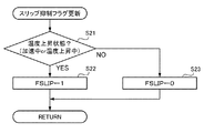
S21では、第1選択還元触媒が温度上昇状態であるか否かを判別し、この判別がYESである場合にはスリップ抑制フラグFSLIPを“1”にセットし(S22)、この判別がNOである場合にはスリップ抑制フラグFSLIPを“0”にリセットする(S23)。ここで、温度上昇状態とは、第1選択還元触媒の温度が現に上昇している状態だけでなく、現在は上昇していないが近いうちに上昇すると考えられる状態も含む。そこで、S21では、第1選択還元触媒の現在の温度TSCRの微分値が所定の正の閾値以上である場合、予測温度TSCR_PREと現在の温度TSCRとの差が所定の正の閾値以上である場合、又はエンジンが加速運転中である場合には、第1選択還元触媒が温度上昇状態であると判別する。 In S21, it is determined whether or not the first selective reduction catalyst is in a temperature rising state. If this determination is YES, the slip suppression flag FSLIP is set to “1” (S22), and this determination is NO. If there is, the slip suppression flag FSLIP is reset to “0” (S23). Here, the temperature rise state includes not only a state where the temperature of the first selective reduction catalyst is actually rising, but also a state where the temperature is not currently rising but is considered to increase soon. Therefore, in S21, when the differential value of the current temperature TSCR of the first selective reduction catalyst is greater than or equal to a predetermined positive threshold, the difference between the predicted temperature TSCR_PRE and the current temperature TSCR is greater than or equal to a predetermined positive threshold. Alternatively, when the engine is accelerating, it is determined that the first selective reduction catalyst is in a temperature rising state.
図15は、S5の加速時遅延フラグFDELを更新する手順を示すフローチャートである。図15に示す処理は、ECUにより所定の制御周期ごとに、図13に示す処理とは別に実行される。エンジンが加速運転状態に移行すると、第1選択還元触媒の温度は、移行時には上昇していなくても、その後追って上昇すると考えられる。また、加速運転状態に移行した直後は、NOxセンサの遅れからユリア噴射量は不足する傾向がある。そこで、図15に示す処理では、スリップ抑制フラグFSLIPが“1”となり、スリップ抑制制御を実行するのに適した時期であると判断されている場合であっても、エンジンが加速運転状態に移行してから所定時間スリップ抑制制御の実行開始を遅延させるべく、この加速時遅延フラグFDELを更新する。すなわち、この加速時遅延フラグFDELは、スリップ抑制制御の実行開始の遅延が要求されている状態であることを示すフラグであり、このフラグFDELが“1”にセットされている間は、図13に示すようにスリップ抑制制御の実行開始は遅延される。 FIG. 15 is a flowchart showing a procedure for updating the acceleration delay flag FDEL in S5. The process shown in FIG. 15 is executed separately from the process shown in FIG. 13 by the ECU every predetermined control cycle. When the engine shifts to the acceleration operation state, the temperature of the first selective reduction catalyst is considered to increase later even if it does not increase during the shift. Further, immediately after shifting to the acceleration operation state, the urea injection amount tends to be insufficient due to the delay of the NOx sensor. Therefore, in the process shown in FIG. 15, even when it is determined that the slip suppression flag FSLIP is “1” and the time is appropriate for executing the slip suppression control, the engine shifts to the acceleration operation state. Then, the acceleration delay flag FDEL is updated to delay the start of the slip suppression control for a predetermined time. In other words, this acceleration delay flag FDEL is a flag indicating that a delay in starting the execution of slip suppression control is requested. While this flag FDEL is set to “1”, FIG. As shown in FIG. 4, the start of the slip suppression control is delayed.
S31では、エンジンが加速運転状態に移行したか否かを判別する。S31の判別がYESである場合には、加速時遅延フラグFDELを“1”にセットし(S32)、遅延タイマの値を所定の初期値にセットし(S33)、S36に移る。S31の判別がNOの場合には、S34に移り、加速時遅延フラグFDELが“1”であるか否かを判別する。S34の判別がNOである場合にはS36に移り、YESである場合にはS33でセットした遅延タイマの値を減算し(S35)、S36に移る。 In S31, it is determined whether or not the engine has shifted to an acceleration operation state. If the determination in S31 is YES, the acceleration delay flag FDEL is set to “1” (S32), the value of the delay timer is set to a predetermined initial value (S33), and the process proceeds to S36. When the determination in S31 is NO, the process proceeds to S34, and it is determined whether or not the acceleration delay flag FDEL is “1”. If the determination in S34 is NO, the process proceeds to S36, and if YES, the value of the delay timer set in S33 is subtracted (S35), and the process proceeds to S36.
S36では、遅延タイマの値が“0”であるか否かを判別する。S36の判別がNOである場合にはこの処理を終了する。S36の判別がYESである場合には、S37に移り、加速時遅延フラグFDELを“0”にリセットした後、この処理を終了する。 In S36, it is determined whether or not the value of the delay timer is “0”. If the determination in S36 is NO, this process ends. If the determination in S36 is YES, the process proceeds to S37, the acceleration delay flag FDEL is reset to “0”, and then this process ends.
図16は、図13のS7に示すスリップ抑制制御(図13のS7)の具体的な手順を示すフローチャートである。図16に示す処理では、スリップ抑制制御からの復帰時におけるNOx浄化性能の低下及び不要な尿素水の消費を抑制するように、第2選択還元触媒の状態に応じてユリア噴射量及びEGR弁の開度を適度に制御する。 FIG. 16 is a flowchart showing a specific procedure of the slip suppression control (S7 in FIG. 13) shown in S7 of FIG. In the process shown in FIG. 16, the urea injection amount and the EGR valve are controlled according to the state of the second selective reduction catalyst so as to suppress the deterioration of the NOx purification performance and the unnecessary consumption of urea water when returning from the slip suppression control. Control the opening appropriately.
S41では、NH3センサの検出値が閾値以上でありかつ第2選択還元触媒のストレージ量の推定値がその目標値より大きいか否かを判別する(VNH3≧VNH3_thかつST2nd>ST2nd_TRGT)。ここで、第2選択還元触媒のストレージ量に対する目標値ST2nd_TRGTは、第2選択還元触媒からのNH3のスリップを確実に抑制できるように、例えば、第2選択還元触媒の最大ストレージ容量の推定値ST2nd_maxよりも十分に小さな値に設定される。 In S41, it is determined whether or not the detected value of the NH 3 sensor is equal to or larger than the threshold value and the estimated value of the storage amount of the second selective reduction catalyst is larger than the target value (VNH3 ≧ VNH3_th and ST2nd> ST2nd_TRGT). Here, the target value ST2nd_TRGT for the storage amount of the second selective reduction catalyst is, for example, an estimated value of the maximum storage capacity of the second selective reduction catalyst so that NH 3 slip from the second selective reduction catalyst can be reliably suppressed. It is set to a value sufficiently smaller than ST2nd_max.
S41の判別がNOである場合、すなわち第2選択還元触媒には、第1選択還元触媒からスリップしたNH3をある程度吸着する余裕があると判断できる場合には、ユリア噴射量を通常制御時(GUREA_ORD)から僅かに制限するのみで第2選択還元触媒からのNH3スリップを抑制できると判断し、S42に移る。S42では、スリップ抑制補正量ΔSTを算出し、S43では、ユリア噴射量を通常噴射量からスリップ抑制補正量だけ制限し(GUREA←GUREA_ORD−ΔST)、図13のS3に移り、EGR弁の開度を通常開度に設定する(VO←VO_ORD)。 If the determination in S41 is NO, that is, if it can be determined that the second selective reduction catalyst has some allowance for adsorbing NH 3 slipped from the first selective reduction catalyst, the urea injection amount is controlled during normal control ( It is determined that NH 3 slip from the second selective reduction catalyst can be suppressed only by slightly limiting from (GUREA_ORD), and the process proceeds to S42. In S42, the slip suppression correction amount ΔST is calculated, and in S43, the urea injection amount is limited from the normal injection amount by the slip suppression correction amount (GUREA ← GUREA_ORD−ΔST), and the process proceeds to S3 in FIG. Is set to the normal opening (VO ← VO_ORD).
S41の判別がNOである場合、すなわち第2選択還元触媒には、第1選択還元触媒からスリップしたNH3を吸着する余裕があまり無いと判断できる場合には、ユリア噴射量を上記スリップ抑制補正量ΔSTよりもさらに多く制限するべく、S45に移る。S45では、第2選択還元触媒のストレージ容量の推定値がその最大ストレージ容量の推定値より小さいか否かを判別する(ST2nd<ST2nd_max)。S45の判別がYESの場合には、S46に移り当量比α=0.5に相当する量までユリア噴射量を制限し(GUREA←GUREA_BS×0.5)、S45の判別がNOの場合には、さらに噴射量を制限するべくS47に移り、当量比α=0.3に相当する量までユリア噴射量を制限する(GUREA←GUREA_BS×0.3)。 If the determination in S41 is NO, that is, if it can be determined that the second selective reduction catalyst does not have much room for adsorbing NH 3 slipped from the first selective reduction catalyst, the urea injection amount is corrected to the slip suppression correction. The process proceeds to S45 in order to limit more than the amount ΔST. In S45, it is determined whether or not the estimated value of the storage capacity of the second selective reduction catalyst is smaller than the estimated value of the maximum storage capacity (ST2nd <ST2nd_max). If the determination in S45 is YES, the process proceeds to S46 and the urea injection amount is limited to an amount corresponding to the equivalence ratio α = 0.5 (GUREA ← GUREA_BS × 0.5), and if the determination in S45 is NO Then, the process proceeds to S47 to further limit the injection amount, and the urea injection amount is limited to an amount corresponding to the equivalence ratio α = 0.3 (GUREA ← GUREA_BS × 0.3).
S48では、NH3スリップ速度がNH3消費速度より速いか否か(V_SLIP>V_RED)を判別する。S48の判別がNOである場合には、エンジンのNOx排出量を増加させずとも第2選択還元触媒からのNH3スリップを抑制できると判断し、図13のS3に移り、EGR弁の開度を通常開度に設定する。S48の判別がYESである場合には、第2選択還元触媒からのNH3スリップを抑制するためには、ユリア噴射量の制限に加え、さらにエンジンからのNOx排出量を増加させる必要があると判断し、S49に移る。S49では、EGR弁の開度を、通常開度よりも閉じ側に補正し(VO←VO_CLO)、この処理を終了する。 In S48, it is determined whether or not the NH 3 slip speed is faster than the NH 3 consumption speed (V_SLIP> V_RED). If the determination in S48 is NO, it is determined that NH 3 slip from the second selective reduction catalyst can be suppressed without increasing the NOx emission amount of the engine, and the process proceeds to S3 in FIG. Is set to the normal opening. If the determination in S48 is YES, in order to suppress the NH 3 slip from the second selective reduction catalyst, it is necessary to further increase the NOx emission amount from the engine in addition to limiting the urea injection amount. Judge and move to S49. In S49, the opening degree of the EGR valve is corrected closer to the closing side than the normal opening degree (VO ← VO_CLO), and this process is terminated.
上記実施形態では、アンモニアを還元剤とし、かつこの前駆体として尿素水を供給する尿素添加式の排気浄化システムに、本発明を適用した例を示したが、これに限るものではない。
例えば、尿素水を供給しこの尿素水からアンモニアを生成せずに、直接アンモニアを供給してもよい。また、アンモニアの前駆体としては、尿素水に限らず他の添加剤を用いてもよい。また、NOxを還元するための還元剤はアンモニアに限るものではない。本発明は、NOxを還元するための還元剤として、アンモニアの代わりに、例えば炭化水素を用いた排気浄化システムに適用することもできる。
In the above embodiment, an example in which the present invention is applied to a urea addition type exhaust gas purification system that uses ammonia as a reducing agent and supplies urea water as a precursor thereof is shown, but the present invention is not limited thereto.
For example, ammonia may be supplied directly without supplying urea water and generating ammonia from the urea water. The ammonia precursor is not limited to urea water, and other additives may be used. Further, the reducing agent for reducing NOx is not limited to ammonia. The present invention can also be applied to an exhaust purification system using, for example, hydrocarbons instead of ammonia as a reducing agent for reducing NOx.
1…エンジン(内燃機関)
11…排気管(排気通路)
12…吸気管(吸気通路)
18…EGR管(EGR通路)
19…EGR弁
2…排気浄化システム
231…第1選択還元触媒
232…第2選択還元触媒
25…ユリア噴射装置(還元剤供給手段)
26…NH3センサ(還元剤検出手段、第2ストレージ量推定手段、第2吸着許容量推定手段)
27…排気温度センサ(温度取得手段)
26…NOxセンサ(流入NOx量取得手段)
3…ECU(温度取得手段、温度上昇判定手段、スリップ抑制制御手段、第2ストレージ量推定手段、目標値設定手段、第2吸着許容量推定手段)
64…スリップ速度算出部(スリップ量推定手段)
1. Engine (internal combustion engine)
11 ... Exhaust pipe (exhaust passage)
12 ... Intake pipe (intake passage)
18 ... EGR pipe (EGR passage)
DESCRIPTION OF
26... NH 3 sensor (reducing agent detection means, second storage amount estimation means, second adsorption allowable amount estimation means)
27. Exhaust temperature sensor (temperature acquisition means)
26 ... NOx sensor (inflow NOx amount acquisition means)
3 ... ECU (temperature acquisition means, temperature rise determination means, slip suppression control means, second storage amount estimation means, target value setting means, second adsorption allowable amount estimation means)
64 ... slip speed calculation section (slip amount estimation means)
Claims (9)
前記排気通路のうち前記第1選択還元触媒より下流側に設けられた第2選択還元触媒と、
前記排気通路のうち前記第1選択還元触媒より上流側に還元剤又はその前駆体を供給する還元剤供給手段と、を備えた内燃機関の排気浄化システムであって、
前記内燃機関の運転状態に基づいて、前記第1選択還元触媒が温度上昇状態であるか否かを判定する温度上昇判定手段と、
当該温度上昇判定手段により温度上昇状態であると判定された場合には、前記還元剤供給手段からの還元剤又は前駆体の供給量を0より大きな制限供給量まで低減させる還元剤制限制御、及び前記内燃機関のNOx排出量を通常制御時より増加させるNOx排出量増加制御のうち、前記還元剤制限制御のみ又は前記還元剤制限制御及び前記NOx排出量増加制御の両方を実行するスリップ抑制制御手段と、
前記第1選択還元触媒からの還元剤スリップ量を推定するスリップ量推定手段と、
前記第1選択還元触媒に流入したNOxを浄化するために当該第1選択還元触媒において消費された還元剤の量に相当する還元剤消費量を推定する還元剤消費量推定手段と、を備え、
前記スリップ抑制制御手段は、前記推定された還元剤スリップ量が前記推定された還元剤消費量より多い場合には前記NOx排出量増加制御を実行し、前記推定された還元剤スリップ量が前記推定された還元剤消費量より少ない場合には前記NOx排出量増加制御を実行しないことを特徴とする内燃機関の排気浄化システム。 A first selective reduction catalyst that is provided in an exhaust passage of the internal combustion engine, purifies NOx in the exhaust in the presence of the reducing agent, and adsorbs the reducing agent;
A second selective reduction catalyst provided downstream of the first selective reduction catalyst in the exhaust passage;
An exhaust gas purification system for an internal combustion engine, comprising: a reducing agent supply means for supplying a reducing agent or a precursor thereof upstream of the first selective reduction catalyst in the exhaust passage,
A temperature increase determination means for determining whether or not the first selective reduction catalyst is in a temperature increase state based on an operating state of the internal combustion engine;
A reducing agent restriction control for reducing the supply amount of the reducing agent or the precursor from the reducing agent supply means to a restriction supply amount greater than 0 when the temperature rise determination means determines that the temperature is in an elevated state; and Slip suppression control means for executing only the reducing agent restriction control or both the reducing agent restriction control and the NOx emission increase control among the NOx emission increase control for increasing the NOx emission amount of the internal combustion engine from the normal control time. When,
Slip amount estimating means for estimating a reducing agent slip amount from the first selective reduction catalyst;
Reducing agent consumption estimation means for estimating a reducing agent consumption corresponding to the amount of reducing agent consumed in the first selective reduction catalyst in order to purify NOx flowing into the first selective reduction catalyst;
The slip suppression control means executes the NOx emission increase control when the estimated reducing agent slip amount is larger than the estimated reducing agent consumption amount, and the estimated reducing agent slip amount is the estimated amount. The exhaust gas purification system for an internal combustion engine, wherein the NOx emission amount increase control is not executed when the amount of the reducing agent consumed is smaller .
前記内燃機関の運転状態に基づいて前記第1選択還元触媒におけるNOx浄化率を推定する第1浄化率推定手段と、
前記第1選択還元触媒の温度を検出又は推定する温度取得手段と、
前記検出又は推定された温度に基づいて、前記第1選択還元触媒における還元剤の吸着許容量を推定する第1吸着許容量推定手段と、備え、
前記還元剤消費量推定手段は、前記還元剤消費量を、前記推定されたNOx浄化率と前記検出又は推定されたNOx量とに基づいて推定し、
前記スリップ量推定手段は、前記推定された第1選択還元触媒の吸着許容量に基づいて、前記第1選択還元触媒からの還元剤スリップ量を推定することを特徴とする請求項1に記載の内燃機関の排気浄化システム。 Inflow NOx amount acquisition means for detecting or estimating the amount of NOx flowing into the first selective reduction catalyst;
First purification rate estimating means for estimating a NOx purification rate in the first selective reduction catalyst based on an operating state of the internal combustion engine;
Temperature acquisition means for detecting or estimating the temperature of the first selective reduction catalyst;
A first adsorption allowable amount estimating means for estimating an adsorption allowable amount of the reducing agent in the first selective reduction catalyst based on the detected or estimated temperature ;
The reducing agent consumption estimation means estimates the reducing agent consumption based on the estimated NOx purification rate and the detected or estimated NOx amount,
2. The slip amount estimating means estimates a reducing agent slip amount from the first selective reduction catalyst based on the estimated adsorption allowable amount of the first selective reduction catalyst . An exhaust purification system for an internal combustion engine.
前記内燃機関の運転状態に基づいて前記第1選択還元触媒におけるNOx浄化率を推定する第1浄化率推定手段と、
前記第1選択還元触媒と前記第2選択還元触媒との間の排気の還元剤濃度を検出する還元剤検出手段と、
前記還元剤消費量推定手段は、前記還元剤消費量を、前記推定されたNOx浄化率と前記検出又は推定されたNOx量とに基づいて推定し、
前記スリップ量推定手段は、前記検出された還元剤濃度に基づいて、前記第1選択還元触媒からの還元剤スリップ量を推定することを特徴とする請求項1に記載の内燃機関の排気浄化システム。 Inflow NOx amount acquisition means for detecting or estimating the amount of NOx flowing into the first selective reduction catalyst;
First purification rate estimating means for estimating a NOx purification rate in the first selective reduction catalyst based on an operating state of the internal combustion engine;
Reducing agent detection means for detecting a reducing agent concentration of exhaust gas between the first selective reduction catalyst and the second selective reduction catalyst;
The reducing agent consumption estimation means estimates the reducing agent consumption based on the estimated NOx purification rate and the detected or estimated NOx amount,
2. The exhaust gas purification system for an internal combustion engine according to claim 1, wherein the slip amount estimating means estimates a reducing agent slip amount from the first selective reduction catalyst based on the detected reducing agent concentration. .
前記排気通路のうち前記第1選択還元触媒より下流側に設けられた第2選択還元触媒と、
前記排気通路のうち前記第1選択還元触媒より上流側に還元剤又はその前駆体を供給する還元剤供給手段と、を備えた内燃機関の排気浄化システムであって、
前記内燃機関の運転状態に基づいて、前記第1選択還元触媒が温度上昇状態であるか否かを判定する温度上昇判定手段と、
当該温度上昇判定手段により温度上昇状態であると判定された場合には、前記還元剤供給手段からの還元剤又は前駆体の供給量を0より大きな制限供給量まで低減させる還元剤制限制御、及び前記内燃機関のNOx排出量を通常制御時より増加させるNOx排出量増加制御のうち、前記還元剤制限制御のみ又は前記還元剤制限制御及び前記NOx排出量増加制御の両方を実行するスリップ抑制制御手段と、
前記内燃機関の運転状態に基づいて前記第2選択還元触媒における還元剤のストレージ量を推定する第2ストレージ量推定手段と、
前記内燃機関の運転状態に基づいて前記第2選択還元触媒のストレージ量の推定値に対する目標値を設定する目標値設定手段と、を備え、
前記スリップ抑制制御手段は、前記第2選択還元触媒のストレージ量の推定値が前記目標値以下である場合には前記還元剤制限制御を実行しかつ前記NOx排出量増加制御を実行しないことを特徴とする内燃機関の排気浄化システム。 A first selective reduction catalyst that is provided in an exhaust passage of the internal combustion engine, purifies NOx in the exhaust in the presence of the reducing agent, and adsorbs the reducing agent;
A second selective reduction catalyst provided downstream of the first selective reduction catalyst in the exhaust passage;
An exhaust gas purification system for an internal combustion engine, comprising: a reducing agent supply means for supplying a reducing agent or a precursor thereof upstream of the first selective reduction catalyst in the exhaust passage,
A temperature increase determination means for determining whether or not the first selective reduction catalyst is in a temperature increase state based on an operating state of the internal combustion engine;
A reducing agent restriction control for reducing the supply amount of the reducing agent or the precursor from the reducing agent supply means to a restriction supply amount greater than 0 when the temperature rise determination means determines that the temperature is in an elevated state; and Slip suppression control means for executing only the reducing agent restriction control or both the reducing agent restriction control and the NOx emission increase control among the NOx emission increase control for increasing the NOx emission amount of the internal combustion engine from the normal control time. When,
Second storage amount estimation means for estimating a storage amount of the reducing agent in the second selective reduction catalyst based on an operating state of the internal combustion engine;
Target value setting means for setting a target value for the estimated value of the storage amount of the second selective reduction catalyst based on the operating state of the internal combustion engine,
The slip suppression control means executes the reducing agent restriction control and does not execute the NOx emission increase control when the estimated value of the storage amount of the second selective reduction catalyst is equal to or less than the target value. An exhaust purification system for an internal combustion engine.
前記排気通路のうち前記第1選択還元触媒より下流側に設けられた第2選択還元触媒と、
前記排気通路のうち前記第1選択還元触媒より上流側に還元剤又はその前駆体を供給する還元剤供給手段と、を備えた内燃機関の排気浄化システムであって、
前記内燃機関の運転状態に基づいて、前記第1選択還元触媒が温度上昇状態であるか否かを判定する温度上昇判定手段と、
当該温度上昇判定手段により温度上昇状態であると判定された場合には、前記還元剤供給手段からの還元剤又は前駆体の供給量を0より大きな制限供給量まで低減させる還元剤制限制御、及び前記内燃機関のNOx排出量を通常制御時より増加させるNOx排出量増加制御のうち、前記還元剤制限制御のみ又は前記還元剤制限制御及び前記NOx排出量増加制御の両方を実行するスリップ抑制制御手段と、
前記内燃機関の運転状態に基づいて、前記第2選択還元触媒における還元剤のストレージ量を推定する第2ストレージ量推定手段と、を備え、
前記スリップ抑制制御手段は、前記第2選択還元触媒のストレージ量に応じて前記制限供給量を変えることを特徴とする内燃機関の排気浄化システム。 A first selective reduction catalyst that is provided in an exhaust passage of the internal combustion engine, purifies NOx in the exhaust in the presence of the reducing agent, and adsorbs the reducing agent;
A second selective reduction catalyst provided downstream of the first selective reduction catalyst in the exhaust passage;
An exhaust gas purification system for an internal combustion engine, comprising: a reducing agent supply means for supplying a reducing agent or a precursor thereof upstream of the first selective reduction catalyst in the exhaust passage,
A temperature increase determination means for determining whether or not the first selective reduction catalyst is in a temperature increase state based on an operating state of the internal combustion engine;
A reducing agent restriction control for reducing the supply amount of the reducing agent or the precursor from the reducing agent supply means to a restriction supply amount greater than 0 when the temperature rise determination means determines that the temperature is in an elevated state; and Slip suppression control means for executing only the reducing agent restriction control or both the reducing agent restriction control and the NOx emission increase control among the NOx emission increase control for increasing the NOx emission amount of the internal combustion engine from the normal control time. When,
Second storage amount estimation means for estimating a storage amount of the reducing agent in the second selective reduction catalyst based on an operating state of the internal combustion engine,
The exhaust purification system for an internal combustion engine, wherein the slip suppression control means changes the limit supply amount according to a storage amount of the second selective reduction catalyst.
前記スリップ抑制制御手段は、前記第2選択還元触媒のストレージ量の推定値が前記吸着許容量の推定値より小さい場合には、当該ストレージ量の推定値が当該吸着許容量の推定値以上である場合よりも、前記制限供給量を多くすることを特徴とする請求項5に記載の内燃機関の排気浄化システム。When the estimated value of the storage amount of the second selective reduction catalyst is smaller than the estimated value of the adsorption allowable amount, the slip suppression control means has an estimated value of the storage amount equal to or larger than the estimated value of the adsorption allowable amount. 6. The exhaust gas purification system for an internal combustion engine according to claim 5, wherein the limited supply amount is increased as compared with the case.
前記排気通路のうち前記第1選択還元触媒より下流側に設けられた第2選択還元触媒と、
前記排気通路のうち前記第1選択還元触媒より上流側に還元剤又はその前駆体を供給する還元剤供給手段と、を備えた内燃機関の排気浄化システムであって、
前記内燃機関の運転状態に基づいて、前記第1選択還元触媒が温度上昇状態であるか否かを判定する温度上昇判定手段と、
当該温度上昇判定手段により温度上昇状態であると判定された場合には、前記還元剤供給手段からの還元剤又は前駆体の供給量を0より大きな制限供給量まで低減させる還元剤制限制御、及び前記内燃機関のNOx排出量を通常制御時より増加させるNOx排出量増加制御のうち、前記還元剤制限制御のみ又は前記還元剤制限制御及び前記NOx排出量増加制御の両方を実行するスリップ抑制制御手段と、
前記内燃機関が加速運転状態に移行したことを判定する加速判定手段と、を備え、
前記スリップ抑制制御手段は、前記加速判定手段により加速運転状態に移行したと判定された場合には、前記還元剤制限制御及び前記NOx排出量増加制御の実行開始を遅延させることを特徴とする内燃機関の排気浄化システム。 A first selective reduction catalyst that is provided in an exhaust passage of the internal combustion engine, purifies NOx in the exhaust in the presence of the reducing agent, and adsorbs the reducing agent;
A second selective reduction catalyst provided downstream of the first selective reduction catalyst in the exhaust passage;
An exhaust gas purification system for an internal combustion engine, comprising: a reducing agent supply means for supplying a reducing agent or a precursor thereof upstream of the first selective reduction catalyst in the exhaust passage,
A temperature increase determination means for determining whether or not the first selective reduction catalyst is in a temperature increase state based on an operating state of the internal combustion engine;
A reducing agent restriction control for reducing the supply amount of the reducing agent or the precursor from the reducing agent supply means to a restriction supply amount greater than 0 when the temperature rise determination means determines that the temperature is in an elevated state; and Slip suppression control means for executing only the reducing agent restriction control or both the reducing agent restriction control and the NOx emission increase control among the NOx emission increase control for increasing the NOx emission amount of the internal combustion engine from the normal control time. When,
Acceleration determination means for determining that the internal combustion engine has shifted to an acceleration operation state,
The internal combustion engine characterized in that the slip suppression control means delays execution of the reducing agent restriction control and the NOx emission increase control when the acceleration determination means determines that the acceleration operation state has been entered. Engine exhaust purification system.
前記排気通路のうち前記第1選択還元触媒より下流側に設けられた第2選択還元触媒と、
前記排気通路のうち前記第1選択還元触媒より上流側に還元剤又はその前駆体を供給する還元剤供給手段と、を備えた内燃機関の排気浄化システムであって、
前記内燃機関の運転状態に基づいて、前記第1選択還元触媒が温度上昇状態であるか否かを判定する温度上昇判定手段と、
当該温度上昇判定手段により温度上昇状態であると判定された場合には、前記還元剤供給手段からの還元剤又は前駆体の供給量を0より大きな制限供給量まで低減させる還元剤制限制御、及び前記内燃機関のNOx排出量を通常制御時より増加させるNOx排出量増加制御のうち、前記還元剤制限制御のみ又は前記還元剤制限制御及び前記NOx排出量増加制御の両方を実行するスリップ抑制制御手段と、
前記第1選択還元触媒と前記第2選択還元触媒の間の排気の還元剤濃度を検出する還元剤濃度検出手段と、を備え、
前記スリップ抑制制御手段は、前記還元剤濃度検出手段の出力値が所定値より小さい場合には、前記還元剤制限制御を実行しかつ前記NOx排出量増加制御を実行しないことを特徴とする内燃機関の排気浄化システム。 A first selective reduction catalyst that is provided in an exhaust passage of the internal combustion engine, purifies NOx in the exhaust in the presence of the reducing agent, and adsorbs the reducing agent;
A second selective reduction catalyst provided downstream of the first selective reduction catalyst in the exhaust passage;
An exhaust gas purification system for an internal combustion engine, comprising: a reducing agent supply means for supplying a reducing agent or a precursor thereof upstream of the first selective reduction catalyst in the exhaust passage,
A temperature increase determination means for determining whether or not the first selective reduction catalyst is in a temperature increase state based on an operating state of the internal combustion engine;
A reducing agent restriction control for reducing the supply amount of the reducing agent or the precursor from the reducing agent supply means to a restriction supply amount greater than 0 when the temperature rise determination means determines that the temperature is in an elevated state; and Slip suppression control means for executing only the reducing agent restriction control or both the reducing agent restriction control and the NOx emission increase control among the NOx emission increase control for increasing the NOx emission amount of the internal combustion engine from the normal control time. When,
Reducing agent concentration detecting means for detecting a reducing agent concentration of exhaust gas between the first selective reduction catalyst and the second selective reduction catalyst;
The internal combustion engine, wherein the slip suppression control means executes the reducing agent restriction control and does not execute the NOx emission increase control when the output value of the reducing agent concentration detection means is smaller than a predetermined value. Exhaust purification system.
前記排気通路のうち前記第1選択還元触媒より下流側に設けられた第2選択還元触媒と、
前記排気通路のうち前記第1選択還元触媒より上流側に還元剤又はその前駆体を供給する還元剤供給手段と、
前記排気通路を流通する排気の一部を、EGRガスとして前記内燃機関の吸気通路に還流するEGR通路と、
前記EGR通路に設けられEGRガスの量を制御するEGR弁と、を備えた内燃機関の排気浄化システムであって、
前記内燃機関の運転状態に基づいて、前記第1選択還元触媒が温度上昇状態であるか否かを判定する温度上昇判定手段と、
当該温度上昇判定手段により温度上昇状態であると判定された場合には、前記還元剤供給手段からの還元剤又は前駆体の供給量を0より大きな制限供給量まで低減させる還元剤制限制御、及び前記内燃機関のNOx排出量を通常制御時より増加させるNOx排出量増加制御のうち、前記還元剤制限制御のみ又は前記還元剤制限制御及び前記NOx排出量増加制御の両方を実行するスリップ抑制制御手段と、
前記第1選択還元触媒からの還元剤スリップ量を推定するスリップ量推定手段と、
前記第1選択還元触媒に流入したNOxを浄化するために当該第1選択還元触媒において消費された還元剤の量に相当する還元剤消費量を推定する還元剤消費量推定手段と、を備え、
前記NOx排出量増加制御では、前記EGR弁の開度を通常制御時における開度より閉じ側に補正することでNOx排出量を増加させ、
前記スリップ抑制制御手段は、前記推定された還元剤スリップ量と前記推定された還元剤消費量との偏差に基づいて、前記EGR弁の開度の通常制御時における開度からの補正量を決定することを特徴とする内燃機関の排気浄化システム。 A first selective reduction catalyst that is provided in an exhaust passage of the internal combustion engine, purifies NOx in the exhaust in the presence of the reducing agent, and adsorbs the reducing agent;
A second selective reduction catalyst provided downstream of the first selective reduction catalyst in the exhaust passage;
Reducing agent supply means for supplying a reducing agent or a precursor thereof upstream of the first selective reduction catalyst in the exhaust passage;
An EGR passage that recirculates a part of the exhaust gas flowing through the exhaust passage as EGR gas to the intake passage of the internal combustion engine;
An exhaust gas purification system for an internal combustion engine comprising an EGR valve provided in the EGR passage for controlling the amount of EGR gas ,
A temperature increase determination means for determining whether or not the first selective reduction catalyst is in a temperature increase state based on an operating state of the internal combustion engine;
A reducing agent restriction control for reducing the supply amount of the reducing agent or the precursor from the reducing agent supply means to a restriction supply amount greater than 0 when the temperature rise determination means determines that the temperature is in an elevated state; and Slip suppression control means for executing only the reducing agent restriction control or both the reducing agent restriction control and the NOx emission increase control among the NOx emission increase control for increasing the NOx emission amount of the internal combustion engine from the normal control time. When,
Slip amount estimating means for estimating a reducing agent slip amount from the first selective reduction catalyst;
Reducing agent consumption estimation means for estimating a reducing agent consumption corresponding to the amount of reducing agent consumed in the first selective reduction catalyst in order to purify NOx flowing into the first selective reduction catalyst;
In the NOx emission amount increase control, the NOx emission amount is increased by correcting the opening degree of the EGR valve to the closed side from the opening degree in the normal control,
The slip suppression control means determines a correction amount from an opening degree during normal control of the opening degree of the EGR valve, based on a deviation between the estimated reducing agent slip amount and the estimated reducing agent consumption amount. An exhaust gas purification system for an internal combustion engine.
Priority Applications (1)
| Application Number | Priority Date | Filing Date | Title |
|---|---|---|---|
| JP2011081977A JP5837319B2 (en) | 2011-04-01 | 2011-04-01 | Exhaust gas purification system for internal combustion engine |
Applications Claiming Priority (1)
| Application Number | Priority Date | Filing Date | Title |
|---|---|---|---|
| JP2011081977A JP5837319B2 (en) | 2011-04-01 | 2011-04-01 | Exhaust gas purification system for internal combustion engine |
Publications (3)
| Publication Number | Publication Date |
|---|---|
| JP2012215154A JP2012215154A (en) | 2012-11-08 |
| JP2012215154A5 JP2012215154A5 (en) | 2014-03-27 |
| JP5837319B2 true JP5837319B2 (en) | 2015-12-24 |
Family
ID=47268107
Family Applications (1)
| Application Number | Title | Priority Date | Filing Date |
|---|---|---|---|
| JP2011081977A Expired - Fee Related JP5837319B2 (en) | 2011-04-01 | 2011-04-01 | Exhaust gas purification system for internal combustion engine |
Country Status (1)
| Country | Link |
|---|---|
| JP (1) | JP5837319B2 (en) |
Families Citing this family (6)
| Publication number | Priority date | Publication date | Assignee | Title |
|---|---|---|---|---|
| US9097163B2 (en) * | 2012-11-30 | 2015-08-04 | Corning Incorporated | Method, apparatus, and system to control selective catalytic reduction (SCR) catalyst ammonia slip during high temperature transitions |
| JP6430690B2 (en) * | 2013-05-23 | 2018-11-28 | ダイムラー・アクチェンゲゼルシャフトDaimler AG | Exhaust gas purification device for hybrid vehicle |
| JP5962631B2 (en) * | 2013-11-14 | 2016-08-03 | トヨタ自動車株式会社 | Exhaust gas purification device for internal combustion engine |
| JP5915623B2 (en) | 2013-11-14 | 2016-05-11 | トヨタ自動車株式会社 | Exhaust gas purification system for internal combustion engine |
| FR3029571A3 (en) * | 2014-12-09 | 2016-06-10 | Renault Sa | METHOD FOR CONTROLLING A MOTORIZATION DEVICE AND ASSOCIATED MOTORIZATION DEVICE |
| JP7262705B2 (en) * | 2019-09-25 | 2023-04-24 | マツダ株式会社 | engine exhaust purification device |
Family Cites Families (3)
| Publication number | Priority date | Publication date | Assignee | Title |
|---|---|---|---|---|
| JP4542455B2 (en) * | 2005-03-28 | 2010-09-15 | 三菱ふそうトラック・バス株式会社 | Exhaust gas purification device for internal combustion engine |
| WO2010067805A1 (en) * | 2008-12-08 | 2010-06-17 | 三菱重工業株式会社 | Exhaust gas purifying device |
| EP2375022A4 (en) * | 2009-01-07 | 2016-01-06 | Toyota Motor Co Ltd | Exhaust gas purifying apparatus for internal combustion engine |
-
2011
- 2011-04-01 JP JP2011081977A patent/JP5837319B2/en not_active Expired - Fee Related
Also Published As
| Publication number | Publication date |
|---|---|
| JP2012215154A (en) | 2012-11-08 |
Similar Documents
| Publication | Publication Date | Title |
|---|---|---|
| JP5221647B2 (en) | Exhaust gas purification device for internal combustion engine | |
| JP4875744B2 (en) | Catalyst degradation judgment device for exhaust purification system | |
| JP5284408B2 (en) | Exhaust gas purification system for internal combustion engine | |
| JP5259653B2 (en) | Exhaust gas purification system for internal combustion engine | |
| JP5837319B2 (en) | Exhaust gas purification system for internal combustion engine | |
| JP5843699B2 (en) | Exhaust gas purification system for internal combustion engine | |
| JP5738249B2 (en) | Exhaust gas purification system for internal combustion engine | |
| JP5910759B2 (en) | Exhaust gas purification system for internal combustion engine | |
| JP2008121530A (en) | Air-fuel ratio control device of engine | |
| JP5194590B2 (en) | Engine exhaust purification system | |
| JP5918096B2 (en) | Exhaust gas purification system for internal combustion engine | |
| JP3988518B2 (en) | Exhaust gas purification device for internal combustion engine | |
| JP2012052510A (en) | Exhaust emission control system of internal combustion engine | |
| JP5198520B2 (en) | Exhaust gas purification system for internal combustion engine | |
| JP5837312B2 (en) | Exhaust gas purification system for internal combustion engine | |
| JP6087799B2 (en) | Exhaust gas purification system for internal combustion engine | |
| JP5108064B2 (en) | Exhaust gas purification system for internal combustion engine | |
| JP5442551B2 (en) | Catalyst temperature prediction device | |
| JP6254691B2 (en) | Exhaust gas purification system for internal combustion engine | |
| WO2022181641A1 (en) | Hydrocarbon deposition amount estimation device, hydrocarbon deposition amount estimation method, control device, and exhaust gas purification system | |
| JP5157507B2 (en) | Exhaust gas purification system for internal combustion engine | |
| JP5091988B2 (en) | Exhaust gas purification system for internal combustion engine | |
| JP2009299597A (en) | Exhaust emission control device for vehicular internal combustion engine | |
| JP2014088826A (en) | Exhaust cleaning system of internal combustion engine | |
| JP5679839B2 (en) | Air-fuel ratio control device |
Legal Events
| Date | Code | Title | Description |
|---|---|---|---|
| A621 | Written request for application examination |
Free format text: JAPANESE INTERMEDIATE CODE: A621 Effective date: 20131128 |
|
| A521 | Written amendment |
Free format text: JAPANESE INTERMEDIATE CODE: A523 Effective date: 20140207 |
|
| A977 | Report on retrieval |
Free format text: JAPANESE INTERMEDIATE CODE: A971007 Effective date: 20141226 |
|
| A131 | Notification of reasons for refusal |
Free format text: JAPANESE INTERMEDIATE CODE: A131 Effective date: 20150113 |
|
| A521 | Written amendment |
Free format text: JAPANESE INTERMEDIATE CODE: A523 Effective date: 20150316 |
|
| TRDD | Decision of grant or rejection written | ||
| A01 | Written decision to grant a patent or to grant a registration (utility model) |
Free format text: JAPANESE INTERMEDIATE CODE: A01 Effective date: 20151006 |
|
| A61 | First payment of annual fees (during grant procedure) |
Free format text: JAPANESE INTERMEDIATE CODE: A61 Effective date: 20151105 |
|
| R150 | Certificate of patent or registration of utility model |
Ref document number: 5837319 Country of ref document: JP Free format text: JAPANESE INTERMEDIATE CODE: R150 |
|
| LAPS | Cancellation because of no payment of annual fees |