JP5837036B2 - Method and apparatus for expanding the dimming range of a solid state lighting fixture - Google Patents
Method and apparatus for expanding the dimming range of a solid state lighting fixture Download PDFInfo
- Publication number
- JP5837036B2 JP5837036B2 JP2013500621A JP2013500621A JP5837036B2 JP 5837036 B2 JP5837036 B2 JP 5837036B2 JP 2013500621 A JP2013500621 A JP 2013500621A JP 2013500621 A JP2013500621 A JP 2013500621A JP 5837036 B2 JP5837036 B2 JP 5837036B2
- Authority
- JP
- Japan
- Prior art keywords
- phase angle
- control signal
- dimmer
- power control
- power
- Prior art date
- Legal status (The legal status is an assumption and is not a legal conclusion. Google has not performed a legal analysis and makes no representation as to the accuracy of the status listed.)
- Active
Links
- 238000000034 method Methods 0.000 title claims description 36
- 239000007787 solid Substances 0.000 title claims description 15
- 238000001514 detection method Methods 0.000 claims description 39
- 238000006243 chemical reaction Methods 0.000 claims description 14
- 239000003990 capacitor Substances 0.000 claims description 11
- 230000007423 decrease Effects 0.000 claims description 10
- 230000004044 response Effects 0.000 claims description 8
- 238000012886 linear function Methods 0.000 claims description 5
- 238000005070 sampling Methods 0.000 claims description 4
- 230000001629 suppression Effects 0.000 claims description 3
- 230000006870 function Effects 0.000 description 22
- 230000005855 radiation Effects 0.000 description 11
- 238000005286 illumination Methods 0.000 description 10
- 238000001228 spectrum Methods 0.000 description 10
- 238000010586 diagram Methods 0.000 description 9
- 230000008901 benefit Effects 0.000 description 8
- 230000000630 rising effect Effects 0.000 description 8
- 238000005516 engineering process Methods 0.000 description 5
- 239000000463 material Substances 0.000 description 5
- 230000008859 change Effects 0.000 description 4
- 238000013461 design Methods 0.000 description 4
- 238000004020 luminiscence type Methods 0.000 description 4
- OAICVXFJPJFONN-UHFFFAOYSA-N Phosphorus Chemical compound [P] OAICVXFJPJFONN-UHFFFAOYSA-N 0.000 description 3
- 238000005401 electroluminescence Methods 0.000 description 3
- 230000004907 flux Effects 0.000 description 3
- 229910052736 halogen Inorganic materials 0.000 description 3
- 150000002367 halogens Chemical class 0.000 description 3
- 230000003287 optical effect Effects 0.000 description 3
- 238000013519 translation Methods 0.000 description 3
- 238000001429 visible spectrum Methods 0.000 description 3
- 230000009471 action Effects 0.000 description 2
- 238000012937 correction Methods 0.000 description 2
- 230000000694 effects Effects 0.000 description 2
- 229920000642 polymer Polymers 0.000 description 2
- 230000009467 reduction Effects 0.000 description 2
- 239000004065 semiconductor Substances 0.000 description 2
- OKTJSMMVPCPJKN-UHFFFAOYSA-N Carbon Chemical compound [C] OKTJSMMVPCPJKN-UHFFFAOYSA-N 0.000 description 1
- DGAQECJNVWCQMB-PUAWFVPOSA-M Ilexoside XXIX Chemical compound C[C@@H]1CC[C@@]2(CC[C@@]3(C(=CC[C@H]4[C@]3(CC[C@@H]5[C@@]4(CC[C@@H](C5(C)C)OS(=O)(=O)[O-])C)C)[C@@H]2[C@]1(C)O)C)C(=O)O[C@H]6[C@@H]([C@H]([C@@H]([C@H](O6)CO)O)O)O.[Na+] DGAQECJNVWCQMB-PUAWFVPOSA-M 0.000 description 1
- ZLMJMSJWJFRBEC-UHFFFAOYSA-N Potassium Chemical compound [K] ZLMJMSJWJFRBEC-UHFFFAOYSA-N 0.000 description 1
- 238000003491 array Methods 0.000 description 1
- 230000009286 beneficial effect Effects 0.000 description 1
- 229910052799 carbon Inorganic materials 0.000 description 1
- 238000005136 cathodoluminescence Methods 0.000 description 1
- 239000003086 colorant Substances 0.000 description 1
- 238000004891 communication Methods 0.000 description 1
- 238000004590 computer program Methods 0.000 description 1
- 230000008878 coupling Effects 0.000 description 1
- 238000010168 coupling process Methods 0.000 description 1
- 238000005859 coupling reaction Methods 0.000 description 1
- 238000005170 crystalloluminescence Methods 0.000 description 1
- 230000001955 cumulated effect Effects 0.000 description 1
- 230000006837 decompression Effects 0.000 description 1
- 230000003247 decreasing effect Effects 0.000 description 1
- 238000009792 diffusion process Methods 0.000 description 1
- 238000002845 discoloration Methods 0.000 description 1
- 230000005670 electromagnetic radiation Effects 0.000 description 1
- 238000001914 filtration Methods 0.000 description 1
- BHEPBYXIRTUNPN-UHFFFAOYSA-N hydridophosphorus(.) (triplet) Chemical compound [PH] BHEPBYXIRTUNPN-UHFFFAOYSA-N 0.000 description 1
- 230000006872 improvement Effects 0.000 description 1
- 238000002329 infrared spectrum Methods 0.000 description 1
- 238000002347 injection Methods 0.000 description 1
- 239000007924 injection Substances 0.000 description 1
- QSHDDOUJBYECFT-UHFFFAOYSA-N mercury Chemical compound [Hg] QSHDDOUJBYECFT-UHFFFAOYSA-N 0.000 description 1
- 229910001507 metal halide Inorganic materials 0.000 description 1
- 150000005309 metal halides Chemical class 0.000 description 1
- 238000004377 microelectronic Methods 0.000 description 1
- 239000000203 mixture Substances 0.000 description 1
- 230000004048 modification Effects 0.000 description 1
- 238000012986 modification Methods 0.000 description 1
- 230000007935 neutral effect Effects 0.000 description 1
- 238000005424 photoluminescence Methods 0.000 description 1
- 229910052700 potassium Inorganic materials 0.000 description 1
- 239000011591 potassium Substances 0.000 description 1
- 230000008569 process Effects 0.000 description 1
- 238000012545 processing Methods 0.000 description 1
- 235000019553 satiation Nutrition 0.000 description 1
- 229910052708 sodium Inorganic materials 0.000 description 1
- 239000011734 sodium Substances 0.000 description 1
- 238000000904 thermoluminescence Methods 0.000 description 1
- 238000002211 ultraviolet spectrum Methods 0.000 description 1
Images


Classifications
-
- H—ELECTRICITY
- H05—ELECTRIC TECHNIQUES NOT OTHERWISE PROVIDED FOR
- H05B—ELECTRIC HEATING; ELECTRIC LIGHT SOURCES NOT OTHERWISE PROVIDED FOR; CIRCUIT ARRANGEMENTS FOR ELECTRIC LIGHT SOURCES, IN GENERAL
- H05B45/00—Circuit arrangements for operating light-emitting diodes [LED]
- H05B45/30—Driver circuits
- H05B45/37—Converter circuits
- H05B45/3725—Switched mode power supply [SMPS]
-
- H—ELECTRICITY
- H05—ELECTRIC TECHNIQUES NOT OTHERWISE PROVIDED FOR
- H05B—ELECTRIC HEATING; ELECTRIC LIGHT SOURCES NOT OTHERWISE PROVIDED FOR; CIRCUIT ARRANGEMENTS FOR ELECTRIC LIGHT SOURCES, IN GENERAL
- H05B45/00—Circuit arrangements for operating light-emitting diodes [LED]
- H05B45/10—Controlling the intensity of the light
Landscapes
- Circuit Arrangement For Electric Light Sources In General (AREA)
Description
本発明は、一般に、ソリッドステート形照明器具の制御に関する。特に、本明細書において開示する種々の本発明の方法及び装置は、調光器位相角検出に基づいて決定された電力制御信号を用いてソリッドステート形照明器具の調光範囲を選択的に増大させることに関する。 The present invention relates generally to control of solid state lighting fixtures. In particular, the various inventive methods and apparatus disclosed herein selectively increase the dimming range of a solid-state luminaire using a power control signal determined based on dimmer phase angle detection. Related to
ディジタル又はソリッドステート形照明技術、即ち、半導体光源、例えば発光ダイオード(LED)を利用したイルミネーションは、伝統的な蛍光灯、高輝度放電(HID)灯及び白熱灯の実行可能な代替手段を提供する。LEDの機能的な利点及び利益としては、エネルギー変換効率や光学効率が高いこと、耐久性があること、経常費が安いこと、その他多くの利点及び利益が挙げられる。LED技術における最近の技術進歩により、多くの用途において種々の照明効果を実現することができる高効率且つ頑丈なフルスペクトル照明源が提供されている。これら照明源を具体化した照明器具の中には、白色光及び/又は光の種々の色、例えば、赤色、緑色及び青色を生じさせることができる1つ又は2つ以上のLEDを含む照明モジュール並びに例えば米国特許第6,016,038号明細書及び同第6,211,626号明細書に詳細に説明されているように種々の色及び変色照明効果を生じさせることができるようにするためにLEDの出力を別個独立に制御するコントローラ又はプロセッサを有するものがある。なお、これら米国特許を参照により引用し、これらの記載内容を本明細書の一部とする。LED技術としては、線間電圧電力供給白色照明器具、例えばフィリップス・カラー・キネティックス(Philips Color Kinetics)社から入手できるESSENTIALWHITEシリーズが挙げられる。これら照明器具は、立下り区間形調光器技術、例えば120VAC線間電圧について電気低電圧(ELV)型調光器を用いて調光可能である。 Digital or solid-state lighting technology, i.e. illumination using semiconductor light sources such as light emitting diodes (LEDs), provides a viable alternative to traditional fluorescent, high intensity discharge (HID) and incandescent lamps. . Functional advantages and benefits of LEDs include high energy conversion efficiency and optical efficiency, durability, low current costs, and many other benefits and benefits. Recent technological advances in LED technology have provided high-efficiency and rugged full-spectrum illumination sources that can achieve various lighting effects in many applications. Among the luminaires embodying these illumination sources, an illumination module comprising one or more LEDs capable of producing white light and / or various colors of light, e.g. red, green and blue And to be able to produce various color and discoloration lighting effects as described in detail, for example, in US Pat. Nos. 6,016,038 and 6,211,626. Some have a controller or processor that independently controls the output of the LED. In addition, these US patents are cited by reference, and the description thereof is made a part of this specification. LED technology includes line voltage powered white luminaires, such as the ESSENTIALWHITE series available from Philips Color Kinetics. These luminaires can be dimmed using falling section dimmer technology, for example, 120VAC line voltage, using an electrical low voltage (ELV) dimmer.
多くの照明用途は、調光器(調光装置と称される場合もある)を利用している。従来型調光器は、白熱灯(バルブランプ及びハロゲンランプ)について良好に働く。しかしながら、他形式の電子式ランプでは問題が生じ、かかる電子式ランプとしては、コンパクト形蛍光灯(CFL)、電子回路用変成器を用いた低電圧ハロゲンランプ、ソリッドステート形照明(SSL)ランプ、例えばLEDやOLEDが挙げられる。特に、電子回路用変成器を利用した低電圧SSLユニットは、専用の調光器、例えば電子式低電圧(ELV)形調光器又は抵抗‐容量(RC)形調光器を用いて調光可能であり、かかる調光器は、入力のところに力率補正(PFC)回路を有する負荷で適切に働く。 Many lighting applications utilize dimmers (sometimes referred to as dimmers). Conventional dimmers work well for incandescent lamps (bulb lamps and halogen lamps). However, problems arise with other types of electronic lamps, such as compact fluorescent lamps (CFL), low-voltage halogen lamps using electronic circuit transformers, solid-state lighting (SSL) lamps, For example, LED and OLED are mentioned. In particular, a low voltage SSL unit using an electronic circuit transformer is dimmed using a dedicated dimmer such as an electronic low voltage (ELV) dimmer or a resistance-capacitance (RC) dimmer. Yes, such dimmers work well with loads that have a power factor correction (PFC) circuit at the input.
従来型調光器は、典型的には、電源電圧信号の各波形(正弦波)を裁断し、そしてこの波形の残りを照明器具に送る。立上り区間形又はフォワードフェーズ形調光器は、電圧信号波形の立上り区間を裁断する。立下り区間形又はリバースフェーズ形調光器は、電圧信号波形の立下り区間を裁断する。電子負荷、例えばLED駆動装置は、典型的には、立下り区間形調光器について良好に動作する。 Conventional dimmers typically cut each waveform (sine wave) of the power supply voltage signal and send the remainder of this waveform to the luminaire. The rising section type or forward phase type dimmer cuts the rising section of the voltage signal waveform. The falling section type or reverse phase type dimmer cuts the falling section of the voltage signal waveform. Electronic loads, such as LED drivers, typically work well for falling section dimmers.
白熱照明器具及び他の従来型抵抗型照明器具は、位相裁断調光器により生じる裁断正弦波にエラーなく自然に応答する。これとは対照的に。LED及び他のソリッドステート形照明負荷は、かかる位相裁断調光器上に配置された場合、多くの問題、例えば、ローエンドドロップアウト、トライアック失弧、最小負荷問題、ハイエンドフリッカ及び光出力の大きなステップを生じさせる場合がある。加うるに、調光器がその最も低い設定値の状態にあるときにソリッドステート形照明負荷により出力される最小光は、比較的高い。例えば、LEDの低調光器設定光出力は、最大設定光出力の15〜30パーセントである場合があり、これは、低設定値では望ましくないほど高い光出力である。高い光出力は、人間の目の応答が低い光レベルでは極めて敏感であるということによって一層悪化し、光出力が更に高くなるように思われるようになる。かくして、対応の調光器が低設定値に設定されている場合、ソリッドステート形照明負荷により出力される光を減少させる要望が存在する。 Incandescent luminaires and other conventional resistive luminaires naturally respond without error to the chopped sine wave produced by the phase cut dimmer. In contrast to this. LEDs and other solid-state lighting loads have many problems when placed on such phase-cut dimmers, such as low-end dropout, triac misfire, minimum load problems, high-end flicker and large steps in light output May occur. In addition, the minimum light output by the solid state lighting load when the dimmer is in its lowest set point state is relatively high. For example, the LED dimmer set light output may be 15-30 percent of the maximum set light output, which is an undesirably high light output at low set values. High light output is exacerbated by the fact that the response of the human eye is very sensitive at low light levels, and the light output appears to be even higher. Thus, there is a desire to reduce the light output by a solid state lighting load when the corresponding dimmer is set to a low set value.
本発明は、調光器の位相角又は調光レベルが低設定値に設定されている場合、ソリッドステート形照明負荷により出力される光を減少させる本発明の方法及び装置に関する。一般に、一観点では、調光器により制御されるソリッドステート形照明負荷によって出力される光出力レベルを制御するシステムが位相角検出器及び電力変換装置を有する。位相角検出器は、調光器からの整流電圧に基づいて調光器の位相角を検出すると共に検出位相角と所定の第1のしきい値の比較に基づいて電力制御信号を決定するよう構成されている。電力変換装置は、出力電圧をソリッドステート形照明負荷に与えるよう構成され、電力変換装置は、検出位相角が第1のしきい値よりも大きい場合に調光器からの整流電圧に基づいて開ループモードで動作し、検出位相角が第1のしきい値よりも小さい場合に調光器からの整流電圧及び位相角検出回路からの決定済み電力制御信号に基づいて閉ループモードで動作する。 The present invention relates to the method and apparatus of the present invention for reducing the light output by a solid state lighting load when the phase angle or dimming level of the dimmer is set to a low set value. In general, in one aspect, a system for controlling the light output level output by a solid-state lighting load controlled by a dimmer includes a phase angle detector and a power converter. The phase angle detector detects the phase angle of the dimmer based on the rectified voltage from the dimmer and determines the power control signal based on a comparison between the detected phase angle and a predetermined first threshold value. It is configured. The power converter is configured to provide an output voltage to the solid-state lighting load, and the power converter is opened based on the rectified voltage from the dimmer when the detected phase angle is greater than the first threshold. It operates in the loop mode and operates in the closed loop mode based on the rectified voltage from the dimmer and the determined power control signal from the phase angle detection circuit when the detected phase angle is smaller than the first threshold value.
別の観点では、電力抑制方法が調光器に接続された電力コントローラを介してソリッドステート形照明負荷によって出力される光出力レベルを制御する。この方法は、調光器のところで設定された調光レベルに対応する調光器の位相角を検出ステップと、検出位相角が第1の調光しきい値よりも大きい場合、第1の固定電力設定値を有する電力制御信号を発生させ、調光器によって出力された電圧の大きさに基づいてSSL負荷の光出力レベルを調整するステップと、検出位相角が第1の調光しきい値よりも小さい場合、検出位相角の関数として決定された電力設定値を有する電力制御信号を発生させ、調光器によって出力された電圧の大きさ及び所定の電力設定値に基づいてソリッドステート形照明負荷の光出力レベルを調整するステップとを有する。 In another aspect, the power suppression method controls the light output level output by the solid state lighting load via a power controller connected to the dimmer. The method includes a step of detecting a phase angle of the dimmer corresponding to the dimming level set at the dimmer, and a first fixed when the detected phase angle is larger than the first dimming threshold value. Generating a power control signal having a power setpoint and adjusting the light output level of the SSL load based on the magnitude of the voltage output by the dimmer; and a detected phase angle of the first dimming threshold A power control signal having a power set value determined as a function of the detected phase angle, and a solid-state illumination based on the magnitude of the voltage output by the dimmer and the predetermined power set value Adjusting the light output level of the load.
別の観点では、LED負荷、位相角検出回路及び電力変換装置を有する装置が提供される。LED負荷は、調光器の位相角に応答する光出力を備えている。位相角検出回路は、調光器位相角を検出し、PWM電力制御信号をPWM出力から出力するよう構成されており、PWM電力制御信号は、検出された調光器位相角に基づいて決定されたデューティサイクルを有する。電力変換装置は、調光器からの整流電圧及び位相角検出回路からのPWM電力制御信号を受け取り、出力電圧をLED負荷に与えるよう構成されている。位相角検出回路は、検出位相角が高いしきい値を超えている場合、PWM電力制御信号のデューティサイクルを固定された高い百分率に設定し、電力変換装置が整流電圧の大きさに基づいて出力電圧を決定する。位相角検出回路は、検出位相角が高いしきい値よりも小さい場合、PWM電力制御信号のデューティサイクルを検出位相角の所定の関数として計算された可変百分率に設定し、電力変換装置が整流電圧の大きさに加えて、PWM電力制御信号に基づいて出力電圧を決定する。 In another aspect, an apparatus is provided that includes an LED load, a phase angle detection circuit, and a power converter. The LED load has a light output that is responsive to the phase angle of the dimmer. The phase angle detection circuit is configured to detect a dimmer phase angle and output a PWM power control signal from the PWM output, and the PWM power control signal is determined based on the detected dimmer phase angle. Have a different duty cycle. The power converter is configured to receive a rectified voltage from the dimmer and a PWM power control signal from the phase angle detection circuit, and to provide an output voltage to the LED load. The phase angle detection circuit sets the duty cycle of the PWM power control signal to a fixed high percentage when the detected phase angle exceeds a high threshold, and the power converter outputs based on the magnitude of the rectified voltage Determine the voltage. The phase angle detection circuit sets the duty cycle of the PWM power control signal to a variable percentage calculated as a predetermined function of the detection phase angle when the detection phase angle is smaller than a high threshold value, and the power conversion device The output voltage is determined based on the PWM power control signal.
本発明の目的上、本明細書に用いられる「LED」という用語は、任意のエレクトロルミネッセンスダイオード又は電気信号に応答して放射線を発生させることができる他形式のキャリヤ注入/接合利用システムを含むものと理解されるべきである。かくして、LEDという用語は、電流に応答して光を放出する種々の半導体型構造体、光放出ポリマー、有機発光ダイオード(OLED)、エレクトロルミネッセンスストリップ等を含むが、これらには限定されない。特に、LEDという用語は、赤外線スペクトル、紫外線スペクトル及び種々の可視光スペクトルの部分(一般に、約400ナノメートルから約700ナノメートルまでの放射線波長を含む)のうちの1つ又は2つ以上の放射線を発生させるよう構成されているあらゆる形式の発光ダイオード(半導体及び有機発光ダイオードを含む)を意味している。LEDの幾つかの例としては、種々の形式の赤外線LED、紫外線LED、赤色LED、青色LED、緑色LED、黄色LED、琥珀(アンバー)色LED、橙色LED及び白色LED(以下に更に説明する)が挙げられるが、これらには限定されない。また、LEDは、所与のスペクトルの場合(例えば、狭い帯域幅、広い帯域幅)種々の帯域幅(例えば、半値全幅、即ちFWHM)及び所与の一般的色分類(general color categorization)内の様々な主波長を有する放射線を発生させるよう構成されると共に/或いは制御されるのが良いことが理解されるべきである。 For the purposes of this invention, the term “LED” as used herein includes any electroluminescent diode or other type of carrier injection / junction utilization system capable of generating radiation in response to an electrical signal. Should be understood. Thus, the term LED includes, but is not limited to, various semiconductor-type structures that emit light in response to electrical current, light emitting polymers, organic light emitting diodes (OLEDs), electroluminescent strips, and the like. In particular, the term LED refers to one or more radiations in the infrared spectrum, ultraviolet spectrum, and various visible light spectrum portions (generally including radiation wavelengths from about 400 nanometers to about 700 nanometers). Means any type of light emitting diode (including semiconductors and organic light emitting diodes) that is configured to generate Some examples of LEDs include various types of infrared LEDs, ultraviolet LEDs, red LEDs, blue LEDs, green LEDs, yellow LEDs, amber LEDs, orange LEDs, and white LEDs (described further below). However, it is not limited to these. Also, LEDs can be used for a given spectrum (eg, narrow bandwidth, wide bandwidth) in various bandwidths (eg, full width at half maximum or FWHM) and within a given general color categorization. It should be understood that it may be configured and / or controlled to generate radiation having various dominant wavelengths.
例えば、本質的に白色光を発生させるよう構成されたLED(例えば、LED白色照明器具)の一具体化例は、本質的に白色光生じさせるよう組み合わせ状態で混色するエレクトロルミネッセンスの種々のスペクトルをそれぞれ放出する多くのダイ(die)を含む場合がある。別の具体化例では、LED白色照明器具は、第1のスペクトルを有するエレクトロルミネッセンスを別の第2のスペクトルに変換する蛍光物質を関連する場合がある。この具体化例の一実施例では、比較的短い波長及び狭い帯域幅スペクトルを有するエレクトロルミネッセンスは、蛍光物質を「ポンピング」し、かかる蛍光物質は、幾分広いスペクトルを有する長い波長の放射線を放射する。 For example, one embodiment of an LED configured to generate essentially white light (eg, an LED white luminaire) may produce various spectra of electroluminescence that mix in combination to produce essentially white light. May contain many dies that each emit. In another embodiment, the LED white luminaire may involve a phosphor that converts electroluminescence having a first spectrum to another second spectrum. In one embodiment of this embodiment, electroluminescence having a relatively short wavelength and a narrow bandwidth spectrum “pumps” the phosphor, which emits long wavelength radiation having a somewhat broad spectrum. To do.
また、LEDという用語は、LEDの物理的及び/又は電気的パッケージのタイプを制限しないということは理解されるべきである。例えば、上述したように、LEDは、放射線の種々のスペクトルをそれぞれ放出するよう構成された多数のダイ(例えば、個々に制御可能であっても良く又はそうでなくても良い)を有する単一の発光デバイスを意味する場合がある。また、LEDは、LEDの一体部分と考えられる蛍光体と関連する場合がある(例えば、幾つかの形式の白色LED)。一般に、LEDという用語は、パッケージ化LED、非パッケージ化LED、表面実装LED、チップオンボードLED、Tパッケージ実装LED、ラジアルパッケージLED、電力パッケージLED、或る形式のケース及び/又は光学素子(例えば、拡散レンズ)を含むLED等を意味する場合がある。 It should also be understood that the term LED does not limit the physical and / or electrical package type of the LED. For example, as described above, an LED is a single having multiple dies (eg, which may or may not be individually controllable) each configured to emit a different spectrum of radiation. May mean a light emitting device. An LED may also be associated with a phosphor that is considered an integral part of the LED (eg, some types of white LEDs). In general, the term LED refers to packaged LEDs, unpackaged LEDs, surface mount LEDs, chip on board LEDs, T package mount LEDs, radial package LEDs, power package LEDs, some types of cases and / or optical elements (e.g. , A diffusion lens) or the like.
「光源」という用語は、種々の放射線源のうちの任意の1つ又は2つ以上を意味するものと理解されるべきであり、かかる放射線源としては、LED型光源(上述のLEDを1つ又は2つ以上含む)、白熱光源(例えば、フィラメントランプ、ハロゲンランプ)、蛍光源、燐光源、高輝度放電光源(例えば、ナトリウム蒸気、水銀蒸気及びメタルハライドランプ)、レーザ、他形式のエレクトロルミネッセンス源、パイロルミネッセンス源(例えば、火炎)、キャンドルルミネッセンス源(例えば、ガスマントル、炭素アーク放射線源)、フォトルミネッセンス源(例えば、気体放電光源)、エレクトロニックサチエーション(electronic satiation)を用いた陰極ルミネッセンス源、ガルバノルミネッセンス源、クリスタロルミネッセンス源、カイネルミネッセンス源、熱ルミネッセンス源、摩擦ルミネッセンス源、音ルミネッセンス源、放射線ルミネッセンス源及び発光ポリマーが挙げられるが、これらには限定されない。 The term “light source” should be understood to mean any one or more of a variety of radiation sources, including such LED-type light sources (one LED as described above). Incandescent light sources (eg, filament lamps, halogen lamps), fluorescent sources, phosphorous light sources, high intensity discharge light sources (eg, sodium vapor, mercury vapor and metal halide lamps), lasers, other types of electroluminescent sources Pyroluminescence source (eg flame), candle luminescence source (eg gas mantle, carbon arc radiation source), photoluminescence source (eg gas discharge light source), cathodoluminescence source using electronic satiation, Galvanoluminescence source, crystalloluminescence source, potassium Ne luminescence source, thermoluminescence source, friction luminescence source, sound luminescence source, but radioluminescent source and the light emitting polymers include, but are not limited to.
所与の光源は、可視スペクトルの範囲内、可視スペクトルの範囲外又はこれら両方の組み合わせの電磁放射線を発生させるよう構成されている場合がある。それ故、「光」及び「放射線」という用語は、本明細書では区別なく用いられる。加うるに、光源は、一体形コンポーネントとして、1つ又は2つ以上のフィルタ(例えば、カラーフィルタ)、レンズ又は他のコンポーネントを有するのが良い。また、理解されるべきこととして、光源は、種々の用途に合わせて構成でき、かかる用途としては、表示、ディスプレイ及び/又はイルミネーションが挙げられるが、これらには限定されない。「イルミネーション源」は、内部空間又は外部空間を効果的に照明するのに十分な強度を有する放射線を発生させるよう特に構成された光源である。この関係で、「十分な強度」という表現は、空間又は環境中で生じる可視スペクトルにおいて、環境照明(即ち、間接的に知覚される場合があり、例えば全体として又は部分的に知覚される前に種々の介在表面のうちの1つ又は2つ以上から反射される場合がある光)をもたらすのに十分な放射束(「ルーメン」という単位は、放射束又は「光束」の面で光源からあらゆる方向における全光出力を表すために用いられる場合が多い)を意味している。 A given light source may be configured to generate electromagnetic radiation within the visible spectrum, outside the visible spectrum, or a combination of both. Therefore, the terms “light” and “radiation” are used interchangeably herein. In addition, the light source may have one or more filters (eg, color filters), lenses or other components as an integral component. It should also be understood that the light source can be configured for a variety of applications, including but not limited to display, display and / or illumination. An “illumination source” is a light source that is specifically configured to generate radiation having sufficient intensity to effectively illuminate an interior or exterior space. In this context, the expression “sufficient intensity” may be perceived in the visible spectrum occurring in space or in the environment, ie it may be perceived indirectly, eg before being perceived in whole or in part. A sufficient radiant flux (the unit of “lumen” is sufficient to provide light that may be reflected from one or more of the various intervening surfaces) in terms of radiant flux or “flux” from the light source. Often used to represent the total light output in a direction).
「照明器具」という用語は、本明細書において、特定のフォームファクタ、組立体又はパッケージの状態で1つ又は2つ以上の照明ユニットの具体化例又は構成例を意味するために用いられている。「照明ユニット」という用語は、本明細書において、同一又は異なる形式の1つ又は2つ以上の光源を含む装置を意味するために用いられている。所与の照明ユニットは、光源のための種々の取り付け装置、エンクロージャ/ハウジング装置及び形状体及び/又は電気的及び機械的接続構成のうちの任意の1つを有することができる。加うるに、所与の照明ユニットは、オプションとして、光源の動作に関連した種々の他のコンポーネント(例えば、制御回路)と関連していても良い(例えば、かかる種々の他のコンポーネントを含み、これらに結合されると共に/或いはこれらと一緒に包装される)。「LED型照明ユニット」という用語は、上述した1つ又は2つ以上のLED型光源を含む照明ユニットを単独で又は他の非LED型光源と組み合わせた状態を意味している。「マルチチャンネル」照明ユニットは、放射線の種々のスペクトルをそれぞれ発生させるよう構成された少なくとも2つの光源を含むLED型又は非LED型照明ユニットを意味しており、この場合、異なる光源スペクトルは各々、マルチチャンネル照明ユニットの「チャネンル」と呼ばれる場合がある。 The term “lighting fixture” is used herein to mean an embodiment or configuration of one or more lighting units in a particular form factor, assembly or package. . The term “lighting unit” is used herein to mean a device that includes one or more light sources of the same or different type. A given lighting unit may have any one of a variety of mounting devices, enclosure / housing devices and shapes for light sources and / or electrical and mechanical connection configurations. In addition, a given lighting unit may optionally be associated with various other components (e.g., control circuitry) associated with the operation of the light source (e.g., including such various other components, And / or packaged with them). The term “LED-type lighting unit” means a state in which the above-described lighting unit including one or more LED-type light sources is used alone or in combination with other non-LED-type light sources. A “multi-channel” illumination unit refers to an LED-type or non-LED-type illumination unit that includes at least two light sources each configured to generate various spectra of radiation, where each different light source spectrum is Sometimes called a “channel” of a multi-channel lighting unit.
「コントローラ」という用語は、本明細書においては、一般に、1つ又は2つ以上の光源の動作に関連した種々の装置を説明するために用いられている。コントローラは、本明細書において説明する種々の機能を実行する多くの仕方で(例えば、専用ハードウェアによって)具体化可能である。「プロセッサ」は、本明細書において説明する種々の機能を実行するソフトウェア(例えば、マイクロコード)を用いてプログラム可能な1つ又は2つ以上のマイクロプロセッサを採用したコントローラの一例である。コントローラは、プロセッサを用いて又は用いないで具体化可能であり、コントローラは又、幾つかの機能を実行する専用ハードウェアと別の機能を実行するプロセッサ(例えば、1つ又は2つ以上のプログラムされたマイクロプロセッサ及び関連回路)の組み合わせとして具体化できる。本発明の種々の実施形態において採用できるコントローラコンポーネントの例としては、従来型マイクロプロセッサ、特定用途向け集積回路(ASIC)及びフィールドプログラマブルゲートアレイ(FPGA)が挙げられるがこれらには限定されない。 The term “controller” is generally used herein to describe various devices associated with the operation of one or more light sources. The controller can be implemented in many ways (eg, with dedicated hardware) to perform the various functions described herein. A “processor” is an example of a controller that employs one or more microprocessors that are programmable using software (eg, microcode) that performs the various functions described herein. A controller can be implemented with or without a processor, and the controller can also be dedicated hardware that performs some functions and a processor that performs other functions (eg, one or more programs). Can be embodied as a combination of a microprocessor and related circuitry). Examples of controller components that can be employed in various embodiments of the present invention include, but are not limited to, conventional microprocessors, application specific integrated circuits (ASICs), and field programmable gate arrays (FPGAs).
種々の具体化例では、プロセッサ及び/又はコントローラは、1つ又は2つ以上の記憶媒体(本明細書では、総称して「メモリ」と称し、例えば、揮発性及び不揮発性コンピュータメモリ、例えば読み取り書き込み記憶装置(RAM)、読み取り専用記憶装置(ROM)、プログラム可能読み取り専用記憶装置(PROM)、電気的プログラム可能読み取り専用記憶装置(EPROM)、電気的消去及びプログラム可能読み取り専用記憶装置(EEPROM)、ユニバーサルシリアルバス(USB)ドライブ、フロッピー(登録商標)ディスク、コンパクトディスク、光ディスク、磁気テープ等)と関連可能である。幾つかの具体化例では、記憶媒体は、1つ又は2つ以上のプロセッサ及び/又はコントローラで、実行時に、本明細書において説明する機能のうちの少なくとも幾つかを実行する1つ又は2つ以上のプログラムでコード化可能である。種々の記憶媒体をプロセッサ又はコントローラ内に固定することができ又はこれら記憶媒体に記憶された1つ又は2つ以上のプログラムをプロセッサ又はコントローラにロードして本明細書において説明する本発明の種々の観点を実施するよう可搬式である。「プログラム」又は「コンピュータプログラム」は、本明細書においては、1つ又は2つ以上のプロセッサ又はコントローラをプログラムするよう採用可能な任意形式のコンピュータコード(例えば、ソフトウェア又はマイクロコード)を意味するよう一般的な意味で用いられている。 In various embodiments, the processor and / or controller may refer to one or more storage media (collectively referred to herein as “memory”, eg, volatile and non-volatile computer memory, eg, read Write memory (RAM), read only memory (ROM), programmable read only memory (PROM), electrically programmable read only memory (EPROM), electrical erase and programmable read only memory (EEPROM) , Universal serial bus (USB) drive, floppy disk, compact disk, optical disk, magnetic tape, etc.). In some implementations, the storage medium is one or more processors and / or controllers that, when executed, perform one or two of the functions described herein. It can be coded by the above program. Various storage media can be fixed within the processor or controller, or one or more programs stored on these storage media can be loaded into the processor or controller and described herein. It is portable to implement the viewpoint. “Program” or “computer program” as used herein means any form of computer code (eg, software or microcode) that can be employed to program one or more processors or controllers. Used in a general sense.
一ネットワーク具体化例では、ネットワークに結合された1つ又は2つ以上の装置は、ネットワークに結合された1つ又は2つ以上の他の装置のコントローラとして働く場合がある(例えば、マスタ/スレーブ関係)。別の具体化例では、ネットワーク化環境は、ネットワークに結合された装置のうちの1つ又は2つ以上を制御するよう構成された1つ又は2つ以上の専用コントローラを含む場合がある。一般に、ネットワークに結合された多くの装置は各々、1つ又は複数の通信媒体上に存在するデータに接近することができるが、所与の装置は、これが例えばこれに割り当てられた1つ又は2つ以上の特定の識別子(例えば、「アドレス」)に基づいてネットワークと選択的にデータ交換する(即ち、ネットワークからデータを受け取ると共に/或いはデータをネットワークに送る)よう構成されている点で「アドレス可能」である場合がある。 In one network implementation, one or more devices coupled to the network may act as a controller for one or more other devices coupled to the network (eg, master / slave). Relationship). In another implementation, the networked environment may include one or more dedicated controllers configured to control one or more of the devices coupled to the network. In general, many devices coupled to a network can each access data residing on one or more communication media, but a given device can have one or two assigned to it, for example. “Address” in that it is configured to selectively exchange data with the network (ie, receive data from and / or send data to the network) based on one or more specific identifiers (eg, “address”) It may be possible.
上述の技術的思想と以下に詳細に説明する追加の技術的思想(かかる技術的思想は、相互に整合性がない訳ではないということを条件とする)の組み合わせは、本明細書において開示する本発明の要部であると考えられることは理解されるべきである。特に、本明細書の最後に見える特許請求の範囲に記載された本発明の要旨の全ての組み合わせは、本明細書において開示する本発明の要旨の一部であると考えられる。また、参照により引用されて本発明の一部をなす任意の開示内容にも見える場合のある本明細書において明示して採用されている用語には、本明細書において開示された特定の技術的思想と最も一致した意味が与えられるべきであることは理解されるべきである。 Combinations of the above technical ideas and additional technical ideas described in detail below (provided that such technical ideas are not inconsistent with each other) are disclosed herein. It should be understood that it is considered a key part of the present invention. In particular, all combinations of the subject matter recited in the claims appearing at the end of the specification are considered to be part of the subject matter of the invention disclosed herein. In addition, terms explicitly employed herein that may be found in any disclosure that is incorporated by reference and that forms part of the present invention include certain technical terms disclosed herein. It should be understood that the meaning most consistent with thought should be given.
図中、同一の参照符号は、一般に、種々の図全体を通じて同一又は類似の部分を示している。また、図面は、必ずしも、縮尺通りにはなっておらず、それどころか、一般に、本発明の原理を説明する際には強調がなされている。 In the drawings, like reference characters generally indicate identical or similar parts throughout the various views. Also, the drawings are not necessarily drawn to scale, but rather emphasized generally when describing the principles of the present invention.
以下の詳細な説明において、説明の目的で且つ本発明を限定しない目的で、特定の細部を開示した代表的な実施形態が、本発明の教示の完全な理解を提供するために記載されている。しかしながら、本明細書における開示の恩恵を受ける当業者には明らかなように、本明細書において開示される特定の細部から逸脱した本発明の教示による他の実施形態は、特許請求の範囲に記載された本発明の範囲内に含まれる。さらに、代表的な実施形態の説明を不明瞭にしないように周知の装置及び方法の説明が省かれている場合がある。かかる方法及び装置は、明らかに本発明の教示の範囲内に含まれる。 In the following detailed description, for purposes of explanation and not limitation, the exemplary embodiments disclosing specific details are set forth in order to provide a thorough understanding of the teachings of the invention. . However, as will be apparent to one of ordinary skill in the art having the benefit of this disclosure, other embodiments in accordance with the teachings of the invention that depart from the specific details disclosed herein are set forth in the following claims. Within the scope of the claimed invention. In addition, descriptions of well-known devices and methods may be omitted so as not to obscure the description of the representative embodiments. Such methods and apparatus are clearly within the scope of the teachings of the present invention.
本出願人は、ソリッドステート形照明負荷が位相裁断調光器に接続された状態で電子回路用変成器によって達成可能な最小出力光レベルを低下させる装置及び方法を提供できれば有益であると認識すると共に理解した。 Applicants recognize that it would be beneficial to provide an apparatus and method for reducing the minimum output light level achievable by an electronic circuit transformer with a solid-state lighting load connected to a phase cut dimmer. I understood with.
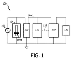
図1は、代表的な実施形態に従ってソリッドステート形照明器具及び位相角検出器を含む調光可能な照明システムを示すブロック図である。図1を参照すると、調光可能照明システム100は、電圧源101から(調光)整流電圧Urectを提供する調光器104及び整流回路105を有している。電圧源101は、種々の具体化例に従って、種々の非整流入力AC線間電圧、例えば100VAC、120VAC、230VAC及び277VACを提供することができる。調光器104は、例えばスライダ104aの垂直動作に応答して電圧源101から電圧信号波形の立上り区間を裁断し(立上り区間調光器)又は立下り区間を裁断する(立下り区間調光器)ことによって調光能力を提供する位相裁断調光器である。一般に、調光電圧Urectの大きさは、調光器104によって設定された調光レベルに比例しており、したがって、位相角又は調光レベルが低いと、その結果として、調光電圧Urectが低くなる。図示の例では、スライダを下方に動かして位相角を減少させ、それによりソリッドステート形照明負荷130により出力させる光の量を減少させ、又、スライダを上方に動かして位相角を増大させ、それによりソリッドステート形照明負荷130により出力される光の量を増大させることが仮定されていると言って良い。
FIG. 1 is a block diagram illustrating a dimmable lighting system including a solid-state luminaire and a phase angle detector in accordance with a representative embodiment. Referring to FIG. 1, a
調光可能照明システム100は、位相角検出器110及び電力変換装置120を更に有している。一般に、位相角検出器110は、整流電圧Urectに基づいて調光器104の位相角を検出し、制御ライン129を介して電力変換装置120に電力制御信号を出力する。電力制御信号は、例えばパルスコード変調(PCM)信号又は他のディジタル信号であるのが良く、検出位相角に基づいて位相角検出器110により定められるデューティサイクルに従って高レベルと低レベルとの間で交番変化することができる。デューティサイクルは、約100パーセント(例えば、高レベルでは連続)から約ゼロパーセント(例えば、低レベルでは連続)までの範囲にあるのが良く、以下において説明するように電力変換装置120の電力設定値を適切に調節してソリッドステート形照明負荷130により放出される光のレベルを制御するために、これら百分率の間の任意の百分率を有する。例えば、70パーセントの百分率デューティサイクルは、電力制御信号の方形波が波周期の70パーセントについて高レベルの状態にあり、波周期の30パーセントについては低レベルの状態にあることを示している。
The
種々の実施形態では、電力変換装置120は、整流回路105から整流電圧Urectを受け取り、そしてソリッドステート形照明負荷130に電力供給するために対応のDC電圧を出力する。電力変換装置120は、2つの変数、即ち、(1)整流回路105を介して例えばスライダ104aの動作により設定される調光器104からの電圧出力の大きさ及び(2)制御ライン129を介して以下に説明する所定の制御機能又はアルゴリズムに従って設定される位相角検出器110によって生じると共に出力される電力制御信号の電力設定値のうちの少なくとも一方に基づいて整流電圧UrectとDC電圧との間で変換する。かくして、電力変換装置120により出力されたDC電圧は、従来型調光照明システムがソリッドステート形照明負荷130により出力される光のそれ以上の減少をもはやもたらさない上限としての低い調光レベルであっても、調光器104により適用される調光器位相角(例えば、調光レベル)を反映する。整流電圧UrectとDC電圧との間で変換する機能は又、当業者には明らかなように、追加の要因、例えば電力変換装置120の特性、ソリッドステート形照明負荷130の形式及び形態、種々の具体化例の他の用途及び設計上の要件で左右される場合がある。
In various embodiments, the
種々の実施形態では、調光可能照明システム100は、ソリッドステート形照明負荷130の選択的閉ループ電力抑制を可能にする。換言すると、電力変換装置120は、位相角検出器110により検出される調光器位相角に応じて、閉ループモード又は開ループモードで選択的に動作する。開ループモードでは、位相角検出器110は、電力制御信号を一定又は固定電力設定値に設定し、この一定又は固定電力設定値は、電力変換装置120の動作点を固定する。したがって、電力変換装置120は、受け取った電圧Urectの大きさにのみに基づいて整流電圧UrectとDC電圧との間の変換を行い、電圧源101からの指定された大きさの電力をソリッドステート形照明負荷130に送る。閉ループモードでは、位相角検出器110は、電力制御信号の可変電力設定値を計算し、かかる可変電力設定値は、電力変換装置120の動作点を動的に調節する。したがって、電力変換装置120は、電力制御信号の電力設定並びに受け取った電圧Urectの大きさに基づいて整流電圧UrectとDC電圧との間で変換を行う。
In various embodiments,
調光可能照明システム100は、電力変換装置120の高開ループ範囲と低開ループ範囲との間で閉ループ範囲を提供するよう構成されているのが良い。図3を参照して以下に詳細に説明するように、位相角検出器110は、電力制御信号を検出位相角が所定の第1のしきい値よりも大きい場合、高い固定電力設定値に設定し、検出位相角が所定の第2のしきい値よりも小さい場合、低い固定電力設定値に設定し、検出位相角が第1のしきい値と第2のしきい値との間にある場合、計算された可変電力設定値に設定することができる。例えば、位相角検出器110が第1のしきい値(例えば、第1の低い調光レベル)よりも大きい位相角を検出した場合、位相角検出器は、電力制御信号を高デューティサイクル(例えば、100パーセント)に設定し、電力変換装置120は、その出力電力を整流電圧Urectの大きさの変化にのみ基づかせる。同様に、位相角検出器110が第2のしきい値(例えば、第2の低い調光レベル又はゼロ光出力)よりも小さい位相角を検出した場合、位相角検出器は、電力制御信号を低デューティサイクル(例えば、ゼロパーセント)に設定し、電力変換装置120は、その出力電力を整流電圧Urectの大きさの変化にのみ基づかせる。調光器位相角検出110が第1のしきい値よりも小さく且つ第2のしきい値よりも大きい位相角を検出した場合、調光器位相角検出器110は、電力制御信号のデューティサイクルを動的に計算して検出位相角を反映させ、電力変換装置120は、その出力電力を計算されたデューティサイクル及び整流電圧Urectの大きさの変化に基づかせる。したがって、ソリッドステート形照明負荷130により出力される光は、例えば第1のしきい値未満のような、従来型システムでは光出力に影響を及ぼさなかったであろう低い調光レベルであっても、調光を続ける。
The
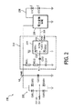
図2は、代表的な実施形態に従ってソリッドステート形照明器具及び調光器位相角検出回路を含む調光制御システムを示す回路図である。図2の全体的コンポーネントは、図1のコンポーネントとほぼ同じであるが、例示の形態に従って種々の代表的なコンポーネントに対する細部が提供されている。当然のことながら、本発明の教示の範囲から逸脱することなく他の形態を具体化できる。 FIG. 2 is a circuit diagram illustrating a dimming control system including a solid-state lighting fixture and a dimmer phase angle detection circuit in accordance with a representative embodiment. The overall components of FIG. 2 are substantially the same as the components of FIG. 1, but details are provided for various representative components in accordance with the illustrated embodiment. Of course, other embodiments may be implemented without departing from the scope of the teachings of the present invention.
図2を参照すると、調光制御システム200は、整流回路205、調光器位相角検出回路210(破線のボックスで示されている)、電力変換装置220及びLED負荷230を有している。整流回路105に関連して上述したように、整流回路205は、電圧源(図示せず)から(低減された)整流されていない電圧を受け取るようDim hot及びDim neutral入力によって示された調光器(図示せず)に接続されている。図示の形態では、整流回路205は、整流電圧ノードN2とアース電圧との間に接続された4つのダイオードD201〜D204を有する。整流電圧ノードN2は、(低減)整流電圧Urectを受け取り、この整流電圧ノードは、整流回路205と並列に接続された入力フィルタリングキャパシタC215を介してアースに接続されている。
Referring to FIG. 2, the dimming
位相角検出器210は、整流電圧Urectに基づいて調光器位相角(調光レベル)を検出し、PWM出力219からの電力制御信号を制御ライン229により電力変換装置220に出力し、それによりLED負荷230の動作を制御する。これにより、位相角検出210は、検出位相角に基づいて入力電圧源からLED負荷230に送られる電力の大きさを選択的に調節することができる。図示の代表的な実施形態では、電力制御信号は、電力変換装置220に提供されるべき電力設定値に一致して位相角検出210により定められたデューティサイクルを有するPWM信号である。また、図示の代表的な実施形態では、位相角検出回路210は、マイクロコントローラ215を有し、マイクロコントローラ215は、以下に詳細に説明するように、整流電力Urectの波形を用いて調光器位相角を求め、そしてPWM電力制御信号をPWM出力219から出力する。
The
電力変換装置220は、整流電圧ノードN2のところで整流電圧Urectを受け取り、LED負荷230に電力供給するために整流電圧Urectを対応のDC電圧に変換する。電力変換装置220は、位相検出器回路210により提供されたPWM電力制御信号に応じて、例えばリス(Lys)に付与された米国特許第7,256,554号明細書(この米国特許を参照により引用し、その記載内容を本明細書の一部とする)に記載されているように開ループ(又はフィードフォワード)方式及び閉ループ方式で選択的に動作する。種々の実施形態では、電力変換装置220は、例えばエステー・マイクロエレクトロニクス(ST Microelectronics)社から入手できるL6562であるのが良いが、本発明の教示の範囲から逸脱することなく、他形式の電力変換装置又は他の電子回路用変成器及び/又はプロセッサを使用することができる。例えば、電力変換装置220は、固定オフタイム且つ力率補正型のシングルステージ反転バック変換装置であるのが良いが、基準開ループ制御方式の電力変換装置であればどのような形式のものであっても利用することができる。
The
LED負荷230は、電力変換装置220の出力とアースとの間で代表的なLED231,232で示されている直列に接続された一連のLEDを有する。LED負荷230を通る負荷電流の大きさ及びかくしてLED負荷230により放出される光の量は、直接、電力変換装置220により出力される電力の大きさによって制御される。電力変換装置220により出力される電力の大きさは、整流電圧Urectの大きさ及び位相角検出回路210により検出された調光器の検出位相角(調光レベル)によって制御される。
The
図3は、代表的な実施形態に従って電力制御信号と調光器位相角の関係を示すグラフ図である。図3を参照すると、縦軸は、低い又は最小の電力設定値から上方に増大する電力制御信号の電力設定値を示し、横軸は、低い又は最初の調光レベルを起点として右側から左側に増大する調光器位相角(例えば、位相角検出回路210により検出される)を示している。 FIG. 3 is a graph illustrating the relationship between the power control signal and the dimmer phase angle according to a representative embodiment. Referring to FIG. 3, the vertical axis indicates the power setting value of the power control signal that increases upward from the low or minimum power setting value, and the horizontal axis indicates the low or initial dimming level as a starting point from the right side to the left side. It shows the dimmer phase angle increasing (eg, detected by the phase angle detection circuit 210).
位相角検出回路210により調光器位相角が第1の位相角θ1で示された所定の第1のしきい値よりも大きいことが判定されると、PWM電力制御信号のデューティサイクルは、電力変換装置220の動作点を固定するその最も高い電力設定値(例えば、100パーセントデューティサイクル)に設定される。したがって、電力変換装置220は、整流電圧Urectの大きさにのみ基づいて電力を決定し、これをLED負荷230に出力する。換言すると、電力変換装置220は、位相裁断調光器だけが整流回路205を介して電力変換装置220の出力に送られる電力を調整するよう開ループで動作する。種々の実施形態では、第1の位相角θ1は、もし上述のように構成されていなければ、調光器での調光レベルのそれ以上の減少もLED負荷230により出力される光を減少させることがなかったであろう、例えば最大設定光出力の約15〜30パーセントの調光器位相角であるのが良い。
When the phase
位相角検出回路210により調光器位相角が第1の位相角θ1よりも小さいことが判定されると、位相角検出回路は、PWM電力制御信号の百分率デューティサイクルを最も高い電力設定値から下方に調節し始め、その目的は、電力変換装置220の出力電力を減少させることにある。したがって、電力変換装置220は、整流電圧Urectの大きさ及び例えばマイクロコントローラ215によって調整されるPWM電力制御信号の電力設定値に基づいて電力を決定し、これをLED負荷230に出力する。換言すると、電力変換装置220は、PWM電力制御信号からのフィードバックを用いて閉ループで動作する。
When the phase
PWM電力制御信号は、検出調光器位相角が以下に説明する第2の位相角θ2により表される所定の第2のしきい値に達するまで検出調光器位相角の減少に応答して下方に調節される。図3の代表的な曲線は、第1の位相角θ1のところでの最も高い電力設定値から第2の位相角θ2のところの最も低い電力設定値までの直線傾斜(ランプ)により表される記号線形パルス幅変調を示している。しかしながら、非直線傾斜を本発明の教示の範囲から逸脱しないで組み込むことができる。例えば、種々の実施形態では、PWM電力制御信号の非線形関数が当業者には明らかであるように調光器のスライダの動作に対応したLED負荷230によって出力される光の線形感を作るのに必要な場合がある。
The PWM power control signal is responsive to a decrease in the detected dimmer phase angle until the detected dimmer phase angle reaches a predetermined second threshold represented by a second phase angle θ 2 described below. Adjusted downward. The representative curve of FIG. 3 is represented by a linear slope (ramp) from the highest power setting at the first phase angle θ 1 to the lowest power setting at the second phase angle θ 2. Symbolic pulse width modulation is shown. However, non-linear slopes can be incorporated without departing from the scope of the teachings of the present invention. For example, in various embodiments, a non-linear function of the PWM power control signal is used to create a linear sense of the light output by the
位相角検出回路210により調光器位相角が第2の位相角θ2で表される指定の第2のしきい値よりも小さいレベルまで減少したことが判定されると、PWM電力制御信号のデューティサイクルは、電力変換装置220の動作点を固定するその最も低い電力設定値(例えば、ゼロパーセントデューティサイクル)に設定される。したがって、電力変換装置220は、整流電圧Urectの大きさにのみ基づいて電力を決定し、これをLED負荷230に出力する。換言すると、電力変換装置220は、位相裁断調光器だけが整流回路205を介して電力変換装置220の出力に送られる電力を調整するよう再び開ループで動作する。
When it is determined by the phase
第2の位相角θ2の値は、当業者には明らかなように、任意特定の状況について固有の利点を提供し又は種々の具体化例の特定用途向けの設計上の要件を満たすよう様々であって良い。例えば、第2の位相角θ2の値は、LED負荷230への電力のそれ以上の減少が負荷を電力変換装置220の最小負荷要件を下回らせるような調光器位相角であるのが良い。変形例として、第2の位相角θ2の値は、LED負荷230により出力される光の所定の最小レベルに対応した調光器位相角であっても良い。種々の変形実施形態では、第2の位相角θ2は、単にゼロであっても良く、この場合、電力変換装置220は、PWM電力制御信号からのフィードバックを用いて閉ループモードで動作し、ついには、調光器位相角は、その最小レベルまで減少する(これは、ゼロ又はゼロよりも幾分大きな最小レベルであって良い)。
The value of the second phase angle θ 2 may vary to provide unique advantages for any particular situation or to meet the design requirements for the specific application of various embodiments, as will be apparent to those skilled in the art. It may be. For example, the value of the second phase angle θ 2 may be a dimmer phase angle such that further reduction of power to the
図4は、代表的な実施形態に従って電力変換装置の出力電力を制御するための電力制御信号を設定する方法を示す流れ図であり、図4に示されている方法は、例えば、図2に示されたマイクロコントローラ215によって実施されるのが良いが、本発明の教示の範囲から逸脱することなく他形式のプロセッサ及びコントローラを用いることができる。 FIG. 4 is a flow diagram illustrating a method for setting a power control signal for controlling the output power of a power converter according to a representative embodiment. The method illustrated in FIG. 4 is illustrated, for example, in FIG. However, other types of processors and controllers may be used without departing from the scope of the present teachings.
ブロックS421では、調光器位相角θを位相角検出回路210によって求める。ブロックS422では、検出調光器位相角が所定の第1のしきい値に対応した第1の位相角θ1以上であるかどうかを判定する。検出調光器位相角が第1の位相角θ1以上の場合(ブロックS422:Yes)、ブロックS423においてPWM電力制御信号を固定された最も高い設定値(例えば、100パーセントデューティサイクル)に設定する。ブロックS430において、PWM電力制御信号を制御ライン229により電力変換装置220に送り、この方法は、ブロックS421に戻って調光器位相角θの検出を続行する。
In block S421, the dimmer phase angle θ is obtained by the phase
検出調光器位相角が第1の位相角θ1よりも小さい場合(ブロックS422:No)、ブロックS424では、検出調光器位相角が第2のしきい値に対応した第2の位相角θ2以下であるかどうかを判定する。検出調光器位相角が第2の位相角θ2以下の場合(ブロックS424:Yes)、ブロックS425においてPWM電力制御信号を固定された最も低い設定値(例えば、ゼロパーセントデューティサイクル)に設定する。ブロックS430において、PWM電力制御信号を制御ライン229により電力変換装置220に送り、この方法は、ブロックS421に戻って調光器位相角θの検出を続行する。
When the detected dimmer phase angle is smaller than the first phase angle θ 1 (block S422: No), in block S424, the detected dimmer phase angle corresponds to the second threshold value. It is determined whether θ 2 or less. If the detected dimmer phase angle is less than or equal to the second phase angle θ 2 (block S424: Yes), the PWM power control signal is set to a fixed lowest setting value (eg, zero percent duty cycle) in block S425. . In block S430, a PWM power control signal is sent to the
検出調光器位相角が第2の位相角θ2よりも大きい場合(ブロックS424:No)、PWM電力制御信号をブロックS426で計算する。例えば、PWM電力制御信号の百分率デューティサイクルを例えば対応の電力設定値を提供するためにマイクロコントローラ215によって実行されるソフトウェア及び/又はファームウェアアルゴリズムとして具体化される検出調光器位相角の所定の関数に従って計算するのが良い。所定の関数は、調光レベルの減少に対応した百分率デューティサイクルの線形減少をもたらす線形関数であるのが良い。変形例として、所定の関数は、調光レベルの減少に対応した百分率デューティサイクルの非線形減少をもたらす非線形関数であっても良い。S427において、PWM電力制御信号のデューティサイクルを計算された百分率に設定し、そしてブロックS430において制御ライン229を介してこれを電力変換装置220に送る。この方法は、ブロックS421に戻り、調光器位相角θの検出を続行する。
If the detected dimmer phase angle is greater than the second phase angle θ 2 (block S424: No), the PWM power control signal is calculated in block S426. For example, a predetermined function of the detected dimmer phase angle embodied as a software and / or firmware algorithm executed by the
図示の実施形態では、所定の関数に従って、ブロックS422において検出調光器位相角を第1の位相角θ1よりも低いレベルに低下したものと判定された後であってブロックS426においてPWM電力制御信号を計算する前に、検出調光器位相角が第2の位相角θ2以下であるかにどうかに関する判定をブロックS424において行う。しかしながら、種々の変形実施形態では、第2の位相角θ2との明確な比較を除外しても良く、その結果、検出調光器位相角θが第1の位相角θ1よりも小さいことが一端判定されると、電力制御信号をブロックS426で計算する(電力変換装置は、閉ループモードで動作している)。例えば、所定の関数それ自体の結果として、百分率デューティサイクルは、第2の位相角θ2で固定された最も低い電力設定値に設定され、この場合、検出調光器位相角θと第2の位相角θ2の別個の比較を行う必要はない。 In the illustrated embodiment, PWM power control is performed in block S426 after determining that the detected dimmer phase angle has been reduced to a level lower than the first phase angle θ 1 in block S422 according to a predetermined function. before computing the signal, the detection dimmer phase angle performed at block S424 the judgment as to whether the whether the second phase angle theta 2 below. However, in various alternative embodiments, a clear comparison with the second phase angle θ 2 may be omitted, so that the detected dimmer phase angle θ is smaller than the first phase angle θ 1. Is once determined, the power control signal is calculated in block S426 (the power converter is operating in the closed loop mode). For example, as a result of the predetermined function itself, the percentage duty cycle is set to the lowest power setting fixed at the second phase angle θ 2 , where the detected dimmer phase angle θ and the second There is no need to make a separate comparison of the phase angle θ 2 .
図5は、代表的な実施形態に従って電力変換装置の出力電圧を決定する方法を示す流れ図である。図4に示されている方法は、例えば、図2に示された電力変換装置220によって実施できるが、本発明の教示の範囲から逸脱することなく他形式のプロセッサ及びコントローラを用いることができる。
FIG. 5 is a flow diagram illustrating a method for determining an output voltage of a power converter according to a representative embodiment. The method shown in FIG. 4 can be implemented, for example, by the
ブロックS521において、電力変換装置220は、整流回路205から(低減された)整流された電圧Urectを受け取る。同時に、ブロックS522において、電力装置220は、図4のブロックS430に示されているように、位相角検出器210からPWM電力制御信号を受け取る。ブロックS523において、PWM電力制御信号が固定された最も高い設定値にあるかどうかを判定する。PWM電力制御信号が固定された最も高い設定値にあれば(ブロックS523:Yes)、電力変換装置220の動作点を固定し、ブロックS524において、ブロックS521で受け取った整流電圧の大きさにのみ基づいて出力電圧を開ループモードで決定する。決定した出力電力をブロックS530においてLED負荷230に出力し、この方法は、ブロックS521に戻る。
In block S521, the
PWM電力制御信号が固定された最も高い設定値にない場合(ブロックS523:No)、PWM電力制御信号が固定された最も低い設定値にあるかどうかをブロックS525で判定する。PWM電力制御信号が固定された最も低い設定値にある場合(ブロックS525:Yes)、電力変換装置220の動作点を固定し、ブロックS524において、ブロックS521で受け取った整流電圧の大きさにのみ基づいて出力電力を開ループモードで決定する。決定した出力電力をブロックS530においてLED負荷230に出力し、この方法は、ブロックS521に戻る。
If the PWM power control signal is not at the fixed highest setting value (block S523: No), it is determined at block S525 whether the PWM power control signal is at the lowest fixed setting value. When the PWM power control signal is at the lowest fixed setting value (block S525: Yes), the operating point of the
PWM電力制御信号が固定された最も低い設定値にない場合(ブロックS525:No)、ブロックS526において、ブロックS521で受け取った整流電圧の大きさ及びブロックS522で受け取ったPWM電力制御信号に基づいて出力電力を閉ループモードで決定する。ブロックS530において、決定した出力電力をLED負荷230に出力し、この方法は、ブロックS521に戻る。
If the PWM power control signal is not at the lowest fixed setting value (block S525: No), output is made in block S526 based on the magnitude of the rectified voltage received in block S521 and the PWM power control signal received in block S522. Determine power in closed loop mode. In block S530, the determined output power is output to the
図示の実施形態では、ブロックS525において、ブロックS523においてPWM電力制御信号が固定された最も高い電力設定値にないことが判定された後であってブロックS526において出力電力を整流電圧の大きさとPWM電力制御信号の両方に基づいて決定する前に、PWM電力制御信号が固定された最も低い電力設定値にあるかどうかに関する別個の判定を行う。しかしながら、種々の変形実施形態では、固定された最も低い電力設定値との明確な比較を除外しても良く、その結果、固定された最も高い電力設定値よりも小さい任意の電力設定値(PWM電力制御信号により提供される)において整流電圧の大きさとPWM電力制御信号の両方に基づいて出力電力信号を制御する。例えば、電力変換装置220は、電力設定値の減少に対応して減少するレベルの出力電力を出力するよう構成されるのが良く、その結果、出力電力の最も低いレベルは、最も低い電力設定値に一致するようになり、この場合、PWM電力制御信号の電力設定値と所定の固定された最も低い電力設定値の別個の比較を行う必要はない。
In the illustrated embodiment, after it is determined in block S525 that the PWM power control signal is not at the highest fixed power setting value in block S523, the output power is converted into the magnitude of the rectified voltage and the PWM power in block S526. Before making a decision based on both control signals, a separate determination is made as to whether the PWM power control signal is at a fixed lowest power setting. However, in various alternative embodiments, a clear comparison with the fixed lowest power setting value may be eliminated, so that any power setting value (PWM) that is smaller than the fixed highest power setting value may be excluded. The output power signal is controlled based on both the magnitude of the rectified voltage and the PWM power control signal (provided by the power control signal). For example,
再び図2を参照すると、図示の代表的な実施形態では、位相角検出回路210は、マイクロコントローラ215を有し、このマイクロコントローラは、整流電圧入力波形を用いて調光器位相角を求める。マイクロコントローラ215は、頂部ダイオードD211と底部ダイオードD212との間に接続されたディジタル入力ピン218を有する。頂部ダイオードD211は、ディジタル入力ピン218に接続されたアノード及び電圧源Vccに接続されたカソードを有し、底部ダイオード112には、アースに接続されたアノード及びディジタル入力ピン218に接続されたカソードを有する。マイクロコントローラ215は、ディジタル出力、例えばPWM出力219を更に有する。
Referring again to FIG. 2, in the illustrated exemplary embodiment, the phase
種々の実施形態では、マイクロコントローラ215は、例えばマイクロチップ・テクノロジー・インコーポレイテッド(Microchip Technology, Inc.)から入手できるPIC12F683であるのが良いが、本発明の教示から逸脱することなく、他形式のマイクロコントローラ又は他のプロセッサを使用することができる。例えば、マイクロコントローラ215の機能は、種々の機能を実行するためにソフトウェア又はファームウェアを用いてプログラムできる1つ又は2つ以上のプロセッサ及び/又はコントローラ並びに対応のメモリによって具体化でき又は幾つかの機能を実行する専用ハードウェアと他の機能を実行するプロセッサ(例えば、1つ又は2つ以上のプログラムマイクロプロセッサ及び関連回路)の組み合わせとして具体化できる。種々の実施形態において採用できるコントローラコンポーネントの例としては、上述したように従来型マイクロプロセッサ、マイクロコントローラ、ASIC及びFPGAが挙げられるが、これらには限定されない。
In various embodiments, the
位相角検出回路210は、種々の受動的電子部品、例えば第1及び第2のキャパシタC213,C214並びに第1及び第2の抵抗器R211,R212を更に有する。第1のキャパシタC213は、マイクロコントローラ215のディジタル入力ピン218と検出ノードへの位置との間に接続されている。第2のキャパシタC214は、検出ノードN1とアースとの間に接続されている。第1及び第2の抵抗器R211,R212は、整流電圧ノードN2と検出ノードN1との間に直列に接続されている。図示の実施形態では、例えば、第1のキャパシタC213は、約560pFの値を有するのが良く、第2のキャパシタC214は、約10pFの値を有するのが良い。また、例えば、第1の抵抗器R211は、約1メガオームの値を有するのが良く、第2の抵抗器R212は、約1メガオームの値を有するのが良い。しかしながら、第1及び第2のキャパシタC213,C214並びに第1及び第2の抵抗器R211,R212のそれぞれの値は、当業者には明らかなように、任意特定の状況について固有の利点を提供し又は種々の具体化例の特定用途向けの設計上の要件を満たすよう様々であって良い。
The phase
整流された(低減されて整流された)減圧Urectは、マイクロコントローラ215のディジタル入力ピン218に結合されたACである。第1の抵抗器R211及び第2の抵抗器R212は、ディジタル入力ピン218に流れる電流を制限する。整流電圧Urectの信号波形が高になると、第1のキャパシタC213は、第1及び第2の抵抗器R211,R212を介して立上り区間が充電される。マイクロコントローラ215内の頂部ダイオードD211は、例えば、ディジタル入力ピン218をVccよりも高い1つのダイオードドロップにクランプする。第1のキャパシタC213は、整流電圧Urectの信号波形の立下り区間において放電し、ディジタル入力ピン218は、底部ダイオードD212によりアース電圧よりも低い1つのダイオードドロップにクランプされる。したがって、マイクロコントローラ215のディジタル入力ピン218のところの結果として生じる論理レベルディジタルパルスは、裁断された整流電圧Urectの運動に厳密に追随し、かかる実施例が図6A〜図6Cに示されている。
The rectified (reduced and rectified) decompression Urect is an AC coupled to the
特に、図6A〜図6Cは、代表的な実施形態に従ってディジタル入力ピン218のところのサンプル波形及び対応のディジタルパルスを示している。各図の中の上側の波形は、裁断された整流電圧Urectを示し、この場合、裁断の量は、調光のレベルを反映している。例えば、波形は、調光器の出力のところに現れる全170V(又は欧州に関しては340V)ピークの整流正弦波の一部分を示していると言える。下側の方形波の波形は、マイクロコントローラ215のディジタル入力ピン218のところに見える対応のディジタルパルスを示している。特に、各ディジタルパルスの長さは、裁断波形に対応しており、かくして、調光器の内部スイッチが「オン」である時間の長さに等しい。ディジタル入力ピン218を介してディジタルパルスを受け取ることにより、マイクロコントローラ215は、調光器を設定したレベルを求めることができる。
In particular, FIGS. 6A-6C illustrate sample waveforms and corresponding digital pulses at
図6Aは、調光器が波形の隣りに示されている調光器スライダの頂部位置により示されたその最も高い設定値にあるときの整流電圧Urect及び対応のディジタルパルスのサンプル波形を示している。図6Bは、調光器が波形の隣りに示されている調光器スライダの中間位置により示された中間設定値にあるときの整流電圧Urect及び対応のディジタルパルスのサンプル波形を示している。図6Cは、調光器が波形の隣りに示されている調光器スライダの底部位置により示されたその最も低い設定値にあるときの整流電圧Urect及び対応のディジタルパルスのサンプル波形を示している。 FIG. 6A shows a sample waveform of the rectified voltage Urect and the corresponding digital pulse when the dimmer is at its highest setting indicated by the top position of the dimmer slider shown next to the waveform. Yes. FIG. 6B shows the sample waveform of the rectified voltage Urect and the corresponding digital pulse when the dimmer is at the intermediate set point indicated by the intermediate position of the dimmer slider shown next to the waveform. FIG. 6C shows the sample waveform of the rectified voltage Urect and the corresponding digital pulse when the dimmer is at its lowest setting indicated by the bottom position of the dimmer slider shown next to the waveform. Yes.
図7は、代表的な実施形態に従って調光器の調光器位相角を検出する方法を示す流れ図である。この方法は、例えば図2に示されているマイクロコントローラ215によって実行されるファームウェア及び/又はソフトウェアによって又はより一般的には図1に示されている位相角検出器110によって実施できる。
FIG. 7 is a flow diagram illustrating a method for detecting a dimmer phase angle of a dimmer according to a representative embodiment. This method can be implemented, for example, by firmware and / or software executed by the
図7のブロックS721において、入力信号のディジタルパルスの立上り区間(例えば、図6A〜図6Cの下側の波形の立上り区間によって示される)を検出し、ブロックS722において、例えばマイクロコントローラ215のディジタル入力ピン218のところでのサンプリングが始まる。図示の実施形態では、信号をちょうど電源半サイクルに満たない程度に等しい所定の時間の間、ディジタルサンプリングする。信号をサンプリングするたびに、ブロックS723において、サンプルが高レベル(例えば、数値“1”)を有するか低レベル(例えば、数値“0”)を有するかを判定する。図示の実施形態では、ブロックS723において、サンプルが数値“1”であるかどうかを判定する比較を行う。サンプルが数値“1”である場合(ブロックS723:Yes)、ブロックS724においてカウンタを増分し、サンプルが数値“1”ではない場合(ブロックS723:No)、ブロックS725において僅かな遅延を挿入する。サンプルが数値“1”であると判定されるか数値“0”で判定されるかどうかとは無関係に遅延を挿入して(例えば、マイクロコントローラ215の)クロックサイクル数が等しくなるようにする。
In block S721 of FIG. 7, the rising edge of the digital pulse of the input signal (eg, indicated by the rising edge of the lower waveform of FIGS. 6A to 6C) is detected, and in block S722, for example, the digital input of the
ブロックS726において、電源半サイクル全体をサンプリングしたかどうかを判定する。電源半サイクルが完了していない場合(ブロックS726:No)、この方法は、ブロックS722に戻って再びディジタルピン218のところの信号をサンプリングする。電源半サイクルが完了している場合(ブロックS726:Yes)、サンプリングが止まり、カウンタ値(ブロックS724で累積されている)をブロックS727において現在の調光器位相角又は調光レベルであると呼び、このカウンタ値は、例えばメモリに記憶され、かかるその実施例については上述した。カウンタをゼロにリセットし、マイクロコントローラ215は、次の立上り区間がサンプリングを再び開始するまで待つ。
In block S726, it is determined whether the entire power supply half cycle has been sampled. If the power supply half cycle is not complete (block S726: No), the method returns to block S722 and samples the signal at the
例えば、マイクロコントローラ215が電源半サイクル中に255個のサンプルを採取したものと仮定する。調光レベルがスライダによってその範囲の頂部のところで設定された場合(例えば、図6Aに示されている)カウンタは、図6のブロックS724において約255に増分することになる。調光レベルがスライダによってその範囲の底部のところで設定された場合(例えば、図6Cに示されているように)、カウンタは、ブロックS724において約10又は20に増分するに過ぎない。調光レベルがスライダの範囲の中間のどこかの場所で設定された場合(例えば、図6Bに示されているように)、カウンタは、ブロックS724において約128まで増分する。かくして、カウンタの値は、マイクロコントローラ215に調光器が設定されたレベル又は調光器の位相角の正確な表示を与える。種々の実施形態では、調光器位相角は、例えば、カウンタ値の所定の関数を用いてマイクロコントローラ215によって計算でき、この場合、関数は、当業者には明らかなように、任意特定の状況について固有の利点を提供し又は種々の具体化例の特定用途向けの設計上の要件を満たすよう様々であって良い。
For example, assume that
したがって、最小限の受動的コンポーネント及びマイクロコントローラ(又は他のプロセッサ若しくは処理回路)のディジタル入力構造を用いて調光器の位相角を電子的に検出するこができる。一実施形態では、位相角検出は、AC結合回路、マイクロコントローラダイオードクランプディジタル入力構造及び調光器設定レベルを決定するよう実行されるアルゴリズム(例えば、ファームウェア、ソフトウェア及び/又はハードウェアによって具体化される)を用いて達成される。加うるに、最小限のコンポーネント数で且つマイクロコントローラディジタル入力構造を利用して調光器の状態を測定することができる。 Thus, the dimmer phase angle can be electronically detected using a minimum of passive components and a digital input structure of a microcontroller (or other processor or processing circuit). In one embodiment, phase angle detection is implemented by an algorithm (e.g., firmware, software and / or hardware) that is executed to determine the AC coupling circuit, microcontroller diode clamp digital input structure and dimmer setting level. To achieve this. In addition, the dimmer state can be measured with a minimum number of components and utilizing a microcontroller digital input structure.
加うるに、調光器位相角検出回路及び電力コントローラ並びに関連のアルゴリズムを含む調光制御システムを、位相裁断調光器の小さい調光器位相角での調光を制御することが望ましい種々の状況で使用でき、かかる調光は、もしそのように構成されていなければ、従来型システムでは停止するようなものである。調光制御システムは、調光範囲を増大させ、かかる調光制御システムを特に低い低端調光レベルが例えば最大光出力の約5パーセント未満の範囲内に存在することが必要な状況では、位相裁断調光器に接続されたLED負荷を備えた電子回路用変成器に使用できる。 In addition, a dimming control system, including a dimmer phase angle detection circuit and a power controller and related algorithms, can be used to control dimming at a small dimmer phase angle of the phase cut dimmer. It can be used in situations, and such dimming is like stopping in conventional systems if not so configured. The dimming control system increases the dimming range, and in situations where such a dimming control system requires a particularly low low end dimming level to be present, for example, in a range of less than about 5 percent of the maximum light output, It can be used in an electronic circuit transformer with an LED load connected to a dimmer.
種々の白色光照明装置において種々の実施形態としての調光制御システムを具体化することができる。さらに、調光制御システムは、種々の製品をより調光器フレンドリーとするために種々の製品の「スマート」改良例のビルディングブロックとして使用することができる。 The dimming control system as various embodiments can be embodied in various white light illumination devices. Furthermore, the dimming control system can be used as a “smart” improvement building block for various products to make the various products more dimmer friendly.
種々の実施形態において、調光器位相角検出器110、位相角検出回路210又はマイクロプロセッサ215の機能をハードウェア、ファームウェア又はソフトウェアアーキテクチャの任意の組み合わせで構成された1つ又は2つ以上の処理回路によって実行でき、かかる機能は、種々の機能を実行することができる実行可能なソフトウェア/ファームウェアにより実行可能なコードを記憶するそれ自体のメモリ(例えば、不揮発性メモリ)を含むのが良い。例えば、それぞれの機能をASIC、FPGA等を用いて実行できる。
In various embodiments, the function of the dimmer
当業者であれば容易に理解されるように、本明細書において記載した全てのパラメータ、寸法、材料及び形態は、例示であり、実際のパラメータ、寸法、材料及び/又は形態は、本発明の教示が用いられる1つ又は複数の特定の用途で決まる。当業者であれば、本明細書において記載した特定の本発明の実施形態の多くの均等例を認識し又は日常的に行われる程度に過ぎない実験を用いて確かめることができよう。したがって、上述の実施形態は、例示として提供されており、本発明の実施形態は、特許請求の範囲に記載された本発明の範囲及びその均等範囲内で、具体的に説明すると共にクレーム請求した形態以外の形態で実施できることは理解されるべきである。本発明の実施形態は、本明細書において説明した個々の各々の特徴、システム、物品、材料、キット及び/又は方法に関する。加うるに、2つ又は3つ以上の特徴、システム、物品、材料、キット及び/又は方法の任意の組み合わせは、かかる特徴、システム、物品、材料、キット及び/又は方法が相互に矛盾しない限り、本発明の範囲に含まれる。 As will be readily appreciated by those skilled in the art, all parameters, dimensions, materials and forms described herein are exemplary, and actual parameters, dimensions, materials and / or forms are It depends on the particular application or applications in which the teaching is used. Those skilled in the art will recognize, or be able to ascertain using no more than routine experimentation, many of the equivalents of the specific embodiments of the invention described herein. Accordingly, the foregoing embodiments have been provided by way of example, and embodiments of the present invention have been specifically described and claimed within the scope of the present invention as set forth in the appended claims and equivalents thereof. It should be understood that embodiments other than forms can be implemented. Embodiments of the invention relate to each individual feature, system, article, material, kit, and / or method described herein. In addition, any combination of two or more features, systems, articles, materials, kits and / or methods may be used unless such features, systems, articles, materials, kits and / or methods are consistent with each other. And within the scope of the present invention.
本明細書において定められると共に用いられている全ての定義的記載は、辞書的定義、参照により引用した文献に記載されている定義及び/又は指定用語の通常の意味に優先して用いられているものと理解されるべきである。 All definitive statements defined and used herein are used in preference to the lexical definition, the definitions given in the documents cited by reference and / or the ordinary meaning of the specified terms. Should be understood.
原文明細書及び原文特許請求の範囲において用いられている不定冠詞“a”及び“an”は、明示の別段の指定がなければ、“at least one(少なくとも1つ)”を意味するものと理解されるべきである。本明細書及び特許請求の範囲に用いられている1つ又は2つ以上の要素のリストに言及して「少なくとも1つ」という語句は、要素のリスト中の要素のうちの任意の1つ又は2つ以上から選択された少なくとも1つの要素を意味するものと理解されるべきであるが、必ずしも要素のリスト内に具体的に記載された各要素又は全ての要素のうちの少なくとも1つを含むというわけではなく且つ要素のリスト中の要素の任意の組み合わせを排除するものではない。この定義は又、具体的に記載した要素に関連しているにせよ関連していないにせよいずれにせよ、要素がオプションとして「少なくとも1つ」という語句が適用される要素のリスト内に具体的に記載された要素以外に存在する場合がある。かくして、非限定的な例として、「A及びBのうちの少なくとも一方」又は同様な言い方として「A又はBのうちの少なくとも一方」又は同様な言い方として「A及び/又はBのうちの少なくとも一方」は、一実施形態では、少なくとも1つ、オプションとして、2つ以上のAを含み、Bが存在していない(オプションとして、B以外の要素を含む)ことを意味し、別の実施形態では、少なくとも1つ、オプションとして、2つ以上のBを含み、Aが存在していない(オプションとして、A以外の要素を含む)ことを意味し、更に別の実施形態では、少なくとも1つ、オプションとして2つ以上のA及び少なくとも1つ、オプションとして2つ以上のBを含む(更にオプションとして、他の要素を含む)こと等を意味する場合がある。 The indefinite articles "a" and "an" used in the original specification and claims are understood to mean "at least one" unless expressly specified otherwise. It should be. In reference to a list of one or more elements used in the specification and claims, the phrase “at least one” refers to any one of the elements in the list of elements, or It should be understood as meaning at least one element selected from two or more, but necessarily includes at least one of each element or all elements specifically listed in the list of elements Neither does it exclude any combination of elements in the list of elements. This definition is also specific within the list of elements to which the word “at least one” applies as an option, whether or not related to the specifically stated element. It may exist in addition to the elements described in. Thus, as a non-limiting example, “at least one of A and B” or similar term “at least one of A or B” or similar term “at least one of A and / or B” "In one embodiment includes at least one, optionally two or more A's, and B does not exist (optionally includes elements other than B), in another embodiment , At least one, optionally including two or more B, meaning that A does not exist (optionally includes elements other than A), and in yet another embodiment, at least one optional May include two or more A and at least one, and optionally two or more B (and optionally include other elements).
また、理解されるべきこととして、明示の別段の指定がなければ、2つ以上のステップ又は行為を含む特許請求の範囲に記載された任意の方法において、この方法のステップ又は行為の順序は、必ずしも、方法のステップ又は行為を記載している順序には限定されない。さらに、単なる説明の便宜上、特許請求の範囲の記載に参照符号(もしあれば)設けられ、かかる参照符号は、本発明を何ら限定するものと解されてはならない。 It should also be understood that in any method recited in a claim that includes two or more steps or actions unless explicitly stated otherwise, the order of the steps or actions of this method is: It is not necessarily limited to the order in which the method steps or acts are described. Furthermore, for convenience of explanation, reference signs (if any) are provided in the claims, and such reference signs should not be construed as limiting the present invention in any way.
原文特許請求の範囲並びに原文明細書において、全ての移行語句、例えば“comprising”(翻訳文では、「〜を有する」としている場合が多い)、“including”(翻訳文では、「〜を含む」としている場合が多い)、“carrying”(翻訳文では、「〜を支持している」としている場合が多い)、“having”(翻訳文では、「〜を備えている」としている場合が多い)、“containing”(翻訳文では、「〜を収容する」としている場合が多い)、“involving”(翻訳文では、「〜を包含する」としている場合が多い)、“holding”(翻訳文では、「〜を保持する」としている場合が多い)、“composed of”(翻訳文では、「〜で構成されている」としている場合が多い)等は、非限定的な意味、即ち、“including but not limited to”(翻訳文では、「〜が含まれる(挙げられる)が、これらには限定されない」としている場合が多い)という意味に理解されるべきである。なお、原文における移行語句“consisting of”(翻訳文では、「〜から成る」としている場合が多い)、“consisting essentially of”(翻訳文では、「本質的に〜から成る」としている場合が多い)は、それぞれ、限定的移行語句及び半限定的移行語句であるものとする。 In the original claims and the original description, all transitional phrases such as “comprising” (often referred to as “having” in the translation), “including” (in the translation of “including”) ”, Often“ carrying ”(translated text often says“ supports ”),“ having ”(translated text often says“ has ~ ”) ), "Containing" (translated text often contains "~"), "involving" (translated text often "includes"), "holding" (translated text In this case, “retains” is often used), “composed of” (which is often “constituted by” in translated sentences), etc., mean non-limiting meanings, that is, “ including but not limited to ”(In the translation,“ Is) is, these should be understood to mean that often) that you are not limited to ". In addition, the transitional phrase “consisting of” in the original sentence (in the translated sentence, often “consists of”), “consisting essentially of” (in the translated sentence, “consists essentially of” in many cases) ) Shall be a limited transitional phrase and a semi-limited transitional phrase, respectively.
Claims (19)
前記調光器からの整流電圧に基づいて前記調光器の位相角を検出し、該検出した位相角及び前記検出した位相角と所定の第1のしきい値との比較に基づいて、電力制御信号を決定するよう構成され、前記電力制御信号が、前記検出した位相角が前記第1のしきい値よりも大きい場合に固定である一方で、前記検出した位相角が前記第1のしきい値よりも小さい場合に可変である、位相角検出器と、
出力電圧を前記ソリッドステート形照明負荷に与えるよう構成された電力変換装置とを有し、
前記電力変換装置は、前記検出した位相角が前記第1のしきい値よりも大きい場合、前記調光器からの前記整流電圧及び前記固定の電力制御信号に応答して、前記出力電圧を与え、前記検出した位相角が前記第1のしきい値よりも小さい場合、前記調光器からの前記整流電圧及び前記位相角検出器によって決定された前記可変の電力制御信号に応答して、前記出力電圧を与える、
システム。 A system for controlling the light output level output by a solid-state lighting load controlled by a dimmer, the system comprising:
Based on the rectified voltage from the dimmer, the phase angle of the dimmer is detected, and based on the detected phase angle and a comparison between the detected phase angle and a predetermined first threshold value, power Configured to determine a control signal, wherein the power control signal is fixed when the detected phase angle is greater than the first threshold, while the detected phase angle is the first signal. A phase angle detector that is variable when smaller than a threshold; and
A power converter configured to provide an output voltage to the solid state lighting load;
The power converter provides the output voltage in response to the rectified voltage and the fixed power control signal from the dimmer when the detected phase angle is greater than the first threshold. , If the detected phase angle is less than the first threshold, in response to the rectified voltage from the dimmer and the variable power control signal determined by the phase angle detector, Give the output voltage,
system.
前記電力変換装置は、前記検出した位相角が前記第2のしきい値よりも小さい場合、前記調光器からの前記整流電圧及び前記固定の電力制御信号に応答して、前記出力電圧を与える、請求項3記載のシステム。 The phase angle detector further determines the power control signal based on a comparison between the detected phase angle and a predetermined second threshold value that is smaller than the predetermined first threshold value. Configured,
The power converter provides the output voltage in response to the rectified voltage and the fixed power control signal from the dimmer when the detected phase angle is smaller than the second threshold value. The system of claim 3.
前記調光器のところで設定された調光レベルに対応する前記調光器の位相角を検出するステップと、
前記検出した位相角が第1の調光しきい値よりも大きい場合、第1の固定電力設定値を有する電力制御信号を発生させ、前記調光器によって出力された整流電圧の大きさに基づいて前記SSL負荷の光出力レベルを調整するステップと、
前記検出した位相角が前記第1の調光しきい値よりも小さい場合、前記検出した位相角の関数として決定された電力設定値を有する前記電力制御信号を発生させ、前記調光器によって出力された整流電圧の大きさ及び前記決定された電力設定値に基づいて前記SSL負荷の前記光出力レベルを調整するステップとを有する、
方法。 A power suppression method for controlling a light output level output by a solid state lighting (SSL) load via a power controller connected to a dimmer,
Detecting the phase angle of the dimmer corresponding to the dimming level set at the dimmer;
If the detected phase angle is greater than a first dimming threshold, a power control signal having a first fixed power set value is generated and based on the magnitude of the rectified voltage output by the dimmer Adjusting the light output level of the SSL load;
If the detected phase angle is less than the first dimming threshold, generate the power control signal having a power set value determined as a function of the detected phase angle and output by the dimmer Adjusting the light output level of the SSL load based on the magnitude of the rectified voltage and the determined power setting value.
Method.
調光器の位相角に応答する光出力を備えた発光ダイオード(LED)負荷を有し、
前記位相角を検出し、パルス幅変調(PWM)電力制御信号をPWM出力から出力するよう構成された位相角検出回路を有し、前記パルス幅変調(PWM)電力制御信号は、前記検出した位相角に基づいて決定されたデューティサイクルを有し、
前記調光器からの整流電圧及び前記位相角検出回路からの前記パルス幅変調(PWM)電力制御信号を受け取り、出力電圧を前記LED負荷に与えるよう構成された電力変換装置を有し、
前記位相角検出回路は、前記検出した位相角が高いしきい値を超えている場合、前記パルス幅変調(PWM)電力制御信号の前記デューティサイクルを固定された高い百分率に設定し、前記電力変換装置が前記整流電圧の大きさに基づいて前記出力電圧を決定し、
前記位相角検出回路は、前記検出した位相角が前記高いしきい値よりも小さい場合、前記パルス幅変調(PWM)電力制御信号の前記デューティサイクルを前記検出した位相角の所定の関数として計算された可変百分率に設定し、前記電力変換装置が前記整流電圧の前記大きさに加えて、前記パルス幅変調(PWM)電力制御信号に基づいて前記出力電圧を決定する、装置。 A device,
A light emitting diode (LED) load with a light output responsive to the phase angle of the dimmer;
A phase angle detection circuit configured to detect the phase angle and to output a pulse width modulation (PWM) power control signal from the PWM output, the pulse width modulation ( PWM ) power control signal having the detected phase; Having a duty cycle determined based on the angle;
A power converter configured to receive the rectified voltage from the dimmer and the pulse width modulation ( PWM ) power control signal from the phase angle detection circuit and to provide an output voltage to the LED load;
The phase angle detection circuit sets the duty cycle of the pulse width modulation ( PWM ) power control signal to a fixed high percentage when the detected phase angle exceeds a high threshold, and the power conversion A device determines the output voltage based on the magnitude of the rectified voltage;
The phase angle detection circuit calculates the duty cycle of the pulse width modulation ( PWM ) power control signal as a predetermined function of the detected phase angle when the detected phase angle is less than the high threshold. A variable percentage, and wherein the power converter determines the output voltage based on the pulse width modulation ( PWM ) power control signal in addition to the magnitude of the rectified voltage.
ディジタル入力及び前記ディジタル入力を電圧源にクランプする少なくとも1つのダイオードを有するマイクロコントローラと、
前記マイクロコントローラの前記ディジタル入力と検出ノードとの間に接続された第1のキャパシタと、
前記検出ノードとアースとの間に接続された第2のキャパシタと、
前記検出ノードと前記調光器からの整流電圧を受け取る整流電圧ノードとの間に接続された少なくとも1つの抵抗器とを有する、請求項17記載の装置。 The phase angle detection circuit includes:
A microcontroller having a digital input and at least one diode for clamping said digital input to a voltage source;
A first capacitor connected between the digital input of the microcontroller and a detection node;
A second capacitor connected between the detection node and ground;
The apparatus of claim 17, comprising at least one resistor connected between the detection node and a rectified voltage node that receives a rectified voltage from the dimmer.
Applications Claiming Priority (3)
| Application Number | Priority Date | Filing Date | Title |
|---|---|---|---|
| US31742310P | 2010-03-25 | 2010-03-25 | |
| US61/317,423 | 2010-03-25 | ||
| PCT/IB2011/051041 WO2011117770A1 (en) | 2010-03-25 | 2011-03-11 | Method and apparatus for increasing dimming range of solid state lighting fixtures |
Publications (3)
| Publication Number | Publication Date |
|---|---|
| JP2013524408A JP2013524408A (en) | 2013-06-17 |
| JP2013524408A5 JP2013524408A5 (en) | 2014-04-24 |
| JP5837036B2 true JP5837036B2 (en) | 2015-12-24 |
Family
ID=44009930
Family Applications (1)
| Application Number | Title | Priority Date | Filing Date |
|---|---|---|---|
| JP2013500621A Active JP5837036B2 (en) | 2010-03-25 | 2011-03-11 | Method and apparatus for expanding the dimming range of a solid state lighting fixture |
Country Status (8)
| Country | Link |
|---|---|
| US (1) | US9485833B2 (en) |
| EP (1) | EP2550843B1 (en) |
| JP (1) | JP5837036B2 (en) |
| CN (1) | CN102812781B (en) |
| BR (1) | BR112012023781A8 (en) |
| RU (1) | RU2556019C2 (en) |
| TW (1) | TW201206248A (en) |
| WO (1) | WO2011117770A1 (en) |
Families Citing this family (44)
| Publication number | Priority date | Publication date | Assignee | Title |
|---|---|---|---|---|
| US8957601B2 (en) | 2008-09-18 | 2015-02-17 | Lumastream Canada Ulc | Configurable LED driver/dimmer for solid state lighting applications |
| RU2603842C2 (en) | 2010-03-18 | 2016-12-10 | Конинклейке Филипс Электроникс Н.В. | Method and apparatus for increasing dimming range of solid state lighting fixtures |
| US8242766B2 (en) * | 2010-04-20 | 2012-08-14 | Power Integrations, Inc. | Dimming control for a switching power supply |
| EP2801240B1 (en) * | 2012-01-06 | 2016-04-06 | Koninklijke Philips N.V. | Smooth dimming of solid state light source using calculated slew rate |
| EP2903396A1 (en) * | 2012-01-20 | 2015-08-05 | Osram Sylvania Inc. | Secondary side phase-cut dimming angle detection |
| CN104247191B (en) * | 2012-02-01 | 2017-12-12 | 施耐德电气It公司 | Offline power supply |
| US8742695B2 (en) * | 2012-05-14 | 2014-06-03 | Usai, Llc | Lighting control system and method |
| TWI452937B (en) * | 2012-06-25 | 2014-09-11 | Richtek Technology Corp | Led control device for phase cut dimming system and control method thereof |
| US9313850B2 (en) * | 2012-07-24 | 2016-04-12 | Wei Zhao | Dimming apparatus for LEDs |
| CN103024994B (en) * | 2012-11-12 | 2016-06-01 | 昂宝电子(上海)有限公司 | Use dimming control system and the method for TRIAC dimmer |
| US8723437B1 (en) * | 2012-12-10 | 2014-05-13 | Dialog Semiconductor Inc. | Filter bandwidth adjustment in a multi-loop dimmer control circuit |
| WO2014099681A2 (en) | 2012-12-17 | 2014-06-26 | Ecosense Lighting Inc. | Systems and methods for dimming of a light source |
| US9113521B2 (en) | 2013-05-29 | 2015-08-18 | Lutron Electronics Co., Inc. | Load control device for a light-emitting diode light source |
| US9345088B2 (en) * | 2013-06-07 | 2016-05-17 | Texas Instruments Incorporated | LED control circuits and methods |
| US20150318787A1 (en) | 2013-11-08 | 2015-11-05 | Lutron Electronics Co., Inc. | Load control device for a light-emitting diode light source |
| US20150145431A1 (en) * | 2013-11-27 | 2015-05-28 | Lumenetix, Inc. | Voltage-controlled dimming of led-based light modules coupled in parallel to a power supply |
| TWI514923B (en) * | 2014-01-29 | 2015-12-21 | Anteya Technology Corp | Application of AC Silicon Gate Control Instrument to Achieve Control of LED Color and Brightness Adjustment System, control method and LED lighting device |
| CN103957634B (en) | 2014-04-25 | 2017-07-07 | 广州昂宝电子有限公司 | Illuminator and its control method |
| CN104066254B (en) | 2014-07-08 | 2017-01-04 | 昂宝电子(上海)有限公司 | TRIAC dimmer is used to carry out the system and method for intelligent dimming control |
| EP3170369B1 (en) * | 2014-07-17 | 2022-05-18 | Signify Holding B.V. | Driving a light source via different modes |
| DE112015004202T5 (en) * | 2014-09-15 | 2017-06-01 | Dialog Semiconductor Inc. | MULTI-MODE CONTROL FOR SOLID BULB ILLUMINATION |
| US9565731B2 (en) | 2015-05-01 | 2017-02-07 | Lutron Electronics Co., Inc. | Load control device for a light-emitting diode light source |
| US9655180B2 (en) | 2015-06-19 | 2017-05-16 | Lutron Electronics Co., Inc. | Load control device for a light-emitting diode light source |
| CN105188239B (en) * | 2015-11-06 | 2018-03-20 | 深圳市中电照明股份有限公司 | Integral intelligent light-controlled lamp |
| EP3513627B1 (en) | 2016-09-16 | 2022-09-07 | Lutron Technology Company LLC | Load control device for a light-emitting diode light source having different operating modes |
| CN110463348B (en) * | 2017-01-15 | 2021-11-05 | 生态照明公司 | Lighting system and system for determining a periodic value of a phase angle of a waveform power input |
| CN107645804A (en) | 2017-07-10 | 2018-01-30 | 昂宝电子(上海)有限公司 | System for LED switch control |
| CN107682953A (en) | 2017-09-14 | 2018-02-09 | 昂宝电子(上海)有限公司 | LED illumination System and its control method |
| US10483850B1 (en) | 2017-09-18 | 2019-11-19 | Ecosense Lighting Inc. | Universal input-voltage-compatible switched-mode power supply |
| CN107995730B (en) | 2017-11-30 | 2020-01-07 | 昂宝电子(上海)有限公司 | System and method for phase-based control in connection with TRIAC dimmers |
| CN108200685B (en) | 2017-12-28 | 2020-01-07 | 昂宝电子(上海)有限公司 | LED lighting system for silicon controlled switch control |
| US11051386B2 (en) | 2018-09-06 | 2021-06-29 | Lsi Industries, Inc. | Distributed intelligent network-based lighting system |
| CN109195255A (en) * | 2018-09-28 | 2019-01-11 | 杰华特微电子(杭州)有限公司 | A kind of thyristor regulating light control method, control circuit and lighting circuit |
| WO2020082178A1 (en) | 2018-10-26 | 2020-04-30 | Lumastream Canada Ulc | Inrush current limited ac/dc power converter apparatus and method |
| CN113366919B (en) * | 2018-12-07 | 2024-07-12 | 豪倍公司 | Dimmer switch and method for determining a low-side trim set point for a dimming control signal |
| CN109922564B (en) | 2019-02-19 | 2023-08-29 | 昂宝电子(上海)有限公司 | Voltage conversion system and method for TRIAC drive |
| TWI692991B (en) * | 2019-05-06 | 2020-05-01 | 東貝光電科技股份有限公司 | Flicker-free linear led drive circuit |
| CN110493913B (en) | 2019-08-06 | 2022-02-01 | 昂宝电子(上海)有限公司 | Control system and method for silicon controlled dimming LED lighting system |
| GB2591720B (en) | 2019-08-21 | 2022-10-12 | Radiant Res Limited | Illumination control system |
| CN110831295B (en) | 2019-11-20 | 2022-02-25 | 昂宝电子(上海)有限公司 | Dimming control method and system for dimmable LED lighting system |
| CN110831289B (en) | 2019-12-19 | 2022-02-15 | 昂宝电子(上海)有限公司 | LED drive circuit, operation method thereof and power supply control module |
| CN111031635B (en) | 2019-12-27 | 2021-11-30 | 昂宝电子(上海)有限公司 | Dimming system and method for LED lighting system |
| CN111432526B (en) | 2020-04-13 | 2023-02-21 | 昂宝电子(上海)有限公司 | Control system and method for power factor optimization of LED lighting systems |
| RU2766307C1 (en) * | 2020-11-28 | 2022-03-14 | Общество с ограниченной ответственностью "НПП Волга" | Multispectral controlled led radiation source |
Family Cites Families (17)
| Publication number | Priority date | Publication date | Assignee | Title |
|---|---|---|---|---|
| US6211626B1 (en) | 1997-08-26 | 2001-04-03 | Color Kinetics, Incorporated | Illumination components |
| US6016038A (en) * | 1997-08-26 | 2000-01-18 | Color Kinetics, Inc. | Multicolored LED lighting method and apparatus |
| US7256554B2 (en) | 2004-03-15 | 2007-08-14 | Color Kinetics Incorporated | LED power control methods and apparatus |
| MXPA06005602A (en) * | 2004-05-19 | 2006-08-17 | Goeken Group Corp | Dimming circuit for led lighting device with means for holding triac in conduction. |
| US7145295B1 (en) * | 2005-07-24 | 2006-12-05 | Aimtron Technology Corp. | Dimming control circuit for light-emitting diodes |
| RU2298217C1 (en) * | 2006-01-10 | 2007-04-27 | Общество с ограниченной ответственностью "Центр Новых Технологий "НУР" | Phased power controller |
| US20080224631A1 (en) * | 2007-03-12 | 2008-09-18 | Melanson John L | Color variations in a dimmable lighting device with stable color temperature light sources |
| US7667408B2 (en) | 2007-03-12 | 2010-02-23 | Cirrus Logic, Inc. | Lighting system with lighting dimmer output mapping |
| US7288902B1 (en) * | 2007-03-12 | 2007-10-30 | Cirrus Logic, Inc. | Color variations in a dimmable lighting device with stable color temperature light sources |
| JP2009026544A (en) | 2007-07-18 | 2009-02-05 | Showa Denko Kk | Light-control device for light-emitting diode and led lighting device |
| JP2009123681A (en) | 2007-10-25 | 2009-06-04 | Panasonic Electric Works Co Ltd | Led dimming apparatus |
| WO2009085244A1 (en) * | 2007-12-21 | 2009-07-09 | Cypress Semiconductor Corporation | Controlling a light emitting diode fixture |
| US8040070B2 (en) * | 2008-01-23 | 2011-10-18 | Cree, Inc. | Frequency converted dimming signal generation |
| TW200945953A (en) * | 2008-04-21 | 2009-11-01 | Fego Prec Ind Co Ltd | Phase-control dimming electronic ballast system and the control method thereof |
| EP2292078A4 (en) * | 2008-05-15 | 2015-04-01 | Marko Cencur | Method for dimming non-linear loads using an ac phase control scheme and a universal dimmer using the method |
| US8922129B1 (en) * | 2009-07-06 | 2014-12-30 | Solais Lighting, Inc. | Dimmable LED driver and methods with improved supplemental loading |
| TWI405502B (en) * | 2009-08-13 | 2013-08-11 | Novatek Microelectronics Corp | Dimmer circuit of light emitted diode and isolated voltage generator and dimmer method thereof |
-
2011
- 2011-03-03 TW TW100107217A patent/TW201206248A/en unknown
- 2011-03-11 BR BR112012023781A patent/BR112012023781A8/en not_active Application Discontinuation
- 2011-03-11 US US13/636,165 patent/US9485833B2/en active Active
- 2011-03-11 WO PCT/IB2011/051041 patent/WO2011117770A1/en active Application Filing
- 2011-03-11 JP JP2013500621A patent/JP5837036B2/en active Active
- 2011-03-11 RU RU2012145268/07A patent/RU2556019C2/en active
- 2011-03-11 EP EP11714109.3A patent/EP2550843B1/en active Active
- 2011-03-11 CN CN201180015737.5A patent/CN102812781B/en active Active
Also Published As
| Publication number | Publication date |
|---|---|
| US9485833B2 (en) | 2016-11-01 |
| EP2550843B1 (en) | 2018-01-24 |
| RU2556019C2 (en) | 2015-07-10 |
| TW201206248A (en) | 2012-02-01 |
| WO2011117770A1 (en) | 2011-09-29 |
| EP2550843A1 (en) | 2013-01-30 |
| BR112012023781A8 (en) | 2018-04-03 |
| RU2012145268A (en) | 2014-04-27 |
| CN102812781A (en) | 2012-12-05 |
| JP2013524408A (en) | 2013-06-17 |
| CN102812781B (en) | 2016-05-11 |
| BR112012023781A2 (en) | 2017-12-12 |
| US20130141001A1 (en) | 2013-06-06 |
Similar Documents
| Publication | Publication Date | Title |
|---|---|---|
| JP5837036B2 (en) | Method and apparatus for expanding the dimming range of a solid state lighting fixture | |
| JP5829676B2 (en) | Method and apparatus for adjusting the light output range of a semiconductor lighting load based on maximum and minimum dimmer settings | |
| US9622315B2 (en) | Method and apparatus for increasing dimming range of solid state lighting fixtures | |
| US10015860B2 (en) | Method and apparatus for detecting presence of dimmer and controlling power delivered to solid state lighting load | |
| JP5483242B2 (en) | Method and apparatus for detecting dimmer phase angle and selectively determining a universal input voltage for a solid state lighting fixture | |
| US8975820B2 (en) | Smooth dimming of solid state light source using calculated slew rate | |
| KR20120091142A (en) | Method and apparatus providing deep dimming of solid state lighting systems | |
| JP6143759B2 (en) | System and method for controlling dimming of solid state lighting device | |
| KR20120062783A (en) | Method and apparatus providing universal voltage input for solid state light fixtures |
Legal Events
| Date | Code | Title | Description |
|---|---|---|---|
| RD02 | Notification of acceptance of power of attorney |
Free format text: JAPANESE INTERMEDIATE CODE: A7422 Effective date: 20130912 |
|
| RD04 | Notification of resignation of power of attorney |
Free format text: JAPANESE INTERMEDIATE CODE: A7424 Effective date: 20140122 |
|
| A521 | Request for written amendment filed |
Free format text: JAPANESE INTERMEDIATE CODE: A523 Effective date: 20140307 |
|
| A621 | Written request for application examination |
Free format text: JAPANESE INTERMEDIATE CODE: A621 Effective date: 20140307 |
|
| A977 | Report on retrieval |
Free format text: JAPANESE INTERMEDIATE CODE: A971007 Effective date: 20141008 |
|
| A131 | Notification of reasons for refusal |
Free format text: JAPANESE INTERMEDIATE CODE: A131 Effective date: 20141208 |
|
| A521 | Request for written amendment filed |
Free format text: JAPANESE INTERMEDIATE CODE: A523 Effective date: 20150305 |
|
| A131 | Notification of reasons for refusal |
Free format text: JAPANESE INTERMEDIATE CODE: A131 Effective date: 20150526 |
|
| A521 | Request for written amendment filed |
Free format text: JAPANESE INTERMEDIATE CODE: A523 Effective date: 20150824 |
|
| TRDD | Decision of grant or rejection written | ||
| A01 | Written decision to grant a patent or to grant a registration (utility model) |
Free format text: JAPANESE INTERMEDIATE CODE: A01 Effective date: 20151006 |
|
| A61 | First payment of annual fees (during grant procedure) |
Free format text: JAPANESE INTERMEDIATE CODE: A61 Effective date: 20151104 |
|
| R150 | Certificate of patent or registration of utility model |
Ref document number: 5837036 Country of ref document: JP Free format text: JAPANESE INTERMEDIATE CODE: R150 |
|
| S111 | Request for change of ownership or part of ownership |
Free format text: JAPANESE INTERMEDIATE CODE: R313113 |
|
| R350 | Written notification of registration of transfer |
Free format text: JAPANESE INTERMEDIATE CODE: R350 |
|
| R250 | Receipt of annual fees |
Free format text: JAPANESE INTERMEDIATE CODE: R250 |
|
| S531 | Written request for registration of change of domicile |
Free format text: JAPANESE INTERMEDIATE CODE: R313531 |
|
| S533 | Written request for registration of change of name |
Free format text: JAPANESE INTERMEDIATE CODE: R313533 |
|
| R350 | Written notification of registration of transfer |
Free format text: JAPANESE INTERMEDIATE CODE: R350 |
|
| R250 | Receipt of annual fees |
Free format text: JAPANESE INTERMEDIATE CODE: R250 |
|
| R250 | Receipt of annual fees |
Free format text: JAPANESE INTERMEDIATE CODE: R250 |
|
| R250 | Receipt of annual fees |
Free format text: JAPANESE INTERMEDIATE CODE: R250 |
|
| R250 | Receipt of annual fees |
Free format text: JAPANESE INTERMEDIATE CODE: R250 |