JP5835976B2 - Medical image diagnostic apparatus and medical image processing method - Google Patents
Medical image diagnostic apparatus and medical image processing method Download PDFInfo
- Publication number
- JP5835976B2 JP5835976B2 JP2011158225A JP2011158225A JP5835976B2 JP 5835976 B2 JP5835976 B2 JP 5835976B2 JP 2011158225 A JP2011158225 A JP 2011158225A JP 2011158225 A JP2011158225 A JP 2011158225A JP 5835976 B2 JP5835976 B2 JP 5835976B2
- Authority
- JP
- Japan
- Prior art keywords
- unit
- volume data
- image
- ray
- rays
- Prior art date
- Legal status (The legal status is an assumption and is not a legal conclusion. Google has not performed a legal analysis and makes no representation as to the accuracy of the status listed.)
- Expired - Fee Related
Links
- 238000003672 processing method Methods 0.000 title claims description 5
- 238000009877 rendering Methods 0.000 claims description 152
- 238000000034 method Methods 0.000 claims description 89
- 230000008569 process Effects 0.000 claims description 40
- 238000001514 detection method Methods 0.000 claims description 33
- 230000033001 locomotion Effects 0.000 claims description 16
- 230000000737 periodic effect Effects 0.000 claims description 3
- 238000012545 processing Methods 0.000 description 189
- 238000010586 diagram Methods 0.000 description 25
- 238000003384 imaging method Methods 0.000 description 25
- 238000003860 storage Methods 0.000 description 11
- 238000007781 pre-processing Methods 0.000 description 10
- 238000012937 correction Methods 0.000 description 8
- 239000011521 glass Substances 0.000 description 8
- 238000013480 data collection Methods 0.000 description 7
- 239000004973 liquid crystal related substance Substances 0.000 description 7
- 230000009466 transformation Effects 0.000 description 7
- 230000009467 reduction Effects 0.000 description 6
- 230000011218 segmentation Effects 0.000 description 6
- 208000020816 lung neoplasm Diseases 0.000 description 5
- 208000037841 lung tumor Diseases 0.000 description 5
- 239000000463 material Substances 0.000 description 5
- 210000000056 organ Anatomy 0.000 description 5
- 238000003702 image correction Methods 0.000 description 4
- 238000002595 magnetic resonance imaging Methods 0.000 description 4
- 238000012986 modification Methods 0.000 description 4
- 230000004048 modification Effects 0.000 description 4
- 230000006870 function Effects 0.000 description 3
- 230000004927 fusion Effects 0.000 description 3
- 238000013519 translation Methods 0.000 description 3
- 229920000298 Cellophane Polymers 0.000 description 2
- 230000009471 action Effects 0.000 description 2
- 230000005540 biological transmission Effects 0.000 description 2
- 238000009826 distribution Methods 0.000 description 2
- 230000000694 effects Effects 0.000 description 2
- 239000000284 extract Substances 0.000 description 2
- 230000005484 gravity Effects 0.000 description 2
- 210000002216 heart Anatomy 0.000 description 2
- 230000010354 integration Effects 0.000 description 2
- 210000004072 lung Anatomy 0.000 description 2
- 238000007674 radiofrequency ablation Methods 0.000 description 2
- 230000002123 temporal effect Effects 0.000 description 2
- 238000012935 Averaging Methods 0.000 description 1
- 206010064390 Tumour invasion Diseases 0.000 description 1
- 230000015572 biosynthetic process Effects 0.000 description 1
- 210000004204 blood vessel Anatomy 0.000 description 1
- 230000009400 cancer invasion Effects 0.000 description 1
- 238000006243 chemical reaction Methods 0.000 description 1
- 238000005520 cutting process Methods 0.000 description 1
- 230000003902 lesion Effects 0.000 description 1
- 239000011159 matrix material Substances 0.000 description 1
- 230000003287 optical effect Effects 0.000 description 1
- 230000010287 polarization Effects 0.000 description 1
- 238000011297 radiofrequency ablation treatment Methods 0.000 description 1
- 238000011946 reduction process Methods 0.000 description 1
- 230000000241 respiratory effect Effects 0.000 description 1
- 230000029058 respiratory gaseous exchange Effects 0.000 description 1
- 230000004044 response Effects 0.000 description 1
- 230000035945 sensitivity Effects 0.000 description 1
- 238000003786 synthesis reaction Methods 0.000 description 1
Images


Landscapes
- Apparatus For Radiation Diagnosis (AREA)
Description
本発明の実施形態は、医用画像診断装置及び医用画像処理方法に関する。 Embodiments described herein relate generally to a medical image diagnostic apparatus and a medical image processing method.
従来、X線CT装置は、生体組織のX線CT画像を略リアルタイムで生成して表示できることから、生体組織検査やラジオ波焼灼治療(RFA:Radio Frequency Ablation)などの穿刺が行われる場合に用いられることがある。例えば、医師は、穿刺針の進行方向における断面画像を略リアルタイムで確認しながら、ターゲットとなる病変以外の部位に影響がないように穿刺を行う。このように用いられるX線CT装置は、略リアルタイム表示を実現するために、穿刺中の被検体を何度も撮影する。 Conventionally, since an X-ray CT apparatus can generate and display an X-ray CT image of a living tissue in substantially real time, it is used when punctures such as a living tissue examination or radio frequency ablation (RFA) are performed. May be. For example, a doctor performs puncture so as not to affect a portion other than a target lesion while confirming a cross-sectional image in the advancing direction of the puncture needle in substantially real time. The X-ray CT apparatus used in this way images the subject under puncture many times in order to realize a substantially real-time display.
本発明が解決しようとする課題は、被検体への被曝量を低減することができる医用画像診断装置及び医用画像処理方法を提供することである。 The problem to be solved by the present invention is to provide a medical image diagnostic apparatus and a medical image processing method capable of reducing the exposure dose to a subject.
実施形態の医用画像診断装置は、コリメータ部と、X線検出部と、取得部と、調整部と、画像生成部と、表示制御部とを備える。コリメータ部は、X線管から被検体に照射されるX線のうち所定範囲のX線を通過させる。X線検出部は、前記被検体を透過したX線を検出する。取得部は、前記被検体内に存在する所定物の位置を取得する。調整部は、前記取得部によって取得された所定物の位置近傍の範囲にX線が照射されるように、前記コリメータ部を調整する。画像生成部は、前記X線検出部によって検出されたX線からボリュームデータを生成し、生成したボリュームデータを用いて前記被検体の画像を生成する。表示制御部は、前記画像生成部によって生成された画像を所定の表示部に表示させる。前記画像生成部は、前記調整部による調整前の照射範囲で前記X線検出部によって検出されたX線から全体ボリュームデータを生成し、前記調整部によって前記所定物の位置近傍の範囲にX線が照射されるように前記コリメータ部が調整されるごとに、調整後のX線照射範囲で前記X線検出部によって検出されたX線から部分ボリュームデータを生成し、前記部分ボリュームデータを生成するごとに、前記全体ボリュームデータにおいて対応する領域を該部分ボリュームデータに置き換えることで、前記全体ボリュームデータを更新し、更に、前記調整前の照射範囲での定期的なX線照射により、前記全体ボリュームデータを定期的に更新する。 The medical image diagnostic apparatus according to the embodiment includes a collimator unit, an X-ray detection unit, an acquisition unit, an adjustment unit, an image generation unit, and a display control unit. The collimator unit allows a predetermined range of X-rays to pass through the X-rays irradiated from the X-ray tube to the subject. The X-ray detection unit detects X-rays that have passed through the subject. The acquisition unit acquires a position of a predetermined object existing in the subject. The adjustment unit adjusts the collimator unit so that X-rays are irradiated to a range in the vicinity of the position of the predetermined object acquired by the acquisition unit. The image generation unit generates volume data from the X-rays detected by the X-ray detection unit, and generates an image of the subject using the generated volume data. The display control unit displays the image generated by the image generation unit on a predetermined display unit. The image generation unit generates total volume data from the X-rays detected by the X-ray detection unit in the irradiation range before adjustment by the adjustment unit , and the adjustment unit generates an X-ray in a range near the position of the predetermined object. Each time the collimator unit is adjusted so as to be irradiated, partial volume data is generated from the X-rays detected by the X-ray detection unit in the adjusted X-ray irradiation range, and the partial volume data is generated Each time, the whole volume data is updated by replacing the corresponding area in the whole volume data with the partial volume data, and further, the whole volume is obtained by periodic X-ray irradiation in the irradiation range before the adjustment. Update data regularly .
以下、添付図面を参照して、医用画像診断装置及び医用画像処理方法の実施形態を詳細に説明する。なお、以下では、医用画像診断装置としてX線CT装置を一例に挙げて説明する。 Hereinafter, embodiments of a medical image diagnostic apparatus and a medical image processing method will be described in detail with reference to the accompanying drawings. Hereinafter, an X-ray CT apparatus will be described as an example of a medical image diagnostic apparatus.
(第1の実施形態)
X線CT装置は、X線管から被検体にX線を照射し、被検体を透過したX線を検出器により検出することで、被検体内における組織形態情報を示すX線CT画像データの再構成を行う装置である。
(First embodiment)
An X-ray CT apparatus irradiates a subject with X-rays from an X-ray tube, and detects X-rays transmitted through the subject with a detector, thereby detecting X-ray CT image data indicating tissue morphology information in the subject. It is a device that performs reconfiguration.
まず、図1を用いて、第1の実施形態に係るX線CT装置の構成について説明する。図1は、第1の実施形態に係るX線CT装置1の構成例を示す図である。図1に例示するように、第1の実施形態に係るX線CT装置1は、架台装置10と、寝台装置20と、コンソール装置100とを有する。
First, the configuration of the X-ray CT apparatus according to the first embodiment will be described with reference to FIG. FIG. 1 is a diagram illustrating a configuration example of an X-ray CT apparatus 1 according to the first embodiment. As illustrated in FIG. 1, the X-ray CT apparatus 1 according to the first embodiment includes a
架台装置10は、被検体PにX線を照射し、被検体Pを透過したX線を検出してコンソール装置100に出力する。かかる架台装置10は、高電圧発生部11と、X線管12と、回転フレーム13aと、コリメータ13bと、X線検出器14と、データ収集部15と、架台駆動部16と、架台寝台制御部17とを有する。
The
高電圧発生部11は、架台寝台制御部17による制御に従って、X線管12に対して高電圧を供給する。X線管12は、高電圧発生部11から供給される高電圧によってX線を発生する真空管であり、回転フレーム13aの回転に伴って、被検体Pに対してX線を照射する。すなわち、高電圧発生部11は、X線管12に供給する管電圧や管電流を調整することで、被検体Pに対して照射されるX線量を調整する。
The high voltage generator 11 supplies a high voltage to the
回転フレーム13aは、被検体Pを中心にして、高速でかつ連続的に回転する円環状のフレームであり、X線管12、コリメータ13b及びX線検出器14が対向して配置される。コリメータ13bは、例えばスリットであり、X線管12から照射されたX線を絞り込む。かかるコリメータ13bは、後述するシステム制御部130によって開口度が調整されることで、X線管12から被検体Pに照射されるX線の照射範囲を調整する。
The rotating
X線検出器14は、被検体Pを透過したX線を検出する2次元アレイ型検出器(面検出器)であり、複数チャンネル分のX線検出素子を配してなる検出素子列が被検体Pの体軸方向(図1に示すZ軸方向)に沿って複数列配列されている。具体的には、第1の実施形態におけるX線検出器14は、被検体Pの体軸方向(Z方向)に沿って320列など多列に配列されたX線検出素子を有し、例えば、被検体Pの肺や心臓を含む範囲など、広範囲に被検体Pを透過したX線を検出することが可能である。
The
データ収集部15は、X線検出器14によって検出されたX線を用いて投影データを生成し、生成した投影データをコンソール装置100の画像処理部140に送信する。
The
架台駆動部16は、架台寝台制御部17による制御に従って、架台を駆動する。具体的には、架台駆動部16は、モータの駆動によって回転フレーム13aを高速に連続回転させ、被検体Pを中心とした円軌道上でX線管12及びX線検出器14を連続回転させる。架台寝台制御部17は、後述するスキャン制御部160による制御に従って、高電圧発生部11、架台駆動部16及び寝台駆動部21を制御する。
The
なお、第1の実施形態では、2次元アレイ型検出器(面検出器)であるX線検出器14を用いることにより、被検体Pの位置を固定したままで回転フレーム13aを回転させて被検体Pを円軌道にてスキャンするコンベンショナルスキャンを複数の時相において実行する。すなわち、上記のデータ収集部15は、X線検出器14によって検出されたX線を用いて、スキャンされた時相の異なる複数の3次元投影データを収集し、収集した3次元投影データを画像処理部140に送信する。
In the first embodiment, by using the
寝台装置20は、撮影対象の被検体Pを載置する台であり、寝台駆動部21と、天板22とを有する。寝台駆動部21は、架台寝台制御部17による制御に従って、モータの駆動によって、天板22を被検体Pの体軸方向に連続して往復移動する。天板22は、被検体Pを載置する板である。
The
なお、図1では、医師等が穿刺針23を用いて、被検体Pに穿刺を行う例を示している。第1の実施形態において、X線CT装置1は、医師等によって穿刺が行われている被検体Pを撮影する。この点については、後述する。
FIG. 1 shows an example in which a doctor or the like punctures the subject P using the
コンソール装置100は、操作者によるX線CT装置1の操作を受け付けるとともに、架台装置10によって収集された投影データからX線CT画像を再構成する。具体的には、コンソール装置100は、入力部110と、表示部120と、システム制御部130と、画像処理部140と、記憶部150と、スキャン制御部160とを有する。
The
入力部110は、X線CT装置1の操作者が各種指示や各種設定の入力に用いるマウスやキーボードなどを有し、操作者から受け付けた指示や設定の情報を、システム制御部130に転送する。例えば、入力部110は、操作者から腫瘍の浸潤度を算出する旨の操作や、X線CT画像を再構成する際の再構成条件の入力操作等を受け付ける。表示部120は、LCD(Liquid Crystal Display)などのディスプレイであり、各種情報を表示する。例えば、表示部120は、記憶部150によって記憶されているX線CT画像や、操作者から各種指示を受け付けるためのGUI(Graphical User Interface)などを表示する。
The
システム制御部130は、架台装置10、寝台装置20及びコンソール装置100を制御することによって、X線CT装置1全体の制御を行う。例えば、システム制御部130は、スキャン制御部160を制御して3次元投影データを収集させる。また、例えば、システム制御部130は、画像処理部140を制御して3次元投影データからX線CT画像データを再構成させる。
The
画像処理部140は、図1に示すように、画像再構成部141と、レンダリング処理部142とを有する。画像再構成部141は、データ収集部15から受信した3次元投影データに対して各種処理を行う。具体的には、画像再構成部141は、データ収集部15から受信した3次元投影データに対して感度補正などの前処理を行い、前処理後の3次元投影データを逆投影処理することで、3次元X線CT画像データ(以下、「ボリュームデータ」と表記する)を再構成する。そして、画像再構成部141は、再構成後のボリュームデータを記憶部150に格納する。例えば、画像再構成部141は、被検体Pを撮影することにより収集された投影データから、被検体Pの体軸方向に沿った複数のアキシャル面の医用画像データを再構成することで、ボリュームデータを生成する。例えば、画像再構成部141は、500枚のアキシャル面の医用画像データを再構成する。この500枚のアキシャル面の医用画像データ群が、ボリュームデータである。なお、医用画像診断装置110により撮影された被検体の投影データやMR信号等自体をボリュームデータとしても良い。
As illustrated in FIG. 1, the
レンダリング処理部142は、システム制御部130による制御の下、画像再構成部141によって生成されたボリュームデータから各種画像を生成する。具体的には、第1の実施形態におけるレンダリング処理部142は、記憶部150からボリュームデータを読み込み、このボリュームデータに対して、まず前処理を行う。そして、レンダリング処理部142は、前処理後のボリュームデータから、例えば、SVR(Shaded Volume Rendering)法等により立体感のある透視画像を生成したり、MIP(Maximum Intensity Projection)画像を生成したり、任意面の断面画像を生成して、生成した透視画像や断面画像を記憶部150に格納する。
The
なお、第1の実施形態における架台装置10は、複数の時相においてコンベンショナルスキャンを実行するので、画像処理部140は、各時相における3次元投影データに対して、上記の画像再構成処理を行う。
Since the
記憶部150は、画像処理部140によって再構成されたボリュームデータや透視画像や断面画像等を記憶する。スキャン制御部160は、システム制御部130から指示されたスキャン条件に基づき、コリメータ13bや架台寝台制御部17を制御する。
The
上述してきたX線CT装置1は、医師が生体組織検査やラジオ波焼灼治療などの穿刺が行われている被検体Pの撮影に用いられる場合がある。例えば、医師等は、穿刺中の被検体PをX線CT装置1に撮影させることで、かかるX線CT装置1によって生成された透視画像や断面画像を確認しながら、被検体Pに対して穿刺を行う。これにより、医師等は、被検体P内における穿刺針23の位置を確認しながら、穿刺を行うことが可能になる。
The X-ray CT apparatus 1 described above may be used for imaging a subject P on which a puncture is performed by a doctor such as a biological tissue examination or radiofrequency ablation treatment. For example, a doctor or the like causes the X-ray CT apparatus 1 to image the subject P being punctured, and confirms a fluoroscopic image or a cross-sectional image generated by the X-ray CT apparatus 1 while checking the subject P. Perform a puncture. Thereby, a doctor or the like can perform puncturing while confirming the position of the
ここで、医師等が穿刺針23の位置をリアルタイムに確認することを要するので、X線CT装置1は、穿刺が行われている間に被検体Pを何度も撮影し、生成した透視画像や断面画像を順次表示する。このようなことは、被検体Pへの被曝量が高まるとも考えられる。特に、第1の実施形態のように、X線検出素子が多列(320列等)に配列されたX線検出器14を用いる場合には、被検体Pに照射されるX線の範囲が広くなるので、被曝量が高まるとも考えられる。
Here, since it is necessary for a doctor or the like to confirm the position of the
そこで、第1の実施形態では、システム制御部130による制御の下、X線を照射する範囲を限定することで、被検体Pへの被曝量を低減することを可能にする。以下に、このようなシステム制御部130について詳細に説明する。以下では、最初に、システム制御部130の構成例を説明し、次に、X線CT装置1による処理の一例を説明し、次に、X線CT装置1による処理の流れについて説明する。
Therefore, in the first embodiment, the exposure amount to the subject P can be reduced by limiting the X-ray irradiation range under the control of the
まず、図2を用いて、第1の実施形態におけるシステム制御部130について説明する。図2は、第1の実施形態におけるシステム制御部130の構成例を説明するための図である。図2に例示するように、第1の実施形態におけるシステム制御部130は、取得部131と、調整部132と、レンダリング制御部133と、表示制御部134とを有する。
First, the
取得部131は、被検体Pの内部に存在する所定物の位置を取得する。第1の実施形態における取得部131は、被検体Pの内部に存在する穿刺針23の先端の位置を取得する。具体的には、取得部131は、画像再構成部141によって再構成されたボリュームデータ内のボクセル群のうち、穿刺針23を示すボクセルを特定する。このとき、取得部131は、CT値に基づいて、穿刺針23を示すボクセルを特定する。続いて、取得部131は、特定した穿刺針23のボクセルから、穿刺針23の先端を示すボクセルを特定する。例えば、取得部131は、穿刺針23を示すボクセルのうち、ボリュームデータの端部から延伸した先のボクセルを穿刺針23の先端を示すボクセルとして特定する。このようにして、取得部131は、画像再構成部141によってボリュームデータが再構成されるたびに、穿刺針23の先端を示すボクセルを特定する処理を行うことで、穿刺針23の先端の位置を追跡する。
The
なお、穿刺針23の先端を示すボクセルを特定する処理は上記例に限られない。例えば、取得部131は、穿刺針23を示すボクセルのうち、ボリュームデータの中央により近い位置に配置されたボクセルを穿刺針23の先端を示すボクセルとして特定してもよい。または、穿刺針23の先端が他の部分と異なる材質により形成されている場合には、取得部131は、穿刺針23の先端の材質を示すCT値に基づいて、穿刺針23の先端を示すボクセルを特定してもよい。
In addition, the process which specifies the voxel which shows the front-end | tip of the
また、上記では、取得部131がボクセル単位で処理を行う例を示したが、この例に限られない。例えば、取得部131は、ボリュームデータ内の全てのボクセルについて上記処理を行わずに、所定の間隔で1個のボクセルを選択し、選択したボクセルについて上記処理を行ってもよい。
Moreover, although the example which the
調整部132は、コリメータ13bの開口度を調整することにより、X線管12から被検体Pに照射されるX線の照射範囲を調整する。第1の実施形態における調整部132は、取得部131によって取得された穿刺針23の先端近傍の範囲にX線が照射されるように、コリメータ13bの開口度を調整する。例えば、調整部132は、穿刺針23の先端を示すボクセルを含むXY平面(Z方向に垂直な平面)に平行な断面を基準面とし、かかる基準面の前後N[mm](合計2N[mm])の範囲をX線の照射範囲とする。
The
例えば、X線検出器14が、被検体Pの体軸方向(Z方向)に沿って320列に配列されたX線検出素子を有し、320列のX線検出素子のZ方向の長さが160[mm]であるものとする。かかる場合に、調整部132は、例えば、穿刺針23の先端を含む基準面の前後20[mm](合計40[mm])の範囲をX線の照射範囲とする。これにより、照射範囲の体軸方向は、160[mm]から40[mm]に縮小される。これにより、調整部132は、被検体Pへの被曝量を低減することができる。
For example, the
レンダリング制御部133は、レンダリング処理部142と協働して、画像再構成部141によって再構成されたボリュームデータから透視画像や断面画像等を生成する。例えば、レンダリング制御部133は、ボリュームデータから複数の断面画像を生成するようにレンダリング処理部142を制御する。
The
表示制御部134は、レンダリング処理部142によって生成される透視画像や断面画像を表示部120に表示させる。例えば、表示制御部134は、レンダリング処理部142によって生成された複数の断面画像を表示部120に表示させる。
The
次に、図3を用いて、上述したシステム制御部130による処理の一例を説明する。図3は、第1の実施形態におけるシステム制御部130による処理の一例を説明するための図である。
Next, an example of processing performed by the
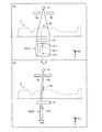
図3に示した例において、X線検出器14は、被検体Pの体軸方向(Z方向)に沿って320列に配列されたX線検出素子を有するものとする。調整部132は、図3(A)に示すように、最初はX線検出器14の開口度を調整する。かかる場合に、X線検出器14は、全てのX線検出素子(320列×Y方向の数)において被検体Pを透過したX線を検出する。これにより、画像再構成部141は、広範囲に被検体Pを透過したX線から、図3(A)に示したボリュームデータVD10を再構成する。なお、かかるボリュームデータVD10のうち、ボクセル群V11は、穿刺針23を示すものとする。
In the example shown in FIG. 3, the
続いて、取得部131は、ボリュームデータVD10から、穿刺針23の先端の位置を取得する。ここでは、取得部131は、図3(A)に示すように、穿刺針23を示すボクセル群V11の先端に位置するボクセルM11を穿刺針23の先端として特定する。すなわち、取得部131は、ボクセルM11が配置されている位置を穿刺針23の先端の位置として取得する。ここで、ボクセルM11は、XY平面に平行な断面A11上に配置されるものとする。
Subsequently, the
かかる場合に、調整部132は、断面A11からZ方向に前後N[mm]の範囲を照射範囲にすることを決定する。そして、調整部132は、図3(B)に示した例のように、決定した照射範囲にX線が照射されるように、コリメータ13bの開口度を調整する。これにより、X線検出器14は、断面A11からZ方向に前後N[mm]の範囲に含まれるX線検出素子において被検体Pを透過したX線を検出する。なお、上記「N」は、X線検出器14の列方向(Z方向)の長さの「1/2」よりも小さい値となる。すなわち、調整部132は、X線検出器14が有する全てのX線検出素子にX線が照射されない範囲で、コリメータ13bの開口度を調整する。そして、画像再構成部141は、かかるX線検出素子において検出されたX線から、図3(B)に示したボリュームデータVD20を再構成する。かかるボリュームデータVD20内のボクセル群V21は、穿刺針23を示すものとする。
In such a case, the
そして、レンダリング制御部133は、ボリュームデータVD20から複数の断面画像を生成するようにレンダリング処理部142を制御する。例えば、レンダリング制御部133は、XY平面と平行方向に切断した断面画像を複数生成するようにレンダリング処理部142を制御する。ここで、ボリュームデータVD20は、ボリュームデータVD10と比較して容量が小さいが、穿刺針23の先端を示すボクセルを含む。すなわち、レンダリング処理部142は、ボリュームデータVD20から、穿刺針23の先端を示す画像を含む断面画像を生成することができる。そして、表示制御部134は、レンダリング処理部142によって生成された複数の断面画像を表示部120に並列表示させる。
Then, the
ここで、図4に、第1の実施形態における表示部120に表示される複数の断面画像の一例を示す。図4に例示した3枚の断面画像I11、I12及びI13は、図3(B)に示したボリュームデータVD20から生成されたものとする。また、断面画像I11、I12及びI13は、穿刺針23の進行方向(Z軸の負方向)に沿ってボリュームデータVD20を切断した断面画像であり、断面画像I11、断面画像I12、断面画像I13の順に穿刺針23の進行先の断面画像を示すものとする。
Here, FIG. 4 shows an example of a plurality of cross-sectional images displayed on the
図4に示した例では、断面画像I11には穿刺針23を示す画像I11aが含まれており、また、断面画像I12には、穿刺針23を示す画像I12aが含まれる。一方、断面画像I13には穿刺針23を示す画像が含まれていない。これにより、観察者は、断面画像I12に対応する位置の近傍に穿刺針23の先端が到達していることを観察することができる。
In the example shown in FIG. 4, the cross-sectional image I11 includes an image I11a indicating the
なお、上記図4に示した例では、レンダリング制御部133が3枚の断面画像を生成するようにレンダリング処理部142を制御する例を示したが、レンダリング制御部133は、2枚や4枚以上の断面画像を生成するようにレンダリング処理部142を制御してもよい。また、レンダリング制御部133は、断面画像ではなく透視画像やMIP画像やMPR(Multi Planer Reconstruction)画像を生成するようにレンダリング処理部142を制御してもよい。
In the example illustrated in FIG. 4, the
システム制御部130は、図3を用いて説明した処理を繰り返し行う。具体的には、取得部131は、画像再構成部141によってボリュームデータが再構成されるたびに、穿刺針23の先端の位置を取得する。そして、調整部132は、取得部131によって取得された穿刺針23の先端の位置に基づいて、X線の照射範囲を新たに決定する。すなわち、調整部132は、穿刺針23の進行に伴って、X線の照射範囲を移動させる。そして、レンダリング制御部133は、レンダリング処理部142と協働して図4に例示したような断面画像を生成する。このようにして、システム制御部130は、穿刺針23を含む画像を略リアルタイムに表示部120に表示させる。
The
図3に示した例を用いて説明すると、例えば、医師等によって穿刺針23が図3(B)に示した状態よりも更に挿入されたとする。そして、図3(B)に示した照射範囲によりボリュームデータが再構成されたものとする。このボリュームデータ内のボクセル群のうち穿刺針23の先端を示すボクセルは、断面A11よりも左側(Z軸の負方向)に位置することになる。取得部131は、かかる穿刺針23の先端の位置を取得する。そして、調整部132は、取得部131によって取得された穿刺針23の先端の位置に基づいて、X線の照射範囲を穿刺針23の進行方向(Z軸の負方向)に移動させる。これにより、システム制御部130は、穿刺針23が移動した場合であっても、穿刺針23の先端が位置する領域にX線を照射することができ、この結果、穿刺針23の先端を含む断面画像を生成することができる。
If it demonstrates using the example shown in FIG. 3, suppose that the
次に、図5を用いて、第1の実施形態におけるX線CT装置1による処理の流れの一例を示す。図5は、第1の実施形態におけるX線CT装置1による処理の流れの一例を示すフローチャートである。 Next, an example of the flow of processing by the X-ray CT apparatus 1 in the first embodiment will be described with reference to FIG. FIG. 5 is a flowchart illustrating an example of a processing flow by the X-ray CT apparatus 1 according to the first embodiment.
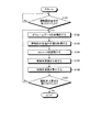
図5に示すように、X線CT装置1のシステム制御部130は、操作者から撮影開始要求を受け付けたか否かを判定する(ステップS101)。ここで、撮影開始要求を受け付けない場合には(ステップS101否定)、システム制御部130は、撮影開始要求を受け付けるまで待機する。一方、撮影開始要求を受け付けた場合には(ステップS101肯定)、画像再構成部141は、撮影処理を行うことによりボリュームデータを再構成する(ステップS102)。
As illustrated in FIG. 5, the
続いて、システム制御部130の取得部131は、画像再構成部141によって再構成されたボリュームデータを参照して、穿刺針23の先端の位置を取得する(ステップS103)。続いて、システム制御部130の調整部132は、取得部131によって取得された穿刺針23の先端近傍の範囲にX線が照射されるように、コリメータ13bの開口度を調整する(ステップS104)。
Subsequently, the
続いて、システム制御部130のレンダリング制御部133は、レンダリング処理部142と協働して、画像再構成部141によって再構成されたボリュームデータから透視画像や断面画像等の被検体画像を生成する(ステップS105)。そして、システム制御部130の表示制御部134は、レンダリング処理部142によって生成された被検体画像を表示部120に表示させる(ステップS106)。
Subsequently, the
そして、システム制御部130は、操作者から撮影終了要求を受け付けたか否かを判定する(ステップS107)。ここで、撮影終了要求を受け付けない場合には(ステップS107否定)、X線CT装置1は、ステップS102による処理手順に戻る。一方、撮影終了要求を受け付けた場合には(ステップS107肯定)、X線CT装置1は、処理を終了する。なお、図5に示した例では、ステップS106による処理手順の後に、ステップS107による処理手順が行われる例を示したが、X線CT装置1は、ステップS102〜S106の間においてもステップS107による処理手順を行う。
Then, the
上述してきたように、第1の実施形態によれば、穿刺針23が移動した場合であっても、穿刺針23の先端が位置する領域近傍のみにX線を照射することができ、この結果、穿刺針23の先端を含む画像を表示することができるとともに、被検体Pへの被曝量を低減することができる。
As described above, according to the first embodiment, even when the
(第2の実施形態)
上記第1の実施形態では、ボリュームデータから穿刺針を含む透視画像や断面画像を表示する例を示した。ここで、従来、2つの視点から撮影された2つの画像をモニタに表示することで、立体視用メガネ等の専用機器を用いた利用者にとって立体視可能な画像を表示する技術が知られている。また、近年、レンチキュラーレンズ等の光線制御子を用いて、複数の視点から撮影された画像(例えば、9つの画像)をモニタに表示することで、裸眼の利用者にとっても立体視可能な画像を表示する技術が知られている。そこで、第2の実施形態では、ボリュームデータから複数の視点に対応する視差画像を生成し、かかる視差画像を用いて利用者にとっても立体視可能な画像を表示する例について説明する。
(Second Embodiment)
In the first embodiment, an example is shown in which a fluoroscopic image and a cross-sectional image including a puncture needle are displayed from volume data. Here, conventionally, a technique for displaying a stereoscopically visible image for a user using dedicated equipment such as stereoscopic glasses by displaying two images taken from two viewpoints on a monitor is known. Yes. In recent years, an image captured from a plurality of viewpoints (for example, nine images) is displayed on a monitor using a light controller such as a lenticular lens, so that an image that can be stereoscopically viewed by a naked-eye user can be obtained. A technique for displaying is known. Therefore, in the second embodiment, an example will be described in which parallax images corresponding to a plurality of viewpoints are generated from volume data, and images that can be stereoscopically viewed by the user are displayed using the parallax images.
最初に、以下の実施形態で用いる用語について説明すると、「視差画像群」とは、ボリュームデータに対して、所定の視差角ずつ視点位置を移動させてボリュームレンダリング処理を行うことで生成された画像群のことである。すなわち、「視差画像群」は、「視点位置」が異なる複数の「視差画像」から構成される。また、「視差角」とは、「視差画像群」を生成するために設定された各視点位置のうち隣接する視点位置とボリュームデータによって表される空間内の所定位置(例えば、空間の中心)とにより定まる角度のことである。また、「視差数」とは、立体表示モニタにて立体視されるために必要となる「視差画像」の数のことである。また、以下で記載する「9視差画像」とは、9つの「視差画像」から構成される「視差画像群」のことである。また、以下で記載する「2視差画像」とは、2つの「視差画像」から構成される「視差画像群」のことである。 First, terms used in the following embodiments will be described. A “parallax image group” is an image generated by performing volume rendering processing by moving a viewpoint position by a predetermined parallax angle with respect to volume data. It is a group. That is, the “parallax image group” includes a plurality of “parallax images” having different “viewpoint positions”. The “parallax angle” is a predetermined position in the space represented by the volume data and an adjacent viewpoint position among the viewpoint positions set to generate the “parallax image group” (for example, the center of the space) It is an angle determined by. The “parallax number” is the number of “parallax images” necessary for stereoscopic viewing on the stereoscopic display monitor. The “9 parallax images” described below is a “parallax image group” composed of nine “parallax images”. The “two-parallax image” described below is a “parallax image group” composed of two “parallax images”.
次に、第2の実施形態におけるX線CT装置について説明するが、第2の実施形態におけるX線CT装置の構成は、図1に示したX線CT装置1の構成例と同様であるので、図示することを省略する。ただし、第2の実施形態におけるX線CT装置が有する表示部120は、立体視可能なモニタ(立体表示モニタ、立体画像表示装置とも称する)であり、各種情報を表示する。また、第2の実施形態におけるX線CT装置が有するレンダリング処理部142は、画像再構成部141によって生成されたボリュームデータに対して種々のレンダリング処理を行い、視差画像群を生成する。また、第2の実施形態におけるX線CT装置が有するシステム制御部(後述する「システム制御部230」)は、図2に示したシステム制御部130と異なる処理を行う。以下に、第2の実施形態における表示部120、レンダリング処理部142、システム制御部230について順に説明する。
Next, an X-ray CT apparatus according to the second embodiment will be described. The configuration of the X-ray CT apparatus according to the second embodiment is the same as the configuration example of the X-ray CT apparatus 1 shown in FIG. , Illustration is omitted. However, the
第2の実施形態における表示部120は、観察者にとって立体視可能な画像を表示することができる。例えば、表示部120は、記憶部150に記憶されているボリュームデータから生成された視差画像群などを表示することにより、観察者が立体的に視認可能な画像である立体画像を提供する。
The
ここで、立体表示モニタについて説明する。現在最も普及している一般的な汎用モニタは、2次元画像を2次元で表示するものであり、2次元画像を立体表示することができない。仮に、観察者が汎用モニタにて立体視を要望する場合、汎用モニタに対して画像を出力する装置は、平行法や交差法により観察者が立体視可能な2視差画像を並列表示させる必要がある。又は、汎用モニタに対して画像を出力する装置は、例えば、左目用の部分に赤色のセロハンが取り付けられ、右目用の部分に青色のセロハンが取り付けられたメガネを用いて余色法により観察者が立体視可能な画像を表示する必要がある。 Here, the stereoscopic display monitor will be described. A general-purpose monitor that is most popular at present displays a two-dimensional image in two dimensions, and cannot display a two-dimensional image in three dimensions. If an observer requests stereoscopic viewing on a general-purpose monitor, an apparatus that outputs an image to the general-purpose monitor needs to display two parallax images that can be viewed stereoscopically by the observer in parallel by the parallel method or the intersection method. is there. Alternatively, an apparatus that outputs an image to a general-purpose monitor, for example, uses an after-color method with an eyeglass that has a red cellophane attached to the left eye portion and a blue cellophane attached to the right eye portion. It is necessary to display a stereoscopically viewable image.
一方、立体表示モニタとしては、立体視用メガネ等の専用機器を用いることで、2視差画像(両眼視差画像とも称する)を立体視可能とするものがある。 On the other hand, as a stereoscopic display monitor, there is a stereoscopic display monitor that enables a stereoscopic view of a two-parallax image (also referred to as a binocular parallax image) by using dedicated equipment such as stereoscopic glasses.
図6は、2視差画像により立体表示を行う立体表示モニタの一例を説明するための図である。図6に示す一例は、シャッター方式により立体表示を行う立体表示モニタであり、モニタを観察する観察者が装着する立体視用メガネとしてシャッターメガネが用いられる。かかる立体表示モニタは、モニタにて2視差画像を交互に出射する。例えば、図6の(A)に示すモニタは、左目用の画像と右目用の画像を、120Hzにて交互に出射する。ここで、モニタには、図6の(A)に示すように、赤外線出射部が設置され、赤外線出射部は、画像が切り替わるタイミングに合わせて赤外線の出射を制御する。 FIG. 6 is a diagram for explaining an example of a stereoscopic display monitor that performs stereoscopic display using two parallax images. An example shown in FIG. 6 is a stereoscopic display monitor that performs stereoscopic display by a shutter method, and shutter glasses are used as stereoscopic glasses worn by an observer who observes the monitor. Such a stereoscopic display monitor emits two parallax images alternately on the monitor. For example, the monitor shown in FIG. 6A alternately emits a left-eye image and a right-eye image at 120 Hz. Here, as shown in FIG. 6A, the monitor is provided with an infrared emitting unit, and the infrared emitting unit controls the emission of infrared rays in accordance with the timing at which the image is switched.
また、赤外線出射部から出射された赤外線は、図6の(A)に示すシャッターメガネの赤外線受光部により受光される。シャッターメガネの左右それぞれの枠には、シャッターが取り付けられており、シャッターメガネは、赤外線受光部が赤外線を受光したタイミングに合わせて左右のシャッターそれぞれの透過状態及び遮光状態を交互に切り替える。以下、シャッターにおける透過状態及び遮光状態の切り替え処理について説明する。 Moreover, the infrared rays emitted from the infrared ray emitting portion are received by the infrared ray receiving portion of the shutter glasses shown in FIG. A shutter is attached to each of the left and right frames of the shutter glasses, and the shutter glasses alternately switch the transmission state and the light shielding state of the left and right shutters according to the timing when the infrared light receiving unit receives the infrared rays. Hereinafter, the switching process between the transmission state and the light shielding state in the shutter will be described.
各シャッターは、図6の(B)に示すように、入射側の偏光板と出射側の偏光板とを有し、更に、入射側の偏光板と出射側の偏光板との間に液晶層を有する。また、入射側の偏光板と出射側の偏光板とは、図6の(B)に示すように、互いに直交している。ここで、図6の(B)に示すように、電圧が印加されていない「OFF」の状態では、入射側の偏光板を通った光は、液晶層の作用により90度回転し、出射側の偏光板を透過する。すなわち、電圧が印加されていないシャッターは、透過状態となる。 As shown in FIG. 6B, each shutter has an incident-side polarizing plate and an output-side polarizing plate, and a liquid crystal layer between the incident-side polarizing plate and the output-side polarizing plate. Have Further, the polarizing plate on the incident side and the polarizing plate on the output side are orthogonal to each other as shown in FIG. Here, as shown in FIG. 6B, in the “OFF” state where no voltage is applied, the light that has passed through the polarizing plate on the incident side is rotated by 90 ° by the action of the liquid crystal layer, and is emitted on the outgoing side. Is transmitted through the polarizing plate. That is, a shutter to which no voltage is applied is in a transmissive state.
一方、図6の(B)に示すように、電圧が印加された「ON」の状態では、液晶層の液晶分子による偏光回転作用が消失するため、入射側の偏光板を通った光は、出射側の偏光板で遮られてしまう。すなわち、電圧が印加されたシャッターは、遮光状態となる。 On the other hand, as shown in FIG. 6B, in the “ON” state where a voltage is applied, the polarization rotation action caused by the liquid crystal molecules in the liquid crystal layer disappears. It will be blocked by the polarizing plate on the exit side. That is, the shutter to which the voltage is applied is in a light shielding state.
そこで、例えば、赤外線出射部は、モニタ上に左目用の画像が表示されている期間、赤外線を出射する。そして、赤外線受光部は、赤外線を受光している期間、左目のシャッターに電圧を印加せず、右目のシャッターに電圧を印加させる。これにより、図6の(A)に示すように、右目のシャッターが遮光状態となり、左目のシャッターが透過状態となるため、観察者の左目に左目用の画像が入射する。一方、赤外線出射部は、モニタ上に右目用の画像が表示されている期間、赤外線の出射を停止する。そして、赤外線受光部は、赤外線が受光されない期間、右目のシャッターに電圧を印加せず、左目のシャッターに電圧を印加させる。これにより、左目のシャッターが遮光状態となり、右目のシャッターが透過状態であるため、観察者の右目に右目用の画像が入射する。このように、図6に示す立体表示モニタは、モニタに表示される画像とシャッターの状態を連動させて切り替えることで、観察者が立体視可能な画像を表示させる。なお、2視差画像を立体視可能な立体表示モニタとしては、上記のシャッター方式以外にも、偏光メガネ方式を採用したモニタも知られている。 Therefore, for example, the infrared emitting unit emits infrared rays during a period in which an image for the left eye is displayed on the monitor. The infrared light receiving unit applies a voltage to the right-eye shutter without applying a voltage to the left-eye shutter during a period of receiving the infrared light. As a result, as shown in FIG. 6A, the right-eye shutter is in a light-shielding state and the left-eye shutter is in a transmissive state, so that an image for the left eye enters the left eye of the observer. On the other hand, the infrared ray emitting unit stops emitting infrared rays while the right-eye image is displayed on the monitor. The infrared light receiving unit applies a voltage to the left-eye shutter without applying a voltage to the right-eye shutter during a period in which no infrared light is received. Accordingly, the left-eye shutter is in a light-shielding state and the right-eye shutter is in a transmissive state, so that an image for the right eye enters the right eye of the observer. As described above, the stereoscopic display monitor illustrated in FIG. 6 displays an image that can be viewed stereoscopically by the observer by switching the image displayed on the monitor and the state of the shutter in conjunction with each other. As a stereoscopic display monitor capable of stereoscopically viewing a two-parallax image, a monitor adopting a polarized glasses method is also known in addition to the shutter method described above.
更に、近年実用化された立体表示モニタとしては、レンチキュラーレンズ等の光線制御子を用いることで、例えば、9視差画像等の多視差画像を観察者が裸眼にて立体視可能とするものがある。かかる立体表示モニタは、両眼視差による立体視を可能とし、更に、観察者の視点移動に合わせて観察される映像も変化する運動視差による立体視も可能とする。 Furthermore, as a stereoscopic display monitor that has been put into practical use in recent years, there is a stereoscopic display monitor that allows a viewer to stereoscopically view a multi-parallax image such as a 9-parallax image with the naked eye by using a light controller such as a lenticular lens. . Such a stereoscopic display monitor enables stereoscopic viewing based on binocular parallax, and also enables stereoscopic viewing based on motion parallax that also changes the image observed in accordance with the viewpoint movement of the observer.
図7は、9視差画像により立体表示を行う立体表示モニタの一例を説明するための図である。図7に示す立体表示モニタには、液晶パネル等の平面状の表示面200の前面に、光線制御子が配置される。例えば、図7に示す立体表示モニタには、光線制御子として、光学開口が垂直方向に延びる垂直レンチキュラーシート201が表示面200の前面に貼り付けられている。なお、図7に示す一例では、垂直レンチキュラーシート201の凸部が前面となるように貼り付けられているが、垂直レンチキュラーシート201の凸部が表示面200に対向するように貼り付けられる場合であってもよい。
FIG. 7 is a diagram for describing an example of a stereoscopic display monitor that performs stereoscopic display with nine parallax images. In the stereoscopic display monitor shown in FIG. 7, a light beam controller is arranged in front of a
表示面200には、図7に示すように、縦横比が3:1であり、縦方向にサブ画素である赤(R)、緑(G)、青(B)の3つが配置された画素202がマトリクス状に配置される。図7に示す立体表示モニタは、9つの画像により構成される9視差画像を、所定フォーマット(例えば格子状)に配置した中間画像に変換したうえで、表示面200に出力する。すなわち、図7に示す立体表示モニタは、9視差画像にて同一位置にある9つの画素それぞれを、9列の画素202に割り振って出力させる。9列の画素202は、視点位置の異なる9つの画像を同時に表示する単位画素群203となる。
As shown in FIG. 7, the
表示面200において単位画素群203として同時に出力された9視差画像は、例えば、LED(Light Emitting Diode)バックライトにより平行光として放射され、更に、垂直レンチキュラーシート201により、多方向に放射される。9視差画像の各画素の光が多方向に放射されることにより、観察者の右目及び左目に入射する光は、観察者の位置(視点の位置)に連動して変化する。すなわち、観察者の見る角度により、右目に入射する視差画像と左目に入射する視差画像とは、視差角が異なる。これにより、観察者は、例えば、図7に示す9つの位置それぞれにおいて、撮影対象を立体的に視認できる。また、観察者は、例えば、図7に示す「5」の位置において、撮影対象に対して正対した状態で立体的に視認できるとともに、図7に示す「5」以外それぞれの位置において、撮影対象の向きを変化させた状態で立体的に視認できる。なお、図7に示す立体表示モニタは、あくまでも一例である。9視差画像を表示する立体表示モニタは、図7に示すように、「RRR・・・、GGG・・・、BBB・・・」の横ストライプ液晶である場合であってもよいし、「RGBRGB・・・」の縦ストライプ液晶である場合であってもよい。また、図7に示す立体表示モニタは、図7に示すように、レンチキュラーシートが垂直となる縦レンズ方式である場合であってもよいし、レンチキュラーシートが斜めとなる斜めレンズ方式である場合であってもよい。
The nine parallax images simultaneously output as the
次に、第2の実施形態におけるレンダリング処理部142について説明する。第2の実施形態におけるレンダリング処理部142は、システム制御部230による制御の下、画像再構成部141によって生成されたボリュームデータに対して種々のレンダリング処理を行い、視差画像群を生成する。具体的には、第2の実施形態におけるレンダリング処理部142は、記憶部150からボリュームデータを読み込み、このボリュームデータに対して、まず前処理を行う。次に、レンダリング処理部142は、前処理後のボリュームデータに対してボリュームレンダリング処理を行い、視差画像群を生成する。
Next, the
また、レンダリング処理部142は、各種情報(目盛り、患者名、検査項目等)が描出された2次元画像を生成し、これを視差画像群それぞれに対して重畳することで、出力用の2次元画像を生成する。そして、レンダリング処理部142は、生成した視差画像群や出力用の2次元画像を記憶部150に格納する。
In addition, the
ここで、第2の実施形態におけるレンダリング処理部142の詳細について説明する。図8は、第2の実施形態におけるレンダリング処理部142の構成例を説明するための図である。図8に示すように、レンダリング処理部142は、前処理部1421と、3次元画像処理部1422と、2次元画像処理部1423とを有する。前処理部1421が、ボリュームデータに対する前処理を行い、3次元画像処理部1422が、前処理後のボリュームデータから視差画像群を生成し、2次元画像処理部1423が、視差画像群に各種情報が重畳された出力用の2次元画像を生成する。以下、各部を順に説明する。
Here, details of the
前処理部1421は、ボリュームデータに対してレンダリング処理を行う際に、種々の前処理を行う処理部であり、画像補正処理部1421aと、3次元物体フュージョン部1421eと、3次元物体表示領域設定部1421fとを有する。
The
画像補正処理部1421aは、2種類のボリュームデータを1つのボリュームデータとして処理する際に画像補正処理を行う処理部であり、図8に示すように、歪み補正処理部1421b、体動補正処理部1421c及び画像間位置合わせ処理部1421dを有する。
The image correction processing unit 1421a is a processing unit that performs image correction processing when processing two types of volume data as one volume data, and as illustrated in FIG. 8, a distortion
歪み補正処理部1421bは、個々のボリュームデータにおいて、データ収集時の収集条件に起因するデータの歪みを補正する。体動補正処理部1421cは、個々のボリュームデータを生成するために用いられたデータの収集時期における被検体Pの体動に起因する移動を補正する。画像間位置合わせ処理部1421dは、歪み補正処理部1421b及び体動補正処理部1421cによる補正処理が行われた2つのボリュームデータ間で、例えば、相互相関法等を用いた位置合わせ(Registration)を行う。
The distortion
3次元物体フュージョン部1421eは、画像間位置合わせ処理部1421dにより位置合わせが行われた複数のボリュームデータをフュージョンさせる。なお、画像補正処理部1421a及び3次元物体フュージョン部1421eの処理は、単一のボリュームデータに対してレンダリング処理を行う場合、省略される。
The three-dimensional
3次元物体表示領域設定部1421fは、操作者により指定された表示対象臓器に対応する表示領域を設定する処理部であり、セグメンテーション処理部1421gを有する。セグメンテーション処理部1421gは、操作者により指定された心臓、肺、血管等の臓器を、例えば、ボリュームデータの画素値(ボクセル値)に基づく領域拡張法により抽出する処理部である。
The three-dimensional object display
なお、セグメンテーション処理部1421gは、操作者により表示対象臓器が指定されなかった場合、セグメンテーション処理を行わない。また、セグメンテーション処理部1421gは、操作者により表示対象臓器が複数指定された場合、該当する複数の臓器を抽出する。また、セグメンテーション処理部1421gの処理は、レンダリング画像を参照した操作者の微調整要求により再度実行される場合もある。
Note that the
3次元画像処理部1422は、前処理部1421が処理を行った前処理後のボリュームデータに対してボリュームレンダリング処理を行う。ボリュームレンダリング処理を行う処理部として、3次元画像処理部1422は、投影方法設定部1422aと、3次元幾何変換処理部1422bと、3次元物体アピアランス処理部1422fと、3次元仮想空間レンダリング部1422kとを有する。
The 3D
投影方法設定部1422aは、視差画像群を生成するための投影方法を決定する。例えば、投影方法設定部1422aは、ボリュームレンダリング処理を平行投影法により実行するか、透視投影法により実行するかを決定する。 The projection method setting unit 1422a determines a projection method for generating a parallax image group. For example, the projection method setting unit 1422a determines whether to execute the volume rendering process by the parallel projection method or the perspective projection method.
3次元幾何変換処理部1422bは、ボリュームレンダリング処理が実行されるボリュームデータを3次元幾何学的に変換するための情報を決定する処理部であり、平行移動処理部1422c、回転処理部1422d及び拡大縮小処理部1422eを有する。平行移動処理部1422cは、ボリュームレンダリング処理を行う際の視点位置が平行移動された場合に、ボリュームデータを平行移動させる移動量を決定する処理部であり、回転処理部1422dは、ボリュームレンダリング処理を行う際の視点位置が回転移動された場合に、ボリュームデータを回転移動させる移動量を決定する処理部である。また、拡大縮小処理部1422eは、視差画像群の拡大や縮小が要求された場合に、ボリュームデータの拡大率や縮小率を決定する処理部である。 The three-dimensional geometric transformation processing unit 1422b is a processing unit that determines information for three-dimensional geometric transformation of volume data for which volume rendering processing is performed, and includes a translation processing unit 1422c, a rotation processing unit 1422d, and an enlargement. A reduction processing unit 1422e is included. The translation processing unit 1422c is a processing unit that determines the amount of movement to translate the volume data when the viewpoint position when performing the volume rendering process is translated, and the rotation processing unit 1422d performs the volume rendering process. This is a processing unit that determines the amount of movement to rotate the volume data when the viewpoint position at the time of rotation is rotated. The enlargement / reduction processing unit 1422e is a processing unit that determines the enlargement rate or reduction rate of the volume data when enlargement or reduction of the parallax image group is requested.
3次元物体アピアランス処理部1422fは、3次元物体色彩処理部1422g、3次元物体不透明度処理部1422h、3次元物体材質処理部1422i及び3次元仮想空間光源処理部1422jを有する。3次元物体アピアランス処理部1422fは、これらの処理部により、例えば、後述するシステム制御部230による制御に基づいて、表示される視差画像群の表示状態を決定する処理を行う。
The three-dimensional object
3次元物体色彩処理部1422gは、ボリュームデータにてセグメンテーションされた各領域に対して着色される色彩を決定する処理部である。3次元物体不透明度処理部1422hは、ボリュームデータにてセグメンテーションされた各領域を構成する各ボクセルの不透過度(Opacity)を決定する処理部である。なお、ボリュームデータにおいて不透過度が「100%」とされた領域の後方の領域は、視差画像群において描出されないこととなる。また、ボリュームデータにおいて不透過度が「0%」とされた領域は、視差画像群において描出されないこととなる。 The three-dimensional object color processing unit 1422g is a processing unit that determines a color to be colored for each region segmented by the volume data. The three-dimensional object opacity processing unit 1422h is a processing unit that determines the opacity (Opacity) of each voxel constituting each region segmented by volume data. It should be noted that the area behind the area having the opacity of “100%” in the volume data is not drawn in the parallax image group. In addition, an area in which the opacity is “0%” in the volume data is not drawn in the parallax image group.
3次元物体材質処理部1422iは、ボリュームデータにてセグメンテーションされた各領域の材質を決定することで、この領域が描出される際の質感を調整する処理部である。3次元仮想空間光源処理部1422jは、ボリュームデータに対してボリュームレンダリング処理を行う際に、3次元仮想空間に設置する仮想光源の位置や、仮想光源の種類を決定する処理部である。仮想光源の種類としては、無限遠から平行な光線を照射する光源や、視点から放射状の光線を照射する光源等が挙げられる。
The three-dimensional object
3次元仮想空間レンダリング部1422kは、ボリュームデータに対してボリュームレンダリング処理を行い、視差画像群を生成する。また、3次元仮想空間レンダリング部1422kは、ボリュームレンダリング処理を行う際、必要に応じて、投影方法設定部1422a、3次元幾何変換処理部1422b、3次元物体アピアランス処理部1422fにより決定された各種情報を用いる。
The three-dimensional virtual
ここで、3次元仮想空間レンダリング部1422kによるボリュームレンダリング処理は、レンダリング条件に従って行われることになる。例えば、レンダリング条件は、「平行投影法」又は「透視投影法」である。また、例えば、レンダリング条件は、「基準の視点位置及び視差角」である。また、例えば、レンダリング条件は、「視点位置の平行移動」、「視点位置の回転移動」、「視差画像群の拡大」、「視差画像群の縮小」である。また、例えば、レンダリング条件は、「着色される色彩」、「透過度」、「質感」、「仮想光源の位置」、「仮想光源の種類」である。
Here, the volume rendering process by the three-dimensional virtual
このようなレンダリング条件は、入力部110を介して操作者から受け付けたり、初期設定されたり、システム制御部230によって決定される。いずれの場合も、3次元仮想空間レンダリング部1422kは、システム制御部230からレンダリング条件を受け付け、このレンダリング条件に従って、ボリュームデータに対するボリュームレンダリング処理を行う。また、このとき、上述した投影方法設定部1422a、3次元幾何変換処理部1422b、3次元物体アピアランス処理部1422fが、このレンダリング条件に従って必要な各種情報を決定するので、3次元仮想空間レンダリング部1422kは、決定されたこれらの各種情報を用いて視差画像群を生成する。
Such rendering conditions are accepted from the operator via the
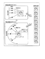
図9は、第2の実施形態におけるボリュームレンダリング処理の一例を説明するための図である。例えば、3次元仮想空間レンダリング部1422kが、図9の「9視差画像生成方式(1)」に示すように、レンダリング条件として、平行投影法を受け付け、更に、基準の視点位置(5)と視差角「1度」とを受け付けたとする。かかる場合、3次元仮想空間レンダリング部1422kは、視差角が「1度」おきとなるように、視点の位置を(1)〜(9)に平行移動して、平行投影法により視差角(視線方向間の角度)が1度ずつ異なる9つの視差画像を生成する。なお、平行投影法を行う場合、3次元仮想空間レンダリング部1422kは、視線方向に沿って無限遠から平行な光線を照射する光源を設定する。
FIG. 9 is a diagram for explaining an example of volume rendering processing according to the second embodiment. For example, as shown in “9-parallax image generation method (1)” in FIG. 9, the three-dimensional virtual
或いは、3次元仮想空間レンダリング部1422kが、図9の「9視差画像生成方式(2)」に示すように、レンダリング条件として、透視投影法を受け付け、更に、基準の視点位置(5)と視差角「1度」とを受け付けたとする。かかる場合、3次元仮想空間レンダリング部1422kは、ボリュームデータの中心(重心)を中心に視差角が「1度」おきとなるように、視点の位置を(1)〜(9)に回転移動して、透視投影法により視差角が1度ずつ異なる9つの視差画像を生成する。なお、透視投影法を行う場合、3次元仮想空間レンダリング部1422kは、視線方向を中心に光を3次元的に放射状に照射する点光源や面光源を各視点にて設定する。また、透視投影法を行う場合、レンダリング条件によっては、視点(1)〜(9)は、平行移動される場合であってもよい。なお、視線方向は、図9の(A)及び(B)に示すように、視点からボリュームデータの切断面の中心(重心)に向かう方向となる。
Alternatively, as shown in “9-parallax image generation method (2)” in FIG. 9, the three-dimensional virtual
なお、3次元仮想空間レンダリング部1422kは、表示されるボリュームレンダリング画像の縦方向に対しては、視線方向を中心に光を2次元的に放射状に照射し、表示されるボリュームレンダリング画像の横方向に対しては、視線方向に沿って無限遠から平行な光線を照射する光源を設定することで、平行投影法と透視投影法とを併用したボリュームレンダリング処理を行ってもよい。
Note that the three-dimensional virtual
また、3次元仮想空間レンダリング部1422kは、ボリュームレンダリングだけでなく、断面再構成法(MPR)を行うことで、ボリュームデータからMPR画像を再構成する機能も有する。また、3次元仮想空間レンダリング部1422kは、MPRとして「Curved MPR」を行う機能や、「Intensity Projection」を行う機能も有する。
The three-dimensional virtual
また、3次元画像処理部1422がボリュームデータから生成した視差画像群は、アンダーレイ(Underlay)とされる。そして、各種情報(目盛り、患者名、検査項目等)が描出されたオーバーレイ(Overlay)がアンダーレイに対して重畳されることで、出力用の2次元画像とされる。2次元画像処理部1423は、オーバーレイ及びアンダーレイに対して画像処理を行うことで、出力用の2次元画像を生成する処理部であり、図8に示すように、2次元物体描画部1423a、2次元幾何変換処理部1423b及び輝度調整部1423cを有する。例えば、2次元画像処理部1423は、出力用の2次元画像の生成処理に要する負荷を軽減するために、9枚の視差画像(アンダーレイ)のそれぞれに対して1枚のオーバーレイを重畳することで、出力用の2次元画像を9枚生成する。なお、以下では、オーバーレイが重畳されたアンダーレイを単に「視差画像」と表記する場合もある。
Further, the parallax image group generated from the volume data by the three-dimensional
2次元物体描画部1423aは、オーバーレイに描出される各種情報を描画する処理部であり、2次元幾何変換処理部1423bは、オーバーレイに描出される各種情報の位置を平行移動処理又は回転移動処理したり、オーバーレイに描出される各種情報の拡大処理又は縮小処理したりする処理部である。輝度調整部1423cは、輝度変換処理を行う処理部であり、例えば、出力先の立体表示モニタの諧調や、ウィンドウ幅(WW:Window Width)、ウィンドウレベル(WL:Window Level)等の画像処理用のパラメータに応じて、オーバーレイ及びアンダーレイの輝度を調整する処理部である。
The two-dimensional object drawing unit 1423a is a processing unit that draws various types of information drawn on the overlay, and the two-dimensional geometric transformation processing unit 1423b performs a parallel movement process or a rotational movement process on the position of the various types of information drawn on the overlay. Or a processing unit that performs an enlargement process or a reduction process of various types of information drawn on the overlay. The
レンダリング処理部142により生成された視差画像群は、記憶部150に格納される。その後、例えば、X線CT装置1は、オーバーレイ画像が重畳された視差画像群を所定フォーマット(例えば格子状)に配置した中間画像に変換した上で立体表示モニタに表示することで、利用者である医師や検査技師に、各種情報(目盛り、患者名、検査項目等)が描出された立体画像を表示可能となる。
The parallax image group generated by the
次に、図10を用いて、第2の実施形態におけるシステム制御部230について説明する。図10は、第2の実施形態におけるシステム制御部230の構成例を説明するための図である。図10に例示するように、第2の実施形態におけるシステム制御部230は、取得部131と、調整部132と、レンダリング制御部233と、表示制御部234とを有する。
Next, the system control unit 230 in the second embodiment will be described with reference to FIG. FIG. 10 is a diagram for explaining a configuration example of the system control unit 230 in the second embodiment. As illustrated in FIG. 10, the system control unit 230 in the second embodiment includes an
取得部131は、第1の実施形態において説明したように、画像再構成部141によって再構成されたボリュームデータ内のボクセル群から穿刺針23を示すボクセルを特定することにより、被検体Pの内部に存在する穿刺針23の先端の位置を取得する。
As described in the first embodiment, the acquiring
調整部132は、第1の実施形態において説明したように、取得部131によって取得された穿刺針23の先端近傍の範囲にX線が照射されるように、コリメータ13bの開口度を調整する。
As described in the first embodiment, the
レンダリング制御部233は、レンダリング処理部142と協働して、画像再構成部141によって再構成されたボリュームデータから視差画像群を生成する。第2の実施形態におけるレンダリング制御部233は、調整部132によってコリメータ13bが調整される前に再構成されたボリュームデータを保持しておく。具体的には、レンダリング制御部233は、X線検出器14が有する略全てのX線検出素子によって検出されたX線から再構成されたボリュームデータを保持しておく。そして、レンダリング制御部233は、画像再構成部141によってボリュームデータが新たに再構成されるたびに、保持しておいたボリュームデータを新たに再構成されたボリュームデータに更新する。このとき、レンダリング制御部233は、保持しておいたボリュームデータのうち、新たに再構成されたボリュームデータに対応する領域のみを更新する。なお、レンダリング制御部233による処理については、図11を用いて後述する。
The
表示制御部234は、レンダリング制御部233及びレンダリング処理部142によって生成される視差画像群を表示部120に表示させる。これにより、表示部120は、観察者にとって立体視可能な画像である立体画像を表示することができる。
The
次に、図11を用いて、上述したシステム制御部230による処理の一例を説明する。図11は、第2の実施形態におけるシステム制御部230による処理の一例を説明するための図である。 Next, an example of processing by the system control unit 230 described above will be described with reference to FIG. FIG. 11 is a diagram for explaining an example of processing performed by the system control unit 230 in the second embodiment.
まず、X線検出器14は、被検体Pの体軸方向(Z方向)に沿って320列に配列されたX線検出素子を有するものとする。そして、調整部132は、図3(A)に示した例と同様に、最初はX線検出器14の全検出面にX線が照射されるようにコリメータ13bの開口度を調整する。これにより、画像再構成部141は、広範囲に被検体Pを透過したX線から、図11(A)に示したボリュームデータVD30を再構成する。なお、かかるボリュームデータVD30は、図3(A)に例示したボリュームデータVD10と同様のサイズである。また、ボリュームデータVD30のうち、ボクセル群V31は、穿刺針23を示すものとする。
First, the
続いて、取得部131は、ボリュームデータVD30から、穿刺針23の先端の位置を取得する。ここでは、取得部131は、図11(B)に示すように、ボクセル群V31の先端に位置するボクセルM31を穿刺針23の先端として特定する。ここで、ボクセルM31は、XY平面に平行な断面A31上に配置されるものとする。かかる場合に、調整部132は、断面A31からZ方向に前後N[mm]の範囲を照射範囲にすることを決定し、決定した照射範囲にX線が照射されるように、コリメータ13bの開口度を調整する。これにより、画像再構成部141は、図11(B)に示したボリュームデータVD31を再構成する。
Subsequently, the
そして、第2の実施形態におけるレンダリング制御部233は、図11(A)に示したボリュームデータVD30のうち断面A31からZ方向に前後N[mm]の領域をボリュームデータVD31に置き換える。これにより、レンダリング制御部233は、図11(C)に示すように、ボリュームデータVD40を生成する。すなわち、ボリュームデータVD40のうち、領域R1及びR2は、図11(A)に示したボリュームデータVD30となり、領域R3は、図11(B)に示したボリュームデータVD31となる。
Then, the
そして、レンダリング制御部233は、このようにして生成したボリュームデータVD40に対してレンダリング処理を行うようにレンダリング処理部142を制御する。なお、視点位置や視差角等のレンダリング条件については、観察者によって予め設定されているものとする。これにより、レンダリング処理部142は、ボリュームデータVD40から視差画像群を生成する。そして、表示制御部234は、レンダリング処理部142によって生成された視差画像群を立体視可能なモニタである表示部120に表示させる。
Then, the
この後、図11(D)に示すように、医師等によって穿刺針23が更に挿入されたとする。そして、取得部131が、XY平面に平行な断面A41上に配置されるボクセルの位置を穿刺針23の先端の位置として取得したものとする。このとき、画像再構成部141は、図11(D)に示したボリュームデータVD41を再構成する。かかる場合に、レンダリング制御部233は、図11(C)に示したボリュームデータVD40のうち断面A41からZ方向に前後N[mm]の領域をボリュームデータVD41に置き換える。これにより、レンダリング制御部233は、ボリュームデータVD50(図示省略)を生成する。
Thereafter, as shown in FIG. 11D, it is assumed that the
このように、レンダリング制御部233は、画像再構成部141によって新たなボリュームデータが再構成されるたびに、再構成済みのボリュームデータに対して、新たなボリュームデータを順次更新する。これにより、レンダリング制御部233は、穿刺針23が移動した場合であっても、穿刺針23の先端を示すボクセルを含むボリュームデータを生成することができる。この結果、レンダリング処理部142は、穿刺針23の先端を含む視差画像群を生成することができる。
In this way, the
ここで、図12に、第2の実施形態における表示部120に表示される立体画像の一例を示す。図12に示した例において、表示部120は、上記ボリュームデータVD40から生成された視差画像群を用いて立体画像I21を表示し、上記ボリュームデータVD50から生成された視差画像群を用いて立体画像I22を表示するものとする。このように、表示部120は、レンダリング処理部142によって視差画像群が生成されるたびに、時系列に沿って視差画像群を表示することで、立体画像I21を表示した後に立体画像I22を表示する。これにより、表示部120は、穿刺針23を含む立体画像を略リアルタイムに表示することができる。
Here, FIG. 12 shows an example of a stereoscopic image displayed on the
図12に示した例では、立体画像I21には穿刺針23を示す立体画像I21aが含まれており、立体画像I22には穿刺針23を示す立体画像I22aが含まれている。医師等の観察者は、このような穿刺針23を示す立体画像の位置変動に基づいて、穿刺針23の先端が到達している部位を観察することができる。
In the example shown in FIG. 12, the stereoscopic image I21 includes a stereoscopic image I21a indicating the
なお、図12(A)に示した立体画像I21のうち領域R21の立体画像は、図11に示したボリュームデータVD31に対応し、立体画像I22のうち領域R22の立体画像は、図11に示したボリュームデータVD41に対応する。 The stereoscopic image in the region R21 in the stereoscopic image I21 shown in FIG. 12A corresponds to the volume data VD31 shown in FIG. 11, and the stereoscopic image in the region R22 in the stereoscopic image I22 is shown in FIG. Corresponds to the volume data VD41.
次に、図13を用いて、第2の実施形態におけるX線CT装置による処理の流れの一例を示す。図13は、第2の実施形態におけるX線CT装置による処理の流れの一例を示すフローチャートである。 Next, an example of the flow of processing by the X-ray CT apparatus in the second embodiment will be shown using FIG. FIG. 13 is a flowchart illustrating an example of a flow of processing by the X-ray CT apparatus according to the second embodiment.
図13に示すように、第2の実施形態におけるX線CT装置のシステム制御部230は、操作者から撮影開始要求を受け付けたか否かを判定する(ステップS201)。ここで、撮影開始要求を受け付けない場合には(ステップS201否定)、システム制御部230は、撮影開始要求を受け付けるまで待機する。一方、撮影開始要求を受け付けた場合には(ステップS201肯定)、画像再構成部141は、撮影処理を行うことによりボリュームデータを再構成する(ステップS202)。
As illustrated in FIG. 13, the system control unit 230 of the X-ray CT apparatus according to the second embodiment determines whether an imaging start request has been received from the operator (step S201). If the imaging start request is not accepted (No at Step S201), the system control unit 230 waits until the imaging start request is accepted. On the other hand, when an imaging start request is received (Yes at Step S201), the
続いて、システム制御部230の取得部131は、画像再構成部141によって再構成されたボリュームデータを参照して、穿刺針23の先端の位置を取得する(ステップS203)。続いて、システム制御部230の調整部132は、取得部131によって取得された穿刺針23の先端近傍の範囲にX線が照射されるように、コリメータ13bの開口度を調整する(ステップS204)。
Subsequently, the
続いて、システム制御部230のレンダリング制御部233は、再構成済みのボリュームデータが存在するか否かを判定する(ステップS205)。ここで、最初に被検体Pを撮影した状態である場合には、再構成済みのボリュームデータが存在しない。例えば、調整部132によってコリメータ13bが調整される前に被検体Pが広範囲に撮影された状態においては、再構成済みのボリュームデータが存在しない。一方、調整部132によってX線の照射範囲が制限された状態においては、再構成済みのボリュームデータ(例えば、被検体Pを広範囲に撮影することで生成されたボリュームデータ)が存在することになる。
Subsequently, the
レンダリング制御部233は、再構成済みのボリュームデータが存在する場合には(ステップS205肯定)、再構成済みのボリュームデータに対して、ステップS202において再構成されたボリュームデータを更新する(ステップS206)。一方、レンダリング制御部233は、再構成済みのボリュームデータが存在しない場合には(ステップS205否定)、ボリュームデータの更新処理を行わない。
If the reconfigured volume data exists (Yes at Step S205), the
そして、レンダリング制御部233は、レンダリング処理部142と協働してボリュームデータから視差画像群を生成する(ステップS207)。そして、システム制御部230の表示制御部234は、レンダリング処理部142によって生成された視差画像群を表示部120に表示させる(ステップS208)。
Then, the
そして、システム制御部230は、操作者から撮影終了要求を受け付けたか否かを判定する(ステップS209)。ここで、撮影終了要求を受け付けない場合には(ステップS209否定)、第2の実施形態におけるX線CT装置は、ステップS202による処理手順に戻る。一方、撮影終了要求を受け付けた場合には(ステップS209肯定)、第2の実施形態におけるX線CT装置は、処理を終了する。なお、図13に示した例では、ステップS208による処理手順の後に、ステップS209による処理手順が行われる例を示したが、第2の実施形態におけるX線CT装置は、ステップS202〜S208の間においてもステップS209による処理手順を行う。 Then, the system control unit 230 determines whether or not a photographing end request has been received from the operator (step S209). Here, when the imaging end request is not accepted (No at Step S209), the X-ray CT apparatus according to the second embodiment returns to the processing procedure at Step S202. On the other hand, when an imaging end request is received (Yes at step S209), the X-ray CT apparatus in the second embodiment ends the process. In the example illustrated in FIG. 13, the example in which the processing procedure in step S209 is performed after the processing procedure in step S208 is illustrated. However, the X-ray CT apparatus according to the second embodiment performs the processing between steps S202 to S208. In step S209, the processing procedure in step S209 is performed.
上述してきたように、第2の実施形態によれば、データサイズの大きいボリュームデータを用いる場合であっても、穿刺針23の先端が位置する領域近傍のみにX線を照射することができ、さらに、データサイズの大きいボリュームデータを更新することができる。この結果、第2の実施形態によれば、穿刺針23の先端を含む画像を表示することができるとともに、被検体Pへの被曝量を低減することができる。
As described above, according to the second embodiment, even when volume data with a large data size is used, X-rays can be irradiated only in the vicinity of the region where the tip of the
なお、上記第1及び第2の実施形態では、広範囲に被検体Pを透過したX線を検出することができるX線検出器14を例に挙げて説明した。しかし、第1又は第2におけるX線CT装置は、広範囲にX線を検出することができるX線検出器14を有しなくてもよい。すなわち、上述した第1又は第2におけるX線CT装置は、X線を検出することができる範囲が狭いX線検出器を有する場合にも適用することができる。
In the first and second embodiments, the
また、上記第2の実施形態では、ボリュームデータが再構成されるたびに、再構成済みのボリュームデータに対して、新たに再構成されたボリュームデータを累積的に反映する例を示した。しかし、上記第2の実施形態におけるレンダリング制御部233は、コリメータ13bが調整される前に再構成されたボリュームデータに対して、新たに再構成されたボリュームデータを反映してもよい。図11に示した例を用いて説明すると、レンダリング制御部233は、ボリュームデータVD31が再構成された場合に、ボリュームデータVD30にボリュームデータVD31を反映することで、ボリュームデータVD40を生成する。続いて、レンダリング制御部233は、ボリュームデータVD41が再構成された場合に、ボリュームデータVD40ではなくボリュームデータVD30に対して、ボリュームデータVD41を反映することで、ボリュームデータVD50を生成する。
In the second embodiment, an example in which the newly reconfigured volume data is cumulatively reflected on the reconfigured volume data every time the volume data is reconfigured is shown. However, the
また、上記第2の実施形態におけるX線CT装置は、定期的に、被検体Pを広範囲に透過したX線からボリュームデータを再構成してもよい。具体的には、図11に示した例では、レンダリング制御部233は、X線の照射範囲が制限されずに再構成されたボリュームデータVD30に対して、X線の照射範囲が制限された状態で再構成されたボリュームデータVD31やボリュームデータVD41を反映した。ここで、X線CT装置は、X線の照射範囲を制限せずに、ボリュームデータVD30と同様のデータサイズを有するボリュームデータを定期的に再構成してもよい。これは、ボリュームデータVD30のうち所定の時間更新されない領域が、被検体Pのリアルタイムな情報とならない可能性があるからである。すなわち、所定の時間更新されない領域と、順次更新される領域とは時相のことなる被検体Pを示す情報となるので、表示部120に表示される被検体Pの画像にずれが生じる可能性がある。上記のように、被検体Pを広範囲に透過したX線からボリュームデータを再構成する処理を定期的に行うことで、X線CT装置は、被検体Pの画像にずれが生じることを防止できる。
In addition, the X-ray CT apparatus in the second embodiment may periodically reconstruct volume data from X-rays that have passed through the subject P over a wide range. Specifically, in the example illustrated in FIG. 11, the
なお、X線CT装置は、ボリュームデータ全体を再構成する処理を定期的に行わなくてもよい。例えば、X線CT装置は、被検体Pに装着された呼吸センサ等が被検体Pの動きを検知した場合に、ボリュームデータ全体を再構成する処理を行ってもよい。また、X線CT装置は、観察者から要求があった場合に、ボリュームデータ全体を再構成する処理を行ってもよい。 Note that the X-ray CT apparatus may not periodically perform processing for reconstructing the entire volume data. For example, the X-ray CT apparatus may perform processing for reconstructing the entire volume data when a respiration sensor or the like attached to the subject P detects movement of the subject P. Further, the X-ray CT apparatus may perform processing for reconstructing the entire volume data when requested by the observer.
(第3の実施形態)
上記第2の実施形態では、被検体Pを載置する寝台装置20が固定されることを前提として説明した。しかし、寝台装置20は、医師等の観察者によって移動される場合がある。第3の実施形態では、寝台装置20が移動される場合について説明する。
(Third embodiment)
The second embodiment has been described on the assumption that the
なお、以下に説明する第3の実施形態におけるX線CT装置は、第2の実施形態におけるX線CT装置が有するX線検出器14と比較して、被検体Pの体軸方向(Z方向)に沿って配列されるX線検出素子の列数が少ないX線検出器24を有するものとする。このような第3の実施形態におけるX線CT装置は、X線の照射範囲が狭いので被検体Pへの被曝量が少ないものの、被曝量をさらに低減するために、穿刺針23の先端の位置に応じてコリメータ13bを調整する。ただし、穿刺針23の先端の位置を取得し、コリメータ13bを調整する処理については、上記第2の実施形態におけるX線CT装置による処理と同様であるので、以下では説明を省略する。第3の実施形態においては、寝台装置20の移動時におけるボリュームデータの生成処理を主に説明する。
Note that the X-ray CT apparatus in the third embodiment described below has a body axis direction (Z direction) of the subject P as compared with the
まず、第3の実施形態におけるシステム制御部330について説明するが、かかるシステム制御部330は、図10に示したシステム制御部230に対応する。ただし、第3の実施形態におけるシステム制御部330は、システム制御部230が有するレンダリング制御部233と異なる処理を行う。そこで、システム制御部330は、システム制御部230が有するレンダリング制御部233の代わりにレンダリング制御部333を有する。
First, the system control unit 330 according to the third embodiment will be described. The system control unit 330 corresponds to the system control unit 230 illustrated in FIG. However, the system control unit 330 in the third embodiment performs processing different from the
図14及び図15を用いて、第3の実施形態におけるシステム制御部330による処理の一例について説明する。図14及び図15は、第3の実施形態におけるシステム制御部330による処理の一例を説明するための図である。 An example of processing by the system control unit 330 in the third embodiment will be described with reference to FIGS. 14 and 15. 14 and 15 are diagrams for explaining an example of processing performed by the system control unit 330 according to the third embodiment.
図14に示すように、第3の実施形態におけるX線CT装置は、X線検出器24を有する。かかるX線検出器24は、第2の実施形態におけるX線検出器14と比較して、被検体Pの体軸方向(Z方向)に沿って配列されるX線検出素子の数が少ない。したがって、図14(A)に示すように、X線検出器24によって検出されたX線から再構成されるボリュームデータVD61は、第2の実施形態において説明したボリュームデータVD30等(図11参照)よりも、被検体Pの体軸方向(Z方向)のサイズが小さい。
As shown in FIG. 14, the X-ray CT apparatus in the third embodiment has an
ここで、穿刺針23が被検体Pの体軸方向に挿入された場合には、X線検出器24が検出できる範囲内で穿刺針23を撮影できない場合がある。なお、図14(A)では、X線検出器24の全検出面にX線が照射されるようにコリメータ13bが調整されている例を示しているが、X線の照射範囲が狭くなるように、コリメータ13bが調整されていてもよい。かかる場合においても、穿刺針23が被検体Pの体軸方向に挿入された際に、X線検出器24が穿刺針23を透過したX線を検出できない場合がある。このような場合に、医師等の観察者は、図14(B)に示すように、穿刺針23を撮影できるように、寝台装置20を移動させる。これにより、X線CT装置の画像再構成部141は、ボリュームデータVD62を生成する。
Here, when the
第3の実施形態におけるレンダリング制御部333は、このようにして再構成されたボリュームデータVD61及びVD62を合成する。かかる合成処理について、図15を用いて説明する。図15に示すように、レンダリング制御部333は、画像再構成部141によって再構成されたボリュームデータを配置するための仮想的な3次元空間(以下、「仮想ボリュームデータ空間」と表記する場合がある)SP10を形成する。かかる仮想ボリュームデータ空間SP10は、寝台装置20とともに移動する空間であり、寝台装置20の所定の基準位置を原点とする座標系によって表される。すなわち、レンダリング制御部333は、寝台装置20に移動に伴って、仮想ボリュームデータ空間SP10に配置するボリュームデータの位置を変更する。具体的には、レンダリング制御部333は、寝台装置20がZ軸の正方向に移動された場合、仮想ボリュームデータ空間SP10に配置するボリュームデータの位置をZ軸の負方向に移動させる。
The rendering control unit 333 in the third embodiment combines the volume data VD61 and VD62 reconstructed in this way. Such a synthesis process will be described with reference to FIG. As illustrated in FIG. 15, the rendering control unit 333 may be referred to as a virtual three-dimensional space (hereinafter referred to as “virtual volume data space”) for arranging the volume data reconstructed by the
例えば、図15に示した例において、レンダリング制御部333は、図14(A)に示した状態で再構成されたボリュームデータVD61を仮想ボリュームデータ空間SP10に配置する。そして、レンダリング制御部333は、図14(B)に示した状態でボリュームデータVD62が再構成された場合に、仮想ボリュームデータ空間SP10にボリュームデータVD62を配置する。このとき、レンダリング制御部333は、ボリュームデータVD61よりもZ軸の負方向の位置にボリュームデータVD62を配置する。 For example, in the example shown in FIG. 15, the rendering control unit 333 arranges the volume data VD61 reconfigured in the state shown in FIG. 14A in the virtual volume data space SP10. The rendering control unit 333 arranges the volume data VD62 in the virtual volume data space SP10 when the volume data VD62 is reconfigured in the state shown in FIG. 14B. At this time, the rendering control unit 333 arranges the volume data VD62 at a position in the negative direction of the Z axis with respect to the volume data VD61.
なお、ボリュームデータVD61とボリュームデータVD62との配置位置の差D1は、図14(A)に示した状態における寝台装置20の位置と、図14(B)に示した状態における寝台装置20の位置との差によって定まる。また、レンダリング制御部333は、ボリュームデータVD62を仮想ボリュームデータ空間SP10に配置する際に、ボリュームデータVD61と重複する領域R4が存在する場合には、後に再構成されたボリュームデータVD62を領域R4に配置する。そして、レンダリング制御部333は、このようにして生成したボリュームデータに対してレンダリング処理を行うようにレンダリング処理部142を制御する。
The difference D1 in the arrangement position between the volume data VD61 and the volume data VD62 is the position of the
このように、第3の実施形態におけるレンダリング制御部333は、寝台装置20の移動に伴って、被検体Pの異なる位置に対応するボリュームデータが再構成された場合に、複数の位置に対応するボリュームデータを合成する。これにより、レンダリング制御部333は、X線検出器がX線を検出できる範囲が狭い場合であっても、広範囲に撮影されることで再構成されるボリュームデータと同様のボリュームデータを生成することができる。すなわち、レンダリング制御部333は、被検体Pを広範囲に撮影した場合と同様の視差画像群を生成することができる。
As described above, the rendering control unit 333 according to the third embodiment corresponds to a plurality of positions when volume data corresponding to different positions of the subject P is reconfigured as the
次に、図16を用いて、第3の実施形態におけるX線CT装置による処理の流れの一例を示す。図16は、第3の実施形態におけるX線CT装置による処理の流れの一例を示すフローチャートである。 Next, an example of the flow of processing by the X-ray CT apparatus in the third embodiment will be shown using FIG. FIG. 16 is a flowchart illustrating an example of a processing flow by the X-ray CT apparatus according to the third embodiment.
図16に示すように、第3の実施形態におけるX線CT装置のシステム制御部330は、操作者から撮影開始要求を受け付けたか否かを判定する(ステップS301)。ここで、撮影開始要求を受け付けない場合には(ステップS301否定)、システム制御部330は、撮影開始要求を受け付けるまで待機する。一方、撮影開始要求を受け付けた場合には(ステップS301肯定)、画像再構成部141は、撮影処理を行うことによりボリュームデータを再構成する(ステップS302)。
As shown in FIG. 16, the system control unit 330 of the X-ray CT apparatus according to the third embodiment determines whether or not an imaging start request has been received from the operator (step S301). Here, when the imaging start request is not received (No at Step S301), the system control unit 330 waits until the imaging start request is received. On the other hand, when an imaging start request is received (Yes at Step S301), the
続いて、システム制御部330のレンダリング制御部333は、画像再構成部141によって再構成されたボリュームデータを仮想ボリュームデータ空間に配置する(ステップS303)。このとき、レンダリング制御部333は、寝台装置20の位置変動に応じて、ボリュームデータを配置する仮想ボリュームデータ空間の位置を決定する。
Subsequently, the rendering control unit 333 of the system control unit 330 arranges the volume data reconstructed by the
続いて、システム制御部330の取得部131は、画像再構成部141によって再構成されたボリュームデータを参照して、穿刺針23の先端の位置を取得する(ステップS304)。続いて、システム制御部330の調整部132は、取得部131によって取得された穿刺針23の先端近傍の範囲にX線が照射されるように、コリメータ13bの開口度を調整する(ステップS305)。例えば、調整部132は、X線の照射範囲の中央に、穿刺針23の先端が位置するようにコリメータ13bの開口度を調整する。
Subsequently, the
そして、レンダリング制御部333は、レンダリング処理部142と協働してボリュームデータから視差画像群を生成する(ステップS306)。そして、システム制御部330の表示制御部234は、レンダリング処理部142によって生成された視差画像群を表示部120に表示させる(ステップS307)。
Then, the rendering control unit 333 generates a parallax image group from the volume data in cooperation with the rendering processing unit 142 (step S306). Then, the
そして、システム制御部330は、操作者から撮影終了要求を受け付けたか否かを判定する(ステップS308)。ここで、撮影終了要求を受け付けない場合には(ステップS309否定)、第3の実施形態におけるX線CT装置は、ステップS302による処理手順に戻る。一方、撮影終了要求を受け付けた場合には(ステップS308肯定)、第3の実施形態におけるX線CT装置は、処理を終了する。なお、図16に示した例では、ステップS307による処理手順の後に、ステップS308による処理手順が行われる例を示したが、第3の実施形態におけるX線CT装置は、ステップS302〜S307の間においてもステップS308による処理手順を行う。 Then, the system control unit 330 determines whether a photographing end request has been received from the operator (step S308). If the imaging end request is not accepted (No at Step S309), the X-ray CT apparatus according to the third embodiment returns to the processing procedure at Step S302. On the other hand, when the imaging end request is received (Yes at Step S308), the X-ray CT apparatus in the third embodiment ends the process. In the example illustrated in FIG. 16, an example in which the processing procedure according to step S308 is performed after the processing procedure according to step S307 is shown. However, the X-ray CT apparatus according to the third embodiment performs a process between steps S302 to S307. In step S308, the processing procedure in step S308 is performed.
上述してきたように、第3の実施形態によれば、X線検出素子の列数(被検体Pの体軸方向の数)が少ないX線検出器を用いる場合であっても、データサイズの大きいボリュームデータを生成することができる。この結果、第3の実施形態によれば、穿刺針23の先端を含む画像を表示することができるとともに、被検体Pへの被曝量を低減することができる。
As described above, according to the third embodiment, even when an X-ray detector having a small number of columns of X-ray detection elements (the number of the subject P in the body axis direction) is used, the data size is reduced. Large volume data can be generated. As a result, according to the third embodiment, an image including the tip of the
なお、上記第3の実施形態において説明した技術は、MRI(Magnetic Resonance Imaging)装置等にも適用することができる。具体的には、MRI装置は、傾斜磁場を発生させる空間が狭いので、被検体Pを載置する寝台装置が医師等によって移動される場合がある。このため、MRI装置は、上記第3の実施形態において説明したように、寝台装置の移動に応じたMR信号を蓄積することで、被検体Pを広範囲に撮影したことと同様のMR信号を収集することができる。 The technique described in the third embodiment can also be applied to an MRI (Magnetic Resonance Imaging) apparatus or the like. Specifically, since the MRI apparatus has a narrow space for generating a gradient magnetic field, the bed apparatus on which the subject P is placed may be moved by a doctor or the like. For this reason, as described in the third embodiment, the MRI apparatus accumulates MR signals according to the movement of the bed apparatus, and collects MR signals similar to those obtained by imaging the subject P over a wide range. can do.
(第4の実施形態)
さて、上述した実施形態は、他の実施形態に変形することもできる。そこで、第4の実施形態では、上述した実施形態の変形例を説明する。
(Fourth embodiment)
Now, the embodiment described above can be modified to other embodiments. Therefore, in the fourth embodiment, a modification of the above-described embodiment will be described.
[ボリュームデータの再構成]
上記実施形態においては、被検体P内の穿刺針を示す各種画像を略リアルタイムに表示する例を示した。ここで、上記実施形態におけるX線CT装置は、リアルタイム性を向上させるために、ボリュームデータの再構成を効率的に行ってもよい。図17を用いて具体的に説明する。図17は、実施形態の変形例を説明するための図である。図17では、図3に例示したボリュームデータVD20を効率的に再構成する例を示す。
[Reconstruct volume data]
In the embodiment described above, an example in which various images indicating the puncture needle in the subject P are displayed in substantially real time has been described. Here, the X-ray CT apparatus in the above embodiment may efficiently reconstruct volume data in order to improve real-time performance. This will be specifically described with reference to FIG. FIG. 17 is a diagram for explaining a modification of the embodiment. FIG. 17 shows an example of efficiently reconfiguring the volume data VD20 exemplified in FIG.
画像再構成部141は、回転フレーム13aが1回転した場合に、図17に例示したボリュームデータVD20を再構成する。しかし、画像再構成部141は、図17に示すように、ボリュームデータVD20を6個の領域R11〜R16に分割し、かかる領域R11〜R16のうち1個の領域に対応する3次元投影データを収集できた時点で、ボリュームデータVD20を再構成してもよい。具体的には、画像再構成部141は、領域R11に対応する3次元投影データを収集できた時点で、ボリュームデータVD20を再構成し、かかる再構成の後には領域R12に対応する3次元投影データを収集できた時点で、ボリュームデータVD20を再構成する。このように、画像再構成部141は、領域R11、R12、R13、R14、R15、R16の順に、それぞれの領域に対応する3次元投影データを収集できた時点で、ボリュームデータVD20を再構成してもよい。これにより、画像再構成部141は、再構成処理にかかる負荷を低減することができる。この結果、上記実施形態におけるX線CT装置は、被検体P内の穿刺針を示す各種画像をよりリアルタイムに表示することが可能になる。
The
[X線強度の低減]
また、上記実施形態におけるX線CT装置は、被検体Pへの被曝量を低減するために、X線管12から照射させるX線の強度を低くしてもよい。かかる場合、画像再構成部141は、X線検出器14によって検出されたX線を用いて生成された投影データのうち、列方向に隣接する複数個のX線検出素子から得られる投影データの平均値を算出し、算出した平均値を1個の投影データとしてボリュームデータを再構成する。これにより、X線管12から照射させるX線の強度が低い場合であっても、複数の投影データから1個の投影データを生成することで、被検体P内の正確な情報を得ることができる。また、画像再構成部141は、複数の投影データを平均化した後にボリュームデータの再構成を行うことで、再構成処理にかかる負荷を低減することができ、この結果、上記実施形態におけるX線CT装置は、被検体P内の穿刺針を示す各種画像をよりリアルタイムに表示することができる。
[Reduction of X-ray intensity]
Further, the X-ray CT apparatus in the above embodiment may reduce the intensity of X-rays irradiated from the
[追跡対象物]
また、上記実施形態では、被検体P内に存在する穿刺針23の先端の位置を追跡することで、かかる穿刺針23の先端が位置する近傍のみにX線を照射する例を示した。しかし、この例に限られず、上記実施形態におけるX線CT装置は、所定の部位の経時的な画像を表示する場合に、かかる所定の部位の近傍のみにX線を照射してもよい。例えば、上述したX線CT装置は、穿刺針ではなく、カテーテルや内視鏡等の先端の位置を追跡することで、カテーテルや内視鏡等の先端が位置する近傍のみにX線を照射してもよい。また、例えば、上述したX線CT装置は、肺腫瘍の経時的な画像を表示する場合には、呼吸動により位置が変動する肺腫瘍をトラッキングすることにより、かかる肺腫瘍の位置を取得し、取得した肺腫瘍の位置近傍のみにX線を照射する。これにより、X線CT装置は、肺腫瘍の経時的な画像を表示することができるとともに、X線の照射範囲を制限することができるので、被検体Pへの被曝量を低減することができる。
[Tracking target]
Moreover, in the said embodiment, the position of the front-end | tip of the
[照射領域]
また、上記実施形態において、調整部132が、所定の基準面(図3に示した断面A11や、図11に示した断面A31等)からZ方向に前後N[mm]の範囲を照射範囲とする例を示した。このとき、調整部132は、穿刺針23の進行速度に応じて、「N」を変動させてもよい。例えば、調整部132は、穿刺針23の進行速度が遅いほど、小さい「N」の値を設定してもよい。これは、穿刺針23の進行速度が遅い場合には、短時間に穿刺針23が照射範囲から抜け出す可能性が低いからである。一方、穿刺針23の進行速度が速い場合には、短時間に穿刺針23が照射範囲から抜け出す可能性があるので、調整部132は、大きい「N」の値を設定してもよい。
[Irradiation area]
Moreover, in the said embodiment, the
また、上記実施形態において、調整部132が、所定の基準面からZ方向に前後N[mm]の範囲を照射範囲としたので、かかる照射範囲の中央には基準面が位置することになる。しかし、調整部132は、所定の基準面から穿刺針23の進行方向側にN1[mm]、かつ、所定の基準面から穿刺針23の進行方向と逆方向側にN2(<N1)[mm]の範囲を照射範囲としてもよい。このように、X線CT装置は、穿刺針23の進行方向側の照射範囲を広くすることで、穿刺針23が照射範囲から抜け出すことを防止できる。
In the above embodiment, since the
[システム構成]
また、上記実施形態において説明した各処理のうち、自動的に行われるものとして説明した処理の全部又は一部を手動的に行うこともでき、あるいは、手動的に行われるものとして説明した処理の全部又は一部を公知の方法で自動的に行うこともできる。この他、上述文書中や図面中で示した処理手順、制御手順、具体的名称、各種のデータやパラメータを含む情報については、特記する場合を除いて任意に変更することができる。
[System configuration]
In addition, among the processes described in the above embodiment, all or part of the processes described as being performed automatically can be performed manually, or the processes described as being performed manually can be performed. All or a part can be automatically performed by a known method. In addition, the processing procedures, control procedures, specific names, and information including various data and parameters shown in the above-described document and drawings can be arbitrarily changed unless otherwise specified.
また、図示した各装置の各構成要素は機能概念的なものであり、必ずしも物理的に図示の如く構成されていることを要しない。すなわち、各装置の分散・統合の具体的形態は図示のものに限られず、その全部又は一部を、各種の負荷や使用状況などに応じて、任意の単位で機能的又は物理的に分散・統合して構成することができる。例えば、ワークステーションの制御部をワークステーションの外部装置としてネットワーク経由で接続するようにしてもよい。 Further, each component of each illustrated apparatus is functionally conceptual, and does not necessarily need to be physically configured as illustrated. That is, the specific form of distribution / integration of each device is not limited to the one shown in the figure, and all or a part of the distribution / integration may be functionally or physically distributed in arbitrary units according to various loads or usage conditions. Can be integrated and configured. For example, the control unit of the workstation may be connected as an external device of the workstation via a network.
[プログラム]
また、上記実施形態におけるX線CT装置が実行する処理をコンピュータが実行可能な言語で記述したプログラムを作成することもできる。この場合、コンピュータがプログラムを実行することにより、上記実施形態と同様の効果を得ることができる。さらに、かかるプログラムをコンピュータ読み取り可能な記録媒体に記録して、この記録媒体に記録されたプログラムをコンピュータに読み込ませて実行することにより上記実施形態と同様の処理を実現してもよい。例えば、かかるプログラムは、ハードディスク、フレキシブルディスク(FD)、CD−ROM、MO、DVD、ブルーレイ等に記録される。また、かかるプログラムは、インターネットなどのネットワークを介して配布することもできる。
[program]
It is also possible to create a program in which the processing executed by the X-ray CT apparatus in the above embodiment is described in a language that can be executed by a computer. In this case, the same effect as the above-described embodiment can be obtained by the computer executing the program. Further, such a program may be recorded on a computer-readable recording medium, and the program recorded on the recording medium may be read by a computer and executed to execute the same processing as in the above embodiment. For example, such a program is recorded on a hard disk, flexible disk (FD), CD-ROM, MO, DVD, Blu-ray or the like. Such a program can also be distributed via a network such as the Internet.
本発明のいくつかの実施形態を説明したが、これらの実施形態は、例として提示したものであり、発明の範囲を限定することは意図していない。これら実施形態は、その他の様々な形態で実施されることが可能であり、発明の要旨を逸脱しない範囲で、種々の省略、置き換え、変更を行うことができる。これら実施形態やその変形は、発明の範囲や要旨に含まれると同様に、特許請求の範囲に記載された発明とその均等の範囲に含まれるものである。 Although several embodiments of the present invention have been described, these embodiments are presented by way of example and are not intended to limit the scope of the invention. These embodiments can be implemented in various other forms, and various omissions, replacements, and changes can be made without departing from the spirit of the invention. These embodiments and their modifications are included in the scope and gist of the invention, and are also included in the invention described in the claims and the equivalents thereof.
1 X線CT装置
12 X線管
13b コリメータ
14 X線検出器
20 寝台装置
130 システム制御部
131 取得部
132 調整部
133 レンダリング制御部
134 表示制御部
140 画像処理部
141 画像再構成部
142 レンダリング処理部
150 記憶部
DESCRIPTION OF SYMBOLS 1
Claims (7)
前記被検体を透過したX線を検出するX線検出部と、
前記被検体内に存在する所定物の位置を取得する取得部と、
前記取得部によって取得された所定物の位置近傍の範囲にX線が照射されるように、前記コリメータ部を調整する調整部と、
前記X線検出部によって検出されたX線からボリュームデータを生成し、生成したボリュームデータを用いて前記被検体の画像を生成する画像生成部と、
前記画像生成部によって生成された画像を所定の表示部に表示させる表示制御部と
を備え、
前記画像生成部は、
前記調整部による調整前の照射範囲で前記X線検出部によって検出されたX線から全体ボリュームデータを生成し、
前記調整部によって前記所定物の位置近傍の範囲にX線が照射されるように前記コリメータ部が調整されるごとに、調整後のX線照射範囲で前記X線検出部によって検出されたX線から部分ボリュームデータを生成し、
前記部分ボリュームデータを生成するごとに、前記全体ボリュームデータにおいて対応する領域を該部分ボリュームデータに置き換えることで、前記全体ボリュームデータを更新し、
更に、前記調整前の照射範囲での定期的なX線照射により、前記全体ボリュームデータを定期的に更新する
ことを特徴とする医用画像診断装置。 A collimator unit for passing a predetermined range of X-rays out of the X-rays irradiated to the subject from the X-ray tube;
An X-ray detector that detects X-rays transmitted through the subject;
An acquisition unit for acquiring a position of a predetermined object existing in the subject;
An adjustment unit that adjusts the collimator unit so that X-rays are irradiated to a range near the position of the predetermined object acquired by the acquisition unit;
An image generation unit that generates volume data from the X-rays detected by the X-ray detection unit, and generates an image of the subject using the generated volume data;
A display control unit that displays an image generated by the image generation unit on a predetermined display unit,
The image generation unit
Generating total volume data from the X-rays detected by the X-ray detection unit in the irradiation range before adjustment by the adjustment unit;
X-rays detected by the X-ray detection unit in the adjusted X-ray irradiation range each time the collimator unit is adjusted so that X-rays are irradiated to the range near the position of the predetermined object by the adjustment unit. Generate partial volume data from
Each time the partial volume data is generated, the whole volume data is updated by replacing the corresponding area in the whole volume data with the partial volume data.
Further, the entire volume data is periodically updated by periodic X-ray irradiation in the irradiation range before adjustment .
複数の視差画像を用いて立体視可能な立体画像を表示する立体表示装置であり、
前記画像生成部は、
生成したボリュームデータに対してレンダリング処理を行うことにより視差画像群を生成し、
前記表示制御部は、
前記画像生成部によって生成された画像を前記立体表示装置に表示させる
ことを特徴とする請求項1に記載の医用画像診断装置。 The display unit
A stereoscopic display device for displaying a stereoscopically viewable stereoscopic image using a plurality of parallax images;
The image generation unit
A parallax image group is generated by performing a rendering process on the generated volume data,
The display control unit
The medical image diagnostic apparatus according to claim 1 , wherein the image generated by the image generation unit is displayed on the stereoscopic display device.
をさらに備え、
前記画像生成部は、
前記寝台装置の移動量に応じて、前記全体ボリュームデータを更新する領域を決定する
ことを特徴とする請求項1又は2に記載の医用画像診断装置。 A bed apparatus that is movable with the subject;
The image generation unit
The medical image diagnostic apparatus according to claim 1 or 2 , wherein an area in which the entire volume data is updated is determined according to a movement amount of the bed apparatus.
前記被検体を透過したX線を検出する複数のX線検出素子を有し、
前記画像生成部は、
所定数のX線検出素子毎に、該所定数のX線検出素子によって検出されたX線である投影データの平均値を算出し、算出した複数の平均値を用いて前記ボリュームデータを生成する
ことを特徴とする請求項1〜3のいずれか一つに記載の医用画像診断装置。 The X-ray detection unit
A plurality of X-ray detection elements for detecting X-rays transmitted through the subject;
The image generation unit
For each predetermined number of X-ray detection elements, an average value of projection data that is X-rays detected by the predetermined number of X-ray detection elements is calculated, and the volume data is generated using the plurality of calculated average values. The medical image diagnostic apparatus according to any one of claims 1 to 3 .
前記所定物の移動速度が速いほど、前記X線の照射範囲が広くなるように前記コリメータ部を調整し、前記所定物の移動速度が遅いほど、前記X線の照射範囲が狭くなるように前記コリメータ部を調整する
ことを特徴とする請求項1〜4のいずれか一つに記載の医用画像診断装置。 The adjustment unit is
The collimator unit is adjusted so that the X-ray irradiation range becomes wider as the moving speed of the predetermined object becomes faster, and the X-ray irradiation range becomes narrower as the moving speed of the predetermined object becomes slower. the medical image diagnostic apparatus according to any one of claims 1-4, characterized by adjusting the collimator unit.
前記被検体に挿入された穿刺針の先端の位置を取得する
ことを特徴とする請求項1〜5のいずれか一つに記載の医用画像診断装置。 The acquisition unit
The medical image diagnostic apparatus according to any one of claims 1 to 5 , wherein a position of a tip of a puncture needle inserted into the subject is acquired.
調整部が、前記取得部によって取得された所定物の位置近傍の範囲にX線が照射されるように、X線管から被検体に照射されるX線のうち所定範囲のX線を通過させるコリメータ部を調整し、
画像生成部が、X線を検出するX線検出部によって検出された前記被検体を透過したX線からボリュームデータを生成し、生成したボリュームデータを用いて前記被検体の画像を生成し、
表示制御部が、前記画像生成部によって生成された画像を所定の表示部に表示させ、
前記画像生成部が、
前記調整部による調整前の照射範囲で前記X線検出部によって検出されたX線から全体ボリュームデータを生成し、
前記調整部によって前記所定物の位置近傍の範囲にX線が照射されるように前記コリメータ部が調整されるごとに、調整後のX線照射範囲で前記X線検出部によって検出されたX線から部分ボリュームデータを生成し、
前記部分ボリュームデータを生成するごとに、前記全体ボリュームデータにおいて対応する領域を該部分ボリュームデータに置き換えることで、前記全体ボリュームデータを更新し、
更に、前記調整前の照射範囲での定期的なX線照射により、前記全体ボリュームデータを定期的に更新する
ことを含んだことを特徴とする医用画像処理方法。 The acquisition unit acquires the position of the predetermined object existing in the subject,
The adjustment unit passes a predetermined range of X-rays out of the X-rays irradiated to the subject from the X-ray tube so that the X-rays are irradiated to the range in the vicinity of the position of the predetermined object acquired by the acquisition unit. Adjust the collimator
An image generation unit generates volume data from X-rays transmitted through the subject detected by the X-ray detection unit that detects X-rays, generates an image of the subject using the generated volume data,
The display control unit displays the image generated by the image generation unit on a predetermined display unit,
The image generator
Generating total volume data from the X-rays detected by the X-ray detection unit in the irradiation range before adjustment by the adjustment unit;
X-rays detected by the X-ray detection unit in the adjusted X-ray irradiation range each time the collimator unit is adjusted so that X-rays are irradiated to the range near the position of the predetermined object by the adjustment unit. Generate partial volume data from
Each time the partial volume data is generated, the whole volume data is updated by replacing the corresponding area in the whole volume data with the partial volume data.
The medical image processing method further comprising: periodically updating the whole volume data by periodic X-ray irradiation in the irradiation range before adjustment .
Priority Applications (1)
| Application Number | Priority Date | Filing Date | Title |
|---|---|---|---|
| JP2011158225A JP5835976B2 (en) | 2011-07-19 | 2011-07-19 | Medical image diagnostic apparatus and medical image processing method |
Applications Claiming Priority (1)
| Application Number | Priority Date | Filing Date | Title |
|---|---|---|---|
| JP2011158225A JP5835976B2 (en) | 2011-07-19 | 2011-07-19 | Medical image diagnostic apparatus and medical image processing method |
Publications (3)
| Publication Number | Publication Date |
|---|---|
| JP2013022155A JP2013022155A (en) | 2013-02-04 |
| JP2013022155A5 JP2013022155A5 (en) | 2014-09-04 |
| JP5835976B2 true JP5835976B2 (en) | 2015-12-24 |
Family
ID=47781179
Family Applications (1)
| Application Number | Title | Priority Date | Filing Date |
|---|---|---|---|
| JP2011158225A Expired - Fee Related JP5835976B2 (en) | 2011-07-19 | 2011-07-19 | Medical image diagnostic apparatus and medical image processing method |
Country Status (1)
| Country | Link |
|---|---|
| JP (1) | JP5835976B2 (en) |
Families Citing this family (3)
| Publication number | Priority date | Publication date | Assignee | Title |
|---|---|---|---|---|
| JP6238536B2 (en) * | 2013-03-14 | 2017-11-29 | 東芝メディカルシステムズ株式会社 | X-ray CT system |
| CN105101879B (en) * | 2014-01-07 | 2019-04-30 | 东芝医疗系统株式会社 | X ray CT device and CT image display method |
| JP6687393B2 (en) * | 2015-04-14 | 2020-04-22 | キヤノンメディカルシステムズ株式会社 | Medical image diagnostic equipment |
Family Cites Families (10)
| Publication number | Priority date | Publication date | Assignee | Title |
|---|---|---|---|---|
| JP3730274B2 (en) * | 1993-11-26 | 2005-12-21 | 東芝医用システムエンジニアリング株式会社 | Surgery support system |
| JP3857710B2 (en) * | 1993-11-26 | 2006-12-13 | 東芝医用システムエンジニアリング株式会社 | Surgery support system |
| JP2002204799A (en) * | 1993-11-26 | 2002-07-23 | Toshiba Medical System Co Ltd | X-ray tomographic equipment |
| JP2002219125A (en) * | 1993-11-26 | 2002-08-06 | Toshiba Medical System Co Ltd | Tomographic apparatus |
| JP4503753B2 (en) * | 1999-01-13 | 2010-07-14 | 株式会社東芝 | X-ray computed tomography system |
| CN101039622B (en) * | 2004-10-11 | 2011-09-07 | 皇家飞利浦电子股份有限公司 | Imaging system for the generation of high-quality X-ray projections |
| JP4157532B2 (en) * | 2005-03-07 | 2008-10-01 | 株式会社東芝 | Image display method and apparatus, and X-ray CT apparatus |
| JP3889031B2 (en) * | 2006-03-31 | 2007-03-07 | 株式会社日立メディコ | Method and apparatus for constructing 3D image |
| JP5220309B2 (en) * | 2006-12-22 | 2013-06-26 | ジーイー・メディカル・システムズ・グローバル・テクノロジー・カンパニー・エルエルシー | X-ray tomography equipment |
| BRPI0821007A8 (en) * | 2007-12-21 | 2015-11-10 | Koninklijke Philips Electronics Nv | SYSTEMS TO TRACK A MEDICAL INSTRUMENT DURING AN INTERVENTIONAL PROCEDURE AND TO MINIMIZE THE RADIATION DOSE DURING TRACKING A MEDICAL INSTRUMENT, AND, METHOD FOR TRACKING A MEDICAL INSTRUMENT |
-
2011
- 2011-07-19 JP JP2011158225A patent/JP5835976B2/en not_active Expired - Fee Related
Also Published As
| Publication number | Publication date |
|---|---|
| JP2013022155A (en) | 2013-02-04 |
Similar Documents
| Publication | Publication Date | Title |
|---|---|---|
| US9277893B2 (en) | X-ray computed tomography apparatus | |
| US9361726B2 (en) | Medical image diagnostic apparatus, medical image processing apparatus, and methods therefor | |
| JP6211764B2 (en) | Image processing system and method | |
| US9479753B2 (en) | Image processing system for multiple viewpoint parallax image group | |
| EP2536156B1 (en) | Image processing system, image processing apparatus, and image processing method | |
| US9579071B2 (en) | X-ray imaging apparatus and control method thereof | |
| JP5808146B2 (en) | Image processing system, apparatus and method | |
| JP5972533B2 (en) | Image processing system and method | |
| WO2014192829A1 (en) | Medical image processing device | |
| US20120327080A1 (en) | Image processing system, terminal device, and image processing method | |
| JP5173053B2 (en) | Image processing system, apparatus, method, and medical image diagnostic apparatus | |
| US10863960B2 (en) | X-ray diagnosis apparatus | |
| JP5921102B2 (en) | Image processing system, apparatus, method and program | |
| JP5797485B2 (en) | Image processing apparatus, image processing method, and medical image diagnostic apparatus | |
| US9811942B2 (en) | Image processing system and method | |
| JP5835976B2 (en) | Medical image diagnostic apparatus and medical image processing method | |
| JP2011182808A (en) | Medical image generating apparatus, medical image display apparatus, medical image generating method and program | |
| JP6017124B2 (en) | Image processing system, image processing apparatus, medical image diagnostic apparatus, image processing method, and image processing program | |
| JP6005913B2 (en) | Notification device, notification method, and medical image diagnostic device | |
| JP6104982B2 (en) | Image processing apparatus, image processing method, and medical image diagnostic apparatus | |
| JP2013017056A (en) | Image processing system, image processing method, and medical image diagnostic device | |
| JP5835975B2 (en) | Image processing system, apparatus, method, and medical image diagnostic apparatus | |
| JP2013013552A (en) | Medical image diagnostic apparatus, and medical image processing device and method |
Legal Events
| Date | Code | Title | Description |
|---|---|---|---|
| A521 | Request for written amendment filed |
Free format text: JAPANESE INTERMEDIATE CODE: A523 Effective date: 20140718 |
|
| A621 | Written request for application examination |
Free format text: JAPANESE INTERMEDIATE CODE: A621 Effective date: 20140718 |
|
| A977 | Report on retrieval |
Free format text: JAPANESE INTERMEDIATE CODE: A971007 Effective date: 20150213 |
|
| A131 | Notification of reasons for refusal |
Free format text: JAPANESE INTERMEDIATE CODE: A131 Effective date: 20150217 |
|
| A521 | Request for written amendment filed |
Free format text: JAPANESE INTERMEDIATE CODE: A523 Effective date: 20150420 |
|
| TRDD | Decision of grant or rejection written | ||
| A01 | Written decision to grant a patent or to grant a registration (utility model) |
Free format text: JAPANESE INTERMEDIATE CODE: A01 Effective date: 20151006 |
|
| A61 | First payment of annual fees (during grant procedure) |
Free format text: JAPANESE INTERMEDIATE CODE: A61 Effective date: 20151102 |
|
| R150 | Certificate of patent or registration of utility model |
Ref document number: 5835976 Country of ref document: JP Free format text: JAPANESE INTERMEDIATE CODE: R150 |
|
| S111 | Request for change of ownership or part of ownership |
Free format text: JAPANESE INTERMEDIATE CODE: R313117 |
|
| R350 | Written notification of registration of transfer |
Free format text: JAPANESE INTERMEDIATE CODE: R350 |
|
| S533 | Written request for registration of change of name |
Free format text: JAPANESE INTERMEDIATE CODE: R313533 |
|
| R350 | Written notification of registration of transfer |
Free format text: JAPANESE INTERMEDIATE CODE: R350 |
|
| LAPS | Cancellation because of no payment of annual fees |