JP5832745B2 - Closure device for fluid containers - Google Patents
Closure device for fluid containers Download PDFInfo
- Publication number
- JP5832745B2 JP5832745B2 JP2010518737A JP2010518737A JP5832745B2 JP 5832745 B2 JP5832745 B2 JP 5832745B2 JP 2010518737 A JP2010518737 A JP 2010518737A JP 2010518737 A JP2010518737 A JP 2010518737A JP 5832745 B2 JP5832745 B2 JP 5832745B2
- Authority
- JP
- Japan
- Prior art keywords
- valve
- container
- valve plate
- closure device
- edge
- Prior art date
- Legal status (The legal status is an assumption and is not a legal conclusion. Google has not performed a legal analysis and makes no representation as to the accuracy of the status listed.)
- Expired - Fee Related
Links
Images


Classifications
-
- A—HUMAN NECESSITIES
- A47—FURNITURE; DOMESTIC ARTICLES OR APPLIANCES; COFFEE MILLS; SPICE MILLS; SUCTION CLEANERS IN GENERAL
- A47G—HOUSEHOLD OR TABLE EQUIPMENT
- A47G19/00—Table service
- A47G19/22—Drinking vessels or saucers used for table service
-
- A—HUMAN NECESSITIES
- A47—FURNITURE; DOMESTIC ARTICLES OR APPLIANCES; COFFEE MILLS; SPICE MILLS; SUCTION CLEANERS IN GENERAL
- A47G—HOUSEHOLD OR TABLE EQUIPMENT
- A47G19/00—Table service
- A47G19/22—Drinking vessels or saucers used for table service
- A47G19/2205—Drinking glasses or vessels
- A47G19/2266—Means for facilitating drinking, e.g. for infants or invalids
- A47G19/2272—Means for facilitating drinking, e.g. for infants or invalids from drinking glasses or cups comprising lids or covers
-
- B—PERFORMING OPERATIONS; TRANSPORTING
- B65—CONVEYING; PACKING; STORING; HANDLING THIN OR FILAMENTARY MATERIAL
- B65D—CONTAINERS FOR STORAGE OR TRANSPORT OF ARTICLES OR MATERIALS, e.g. BAGS, BARRELS, BOTTLES, BOXES, CANS, CARTONS, CRATES, DRUMS, JARS, TANKS, HOPPERS, FORWARDING CONTAINERS; ACCESSORIES, CLOSURES, OR FITTINGS THEREFOR; PACKAGING ELEMENTS; PACKAGES
- B65D47/00—Closures with filling and discharging, or with discharging, devices
- B65D47/04—Closures with discharging devices other than pumps
- B65D47/20—Closures with discharging devices other than pumps comprising hand-operated members for controlling discharge
- B65D47/24—Closures with discharging devices other than pumps comprising hand-operated members for controlling discharge with poppet valves or lift valves, i.e. valves opening or closing a passageway by a relative motion substantially perpendicular to the plane of the seat
-
- B—PERFORMING OPERATIONS; TRANSPORTING
- B65—CONVEYING; PACKING; STORING; HANDLING THIN OR FILAMENTARY MATERIAL
- B65D—CONTAINERS FOR STORAGE OR TRANSPORT OF ARTICLES OR MATERIALS, e.g. BAGS, BARRELS, BOTTLES, BOXES, CANS, CARTONS, CRATES, DRUMS, JARS, TANKS, HOPPERS, FORWARDING CONTAINERS; ACCESSORIES, CLOSURES, OR FITTINGS THEREFOR; PACKAGING ELEMENTS; PACKAGES
- B65D2313/00—Connecting or fastening means
- B65D2313/04—Connecting or fastening means of magnetic type
Description
本発明は、流体用容器のための閉鎖機構に関する。また、こぼすことなく飲むための容器に関する。 The present invention relates to a closure mechanism for a fluid container. It also relates to a container for drinking without spilling.
先行技術において、流体用容器のための様々な閉鎖機構が知られている。例えば、WO0197663は、こぼすのを防ぐ閉鎖およびカップを開示しており、飲み口が設けられたふたを含む、端部が開口した飲料用容器に適合させるための閉鎖アッセンブリを備えている。飲み口は、曲げやすい部分を含むバルブを有しており、吸い込みにより飲み口に圧力差が生じた場合に流体が流れるよう、フレキシブルな部分は開口可能となっている。圧力差が無い場合、フレキシブルな部分がバルブを閉じる。 In the prior art, various closure mechanisms for fluid containers are known. For example, WO 097663 discloses a closure and cup that prevents spills, and includes a closure assembly for fitting a beverage container with an open end, including a lid provided with a mouthpiece. The drinking mouth has a valve including a portion that is easy to bend, and the flexible portion can be opened so that fluid flows when a pressure difference occurs in the drinking mouth due to suction. When there is no pressure difference, the flexible part closes the valve.
US2006226146は、カップとふた部分とを備えた飲料用容器を開示しており、ふた部分は、閉鎖フラップを含んでいる。この場合、閉鎖フラップは、流体の流出口を開けるためのふたにヒンジで支持されている作動ハンドルによって、そらし可能となっている。閉鎖フラップは弾性を有しており、このため、作動ハンドルからの圧力が取り除かれたとき、閉鎖フラップはその閉鎖位置に戻る。
US2002/0179637には、やかんなどの、液体を含む容器のための安全装置が記載されている。フラップが容器にヒンジで結合されるとともに、当該フラップは、流体がフラップを押した場合に流体開口部36を覆いかつ閉めるよう構成されている。フラップは、開口部の領域の磁石に引き寄せられる磁石を備えており、これによって、外部からの影響がフラップを開放するよう働かない限り、フラップは閉鎖位置に保持されたままとなる。容器は、フラップを開放位置に保持するための手段を備えていない。容器から注ぐとき、使用者は、フラップを開放位置に保持するため、力を連続的にフラップに対して及ぼす必要がある。
US200 626 146 discloses a beverage container with a cup and a lid part, the lid part comprising a closure flap. In this case, the closure flap can be deflected by an actuating handle that is hinged to the lid for opening the fluid outlet. The closure flap is resilient so that when the pressure from the actuating handle is removed, the closure flap returns to its closed position.
US 2002/0179637 describes a safety device for containers containing liquids, such as kettles. A flap is hinged to the container and the flap is configured to cover and close the fluid opening 36 when fluid pushes the flap. The flap includes a magnet that is attracted to the magnet in the region of the opening, so that the flap remains held in the closed position unless external influences act to open the flap. The container is not provided with means for holding the flap in the open position. When pouring from the container, the user needs to continuously exert a force on the flap to hold the flap in the open position.
先行技術の装置においては、使用者が容器からひと口飲もうとするたび、開放力を閉鎖アッセンブリに対して印加する必要がある。開放力は、この力が吸引によるものであるか、または手で印加された力であるかによらず、流体を容器から出すために印加される。開放力が無い場合、閉鎖アッセンブリは、自動的に閉鎖位置に戻る。 In prior art devices, an opening force needs to be applied to the closure assembly each time a user attempts to swallow from the container. The opening force is applied to remove fluid from the container, regardless of whether this force is due to suction or force applied by hand. In the absence of an opening force, the closure assembly automatically returns to the closed position.
本発明は、流体用容器のための閉鎖装置を提供する。閉鎖装置は、流体が容器から流出する開放位置、および、流体が容器から流出するのをほぼ防ぐ閉鎖位置を有する弁板を有する双安定バルブを備えている。閉鎖装置は、弁板を開放位置に保持する力を弁板に及ぼすための手段を備えている。双安定バルブは、前記手段によって及ぼされる力に打ち勝つよう、弁板に向かって押している容器内側の流体に応じて閉まる構成となっている。 The present invention provides a closure device for a fluid container. The closure device includes a bistable valve having a valve plate having an open position where fluid flows out of the container and a closed position which substantially prevents fluid from flowing out of the container. The closure device comprises means for exerting a force on the valve plate that holds the valve plate in the open position. The bistable valve is configured to close in response to the fluid inside the container being pushed toward the valve plate so as to overcome the force exerted by the means.
閉鎖機構において、機構が閉鎖位置にあるとき、バルブを完全に閉鎖するよりもむしろ、部分的な閉鎖をもたらすことが可能である。このことは、バルブが開放位置にあるときに可能な流速に比べれば減少した速度ではあるが、流体が容器から流出することをまだ可能とする。 In the closing mechanism, when the mechanism is in the closed position, it is possible to provide a partial closure rather than fully closing the valve. This still allows fluid to flow out of the container, albeit at a reduced speed compared to the flow rate possible when the valve is in the open position.
バルブが双安定となっているので、バルブは、外的な作用がその位置を変えるまでは、開放または閉鎖位置のままとなっている。このことは、例えば、容器からひと口飲もうとするたびに、開放ハンドルを作動させる、または飲み口を吸う必要がないことを意味している。本発明は、従って、好都合なことに、使用者が、上部が開口した標準的なカップから飲む場合と同様に、容器から飲むことを可能としている。とりわけ、本発明に関して、流体が、へりの周りの任意の位置から流出することが可能であり、このため、使用者が使用者の口に対して飲み口を調整する必要がない。このことは、本発明を、幼児だけでなく、全ての年代の人々によって使用されるのに適したものとしている。装置は、上部が開口した通常のグラスから飲む方法について、幼児をトレーニングするために使用され得る。
本発明が、多くの様々な分野に対して有用であることも予想される。例えば、本発明は、旅行用カップ、キャンプ用マグおよび子供用カップなどとして使用され得る。本発明はまた、使い捨ての形態で具体化され得る。装置は、温かい飲料および冷たい飲料の両方において同様に使用可能である。
Because the valve is bistable, the valve remains in the open or closed position until an external action changes its position. This means, for example, that it is not necessary to actuate the opening handle or suck the mouth each time a mouthful is taken from the container. The present invention thus advantageously allows the user to drink from the container as if from a standard cup with an open top. In particular, in the context of the present invention, fluid can flow from any location around the edge, thus eliminating the need for the user to adjust the drinking mouth relative to the user's mouth. This makes the present invention suitable for use by people of all ages, not just infants. The device can be used to train an infant on how to drink from a regular glass with an open top.
It is also expected that the present invention will be useful for many different fields . For example, the present invention is, travel cup, can be used as such as a camp for Ma grayed you and a children's cup. The present invention may also be embodied in a disposable form. The device can be used in both hot and cold beverages as well.
閉鎖装置はまた、こぼれることを防ぐのが望ましい様々な容器において適用可能である。これは、燃料缶、研究室、調剤または医療環境において使用される容器、工業のまたは生産の工程において使用される容器、クリーニング用製品および化粧品などの家庭において使用される容器、および、当業者がこの装置の利点を適用することを知っていると考えられるその他の多数の用途において使用される容器を含んでいる。ここで示されている用途は、小さな寸法の装置に対するものである。しかしながら、産業の規模で流体を輸送し、貯蔵し、または分配するのに使用されるコンテナなどの、より大きな寸法の装置に対して閉鎖装置を使用することも可能である。 The closure device is also applicable in a variety of containers where it is desirable to prevent spillage. This includes fuel cans, laboratories, containers used in dispensing or medical environments, containers used in industrial or production processes, containers used in households such as cleaning products and cosmetics, and those skilled in the art. It includes containers used in many other applications that would be known to apply the advantages of this device. The application shown here is for small size devices. However, it is also possible to use closure devices for larger sized devices such as containers used to transport, store or distribute fluids on an industrial scale.
閉鎖装置はまた、容器からの流出点が容器の底面または側部にある分配装置に対しても適用され得る。使用者は、閉鎖装置の下に受け取り装置を配置することができる。そして使用者は、装置が開放位置に保持されるとき、装置を十分な程度に開放することができ、そして、流れが、例えば、分配される。閉鎖装置はまた、バルブを完全に開放せず、バルブを中間位置に保持することにより、容器からの流出がより少ない程度となるよう開放されてもよい。この場合、流体の流出が、より使用者によって制御される。 The closure device can also be applied to a dispensing device where the outflow point from the container is on the bottom or side of the container. The user can place the receiving device under the closure device. The user can then open the device to a sufficient degree when the device is held in the open position, and the flow is distributed, for example. The closure device may also be opened so that there is less outflow from the container by holding the valve in an intermediate position without opening the valve completely. In this case, the outflow of fluid is more controlled by the user.
有利には、バルブは、バルブの弁板に対して衝撃が及ぼされたときに自動的に閉じるよう構成されている。容器が、その立っている姿勢から偶然にひっくり返されたとき、または落とされたとき、容器に含まれている流体は、自然と、無秩序に容器の内側で移動しようとし、かつ、閉鎖機構を押すであろう。双安定のバルブは、この力の影響のもとで、開放位置から閉鎖位置へと移動するよう適合されている。同様に、使用者が慎重にバルブを閉めることを決定する場合、このことを可能とする1つの方法は、容器と閉鎖アッセンブリとを、少しの間、一方向に振ることである。これによって、閉鎖アッセンブリに付与された慣性が、バルブを閉めようとする。バルブを閉めるためには、弁板を開放位置に保持するようバルブに働いている力に打ち勝つため、容器の内側の流体によって弁板に及ぼされる力が、所定の力よりも大きいか、または等しい必要がある。 Advantageously, the valve is configured to automatically close when an impact is applied to the valve plate of the valve . When the container is accidentally turned over from its standing position or dropped, the fluid contained in the container will spontaneously and randomly move inside the container and push the closure mechanism Will. The bistable valve is adapted to move from the open position to the closed position under the influence of this force. Similarly, if the user decides to carefully close the valve, one way to enable this is to shake the container and closure assembly in one direction for a short time. As a result, the inertia applied to the closure assembly attempts to close the valve. To close the valve, the force exerted on the valve plate by the fluid inside the container is greater than or equal to the predetermined force in order to overcome the force acting on the valve to hold the valve plate in the open position. There is a need.
バルブは、好ましくは、一体的な可動部分からなっており、これによって、装置の構造が単純となっている。従って、例えばヒンジ機構を用いている先行技術の装置に比べて、機械的な破損の可能性が低くなっている。 The valve preferably consists of an integral moving part, which simplifies the construction of the device. Thus, for example, the possibility of mechanical breakage is reduced compared to prior art devices using a hinge mechanism.
有利には、容器が温かい流体を含み、かつ閉鎖装置が閉鎖位置にある場合、容器の中の温かい空気が膨張することによって引き起こされる圧力の増加は、何ら悪影響を引き起こさない。圧力の増加は、バルブを開く、または弱めるようには働かず、むしろそれは、バルブを閉鎖する方向において働く。閉鎖装置はまた、圧力または熱によってその寸法がバルブの特性に影響するよう変化することがない部品から構成されている。容器それ自体は、温かい流体が容器の中にあるときに所定範囲で拡張可能な、より弾力性のある材料からなっていてもよい。閉鎖装置のさらなる利点は、バルブが容器の中の温かい空気によって圧力をかけられている場合に、使用者によってバルブが容易に開放され得るということである。バルブ本体の大きな表面領域が、使用者が容器それ自体の大きな領域にわたって開放力を印加することを可能としている。穴(aperture)が、使用者に対して、弁板への通路を提供する。穴は、閉鎖装置および/または容器に設けられていてもよい。そのような利点は、閉鎖装置が温かい飲料を含む持ち運び可能な容器に用いられるとき、とりわけ有利であることがはっきり示される。 Advantageously, if the container contains warm fluid and the closure device is in the closed position, the increase in pressure caused by the expansion of the warm air in the container will not cause any adverse effects. The increase in pressure does not work to open or weaken the valve, rather it works in the direction of closing the valve. The closure device is also composed of parts whose dimensions do not change to affect the characteristics of the valve due to pressure or heat. The container itself may be made of a more resilient material that can expand to a certain extent when the warm fluid is in the container. A further advantage of the closure device is that the valve can be easily opened by the user when the valve is pressurized by the warm air in the container. The large surface area of the valve body allows the user to apply an opening force over a large area of the container itself. An aperture provides the user with a passage to the valve plate . The hole may be provided in the closure device and / or the container. Such an advantage is clearly shown to be particularly advantageous when the closure device is used on a portable container containing a hot beverage.
圧力の増加が所望よりも大きい場合、閉鎖装置は、圧力を和らげるまたは開放する手段が容易に閉鎖装置または閉鎖装置と組み合わされる容器の中に組み込まれるよう実現されていてもよい。 If the increase in pressure is greater than desired, the closure device may be implemented so that the means to relieve or release the pressure is easily incorporated into the closure device or a container that is combined with the closure device.
本発明のさらなる有利な選択的な特徴が、従属請求項に詳しく記載されている。 Further advantageous optional features of the invention are described in detail in the dependent claims.
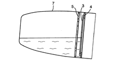
図1は、閉鎖装置2と容器1とを示している。容器1は、流体を保持するための容器本体部分7と、使用者の口に直接に適用するための、取り外し可能な蓋またはリム部分6と、を含んでいる。リム部分は、容器から容易に取り外し可能であり、このため、容器は、容易に満たされ、または/および洗浄される。しかしながら、これらの作業は、リム部分6が所定位置のままでも実行可能である。容器の周囲に延びるプッシュオン(push-on)フランジ(図示せず)が、リム部分6を容器本体部分7に固定するよう使用され得る。または、リム部分6および容器本体部分7が、ねじ式の結合によって互いに取り付けられ得る。
FIG. 1 shows a
閉鎖装置2は、バルブディスクの形状からなる弁板3を含む双安定のバルブと、第1および第2縁部4,5を有する第1および第2バルブシート34,35と、を備えている。弁板3は、第1縁部4と第2縁部5との間で移動可能となっており、また、それらに係合するとき、バルブの閉鎖および開放位置をそれぞれ画定する。容器が直立しているとき、第1縁部4は、第2縁部5の上方に位置している。従って、バルブを開放するため、下方への力、または容器1の内側に向かう力が、弁板3に作用するために必要とされる。また、バルブを閉鎖するため、反対方向における力、すなわち、容器1の内部から遠ざかる力が必要とされる。このようにして、容器1から飲むことが望まれるとき、弁板3をゆるめることによって、バルブが開放される。容器1からひと口飲む場合などに、使用者の鼻または唇によって弁板3がゆるめられるよう弁板3を構成することが可能である。有利には、弁板3は、一体的に移動する部品として構成される。
The
図2は、バルブディスク3を有する図1の閉鎖装置2および容器1であって、開放位置にある場合、すなわち第2縁部5に係合している場合の閉鎖装置2および容器1を示している。弁板3の周縁には、多数の凹部10が形成されている。また図6に示すように、縁部5の内側の周縁には、多数の凹部13が形成されている。縁部5は、図2により明確に示されているように、弁板3が縁部5に着座しているときに流体9が凹部10および凹部13を通ることができるよう、構成されている。符号10は、凹部や後述する孔など、流体9を通すために弁板3に形成された部分を表している。
FIG. 2 shows the
図3は、弁板3を有する図1の閉鎖装置2および容器1であって、閉鎖位置にある場合、すなわち第1縁部4に係合している場合の閉鎖装置2および容器1を示している。第1縁部4の寸法は、弁板3が第1縁部4に係合する場合にバルブディスクの周囲の周りの凹部が閉鎖され、これによって流体が流出しないようになっている。
FIG. 3 shows the
第1および第2縁部4,5は、バルブディスクを所定位置に保持するための少なくとも1つの磁石を含んでいる。好ましくは、縁部4,5は、磁性材料が含浸されたプラスチック材料などの、磁性材料からなっており、また、バルブディスクは、磁石に引きつけられ得る金属材料からなっている。弁板3を閉鎖位置に保持するために、上側の縁部4のみが磁化され、また、バルブが開放されているときに弁板3を下側の縁部5に対して保持するために、重力を当てにすることが可能である。しかし、そのような構成は、本発明の範囲内ではない。バルブディスク3を所定位置に保持するための磁気的手段に代えて、掛け金機構などの機械的手段が利用されてもよい。しかしながら、掛け金機構などの機械的手段は、本発明の範囲内ではない。
The first and
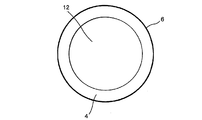
図4は、容器1のリム部分6の内側に収められた第1縁部4を示す平面図である。縁部4が、容器リム部分6に一体的に形成されていてもよく、容器リム部分6から独立して形成され、容器リム部分6に取り付けられていてもよい。縁部4は、中央環状穴12を画定しており、バルブが開放されているとき、流体がこの中央環状穴12を通る。縁部は、ガスケットまたはシールを備えていてもよい。若しくは、縁部が、少なくとも部分的にガスケットまたはシールによって構成されていてもよい。
FIG. 4 is a plan view showing the
図5は、部材3の周囲に均等に分布する凹部10を含む弁板3を示す平面図である。弁板3は、安全バルブなどの圧力開放手段32を含んでいてもよい。
FIG. 5 is a plan view showing the
図6は、容器本体部分7の壁8の内側に収められた第2縁部5を示す平面図である。好ましくは、弁板3は、閉鎖位置にある場合に、開放位置にある場合よりもより堅固に保持される。これによって、装置が閉鎖されているとき、使用者が装置を開放することを決めるまで、装置が閉鎖されたままとなることが確実になり、また、容器からの漏れをなくすのに役立つ。さらに、弁板3を開放位置に保持するのに必要とされる力は、以下のことを確実にするために最適化されている。すなわち、使用者が容器から飲むとき、飲む動作がバルブの閉鎖を引き起こさず、しかし、バルブを開放保持する力が、容器がひっくり返された場合または落とされた場合に弁板3が閉鎖位置に押し込まれる程度に弱いよう、最適化されている。これを磁気的に実現する1つの方法は、第2縁部5を第1縁部4よりも磁気的に弱くすることである。示されている例において、このことは、第2縁部5を、第1縁部4よりも弱い磁性材料から形成することによって実現されている。この場合、とりわけ、第2縁部5において、のこぎり状の歯の構成が用いられている。バルブが開放されているときに流体が通る凹部13が、第2縁部5によって画定されている。弁板3は、装置が開放位置にあり、弁板3が縁部5に着座しているとき、この凹部が閉鎖されないよう構成されている。
FIG. 6 is a plan view showing the
図示はされていないが、縁部のその他の構造は、1つまたは2つ以上の磁気を帯びたバンド(magnetic band)を利用している。磁気を帯びたバンドは、バルブディスクが設けられる容器の内周面に配置されている。バルブディスクが閉鎖装置から落ちるのを防ぐため、磁気を帯びたバンドの下方および/または上方に、フランジが設けられていてもよい。 Although not shown, other structures at the edges utilize one or more magnetic bands. Band magnetized is disposed on the inner peripheral surface of the container valves disk is provided. Since the valve disc is prevented from falling from the closure device, the lower and / or upper band magnetized, but it may also have a flange is provided.
図7は、弁板3が開放位置にあるときの、図1の閉鎖装置2および容器1を示している。この場合、容器が傾けられており、また、使用者が容器から飲んでいる。矢印Aは、流体が容器から流出する経路を示している。はじめに、流体は、第2縁部5の凹部13、および、弁板3の凹部10の間を通る。流体は、その後、流体は、第1縁部4によって画定される穴12を通り、そして、容器リム部分6を超えて使用者の口の中に入る。
FIG. 7 shows the
図8に示されているように、第2縁部5の磁石の強さは、使用者が容器を鉛直に対して所定角度を越えて傾けた場合、容器本体部分7の内側にある流体の量によっては、弁板3が流体圧力によって閉鎖位置に動くよう選択される。同様に、装置が落とされた、またはひっくり返された場合、流体の圧力が、弁板3を閉鎖位置に移動させる。バルブは、使用者が容器を振る場合に閉じるよう構成されていてもよい。装置は、単に弁板3を押すことにより再び開放されてもよい。
As shown in FIG. 8, the magnet strength of the
図9は、弁板3の変形例を示している。ここでは、弁板3の上面上にドーム状の突起部が設けられている。突起部14は、閉鎖装置内に残っている流体が容器の本体部分7に戻るよう導くのを助ける。さらに、突起部14は、使用者が弁板3を押すことを容易にするボタンとして働くことができる。
FIG. 9 shows a modification of the
好ましくは、容器本体部分7の面8は、図7および図8に示すように、上下方向において外方へ凸となるよう湾曲した面の輪郭を有している。この特徴により、容器がひっくり返されたときに生じる流体の流れが弱められ、これによって、バルブが現実に封をする前にバルブを通って漏れる流体の量が減らされる。
Preferably, the
図10は、閉鎖装置の異なる形態を示している。この場合、弁板は、互いに結合された第1および第2モーション制限エレメント22,23を備えている。第1および第2モーション制限エレメント22,23は、バルブリム部24を有するバルブシート25に係合可能となっている。容器が直立しているとき、第1モーション制限エレメント22は、第2モーション制限エレメント23の上に配置される。また、バルブが開放位置にあるとき、第1モーション制限エレメントは、バルブリム部24に係合する。第2モーション制限エレメントは、第1モーション制限エレメントの下に配置されている。また、バルブが閉鎖位置にあるとき、第2モーション制限エレメントは、バルブリム部24に係合する。
FIG. 10 shows a different form of the closure device. In this case, the valve plate comprises first and second
第1モーション制限エレメント22は、その周囲に一連の孔を含んでいる。第1モーション制限エレメント22がバルブリム部24に当接しているとき、これらの孔が、流体を通すことができる。
The first
図10に示す装置は、図1乃至9に示す装置とほぼ同様に作用する。2つの縁部と、好ましくは平坦なバルブディスクの形状を有する弁板と、が設けられる代わりに、ただ1つの縁部と、2つのディスクエレメントを有する弁板とが設けられる点が異なるのみである。2つのディスクエレメントは、スピンドル21により互いに結合され得る。
The apparatus shown in FIG. 10 operates in substantially the same manner as the apparatus shown in FIGS. And two edges, preferably a valve plate having the shape of a flat valve disc, instead of are provided, only one of the edges, are different only in that the valve plate having two disc elements are provided is there. The two disc elements can be connected to each other by means of the
図11は、本発明による閉鎖装置のさらなる形態を示す図である。当該形態は、流体を保持するための容器本体部分7と、容器の上蓋を形成するリム部分6と、を含んでいる。
リム部分6は、容器から容易に取り外し可能となっており、これによって、容器に容易に流体を満たすこと、および/または、容器を洗浄することが可能となっている。しかしながら、これらの作業は、リム部分が元の場所のままで実施されてもよい。
FIG. 11 shows a further form of the closure device according to the invention. The form includes a
The
閉鎖装置2は、弁板3(図11においては図示せず)を有する双安定のバルブと、第1および第2弁座34,35と、を備えている。第1弁座34は、リム部分6から構成されており、また、第2弁座35は、容器本体部分7から構成されている。閉鎖装置はまた、バルブが閉鎖位置にあるときに流体が流出するために通る経路を閉鎖するシールまたはガスケット26を備えている。シール26は、第1バルブ部4における重要な構成要素となっている。装置の動作は、図12乃至17を参照してより詳細に説明される。
The
図12は、開放位置にある図11の閉鎖装置を斜めから見た場合の断面図である。 12 is a cross-sectional view of the closing device of FIG. 11 in the open position when viewed from an oblique direction.
弁板3は、第2弁座35に対して所定の位置に保持されている。弁座35は、容器本体7の外側の周囲に延びる溝の中に少なくとも部分的に配置されたリング28を含んでいる。なお、図示はされていないが、第1弁座34が容器本体7上に配置されていてもよく、また、第2弁座35がリム部分6上に配置されていてもよい。弁座35はまた、閉鎖位置にある場合に弁板3が着座する縁またはフランジ29を備えている。リム29は、少なくとも部分的に、容器1の内側の部分の内側の周囲に形成されている。リム29は、弁板3の移動の最大程度を制限する制限ストップを画定している。
The
弁板3は、磁力によって閉鎖位置に保持されている。リング28は、鋼などの、磁石に引き寄せられる材料から構成され得る。この場合、弁板3は、リング28に向かって磁力を及ぼす材料から構成されている、または、リング28に向かって磁力を及ぼす材料を備えている。または、リング28は、引き寄せの磁力を発生させることができる材料から構成され得る、または、引き寄せの磁力を発生させることができる材料を備えることができる。この場合、弁板3は、代わりに、磁力によって引き寄せられる材料から構成されている、または、引き寄せの磁力を発生させる磁性材料から構成されている。
The
縁部30がリング28と弁板3との間に配置されている場合であっても、リング28と弁板3との間に磁気的な引き寄せが存在している。リング28,30が容器1の外側に配置されていることの利点は、それらが容器1の内側の流体に接触しないということである。
Also edge 30 is a case which is disposed between the
容器がひっくり返された場合、内側の流体が弁板3にぶつかり、そして、部材に及ぶ流体の力が、リング28と弁板3との間の引き寄せの磁力に対して作用する。引き寄せ力の大きさは、使用者がカップから飲む場合に、弁板に及ぶ流体からの力が、引き寄せの磁力に打ち勝つ程度には大きくないよう、しかし、カップがひっくり返された場合に、その力が、引き寄せの力に打ち勝つ程度に大きく、かつ、弁板を弁座35から反対側の弁座34に向かって動かす程度に大きいようになっている。
When the container is turned over, the inner fluid strikes the
図13は、図12に見られるような開放位置にある場合の閉鎖装置を示す斜視図である。流体は、例えば使用者が容器から飲むことを望むときに、容器から流出することができる。なぜなら、弁板3が、弁板3の周囲に位置するとともに、流体がそれを通って流れることができる多数の孔10を備えているからである。弁座35に当接している弁板3の部分は、孔10を含んでいない。このため、流体の流れが妨げられることはない。
13 is a perspective view showing the closure device when in the open position as seen in FIG. The fluid can flow out of the container, for example when the user wishes to drink from the container. This is because the
図14は、閉鎖位置にある装置を示している。弁板3は、リング27と弁板3との間の引き寄せの磁力によって、第1弁座34に対して保持されている。
弁座34は、弁座35に関して上述されたのと同一の特性または特徴を有することができる。縁部またはフランジ29が、閉鎖位置に保持されているときに弁板3が係合するバルブリム6の内側部分によって形成されている。また、容器が直立した状態にあるときに第1弁座が第2弁座の上に配置されている限りは、第1弁座34が容器本体7の中に配置されていてもよい(図示せず)。
FIG. 14 shows the device in the closed position. The
The
閉鎖装置は、第1弁座34の上に配置されたシールまたはガスケット26を備えている。シールは、弁板が閉鎖位置にある場合に、弁板3の孔10がシールによって覆われるよう配置されている。これによって、容器からの流体の経路が閉鎖される。また、シールが部分的にのみ孔を覆っていてもよいということも想像可能である(図示せず)。これによって、閉鎖位置にあるとき、所定のレベルでの流れが、まだ容器から出ることができる。図13と図15との比較は、閉鎖装置が開放位置にあるときに(図13)、弁板3内の孔10が妨げられず、従って、流体が容器1から流出できる、ということを示している。図15においては、シール26が孔を覆っており、従って、流体が容器1から流出できない。
The closure device includes a seal or
図16は、閉鎖装置の断面図の一部を拡大して示す図である。 FIG. 16 is an enlarged view showing a part of a sectional view of the closure device.
弁板3が、開放および閉鎖位置の両方で示されている。ここで、閉鎖位置の場合の部材は点線で示されている。開放位置において、弁板3は、第2縁部30に着座している。弁板とリング28との間の引き寄せの磁力が、弁板を所定位置に保持している。流体は、図に示されている周囲の位置において、孔10を通って流出できる。開放位置において、弁板3は、第1縁部29に着座している。弁板3とリング27との間の引き寄せの磁力が、弁板を開放位置に保持している。シール26が第1弁座34の上に配置されている。このシール26が、弁板3に係合し、これによって、シールが無ければ流体が容器の容器本体部分7の内側から進む経路を遮断する。
The
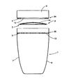
容器1は、スナップ嵌めによる結合部33によって容器本体部分7に固定されたリム部分6によって構成されるよう示されている。リム部分6は、取り外し可能となっている。ここには示されていないが、ねじ結合など、アタッチメントのその他の形態が可能である。
The
図14および図15に示されている閉鎖位置から容器を開放するため、使用者は、容器の上部の孔12を介して弁板3に力を印加することができる。この孔12により、使用者は、弁板3を押すことができる。使用者が、弁板3とリング27との間の引き寄せの磁力に打ち勝つ程度に強く押す場合、弁板3は、使用者によって、弁板3が第2弁座35に対して位置する開放位置に向かって押され得る。使用者が、閉鎖装置を開放するよう押す方向が、図15において矢印により示されている。
To open the container from the closed position shown in FIGS. 14 and 15, the user can apply a force to the
バルブ本体3は、閉鎖位置よりも開放位置にある場合により強固に保持され得る。このことは、内側リム29よりも内側リム28の厚さが小さいことによって達成され得る。
The
図17は、ディスク形態による図11乃至15の弁板3を示している。孔10は、ディスクのメイン領域の内側において、ディスクの外周に均等に配置されている。孔の不規則な配置もまた可能である。弁板3はまた、バルブが開放および閉鎖位置にある場合それぞれにおいて第1および第2縁部4,5に対して隣接するディスクの周囲を囲む隆起したリム31を有している。弁板3は、磁石が含浸されたプラスチック材料からなっていてもよい。圧力開放手段32がディスク上に配置されていてもよい。この部材はまた、弁板の中心から外れて配置されていてもよい(図示せず)。この手段は、安全バルブであってもよい。
FIG. 17 shows the
図18はまた、弁板3を示している。隆起されたリム31と、ディスクの上面にある突起部14とが示されている。突起部はドーム状に形成されている。
FIG. 18 also shows the
バルブが開放または閉鎖でロックされる、閉鎖装置のロック状態を提供することが可能である。これは、閉鎖装置の内側でつまみ(lug)を使用することにより達成され得る。
この場合、例えばバルブ本体を回転させてつまみと係合させることによって、バルブ本体が所定位置にロックされる。
It is possible to provide a locked state of the closing device in which the valve is locked open or closed. This can be achieved by using a lug inside the closure device.
In this case, for example, the valve body is locked at a predetermined position by rotating the valve body and engaging with the knob.
閉鎖装置は、リム部分の内側に完全に配置されていてもよく、この場合、リム部分は、容器本体からの取り外しが可能な、容器の上蓋を形成している。 The closure device may be located completely inside the rim portion, in which case the rim portion forms a top lid of the container that can be removed from the container body.
容器は、少なくとも部分的に、容器の中に温かい流体が入っている場合に膨張する曲がりやすい材料を備えていてもよい。容器本体の側部は、このような膨張を可能とするよう、じゃばら(concertina)のような形態をとっていてもよい。バルブの封止特性が、そのような構成によって劣化することはない。 The container may at least partially comprise a flexible material that expands when a warm fluid is contained in the container. The side of the container body may take the form of a concertina so as to allow such expansion. The sealing properties of the valve are not degraded by such a configuration.
その他に、または、曲がりやすい材料を備えた容器の部分に加えて、容器は、容器の中に温かい流体が封入された場合に容器内の圧力を軽減する手段を備えていてもよい。そのような手段として、広い種類が知られている。手段は、例えば、閉鎖装置または容器に配置された安全バルブを含んでいてもよい。安全バルブは、例えば、シリコンの安全バルブであってもよい。 In addition, or in addition to the portion of the container with a flexible material, the container may be provided with means to relieve the pressure in the container when a warm fluid is enclosed in the container. A wide variety is known as such means. The means may include, for example, a safety valve located on the closure device or container. The safety valve may be, for example, a silicon safety valve.
ここでは図示されてはいないが、請求項によって定義されている保護の範囲内において、各図において開示されている特徴が、他の形態を構成するよう組み合わされてもよい。 Although not shown here, within the scope of protection defined by the claims, the features disclosed in the figures may be combined to form other forms.
ここで、流体という文言は、容器の中に入れられ、かつ容器から注がれる様々な物を含むことを意図しており、例えば、液体および粉末体、または粒状物質を含んでいる。 Here, the term fluid is intended to include various things that can be put into and poured from a container, including, for example, liquids and powders, or particulate matter.
上述のような本発明の形態において、弁板を弁座に対して引き寄せる磁力が、弁板の製造において(磁界を生成する)磁性材料を用いることによって発生され得ることが理解されるであろう。弁座は、磁石により引き寄せられる材料、例えば鋼からなっていてもよい。弁座それ自体が磁性材料からなっていてもよい。この場合、弁板が磁性材料からなっている必要はなく、単に、(鋼などの)磁力によって引き寄せられる材料からなっていればよい。 In the present invention as described above, the magnetic force attracting the valve plate against the valve seat, (which generates a magnetic field) in the manufacture of the valve plate will be understood that may be generated by using a magnetic material . The valve seat may be made of a material attracted by a magnet, for example steel. The valve seat itself may be made of a magnetic material. In this case, the valve plate does not have to be made of a magnetic material, but simply needs to be made of a material attracted by a magnetic force (such as steel).
本発明の使用において、容器は、最初は弁板が閉鎖位置にある場合に、弁板を取り除くことなく、充填または再充填され得ることが理解されるべきである。容器を満たすのに使用される液体(またはその他の注ぐことができる材料、例えば粒状の固体)は、弁板の上部に注がれ得る。これによって、液体の重量が、弁板を閉鎖位置に保持している力に打ち勝ち、そして、バブル部材を開放位置に移動させる。これによって、容器の内側にアクセスすることが可能となる。その後、液体は、容器の中に流れ込むことができる。 In use of the present invention, the container, The first is when the valve plate is in the closed position, without removing the valve plate, it should be understood that can be filled or refilled. The liquid used to fill the container (or other pourable material such as a granular solid) can be poured on top of the valve plate . Thus, the weight of the liquid overcomes the force that holds the valve plate in the closed position, and moves the bubble member to the open position. This allows access to the inside of the container. The liquid can then flow into the container.
Claims (11)
前記閉鎖装置(2)は、双安定バルブを備え、
前記双安定バルブは、弁板(3)と、第1および第2弁座(34,35)と、を有し、
前記双安定バルブは、液体が前記双安定バルブを通って容器から流出することを許容する開放位置であって、前記弁板(3)が前記第2弁座(35)に着座する開放位置、および、液体が前記双安定バルブを通って容器から流出するのを防ぐ閉鎖位置であって、前記弁板(3)が前記第1弁座(34)に着座する閉鎖位置、を有し、
前記弁板(3)は、磁力によって前記開放位置または前記閉鎖位置に保持され、
前記弁板(3)が前記開放位置に保持されているとき、前記弁板(3)を前記開放位置に保持するための磁力よりも大きな力が液体用容器(1)内の液体から前記弁板(3)に加えられると、前記弁板(3)が前記閉鎖位置に移動し、その結果、液体が前記双安定バルブを通って容器から流出することが防がれることを特徴とする閉鎖装置。 In the closure device (2) for the liquid container (1),
The closure device (2) comprises a bistable valve;
The bistable valve has a valve plate (3) and first and second valve seats (34, 35);
The bistable valve is an open position that allows liquid to flow out of the container through the bistable valve, wherein the valve plate (3) is seated on the second valve seat (35); And a closed position for preventing liquid from flowing out of the container through the bistable valve, wherein the valve plate (3) is seated on the first valve seat (34),
The valve plate (3) is held in the open position or the closed position by magnetic force,
When the valve plate (3) is held in the open position, a force larger than the magnetic force for holding the valve plate (3) in the open position is generated from the liquid in the liquid container (1). When added to the plate (3), the valve plate (3) moves to the closed position, so that liquid is prevented from flowing out of the container through the bistable valve. apparatus.
前記第2弁座(35)が、液体を含むことができる容器(1)の本体部分に配置されていることを特徴とする請求項1に記載の閉鎖装置。 The first valve seat (34) is disposed on a removable lid of the container (1);
Said second valve seat (35) is, closure device according to claim 1, characterized in that it is disposed in the body portion of the container (1) that can contain liquid.
前記第2弁座(35)が、前記容器(1)の内側の周囲に少なくとも部分的に形成され、内方に延びる第2縁部(5,30)を備え、
前記開放位置において、前記弁板(3)が前記第2縁部(5,30)に着座し、前記閉鎖位置において、前記弁板(3)が前記第1縁部(4,29)に着座することを特徴とする請求項1または2に記載の閉鎖装置。 The first valve seat (34) includes a first edge (4, 29) formed at least partially around the inside of the container (1) and extending inwardly ;
The second valve seat (35) comprises a second edge (5, 30) formed at least partially around the inside of the container (1) and extending inwardly ;
In the open position, the valve plate (3) is seated on the second edge (5, 30), and in the closed position, the valve plate (3) is seated on the first edge (4, 29). a closure device according to claim 1 or 2, characterized in that.
前記閉鎖装置は、前記弁板(3)が前記閉鎖位置に保持されているときに前記弁板(3)の前記凹部(10)または前記孔(10)を覆うシール(26)を備えたことを特徴とする請求項1乃至3のいずれかに記載の閉鎖装置。 A plurality of recesses (10) are formed in the periphery of the valve plate (3), or a plurality of holes (10) are formed in the valve plate (3),
The closing device includes a seal (26) that covers the recess (10) or the hole (10) of the valve plate (3) when the valve plate (3) is held in the closed position. The closure device according to any one of claims 1 to 3 .
前記手段は、安全バルブであることを特徴とする請求項1乃至9のいずれかに記載の閉鎖装置。 Said device comprises means (32) for relieving the pressure inside said container (1);
It said means closing device according to any one of claims 1 to 9, characterized in that a relief valve.
Applications Claiming Priority (3)
| Application Number | Priority Date | Filing Date | Title |
|---|---|---|---|
| GB0714968.5 | 2007-07-31 | ||
| GB0714968.5A GB2451493B (en) | 2007-07-31 | 2007-07-31 | Closure device for a fluid vessel |
| PCT/GB2008/002610 WO2009016380A1 (en) | 2007-07-31 | 2008-07-31 | Closure device for a fluid vessel |
Related Child Applications (1)
| Application Number | Title | Priority Date | Filing Date |
|---|---|---|---|
| JP2014107213A Division JP2014177309A (en) | 2007-07-31 | 2014-05-23 | Closure device for fluid vessel |
Publications (3)
| Publication Number | Publication Date |
|---|---|
| JP2010535139A JP2010535139A (en) | 2010-11-18 |
| JP2010535139A5 JP2010535139A5 (en) | 2012-09-13 |
| JP5832745B2 true JP5832745B2 (en) | 2015-12-16 |
Family
ID=38529104
Family Applications (2)
| Application Number | Title | Priority Date | Filing Date |
|---|---|---|---|
| JP2010518737A Expired - Fee Related JP5832745B2 (en) | 2007-07-31 | 2008-07-31 | Closure device for fluid containers |
| JP2014107213A Pending JP2014177309A (en) | 2007-07-31 | 2014-05-23 | Closure device for fluid vessel |
Family Applications After (1)
| Application Number | Title | Priority Date | Filing Date |
|---|---|---|---|
| JP2014107213A Pending JP2014177309A (en) | 2007-07-31 | 2014-05-23 | Closure device for fluid vessel |
Country Status (15)
| Country | Link |
|---|---|
| US (2) | US8931654B2 (en) |
| EP (1) | EP2182827B1 (en) |
| JP (2) | JP5832745B2 (en) |
| CN (1) | CN101808552B (en) |
| AU (1) | AU2008281560B2 (en) |
| CA (1) | CA2731441C (en) |
| ES (1) | ES2398763T3 (en) |
| GB (1) | GB2451493B (en) |
| MY (1) | MY152351A (en) |
| NZ (1) | NZ583618A (en) |
| PL (1) | PL2182827T3 (en) |
| PT (1) | PT2182827E (en) |
| RU (1) | RU2472412C2 (en) |
| WO (1) | WO2009016380A1 (en) |
| ZA (1) | ZA201001386B (en) |
Families Citing this family (47)
| Publication number | Priority date | Publication date | Assignee | Title |
|---|---|---|---|---|
| US8317048B2 (en) * | 2008-08-11 | 2012-11-27 | Louis Hajichristou | Self-actuating closure mechanisms for closable articles |
| US8881938B2 (en) | 2012-08-08 | 2014-11-11 | Harl-Bella Holdings, Llc | Lid for beverage container |
| TW201429815A (en) * | 2013-01-31 | 2014-08-01 | Rong-Rong Tian | Beverage container allowing for making both cold beverage and hot beverage |
| USD737142S1 (en) | 2013-08-08 | 2015-08-25 | Harl-Bella Holdings, Llc | Lid with triangular shaped basin |
| USD756773S1 (en) | 2013-08-08 | 2016-05-24 | Harl-Bella Holdings, Llc | Lid with tear line |
| USD736623S1 (en) | 2013-08-08 | 2015-08-18 | Harl-Bella Holdings, Llc | Lid with egg shaped basin |
| USD739729S1 (en) | 2013-08-08 | 2015-09-29 | Harl-Bella Holdings, Llc | Lid for beverage container |
| US20150375913A1 (en) * | 2014-06-30 | 2015-12-31 | Julia A. Brandsdorfer | Drink container adapter |
| USD784072S1 (en) | 2015-01-30 | 2017-04-18 | Magecup Limited | Lid for a beverage container |
| USD804905S1 (en) * | 2015-08-31 | 2017-12-12 | Yeti Coolers, Llc | Container |
| USD808218S1 (en) | 2015-08-31 | 2018-01-23 | Yeti Coolers, Llc | Container |
| USD751338S1 (en) | 2015-11-04 | 2016-03-15 | Yeti Coolers, Llc | Lid |
| US10034580B2 (en) | 2015-10-05 | 2018-07-31 | Yeti Coolers, Llc | Container and handle and method of forming a container and handle |
| US10232993B2 (en) | 2015-10-30 | 2019-03-19 | Yeti Coolers, Llc | Closure and lid and method of forming closure and lid |
| BR112018008820B1 (en) | 2015-10-30 | 2022-09-06 | Yeti Coolers, Llc | CLOSURE AND COVER AND CLOSURE AND COVER FORMATION METHOD |
| US10124942B2 (en) | 2015-10-30 | 2018-11-13 | Yeti Coolers, Llc | Closure and lid and method of forming closure and lid |
| US11001419B2 (en) * | 2015-11-16 | 2021-05-11 | Abbey ABDIYE | Lid for beverage containers |
| AU2016359669A1 (en) | 2015-11-25 | 2018-06-07 | Handi-Craft Company | Spoutless drinking cup |
| USD775495S1 (en) * | 2016-03-01 | 2017-01-03 | Thermos L.L.C. | Bottle |
| USD813605S1 (en) | 2016-05-06 | 2018-03-27 | Yeti Coolers, Llc | Container |
| USD814242S1 (en) | 2016-05-06 | 2018-04-03 | Yeti Coolers, Llc | Container |
| USD812979S1 (en) | 2016-05-06 | 2018-03-20 | Yeti Coolers, Llc | Container |
| USD812984S1 (en) | 2016-05-06 | 2018-03-20 | Yeti Coolers, Llc | Handle |
| USD812989S1 (en) | 2016-05-06 | 2018-03-20 | Yeti Coolers, Llc | Handle |
| USD812985S1 (en) | 2016-05-06 | 2018-03-20 | Yeti Coolers, Llc | Handle |
| USD812432S1 (en) | 2016-05-06 | 2018-03-13 | Yeti Coolers, Llc | Container |
| USD812986S1 (en) | 2016-05-06 | 2018-03-20 | Yeti Coolers, Llc | Handle |
| USD820046S1 (en) | 2016-05-06 | 2018-06-12 | Yeti Coolers, Llc | Container |
| USD812988S1 (en) | 2016-05-06 | 2018-03-20 | Yeti Coolers, Llc | Handle |
| USD812987S1 (en) | 2016-05-06 | 2018-03-20 | Yeti Coolers, Llc | Handle |
| US20170367511A1 (en) * | 2016-06-24 | 2017-12-28 | Richard Dean Neff | Self chilling beverage system |
| USD815893S1 (en) | 2016-10-07 | 2018-04-24 | Yeti Coolers, Llc | Lid |
| USD824212S1 (en) | 2016-10-07 | 2018-07-31 | Yeti Coolers, Llc | Lid |
| US11312546B2 (en) * | 2016-11-08 | 2022-04-26 | AFJ Industries, LLC | Container with automatic lid closure |
| USD820044S1 (en) | 2016-11-15 | 2018-06-12 | Plan D Partners, Inc. | Drinking cup with lid |
| CN107198407B (en) | 2017-07-21 | 2019-03-15 | 京东方科技集团股份有限公司 | Anti-watering cup and its control method |
| CA3090484A1 (en) * | 2018-02-06 | 2019-08-15 | Edgewell Personal Care Brands, Llc | Training cup |
| CN115381263A (en) | 2018-10-23 | 2022-11-25 | 野醍冷却器有限责任公司 | Cap assembly and container assembly |
| USD873617S1 (en) * | 2018-12-03 | 2020-01-28 | b.box for kids developments Pty Ltd. | Drinking cup |
| GB201904882D0 (en) * | 2019-04-05 | 2019-05-22 | Magecup Ltd | Fluid vessel closure device |
| USD914455S1 (en) * | 2019-08-07 | 2021-03-30 | Real Value LLC | Tumbler |
| USD982973S1 (en) | 2019-10-09 | 2023-04-11 | Yeti Coolers, Llc | Tumbler |
| USD964102S1 (en) | 2019-10-09 | 2022-09-20 | Yeti Coolers, Llc | Tumbler |
| USD1011883S1 (en) | 2020-02-12 | 2024-01-23 | Magecup Limited | Lid for a drinking vessel |
| USD977912S1 (en) | 2020-10-01 | 2023-02-14 | Yeti Coolers, Llc | Tumbler |
| USD982982S1 (en) | 2020-10-01 | 2023-04-11 | Yeti Coolers, Llc | Tumbler |
| USD988797S1 (en) * | 2021-01-15 | 2023-06-13 | Brumate Inc. | Beverage container with lid |
Family Cites Families (35)
| Publication number | Priority date | Publication date | Assignee | Title |
|---|---|---|---|---|
| US1254251A (en) * | 1917-05-16 | 1918-01-22 | Rollo Morris Magnus | Drinking-weir. |
| US2675815A (en) * | 1952-10-13 | 1954-04-20 | Wallace S Dale | Antispill child's drinking cup with magnetic closure valve |
| US3360161A (en) * | 1965-10-21 | 1967-12-26 | Marlin B Smith | Splashproof drinking vessel |
| US3730399A (en) * | 1972-02-22 | 1973-05-01 | Nospital Ltd | Non-spill drinking cup top |
| US4130215A (en) * | 1978-02-10 | 1978-12-19 | Corey Joe F | No spill beverage cup |
| US4394928A (en) * | 1980-04-22 | 1983-07-26 | Morris Philip | Splash-proof container and cover |
| EP0296618B1 (en) * | 1987-06-25 | 1990-12-05 | Temtec Fahrzeugtechnik Entwicklungsgesellschaft mbH | Self-closing fuel tank seal |
| US4942976A (en) * | 1988-10-17 | 1990-07-24 | Tapour, Inc. | Container closure with spigot valve |
| IT1247132B (en) * | 1991-03-05 | 1994-12-12 | Guala Spa | CLOSING DEVICE FOR BOTTLES, ESPECIALLY INTENDED FOR BOTTLES FOR PRECIOUS BEVERAGES. |
| GB2264109A (en) * | 1992-01-30 | 1993-08-18 | Joel Matthew Sciamma | Liquid dispenser with magnetically operated valve |
| WO1994014588A1 (en) * | 1992-12-22 | 1994-07-07 | Sdt Technologies, Inc. | Closure for dispensing produce from a container |
| US5249703A (en) * | 1993-03-26 | 1993-10-05 | Morry Karp | Travel mug |
| US5979689A (en) * | 1995-02-16 | 1999-11-09 | Lansky; Daryl J. | Splash/slosh guard for drinking vessels |
| US5540350A (en) * | 1995-02-16 | 1996-07-30 | Mallory Industries Inc. | Splash/slosh guard for drinking vessels |
| RU95106855A (en) * | 1995-04-28 | 1996-12-10 | С.П. Львов | Collapsible container for liquid |
| US5573139A (en) * | 1995-07-05 | 1996-11-12 | Yeh; Frank | Drinking mug with lid and mug body formed from one piece |
| JPH1029657A (en) | 1996-07-16 | 1998-02-03 | Hiroshi Nakahata | Container for humidifying |
| GB9717595D0 (en) * | 1997-08-21 | 1997-10-22 | Metal Box Plc | Valves for packaging containers |
| CN2390508Y (en) * | 1999-09-17 | 2000-08-09 | 吴凤君 | Insulation cup |
| DE60009445T2 (en) * | 2000-02-28 | 2005-03-24 | Guala Closures S.P.A. | Safety closure for bottles for liqueur or the like |
| US6305571B1 (en) * | 2000-06-07 | 2001-10-23 | Donny Chu | Lid device with splashless baffle |
| AU2001266159A1 (en) | 2000-06-23 | 2002-01-02 | Sybre Limited | Spill proof closure and cup |
| US6488173B2 (en) * | 2000-07-06 | 2002-12-03 | Michael Milan | Beverage container lid having baffle arrangement for liquid cooling |
| US6702145B2 (en) * | 2000-09-26 | 2004-03-09 | Alexander R. Malcolm | Splash-proof lid for a cup |
| US6805266B2 (en) * | 2001-06-04 | 2004-10-19 | Av Doron | Safety device for a liquid-containing vessel |
| US6749092B2 (en) * | 2001-08-10 | 2004-06-15 | Seaquist Closures Foreign, Inc. | Deformable dispensing valve |
| US7017768B2 (en) * | 2002-05-21 | 2006-03-28 | Randy Jerome Iskierka | Floatable barrier for use with a beverage container |
| CN2598466Y (en) * | 2002-12-18 | 2004-01-14 | 王琨 | Cup |
| US20040232154A1 (en) * | 2003-05-19 | 2004-11-25 | Fort James Corporation | Splash Resistant Lid With a Snap-On Baffle |
| US7100790B2 (en) * | 2004-04-15 | 2006-09-05 | Dark Richard C G | Spill-resistant metered flow cap for a cup |
| JP4633519B2 (en) * | 2005-03-31 | 2011-02-16 | 明治製菓株式会社 | Midecamycin high producing bacteria |
| US20060226146A1 (en) | 2005-04-06 | 2006-10-12 | Haberman Mandy N | Dispensing vessels |
| EP1898756A2 (en) * | 2005-07-07 | 2008-03-19 | Chef'n Corporation | Apparatus and method for magnetically sealing a beverage container lid |
| JP4666258B2 (en) * | 2006-01-11 | 2011-04-06 | 横河電機株式会社 | Data access system |
| US7513380B2 (en) * | 2006-01-20 | 2009-04-07 | Robert Canedo | Self closing container |
-
2007
- 2007-07-31 GB GB0714968.5A patent/GB2451493B/en not_active Expired - Fee Related
-
2008
- 2008-07-31 CA CA2731441A patent/CA2731441C/en active Active
- 2008-07-31 MY MYPI20100485 patent/MY152351A/en unknown
- 2008-07-31 US US12/452,993 patent/US8931654B2/en not_active Expired - Fee Related
- 2008-07-31 PT PT87882445T patent/PT2182827E/en unknown
- 2008-07-31 JP JP2010518737A patent/JP5832745B2/en not_active Expired - Fee Related
- 2008-07-31 RU RU2010107206/12A patent/RU2472412C2/en not_active IP Right Cessation
- 2008-07-31 WO PCT/GB2008/002610 patent/WO2009016380A1/en active Application Filing
- 2008-07-31 AU AU2008281560A patent/AU2008281560B2/en not_active Ceased
- 2008-07-31 ES ES08788244T patent/ES2398763T3/en active Active
- 2008-07-31 NZ NZ583618A patent/NZ583618A/en not_active IP Right Cessation
- 2008-07-31 PL PL08788244T patent/PL2182827T3/en unknown
- 2008-07-31 EP EP08788244A patent/EP2182827B1/en active Active
- 2008-07-31 CN CN2008801104551A patent/CN101808552B/en active Active
-
2010
- 2010-02-25 ZA ZA2010/01386A patent/ZA201001386B/en unknown
-
2014
- 2014-05-23 JP JP2014107213A patent/JP2014177309A/en active Pending
- 2014-12-10 US US14/565,620 patent/US20150090714A1/en not_active Abandoned
Also Published As
| Publication number | Publication date |
|---|---|
| JP2010535139A (en) | 2010-11-18 |
| ES2398763T8 (en) | 2013-04-22 |
| EP2182827A1 (en) | 2010-05-12 |
| AU2008281560A1 (en) | 2009-02-05 |
| GB2451493B (en) | 2011-12-14 |
| ZA201001386B (en) | 2011-08-31 |
| CA2731441C (en) | 2015-10-20 |
| RU2472412C2 (en) | 2013-01-20 |
| GB2451493A (en) | 2009-02-04 |
| MY152351A (en) | 2014-09-15 |
| AU2008281560B2 (en) | 2014-12-11 |
| US8931654B2 (en) | 2015-01-13 |
| PT2182827E (en) | 2013-02-04 |
| CA2731441A1 (en) | 2009-02-05 |
| RU2010107206A (en) | 2011-09-20 |
| GB0714968D0 (en) | 2007-09-12 |
| CN101808552A (en) | 2010-08-18 |
| US20100206874A1 (en) | 2010-08-19 |
| ES2398763T3 (en) | 2013-03-21 |
| JP2014177309A (en) | 2014-09-25 |
| CN101808552B (en) | 2013-08-14 |
| NZ583618A (en) | 2011-12-22 |
| EP2182827B1 (en) | 2012-11-21 |
| US20150090714A1 (en) | 2015-04-02 |
| WO2009016380A1 (en) | 2009-02-05 |
| PL2182827T3 (en) | 2013-04-30 |
Similar Documents
| Publication | Publication Date | Title |
|---|---|---|
| JP5832745B2 (en) | Closure device for fluid containers | |
| US5607073A (en) | Valve | |
| JP6118332B2 (en) | Closed assembly for drinking cup | |
| AU2002322675B2 (en) | Fluid dispensing valve and method of use | |
| US5893472A (en) | Spout for valve assembly | |
| US7677402B2 (en) | Closing device with integrated rotary closure for feeding bottle and bottle | |
| JP2009505920A (en) | Liquid leakage prevention lid | |
| US7828170B2 (en) | Rim-mounted drinking aid for liquid containers | |
| EP2937293B1 (en) | Check valve and container with check valve | |
| JP4868401B2 (en) | Beverage container | |
| US20160145011A1 (en) | Container Lid Construction and Associated Methods | |
| WO2010085137A2 (en) | A pendulum cap apparatus | |
| US11058248B2 (en) | Beverage brewing apparatus and container including a fragile inner container | |
| US20070068893A1 (en) | Spill proof drinking cap for bottles | |
| CN110621202A (en) | Valve and associated method | |
| EP1998652A1 (en) | Non-spill drink container | |
| GB2354231A (en) | A Container | |
| JP4625391B2 (en) | Meal utensils | |
| CA2060005A1 (en) | Spill-proof lid for beverage cup |
Legal Events
| Date | Code | Title | Description |
|---|---|---|---|
| A521 | Written amendment |
Free format text: JAPANESE INTERMEDIATE CODE: A523 Effective date: 20110801 |
|
| A621 | Written request for application examination |
Free format text: JAPANESE INTERMEDIATE CODE: A621 Effective date: 20110801 |
|
| A521 | Written amendment |
Free format text: JAPANESE INTERMEDIATE CODE: A523 Effective date: 20120719 |
|
| A977 | Report on retrieval |
Free format text: JAPANESE INTERMEDIATE CODE: A971007 Effective date: 20121226 |
|
| A131 | Notification of reasons for refusal |
Free format text: JAPANESE INTERMEDIATE CODE: A131 Effective date: 20130104 |
|
| A601 | Written request for extension of time |
Free format text: JAPANESE INTERMEDIATE CODE: A601 Effective date: 20130404 |
|
| A602 | Written permission of extension of time |
Free format text: JAPANESE INTERMEDIATE CODE: A602 Effective date: 20130411 |
|
| A521 | Written amendment |
Free format text: JAPANESE INTERMEDIATE CODE: A523 Effective date: 20130702 |
|
| A02 | Decision of refusal |
Free format text: JAPANESE INTERMEDIATE CODE: A02 Effective date: 20140124 |
|
| A521 | Written amendment |
Free format text: JAPANESE INTERMEDIATE CODE: A523 Effective date: 20140523 |
|
| A521 | Written amendment |
Free format text: JAPANESE INTERMEDIATE CODE: A821 Effective date: 20140526 |
|
| A911 | Transfer of reconsideration by examiner before appeal (zenchi) |
Free format text: JAPANESE INTERMEDIATE CODE: A911 Effective date: 20140617 |
|
| A912 | Removal of reconsideration by examiner before appeal (zenchi) |
Free format text: JAPANESE INTERMEDIATE CODE: A912 Effective date: 20140815 |
|
| A601 | Written request for extension of time |
Free format text: JAPANESE INTERMEDIATE CODE: A601 Effective date: 20150630 |
|
| A601 | Written request for extension of time |
Free format text: JAPANESE INTERMEDIATE CODE: A601 Effective date: 20150730 |
|
| A521 | Written amendment |
Free format text: JAPANESE INTERMEDIATE CODE: A523 Effective date: 20150828 |
|
| A61 | First payment of annual fees (during grant procedure) |
Free format text: JAPANESE INTERMEDIATE CODE: A61 Effective date: 20151028 |
|
| R150 | Certificate of patent or registration of utility model |
Ref document number: 5832745 Country of ref document: JP Free format text: JAPANESE INTERMEDIATE CODE: R150 |
|
| S111 | Request for change of ownership or part of ownership |
Free format text: JAPANESE INTERMEDIATE CODE: R313113 |
|
| R350 | Written notification of registration of transfer |
Free format text: JAPANESE INTERMEDIATE CODE: R350 |
|
| R250 | Receipt of annual fees |
Free format text: JAPANESE INTERMEDIATE CODE: R250 |
|
| LAPS | Cancellation because of no payment of annual fees |