JP5828079B2 - Lighting device and lighting system - Google Patents
Lighting device and lighting system Download PDFInfo
- Publication number
- JP5828079B2 JP5828079B2 JP2011187129A JP2011187129A JP5828079B2 JP 5828079 B2 JP5828079 B2 JP 5828079B2 JP 2011187129 A JP2011187129 A JP 2011187129A JP 2011187129 A JP2011187129 A JP 2011187129A JP 5828079 B2 JP5828079 B2 JP 5828079B2
- Authority
- JP
- Japan
- Prior art keywords
- unit
- light source
- connection terminal
- lighting device
- external device
- Prior art date
- Legal status (The legal status is an assumption and is not a legal conclusion. Google has not performed a legal analysis and makes no representation as to the accuracy of the status listed.)
- Expired - Fee Related
Links
- 230000005540 biological transmission Effects 0.000 claims description 44
- 239000004020 conductor Substances 0.000 claims description 37
- 238000005286 illumination Methods 0.000 claims description 18
- WABPQHHGFIMREM-UHFFFAOYSA-N lead(0) Chemical compound [Pb] WABPQHHGFIMREM-UHFFFAOYSA-N 0.000 claims description 18
- 230000002093 peripheral effect Effects 0.000 claims description 6
- 238000009795 derivation Methods 0.000 claims 1
- 238000003825 pressing Methods 0.000 description 12
- 239000000463 material Substances 0.000 description 7
- 239000000758 substrate Substances 0.000 description 4
- 238000005452 bending Methods 0.000 description 3
- 210000000078 claw Anatomy 0.000 description 2
- 239000000470 constituent Substances 0.000 description 2
- 239000003365 glass fiber Substances 0.000 description 2
- 238000012423 maintenance Methods 0.000 description 2
- 239000004925 Acrylic resin Substances 0.000 description 1
- 229920000178 Acrylic resin Polymers 0.000 description 1
- NIXOWILDQLNWCW-UHFFFAOYSA-N acrylic acid group Chemical group C(C=C)(=O)O NIXOWILDQLNWCW-UHFFFAOYSA-N 0.000 description 1
- 229920000122 acrylonitrile butadiene styrene Polymers 0.000 description 1
- 239000002390 adhesive tape Substances 0.000 description 1
- 229910052782 aluminium Inorganic materials 0.000 description 1
- XAGFODPZIPBFFR-UHFFFAOYSA-N aluminium Chemical compound [Al] XAGFODPZIPBFFR-UHFFFAOYSA-N 0.000 description 1
- 239000011162 core material Substances 0.000 description 1
- 238000010586 diagram Methods 0.000 description 1
- 230000000694 effects Effects 0.000 description 1
- 239000003822 epoxy resin Substances 0.000 description 1
- 239000004744 fabric Substances 0.000 description 1
- 239000007769 metal material Substances 0.000 description 1
- 238000000034 method Methods 0.000 description 1
- 238000001579 optical reflectometry Methods 0.000 description 1
- 229920003023 plastic Polymers 0.000 description 1
- 229920000647 polyepoxide Polymers 0.000 description 1
- 229920005990 polystyrene resin Polymers 0.000 description 1
- 230000001681 protective effect Effects 0.000 description 1
- 239000003566 sealing material Substances 0.000 description 1
- 230000008054 signal transmission Effects 0.000 description 1
- 230000009466 transformation Effects 0.000 description 1
- 238000003466 welding Methods 0.000 description 1
Images


Classifications
-
- F—MECHANICAL ENGINEERING; LIGHTING; HEATING; WEAPONS; BLASTING
- F21—LIGHTING
- F21V—FUNCTIONAL FEATURES OR DETAILS OF LIGHTING DEVICES OR SYSTEMS THEREOF; STRUCTURAL COMBINATIONS OF LIGHTING DEVICES WITH OTHER ARTICLES, NOT OTHERWISE PROVIDED FOR
- F21V23/00—Arrangement of electric circuit elements in or on lighting devices
- F21V23/003—Arrangement of electric circuit elements in or on lighting devices the elements being electronics drivers or controllers for operating the light source, e.g. for a LED array
- F21V23/004—Arrangement of electric circuit elements in or on lighting devices the elements being electronics drivers or controllers for operating the light source, e.g. for a LED array arranged on a substrate, e.g. a printed circuit board
- F21V23/006—Arrangement of electric circuit elements in or on lighting devices the elements being electronics drivers or controllers for operating the light source, e.g. for a LED array arranged on a substrate, e.g. a printed circuit board the substrate being distinct from the light source holder
-
- F—MECHANICAL ENGINEERING; LIGHTING; HEATING; WEAPONS; BLASTING
- F21—LIGHTING
- F21V—FUNCTIONAL FEATURES OR DETAILS OF LIGHTING DEVICES OR SYSTEMS THEREOF; STRUCTURAL COMBINATIONS OF LIGHTING DEVICES WITH OTHER ARTICLES, NOT OTHERWISE PROVIDED FOR
- F21V21/00—Supporting, suspending, or attaching arrangements for lighting devices; Hand grips
- F21V21/02—Wall, ceiling, or floor bases; Fixing pendants or arms to the bases
-
- F—MECHANICAL ENGINEERING; LIGHTING; HEATING; WEAPONS; BLASTING
- F21—LIGHTING
- F21V—FUNCTIONAL FEATURES OR DETAILS OF LIGHTING DEVICES OR SYSTEMS THEREOF; STRUCTURAL COMBINATIONS OF LIGHTING DEVICES WITH OTHER ARTICLES, NOT OTHERWISE PROVIDED FOR
- F21V23/00—Arrangement of electric circuit elements in or on lighting devices
- F21V23/001—Arrangement of electric circuit elements in or on lighting devices the elements being electrical wires or cables
- F21V23/002—Arrangements of cables or conductors inside a lighting device, e.g. means for guiding along parts of the housing or in a pivoting arm
-
- F—MECHANICAL ENGINEERING; LIGHTING; HEATING; WEAPONS; BLASTING
- F21—LIGHTING
- F21V—FUNCTIONAL FEATURES OR DETAILS OF LIGHTING DEVICES OR SYSTEMS THEREOF; STRUCTURAL COMBINATIONS OF LIGHTING DEVICES WITH OTHER ARTICLES, NOT OTHERWISE PROVIDED FOR
- F21V23/00—Arrangement of electric circuit elements in or on lighting devices
- F21V23/06—Arrangement of electric circuit elements in or on lighting devices the elements being coupling devices, e.g. connectors
-
- F—MECHANICAL ENGINEERING; LIGHTING; HEATING; WEAPONS; BLASTING
- F21—LIGHTING
- F21V—FUNCTIONAL FEATURES OR DETAILS OF LIGHTING DEVICES OR SYSTEMS THEREOF; STRUCTURAL COMBINATIONS OF LIGHTING DEVICES WITH OTHER ARTICLES, NOT OTHERWISE PROVIDED FOR
- F21V27/00—Cable-stowing arrangements structurally associated with lighting devices, e.g. reels
-
- F—MECHANICAL ENGINEERING; LIGHTING; HEATING; WEAPONS; BLASTING
- F21—LIGHTING
- F21S—NON-PORTABLE LIGHTING DEVICES; SYSTEMS THEREOF; VEHICLE LIGHTING DEVICES SPECIALLY ADAPTED FOR VEHICLE EXTERIORS
- F21S2/00—Systems of lighting devices, not provided for in main groups F21S4/00 - F21S10/00 or F21S19/00, e.g. of modular construction
- F21S2/005—Systems of lighting devices, not provided for in main groups F21S4/00 - F21S10/00 or F21S19/00, e.g. of modular construction of modular construction
-
- F—MECHANICAL ENGINEERING; LIGHTING; HEATING; WEAPONS; BLASTING
- F21—LIGHTING
- F21V—FUNCTIONAL FEATURES OR DETAILS OF LIGHTING DEVICES OR SYSTEMS THEREOF; STRUCTURAL COMBINATIONS OF LIGHTING DEVICES WITH OTHER ARTICLES, NOT OTHERWISE PROVIDED FOR
- F21V21/00—Supporting, suspending, or attaching arrangements for lighting devices; Hand grips
- F21V21/02—Wall, ceiling, or floor bases; Fixing pendants or arms to the bases
- F21V21/03—Ceiling bases, e.g. ceiling roses
-
- F—MECHANICAL ENGINEERING; LIGHTING; HEATING; WEAPONS; BLASTING
- F21—LIGHTING
- F21Y—INDEXING SCHEME ASSOCIATED WITH SUBCLASSES F21K, F21L, F21S and F21V, RELATING TO THE FORM OR THE KIND OF THE LIGHT SOURCES OR OF THE COLOUR OF THE LIGHT EMITTED
- F21Y2105/00—Planar light sources
-
- F—MECHANICAL ENGINEERING; LIGHTING; HEATING; WEAPONS; BLASTING
- F21—LIGHTING
- F21Y—INDEXING SCHEME ASSOCIATED WITH SUBCLASSES F21K, F21L, F21S and F21V, RELATING TO THE FORM OR THE KIND OF THE LIGHT SOURCES OR OF THE COLOUR OF THE LIGHT EMITTED
- F21Y2115/00—Light-generating elements of semiconductor light sources
- F21Y2115/10—Light-emitting diodes [LED]
- F21Y2115/15—Organic light-emitting diodes [OLED]
Landscapes
- Engineering & Computer Science (AREA)
- General Engineering & Computer Science (AREA)
- Microelectronics & Electronic Packaging (AREA)
- Arrangement Of Elements, Cooling, Sealing, Or The Like Of Lighting Devices (AREA)
- Non-Portable Lighting Devices Or Systems Thereof (AREA)
- Fastening Of Light Sources Or Lamp Holders (AREA)
- Circuit Arrangement For Electric Light Sources In General (AREA)
Description
本発明は、光源に発光パネルを用いた照明装置及びそれを用いた照明システムに関する。 The present invention relates to an illumination device using a light-emitting panel as a light source and an illumination system using the illumination device.
従来から、複数のタイル状のフラットパネル発光ユニット(以下、発光ユニットという)を備えた照明システムが知られている。この照明システムにおいて、発光ユニットは、グリッド状に互いに隣接するように配置されている。そして、隣り合う発光ユニットは、発光ユニットの隣り合う縁部に設けられた接点を介して互いに電気的に接続されており、この接点を介して1つの発光ユニットから次の発光ユニットへと電力伝送が行われる(例えば、特許文献1参照)。 DESCRIPTION OF RELATED ART Conventionally, the illumination system provided with the several tile-shaped flat panel light emission unit (henceforth a light emission unit) is known. In this illumination system, the light emitting units are arranged adjacent to each other in a grid shape. Adjacent light emitting units are electrically connected to each other via contacts provided at adjacent edges of the light emitting units, and power is transmitted from one light emitting unit to the next light emitting unit via these contacts. (For example, refer to Patent Document 1).
この種の発光ユニットにおいては、隣り合う発光ユニットを電気的に接続するために、導線等の外部導体が用いられ、この外部導体の両端が、各発光ユニットの接点にそれぞれ接続される。このとき、施工性の観点から、外部導体を曲げたり、又は形状が異なる外部導体を用いることにより、各発光ユニットが電気的に接続される。 In this type of light emitting unit, an external conductor such as a conducting wire is used to electrically connect adjacent light emitting units, and both ends of the external conductor are connected to the contacts of each light emitting unit. At this time, from the viewpoint of workability, each light emitting unit is electrically connected by bending the outer conductor or using an outer conductor having a different shape.
しかしながら、上記発光ユニットが互いに隣接するように配置されていると、隣り合うユニット同士を電気的に接続するための接点が近接するので、これら接点を接続する外部導体を収容するスペースが制約される。その結果、発光ユニットの配置に応じて、例えば、外部導体を曲げたり、又は形状が異なる外部導体を用いようとしても、スペースが足りず、施工性が悪くなることがある。ところが、このスペースを確保しようとすると、発光ユニットの配置が制限されてしまい、例えば、発光ユニットを隙間なく配置することができず、発光ユニットの配置自由度が低下してしまう。 However, when the light emitting units are arranged so as to be adjacent to each other, since the contacts for electrically connecting the adjacent units are close to each other, the space for accommodating the external conductors connecting these contacts is limited. . As a result, depending on the arrangement of the light emitting units, for example, even if the outer conductor is bent or an outer conductor having a different shape is used, there is a shortage of space and workability may be deteriorated. However, if this space is to be secured, the arrangement of the light emitting units is limited. For example, the light emitting units cannot be arranged without a gap, and the degree of freedom in arranging the light emitting units is reduced.
本発明は、上記課題を解決するためになされたものであり、外部装置と電気的に接続するときの施工性を向上でき、その接続に伴って生じる配置の制約を減らして配置自由度を向上できる照明装置及びそれを用いた照明システムを提供することを目的とする。 The present invention has been made to solve the above-mentioned problems, and can improve the workability when electrically connecting to an external device, reducing the restrictions on the arrangement caused by the connection and improving the degree of freedom of arrangement. An object of the present invention is to provide a lighting device that can be used and a lighting system using the same.
上記課題を解決するため、本発明の照明装置は、発光パネルを有する光源部と、前記光源部の非発光面側に取り付けられる装着部と、を備え、前記装着部は、前記発光パネルを点灯制御する回路基板を有する照明装置であって、前記装着部は、前記回路基板と外部装置とを電気的に繋ぐための外部導体が接続される接続端子を有し、前記接続端子は、前記装着部の前記光源部が取り付けられる面の外周端部よりも内方寄りに配置されており、前記接続端子に前記外部導体が接続され、かつ前記光源部に前記装着部が取り付けられた状態で、該光源部と該装着部との間には、該外部導体を通すための隙間が形成されていることを特徴とする。 In order to solve the above problems, an illumination device according to the present invention includes a light source unit having a light emitting panel and a mounting unit attached to a non-light emitting surface side of the light source unit, and the mounting unit lights the light emitting panel. An illumination device having a circuit board to be controlled, wherein the mounting portion includes a connection terminal to which an external conductor for electrically connecting the circuit board and an external device is connected, and the connection terminal is the mounting In the state where the outer conductor is attached to the inner side of the outer peripheral end of the surface to which the light source part is attached, the external conductor is connected to the connection terminal, and the mounting part is attached to the light source part, A gap for passing the outer conductor is formed between the light source part and the mounting part.
前記照明装置において、前記接続端子と前記外部導体とは、それぞれに設けられたコネクタを用いて接続され、前記接続端子のコネクタは、前記装着部の外方を向くように配置されていることが好ましい。 In the lighting device, the connection terminal and the external conductor are connected to each other using a connector provided on each of the connection terminals, and the connector of the connection terminal is arranged to face outward of the mounting portion. preferable.
前記照明装置において、前記接続端子のコネクタは、前記外部装置と対向するように配置されていることが好ましい。 In the lighting device, it is preferable that the connector of the connection terminal is disposed so as to face the external device.
前記照明装置において、前記接続端子は、前記外部装置から電力供給を受けるための受電部と、前記受電部により受けた電力を、前記とは別の外部装置に供給するための送電部と、を有していてもよい。 In the lighting device, the connection terminal includes a power receiving unit for receiving power supply from the external device, and a power transmission unit for supplying the power received by the power receiving unit to another external device. You may have.
前記照明装置において、前記接続端子は、前記外部装置から制御信号を受信するための受信部と、前記受信部により受信された制御信号又は該制御信号を基に生成された信号を、前記とは別の外部装置に送信するための送信部と、を有していてもよい。 In the lighting device, the connection terminal includes a receiving unit for receiving a control signal from the external device, a control signal received by the receiving unit, or a signal generated based on the control signal, And a transmission unit for transmitting to another external device.
前記照明装置において、前記接続端子は、前記外部装置から電力供給を受けるための受電部と、その外部装置から制御信号を受信するための受信部と、前記受電部により受けた電力を、前記とは別の外部装置に供給するための送電部と、前記受信部により受信された制御信号又は該制御信号を基に生成された信号を、その外部装置に送信するための送信部と、を有し、前記受電部及び受信部は、互いに隣り合うように配置されており、前記送電部及び送信部は、互いに隣り合うように配置されていることが好ましい。 In the lighting device, the connection terminal includes a power receiving unit for receiving power supply from the external device, a receiving unit for receiving a control signal from the external device, and the power received by the power receiving unit. Has a power transmission unit for supplying to another external device, and a transmission unit for transmitting the control signal received by the reception unit or a signal generated based on the control signal to the external device. Preferably, the power reception unit and the reception unit are disposed adjacent to each other, and the power transmission unit and the transmission unit are disposed adjacent to each other.
前記照明装置において、前記外部導体を構成する可撓性を有した導線をガイドして、該導線の装置外部への導出方向を調整するための導線配線調整部をさらに備えることが好ましい。 In the lighting device, it is preferable that the lighting device further includes a lead wire adjustment unit for guiding a flexible lead wire constituting the outer conductor and adjusting a lead-out direction of the lead wire to the outside of the device.
前記照明装置において、前記外部導体を構成する可撓性を有した導線をガイドして、該導線の装置外部への導出方向を調整するための導線配線調整部をさらに備え、前記導線配線調整部は、前記接続端子のコネクタが向いている第1の方向に前記導線を導出するための第1のガイドと、前記第1の方向と直交し、かつ前記装着部における前記光源部への取付け面と平行する第2の方向に前記導線を導出するための第2のガイドと、前記第2の方向とは反対である第3の方向に前記導線を導出するための第3のガイドと、を有することが好ましい。 The lighting device further includes a lead wire adjustment unit for guiding a flexible lead wire constituting the outer conductor and adjusting a lead-out direction of the lead wire to the outside of the device, the lead wire adjustment unit Are a first guide for leading out the conducting wire in a first direction in which the connector of the connection terminal is facing, an attachment surface to the light source portion in the mounting portion, which is orthogonal to the first direction A second guide for deriving the conducting wire in a second direction parallel to the second direction, and a third guide for deriving the conducting wire in a third direction opposite to the second direction. It is preferable to have.
前記照明装置は、照明システムに用いられることが好ましい。 The lighting device is preferably used in a lighting system.
本発明によれば、外部導体が接続される接続端子が、装着部の外周端部よりも内方寄りに配置され、光源部と装着部との間には、外部導体を通すための隙間が形成されているので、外部導体を収容するスペースが確保される。従って、外部導体を用いて外部装置と電気的に接続するときに、配置に応じて、例えば、外部導体を曲げたり、又は形状が異なる外部導体を用いることにより余分のスペースが必要になる場合であっても、そのスペースを確保でき、施工性を向上できる。また、外部導体を収容するスペースを確保するための配置制限をなくすことができ、外部装置との電気的な接続に伴って生じる配置の制約を減らすことができ、配置自由度の向上を図ることができる。 According to the present invention, the connection terminal to which the external conductor is connected is disposed inward from the outer peripheral end of the mounting portion, and there is a gap for passing the external conductor between the light source unit and the mounting portion. Since it is formed, a space for accommodating the outer conductor is secured. Therefore, when an external conductor is used for electrical connection to an external device, extra space is required, for example, by bending the external conductor or using an external conductor with a different shape, depending on the arrangement. Even if it exists, the space can be secured and workability can be improved. In addition, it is possible to eliminate arrangement restrictions for securing a space for accommodating external conductors, reduce arrangement restrictions caused by electrical connection with external devices, and improve the degree of arrangement freedom. Can do.
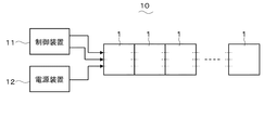
本発明の一実施形態に係る照明装置及びそれを用いた照明システムについて図面を参照して説明する。図1は、本実施形態の照明装置を複数用いた照明システムの構成を示す。本実施形態の照明装置1は、他の照明装置1と電気的に連結可能に構成されており、図示の照明システム10において、照明装置1は、列状に並べて配置され、互いに隣り合う照明装置1と電気的に並列接続されている。照明システム10は、制御装置11と、電源装置12とをさらに備え、制御装置11及び電源装置12は、照明装置1のうち、一端に配置されたものに電気的に接続されている。
An illumination device according to an embodiment of the present invention and an illumination system using the illumination device will be described with reference to the drawings. FIG. 1 shows a configuration of an illumination system using a plurality of illumination devices of the present embodiment. The lighting device 1 of the present embodiment is configured to be electrically connectable to other lighting devices 1. In the illustrated
制御装置11は、接続対象の照明装置1に、照明装置1を制御するための制御信号を2系統で送信する。送信系統は、2系統に限定されず、1系統又は3系統以上であってもよい。電源装置12は、接続対象の照明装置1に、照明装置1を駆動するための電力を供給する。照明装置1は、受信した制御信号又はそれを基に生成した信号と、供給された電力とを、隣の照明装置1に送り、このようにして、信号と電力とは順に伝送される。
The
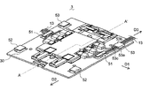
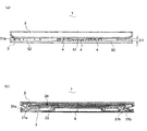
図2は、照明装置1の構成を示す。照明装置1は、光源部2と、光源部2の非発光面側に取り付けられる装着部3とを備える。装着部3は、天井や壁等の装着対象に、ネジ又はとボルト等の固定具を用いて固定され、そのように固定された状態で光源部2が取り付けられることにより、光源部2を装着対象に保持するものである。
FIG. 2 shows the configuration of the lighting device 1. The lighting device 1 includes a
光源部2は、有機EL素子により構成される平板状の発光パネルを収容したパッケージ20を有する。装着部3は、パッケージ20に着脱自在に取り付けられるハウジング30を有し、ハウジング30は、上記発光パネルを点灯制御するための回路基板を収容している。
The
装着部3は、上記回路基板と外部装置とを電気的に繋ぐための可撓性を有した導線13(外部導体)が接続される接続端子4を有する。接続端子4は、装着部3の光源部2が取り付けられる取付け面3aの外周端部よりも内方寄りに配置され、上記回路基板と電気的に接続されている。接続端子4に導線13が接続され、かつ光源部2に装着部3が取り付けられた状態で、光源部2と装着部3との間には、導線13を通すための隙間が形成される。上記外部装置には、制御装置11、電源装置12又は他の照明装置1が含まれる。
The
また、装着部3は、導線13をガイドして、導線13の照明装置1外部への導出方向を調整するための導線配線調整部5を有する。導線配線調整部5は、ハウジング30と一体的に形成されている。
Further, the
パッケージ20及びハウジング30は、いずれも平面視で矩形であり、一方の辺が他方の辺よりも若干大きい長方形状に形成されている。パッケージ20の非発光面側の面を形成する4辺のうち、1辺に沿う端部に保持部21aが設けられている。そして、ハウジング30のパッケージ20が取り付けられる取付け面30aには、保持部21aに保持される被保持部31aが設けられている。取付け面30aは、装着部3の取付け面3aに含まれる。保持部21aは、先端が外側を向いたフック形状に形成され、被保持部31aは、保持部21aの先端を引っ掛けることが可能な形状に形成されている。
Each of the
また、パッケージ20の上記4辺のうち、保持部21aが沿う1辺と対峙する辺に沿う端部には、1対の係合部(同図では不図示)が設けられている。そして、ハウジング30の取付け面30aには、それらの係合部をそれぞれ係合するための1対の被係合部31bが設けられている。上記係合部は、保持部21aと同様に先端が外側を向いたフック形状に形成され、被係合部31bは、上記係合部の先端を引っ掛けることが可能な形状に形成されている。1対の被係合部31bは、互いに連結され、ハウジング30に摺動可能に取り付けられると共に、バネ等の付勢機構32により、装着部3の内方に付勢されている。
Further, a pair of engaging portions (not shown in the figure) is provided at an end portion along a side facing the one side along which the holding
ハウジング30は、取付け面30aの略中央に突設された中空の回路基板収容部33と、光源部2と上記回路基板とを電気的に接続するメス型端子から成る端子受部34が埋設される貫通溝34aとを有する。回路基板収容部33は、上記回路基板を収容している。光源部2が装着部3に取り付けられるとき、貫通溝34aには、光源部2の非発光面側から突出したオス型端子から成る端子部が差し込まれ、その端子部と端子受部34とが接続され、上記回路基板と光源部2とが互いに電気的に接続される。
The
ここで、説明の便宜上、ハウジング30の取付け面30aを形成する4辺のうち、互いに対向する2辺をそれぞれ、第1辺30b、第2辺30cといい、これら2辺と直交し互いに対向する2辺をそれぞれ、第3辺30d、第4辺30eという。被保持部31aは、第1辺30bに沿う端部に配置され、被係合部31bは、第2辺30cに沿う端部に配置されている。
Here, for convenience of explanation, of the four sides forming the mounting
接続端子4は、回路基板収容部33の両側方に設けられており、具体的には、第3辺30d側の側方と、第4辺30e側の側方とに設けられている。接続端子4と導線13とには、それぞれ、コネクタ4a、13aが設けられており、接続端子4と導線13とは、コネクタ4a、13aを用いて接続される。コネクタ4a、13aは、それぞれ、差込型のピン端子を有し、コネクタ4aのピン端子がメス型であって、コネクタ13aのピン端子がオス型であり、それらのピン端子は、互いに抜き差し可能な構成を有する。各ビン端子は、メス型とオス型とが逆であってもよい。コネクタ4aは、その接続面が装着部3の外方を向くように配置されている。回路基板収容部33の取付け面3aからの突出寸法は、コネクタ13aの縦方向の寸法よりも高い。光源部2を装着部3に取り付けた状態での両者間の隙間は、少なくともコネクタ13aを収容する空間を形成する。
The
また、接続端子4は、制御装置11(図1参照)又は他の照明装置1から制御信号を受信するための受信部41と、受信部41により受信された制御信号又はその制御信号を基に生成された信号を、上記とは別の照明装置1に送信するための送信部42とを有する。また、接続端子4は、電源装置12(図1参照)又は他の照明装置1から電力供給を受けるための受電部43と、受電部43により受けた電力を、送信部42による送信対象と同じ照明装置1に供給するための送電部44とを有する。
In addition, the
受信部41と送信部42とは、制御装置11の送信系統数に応じて設けられており、本実施形態では、その送信系統が2系統であることから、受信部41と送信部42とは、2個ずつ設けられている。
The receiving unit 41 and the transmitting
受信部41及び受電部43は、列状で互いに隣り合うように配置され、かつコネクタ4aのコネクタ13aとの接続面が第4辺30eと直交する方向を向くように配置されている。このようにして、制御信号の送信元又は電力供給元である他の照明装置1が第4辺30eに隣接するように配置された状態で、受信部41及び受電部43は、その照明装置1と対向するように配置されている。
The receiving unit 41 and the
送信部42及び送電部44は、列状で互いに隣り合うように配置され、かつコネクタ4aのコネクタ13aとの接続面が第3辺30dと直交する方向を向くように配置されている。このようにして、制御信号の送信先又は電力供給先である他の照明装置1が第3辺d0eに隣接するように配置された状態で、送信部42及び送電部44は、その照明装置1と対向するように配置されている。受信部41及び受電部43の組合せと、送信部42及び送電部44の組合せとは、互いに反対の方向を向いている。
The
導線配線調整部5は、第1ガイド51、第2ガイド52及び第3ガイド53を有する。第1ガイド51は、コネクタ4aが向いている第1方向D1に導線13を導出するためのガイドである。第2ガイド52は、第1方向D1と直交し、かつ取付け面3aと平行する第2方向D2に導線13を導出するためのガイドである。第3ガイド53は、第2方向D2とは反対である第3方向D3に導線13を導出するためのガイドである。
The conductor
第1ガイド51、第2ガイド52及び第3ガイド53は、それらを1組として、受信部41及び受電部43に接続される導線13用として、第4辺30eに沿って1組、設けられている。また、第1ガイド51、第2ガイド52及び第3ガイド53の組合せは、送信部42及び送電部44に接続される導線13用として、第3辺30dに沿って、1組設けられている。それらの組は、互いに同じような構成を有する。
The
ここでは、これら2組のうち、第3辺30dに沿って設けられた組に基づいて説明する。第1ガイド51は、第3辺30dに沿う端部のうち、送信部42及び送電部44の列の略中央に対向する部位に配置されている。第1ガイド51は、ハウジング30の取付け面30aに立設され第1方向D1に沿って延びた支持部51aと、支持部51aの頂部に連なり、その頂部から両側方に延びた導線押付け部51bとを有する。このようにして、第1ガイド51は、第1方向D1に直交する断面が略T字に形成されている。また、第1ガイド51は、導線押付け部51bの先端部に形成されたストッパ51cを有する。ストッパ51cは、導線押付け部51bの下方に収められた導線13が、その下方の空間から抜け出ないように、導線13の動きを規制するためのものである。ストッパ51cは、導線押付け部51bの先端部の取付け面30a側に突設され、第1方向D1に沿って延びている。
Here, it demonstrates based on the group provided along the 3rd edge |
第2ガイド52は、第3辺30dに沿う端部のうち、第2方向D2の端部に設けられている。第2ガイド52は、ハウジング30の取付け面30aに立設され第2方向D2に沿って延びた支持部52aと、支持部52aの頂部に連なり、その頂部からハウジング30の内方に延びた導線押付け部52bとを有する。このようにして、第5ガイド52は、第2方向D2に直交する断面が、略L字を右回りに180度回転させた形状に形成されている。また、第2ガイド52は、導線押付け部52bの先端部に形成されたストッパ52cを有する。ストッパ52cは、導線押付け部52bの下方に収められた導線13が、その下方の空間から抜け出ないように、導線13の動きを規制するためのものである。ストッパ52cは、導線押付け部52bの先端部の取付け面30a側に突設され、第2方向D2に沿って延びている。
The
第3ガイド53は、第3辺30dに沿う端部のうち、第3方向D3の端部に設けられている。第3ガイド53は、第3方向D3に沿って延びており、その形状は第2ガイド52と同等である。
The
照明装置1は、その使用時において、装着部3が装着対象に装着され、その後、接続端子4に導線13が接続されて、光源部2が装着部3に取り付けられる。装着部3の装着対象への装着と、導線13の接続とは、順序が逆であってもよい。
When the lighting device 1 is used, the mounting
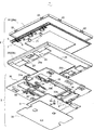
図3は、光源部2及び装着部3の内部構成を示す。光源部2は、パッケージ20と、上述した発光パネル6とに加え、発光パネル6の非発光面側(図中上方向)に設置されてパッケージ20に収容される配線基板7を有する。
FIG. 3 shows the internal configuration of the
発光パネル6と配線基板7とは、耐熱性、耐湿性及び応力緩和性に優れた芯材入りのアクリル系両面接着テープ等により接着固定されており、超音波溶着等により設けられた導電性ワイヤ8により互いに電気的に接続されている。
The light-emitting panel 6 and the
発光パネル6は、透光性を有する四角形の基板上に、透明導電膜から成る正電極、発光機能を有する発光層、光反射性を有する負電極を、順に積層した発光部(不図示)が形成され、その発光部の外側が封止材で被覆されたものである。 The light-emitting panel 6 includes a light-emitting unit (not shown) in which a positive electrode made of a transparent conductive film, a light-emitting layer having a light-emitting function, and a negative electrode having light reflectivity are sequentially stacked on a light-transmitting rectangular substrate. It is formed and the outside of the light emitting part is covered with a sealing material.
配線基板7は、その中央が開口した枠形状に形成されており、その装着部3側の面に、装着部3の端子受部34(図1参照)に差し込まれる上述した端子部71が突設されている。端子部71は、配線基板7と装着部3とを電気的に接続するためのものである。配線基板7は、ガラス繊維布にエポキシ樹脂等を含侵させて硬化させたガラス繊維板、例えば、FR−4等の、難燃性及び低導電率を両立した基材により構成される。
The
パッケージ20は、発光パネル6の発光面側(図中上方向)を覆うカバー20aと、非発光面側を覆うケース20bとにより構成される。カバー20a及びケース20bは、互いに嵌合係止される。
The
カバー20aは、四角形で透明な平板状部材で構成される。カバー20aは、発光パネル6と対向する面が開口した枠状部材、又は少なくとも発光パネル6と対向する面が透明な平板状部材であってもよい。カバー20aがそれらのうちの前者である場合、開口した箇所に透明な保護カバー等が配置されることが好ましい。カバー20aの周縁側部には、カバー20aとケース20bとを係合するための複数の嵌合爪22が突設されている。
The
ケース20bは、カバー20aと対向する面が開口した箱状部材である。ケース20bの開口は、カバー20aに対応した形状であり、その開口にカバー20aが嵌め込まれる。その嵌込みにより、嵌合爪22はケース20bの内側壁に設けられた嵌合溝(不図示)に嵌合され、カバー20aとケース20bとは互いに結合される。ケース20bには、端子部71を装着部3側に露出させるための溝23が形成されており、溝23に端子部71が挿通される。ケース20bの底面は、配線基板7に対応する形状に形成されており、具体的には、外底面における配線基板7の中央開口に対応する部位に凹部24が形成され、その部位が僅かに底上げされている。
The
カバー20a及びケース20bの形状は、照明装置1の用途に応じた任意の形状が用いられ、発光パネル6に対応した形状に形成されているが、本実施形態では、正面視が矩形状であるものとする。カバー20aの構成材料としては、例えば、ABS樹脂、アクリル樹脂、又はポリスチレン樹脂等の透明なプラスチック材料が用いられる。パッケージ20aの構成材料としては、上記カバー20aと同様の材料が用いられる他、例えば、表面に絶縁処理が施されたアルミニウム等の金属材料等の不透明の材料が用いられてもよい。
Arbitrary shapes according to the use of the lighting device 1 are used as the shapes of the
装着部3は、ハウジング30、及び上述した回路基板9に加え、ハウジング30の回路基板収容部33に回路基板9を収容した状態で回路基板9の光源部2とは反対側の面を覆うための絶縁板35を有する。絶縁板35は、外部から物理的にも電気的にも影響を受けないように回路基板9を保護するものである。
The mounting
回路基板9は、配線基板7と同様の基材により構成されており、光源部2側の面に、接続端子4と、発光パネル6を駆動するための駆動ドライバ等の各種素子とが実装されている。上記各種素子は、回路基板9の中央付近に配置され、接続端子4は、回路基板9の端部に配置されている。回路基板9は、光源部2とは反対側から回路基板収容部33に収容される。
The
ハウジング30は、接続端子4に対応する位置に切欠き部36を有する。回路基板9がハウジング30に取り付けられるとき、切欠き部36は、光源部2側に接続端子4を露出させ、回路基板収容部33は、上記各種素子を収容する。回路基板収容部33の周縁には、保持枠33aが設けられ、保持枠33aの内壁には、回路基板9をネジ止めするためのネジ止め部33bが設けられている。保持枠33aは、ネジ止め部33bと共に、回路基板9上に実装された各種素子が、回路基板収容部33の底面に接触しないように、回路基板9を中浮き状態で保持する。回路基板9には、ネジ止め部33bと対応する位置に、ネジ孔91が形成されている。ネジ孔91及びネジ止め部33bにネジ14が挿通されることにより、回路基板9はハウジング30に取り付けられる。回路基板収容部33は、光源部2に装着部3が装着された状態で、頂部がケース20bの凹部24に嵌まる位置に配置されている。
The
また、ハウジング30は、光源部2とは反対側の面に凹設された絶縁板収容部37を有する。絶縁板収容部37は、絶縁板35が嵌め込まれるものであって、絶縁板35に対応する形状であり、厚みが絶縁板35と略同じ寸法である。回路基板収容部33は、この絶縁板収容部37からさらに一段、凹むように形成されている。回路基板9をハウジング30に取り付けた状態で、回路基板9の実装面とは反対側の面が、絶縁板収容部37の底面と略同一の平面になるように、保持枠33aは寸法が予め調整されている。この調整により、絶縁板収容部37に絶縁板35を嵌め込んだ状態で、ハウジング30の底面と絶縁板35の底面との間には段差が殆んどなくなる。そのため、ハウジング30を、その底面が装着対象に接するように取り付けた場合、ハウジング30のがたつきがなくなり、取付けが安定したものになる。
The
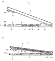
図4は、接続端子4に導線13が接続された状態での導線13の配線例を示す。本配線例においては、導線13が、第1ガイド51によりガイドされており、この配線は、例えば、外部装置が第1方向D1に配置されたときになされる。導線13は、適宜曲げられて、導線押付け部51bの下方空間に集め入れられている。また、導線13は、曲げられた状態からの復元力に起因して、上記の下方空間から抜け出すことがないように、ストッパ51cにより、復元の動きが規制されている。このようにして、導線13は、第1方向D1に導出されるように保持されている。
FIG. 4 shows a wiring example of the
図5は、上記とは別の配線例を示す。この配線例においては、送信部42及び送電部44側の導線13が第3ガイド53によりガイドされており、この配線は、例えば、電力及び信号の送信先である外部装置が第3方向D3に配置されたときになされる。導線13は、第1方向D1から第3方向D3に向けて、略直角に曲げられており、導線押付け部53bの下方空間に集め入れられている。また、導線13は、支持部53aにより、曲げられた状態からの復元が規制されている。また、導線13は、曲げ時に撓んで、上記の下方空間からハウジング30の内方に抜け出すことがないように、ストッパ53cにより移動が制限されている。このようにして、導線13は、第3方向D3に導出されるように保持されている。なお、不図示であるが、第2ガイド52を用いた導線13の配線調整も、第3ガイド53を用いた調整と同様に行うことができる。
FIG. 5 shows another wiring example different from the above. In this wiring example, the
図6及び図7は、光源部2を装着部3に取り付ける手順を示す。装着部3は、予め天井や壁等の装着対象に固定され、導線13(図示せず)が接続端子4に接続されているものとする。図6(a)(b)に示すように、光源部2は、端子部71と端子受部34とが対向するように配置され、その後、傾けられて、係合部21bが被係合部31bに差し込まれる。そして、係合部21bと被係合部31bとの係合部位を軸として、保持部21aを装着部3に近づけるように、光源部2を回動させることにより、光源部2と装着部3とは平行な位置関係になり、端子部71は、貫通溝34a(図2参照)に挿入される。上記回動時に、係合部21bで被係合部31bを押し込むことにより、被係合部31bは外方に摺動する。
6 and 7 show a procedure for attaching the
図7(a)(b)に示すように、光源部2と装着部3とが互い平行となった状態で、被係合部31bを付勢機構32(図2参照)により内方に摺動させると、光源部2がスライドして、保持部21aが被保持部31aにより保持される。ここで、被係合部31bは付勢機構32により内方に付勢されていることから、作業者が係合部21bによる被係合部31bの押し込みを緩めれば、自動的に、光源部2がスライドし、保持部21aが被保持部31aにより保持される。このとき、付勢機構32による弾性力が働くので、作業者に与える装着感を良くすることができる。また、この装着時に、端子部71が端子受部34に接続され(図6(a)(b)参照)、光源部2と装着部3との機械的な保持と、電気的な接続とを同時に行うことができる。これにより、光源部2の装着部3への取付けが完了する。
As shown in FIGS. 7A and 7B, the engaged
取付けが完了した状態で、光源部2は、回路基板収容部33の上に載置され、それにより、光源部2と装着部3との間には、隙間C1が形成される。この隙間C1は、導線13(図2参照)を通すためのものであり、コネクタ13a(図2参照)等を収容する。
In a state where the attachment is completed, the
光源部2を装着部3から取り外すときには、光源部2を握持すると共に被係合部31bに押し込むことにより、被係合部31bが摺動する。そうすると、光源部2も僅かにスライドして、保持部21aが被保持部31aから外れて保持されなくなり、この保持されていない側の光源部2の端部を持ち上げて装着部3から離せば、光源部2を装着部3から容易に取り外すことができる。また、複数の照明装置1が列状に配置されている場合は作業者が指を使って、複数の照明装置1が格子状に配置されている場合は、その隙間に棒状の部材を差し込むことによって、被係合部31bを摺動させる。こうすれば、上記と同様に、光源部2が僅かにスライドして、保持部21aが被保持部31aから外れて保持されなくなり、光源部2を装着部3から取り外すことができる。
When removing the
本実施形態においては、導線13が接続される接続端子4が、装着部3の外周端部よりも内方寄りに配置され、光源部2と装着部3との間には、導線13を通すための隙間C1が形成されているので、導線13を収容するスペースが確保される。従って、導線13を用いて外部装置と電気的に接続するときに、配置に応じて、例えば、導線13を曲げたり、又は形状が異なる導線13を用いることにより余分のスペースが必要になる場合であっても、そのスペースを確保でき、施工性を向上できる。また、導線13を収容するスペースを確保するための配置制限をなくすことができ、例えば、外部装置と隙間なく隣接するように配置することもできる。そのため、外部装置との電気的な接続に伴って生じる配置の制約を減らすことができ、配置自由度の向上を図ることができる。また、光源部2が装着部3に取り付けられた状態で、接続端子4は光源部2に覆われるので、接続端子4は光源部2の前方からは見えなくなり、外観を良好なものにすることができる。また、光源部2により接続端子4を外部から保護することができる。
In the present embodiment, the
また、接続端子4のコネクタ4aは、装着部3の外方を向いており、外方から導線13のコネクタ13aをコネクタ4aに接続することは容易であることから、コネクタ13aの接続作業が簡単になる。また、第3辺30d又は第4辺30eに接するように他の照明装置1が配置されたとき、コネクタ4aはその照明装置1と対向するので、コネクタ4aとその照明装置1とを電気的に結ぶための導線13の長さは短くてよい。そのため、導線13の配線をすっきりさせることができ、また、導線13のコストを低減することができる。
Further, the
また、受電部43に外部装置が接続され、送電部44に別の外部装置が接続されたとき、外部装置から受電部43を介して電力供給を受けて、その受けた電力を送電部44を介して別の外部装置に送信することができる。従って、電力の伝送が可能になる。また、受信部41に外部装置が接続され、送信部42に別の外部装置が接続されたとき、外部装置から受信部41を介して制御信号を受信して、その受信した制御信号又はそれを基に生成された信号を送信部42を介して別の照明装置1に送信することができる。従って、信号の伝送が可能になる。
In addition, when an external device is connected to the
また、受信部41と受電部43との間で、接続対象の外部装置が共通である場合、その外部装置と、受信部41及び受電部43とを、それぞれ、導線13で接続する際、受信部41と受電部43とは近い位置にあることから、接続作業の手間を減らすことができる。また、送信部42及び送電部44への導線13の接続作業についても同様の効果が得られる。また、受信部41及び受電部43の組合せと、送信部42及び送電部44の組合せとが互いに反対の方向を向いている。このことから、電力及び信号の送出元である外部装置と、照明装置1と、電力及び信号の伝送先である外部装置とが、電力及び信号の伝送順で列状に並べられた場合、各外部装置と照明装置1との間の導線13は短くてよい。
In addition, when the external device to be connected is common between the receiving unit 41 and the
また、導線配線調整部5により導線13をガイドして、導線13の配線をすっきりさせることができる。また、第1ガイド51、第2ガイド52、第3ガイドは、それぞれ、導線13を第1方向D1、第2方向D2、第3方向D2に導出するものである。そして、第1方向D1、第2方向D2、第3方向D2は、装着部3の正面から見て、それぞれ、装着部3の上方、隣又は下方を指している。従って、その上方、隣、下方のいずれの位置に、外部装置が配置されたとしても、第1ガイド51、第2ガイド52、第3ガイド52のいずれかを用いて、導線13を外部装置の方向に導出することができ、導線13の配線をすっきりさせることができる。
Moreover, the
なお、本発明は、上記の実施形態の構成に限定されるものでなく、使用目的に応じ、様々な変形が可能である。 In addition, this invention is not limited to the structure of said embodiment, A various deformation | transformation is possible according to a use purpose.
1 照明装置
2 光源部
3 装着部
3a 取付け面(装着部の光源部が取り付けられる面)
4 接続端子
4a コネクタ
41 受信部
42 送信部
43 受電部
44 送電部
5 導線配線調整部
51 第1ガイド
52 第2ガイド
53 第3ガイド
6 発光パネル
9 回路基板
10 照明システム
11 制御装置(外部装置)
12 電源装置(外部装置)
13 導線(外部導体)
13a コネクタ
C1 隙間
D1 第1方向
D2 第2方向
D3 第3方向
DESCRIPTION OF SYMBOLS 1
4
12 Power supply (external device)
13 Conductor (outer conductor)
13a Connector C1 Gap D1 First direction D2 Second direction D3 Third direction
Claims (9)
前記装着部は、前記回路基板と外部装置とを電気的に繋ぐための外部導体が接続される接続端子を有し、
前記接続端子は、前記装着部の前記光源部が取り付けられる面の外周端部よりも内方寄りに配置されており、
前記接続端子に前記外部導体が接続され、かつ前記光源部に前記装着部が取り付けられた状態で、該光源部と該装着部との間には、該外部導体を通すための隙間が形成されていることを特徴とする照明装置。 A light source having a light-emitting panel, and a mounting part attached to the non-light-emitting surface side of the light source part, the mounting part is a lighting device having a circuit board for controlling lighting of the light-emitting panel,
The mounting portion has a connection terminal to which an external conductor for electrically connecting the circuit board and an external device is connected;
The connection terminal is arranged closer to the inner side than the outer peripheral end of the surface to which the light source part of the mounting part is attached,
In a state where the outer conductor is connected to the connection terminal and the mounting portion is attached to the light source portion, a gap for passing the outer conductor is formed between the light source portion and the mounting portion. A lighting device characterized by that.
前記接続端子のコネクタは、前記装着部の外方を向くように配置されていることを特徴とする請求項1に記載の照明装置。 The connection terminal and the external conductor are connected using connectors provided respectively,
The lighting device according to claim 1, wherein the connector of the connection terminal is disposed so as to face outward of the mounting portion.
前記受電部及び受信部は、互いに隣り合うように配置されており、
前記送電部及び送信部は、互いに隣り合うように配置されていることを特徴とする請求項3に記載の照明装置。 The connection terminal includes a power receiving unit for receiving power supply from the external device, a receiving unit for receiving a control signal from the external device, and an electric power received by the power receiving unit different from the external device A power transmission unit for supplying to the control unit, and a transmission unit for transmitting the control signal received by the reception unit or a signal generated based on the control signal to the external device,
The power receiving unit and the receiving unit are arranged adjacent to each other,
The lighting device according to claim 3, wherein the power transmission unit and the transmission unit are arranged adjacent to each other.
前記導線配線調整部は、
前記接続端子のコネクタが向いている第1の方向に前記導線を導出するための第1のガイドと、
前記第1の方向と直交し、かつ前記装着部における前記光源部への取付け面と平行する第2の方向に前記導線を導出するための第2のガイドと、
前記第2の方向とは反対である第3の方向に前記導線を導出するための第3のガイドと、を有することを特徴とする請求項2又は請求項3に記載の照明装置。 Further comprising a conductor wiring adjustment unit for guiding the flexible conductor constituting the outer conductor and adjusting the direction of the lead wire to the outside of the device;
The conducting wire adjustment part is
A first guide for deriving the conducting wire in a first direction in which the connector of the connection terminal faces;
A second guide for deriving the conducting wire in a second direction orthogonal to the first direction and parallel to a mounting surface of the mounting portion to the light source unit;
4. The lighting device according to claim 2, further comprising: a third guide for deriving the conducting wire in a third direction opposite to the second direction. 5.
Priority Applications (4)
| Application Number | Priority Date | Filing Date | Title |
|---|---|---|---|
| JP2011187129A JP5828079B2 (en) | 2011-08-30 | 2011-08-30 | Lighting device and lighting system |
| US13/560,167 US9028089B2 (en) | 2011-08-30 | 2012-07-27 | Illumination device and illumination system |
| CN201210275811.3A CN102966882B (en) | 2011-08-30 | 2012-08-03 | Lighting device and illuminator |
| EP12182288.6A EP2566301B1 (en) | 2011-08-30 | 2012-08-30 | Illumination device and illumination system |
Applications Claiming Priority (1)
| Application Number | Priority Date | Filing Date | Title |
|---|---|---|---|
| JP2011187129A JP5828079B2 (en) | 2011-08-30 | 2011-08-30 | Lighting device and lighting system |
Publications (2)
| Publication Number | Publication Date |
|---|---|
| JP2013051055A JP2013051055A (en) | 2013-03-14 |
| JP5828079B2 true JP5828079B2 (en) | 2015-12-02 |
Family
ID=46934448
Family Applications (1)
| Application Number | Title | Priority Date | Filing Date |
|---|---|---|---|
| JP2011187129A Expired - Fee Related JP5828079B2 (en) | 2011-08-30 | 2011-08-30 | Lighting device and lighting system |
Country Status (4)
| Country | Link |
|---|---|
| US (1) | US9028089B2 (en) |
| EP (1) | EP2566301B1 (en) |
| JP (1) | JP5828079B2 (en) |
| CN (1) | CN102966882B (en) |
Families Citing this family (15)
| Publication number | Priority date | Publication date | Assignee | Title |
|---|---|---|---|---|
| JP6194530B2 (en) | 2012-04-20 | 2017-09-13 | 株式会社Joled | LIGHT EMITTING PANEL MANUFACTURING METHOD, AGEING DEVICE, AND DISPLAY DEVICE PROVIDED WITH LIGHT EMITTING PANEL |
| JP5999391B2 (en) | 2012-12-13 | 2016-09-28 | パナソニックIpマネジメント株式会社 | Light emitting device, illumination light source, and illumination device |
| JP6065324B2 (en) | 2013-02-28 | 2017-01-25 | パナソニックIpマネジメント株式会社 | Light emitting module and lighting device using the same |
| US9615409B2 (en) | 2014-02-13 | 2017-04-04 | Kaneka Corporation | Light emission module, connector, and mounting structure for light emission module |
| CH709411B1 (en) * | 2014-03-26 | 2018-03-29 | Ribag Licht Ag | Light element with OLED. |
| JP1525467S (en) * | 2014-05-30 | 2015-06-08 | ||
| JP6534733B2 (en) * | 2014-09-03 | 2019-06-26 | エルジー ディスプレイ カンパニー リミテッド | Multipurpose auxiliary lamp |
| JP6893643B2 (en) * | 2016-04-28 | 2021-06-23 | 株式会社キルトプランニングオフィス | Lighting equipment and mounting members |
| CN206724083U (en) * | 2017-04-14 | 2017-12-08 | 厦门光莆电子股份有限公司 | A kind of ceiling mounting structure |
| KR102648419B1 (en) * | 2018-12-03 | 2024-03-18 | 엘지디스플레이 주식회사 | Display Unit |
| KR20200100493A (en) * | 2019-02-18 | 2020-08-26 | 엘지전자 주식회사 | Plants cultivation apparatus |
| KR20200100495A (en) | 2019-02-18 | 2020-08-26 | 엘지전자 주식회사 | Plants cultivation apparatus |
| KR20200100499A (en) | 2019-02-18 | 2020-08-26 | 엘지전자 주식회사 | Plants cultivation apparatus |
| CN210004253U (en) * | 2019-07-19 | 2020-01-31 | 漳州立达信光电子科技有限公司 | Ceiling lamp |
| US11802679B2 (en) * | 2020-10-14 | 2023-10-31 | Bravoled Industrial Comapny Limited | Lamp mounting and suspending parts |
Family Cites Families (27)
| Publication number | Priority date | Publication date | Assignee | Title |
|---|---|---|---|---|
| DE4244584A1 (en) * | 1992-12-28 | 1994-07-07 | Krone Ag | Method and arrangement for networking electro-optical screen modules |
| US6414650B1 (en) * | 1996-04-15 | 2002-07-02 | Addco | Sign system with field changeable screen size and message |
| JPH10333631A (en) * | 1997-06-02 | 1998-12-18 | Daichiyuu Denshi:Kk | Expanded display device, and display system using expanded display device |
| JP3845955B2 (en) * | 1997-06-17 | 2006-11-15 | 松下電工株式会社 | lighting equipment |
| US5949581A (en) * | 1997-08-12 | 1999-09-07 | Daktronics, Inc. | Display system |
| JP3173650B2 (en) * | 1998-01-12 | 2001-06-04 | 東芝ライテック株式会社 | Flat fluorescent lamp device and liquid crystal display device |
| US6609804B2 (en) * | 2001-10-15 | 2003-08-26 | Steven T. Nolan | LED interior light fixture |
| JP2004355992A (en) * | 2003-05-30 | 2004-12-16 | Shigemasa Kitajima | Light-emitting unit |
| ATE509034T1 (en) | 2003-10-07 | 2011-05-15 | Yeda Res & Dev | ANTIBODIES TO NIK, THEIR PRODUCTION AND USE |
| US7108392B2 (en) | 2004-05-04 | 2006-09-19 | Eastman Kodak Company | Tiled flat panel lighting system |
| TWI285280B (en) * | 2004-07-15 | 2007-08-11 | Au Optronics Corp | Wire mount and backlight module utilizing the same |
| TWM286381U (en) * | 2005-06-24 | 2006-01-21 | Innolux Display Corp | Liquid crystal display with an immobility element |
| US7547112B2 (en) * | 2005-12-12 | 2009-06-16 | Led Folio Corporation | Low-clearance light emitting diode lighting |
| US20080037284A1 (en) * | 2006-04-21 | 2008-02-14 | Rudisill Charles A | Lightguide tile modules and modular lighting system |
| CN101179002A (en) * | 2006-11-10 | 2008-05-14 | 启萌科技有限公司 | Luminous unit and fluorescent lamp tube group thereof |
| EP2122244B1 (en) * | 2007-02-12 | 2016-05-11 | Philips Intellectual Property & Standards GmbH | Control module for a lighting system, lighting system and light module for a lighting system |
| JP2008216867A (en) * | 2007-03-07 | 2008-09-18 | Sanyo Electric Co Ltd | Projection type display device |
| US7965257B2 (en) * | 2007-05-14 | 2011-06-21 | Christie Digital Systems Usa, Inc. | Configurable imaging system |
| CN101457910A (en) * | 2007-12-14 | 2009-06-17 | 启萌科技有限公司 | Luminous unit |
| JP2009198631A (en) * | 2008-02-20 | 2009-09-03 | Panasonic Corp | Display |
| US7918565B2 (en) * | 2008-07-31 | 2011-04-05 | Christie Digital Systems Usa, Inc. | Expanding chassis for imaging systems |
| JP4757294B2 (en) * | 2008-11-25 | 2011-08-24 | シャープ株式会社 | Lighting device |
| US7862383B2 (en) * | 2009-06-03 | 2011-01-04 | Tyco Electronics Corporation | Electrical connector for a solar module assembly |
| JP2011134467A (en) * | 2009-12-22 | 2011-07-07 | Funai Electric Co Ltd | Lead wire isolating structure of cold cathode tube in liquid crystal module |
| CN102686940B (en) * | 2010-01-05 | 2016-12-21 | 皇家飞利浦电子股份有限公司 | There is the circuit board support structure of fixing circuit board connecting device |
| CN201688245U (en) * | 2010-02-11 | 2010-12-29 | 王添富 | Emergency illumination lamp for fire hazards |
| CN201795384U (en) * | 2010-08-17 | 2011-04-13 | 南京汉德森科技股份有限公司 | Pressure buckled LED spot lamp |
-
2011
- 2011-08-30 JP JP2011187129A patent/JP5828079B2/en not_active Expired - Fee Related
-
2012
- 2012-07-27 US US13/560,167 patent/US9028089B2/en not_active Expired - Fee Related
- 2012-08-03 CN CN201210275811.3A patent/CN102966882B/en not_active Expired - Fee Related
- 2012-08-30 EP EP12182288.6A patent/EP2566301B1/en not_active Not-in-force
Also Published As
| Publication number | Publication date |
|---|---|
| US9028089B2 (en) | 2015-05-12 |
| CN102966882B (en) | 2015-11-11 |
| JP2013051055A (en) | 2013-03-14 |
| EP2566301A3 (en) | 2013-04-17 |
| CN102966882A (en) | 2013-03-13 |
| EP2566301A2 (en) | 2013-03-06 |
| US20130051078A1 (en) | 2013-02-28 |
| EP2566301B1 (en) | 2014-12-31 |
Similar Documents
| Publication | Publication Date | Title |
|---|---|---|
| JP5828079B2 (en) | Lighting device and lighting system | |
| JP5834219B2 (en) | Lighting device | |
| US9373922B2 (en) | LED illumination device with edge connector | |
| JP5945725B2 (en) | Lighting device and lighting device unit using the same | |
| WO2012120739A1 (en) | Lighting apparatus | |
| ES2532585T3 (en) | Plug connection for direct electrical contact of a printed circuit board | |
| JP5534430B2 (en) | Surface emitting module and surface emitting lighting device | |
| US20200132288A1 (en) | Led light apparatus | |
| US20190104592A1 (en) | Illumination device and attachment member | |
| JP5789757B2 (en) | Lighting device | |
| JP2016076306A (en) | Light source module, light source unit, and lighting equipment | |
| JP5020053B2 (en) | lighting equipment | |
| JP3998670B2 (en) | Illumination device and liquid crystal display device using linear light source | |
| US10123435B2 (en) | Display control module and display device including the same | |
| JP2013051046A (en) | Lighting device | |
| JP6225396B2 (en) | Light emitting module and lighting device using the same | |
| WO2019013251A1 (en) | Light source device | |
| JP5615582B2 (en) | EL lighting equipment | |
| JP5005597B2 (en) | Planar light-emitting luminaire | |
| KR102409789B1 (en) | Lighting device and lighting system with the same | |
| JP5063658B2 (en) | LED substrate mounting spacer and air conditioner equipped with the spacer | |
| JP2023030572A (en) | Illumination device for vehicle, and circuit board | |
| JP2015011858A (en) | Mounting device, surface light source, light source mounting device, and light emitting device | |
| JP2013246929A (en) | Connection structure of electronic substrate | |
| JP5679375B2 (en) | Surface emitting lighting device |
Legal Events
| Date | Code | Title | Description |
|---|---|---|---|
| A621 | Written request for application examination |
Free format text: JAPANESE INTERMEDIATE CODE: A621 Effective date: 20140605 |
|
| A711 | Notification of change in applicant |
Free format text: JAPANESE INTERMEDIATE CODE: A711 Effective date: 20141008 |
|
| RD03 | Notification of appointment of power of attorney |
Free format text: JAPANESE INTERMEDIATE CODE: A7423 Effective date: 20141017 |
|
| A977 | Report on retrieval |
Free format text: JAPANESE INTERMEDIATE CODE: A971007 Effective date: 20150115 |
|
| A131 | Notification of reasons for refusal |
Free format text: JAPANESE INTERMEDIATE CODE: A131 Effective date: 20150120 |
|
| TRDD | Decision of grant or rejection written | ||
| A01 | Written decision to grant a patent or to grant a registration (utility model) |
Free format text: JAPANESE INTERMEDIATE CODE: A01 Effective date: 20150428 |
|
| A61 | First payment of annual fees (during grant procedure) |
Free format text: JAPANESE INTERMEDIATE CODE: A61 Effective date: 20150518 |
|
| R151 | Written notification of patent or utility model registration |
Ref document number: 5828079 Country of ref document: JP Free format text: JAPANESE INTERMEDIATE CODE: R151 |
|
| LAPS | Cancellation because of no payment of annual fees |