JP5826883B2 - Rechargeable lawn mower - Google Patents
Rechargeable lawn mower Download PDFInfo
- Publication number
- JP5826883B2 JP5826883B2 JP2014082084A JP2014082084A JP5826883B2 JP 5826883 B2 JP5826883 B2 JP 5826883B2 JP 2014082084 A JP2014082084 A JP 2014082084A JP 2014082084 A JP2014082084 A JP 2014082084A JP 5826883 B2 JP5826883 B2 JP 5826883B2
- Authority
- JP
- Japan
- Prior art keywords
- cover
- cutter
- housing
- battery
- motor
- Prior art date
- Legal status (The legal status is an assumption and is not a legal conclusion. Google has not performed a legal analysis and makes no representation as to the accuracy of the status listed.)
- Active
Links
Images

Description
本発明は、バッテリを電源とするモータの回転により、カッターを回転させ芝草を切断する充電式芝刈り機に関するものである。 The present invention relates to a rechargeable lawn mower that rotates a cutter to cut turf grass by rotation of a motor that uses a battery as a power source.
通常、充電式芝刈り機は、芝草を切断するカッターを駆動するモータ、モータに給電するバッテリ及びモータの駆動を制御する制御装置等を備えている。
このため、濡れた芝草からの水や、芝草を切断したさいの塵埃から、上記モータ、バッテリ及び制御装置等を保護する必要があった。
Usually, the rechargeable lawn mower includes a motor that drives a cutter that cuts turf grass, a battery that supplies power to the motor, a control device that controls the driving of the motor, and the like.
For this reason, it has been necessary to protect the motor, the battery, the control device, and the like from water from wet turf grass and dust from cutting the turf grass.
そこで、モータやバッテリ等を雨水、濡れた芝草からの水、芝草を切断したさいの塵埃から保護するために、モータと、モータに給電するバッテリと、モータの作動を制御する制御装置とをカッターを収納するカッターハウジングの上面に取り付け、このカッターハウジングの上面を開閉自在に枢支した上部カバー(ハウジングカバー)で覆い、カッターハウジングの上面と上部カバーの下縁とを密着させて収納室(防水/防塵空間)を形成し、この収納室(防水/防塵空間)に上記モータ、バッテリ及び制御装置を収納した技術が知られている(下記特許文献1参照)。 Therefore, in order to protect the motor, battery, etc. from rain water, water from wet turf, and dust when cutting turf grass, a motor, a battery that supplies power to the motor, and a controller that controls the operation of the motor are cutters. The upper surface of the cutter housing is covered with an upper cover (housing cover) pivotally supported so that it can be opened and closed, and the upper surface of the cutter housing and the lower edge of the upper cover are brought into close contact with each other. A technique is known in which a motor / battery and a control device are housed in a storage room (waterproof / dustproof space) (see Patent Document 1 below).
しかし、上記技術文献に記載の技術では、カッターハウジングの上面に、直接、バッテリを収納しているので、カッターハウジングと上部カバーとの密着部分からの雨水や塵の進入は防止できるものの、カッターハウジングに収納されたカッターの濡れた芝草の切断による水や、切り屑などの塵が、モータを冷却するための通風路や部品と部品の隙間などからバッテリの収納室に進入するのを防止することができないという問題がある。
また、カッターハウジングの上面と上部カバーの下縁との密着だけでは、カッターハウジングや上部カバーなどの部品寸法のバラツキにより、均一な密着とはならず十分な、防水、防塵ができないという問題がある。
However, in the technique described in the above technical document, since the battery is stored directly on the upper surface of the cutter housing, it is possible to prevent rainwater and dust from entering from the close contact portion between the cutter housing and the upper cover. To prevent water from cutting the wet turf from the cutter housed in the machine and dust such as chips from entering the battery compartment through the ventilation path for cooling the motor or the gap between parts. There is a problem that can not be.
In addition, there is a problem that even if the upper surface of the cutter housing and the lower edge of the upper cover are in close contact with each other, variations in the dimensions of the parts such as the cutter housing and the upper cover do not provide uniform contact, and sufficient waterproofing and dustproofing cannot be performed. .
そこで、本発明は、充電式芝刈り機のバッテリを雨水や塵埃からだけでなく、カッターの濡れた芝草の切断による水や、切り屑などの塵からも確実に保護することができ、しかも、防水や防塵のために構成された部品にバラツキがあっても、雨水や塵埃から確実に保護することができる充電式芝刈り機を提供することを目的とする。 Therefore, the present invention can reliably protect the battery of the rechargeable lawn mower not only from rainwater and dust, but also from water caused by cutting the wet grass of the cutter, dust such as chips, It is an object of the present invention to provide a rechargeable lawn mower that can reliably protect against rainwater and dust even if there are variations in parts configured for waterproofing and dustproofing.
本発明に係る充電式芝刈り機は、バッテリからの給電により回転するモータと、該モータの回転により駆動し芝草を切断するカッターを有しており、該カッターを収納するカッターハウジングの上面をハウジングカバーで覆うとともに、下方に開口を有する上部カバーが該ハウジングカバーの上面を覆うように該ハウジングカバーに上下方向に回動可能に設けられており、該ハウジングカバーの上面には、該バッテリが着脱可能に装着されるとともに該バッテリを囲む凸部が形成されており、該上部カバーは、該バッテリと該凸部を上方から覆っており、該ハウジングカバーの上面に装着された該バッテリの上面は、該上部カバーの回動中心側を下方として傾斜していることを特徴とする。
The rechargeable lawn mower according to the present invention has a motor that is rotated by power supplied from a battery, and a cutter that is driven by the rotation of the motor to cut grass, and the upper surface of the cutter housing that houses the cutter is a housing. An upper cover that is covered with a cover and that has an opening at the bottom is provided on the housing cover so as to be able to rotate in the vertical direction so as to cover the upper surface of the housing cover. The battery is attached to and detached from the upper surface of the housing cover. capable and protrusions surrounding the battery is formed with the mounting, upper cover has Tsu covering the battery and the convex portions from the upper side, the upper surface of the battery mounted on the upper surface of the housing cover Is inclined with the rotation center side of the upper cover as a lower side .
本発明に係る充電式芝刈り機においては、該上部カバーの内側の面には、該凸部に対向する壁を垂下して形成することができる。 In the rechargeable lawn mower according to the present invention, a wall facing the projection can be formed on the inner surface of the upper cover.
本発明の充電式芝刈り機は、バッテリを雨水や塵埃に対する保護だけでなく、カッターの濡れた芝草の切断による水や、切り屑などの塵に対する保護も確実にでき、しかも、防水や防塵のために構成された部品に多少のバラツキがあっても、雨水や塵埃から確実に保護することができるという利点がある。 The rechargeable lawn mower of the present invention not only protects the battery against rainwater and dust, but also ensures protection against water and dust by cutting the wet turf grass of the cutter, and is also waterproof and dustproof. Therefore, there is an advantage that even if there is some variation in the parts configured for this purpose, it can be reliably protected from rainwater and dust.
以下、本発明の充電式芝刈り機の一実施例を図面にもとづいて説明する。図1は、本実施例における充電式芝刈り機の側面図である。図2は、本実施例における充電式芝刈り機の断面側面図である。 Hereinafter, an embodiment of a rechargeable lawn mower according to the present invention will be described with reference to the drawings. FIG. 1 is a side view of a rechargeable lawn mower in the present embodiment. FIG. 2 is a cross-sectional side view of the rechargeable lawn mower in the present embodiment.
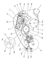
図1に示すように、充電式芝刈り機1は、本体部2、本体部2の前部にあって左右(図1の紙面に垂直な方向)一対のホイールからなる前輪6、後部にあって左右に延びる円筒状の後輪7が設けられている。本体部2の後部には、この本体部2の両側に回転可能に軸支された一対の支持柄8、この一対の支持柄8の先端部に設けられたグリップ9、グリップ部9に設けられ操作者の引き込み操作により後述のモータ14を起動するスイッチ10とからなるハンドル部11が、前後方向に所定範囲回動可能に設けられている。
As shown in FIG. 1, the rechargeable lawn mower 1 is located at the front of the main body 2 and the front of the main body 2 and in the front wheel 6 consisting of a pair of left and right wheels (in the direction perpendicular to the plane of FIG. 1). A cylindrical
さらに、ハンドル部11のグリップ部9の前方には、後述のモータ14を制御する図示を省略した制御装置を収納し、バッテリの残量などを表示する表示部を設けた制御ボックス12が設けられている。このように、制御ボックス12を本体部2から離れた位置に設けることにより、モータ14からの熱や、切り屑などの塵から制御装置などを保護しやすくなっている。
Further, in front of the grip portion 9 of the
本体部2の後端には、切断した芝草を収納するグラスキャッチャー13が着脱可能に取付けられている。
A
次に、本体部2は、図1、図2に示すように、その回転軸14aを左右方向(図1、図2の紙面に垂直な方向)に配置して設けられたモータ14と、このモータ14の回転軸14aに平行に設けられ、図示を省略したベルトとプーリーを介して駆動されるリール刃式のカッター15とを収納しているカッターハウジング3と、このカッターハウジング3の上面を覆うハウジングカバー4、および、このハウジングカバー4の上面を覆う上部カバー5から構成されている。
Next, as shown in FIGS. 1 and 2, the main body 2 includes a
上記カッターハウジング3は、その下方(地面側)と後方が開口した箱状体であり、下方の開口には、上記カッター15が上下方向にその取り付け位置を調整可能に取付けられている。後方の開口3bからは、カッター15が切断した芝草が上記グラスキャッチャー13に排出される。
The
カッターハウジング3の上部は前方から後方に至る天板3aで形成されていて、その一部が開口し、その開口部には、モータ支持板20が図示を省略したねじにより固定され開口を塞いでいる。このモータ支持板20の上部には、内部にモータ14を収納した2つ割りのモータハウジング21が図示を省略したねじにより固定されている。モータハウジング21には、モータ14を冷却するための図示を省略した通風路が形成されている。この通風路は、カッターハウジング3と、このカッターハウジング3の上面を覆うハウジングカバー4とで形成された空間22に通じ、さらに、上記ハウジングカバー4の側面に形成された冷却風取入口4eに通じ、外部から冷却風を取入れている。上記モータ14の回転は、モータ14の回転軸14aに固定された図示を省略した小プーリーと、同じくカッターの回転軸15aに固定された図示を省略した大プーリーと、同じく図示を省略したベルトを介して伝達され、カッター15を駆動する。
The upper part of the
上記カッターハウジング3の天板3aの上面は、下方が開口した箱状体からなるハウジングカバー4で覆われている。このハウジングカバー4は、開口側を下にして複数本のねじ42にてカッターハウジング3の天板3aに固定されている。また、ハウジングカバー4の後端部には、上記グラスキャッチャー13を係止するためのフック部4bが一体に形成されている。
The top surface of the
ハウジングカバー4の天板4aの後方上面には、内部にパック電池17を収納したバッテリパック16の端子と、前記制御装置につながる電力線とを接続するための端子を備えた端子ボックス41が、ねじ43で固定されている。この端子ボックス41の端子にバッテリパック16の接続端子を挿入、あるいは、離脱させることでバッテリパック16の着脱を行う。なお、バッテリパック16は本発明におけるバッテリに相当する。
On the rear upper surface of the
ハウジングカバー4の天板4aの略中央から後端に至る上面には、一方の側面を傾斜面4dに、他方の側面を垂直に形成した凸部4cが、上記バッテパック16の全周を囲む範囲に形成されている。
On the top surface of the
上記ハウジングカバー4の天板4aの上面は、下方が開口した略お椀状の上部カバー5で覆われている。この上部カバー5の開口側である内側の略中央から後端に至る面には、ハウジングカバー4の天板4aの上面に向けて、上記ハウジングカバー4の天板4aに形成された凸部4cに対向する位置に、垂直な壁5aが形成されている。この垂直な壁5aの下端は、傾斜面5bに形成されている。この上部カバー5の壁5aの傾斜面5bと上記ハウジングカバー4の凸部4cの傾斜面4dとを嵌め合わせることでインローを構成し、密着している。
The upper surface of the
なお、本実施例でのインローは、上記ハウジングカバー4の天板4aの上面に一方の側面を傾斜面とする凸部4cを形成し、上部カバー5の壁5aの下端に傾斜面5bを形成したものであるが、ハウジングカバー4の天板4aの上面にV溝を形成し、壁5aの下端をV字形状にしてもよいし、ハウジングカバー4の天板4aの上面に逆V字の凸部を形成し、壁5aの下端に逆V字溝を形成してもよく、インローの形状は特に限定するものではない。
The spigot in this embodiment forms a
また、上部カバー5の後端の両側には、一対の支持軸5dが一体に形成されている。この支持軸5dは、上記ハウジングカバー4の後端に形成され図示を省略した一対の孔に回動可能に挿入されている。そして、上部カバー5は、この支持軸5dを中心に上下に回動する。
さらに、上部カバー5の先端には、係止突起5cが一体に形成されている。一方、ハウジングカバー4の先端にあって、上記係止突起5cに対向する位置には、係止レバー19が支軸19aを中心に回動可能に設けられている。この係止レバー19には、上記係止突起5cが係合する係止凹部19bが形成されている。また、係止レバー19は、上部カバー5が閉じられている状態で、上記係止凹部19bに係止突起5cが確実に係合するべく、ばね19cにより、支軸19aを中心にして、常時、図中、時計回り方向に付勢されている。
Further, a pair of
Further, a
バッテリパック16を取り出す場合には、係止レバー19の係止凹部19bとは反対側の端部を押し下げ、回動し、係止凹部19bから係止突起5cを解除した後、上部カバー5を持ち上げ、回動させて開き、バッテリパック16を取り出し可能とする。
When the
このように、本発明のバッテリパック16の収納室18は、ハウジングカバー4の天板4aの上面、この上面に形成されたバッテリパック16の全周を囲む範囲の凸部4c、上部カバー5、この上部カバー5の内側にあって上記バッテリパック16の凸部4cに対向する位置に形成された壁5aにより形成され、さらに、上記凸部4cの傾斜面4dと壁5aの下端の傾斜面5bとでインローを構成している。
As described above, the
このインローの嵌め合わせにより、本発明のバッテリパック16の収納室18は、ハウジングカバー4や上部カバー5などの部品の寸法に多少のバラツキが生じても、確実に密閉状態を確保できるので、雨水や塵埃からバッテリパック16を保護できる。
By fitting the spigot, the
また、本発明のバッテリパック16の収納室18は、カッター15から、カッターハウジング3の天板3aと、この天板3aの上面に設けられたハウジングカバー4の天板4aとにより2重に隔離されているので、カッター15の濡れた芝草の切断による水や、切り屑などの塵が内部に侵入するのを確実に防止できる。
さらに、モータ14からは、ハウジングカバー4の天板4aにて隔離されているので、モータ14の熱からもバッテリパック16を確実に保護できる。
Further, the
Furthermore, since it is isolated from the
本実施例では、本発明をリール刃式のカッターを有する充電式芝刈り機や、モータを横に配置した(モータの回転軸を地面に平行に配置した)充電式芝刈り機に採用したが、円盤状のカッターを有する充電式芝刈り機や、モータを縦に配置した(モータの回転軸を地面に垂直に配置した)充電式芝刈り機にも適用できる。 In this embodiment, the present invention is applied to a rechargeable lawnmower having a reel blade type cutter or a rechargeable lawnmower in which a motor is disposed horizontally (the rotation axis of the motor is disposed parallel to the ground). The present invention can also be applied to a rechargeable lawn mower having a disk-shaped cutter, and a rechargeable lawn mower in which a motor is arranged vertically (the rotation axis of the motor is arranged perpendicular to the ground).
1 充電式芝刈り機、2 本体部、3 カッターハウジング、4 ハウジングカバー、4d 傾斜面、5 上部カバー、5b 傾斜面、16 バッテリパック(バッテリ)、18 収納室
DESCRIPTION OF SYMBOLS 1 Rechargeable lawn mower, 2 main part, 3 cutter housing, 4 housing cover, 4d inclined surface, 5 upper cover, 5b inclined surface, 16 battery pack (battery), 18 storage chamber
Claims (2)
該カッターを収納するカッターハウジングの上面をハウジングカバーで覆うとともに、下方に開口を有する上部カバーが該ハウジングカバーの上面を覆うように該ハウジングカバーに上下方向に回動可能に設けられており、
該ハウジングカバーの上面には、該バッテリが着脱可能に装着されるとともに該バッテリを囲む凸部が形成されており、
該上部カバーは、該バッテリと該凸部を上方から覆っており、
該ハウジングカバーの上面に装着された該バッテリの上面は、該上部カバーの回動中心側を下方として傾斜していることを特徴とする充電式芝刈り機。 In a rechargeable lawn mower having a motor that is rotated by power supply from a battery and a cutter that is driven by the rotation of the motor to cut grass.
The upper surface of the cutter housing that houses the cutter is covered with a housing cover, and an upper cover having an opening below is provided on the housing cover so as to be rotatable in the vertical direction so as to cover the upper surface of the housing cover.
On the upper surface of the housing cover, the battery is detachably mounted and a convex portion surrounding the battery is formed,
Upper cover has Tsu covering the battery and the convex portion from above,
The rechargeable lawn mower characterized in that the upper surface of the battery mounted on the upper surface of the housing cover is inclined with the rotation center side of the upper cover as a lower side .
Priority Applications (1)
| Application Number | Priority Date | Filing Date | Title |
|---|---|---|---|
| JP2014082084A JP5826883B2 (en) | 2014-04-11 | 2014-04-11 | Rechargeable lawn mower |
Applications Claiming Priority (1)
| Application Number | Priority Date | Filing Date | Title |
|---|---|---|---|
| JP2014082084A JP5826883B2 (en) | 2014-04-11 | 2014-04-11 | Rechargeable lawn mower |
Related Parent Applications (1)
| Application Number | Title | Priority Date | Filing Date |
|---|---|---|---|
| JP2008299204A Division JP5525155B2 (en) | 2008-11-25 | 2008-11-25 | Rechargeable lawn mower |
Publications (2)
| Publication Number | Publication Date |
|---|---|
| JP2014140382A JP2014140382A (en) | 2014-08-07 |
| JP5826883B2 true JP5826883B2 (en) | 2015-12-02 |
Family
ID=51422298
Family Applications (1)
| Application Number | Title | Priority Date | Filing Date |
|---|---|---|---|
| JP2014082084A Active JP5826883B2 (en) | 2014-04-11 | 2014-04-11 | Rechargeable lawn mower |
Country Status (1)
| Country | Link |
|---|---|
| JP (1) | JP5826883B2 (en) |
Families Citing this family (1)
| Publication number | Priority date | Publication date | Assignee | Title |
|---|---|---|---|---|
| JP2021023186A (en) * | 2019-08-02 | 2021-02-22 | 株式会社マキタ | Lawn mower |
Family Cites Families (5)
| Publication number | Priority date | Publication date | Assignee | Title |
|---|---|---|---|---|
| US5819513A (en) * | 1993-09-22 | 1998-10-13 | Briggs & Stratton Corporation | Power head assembly for electric grass cutting device |
| JPH087860A (en) * | 1994-06-24 | 1996-01-12 | Makita Corp | Battery case |
| JPH09216648A (en) * | 1996-02-07 | 1997-08-19 | Yazaki Corp | Watertight case |
| JP3160758B2 (en) * | 1996-09-17 | 2001-04-25 | 本田技研工業株式会社 | Electric lawn mower |
| US7479754B2 (en) * | 2006-10-17 | 2009-01-20 | Desa Ip Llc | Hybrid electric lawnmower |
-
2014
- 2014-04-11 JP JP2014082084A patent/JP5826883B2/en active Active
Also Published As
| Publication number | Publication date |
|---|---|
| JP2014140382A (en) | 2014-08-07 |
Similar Documents
| Publication | Publication Date | Title |
|---|---|---|
| US9854738B2 (en) | String trimmer with adjustable guard assembly | |
| JP5525155B2 (en) | Rechargeable lawn mower | |
| JP2016049048A (en) | Lawn mower | |
| CA2913169A1 (en) | Grass trimmer | |
| TWI471087B (en) | Power tool | |
| US20210112711A1 (en) | Hand push power tool | |
| JP2021007319A (en) | Electric type hand held implement | |
| EP1435194B1 (en) | Trimmer | |
| JP2021023230A (en) | Work machine | |
| JP6034752B2 (en) | Walking mower | |
| JP5826883B2 (en) | Rechargeable lawn mower | |
| US6997268B2 (en) | Trimmer | |
| US20210029875A1 (en) | Lawn mower | |
| JP6088914B2 (en) | Walking mower | |
| US20200246998A1 (en) | Electric working machine | |
| US20200288635A1 (en) | Work machine | |
| EP3025572B1 (en) | Grass trimmer | |
| WO2021024399A1 (en) | Work machine | |
| JP5506300B2 (en) | Brush cutter | |
| JP4254854B2 (en) | Lawn mower | |
| JP2019216650A (en) | Work machine | |
| CN210610350U (en) | Garden tool | |
| WO2019034144A1 (en) | Smart mower | |
| CN112236326A (en) | Working machine | |
| JP2019216651A (en) | Work machine |
Legal Events
| Date | Code | Title | Description |
|---|---|---|---|
| A621 | Written request for application examination |
Free format text: JAPANESE INTERMEDIATE CODE: A621 Effective date: 20140509 |
|
| A977 | Report on retrieval |
Free format text: JAPANESE INTERMEDIATE CODE: A971007 Effective date: 20150227 |
|
| A131 | Notification of reasons for refusal |
Free format text: JAPANESE INTERMEDIATE CODE: A131 Effective date: 20150318 |
|
| A521 | Request for written amendment filed |
Free format text: JAPANESE INTERMEDIATE CODE: A523 Effective date: 20150513 |
|
| TRDD | Decision of grant or rejection written | ||
| A01 | Written decision to grant a patent or to grant a registration (utility model) |
Free format text: JAPANESE INTERMEDIATE CODE: A01 Effective date: 20151009 |
|
| A61 | First payment of annual fees (during grant procedure) |
Free format text: JAPANESE INTERMEDIATE CODE: A61 Effective date: 20151014 |
|
| R150 | Certificate of patent or registration of utility model |
Ref document number: 5826883 Country of ref document: JP Free format text: JAPANESE INTERMEDIATE CODE: R150 |
|
| S111 | Request for change of ownership or part of ownership |
Free format text: JAPANESE INTERMEDIATE CODE: R313111 |
|
| R350 | Written notification of registration of transfer |
Free format text: JAPANESE INTERMEDIATE CODE: R350 |
|
| S531 | Written request for registration of change of domicile |
Free format text: JAPANESE INTERMEDIATE CODE: R313531 |
|
| R350 | Written notification of registration of transfer |
Free format text: JAPANESE INTERMEDIATE CODE: R350 |