JP5824063B2 - Manufacturing method of steel parts - Google Patents
Manufacturing method of steel parts Download PDFInfo
- Publication number
- JP5824063B2 JP5824063B2 JP2013541806A JP2013541806A JP5824063B2 JP 5824063 B2 JP5824063 B2 JP 5824063B2 JP 2013541806 A JP2013541806 A JP 2013541806A JP 2013541806 A JP2013541806 A JP 2013541806A JP 5824063 B2 JP5824063 B2 JP 5824063B2
- Authority
- JP
- Japan
- Prior art keywords
- quenching
- steel
- carburizing
- carbonitriding
- bending fatigue
- Prior art date
- Legal status (The legal status is an assumption and is not a legal conclusion. Google has not performed a legal analysis and makes no representation as to the accuracy of the status listed.)
- Active
Links
Images


Classifications
-
- C—CHEMISTRY; METALLURGY
- C23—COATING METALLIC MATERIAL; COATING MATERIAL WITH METALLIC MATERIAL; CHEMICAL SURFACE TREATMENT; DIFFUSION TREATMENT OF METALLIC MATERIAL; COATING BY VACUUM EVAPORATION, BY SPUTTERING, BY ION IMPLANTATION OR BY CHEMICAL VAPOUR DEPOSITION, IN GENERAL; INHIBITING CORROSION OF METALLIC MATERIAL OR INCRUSTATION IN GENERAL
- C23C—COATING METALLIC MATERIAL; COATING MATERIAL WITH METALLIC MATERIAL; SURFACE TREATMENT OF METALLIC MATERIAL BY DIFFUSION INTO THE SURFACE, BY CHEMICAL CONVERSION OR SUBSTITUTION; COATING BY VACUUM EVAPORATION, BY SPUTTERING, BY ION IMPLANTATION OR BY CHEMICAL VAPOUR DEPOSITION, IN GENERAL
- C23C8/00—Solid state diffusion of only non-metal elements into metallic material surfaces; Chemical surface treatment of metallic material by reaction of the surface with a reactive gas, leaving reaction products of surface material in the coating, e.g. conversion coatings, passivation of metals
- C23C8/80—After-treatment
-
- C—CHEMISTRY; METALLURGY
- C21—METALLURGY OF IRON
- C21D—MODIFYING THE PHYSICAL STRUCTURE OF FERROUS METALS; GENERAL DEVICES FOR HEAT TREATMENT OF FERROUS OR NON-FERROUS METALS OR ALLOYS; MAKING METAL MALLEABLE, e.g. BY DECARBURISATION OR TEMPERING
- C21D1/00—General methods or devices for heat treatment, e.g. annealing, hardening, quenching or tempering
- C21D1/06—Surface hardening
-
- C—CHEMISTRY; METALLURGY
- C21—METALLURGY OF IRON
- C21D—MODIFYING THE PHYSICAL STRUCTURE OF FERROUS METALS; GENERAL DEVICES FOR HEAT TREATMENT OF FERROUS OR NON-FERROUS METALS OR ALLOYS; MAKING METAL MALLEABLE, e.g. BY DECARBURISATION OR TEMPERING
- C21D1/00—General methods or devices for heat treatment, e.g. annealing, hardening, quenching or tempering
- C21D1/56—General methods or devices for heat treatment, e.g. annealing, hardening, quenching or tempering characterised by the quenching agents
- C21D1/58—Oils
-
- C—CHEMISTRY; METALLURGY
- C21—METALLURGY OF IRON
- C21D—MODIFYING THE PHYSICAL STRUCTURE OF FERROUS METALS; GENERAL DEVICES FOR HEAT TREATMENT OF FERROUS OR NON-FERROUS METALS OR ALLOYS; MAKING METAL MALLEABLE, e.g. BY DECARBURISATION OR TEMPERING
- C21D9/00—Heat treatment, e.g. annealing, hardening, quenching or tempering, adapted for particular articles; Furnaces therefor
- C21D9/28—Heat treatment, e.g. annealing, hardening, quenching or tempering, adapted for particular articles; Furnaces therefor for plain shafts
-
- C—CHEMISTRY; METALLURGY
- C21—METALLURGY OF IRON
- C21D—MODIFYING THE PHYSICAL STRUCTURE OF FERROUS METALS; GENERAL DEVICES FOR HEAT TREATMENT OF FERROUS OR NON-FERROUS METALS OR ALLOYS; MAKING METAL MALLEABLE, e.g. BY DECARBURISATION OR TEMPERING
- C21D9/00—Heat treatment, e.g. annealing, hardening, quenching or tempering, adapted for particular articles; Furnaces therefor
- C21D9/30—Heat treatment, e.g. annealing, hardening, quenching or tempering, adapted for particular articles; Furnaces therefor for crankshafts; for camshafts
-
- C—CHEMISTRY; METALLURGY
- C21—METALLURGY OF IRON
- C21D—MODIFYING THE PHYSICAL STRUCTURE OF FERROUS METALS; GENERAL DEVICES FOR HEAT TREATMENT OF FERROUS OR NON-FERROUS METALS OR ALLOYS; MAKING METAL MALLEABLE, e.g. BY DECARBURISATION OR TEMPERING
- C21D9/00—Heat treatment, e.g. annealing, hardening, quenching or tempering, adapted for particular articles; Furnaces therefor
- C21D9/32—Heat treatment, e.g. annealing, hardening, quenching or tempering, adapted for particular articles; Furnaces therefor for gear wheels, worm wheels, or the like
-
- C—CHEMISTRY; METALLURGY
- C22—METALLURGY; FERROUS OR NON-FERROUS ALLOYS; TREATMENT OF ALLOYS OR NON-FERROUS METALS
- C22C—ALLOYS
- C22C38/00—Ferrous alloys, e.g. steel alloys
-
- C—CHEMISTRY; METALLURGY
- C22—METALLURGY; FERROUS OR NON-FERROUS ALLOYS; TREATMENT OF ALLOYS OR NON-FERROUS METALS
- C22C—ALLOYS
- C22C38/00—Ferrous alloys, e.g. steel alloys
- C22C38/001—Ferrous alloys, e.g. steel alloys containing N
-
- C—CHEMISTRY; METALLURGY
- C22—METALLURGY; FERROUS OR NON-FERROUS ALLOYS; TREATMENT OF ALLOYS OR NON-FERROUS METALS
- C22C—ALLOYS
- C22C38/00—Ferrous alloys, e.g. steel alloys
- C22C38/002—Ferrous alloys, e.g. steel alloys containing In, Mg, or other elements not provided for in one single group C22C38/001 - C22C38/60
-
- C—CHEMISTRY; METALLURGY
- C22—METALLURGY; FERROUS OR NON-FERROUS ALLOYS; TREATMENT OF ALLOYS OR NON-FERROUS METALS
- C22C—ALLOYS
- C22C38/00—Ferrous alloys, e.g. steel alloys
- C22C38/02—Ferrous alloys, e.g. steel alloys containing silicon
-
- C—CHEMISTRY; METALLURGY
- C22—METALLURGY; FERROUS OR NON-FERROUS ALLOYS; TREATMENT OF ALLOYS OR NON-FERROUS METALS
- C22C—ALLOYS
- C22C38/00—Ferrous alloys, e.g. steel alloys
- C22C38/04—Ferrous alloys, e.g. steel alloys containing manganese
-
- C—CHEMISTRY; METALLURGY
- C22—METALLURGY; FERROUS OR NON-FERROUS ALLOYS; TREATMENT OF ALLOYS OR NON-FERROUS METALS
- C22C—ALLOYS
- C22C38/00—Ferrous alloys, e.g. steel alloys
- C22C38/06—Ferrous alloys, e.g. steel alloys containing aluminium
-
- C—CHEMISTRY; METALLURGY
- C22—METALLURGY; FERROUS OR NON-FERROUS ALLOYS; TREATMENT OF ALLOYS OR NON-FERROUS METALS
- C22C—ALLOYS
- C22C38/00—Ferrous alloys, e.g. steel alloys
- C22C38/18—Ferrous alloys, e.g. steel alloys containing chromium
- C22C38/22—Ferrous alloys, e.g. steel alloys containing chromium with molybdenum or tungsten
-
- C—CHEMISTRY; METALLURGY
- C22—METALLURGY; FERROUS OR NON-FERROUS ALLOYS; TREATMENT OF ALLOYS OR NON-FERROUS METALS
- C22C—ALLOYS
- C22C38/00—Ferrous alloys, e.g. steel alloys
- C22C38/18—Ferrous alloys, e.g. steel alloys containing chromium
- C22C38/26—Ferrous alloys, e.g. steel alloys containing chromium with niobium or tantalum
-
- C—CHEMISTRY; METALLURGY
- C23—COATING METALLIC MATERIAL; COATING MATERIAL WITH METALLIC MATERIAL; CHEMICAL SURFACE TREATMENT; DIFFUSION TREATMENT OF METALLIC MATERIAL; COATING BY VACUUM EVAPORATION, BY SPUTTERING, BY ION IMPLANTATION OR BY CHEMICAL VAPOUR DEPOSITION, IN GENERAL; INHIBITING CORROSION OF METALLIC MATERIAL OR INCRUSTATION IN GENERAL
- C23C—COATING METALLIC MATERIAL; COATING MATERIAL WITH METALLIC MATERIAL; SURFACE TREATMENT OF METALLIC MATERIAL BY DIFFUSION INTO THE SURFACE, BY CHEMICAL CONVERSION OR SUBSTITUTION; COATING BY VACUUM EVAPORATION, BY SPUTTERING, BY ION IMPLANTATION OR BY CHEMICAL VAPOUR DEPOSITION, IN GENERAL
- C23C8/00—Solid state diffusion of only non-metal elements into metallic material surfaces; Chemical surface treatment of metallic material by reaction of the surface with a reactive gas, leaving reaction products of surface material in the coating, e.g. conversion coatings, passivation of metals
- C23C8/06—Solid state diffusion of only non-metal elements into metallic material surfaces; Chemical surface treatment of metallic material by reaction of the surface with a reactive gas, leaving reaction products of surface material in the coating, e.g. conversion coatings, passivation of metals using gases
- C23C8/08—Solid state diffusion of only non-metal elements into metallic material surfaces; Chemical surface treatment of metallic material by reaction of the surface with a reactive gas, leaving reaction products of surface material in the coating, e.g. conversion coatings, passivation of metals using gases only one element being applied
- C23C8/20—Carburising
- C23C8/22—Carburising of ferrous surfaces
-
- C—CHEMISTRY; METALLURGY
- C23—COATING METALLIC MATERIAL; COATING MATERIAL WITH METALLIC MATERIAL; CHEMICAL SURFACE TREATMENT; DIFFUSION TREATMENT OF METALLIC MATERIAL; COATING BY VACUUM EVAPORATION, BY SPUTTERING, BY ION IMPLANTATION OR BY CHEMICAL VAPOUR DEPOSITION, IN GENERAL; INHIBITING CORROSION OF METALLIC MATERIAL OR INCRUSTATION IN GENERAL
- C23C—COATING METALLIC MATERIAL; COATING MATERIAL WITH METALLIC MATERIAL; SURFACE TREATMENT OF METALLIC MATERIAL BY DIFFUSION INTO THE SURFACE, BY CHEMICAL CONVERSION OR SUBSTITUTION; COATING BY VACUUM EVAPORATION, BY SPUTTERING, BY ION IMPLANTATION OR BY CHEMICAL VAPOUR DEPOSITION, IN GENERAL
- C23C8/00—Solid state diffusion of only non-metal elements into metallic material surfaces; Chemical surface treatment of metallic material by reaction of the surface with a reactive gas, leaving reaction products of surface material in the coating, e.g. conversion coatings, passivation of metals
- C23C8/06—Solid state diffusion of only non-metal elements into metallic material surfaces; Chemical surface treatment of metallic material by reaction of the surface with a reactive gas, leaving reaction products of surface material in the coating, e.g. conversion coatings, passivation of metals using gases
- C23C8/28—Solid state diffusion of only non-metal elements into metallic material surfaces; Chemical surface treatment of metallic material by reaction of the surface with a reactive gas, leaving reaction products of surface material in the coating, e.g. conversion coatings, passivation of metals using gases more than one element being applied in one step
- C23C8/30—Carbo-nitriding
- C23C8/32—Carbo-nitriding of ferrous surfaces
-
- F—MECHANICAL ENGINEERING; LIGHTING; HEATING; WEAPONS; BLASTING
- F16—ENGINEERING ELEMENTS AND UNITS; GENERAL MEASURES FOR PRODUCING AND MAINTAINING EFFECTIVE FUNCTIONING OF MACHINES OR INSTALLATIONS; THERMAL INSULATION IN GENERAL
- F16H—GEARING
- F16H55/00—Elements with teeth or friction surfaces for conveying motion; Worms, pulleys or sheaves for gearing mechanisms
- F16H55/32—Friction members
- F16H55/34—Non-adjustable friction discs
-
- F—MECHANICAL ENGINEERING; LIGHTING; HEATING; WEAPONS; BLASTING
- F16—ENGINEERING ELEMENTS AND UNITS; GENERAL MEASURES FOR PRODUCING AND MAINTAINING EFFECTIVE FUNCTIONING OF MACHINES OR INSTALLATIONS; THERMAL INSULATION IN GENERAL
- F16H—GEARING
- F16H55/00—Elements with teeth or friction surfaces for conveying motion; Worms, pulleys or sheaves for gearing mechanisms
- F16H55/02—Toothed members; Worms
- F16H55/06—Use of materials; Use of treatments of toothed members or worms to affect their intrinsic material properties
Description
本発明は、鋼製部品の製造方法に関する。詳しくは、本発明は、切削加工工程における被削性またはネットシェイプ成形時の冷間鍛造性に優れ、かつ浸炭焼入れまたは浸炭窒化焼入れ後の高サイクルおよび低サイクルの曲げ疲労強度、ならびに耐ピッチング強度に優れた、鋼製の動力伝達部品の製造方法に関する。 The present invention relates to a method for manufacturing a steel part. Specifically, the present invention is excellent in machinability in the cutting process or cold forgeability at the time of net shape molding, and has high cycle and low cycle bending fatigue strength after carburizing quenching or carbonitriding quenching, and pitting resistance. The present invention relates to a method for manufacturing a power transmission component made of steel, which is superior to the above.
自動車および産業機械の鋼製部品、なかでも動力伝達部品として使用される鋼製の歯車、プーリ、シャフト等には、通常、高周波焼入れ、浸炭焼入れ、浸炭窒化焼入れ等の「表面硬化処理」が施される。 Steel parts of automobiles and industrial machinery, especially steel gears, pulleys, shafts, etc. used as power transmission parts are usually subjected to “surface hardening” such as induction hardening, carburizing and carbonitriding. Is done.
上記のうちで、「高周波焼入れ」は、Ac3点以上の高温のオーステナイト域に急速加熱した後、冷却して焼入れする処理である。高周波焼入れは、硬化層深さの調整が比較的容易であるという長所を有する。必要な表面硬さ、硬化層深さおよび芯部硬さを得るために、被処理材には、例えば、JIS G 4051(2009)に規定されたS45C、JIS G 4053(2008)に規定されたSCr440等の中炭素鋼を使用するのが一般的である。Among the above, “high-frequency quenching” is a process of rapidly heating to a high temperature austenite region of Ac 3 points or higher, and then cooling and quenching. Induction hardening has the advantage that the depth of the hardened layer is relatively easy to adjust. In order to obtain the required surface hardness, hardened layer depth and core hardness, the material to be treated is, for example, S45C defined in JIS G 4051 (2009), JIS G 4053 (2008). It is common to use medium carbon steel such as SCr440.
しかしながら、中炭素鋼は素材硬さが低炭素鋼に比べて高いため、切削加工工程における被削性に劣るとともに、ネットシェイプ成形時の冷間鍛造性にも劣る。加えて、高周波焼入れの場合には、部品ごとに高周波加熱コイルを作製しなければならないという問題もある。 However, since medium carbon steel is higher in material hardness than low carbon steel, it is inferior in machinability in the cutting process and in cold forgeability at the time of net shape forming. In addition, in the case of induction hardening, there is also a problem that an induction heating coil must be manufactured for each part.
このため、上記鋼製部品の表面硬化処理として、浸炭焼入れまたは浸炭窒化焼入れを用いることが増えている。 For this reason, carburizing quenching or carbonitriding quenching is increasingly used as the surface hardening treatment for the steel parts.
表面硬化処理として浸炭焼入れまたは浸炭窒化焼入れを用いる場合、上記の鋼製部品は、例えば、次に示す方法によって製造される。 When carburizing quenching or carbonitriding quenching is used as the surface hardening treatment, the steel part is manufactured by, for example, the following method.
〈1〉機械構造用鋼からなる圧延棒鋼または線材を準備する。上記の機械構造用鋼としては、高周波焼入れに用いる鋼に比べてC含有量が低い鋼、例えば、JIS G 4053(2008)に規定されたSCr420、SCM420およびSNCM420等が用いられる。 <1> A rolled steel bar or wire made of steel for machine structure is prepared. As the steel for machine structure, steel having a lower C content than steel used for induction hardening, for example, SCr420, SCM420 and SNCM420 defined in JIS G 4053 (2008) are used.
〈2〉準備した圧延棒鋼または線材を熱間鍛造して中間製品に粗成形する。 <2> The prepared rolled steel bar or wire is hot forged and roughly formed into an intermediate product.
〈3〉上記〈2〉の粗成形した中間製品に対して、必要に応じて焼準処理を実施した後、切削加工を施す。
〈3’〉上記〈2〉の粗成形した中間製品に対して、必要に応じて焼準処理を実施した後、冷間鍛造によるネットシェイプ成形を施すこともある。<3> The intermediate product of the above <2> is subjected to a normalizing treatment as necessary and then subjected to cutting.
<3 ′> After performing the normalizing treatment on the roughly formed intermediate product of <2> as necessary, net shape molding by cold forging may be performed.
〈4〉切削加工またはネットシェイプ成形を施した中間製品に対して、表面硬化処理として浸炭焼入れまたは浸炭窒化焼入れを行い、必要に応じて、さらに200℃以下の温度で焼戻しを実施して、前記鋼製部品を得る。 <4> Carrying quenching or carbonitriding and quenching as surface hardening treatment is performed on the intermediate product subjected to cutting or net shape molding, and if necessary, further tempering at a temperature of 200 ° C. or less, Obtain steel parts.
〈5〉上記〈4〉の表面硬化処理の後、または焼戻しの後、さらに、ショットピーニングおよび/または表面研削を施して鋼製部品を得ることもある。 <5> The steel part may be obtained by performing shot peening and / or surface grinding after the surface hardening treatment of <4> or after tempering.
近年、例えば、自動車および産業機械の燃費を向上させるために、または、エンジンの高出力化を実現するために、鋼製部品の軽量化および小型化が進んでいる。しかし、軽量化および小型化によって、鋼製部品にかかる負荷は増大する傾向にある。そのため、鋼製部品には、高サイクル域での曲げ疲労強度の向上ならびに、低サイクル域での曲げ疲労強度および耐ピッチング強度の向上が求められている。 In recent years, for example, in order to improve the fuel efficiency of automobiles and industrial machines, or to achieve higher engine output, steel parts have been reduced in weight and size. However, the load on steel parts tends to increase due to the reduction in weight and size. For this reason, steel parts are required to have improved bending fatigue strength in a high cycle range and improved bending fatigue strength and pitting resistance in a low cycle range.
具体的には、例えば、自動車用歯車の場合、歯元においては、定常運転時等での歯元折損を抑制する点から、負荷繰返し数1.0×10⁷回程度の高サイクル域でのより大きい曲げ疲労強度が要求され、また、運転開始時に入力される大負荷での歯元折損を抑制する点から、負荷繰返し数1.0×10⁵回程度の低サイクル域でのより大きい曲げ疲労強度も要求されている。さらに、歯面においては、歯車噛み合い時の騒音抑制およびはく離部を起点とした歯の折損を抑制する点から、より大きい耐ピッチング強度が要求されている。Specifically, for example, in the case of a gear for an automobile, in the tooth root, in a high cycle region where the load repetition number is about 1.0 × 10 7 times from the viewpoint of suppressing tooth root breakage during steady operation or the like. Greater bending fatigue strength is required, and greater bending in a low cycle range with a load repetition rate of about 1.0 × 10 5 is possible from the viewpoint of suppressing tooth root breakage under heavy loads input at the start of operation. Fatigue strength is also required. Further, the tooth surface is required to have a higher pitching resistance from the viewpoint of suppressing noise during gear engagement and suppressing tooth breakage starting from the peeling portion.
以下、上記の高サイクル域での曲げ疲労強度を「高サイクル曲げ疲労強度」といい、低サイクル域での曲げ疲労強度を「低サイクル曲げ疲労強度」という。 Hereinafter, the bending fatigue strength in the high cycle region is referred to as “high cycle bending fatigue strength”, and the bending fatigue strength in the low cycle region is referred to as “low cycle bending fatigue strength”.
こうした要求に応えるために、上記JIS G 4053(2008)に規定された機械構造用鋼に比べて合金元素を多く含有した鋼を用いて、浸炭焼入れまたは浸炭窒化焼入れによって表面硬化処理を施す技術および、表面硬化処理後さらにショットピーニングを施す技術が提案されている。 In order to meet such demands, a technique for performing surface hardening treatment by carburizing quenching or carbonitriding quenching using steel containing a larger amount of alloying elements than steel for machine structure defined in JIS G 4053 (2008), and In addition, a technique for performing shot peening after the surface hardening treatment has been proposed.
特許文献1に、Si:0.1%以下、Ni:0.4〜0.6%、Mo:0.6〜1.0%およびNb:0.02〜0.5%などの元素を含み、残部はFeであり、浸炭異常層が6μm以下で、No.9以上の結晶粒度を有する素材によって構成された「歯車」が開示されている。
特許文献2に、C:0.10〜0.40%、Si:0.06%以上0.15%未満、Mn:0.30〜1.00%、Cr:0.90〜1.20%、Mo:0.30%を超えて0.50%以下で、残部がFeからなる鋼を、浸炭焼入れまたは浸炭窒化焼入れし、次いでショットピーニングを施す「熱処理鋼部品の製造方法」が開示されている。
In
特許文献3に、Cr:0.40〜1.50%、Si:0.10%以下などの元素を含み、必要に応じてさらに、Ni:2.50%以下、Mo:0.40%以下、Nb:0.005〜0.025%のうちの1種以上を含有し、残部が実質上Feからなる「浸炭処理して用いる歯車用鋼」が開示されている。
特許文献4に、Si:1.0%以下、Cr:1.50〜5.0%などの元素を含み、残部がFeおよび不純物からなる「歯面強度の優れた歯車用鋼」および、該歯車用鋼を用いて浸炭焼入れ焼戻しまたは浸炭窒化焼入れ焼戻しの表面硬化処理を行うか、必要に応じて該表面硬化処理後、さらにショットピーニングを行う「歯面強度の優れた歯車の製造方法」が開示されている。
特許文献5に、Si:0.35〜3.0%、Cr:0.3〜5.0%、V:0.05〜0.5%などの元素を含み、必要に応じてさらに、Ni:3.0%以下、Mo:1.0%以下、Nb:0.1%以下のうちの1種以上を含有し、残部がFeおよび不可避的不純物からなる「浸炭歯車用鋼」が開示されている。
一般に、鋼は、合金元素含有量の増加に伴って硬さが高くなるので、被削性の低下が生じ、ネットシェイプ成形時の冷間鍛造性も低下する。これは、特許文献1〜5で提案された合金元素を多く含有する鋼においても同様である。
In general, since the hardness of steel increases as the alloying element content increases, the machinability decreases, and the cold forgeability during net shape forming also decreases. The same applies to steels containing many alloying elements proposed in
したがって、特許文献1〜5で提案された鋼を用いる場合には、鋼製部品製造の切削加工工程における被削性の低下を避けるために、あるいは、ネットシェイプ成形時の冷間鍛造性の低下を避けるために、切削加工またはネットシェイプ成形の前に、軟化熱処理の工程を追加する必要がある。このため、工程が増加して生産性の低下を招くことに加えて、部品製造コストも上昇してしまう。 Therefore, when using the steel proposed by patent documents 1-5, in order to avoid the fall of the machinability in the cutting process of steel parts manufacture, or the fall of the cold forgeability at the time of net shape forming In order to avoid this, it is necessary to add a softening heat treatment step before cutting or net shape forming. For this reason, in addition to an increase in the number of processes and a decrease in productivity, the part manufacturing cost also increases.
さらに、近年の合金元素の高騰に鑑みて、特に、NiおよびMoの含有量を少なくして、素材コストを低減したいという要望が大きくなっている。 Furthermore, in view of the recent surge in alloying elements, there is a growing demand for reducing the material cost, particularly by reducing the Ni and Mo contents.
特許文献1で提案された技術は、Ni:0.4〜0.6%、Mo:0.6〜1.0%およびNb:0.02〜0.5%を必須の元素として含む必要がある。このため、上記素材コスト低減という要望に対しても十分には応えることができない。
The technique proposed in
特許文献2で提案された技術は、適正条件でショットピーニングを施すものである。このため、その表3に示されているように、高サイクル曲げ疲労強度の向上は達成できる。しかしながら、低サイクル曲げ疲労については配慮されていない。したがって、鋼製部品の軽量化および小型化に伴う低サイクル曲げ疲労強度の向上という要望に対しても十分には応えることができない。
The technique proposed in
特許文献3〜5で提案された技術によれば、浸炭焼入れまたは浸炭窒化焼入れによって、良好な曲げ疲労強度および面疲労強度を達成することはできる。しかしながら、前述のように被削性の低下またはネットシェイプ成形時の冷間鍛造性の低下を避けることが難しい。つまり、相反する特性である曲げ疲労強度および面疲労強度と、被削性または冷間鍛造性とを、高いレベルで両立させることはできない。
According to the techniques proposed in
本発明は、上記現状に鑑みてなされたもので、素材コスト抑制のために高価な合金元素の含有量を少なくする一方、鋼製部品に対しては優れた、高サイクル曲げ疲労強度、低サイクル曲げ疲労強度および耐ピッチング強度を具備させることができ、しかも、部品製造時の、切削加工工程においては十分な被削性を、あるいは、ネットシェイプ成形工程においては十分な冷間鍛造性を、確保することが可能であり、さらに、浸炭焼入れまたは浸炭窒化焼入れ時の熱処理ひずみのバラツキを抑制することも可能な、鋼製部品の製造方法、なかでも歯車、プーリ、シャフト等鋼製の動力伝達部品の製造方法を提供することを目的とする。 The present invention has been made in view of the above-mentioned present situation, while reducing the content of expensive alloy elements to suppress material costs, while being excellent for steel parts, high cycle bending fatigue strength, low cycle Bending fatigue strength and pitting resistance can be achieved, and sufficient machinability is ensured in the cutting process during component manufacturing, or sufficient cold forgeability is ensured in the net shape forming process. Further, it is possible to suppress the variation in heat treatment strain during carburizing and quenching or carbonitriding and quenching, and a method for manufacturing steel parts, in particular, power transmission parts made of steel such as gears, pulleys, and shafts. It aims at providing the manufacturing method of.
本発明者らは、前記した課題を解決するために、調査、研究を重ねた。その結果、下記(a)〜(n)の知見を得た。 In order to solve the above-described problems, the present inventors have conducted research and research. As a result, the following findings (a) to (n) were obtained.
(a)切削加工時に良好な被削性を、あるいは、ネットシェイプ成形時に良好な冷間鍛造性を、確保するためには、切削加工あるいはネットシェイプ成形する前の組織、すなわち、熱間鍛造後の組織、または熱間鍛造後に焼準処理を施す場合には焼準後の組織が、安定的にフェライトとパーライトとの混合組織である必要がある。ベイナイトが混じると、硬さが増大して切削抵抗が高くなって被削性が低下し、また、変形抵抗が高くなって冷間鍛造性が低下する。 (A) In order to ensure good machinability at the time of cutting or good cold forgeability at the time of net shape forming, the structure before cutting or net shape forming, that is, after hot forging In the case where the normalizing treatment is performed after hot forging, the normalized structure needs to be a stable mixed structure of ferrite and pearlite. When bainite is mixed, the hardness increases and the cutting resistance increases, and the machinability decreases, and the deformation resistance increases and the cold forgeability decreases.
(b)部品表層からき裂が発生することによって低サイクル曲げ疲労強度が低下する。このため、低サイクル曲げ疲労強度を高めるには、負荷時のき裂発生ひずみを抑制することと、部品表層においてき裂が発生する限界の強度(以下、「き裂発生強度」という。)を高めることの2つが重要である。負荷時のき裂発生ひずみを抑制するためには、部品の芯部硬さ(部品の生地の硬さ)を増大させることが有効である。 (B) The low cycle bending fatigue strength decreases due to the generation of cracks from the component surface layer. For this reason, in order to increase the low cycle bending fatigue strength, the crack initiation strain at the time of loading is suppressed, and the limit strength (hereinafter referred to as “crack initiation strength”) at which cracks are generated in the component surface layer. Two things to raise are important. In order to suppress cracking strain at the time of loading, it is effective to increase the core hardness of the component (the hardness of the fabric of the component).
(c)部品の芯部硬さを増大させるためには、Moおよび/またはNiの含有量を高めることが効果的である。しかし、これらの元素の含有量が高すぎると、熱間鍛造後の組織、または熱間鍛造後に焼準処理を施す場合には焼準後の組織に、ベイナイトが混じりやすくなるので、被削性および冷間鍛造性が低下する。このため、低サイクル曲げ疲労強度と、被削性あるいは冷間鍛造性とを、高いレベルで両立させることは難しい。すなわち、芯部硬さの増大は、他の手段で実現することが重要である。 (C) In order to increase the core hardness of the component, it is effective to increase the content of Mo and / or Ni. However, if the content of these elements is too high, bainite is likely to be mixed in the microstructure after hot forging, or when normalizing after hot forging, the machinability And cold forgeability falls. For this reason, it is difficult to achieve both low cycle bending fatigue strength and machinability or cold forgeability at a high level. That is, it is important to increase the core hardness by other means.
(d)部品表層におけるき裂発生強度を高めるためには、第1に、粒界酸化深さを低減することが重要である。このためには、Si含有量を低減することが有効であるが、それだけでは不十分であり、CrとMnの含有量の比、つまり「Cr/Mn」の範囲も管理する必要がある。 (D) In order to increase the crack initiation strength in the component surface layer, first, it is important to reduce the grain boundary oxidation depth. For this purpose, it is effective to reduce the Si content, but that is not sufficient, and the ratio of the Cr and Mn contents, that is, the range of “Cr / Mn” needs to be managed.
(e)部品表層におけるき裂発生強度を高めるためには、粒界に存在する不純物を低減することも必要である。上記の「粒界に存在する不純物」とは、例えば、粒界に偏析するPおよび、浸炭焼入れまたは浸炭窒化焼入れの際に粒界に生じるセメンタイトなどを指す。 (E) In order to increase the crack initiation strength in the component surface layer, it is also necessary to reduce impurities present at the grain boundaries. The above-mentioned “impurities existing at grain boundaries” refer to, for example, P segregating at grain boundaries and cementite generated at grain boundaries during carburizing or carbonitriding.
(f)浸炭焼入れまたは浸炭窒化焼入れは、通常、温度が100〜150℃程度の油を用いて行われる。しかしながら、上記温度の油を用いた場合には、焼入れ処理中に自己焼戻しを受けて、粒界にフィルム状のセメンタイトが生成することがある。このフィルム状のセメンタイトが存在すると粒界強度が低下するので、低サイクル曲げ疲労強度が向上しない。しかも、自己焼戻しを受けた鋼を200℃程度の温度で焼戻しすると、Pがセメンタイトと粒界の界面に偏析しやすくなり、一層粒界強度が低下するので、低サイクル曲げ疲労強度が向上しない。すなわち、低サイクル曲げ疲労強度を高めるためには、浸炭焼入れまたは浸炭窒化焼入れ中に自己焼戻しを受けないように急冷することが重要である。浸炭焼入れまたは浸炭窒化焼入れの際に急冷することができれば、MoおよびNiの含有量をそれほど高くしなくても芯部硬さを増大することもできる。 (F) Carburizing quenching or carbonitriding quenching is usually performed using oil having a temperature of about 100 to 150 ° C. However, when oil at the above temperature is used, film-like cementite may be generated at the grain boundary due to self-tempering during the quenching process. When this film-like cementite is present, the grain boundary strength is lowered, so the low cycle bending fatigue strength is not improved. Moreover, if the steel that has undergone self-tempering is tempered at a temperature of about 200 ° C., P tends to segregate at the interface between cementite and grain boundaries, and the grain boundary strength further decreases, so the low cycle bending fatigue strength does not improve. That is, in order to increase the low cycle bending fatigue strength, it is important to rapidly cool so as not to undergo self-tempering during carburizing or carbonitriding. If quenching can be performed at the time of carburizing or carbonitriding, the core hardness can be increased without increasing the contents of Mo and Ni so much.
(g)低サイクル曲げ疲労強度の場合と同様に、部品表層におけるき裂発生強度を高めることによって、高サイクル曲げ疲労強度が向上する。したがって、高サイクル曲げ疲労強度を高めるためには、粒界酸化深さを低減する必要がある。つまり、前述のSi含有量の低減に加えて、CrとMnの含有量の比、つまり「Cr/Mn」の範囲を管理する必要がある。 (G) As in the case of the low cycle bending fatigue strength, the high cycle bending fatigue strength is improved by increasing the crack initiation strength in the component surface layer. Therefore, to increase the high cycle bending fatigue strength, it is necessary to reduce the grain boundary oxidation depth. That is, in addition to the above-described reduction of the Si content, it is necessary to manage the ratio of the Cr and Mn contents, that is, the range of “Cr / Mn”.
(h)部品の表層硬さを増大することによっても、高サイクル曲げ疲労強度を向上させることができる。さらに、部品の表層硬さの増大は、耐ピッチング強度を高めることにもつながる。 (H) High cycle bending fatigue strength can also be improved by increasing the surface hardness of the component. Furthermore, the increase in the surface hardness of the component leads to an increase in the pitting resistance.
(i)部品の表層硬さを増大するためには、浸炭焼入れまたは浸炭窒化焼入れ時に生じる部品表層部の粒界酸化物近傍における不完全焼入れ組織を低減するのがよい。 (I) In order to increase the surface hardness of the component, it is preferable to reduce the incompletely quenched structure in the vicinity of the grain boundary oxide of the component surface layer portion generated during carburizing or carbonitriding.
(j)部品表層部の粒界酸化物近傍に生じる不完全焼入れ組織は、パーライトおよび/またはベイナイトである。浸炭焼入れまたは浸炭窒化焼入れの冷却中にパーライトが生じるのは、500〜600℃付近を緩冷却したときである。このため、上記の温度域を急冷することでパーライトの生成を抑制することができる。 (J) The incompletely quenched structure generated in the vicinity of the grain boundary oxide in the part surface layer is pearlite and / or bainite. The formation of pearlite during the cooling of the carburizing quenching or the carbonitriding quenching occurs when the temperature in the vicinity of 500 to 600 ° C. is slowly cooled. For this reason, the production | generation of pearlite can be suppressed by quenching said temperature range.
(k)部品は焼入れ時に、「膜沸騰熱伝達」、「核沸騰熱伝達」および「対流熱伝達」の各段階を経て冷却される。上記3つの段階のうちで最も冷却能が高いのは「核沸騰熱伝達」である。このため、「核沸騰熱伝達」の段階を広い温度範囲とすることによって、部品表層部の冷却速度を大きくすることができる。 (K) During quenching, the part is cooled through the stages of “film boiling heat transfer”, “nucleate boiling heat transfer” and “convection heat transfer”. Among the above three stages, “nuclear boiling heat transfer” has the highest cooling capacity. For this reason, the cooling rate of the component surface layer can be increased by setting the stage of “nucleate boiling heat transfer” to a wide temperature range.
(l)「核沸騰熱伝達」の段階の温度範囲を広くするためには、「対流熱伝達」段階の開始温度を低くすることが重要であり、このためには焼入れ油の動粘度を低くする必要がある。「対流熱伝達」段階の開始温度を低くすることにより、マルテンサイト変態が開始する温度であるMs点近傍の冷却速度を大きくすることが可能なため、ベイナイトの生成を抑制することができる。 (L) In order to widen the temperature range of the “nucleate boiling heat transfer” stage, it is important to lower the starting temperature of the “convection heat transfer” stage. For this purpose, the kinematic viscosity of the quenching oil is lowered. There is a need to. By lowering the start temperature of the “convection heat transfer” stage, the cooling rate in the vicinity of the Ms point, which is the temperature at which martensitic transformation starts, can be increased, so that the formation of bainite can be suppressed.
(m)焼入れ油の動粘度を変更した場合の懸案事項は、焼入れで生じる熱処理ひずみのバラツキ量である。しかしながら、後述の実施例で一例を示すように、動粘度が低く「対流熱伝達」段階の開始温度が低い焼入れ油を用いた場合でも、焼入れで生じる熱処理ひずみのバラツキ量は、100〜150℃程度の温度で用いられる動粘度の高い従来の焼入れ油を用いた場合と同程度である。さらに、動粘度が低く「対流熱伝達」段階の開始温度が低い焼入れ油を用いた場合には、鋼中にMoをそれほど含有せず、またNiを含有しなくても、部品表層部の粒界酸化物近傍における不完全焼入れ組織の生成を抑制することができる。 (M) A matter of concern when changing the kinematic viscosity of the quenching oil is the amount of variation in heat treatment strain caused by quenching. However, as shown in an example in the examples described later, even when a quenching oil having a low kinematic viscosity and a low starting temperature in the “convection heat transfer” stage is used, the amount of variation in heat treatment strain caused by quenching is 100 to 150 ° C. It is the same level as the case where the conventional quenching oil with high kinematic viscosity used at about temperature is used. Furthermore, when quenching oil having a low kinematic viscosity and a low starting temperature in the “convection heat transfer” stage is used, even if the steel does not contain much Mo and Ni does not contain grains, Generation of an incompletely quenched structure in the vicinity of the field oxide can be suppressed.
(n)鋼の各成分元素の含有量を特定の範囲に管理したうえで、(d)項で述べたCrとMnの含有量の比、つまり「Cr/Mn」の範囲を特定の範囲に管理することで、次の3項目、つまり、
[1]素材コストを抑制すること、
[2]鋼製部品に対して、優れた、高サイクル曲げ疲労強度、低サイクル曲げ疲労強度および耐ピッチング強度を具備させること、
[3]部品製造時の、切削加工工程においては十分な被削性を、あるいは、ネットシェイプ成形工程においては十分な冷間鍛造性を、確保すること、
を同時に達成することができる。(N) After controlling the content of each component element of steel to a specific range, the ratio of the content of Cr and Mn described in (d), that is, the range of “Cr / Mn” is set to a specific range. By managing, the following three items:
[1] Reduce material costs,
[2] To provide excellent high-cycle bending fatigue strength, low-cycle bending fatigue strength, and pitting resistance to steel parts,
[3] Ensuring sufficient machinability in the cutting process, or sufficient cold forgeability in the net shape forming process, at the time of manufacturing the part;
Can be achieved at the same time.
本発明は、上記の知見に基づいて完成されたものであり、その要旨は、下記に示す鋼製部品の製造方法にある。 The present invention has been completed based on the above findings, and the gist of the present invention resides in a method for manufacturing a steel part shown below.
(1)質量%で、
C:0.15〜0.25%、
Si:0.01〜0.10%、
Mn:0.55〜0.80%、
S:0.003〜0.030%、
Cr:0.80〜1.18%、
Mo:0.30〜0.45%、
Al:0.015〜0.050%および
N:0.010〜0.025%
を含有するとともに、
下記の(1)式で表されるfnが1.3〜2.4であり、
残部がFeおよび不純物からなり、不純物中のPおよびOがそれぞれ、
P:0.010%以下および
O:0.0020%以下
である鋼材に次のステップ1およびステップ2の処理を順に施すことを特徴とする、
鋼製部品の製造方法。
ステップ1:温度が850〜1000℃の浸炭雰囲気または浸炭窒化雰囲気に2〜15h保持して、浸炭または浸炭窒化を施す処理。
ステップ2:当該浸炭または浸炭窒化が施された鋼材に、温度が40〜80℃で、かつ40℃における動粘度が20〜25mm2/sである焼入れ油を用いて焼入れを行う処理。
fn=Cr/Mn・・・(1)
ただし、(1)式におけるCrおよびMnは、その元素の質量%での含有量を表す。
(1) In mass%,
C: 0.15-0.25%,
Si: 0.01 to 0.10%,
Mn: 0.55 to 0.80%,
S: 0.003-0.030%,
Cr: 0.80 to 1.18 %,
Mo: 0.30 to 0.45%,
Al: 0.015-0.050% and N: 0.010-0.025%
And containing
Fn represented by the following formula (1) is 1.3 to 2.4,
The balance consists of Fe and impurities, and P and O in the impurities are respectively
P: 0.010% or less and O: 0.0020% or less, characterized in that the following
Manufacturing method for steel parts.
Step 1: A process of carburizing or carbonitriding by holding in a carburizing atmosphere or carbonitriding atmosphere at a temperature of 850 to 1000 ° C. for 2 to 15 hours .
Step 2: A process for quenching the carburized or carbonitrided steel using a quenching oil having a temperature of 40 to 80 ° C. and a kinematic viscosity at 40 ° C. of 20 to 25 mm 2 / s.
fn = Cr / Mn (1)
However, Cr and Mn in the formula (1) represent the content in mass% of the element.
(2)ステップ1の浸炭または浸炭窒化処理が、温度が850〜1000℃の浸炭雰囲気または浸炭窒化雰囲気での保持と該保持に続く、温度が800〜900℃の浸炭雰囲気または浸炭窒化雰囲気での保持からなることを特徴とする、
上記(1)に記載の鋼製部品の製造方法。(2) The carburizing or carbonitriding treatment in
The manufacturing method of the steel components as described in said (1).
(3)鋼材が、Feの一部に代えて、質量%で、
Nb:0.08%以下
を含有する、
上記(1)または(2)に記載の鋼製部品の製造方法。(3) The steel material is replaced by a part of Fe in mass%,
Nb: 0.08% or less,
The manufacturing method of the steel components as described in said (1) or (2).
なお、残部としての「Feおよび不純物」における「不純物」とは、鋼材を工業的に製造する際に、原料としての鉱石、スクラップ、または製造環境などから混入するものを指す。 In addition, “impurities” in “Fe and impurities” as the balance refer to those mixed from ore, scrap, or production environment as raw materials when industrially producing steel materials.
温度が850〜1000℃の浸炭雰囲気または浸炭窒化雰囲気での保持に続く、温度が800〜900℃の浸炭雰囲気または浸炭窒化雰囲気での保持は、いわゆる「焼入れのための加熱処理」を指す。 The holding in the carburizing atmosphere or the carbonitriding atmosphere at a temperature of 800 to 900 ° C. following the holding in the carburizing atmosphere or the carbonitriding atmosphere at a temperature of 850 to 1000 ° C. refers to so-called “heat treatment for quenching”.
本発明によって、高価な合金元素の含有量が少ないにも拘わらず、優れた、高サイクル曲げ疲労強度、低サイクル曲げ疲労強度および耐ピッチング強度を有し、しかも、製造時の切削加工工程においては十分な被削性を、あるいは、ネットシェイプ成形工程においては十分な冷間鍛造性を、確保できるとともに、浸炭焼入れまたは浸炭窒化焼入れ時の熱処理ひずみのバラツキが抑制された鋼製部品が得られる。 According to the present invention, despite having a low content of expensive alloy elements, it has excellent high cycle bending fatigue strength, low cycle bending fatigue strength and anti-pitting strength, and in the cutting process during production. Sufficient machinability or sufficient cold forgeability in the net shape forming process can be ensured, and a steel part in which variation in heat treatment strain during carburizing or carbonitriding and quenching is suppressed can be obtained.
以下、本発明の各要件について詳しく説明する。なお、各元素の含有量の「%」は「質量%」を意味する。 Hereinafter, each requirement of the present invention will be described in detail. In addition, “%” of the content of each element means “mass%”.
(A)鋼材の化学組成:
C:0.15〜0.25%
Cは、浸炭焼入れまたは浸炭窒化焼入れした鋼製部品の芯部強度(生地の強度)を確保するために必須の元素であり、0.15%以上の含有量が必要である。しかしながら、Cの含有量が多くなって0.25%を超えると、浸炭焼入れまたは浸炭窒化焼入れしたときの部品の変形量(熱処理ひずみ)の増加が顕著になる。したがって、Cの含有量を0.15〜0.25%とした。Cの含有量は、下限を0.16%とすることが好ましく、また上限を0.23%とすることが好ましい。(A) Chemical composition of steel:
C: 0.15-0.25%
C is an essential element for securing the core strength (strength of the dough) of carburized and carbonitrided steel parts, and a content of 0.15% or more is necessary. However, when the C content increases and exceeds 0.25%, the amount of deformation (heat treatment strain) of the component when carburized or carbonitrided is increased. Therefore, the content of C is set to 0.15 to 0.25%. The lower limit of the C content is preferably 0.16%, and the upper limit is preferably 0.23%.
Si:0.01〜0.10%
Siは、浸炭処理または浸炭窒化処理の際、粒界酸化深さを増加させてしまう。特に、その含有量が0.10%を超えると、粒界酸化深さが大幅に増加して曲げ疲労強度が低下し、本発明の目的が達せられない。しかしながら、量産時、Siの含有量を0.01%未満にすることは困難である。したがって、Siの含有量を0.01〜0.10%とした。Siの含有量は上限を0.09%とすることが好ましい。なお、量産時の製造コストを考慮すると、Si含有量の下限は0.03%とすることが好ましい。Si: 0.01-0.10%
Si increases the grain boundary oxidation depth during carburizing or carbonitriding. In particular, when the content exceeds 0.10%, the grain boundary oxidation depth is greatly increased, the bending fatigue strength is lowered, and the object of the present invention cannot be achieved. However, in mass production, it is difficult to make the Si content less than 0.01%. Therefore, the Si content is set to 0.01 to 0.10%. The upper limit of the Si content is preferably 0.09%. In consideration of the manufacturing cost during mass production, the lower limit of the Si content is preferably 0.03%.
Mn:0.50〜0.80%
Mnは、焼入れ性を高める効果が大きく、浸炭焼入れまたは浸炭窒化焼入れした際の部品の芯部強度を確保するために必須の元素であり、0.50%以上の含有量が必要である。しかしながら、Mnの含有量が多くなって0.80%を超えると、その効果が飽和するだけでなく、切削加工工程における被削性の低下が顕著になり、ネットシェイプ成形時の冷間鍛造性の低下も顕著になる。したがって、Mnの含有量を0.50〜0.80%とした。Mnの含有量は、下限を0.55%とすることが好ましく、また上限を0.75%とすることが好ましい。Mn: 0.50 to 0.80%
Mn has a large effect of improving hardenability, and is an essential element for securing the core strength of the parts when carburized or carbonitrided and quenched, and a content of 0.50% or more is required. However, if the content of Mn increases and exceeds 0.80%, not only the effect is saturated, but also the machinability in the cutting process is significantly reduced, and cold forgeability at the time of net shape forming The decrease is also remarkable. Therefore, the Mn content is set to 0.50 to 0.80%. The lower limit of the Mn content is preferably 0.55%, and the upper limit is preferably 0.75%.
S:0.003〜0.030%
Sは、Mnと結合してMnSを形成し、被削性を向上させる。しかし、その含有量が0.003%未満では、前記の効果が得難い。一方、Sの含有量が多くなると、粗大なMnSを生成しやすくなり、低サイクル曲げ疲労強度を低下させる傾向があり、特に、Sの含有量が0.030%を超えると、低サイクル曲げ疲労強度の低下が顕著になる。したがって、Sの含有量を0.003〜0.030%とした。Sの含有量は、下限を0.005%とすることが好ましく、また上限を0.020%とすることが好ましい。S: 0.003-0.030%
S combines with Mn to form MnS and improves machinability. However, if the content is less than 0.003%, it is difficult to obtain the above effect. On the other hand, when the S content increases, coarse MnS tends to be generated, and the low cycle bending fatigue strength tends to be reduced. In particular, when the S content exceeds 0.030%, the low cycle bending fatigue is likely to occur. The decrease in strength becomes significant. Therefore, the content of S is set to 0.003 to 0.030%. The lower limit of the S content is preferably 0.005%, and the upper limit is preferably 0.020%.
Cr:0.80〜1.20%
Crは、焼入れ性および焼戻し軟化抵抗を高める効果が大きく、曲げ疲労強度および耐ピッチング強度の向上に有効な元素である。しかしながら、Crの含有量が0.80%未満では、上記の効果が十分でなく、本発明の目的とする良好な、曲げ疲労強度および耐ピッチング強度が得られない。一方、Crの含有量が1.20%を超えると、切削加工する前の組織、あるいはネットシェイプ成形する前の組織、すなわち、熱間鍛造後の組織、または熱間鍛造後に焼準処理を施す場合には焼準後の組織にベイナイトが生成しやすくなる。このため、素材硬さの増加によって、切削抵抗が高くなって被削性が低下し、また、変形抵抗が高くなって冷間鍛造性が低下する。したがって、Crの含有量を0.80〜1.20%とした。Crの含有量は、下限を0.90%とすることが好ましく、また上限を1.10%とすることが好ましい。Cr: 0.80 to 1.20%
Cr has a great effect of improving hardenability and temper softening resistance, and is an element effective for improving bending fatigue strength and pitting resistance. However, if the Cr content is less than 0.80%, the above-mentioned effects are not sufficient, and good bending fatigue strength and anti-pitting strength targeted by the present invention cannot be obtained. On the other hand, if the Cr content exceeds 1.20%, a structure before cutting or a structure before net shape forming, that is, a structure after hot forging, or a normalizing treatment after hot forging is performed. In some cases, bainite is likely to be formed in the normalized structure. For this reason, the increase in the material hardness increases the cutting resistance and decreases the machinability, and the deformation resistance increases and the cold forgeability decreases. Therefore, the Cr content is set to 0.80 to 1.20%. The lower limit of the Cr content is preferably 0.90%, and the upper limit is preferably 1.10%.
Mo:0.30〜0.45%
Moは、焼入れ性および焼戻し軟化抵抗を高める効果が大きく、高サイクル曲げ疲労強度、低サイクル曲げ疲労強度および耐ピッチング強度の向上に有効な元素である。しかしながら、Moの含有量が0.30%未満では、粒界酸化物近傍におけるパーライトの生成を抑制することができないため、本発明の目的とする良好な高サイクル曲げ疲労強度および耐ピッチング強度が得られない。一方、Moの含有量が0.45%を超えると、切削加工あるいはネットシェイプ成形する前の組織、すなわち、熱間鍛造後の組織、または熱間鍛造後に焼準処理を施す場合には焼準後の組織にベイナイトが生成しやすくなる。このため、素材硬さの増加によって、切削抵抗が高くなって被削性が低下し、また、変形抵抗が高くなって冷間鍛造性が低下する。したがって、Moの含有量を0.30〜0.45%とした。Moの含有量は、下限を0.31%とすることが好ましく、上限を0.40%とすることが好ましい。Mo: 0.30 to 0.45%
Mo has a large effect of enhancing hardenability and temper softening resistance, and is an element effective for improving high cycle bending fatigue strength, low cycle bending fatigue strength, and pitting resistance. However, when the Mo content is less than 0.30%, the formation of pearlite in the vicinity of the grain boundary oxide cannot be suppressed, and therefore, the high cycle bending fatigue strength and the pitting resistance which are the object of the present invention are obtained. I can't. On the other hand, if the Mo content exceeds 0.45%, the structure before cutting or net shape forming, that is, the structure after hot forging, or when normalizing treatment is performed after hot forging is performed. It becomes easy to produce bainite in the later structure. For this reason, the increase in the material hardness increases the cutting resistance and decreases the machinability, and the deformation resistance increases and the cold forgeability decreases. Therefore, the content of Mo is set to 0.30 to 0.45%. The lower limit of the Mo content is preferably 0.31%, and the upper limit is preferably 0.40%.
Al:0.015〜0.050%
Alは、脱酸作用を有する。Alは、さらに、Nと結合してAlNを形成し、浸炭時または浸炭窒化時のオーステナイト粒粗大化防止に有効な元素である。しかし、Alの含有量が0.015%未満では、安定してオーステナイト粒の粗大化を防止できず、粗大化した場合は、高サイクル曲げ疲労強度および低サイクル曲げ疲労強度が低下する。一方、Alの含有量が0.050%を超えると、粗大な酸化物を形成しやすくなり、曲げ疲労強度が低下する。したがって、Alの含有量を0.015〜0.050%とした。Alの含有量は、下限を0.016%とすることが好ましく、また上限を0.040%とすることが好ましい。Al: 0.015 to 0.050%
Al has a deoxidizing action. Further, Al combines with N to form AlN, and is an element effective for preventing coarsening of austenite grains during carburizing or carbonitriding. However, if the Al content is less than 0.015%, the austenite grains cannot be stably coarsened, and if coarse, the high cycle bending fatigue strength and the low cycle bending fatigue strength decrease. On the other hand, if the Al content exceeds 0.050%, it becomes easy to form a coarse oxide, and the bending fatigue strength decreases. Therefore, the content of Al is set to 0.015 to 0.050%. The lower limit of the Al content is preferably 0.016%, and the upper limit is preferably 0.040%.
N:0.010〜0.025%
Nは、Alと結合してAlNを形成し、また、Nbと結合してNbNを形成する。上記のAlNおよびNbNは浸炭時または浸炭窒化時のオーステナイト粒粗大化防止に効果を有する。しかし、Nの含有量が0.010%未満では、上記窒化物の形成が不安定となるため、安定してオーステナイト粒の粗大化を防止できない。一方、Nの含有量が0.025%を超えると、製鋼工程における量産での安定した製造が難しくなる。したがって、Nの含有量を0.010〜0.025%とした。Nの含有量は、下限を0.011%とすることが好ましく、また上限を0.022%とすることが好ましい。N: 0.010 to 0.025%
N combines with Al to form AlN, and N combines with Nb to form NbN. The above AlN and NbN are effective in preventing austenite grain coarsening during carburizing or carbonitriding. However, if the N content is less than 0.010%, the formation of the nitride becomes unstable, and thus austenite grains cannot be stably coarsened. On the other hand, when the N content exceeds 0.025%, stable production in mass production in the steel making process becomes difficult. Therefore, the N content is set to 0.010 to 0.025%. The lower limit of the N content is preferably 0.011%, and the upper limit is preferably 0.022%.
fn:1.3〜2.4
本発明の製造方法で用いる鋼材は、
fn=Cr/Mn・・・(1)
で表されるfnが1.3〜2.4でなければならない。ただし、(1)式におけるCおよびMnは、その元素の質量%での含有量を意味する。fn: 1.3 to 2.4
Steel materials used in the production method of the present invention are:
fn = Cr / Mn (1)
Fn represented by the formula must be 1.3 to 2.4. However, C and Mn in the formula (1) mean the content of the element in mass%.
粒界酸化深さを低減するためには、既に述べたようにSiの含有量を低減することが有効であるが、それだけでは不十分であり、CrとMnの含有量の比であるfnを特定の範囲に管理することでその効果を有効に利用することができる。fnが1.3未満では、Mnによる粒界酸化が顕著となるため、Siの含有量を低減することによる粒界酸化深さ低減効果が十分には得られない。一方、fnが2.4を超えても、上記の粒界酸化深さ低減効果は飽和する。 In order to reduce the grain boundary oxidation depth, it is effective to reduce the Si content as described above, but that alone is not sufficient, and the ratio of Cr and Mn content is fn. The effect can be used effectively by managing it within a specific range. When fn is less than 1.3, grain boundary oxidation due to Mn becomes remarkable, and thus the effect of reducing the grain boundary oxidation depth by reducing the Si content cannot be sufficiently obtained. On the other hand, even if fn exceeds 2.4, the effect of reducing the grain boundary oxidation depth is saturated.
fnは、既に述べたCrとMnの含有量の範囲において、下限を1.4とすることが好ましく、また上限を2.2とすることが好ましい。 The lower limit of fn is preferably 1.4 and the upper limit is preferably 2.2 in the Cr and Mn content ranges already described.
本発明の製造方法で用いる鋼材の化学組成の一つは、上記元素のほか、残部がFeと不純物からなり、不純物中のPおよびOがそれぞれ、P:0.010%以下およびO:0.0020%以下のものである。 One of the chemical compositions of the steel material used in the production method of the present invention is that, in addition to the above elements, the balance consists of Fe and impurities, and P and O in the impurities are P: 0.010% or less and O: 0.0. 0020% or less.
なお、残部としての「Feおよび不純物」における「不純物」とは、鋼材を工業的に製造する際に、原料としての鉱石から混入する例えばP、スクラップから混入する例えばCuおよびNi、または製造環境から混入する例えばO(酸素)などを指す。 In addition, “impurities” in “Fe and impurities” as the balance are, for example, P mixed from ore as a raw material when manufacturing steel materials industrially, Cu and Ni mixed from scrap, or from the manufacturing environment For example, O (oxygen) is mixed.
ただし、不純物中のPおよびOは特に厳しく制限する必要があり、以下に説明する。 However, P and O in the impurities must be particularly severely limited and will be described below.
P:0.010%以下
Pは、粒界偏析して粒界を脆化させやすい元素のため、その含有量が0.010%を超えると、低サイクル曲げ疲労強度を低下させる。したがって、不純物中のPの含有量を0.010%以下とした。不純物中のPの含有量は0.008%以下とすることが好ましい。P: 0.010% or less P is an element that easily segregates at the grain boundaries and embrittles the grain boundaries. Therefore, when its content exceeds 0.010%, the low cycle bending fatigue strength is lowered. Therefore, the content of P in the impurities is set to 0.010% or less. The content of P in the impurities is preferably 0.008% or less.
O:0.0020%以下
Oは、Alと結合して硬質な酸化物系介在物を形成しやすく、曲げ疲労強度を低下させてしまう。特に、Oの含有量が0.0020%を超えると、曲げ疲労強度の低下が著しくなる。したがって、不純物中のOの含有量を0.0020%以下とした。なお、不純物中のOの含有量はできる限り少なくすることが望ましいが、製鋼工程でのコストを考慮すると、その下限は0.0010%程度になる。O: 0.0020% or less O tends to bond with Al to form hard oxide inclusions and lower the bending fatigue strength. In particular, when the O content exceeds 0.0020%, the bending fatigue strength is significantly reduced. Therefore, the content of O in the impurities is set to 0.0020% or less. In addition, although it is desirable to reduce the content of O in the impurities as much as possible, the lower limit is about 0.0010% considering the cost in the steelmaking process.
本発明の製造方法で用いる鋼材の化学組成の他の一つは、上述のFeの一部に代えて、Nbを含有するものである。以下、任意元素であるNbの作用効果と、含有量の限定理由について説明する。 Another chemical composition of the steel material used in the production method of the present invention is one containing Nb in place of a part of the above-mentioned Fe. Hereinafter, the effect of Nb which is an arbitrary element and the reason for limiting the content will be described.
Nb:0.08%以下
NbはC、Nと結合してNbC、NbN、Nb(C、N)を形成しやすく、前述したAlNによる浸炭時または浸炭窒化時のオーステナイト粒粗大化防止を補完するのに有効な元素である。このため、Nbを含有させてもよい。しかしながら、Nbの含有量が多くなって0.08%を超えると、オーステナイト粒粗大化防止の効果がむしろ低下する。したがって、含有させる場合のNbの量に上限を設け、0.08%以下とした。含有させる場合のNbの量は、0.06%以下であることが好ましい。Nb: 0.08% or less Nb easily forms NbC, NbN, Nb (C, N) by combining with C and N, and supplements the above-described prevention of coarsening of austenite grains during carburizing or carbonitriding with AlN. It is an effective element. For this reason, you may contain Nb. However, if the Nb content increases and exceeds 0.08%, the effect of preventing austenite grain coarsening is rather lowered. Therefore, an upper limit is set for the amount of Nb in the case of inclusion, and it is set to 0.08% or less. When Nb is contained, the amount of Nb is preferably 0.06% or less.
一方、前記したNbの効果を安定して得るためには、Nbの含有量は0.01%以上であることが好ましく、0.02%以上であれば一層好ましい。 On the other hand, in order to stably obtain the effect of Nb described above, the Nb content is preferably 0.01% or more, and more preferably 0.02% or more.
(B)鋼製部品の製造条件:
本発明に係る鋼製部品の製造方法は、前記(A)項に記載の化学組成を有する鋼材に、次のステップ1およびステップ2の処理を順に施すことを特徴とする。(B) Manufacturing conditions for steel parts:
The method for manufacturing a steel part according to the present invention is characterized in that the following
ステップ1:温度が850〜1000℃の浸炭雰囲気または浸炭窒化雰囲気に保持して、浸炭または浸炭窒化を施す処理。 Step 1: A process of carburizing or carbonitriding while maintaining a carburizing atmosphere or carbonitriding atmosphere at a temperature of 850 to 1000 ° C.
ステップ2:当該浸炭または浸炭窒化が施された鋼材に対して、温度が40〜80℃で、かつ40℃における動粘度が20〜25mm2/sである焼入れ油を用いて焼入れを行う処理。Step 2: A process of quenching the carburized or carbonitrided steel using a quenching oil having a temperature of 40 to 80 ° C. and a kinematic viscosity at 40 ° C. of 20 to 25 mm 2 / s.
具体的には、本発明に係る鋼製部品は、例えば、次の工程によって製造する。 Specifically, the steel part according to the present invention is manufactured, for example, by the following process.
先ず、(A)項に記載の化学組成を満たす鋼を溶製し、鋳造、分塊圧延等を行った後、最終工程としての熱間圧延によって熱間圧延棒鋼または線材を製造する。 First, steel satisfying the chemical composition described in the section (A) is melted, cast, ingot-rolled, etc., and then hot-rolled steel bar or wire is manufactured by hot rolling as the final step.
次いで、該熱間圧延棒鋼または線材を熱間鍛造することによって、所定の形状を有する中間製品に粗成形する。 Next, the hot-rolled steel bar or wire is hot-forged to roughly form an intermediate product having a predetermined shape.
上記粗成形された中間製品に対して、または上記の粗成形後さらに焼準処理を施された中間製品に対して、所定の部品形状に切削加工を施す。
あるいは、粗成形された中間製品に対して、上記の切削加工に代えて、必要に応じて焼準処理を実施した後、冷間鍛造によるネットシェイプ成形を施す。A cutting process is performed on a predetermined part shape with respect to the intermediate product subjected to the rough molding or to the intermediate product further subjected to the normalizing process after the rough molding.
Alternatively, the rough-formed intermediate product is subjected to a normalizing treatment as necessary instead of the above-described cutting process, and then subjected to net shape molding by cold forging.
上記切削加工後あるいは、ネットシェイプ成形後の中間製品に対して、ステップ1およびステップ2の順で、浸炭焼入れまたは浸炭窒化焼入れを施す。
Carburizing quenching or carbonitriding quenching is performed in the order of
上記浸炭焼入れまたは浸炭窒化焼入れを施した後で、焼戻しを行ってもよい。 Tempering may be performed after the carburizing quenching or carbonitriding quenching.
また、上記浸炭焼入れまたは浸炭窒化焼入れを施した後で、ショットピーニングおよび/または表面研削を行ってもよい。 Further, shot peening and / or surface grinding may be performed after the carburizing quenching or carbonitriding quenching.
上記浸炭焼入れまたは浸炭窒化焼入れ後、さらに上記の焼戻しを行ってから、ショットピーニングおよび/または表面研削を施してもよい。 After the carburizing and quenching or carbonitriding and quenching, the tempering may be further performed, and then shot peening and / or surface grinding may be performed.
なお、鋼の溶製から上記の熱間圧延棒鋼または線材を製造するまでの条件は、特に限定する必要はない。 In addition, it is not necessary to specifically limit the conditions from the melting of steel to the production of the above hot-rolled steel bar or wire.
熱間圧延棒鋼または線材が、(A)項に記載の化学組成を満たすものであれば、例えば、鋼の溶製、鋳造、分塊圧延、熱間圧延等、全て一般的な条件によって、熱間圧延棒鋼または線材を製造すればよい。 If the hot-rolled steel bar or wire satisfies the chemical composition described in the item (A), for example, steel melting, casting, ingot rolling, hot rolling, etc. What is necessary is just to manufacture a hot-rolled steel bar or a wire.
また、熱間圧延棒鋼または線材を熱間鍛造することにより粗成形された中間製品を得る工程の条件も、特に限定する必要はない。 Moreover, it is not necessary to specifically limit the conditions of the process of obtaining the intermediate product roughly formed by hot forging hot rolled steel bars or wires.
例えば、被熱間鍛造材(上記熱間圧延棒鋼または線材)を加熱する温度、鍛造の加工度、鍛造仕上げ温度、鍛造後の冷却条件等、全て一般的な条件によって、所定の形状を有する中間製品に粗成形すればよい。 For example, an intermediate having a predetermined shape depending on general conditions such as a temperature for heating a hot forged material (the hot rolled steel bar or wire), a forging degree, a forging finishing temperature, and a cooling condition after forging. What is necessary is just to roughly mold the product.
さらに、粗成形された中間製品に焼準処理を施す場合の条件も、特に限定する必要はなく、一般的な方法によって、焼準処理すればよい。 Furthermore, the conditions for carrying out the normalizing process on the roughly molded intermediate product are not particularly limited, and the normalizing process may be performed by a general method.
粗成形された中間製品に対して、または粗成形後さらに焼準処理を施された中間製品に対して、所定の部品形状に切削加工する場合の条件も、特に限定する必要はなく、一般的な方法によって、切削加工すればよい。 The conditions for cutting into a predetermined part shape for the intermediate product that has been roughly molded or the intermediate product that has been subjected to normalization after the rough molding need not be particularly limited. It is sufficient to perform cutting by a simple method.
また、粗成形された中間製品に対して、または粗成形後さらに焼準処理を施された中間製品に対して、冷間鍛造を行って所定の部品形状にネットシェイプ成形する場合の条件も、特に限定する必要はなく、一般的な方法によって、ネットシェイプ成形すればよい。 In addition, for the intermediate product that has been subjected to rough molding, or for the intermediate product that has been subjected to normalization after rough molding, the conditions for performing net forging into a predetermined part shape by performing cold forging are also included. There is no particular limitation, and net shape molding may be performed by a general method.
切削加工した中間製品またはネットシェイプ成形した中間製品に対しては、上記ステップ1およびステップ2の処理を順に施す必要がある。
It is necessary to sequentially perform the processing of
なお、上記ステップ1の浸炭または浸炭窒化を施す処理は、温度が850〜1000℃の浸炭雰囲気または浸炭窒化雰囲気での保持と該保持に続く、温度が800〜900℃の浸炭雰囲気または浸炭窒化雰囲気での保持とからなるものであってもよい。
In addition, the process which performs the carburizing or carbonitriding of the said
浸炭焼入れまたは浸炭窒化焼入れを施した後、必要に応じて、さらに100〜200℃の温度で焼戻しを実施してもよい。上記の焼戻しは、温度が100〜200℃であれば、他の条件は、特に限定する必要はなく、一般的な方法によって、焼戻しすればよい。 After performing carburizing quenching or carbonitriding quenching, tempering may be further performed at a temperature of 100 to 200 ° C. as necessary. If said temperature is 100-200 degreeC, other conditions do not need to specifically limit, and what is necessary is just to temper by a general method.
浸炭焼入れまたは浸炭窒化焼入れを施した後、または上記の焼戻しを行った後、さらに、ショットピーニングおよび/または表面研削を施してもよい。 After performing carburizing quenching or carbonitriding quenching, or after performing the above tempering, shot peening and / or surface grinding may be further performed.
上記のショットピーニングの条件は、特に限定する必要はなく、一般的な方法によって、ショットピーニングすればよい。同様に、表面研削の条件も、特に限定する必要はなく、一般的な方法によって、表面研削すればよい。 The conditions for the above shot peening need not be particularly limited, and may be shot peened by a general method. Similarly, the surface grinding conditions need not be particularly limited, and may be surface ground by a general method.
以下、切削加工した中間製品またはネットシェイプ成形した中間製品に順に施す、上記ステップ1およびステップ2の浸炭焼入れまたは浸炭窒化焼入れの条件について詳しく説明する。
Hereinafter, the carburizing quenching or carbonitriding quenching conditions of
浸炭または浸炭窒化を施すに際して、温度が1000℃を上回る浸炭雰囲気または浸炭窒化雰囲気に保持すれば、結晶粒の粗大化が起こりやすくなって、浸炭焼入れまたは浸炭窒化焼入れ後の強度の低下を招きやすくなる。一方、温度が850℃を下回る浸炭雰囲気または浸炭窒化雰囲気に保持すれば、浸炭焼入れまたは浸炭窒化焼入れ後に十分な硬化層深さを得ることが困難である。したがって、先ず、中間製品に対して、ステップ1の処理、つまり、温度が850〜1000℃の浸炭雰囲気または浸炭窒化雰囲気に保持して、浸炭または浸炭窒化を施すこととした。上記の保持温度の下限は900℃とすることが好ましく、また上限は980℃とすることが好ましい。
When carburizing or carbonitriding, if the temperature is maintained in a carburizing atmosphere or carbonitriding atmosphere exceeding 1000 ° C., the crystal grains are likely to become coarse, and the strength after carburizing quenching or carbonitriding is likely to decrease. Become. On the other hand, if the temperature is kept in a carburizing atmosphere or a carbonitriding atmosphere below 850 ° C., it is difficult to obtain a sufficient hardened layer depth after carburizing and quenching or carbonitriding. Therefore, first, the intermediate product was subjected to carburizing or carbonitriding while maintaining the treatment in
上記浸炭雰囲気温度または浸炭窒化雰囲気温度で保持する時間は、要求される硬化層深さに依存するが、例えば、2〜15h程度とすればよい。 Although the time kept at the carburizing atmosphere temperature or the carbonitriding atmosphere temperature depends on the required hardened layer depth, it may be, for example, about 2 to 15 hours.
浸炭雰囲気における炭素ポテンシャルは、特に限定する必要はなく、目標とする表面炭素濃度、有効硬化層深さおよび効率的な操業等の観点から、適宜決定すればよい。 The carbon potential in the carburizing atmosphere is not particularly limited, and may be determined as appropriate from the viewpoint of the target surface carbon concentration, effective hardened layer depth, efficient operation, and the like.
「浸炭」には、例えば、ブタン、プロパンなど炭化水素ガスを空気と混合して変成したCO、H2およびN2の混合ガスである吸熱性のいわゆる「RXガス」に、ブタン、プロパンなどいわゆる「エンリッチガス」と称されるガスを添加した雰囲気を用いて浸炭する「ガス浸炭」が適用できる。この場合、上記の炭素ポテンシャルはもっぱら、エンリッチガスの添加量で制御することができる。“Carburization” includes, for example, endothermic so-called “RX gas” which is a mixed gas of CO, H 2 and N 2 which is modified by mixing hydrocarbon gas such as butane and propane with air, but also so-called butane and propane. “Gas carburizing” in which carburizing is performed using an atmosphere to which a gas called “enrich gas” is added can be applied. In this case, the carbon potential can be controlled solely by the amount of enriched gas added.
同様に、浸炭窒化雰囲気における炭素ポテンシャルおよび窒素ポテンシャルも、特に限定する必要はなく、目標とする表面炭素濃度、表面窒素濃度、有効硬化層深さおよび効率的な操業等の観点から、適宜決定すればよい。 Similarly, the carbon potential and nitrogen potential in the carbonitriding atmosphere are not particularly limited, and may be appropriately determined from the viewpoint of the target surface carbon concentration, surface nitrogen concentration, effective hardened layer depth, and efficient operation. That's fine.
「浸炭窒化」には、上述の浸炭性ガスにアンモニアを添加した雰囲気を用いて浸炭窒化する「ガス浸炭窒化」が適用できる。この場合、上記の炭素ポテンシャルおよび窒素ポテンシャルは、それぞれ、エンリッチガスおよびアンモニアガスの添加量で制御することができる。 For “carbonitriding”, “gas carbonitriding” in which carbonitriding is performed using an atmosphere in which ammonia is added to the carburizing gas described above can be applied. In this case, the carbon potential and the nitrogen potential can be controlled by the addition amounts of the enriched gas and the ammonia gas, respectively.
また、温度が850〜1000℃の浸炭雰囲気または浸炭窒化雰囲気での保持に続いて、焼入れのための加熱処理として、温度が800〜900℃の浸炭雰囲気または浸炭窒化雰囲気での保持を行えば、より熱処理ひずみ量を低減して安定した浸炭または浸炭窒化を施すことができる。上記焼入れのための加熱処理温度の下限は830℃とすることが好ましく、また上限は880℃とすることが好ましい。 Further, following the holding in the carburizing atmosphere or the carbonitriding atmosphere at a temperature of 850 to 1000 ° C., as a heat treatment for quenching, holding in the carburizing atmosphere or the carbonitriding atmosphere at a temperature of 800 to 900 ° C. Stable carburization or carbonitriding can be performed with a reduced amount of heat treatment strain. The lower limit of the heat treatment temperature for quenching is preferably 830 ° C, and the upper limit is preferably 880 ° C.
上記焼入れのための加熱処理に際して800〜900℃の浸炭雰囲気または浸炭窒化雰囲気で保持する時間は、例えば、0.5〜2h程度とすればよい。 The holding time in the carburizing atmosphere or carbonitriding atmosphere at 800 to 900 ° C. during the heat treatment for quenching may be, for example, about 0.5 to 2 hours.
焼入れのための加熱処理の際の浸炭雰囲気における炭素ポテンシャルは、特に限定する必要はなく、目標とする表面炭素濃度、有効硬化層深さおよび効率的な操業等の観点から、適宜決定すればよい。 The carbon potential in the carburizing atmosphere during the heat treatment for quenching is not particularly limited, and may be appropriately determined from the viewpoint of the target surface carbon concentration, effective hardened layer depth, and efficient operation. .
同様に、焼入れのための加熱処理の際の浸炭窒化雰囲気における炭素ポテンシャルおよび窒素ポテンシャルも、特に限定する必要はなく、目標とする表面炭素濃度、表面窒素濃度、有効硬化層深さおよび効率的な操業等の観点から、適宜決定すればよい。 Similarly, the carbon potential and nitrogen potential in the carbonitriding atmosphere during the heat treatment for quenching need not be particularly limited, and target surface carbon concentration, surface nitrogen concentration, effective hardened layer depth and efficient What is necessary is just to determine suitably from viewpoints, such as operation.
次に、浸炭または浸炭窒化の施された中間製品に対して、温度が40〜80℃で、かつ40℃における動粘度が20〜25mm2/sである焼入れ油を用いて焼入れを行う理由を説明する。Next, the reason why the intermediate product subjected to carburizing or carbonitriding is quenched using a quenching oil having a temperature of 40 to 80 ° C. and a kinematic viscosity at 40 ° C. of 20 to 25 mm 2 / s. explain.
既に述べたように、温度が100〜150℃程度の油を用いて浸炭焼入れまたは浸炭窒化焼入れを行った場合には、焼入れ処理中に自己焼戻しを受けて、粒界にフィルム状のセメンタイトが生成する。このため、低サイクル曲げ疲労強度が向上しない。したがって、浸炭焼入れまたは浸炭窒化焼入れ中に自己焼戻しを受けないように急冷する必要がある。そこで、温度が低い焼入れ油を用いる必要があるが、温度が40℃を下回る焼入れ油の場合には、動粘度が大きくなり過ぎ、焼入れ時の焼入れ油の流動性が低くなって、油の対流攪拌の効果が小さくなり、油槽の上下位置で冷却能の差が生じて、熱処理ひずみバラツキが大きくなるという問題が生じる。一方、温度が80℃を上回る焼入れ油の場合には、自己焼戻しによる粒界へのフィルム状のセメンタイトの生成を、安定して抑制することができない。さらに、この場合、焼入れ油中の添加剤の劣化が進みやすいため、繰返し使用に伴い動粘度が大きくなって、熱処理ひずみのバラツキが大きくなりやすく、また、焼入れ油の揮発量が多くなるため、焼入れ油の交換頻度が増す。 As already mentioned, when carburizing quenching or carbonitriding quenching is performed using oil having a temperature of about 100 to 150 ° C., film-like cementite is formed at the grain boundaries due to self-tempering during the quenching process. To do. For this reason, the low cycle bending fatigue strength is not improved. Therefore, it is necessary to rapidly cool so as not to undergo self-tempering during carburizing or carbonitriding. Therefore, it is necessary to use a quenching oil having a low temperature. However, in the case of a quenching oil having a temperature lower than 40 ° C., the kinematic viscosity becomes too large, and the fluidity of the quenching oil at the time of quenching becomes low, and the convection of the oil The effect of stirring is reduced, causing a difference in cooling ability between the upper and lower positions of the oil tank, resulting in a problem of increased heat treatment strain variation. On the other hand, in the case of quenching oil having a temperature exceeding 80 ° C., the formation of film-like cementite at the grain boundary due to self-tempering cannot be stably suppressed. Furthermore, in this case, since the deterioration of the additive in the quenching oil is likely to proceed, the kinematic viscosity increases with repeated use, the variation in heat treatment strain tends to increase, and the volatilization amount of the quenching oil increases. Increase the frequency of quenching oil replacement.
したがって、浸炭焼入れまたは浸炭窒化焼入れの際、温度が40〜80℃の焼入れ油を用いる必要がある。この焼入れ油の温度の好ましい上限は60℃である。 Therefore, it is necessary to use quenching oil having a temperature of 40 to 80 ° C. during carburizing and quenching or carbonitriding. A preferable upper limit of the temperature of the quenching oil is 60 ° C.
焼入れ時に、動粘度の低い焼入れ油を用いることにより、「対流熱伝達」段階の開始温度を低下させて「核沸騰熱伝達」の段階を広い温度範囲にすることが可能になって、部品表層の硬さを増大することができる。40℃における動粘度が25mm2/s以下の場合に、上記の効果が安定して得られる。なお、40℃における動粘度を低くすることにより、「対流熱伝達」の段階でも油の対流が起こりやすくなるため、Ms点近傍での冷却速度も速くなると推測される。By using quenching oil with low kinematic viscosity during quenching, it is possible to lower the starting temperature of the “convection heat transfer” stage and make the “nucleate boiling heat transfer” stage a wide temperature range, The hardness of can be increased. When the kinematic viscosity at 40 ° C. is 25 mm 2 / s or less, the above effect can be stably obtained. Note that by reducing the kinematic viscosity at 40 ° C., oil convection is likely to occur even at the stage of “convection heat transfer”, so that the cooling rate near the Ms point is estimated to increase.
一方、40℃における動粘度が20mm2/sよりも小さい場合には、焼入れの繰返しにより油が劣化しやすくなるため、油を頻繁に交換する必要が生じてコストが嵩む。したがって、焼入れ油の40℃における動粘度を20〜25mm2/sとした。On the other hand, when the kinematic viscosity at 40 ° C. is smaller than 20 mm 2 / s, the oil is likely to be deteriorated by repeated quenching, so that the oil needs to be frequently replaced and the cost increases. Therefore, the kinematic viscosity at 40 ° C. of the quenching oil was set to 20 to 25 mm 2 / s.
なお、温度が100〜150℃程度で用いられていた従来の焼入れ油の場合、40℃という低い温度での動粘度は100mm2/s以上と大きい。このため、上記の40〜80℃という油温では流動性が低く、油の対流攪拌の効果が小さいので油槽の上下位置で冷却能の差が生じ、熱処理ひずみバラツキが大きくなる。In addition, in the case of the conventional quenching oil used at the temperature of about 100-150 degreeC, kinematic viscosity in the temperature as low as 40 degreeC is as large as 100 mm < 2 > / s or more. For this reason, at the oil temperature of 40 to 80 ° C., the fluidity is low and the effect of oil convection agitation is small, so that a difference in cooling ability occurs between the upper and lower positions of the oil tank, and the heat treatment strain variation increases.
焼入れ油の40℃における動粘度の、好ましい下限は21mm2/sであり、好ましい上限は24mm2/sである。The preferable lower limit of the kinematic viscosity at 40 ° C. of the quenching oil is 21 mm 2 / s, and the preferable upper limit is 24 mm 2 / s.
以下、実施例によって本発明をより具体的に説明するが、本発明はこれらの実施例に限定されるものではない。 EXAMPLES Hereinafter, although an Example demonstrates this invention more concretely, this invention is not limited to these Examples.
(実施例1)
表1に示す化学組成を有する鋼a〜eを180kg真空溶解炉で溶製した後、直径210mmの鋳型に鋳造してインゴットを得、室温まで冷却した。Example 1
Steels a to e having the chemical composition shown in Table 1 were melted in a 180 kg vacuum melting furnace, and then cast into a mold having a diameter of 210 mm to obtain an ingot, which was cooled to room temperature.
なお、表1中の鋼dは、化学組成が本発明で規定する範囲内にある鋼である。 In addition, the steel d in Table 1 is a steel whose chemical composition is within the range specified by the present invention.
一方、鋼a〜cおよび鋼eは、化学組成が本発明で規定する条件から外れた比較例の鋼である。上記のうちで鋼eは、高Ni−高Mo鋼である。 On the other hand, steels a to c and steel e are comparative steels whose chemical compositions deviate from the conditions defined in the present invention. Among the above, steel e is high Ni-high Mo steel.

上記の鋼a〜eのインゴットは、1250℃で120min保持した後、熱間鍛造を行って、1000℃以上の温度で直径70mmの棒鋼に仕上げ、大気中で室温まで放冷した。 The ingots of the steels a to e were held at 1250 ° C. for 120 minutes, then hot forged, finished into a steel bar having a diameter of 70 mm at a temperature of 1000 ° C. or higher, and allowed to cool to room temperature in the atmosphere.
上記の各棒鋼には、925℃で60min保持してから、大気中で室温まで放冷する「焼準」を施した。 Each steel bar was subjected to “normalization” in which it was held at 925 ° C. for 60 minutes and then allowed to cool to room temperature in the atmosphere.
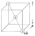
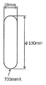
焼準後、棒鋼の中心部から、図1に示す形状の熱処理ひずみのバラツキ量測定用試験片を、各鋼について60個ずつ作製した。なお、いずれの鋼についても、棒鋼の軸方向と試験片の軸方向が同じ方向になるように試験片を採取した。 After normalization, 60 test pieces for measuring the amount of variation in heat treatment strain of the shape shown in FIG. 1 were produced for each steel from the center of the steel bar. In addition, about any steel, the test piece was extract | collected so that the axial direction of a steel bar and the axial direction of a test piece might become the same direction.
上記の試験片を用いて、浸炭焼入れ時の焼入れひずみバラツキ量を評価した。 The amount of quenching strain variation during carburizing and quenching was evaluated using the above test piece.
具体的には、各鋼毎に、図2に示す様に、熱処理バスケットの左上奥、中央、右下手前の3箇所に、あらかじめ図1のA部の間隔を浸炭焼入れ前にマイクロメータで測定した試験片を5個ずつ配置して、バッチ形のガス浸炭炉で浸炭焼入れした。焼入れ後は、焼戻しを行った。なお、図2中の「1」、「2」および「3」はそれぞれ、バスケット内に配置した位置の「左上奥」、「中央」および「右下手前」表す。 Specifically, for each steel, as shown in FIG. 2, the spacing of part A in FIG. 1 is measured in advance with a micrometer before carburizing and quenching at the upper left back, center, and lower right front of the heat treatment basket. Five test pieces were arranged and carburized and quenched in a batch-type gas carburizing furnace. After quenching, tempering was performed. Note that “1”, “2”, and “3” in FIG. 2 respectively represent “upper left rear”, “center”, and “lower right front” at positions arranged in the basket.
図3に、上記の「浸炭焼入れ−焼戻し」のヒートパターンを示す。なお、図3において、「Cp」は「炭素ポテンシャル」を表す。また、「OQ」は「油焼入れ」を表し、表2に示す[i]〜[iv]の条件の油を用いて行った。焼戻し後の冷却は大気中放冷とし、図3では「AC」と表記した。 In FIG. 3, the heat pattern of said "carburization hardening-tempering" is shown. In FIG. 3, “Cp” represents “carbon potential”. “OQ” represents “oil quenching”, and was performed using oils having the conditions [i] to [iv] shown in Table 2. Cooling after tempering was allowed to cool in the atmosphere, and was represented as “AC” in FIG.
各条件の油を用いて焼入れし、次いで焼戻しを行った後、A部の間隔をマイクロメータで測定し、「浸炭焼入れ−焼戻し」前後のA部の間隔差を求めた。熱処理バスケットの1〜3の位置に配置した各5個(合計15個)の試験片の前記A部間隔差の平均値をひずみ量とした。また、前記15個の試験片のA部間隔差の標準偏差を算出して、焼入れひずみバラツキを評価した。
After quenching using oil of each condition and then tempering, the interval between the A parts was measured with a micrometer, and the difference in the A part interval before and after “carburizing and quenching” was obtained. The average value of the A-part interval difference of each of five (total 15) test pieces arranged at
また、「浸炭焼入れ−焼戻し」後にA部の間隔をマイクロメータで測定した試験片のうちから、各条件について1個ずつ任意に選び、図1のB部を縦断して鏡面研磨した後、光学顕微鏡を使って、倍率1000倍でB部断面の外周側の表層部を観察し、さらに、ナイタールで腐食し、走査型電子顕微鏡(以下、「SEM」という。)を使って倍率3000倍で前記表層部を観察した。 Moreover, after “carburizing quenching and tempering”, one piece is arbitrarily selected for each condition from the test pieces measured with a micrometer at the interval of A part, and the B part in FIG. Using a microscope, observe the outer surface of the B section cross section at a magnification of 1000 times, further corrode with nital, and using a scanning electron microscope (hereinafter referred to as “SEM”) at a magnification of 3000 times. The surface layer was observed.
光学顕微鏡を使った倍率1000倍の観察では粒界酸化深さを測定した。また、SEMを使った倍率3000倍の観察では、特に粒界酸化物近傍の組織における不完全焼入れ組織の有無を調査した。 The grain boundary oxidation depth was measured in an observation with a magnification of 1000 times using an optical microscope. In addition, in the observation with a magnification of 3000 times using SEM, the presence or absence of an incompletely quenched structure particularly in the structure near the grain boundary oxide was investigated.
表3に、上記の試験結果を整理して示す。なお、表3において「ひずみ量」は1〜3の位置の各5個、合計15個のA部の間隔差の平均値を指す。また、「粒界酸化深さ」はB部で観察されたうち、最大の粒界酸化深さを指す。
Table 3 summarizes the above test results. In Table 3, “strain amount” refers to the average value of the interval difference of 15 parts A in total, 5 at each of
表3から、焼入れ油の条件[i]〜[iv]で、試験片A部の焼入れひずみバラツキに差は認められないものの、試験片B部のSEMを用いた観察結果には差があることが明らかである。 From Table 3, there is no difference in the quenching strain variation of the test piece A part under the quenching oil conditions [i] to [iv], but there is a difference in the observation results using the SEM of the test piece B part. Is clear.
先ず、不完全焼入れ組織については、次のとおりである。 First, the incompletely quenched structure is as follows.
NiおよびMoの含有量の高い鋼eは、焼入れ油の条件が[i]、[iii]および[iv]で、不完全焼入れ組織が認められなかった。また、鋼dは、焼入れ油の条件が[i]の場合のみ、不完全焼入れ組織が認められなかった。一方、鋼a〜cは、焼入れ油の条件が[i]〜[iv]の全てにおいて、不完全焼入れ組織が認められた。 Steel e with a high content of Ni and Mo had quenching oil conditions of [i], [iii] and [iv], and no incompletely quenched structure was observed. In steel d, an incompletely quenched structure was not observed only when the quenching oil condition was [i]. On the other hand, in steels a to c, an incompletely quenched structure was observed in all the conditions of the quenching oil [i] to [iv].
次に、粒界酸化深さについては、化学組成が本発明で規定する範囲内にある鋼dの場合、焼入れ油の条件に拘わらず4.7〜5.5μmと浅い。これに対して、化学組成が本発明で規定する条件から外れた比較例の鋼a〜cおよび鋼eの場合、粒界酸化深さは11.1μm以上と大きく、鋼dの場合に比べて劣っている。 Next, as for the grain boundary oxidation depth, in the case of steel d whose chemical composition is within the range defined in the present invention, it is shallow at 4.7 to 5.5 μm regardless of the conditions of the quenching oil. On the other hand, in the case of steels a to c and steel e of comparative examples whose chemical compositions deviate from the conditions specified in the present invention, the grain boundary oxidation depth is as large as 11.1 μm or more, compared with the case of steel d. Inferior.
すなわち、化学組成が本発明で規定する条件から外れた鋼a〜cの場合には、焼入れ油が本発明で規定する条件を満たす[i]の場合であっても、不完全焼入れ組織を抑制することができず、さらに粒界酸化深さも大きい。 That is, in the case of steels a to c whose chemical compositions deviate from the conditions specified in the present invention, even when the quenching oil satisfies the conditions specified in the present invention [i], the incompletely quenched structure is suppressed. In addition, the grain boundary oxidation depth is also large.
これに対して、化学組成が本発明で規定する範囲内にある鋼dの場合、本発明で規定する条件を満たす[i]の油を用いて焼入れすることで、高Ni−高Mo鋼である鋼eと同様に不完全焼入れ組織の生成を抑制することができ、しかも従来と同程度の熱処理ひずみバラツキとすることもできる。なお、鋼eの場合、粒界酸化深さが大きく、鋼dの場合に比べて劣っている。 On the other hand, in the case of steel d whose chemical composition is within the range specified by the present invention, by quenching with the oil of [i] that satisfies the conditions specified by the present invention, high Ni-high Mo steel is obtained. The formation of an incompletely hardened structure can be suppressed as in the case of a certain steel e, and the heat treatment strain variation can be made to the same extent as in the conventional case. In the case of steel e, the grain boundary oxidation depth is large, which is inferior to that of steel d.
(実施例2)
表4および表5に示す化学組成を有する鋼1〜31を180kg真空溶解炉で溶製した後、直径210mmの鋳型に鋳造してインゴットを得、室温まで冷却した。(Example 2)
なお、表4中の鋼1〜4、7、8、10〜13は、化学組成が本発明で規定する範囲内にある鋼であり、鋼5、6および9は参考例の鋼である。
一方、表4および表5中の鋼14〜31は、化学組成が本発明で規定する条件から外れた比較例の鋼である。なお、これら比較例の鋼のうちで鋼15はJIS G 4053(2008)に規定されたSCr420に相当する鋼である。 On the other hand, steels 14 to 31 in Tables 4 and 5 are steels of comparative examples whose chemical compositions deviate from the conditions defined in the present invention. Of these comparative steels, steel 15 is steel corresponding to SCr420 defined in JIS G 4053 (2008).
上記の鋼1〜31のインゴットは、1250℃で120min保持した後、熱間鍛造を行って、1000℃以上の温度で直径35mmの棒鋼に仕上げ、大気中で室温まで放冷した。
The ingots of the
上記の棒鋼には、925℃で60min保持してから、大気中で室温まで放冷する「焼準」を施した。 The above steel bars were subjected to “normalization” in which the steel bars were held at 925 ° C. for 60 minutes and then allowed to cool to room temperature in the atmosphere.
このようにして得た直径が35mmの焼準後の棒鋼の中心部から、直径が10mm、20mmおよび30mmで、長さがいずれも100mmの各丸棒を切り出した。 Each round bar having a diameter of 10 mm, 20 mm, and 30 mm and a length of 100 mm was cut out from the center part of the steel bar after the normalization having a diameter of 35 mm.
上記の直径が10mm、20mmおよび30mmで、長さが100mmに切り出した丸棒は、さらに925℃で60min保持した後、大気中で室温まで放冷する「焼準」を施した。なお、上記放冷時の800℃から500℃までの冷却速度は、0.8〜1.2℃/sであった。 The above-mentioned round bars having a diameter of 10 mm, 20 mm and 30 mm and cut to a length of 100 mm were further subjected to “normalization” which was kept at 925 ° C. for 60 minutes and then allowed to cool to room temperature in the atmosphere. In addition, the cooling rate from 800 degreeC to 500 degreeC at the time of the said cooling was 0.8-1.2 degreeC / s.
直径が10mm、20mmおよび30mmの焼準後の各丸棒を、長さ50mmの位置で横断して鏡面研磨し、それぞれ、中心から2.5mm、5mmおよび7.5mm位置のビッカース硬さを4点ずつ、JIS Z 2244(2009)に記載の「ビッカース硬さ試験−試験方法」に準拠して、ビッカース硬度計で測定した。なお、試験力は9.8Nとした。 Each round bar after normalization having a diameter of 10 mm, 20 mm, and 30 mm was mirror-polished across the position of 50 mm in length, and the Vickers hardness at 2.5 mm, 5 mm, and 7.5 mm position from the center was 4 respectively. Each point was measured with a Vickers hardness tester in accordance with “Vickers hardness test-test method” described in JIS Z 2244 (2009). The test force was 9.8N.
上記各4点のビッカース硬さ(以下「HV」という。)の平均値を、それぞれの直径の丸棒における焼準後のHVとした。なお、直径が10mm、20mmおよび30mmのいずれの場合にも、HVが192以下である場合に、硬さが低く被削性および冷間鍛造性に優れると評価した。 The average value of the above four Vickers hardnesses (hereinafter referred to as “HV”) was defined as the HV after normalization in the round bars having the respective diameters. In all cases where the diameter was 10 mm, 20 mm and 30 mm, when HV was 192 or less, it was evaluated that the hardness was low and the machinability and cold forgeability were excellent.
また、各鋼について、直径が35mmの焼準後の棒鋼の中心部から、いずれも軸方向に平行に、図4に示す形状の小野式回転曲げ疲労試験片を16本、図5に示す形状の4点曲げ疲労試験片を4本、図6に示す形状のローラピッチング小ローラ試験片を8本切り出した。 Further, for each steel, 16 pieces of Ono-type rotating bending fatigue test pieces having the shape shown in FIG. 4 are formed parallel to the axial direction from the center portion of the steel bar after the normalization having a diameter of 35 mm, and the shape shown in FIG. Four 4-point bending fatigue test pieces and eight roller pitching small roller test pieces having the shape shown in FIG. 6 were cut out.
上記の各試験片に対して、図3に示すヒートパターンで「浸炭焼入れ−焼戻し」を施した。なお、焼入れは、前記表2に示した[i]〜[iv]のいずれかの条件の油を用いて行った。 Each of the above test pieces was subjected to “carburizing and tempering” with the heat pattern shown in FIG. In addition, hardening was performed using the oil of the conditions in any one of [i]-[iv] shown in the said Table 2.
上記のようにして作製した各試験片は、小野式回転曲げ疲労試験、4点曲げ疲労試験、ローラピッチング試験およびSEMを使った表層部観察に供した。 Each test piece produced as described above was subjected to an ono-type rotary bending fatigue test, a four-point bending fatigue test, a roller pitching test, and surface layer observation using an SEM.
なお、後述の表6における試験符号Sでは、「浸炭焼入れ−焼戻し」を施した小野式回転曲げ疲労試験片および4点曲げ疲労試験片の切欠部を研磨した後、また、ローラピッチング小ローラ試験片の直径26mm部を研磨した後、直径が0.6mmでHVが800の鋼球を使って、アークハイト:0.4mmAおよびカバレージ:300%の条件でショットピーニングを施し、その後、小野式回転曲げ疲労試験、4点曲げ疲労試験、ローラピッチング試験およびSEMを使った表層部観察に供した。 Incidentally, in test code S in Table 6 described later, after polishing the notched portions of the Ono-type rotating bending fatigue test piece and the four-point bending fatigue test piece subjected to “carburization quenching and tempering”, the roller pitching small roller test is performed. After polishing the 26 mm diameter of the piece, shot peening was performed using a steel ball having a diameter of 0.6 mm and an HV of 800 under conditions of arc height: 0.4 mmA and coverage: 300%, and then ono type rotation. Bending fatigue test, 4-point bending fatigue test, roller pitching test and surface layer observation using SEM were used.
また、表6における試験符号Tでは、「浸炭焼入れ−焼戻し」を施した小野式回転曲げ疲労試験片および4点曲げ疲労試験片の切欠部、ローラピッチング小ローラ試験片の直径26mm部に対して、直径が0.6mmでHVが800の鋼球を使って、アークハイト:0.4mmAおよびカバレージ:300%の条件でショットピーニングを施し、その後さらに、小野式回転曲げ疲労試験片および4点曲げ疲労試験片の切欠部、ローラピッチング小ローラ試験片の直径26mm部を研磨して、小野式回転曲げ疲労試験、4点曲げ疲労試験、ローラピッチング試験およびSEMを使った表層部観察に供した。 Further, in test code T in Table 6, with respect to the notch portion of the Ono-type rotating bending fatigue test piece and the four-point bending fatigue test piece subjected to “carburizing quenching and tempering”, and the diameter of the roller pitching small roller test piece of 26 mm. Using a steel ball having a diameter of 0.6 mm and an HV of 800, shot peening was performed under conditions of arc height: 0.4 mmA and coverage: 300%, and then, further, an Ono-type rotary bending fatigue test piece and 4-point bending The notch portion of the fatigue test piece and the 26 mm diameter portion of the roller pitching small roller test piece were polished and subjected to an Ono-type rotary bending fatigue test, a 4-point bending fatigue test, a roller pitching test, and surface layer observation using an SEM.
なお、ローラピッチング試験に用いる図7に示す形状のローラピッチング大ローラ試験片は、JIS G 4052(2008)に規定されたSCM420Hを用いて、一般的な製造工程、つまり、「焼準、試験片加工、ガス浸炭炉による共析浸炭、低温焼戻しおよび研磨」の工程によって作製した。 Note that the roller pitching large roller test piece having the shape shown in FIG. 7 used for the roller pitching test is a general manufacturing process using SCM420H defined in JIS G 4052 (2008). It was produced by the steps of “processing, eutectoid carburizing by gas carburizing furnace, low temperature tempering and polishing”.
以下、各試験内容について詳しく説明する。 Hereinafter, each test content will be described in detail.
<A>SEMを使った表層部観察:
小野式回転曲げ疲労試験片の切欠部の横断面を鏡面研磨した後、光学顕微鏡を使って、倍率1000倍で表層部の観察を実施し、粒界酸化深さを測定した。さらに、ナイタールで腐食し、SEMを使って倍率3000倍で表層部を観察し、特に粒界酸化物近傍の組織における不完全焼入れ組織の有無を調査した。<A> Surface layer observation using SEM:
After the cross section of the notch portion of the Ono type rotating bending fatigue test piece was mirror-polished, the surface layer portion was observed at a magnification of 1000 times using an optical microscope, and the grain boundary oxidation depth was measured. Furthermore, it corroded with nital, the surface layer part was observed at 3000 times magnification using SEM, and the presence or absence of an incompletely quenched structure particularly in the structure near the grain boundary oxide was investigated.
なお、表層部に不完全焼入れ組織が存在しないことを目標とした。 The target was that there was no incompletely quenched structure in the surface layer.
<B>小野式回転曲げ疲労試験:
小野式回転曲げ疲労試験片を8本用いて、下記の試験条件によって小野式回転曲げ疲労試験を実施し、繰返し数が1.0×10⁷回において破断しない最大の強度で「高サイクル曲げ疲労強度」を評価した。<B> Ono type rotating bending fatigue test:
Ono type rotating bending fatigue test piece by using eight, conducted Ono type rotating bending fatigue test by the test conditions below, "high cycle with maximum intensity that does not break the repetition number is 1.0 × 10 7 times bending fatigue Strength was evaluated.
試験結果は、JIS G 4053(2008)に規定されたSCr420の相当する鋼15を用いた表6における試験符号Vの1.0×10⁷回の回転曲げ疲労強度を100として基準化した。そして、回転曲げ疲労強度が評価基準の1.15倍を超える、すなわち115を超えるものを高サイクル曲げ疲労強度に優れるとした。The test results were standardized with 100 × 10 7 rotation bending fatigue strength of test code V in Table 6 using steel 15 corresponding to SCr420 defined in JIS G 4053 (2008) as 100. And the thing whose rotation bending fatigue strength exceeds 1.15 times of evaluation criteria, ie, exceeds 115, was considered to be excellent in high cycle bending fatigue strength.
・温度:室温、
・雰囲気:大気中、
・回転数:3000rpm。・ Temperature: Room temperature,
・ Atmosphere: In air
-Number of rotations: 3000 rpm.
<C>4点曲げ疲労試験:
4点曲げ疲労試験片を2本用いて、図8に示す方法で、4点曲げ疲労試験を実施した。試験荷重は最大荷重を10kN、最小荷重を1kNとし、繰返し数20Hzで破断するまでの繰返し数を調査して、「低サイクル曲げ疲労強度」を評価した。<C> Four-point bending fatigue test:
A four-point bending fatigue test was performed using two four-point bending fatigue test pieces by the method shown in FIG. With regard to the test load, the maximum load was 10 kN, the minimum load was 1 kN, the number of repetitions until breaking at a repetition rate of 20 Hz was investigated, and “low cycle bending fatigue strength” was evaluated.
試験結果は、上記のSCr420の相当する鋼15を用いた試験符号Vの破断寿命を100として基準化した。そして、破断寿命が評価基準の2倍以上、すなわち200以上となるものを低サイクル疲労強度に優れるとした。 The test results were normalized with the rupture life of test code V using steel 15 corresponding to the above-mentioned SCr420 as 100. And the thing whose fracture life becomes 2 times or more of the evaluation criteria, that is, 200 or more, is excellent in low cycle fatigue strength.
<D>ローラピッチング試験:
ローラピッチング試験は、図9に示すように、図6に示す形状のローラピッチング小ローラ試験片と図7に示す形状のローラピッチング大ローラの組み合わせで、下記に示す条件で行った。<D> Roller pitching test:
As shown in FIG. 9, the roller pitching test was performed under the conditions shown below using a combination of a roller pitching small roller test piece having the shape shown in FIG. 6 and a roller pitching large roller having the shape shown in FIG.
ローラピッチング試験における試験数は6とし、縦軸に面圧、横軸にピッチング発生までの繰り返し数をとったS−N線図を作成し、繰り返し数2.0×10⁷回までピッチングが発生しなかったうちで、最も高い面圧を「耐ピッチング強度」とした。The number of tests in the roller pitching test is 6, and an SN diagram is created with the vertical axis representing the surface pressure and the horizontal axis representing the number of repetitions until the occurrence of pitching. Pitching occurs up to 2.0 × 10 7 repetitions. Among them, the highest surface pressure was defined as “pitting resistance”.
なお、ローラピッチング小ローラの試験部の表面が損傷している箇所のうち、最大のものの面積が1mm2以上になった場合をピッチング発生とした。Of the portions where the surface of the test part of the roller pitching small roller is damaged, the case where the area of the largest one is 1 mm 2 or more is defined as the occurrence of pitching.
試験結果は、上記のSCr420の相当する鋼15を用いた試験符号Vの耐ピッチング強度を100として基準化した。そして、耐ピッチング強度が評価基準の1.20倍以上、すなわち120以上となるものを耐ピッチング強度に優れるとした。 The test results were standardized with the pitching strength of test code V using steel 15 corresponding to the above-mentioned SCr420 as 100. And it was supposed that the pitching strength was 1.20 times or more of the evaluation standard, that is, 120 or more, excellent in the pitching strength.
・すべり率:−40%、
・面圧:1600〜3000MPa、
・小ローラー試験片の回転数:1500rpm、
・周速:大ローラー試験片の周速V1:2.86m/s、
小ローラー試験片の周速V2:2.04m/s、
・潤滑油:種類:オートマチックトランスミッション油、
油温:90℃、
油量:1.0L/min。・ Slip rate: -40%,
-Surface pressure: 1600-3000 MPa,
-Number of rotations of small roller test piece: 1500 rpm,
・ Peripheral speed: Large roller test piece peripheral speed V1: 2.86 m / s,
Small roller test piece peripheral speed V2: 2.04 m / s,
・ Lubricant: Type: Automatic transmission oil,
Oil temperature: 90 ° C
Oil amount: 1.0 L / min.
なお、潤滑は、上記潤滑油をローラーピッチング小ローラー試験片とローラーピッチング大ローラー試験片の接触部に噴出させて実施した。 The lubrication was performed by jetting the lubricating oil onto the contact portion between the roller pitching small roller test piece and the roller pitching large roller test piece.
上記の「すべり率」は、下記の式で計算される値を指す。
{(V2−V1)/V2}×100。The above “slip rate” refers to a value calculated by the following formula.
{(V2-V1) / V2} × 100.
表6に、上記の各試験結果をまとめて示す。なお、表6中の「焼準後のHV」欄には、各試験符号について直径が10mm、20mmおよび30mmの丸棒について測定したHVのうちの最高の値を示す。 Table 6 summarizes the test results described above. In addition, in the “HV after normalization” column in Table 6, the highest value of HV measured for round bars having diameters of 10 mm, 20 mm, and 30 mm for each test code is shown.
表6から、本発明で規定する条件を満たす本発明例の試験符号の場合には、目標とする硬さ、表層部組織、高サイクル曲げ疲労強度、低サイクル曲げ疲労強度および耐ピッチング疲労強度の全てが得られていることが明らかである。 From Table 6, in the case of the test code of the present invention example that satisfies the conditions specified in the present invention, the target hardness, surface layer structure, high cycle bending fatigue strength, low cycle bending fatigue strength and pitting fatigue resistance It is clear that everything has been obtained.
これに対して、本発明で規定する条件から外れた比較例の試験符号の場合には、目標とする硬さ、表層部組織、高サイクル曲げ疲労強度、低サイクル曲げ疲労強度および耐ピッチング疲労強度のうちの1つ以上の特性が得られていない。 On the other hand, in the case of a test code of a comparative example that deviates from the conditions specified in the present invention, the target hardness, surface layer structure, high cycle bending fatigue strength, low cycle bending fatigue strength and pitting fatigue resistance One or more of the characteristics are not obtained.
試験符号A〜Eの場合、用いた鋼7、鋼10および鋼12の化学組成はいずれも本発明で規定する範囲内にあるが、焼入れ油の条件が本発明で規定する条件から外れており、このため、表層部組織、高サイクル曲げ疲労強度、低サイクル曲げ疲労強度および耐ピッチング疲労強度が目標に達していない。 In the case of test codes A to E, the chemical compositions of Steel 7, Steel 10 and Steel 12 used are all within the range defined by the present invention, but the quenching oil conditions are not within the conditions defined by the present invention. For this reason, the surface layer structure, the high cycle bending fatigue strength, the low cycle bending fatigue strength and the pitting fatigue strength have not reached the targets.
また、試験符号U〜Zおよび試験符号AA〜ALの場合、焼入れ油の条件は本発明で規定する範囲内にあるものの、用いた鋼14〜31の化学組成がいずれも、本発明で規定する条件から外れている。このため、硬さ、表層部組織、高サイクル曲げ疲労強度、低サイクル曲げ疲労強度および耐ピッチング疲労強度のうちの1つ以上の特性が目標に達していない。 Moreover, in the case of test code | symbol UZ and test code | symbol AA-AL, although the conditions of quenching oil exist in the range prescribed | regulated by this invention, all the chemical compositions of the used steel 14-31 prescribe | regulate by this invention. Out of condition. For this reason, one or more characteristics of hardness, surface layer structure, high cycle bending fatigue strength, low cycle bending fatigue strength, and pitting fatigue strength have not reached the target.
本発明によって、高価な合金元素の含有量が少ないにも拘わらず、優れた、高サイクル曲げ疲労強度、低サイクル曲げ疲労強度および耐ピッチング強度を有し、しかも、製造時の切削加工工程においては十分な被削性を、あるいは、ネットシェイプ成形工程においては十分な冷間鍛造性を、確保できるとともに、浸炭焼入れまたは浸炭窒化焼入れ時の熱処理ひずみのバラツキが抑制された鋼製部品が得られる。
According to the present invention, despite having a low content of expensive alloy elements, it has excellent high cycle bending fatigue strength, low cycle bending fatigue strength and anti-pitting strength, and in the cutting process during production. Sufficient machinability or sufficient cold forgeability in the net shape forming process can be ensured, and a steel part in which variation in heat treatment strain during carburizing or carbonitriding and quenching is suppressed can be obtained.
Claims (3)
C:0.15〜0.25%、
Si:0.01〜0.10%、
Mn:0.55〜0.80%、
S:0.003〜0.030%、
Cr:0.80〜1.18%、
Mo:0.30〜0.45%、
Al:0.015〜0.050%および
N:0.010〜0.025%
を含有するとともに、
下記の(1)式で表されるfnが1.3〜2.4であり、
残部がFeおよび不純物からなり、不純物中のPおよびOがそれぞれ、
P:0.010%以下および
O:0.0020%以下
である鋼材に次のステップ1およびステップ2の処理を順に施すことを特徴とする、
鋼製部品の製造方法。
ステップ1:温度が850〜1000℃の浸炭雰囲気または浸炭窒化雰囲気に2〜15h保持して、浸炭または浸炭窒化を施す処理。
ステップ2:当該浸炭または浸炭窒化が施された鋼材に、温度が40〜80℃で、かつ40℃における動粘度が20〜25mm2/sである焼入れ油を用いて焼入れを行う処理。
fn=Cr/Mn・・・(1)
ただし、(1)式におけるCrおよびMnは、その元素の質量%での含有量を表す。 % By mass
C: 0.15-0.25%,
Si: 0.01 to 0.10%,
Mn: 0.55 to 0.80%,
S: 0.003-0.030%,
Cr: 0.80 to 1.18 %,
Mo: 0.30 to 0.45%,
Al: 0.015-0.050% and N: 0.010-0.025%
And containing
Fn represented by the following formula (1) is 1.3 to 2.4,
The balance consists of Fe and impurities, and P and O in the impurities are respectively
P: 0.010% or less and O: 0.0020% or less, characterized in that the following step 1 and step 2 are sequentially processed,
Manufacturing method for steel parts.
Step 1: A process of carburizing or carbonitriding by holding in a carburizing atmosphere or carbonitriding atmosphere at a temperature of 850 to 1000 ° C. for 2 to 15 hours .
Step 2: A process for quenching the carburized or carbonitrided steel using a quenching oil having a temperature of 40 to 80 ° C. and a kinematic viscosity at 40 ° C. of 20 to 25 mm 2 / s.
fn = Cr / Mn (1)
However, Cr and Mn in the formula (1) represent the content in mass% of the element.
請求項1に記載の鋼製部品の製造方法。 The carburizing or carbonitriding treatment in step 1 consists of holding in a carburizing atmosphere or carbonitriding atmosphere at a temperature of 850 to 1000 ° C. and subsequent holding in a carburizing atmosphere or carbonitriding atmosphere at a temperature of 800 to 900 ° C. It is characterized by
The manufacturing method of the steel components of Claim 1.
Nb:0.08%以下
を含有する、
請求項1または2に記載の鋼製部品の製造方法。 Steel material, instead of a part of Fe, in mass%,
Nb: 0.08% or less,
The manufacturing method of the steel components of Claim 1 or 2.
Priority Applications (1)
| Application Number | Priority Date | Filing Date | Title |
|---|---|---|---|
| JP2013541806A JP5824063B2 (en) | 2011-11-01 | 2012-10-31 | Manufacturing method of steel parts |
Applications Claiming Priority (4)
| Application Number | Priority Date | Filing Date | Title |
|---|---|---|---|
| JP2011240003 | 2011-11-01 | ||
| JP2011240003 | 2011-11-01 | ||
| PCT/JP2012/078125 WO2013065718A1 (en) | 2011-11-01 | 2012-10-31 | Method for producing steel part |
| JP2013541806A JP5824063B2 (en) | 2011-11-01 | 2012-10-31 | Manufacturing method of steel parts |
Publications (2)
| Publication Number | Publication Date |
|---|---|
| JPWO2013065718A1 JPWO2013065718A1 (en) | 2015-04-02 |
| JP5824063B2 true JP5824063B2 (en) | 2015-11-25 |
Family
ID=48192063
Family Applications (1)
| Application Number | Title | Priority Date | Filing Date |
|---|---|---|---|
| JP2013541806A Active JP5824063B2 (en) | 2011-11-01 | 2012-10-31 | Manufacturing method of steel parts |
Country Status (5)
| Country | Link |
|---|---|
| US (1) | US9410232B2 (en) |
| JP (1) | JP5824063B2 (en) |
| CN (1) | CN104024444B (en) |
| IN (1) | IN2014DN03964A (en) |
| WO (1) | WO2013065718A1 (en) |
Families Citing this family (9)
| Publication number | Priority date | Publication date | Assignee | Title |
|---|---|---|---|---|
| US8923426B2 (en) * | 2012-10-23 | 2014-12-30 | Qualcomm Incorporated | Methods and apparatus for managing wireless medium utilization |
| DE102013226090A1 (en) * | 2013-12-16 | 2015-06-18 | Robert Bosch Gmbh | Process for gas nitrocarburizing |
| CN105177231B (en) * | 2015-10-21 | 2017-07-28 | 江苏华久辐条制造有限公司 | A kind of Technology for Heating Processing of spoke bar cap quick-turning steel |
| DE102015224644A1 (en) * | 2015-12-09 | 2017-06-14 | Zf Friedrichshafen Ag | Shot blasted tooth flanks |
| CN106222605A (en) * | 2016-08-29 | 2016-12-14 | 盐城圣奥热处理有限公司 | A kind of gear carburizing quenching process |
| CN106835004A (en) * | 2017-01-14 | 2017-06-13 | 山东海利传动机械制造有限公司 | A kind of gear shaft composite step carburizing quenching process |
| CN110373607B (en) * | 2019-07-25 | 2021-04-02 | 广东韶钢松山股份有限公司 | High-temperature carburized steel, high-temperature carburized steel component and preparation method thereof |
| KR20220040153A (en) * | 2020-09-23 | 2022-03-30 | 현대자동차주식회사 | Carburizing steel improved durability |
| CN113667901A (en) * | 2021-08-23 | 2021-11-19 | 智奇铁路设备有限公司 | Material for locomotive wheels |
Family Cites Families (13)
| Publication number | Priority date | Publication date | Assignee | Title |
|---|---|---|---|---|
| JPS6021359A (en) | 1983-07-15 | 1985-02-02 | Daido Steel Co Ltd | Steel for gear |
| JPH07109005B2 (en) | 1987-07-28 | 1995-11-22 | マツダ株式会社 | Method for manufacturing heat-treated steel parts |
| JP3240627B2 (en) * | 1991-03-27 | 2001-12-17 | 日産自動車株式会社 | Manufacturing method of constant velocity joint parts |
| JPH06271983A (en) | 1993-03-18 | 1994-09-27 | Kobe Steel Ltd | High strength piston pin excellent in formability and bending strength |
| JP3118346B2 (en) | 1993-04-20 | 2000-12-18 | 大同特殊鋼株式会社 | Tooth wheel |
| JPH07126803A (en) | 1993-11-08 | 1995-05-16 | Daido Steel Co Ltd | Steel for carburizing gear |
| JP3308377B2 (en) | 1994-03-09 | 2002-07-29 | 大同特殊鋼株式会社 | Gear with excellent tooth surface strength and method of manufacturing the same |
| JP4101321B2 (en) | 1996-12-02 | 2008-06-18 | 新日本石油株式会社 | Heat treated oil |
| JP4659264B2 (en) | 2001-05-02 | 2011-03-30 | 出光興産株式会社 | Heat treated oil composition |
| JP4243852B2 (en) | 2004-06-03 | 2009-03-25 | 住友金属工業株式会社 | Steel for carburized parts or carbonitrided parts, method for producing carburized parts or carbonitrided parts |
| EP2039746B1 (en) | 2006-07-06 | 2013-10-09 | Nippon Oil Corporation | Refrigerator oil composition |
| JP5503170B2 (en) | 2009-03-23 | 2014-05-28 | 株式会社神戸製鋼所 | Case-hardened steel with excellent maximum grain reduction characteristics |
| US8475605B2 (en) * | 2010-03-19 | 2013-07-02 | Nippon Steel & Sumitomo Metal Corporation | Surface layer-hardened steel part and method of manufacturing the same |
-
2012
- 2012-10-31 WO PCT/JP2012/078125 patent/WO2013065718A1/en active Application Filing
- 2012-10-31 JP JP2013541806A patent/JP5824063B2/en active Active
- 2012-10-31 IN IN3964DEN2014 patent/IN2014DN03964A/en unknown
- 2012-10-31 CN CN201280065772.2A patent/CN104024444B/en active Active
- 2012-10-31 US US14/352,829 patent/US9410232B2/en active Active
Also Published As
| Publication number | Publication date |
|---|---|
| US9410232B2 (en) | 2016-08-09 |
| JPWO2013065718A1 (en) | 2015-04-02 |
| WO2013065718A1 (en) | 2013-05-10 |
| CN104024444A (en) | 2014-09-03 |
| IN2014DN03964A (en) | 2015-05-15 |
| CN104024444B (en) | 2016-10-26 |
| US20140246126A1 (en) | 2014-09-04 |
Similar Documents
| Publication | Publication Date | Title |
|---|---|---|
| JP5824063B2 (en) | Manufacturing method of steel parts | |
| JP5126857B2 (en) | Manufacturing method of case-hardened steel pipe with excellent workability | |
| JP5332646B2 (en) | Manufacturing method of carburizing steel with excellent cold forgeability | |
| JP5927868B2 (en) | Carburizing steel excellent in cold forgeability and method for producing the same | |
| JP4872846B2 (en) | Rough shape for nitriding gear and nitriding gear | |
| JP5333682B2 (en) | Rolled steel bar or wire rod for hot forging | |
| JP5660259B2 (en) | Carburized parts | |
| JP6073167B2 (en) | Case-hardening steel with excellent surface fatigue strength and cold forgeability | |
| JP5886119B2 (en) | Case-hardened steel | |
| JP2010150566A (en) | Steel for vacuum carburizing or vacuum carbo-nitriding | |
| JP5258458B2 (en) | Gears with excellent surface pressure resistance | |
| JP5683348B2 (en) | Carburized member, steel for carburized member, and method for manufacturing carburized member | |
| JP6414385B2 (en) | Carburized parts | |
| JP6447064B2 (en) | Steel parts | |
| JP7436779B2 (en) | Steel for carburized gears, carburized gears, and method for manufacturing carburized gears | |
| JP2022170056A (en) | steel | |
| JP4411096B2 (en) | Steel wire rod and steel bar for case hardening with excellent cold forgeability after spheronization | |
| JP4821582B2 (en) | Steel for vacuum carburized gear | |
| JP7323850B2 (en) | Steel and carburized steel parts | |
| JP7111029B2 (en) | Method for manufacturing steel parts | |
| JP7368697B2 (en) | Steel for carburized gears, carburized gears, and method for manufacturing carburized gears | |
| JP2009270160A (en) | Method for producing steel material for soft-nitriding | |
| WO2016158611A1 (en) | Steel for carburizing and carburized component |
Legal Events
| Date | Code | Title | Description |
|---|---|---|---|
| A131 | Notification of reasons for refusal |
Free format text: JAPANESE INTERMEDIATE CODE: A131 Effective date: 20150602 |
|
| A521 | Request for written amendment filed |
Free format text: JAPANESE INTERMEDIATE CODE: A523 Effective date: 20150731 |
|
| RD02 | Notification of acceptance of power of attorney |
Free format text: JAPANESE INTERMEDIATE CODE: A7422 Effective date: 20150731 |
|
| A521 | Request for written amendment filed |
Free format text: JAPANESE INTERMEDIATE CODE: A821 Effective date: 20150731 |
|
| TRDD | Decision of grant or rejection written | ||
| A01 | Written decision to grant a patent or to grant a registration (utility model) |
Free format text: JAPANESE INTERMEDIATE CODE: A01 Effective date: 20150915 |
|
| A61 | First payment of annual fees (during grant procedure) |
Free format text: JAPANESE INTERMEDIATE CODE: A61 Effective date: 20151008 |
|
| R150 | Certificate of patent or registration of utility model |
Ref document number: 5824063 Country of ref document: JP Free format text: JAPANESE INTERMEDIATE CODE: R150 |
|
| R250 | Receipt of annual fees |
Free format text: JAPANESE INTERMEDIATE CODE: R250 |
|
| S533 | Written request for registration of change of name |
Free format text: JAPANESE INTERMEDIATE CODE: R313533 |
|
| R350 | Written notification of registration of transfer |
Free format text: JAPANESE INTERMEDIATE CODE: R350 |
|
| R250 | Receipt of annual fees |
Free format text: JAPANESE INTERMEDIATE CODE: R250 |
|
| R250 | Receipt of annual fees |
Free format text: JAPANESE INTERMEDIATE CODE: R250 |
|
| R250 | Receipt of annual fees |
Free format text: JAPANESE INTERMEDIATE CODE: R250 |
|
| R250 | Receipt of annual fees |
Free format text: JAPANESE INTERMEDIATE CODE: R250 |
|
| R250 | Receipt of annual fees |
Free format text: JAPANESE INTERMEDIATE CODE: R250 |