JP5823864B2 - Medical ventilator volume control - Google Patents
Medical ventilator volume control Download PDFInfo
- Publication number
- JP5823864B2 JP5823864B2 JP2011531605A JP2011531605A JP5823864B2 JP 5823864 B2 JP5823864 B2 JP 5823864B2 JP 2011531605 A JP2011531605 A JP 2011531605A JP 2011531605 A JP2011531605 A JP 2011531605A JP 5823864 B2 JP5823864 B2 JP 5823864B2
- Authority
- JP
- Japan
- Prior art keywords
- ventilator
- patient
- housing
- flow
- battery pack
- Prior art date
- Legal status (The legal status is an assumption and is not a legal conclusion. Google has not performed a legal analysis and makes no representation as to the accuracy of the status listed.)
- Active
Links
- 238000009423 ventilation Methods 0.000 claims description 64
- 230000007246 mechanism Effects 0.000 claims description 34
- 238000000034 method Methods 0.000 claims description 28
- 238000002560 therapeutic procedure Methods 0.000 claims description 25
- 230000003434 inspiratory effect Effects 0.000 claims description 17
- 239000002253 acid Substances 0.000 claims description 13
- CURLTUGMZLYLDI-UHFFFAOYSA-N Carbon dioxide Chemical compound O=C=O CURLTUGMZLYLDI-UHFFFAOYSA-N 0.000 claims description 12
- 238000004891 communication Methods 0.000 claims description 10
- 239000012530 fluid Substances 0.000 claims description 10
- 230000004044 response Effects 0.000 claims description 7
- 229910002092 carbon dioxide Inorganic materials 0.000 claims description 6
- 239000001569 carbon dioxide Substances 0.000 claims description 6
- 238000003860 storage Methods 0.000 claims description 5
- 238000007599 discharging Methods 0.000 claims description 4
- 239000007789 gas Substances 0.000 description 68
- 239000000523 sample Substances 0.000 description 42
- CNQCVBJFEGMYDW-UHFFFAOYSA-N lawrencium atom Chemical compound [Lr] CNQCVBJFEGMYDW-UHFFFAOYSA-N 0.000 description 35
- 239000003570 air Substances 0.000 description 19
- QVGXLLKOCUKJST-UHFFFAOYSA-N atomic oxygen Chemical compound [O] QVGXLLKOCUKJST-UHFFFAOYSA-N 0.000 description 12
- 239000001301 oxygen Substances 0.000 description 12
- 229910052760 oxygen Inorganic materials 0.000 description 12
- 238000001914 filtration Methods 0.000 description 11
- 238000010586 diagram Methods 0.000 description 7
- 230000008901 benefit Effects 0.000 description 6
- 210000002445 nipple Anatomy 0.000 description 6
- 238000013461 design Methods 0.000 description 5
- HBBGRARXTFLTSG-UHFFFAOYSA-N Lithium ion Chemical compound [Li+] HBBGRARXTFLTSG-UHFFFAOYSA-N 0.000 description 4
- 201000010099 disease Diseases 0.000 description 4
- 208000037265 diseases, disorders, signs and symptoms Diseases 0.000 description 4
- 229910001416 lithium ion Inorganic materials 0.000 description 4
- 239000000463 material Substances 0.000 description 4
- 230000008569 process Effects 0.000 description 4
- 230000009977 dual effect Effects 0.000 description 3
- 239000006260 foam Substances 0.000 description 3
- 230000029058 respiratory gaseous exchange Effects 0.000 description 3
- 230000000153 supplemental effect Effects 0.000 description 3
- 241000894006 Bacteria Species 0.000 description 2
- 239000012080 ambient air Substances 0.000 description 2
- 238000001514 detection method Methods 0.000 description 2
- 238000004519 manufacturing process Methods 0.000 description 2
- 230000002093 peripheral effect Effects 0.000 description 2
- 230000003068 static effect Effects 0.000 description 2
- 238000004659 sterilization and disinfection Methods 0.000 description 2
- 238000012546 transfer Methods 0.000 description 2
- 230000007704 transition Effects 0.000 description 2
- 241001631457 Cannula Species 0.000 description 1
- OKTJSMMVPCPJKN-UHFFFAOYSA-N Carbon Chemical compound [C] OKTJSMMVPCPJKN-UHFFFAOYSA-N 0.000 description 1
- 230000003466 anti-cipated effect Effects 0.000 description 1
- -1 but not limited to Substances 0.000 description 1
- 229910052799 carbon Inorganic materials 0.000 description 1
- 230000008859 change Effects 0.000 description 1
- 238000006243 chemical reaction Methods 0.000 description 1
- 230000007812 deficiency Effects 0.000 description 1
- 230000000994 depressogenic effect Effects 0.000 description 1
- 238000009826 distribution Methods 0.000 description 1
- 229920001971 elastomer Polymers 0.000 description 1
- 238000003780 insertion Methods 0.000 description 1
- 230000037431 insertion Effects 0.000 description 1
- 238000009434 installation Methods 0.000 description 1
- 239000000203 mixture Substances 0.000 description 1
- 238000012986 modification Methods 0.000 description 1
- 230000004048 modification Effects 0.000 description 1
- 239000002991 molded plastic Substances 0.000 description 1
- 230000000474 nursing effect Effects 0.000 description 1
- 238000012913 prioritisation Methods 0.000 description 1
- 230000000135 prohibitive effect Effects 0.000 description 1
- 230000000241 respiratory effect Effects 0.000 description 1
- 210000002345 respiratory system Anatomy 0.000 description 1
- 229920002379 silicone rubber Polymers 0.000 description 1
- 239000004945 silicone rubber Substances 0.000 description 1
- 230000002269 spontaneous effect Effects 0.000 description 1
- 230000001954 sterilising effect Effects 0.000 description 1
- 238000012414 sterilization procedure Methods 0.000 description 1
- 238000012360 testing method Methods 0.000 description 1
- 230000002747 voluntary effect Effects 0.000 description 1
Images


Classifications
-
- A—HUMAN NECESSITIES
- A61—MEDICAL OR VETERINARY SCIENCE; HYGIENE
- A61M—DEVICES FOR INTRODUCING MEDIA INTO, OR ONTO, THE BODY; DEVICES FOR TRANSDUCING BODY MEDIA OR FOR TAKING MEDIA FROM THE BODY; DEVICES FOR PRODUCING OR ENDING SLEEP OR STUPOR
- A61M16/00—Devices for influencing the respiratory system of patients by gas treatment, e.g. mouth-to-mouth respiration; Tracheal tubes
- A61M16/20—Valves specially adapted to medical respiratory devices
- A61M16/201—Controlled valves
- A61M16/202—Controlled valves electrically actuated
- A61M16/203—Proportional
- A61M16/205—Proportional used for exhalation control
-
- A—HUMAN NECESSITIES
- A61—MEDICAL OR VETERINARY SCIENCE; HYGIENE
- A61M—DEVICES FOR INTRODUCING MEDIA INTO, OR ONTO, THE BODY; DEVICES FOR TRANSDUCING BODY MEDIA OR FOR TAKING MEDIA FROM THE BODY; DEVICES FOR PRODUCING OR ENDING SLEEP OR STUPOR
- A61M16/00—Devices for influencing the respiratory system of patients by gas treatment, e.g. mouth-to-mouth respiration; Tracheal tubes
- A61M16/0057—Pumps therefor
- A61M16/0066—Blowers or centrifugal pumps
- A61M16/0069—Blowers or centrifugal pumps the speed thereof being controlled by respiratory parameters, e.g. by inhalation
-
- A—HUMAN NECESSITIES
- A61—MEDICAL OR VETERINARY SCIENCE; HYGIENE
- A61M—DEVICES FOR INTRODUCING MEDIA INTO, OR ONTO, THE BODY; DEVICES FOR TRANSDUCING BODY MEDIA OR FOR TAKING MEDIA FROM THE BODY; DEVICES FOR PRODUCING OR ENDING SLEEP OR STUPOR
- A61M16/00—Devices for influencing the respiratory system of patients by gas treatment, e.g. mouth-to-mouth respiration; Tracheal tubes
- A61M16/021—Devices for influencing the respiratory system of patients by gas treatment, e.g. mouth-to-mouth respiration; Tracheal tubes operated by electrical means
- A61M16/022—Control means therefor
- A61M16/024—Control means therefor including calculation means, e.g. using a processor
-
- A—HUMAN NECESSITIES
- A61—MEDICAL OR VETERINARY SCIENCE; HYGIENE
- A61M—DEVICES FOR INTRODUCING MEDIA INTO, OR ONTO, THE BODY; DEVICES FOR TRANSDUCING BODY MEDIA OR FOR TAKING MEDIA FROM THE BODY; DEVICES FOR PRODUCING OR ENDING SLEEP OR STUPOR
- A61M16/00—Devices for influencing the respiratory system of patients by gas treatment, e.g. mouth-to-mouth respiration; Tracheal tubes
- A61M16/08—Bellows; Connecting tubes ; Water traps; Patient circuits
- A61M16/0816—Joints or connectors
- A61M16/0841—Joints or connectors for sampling
-
- A—HUMAN NECESSITIES
- A61—MEDICAL OR VETERINARY SCIENCE; HYGIENE
- A61M—DEVICES FOR INTRODUCING MEDIA INTO, OR ONTO, THE BODY; DEVICES FOR TRANSDUCING BODY MEDIA OR FOR TAKING MEDIA FROM THE BODY; DEVICES FOR PRODUCING OR ENDING SLEEP OR STUPOR
- A61M16/00—Devices for influencing the respiratory system of patients by gas treatment, e.g. mouth-to-mouth respiration; Tracheal tubes
- A61M16/08—Bellows; Connecting tubes ; Water traps; Patient circuits
-
- A—HUMAN NECESSITIES
- A61—MEDICAL OR VETERINARY SCIENCE; HYGIENE
- A61M—DEVICES FOR INTRODUCING MEDIA INTO, OR ONTO, THE BODY; DEVICES FOR TRANSDUCING BODY MEDIA OR FOR TAKING MEDIA FROM THE BODY; DEVICES FOR PRODUCING OR ENDING SLEEP OR STUPOR
- A61M16/00—Devices for influencing the respiratory system of patients by gas treatment, e.g. mouth-to-mouth respiration; Tracheal tubes
- A61M16/10—Preparation of respiratory gases or vapours
- A61M16/105—Filters
- A61M16/106—Filters in a path
- A61M16/107—Filters in a path in the inspiratory path
-
- A—HUMAN NECESSITIES
- A61—MEDICAL OR VETERINARY SCIENCE; HYGIENE
- A61M—DEVICES FOR INTRODUCING MEDIA INTO, OR ONTO, THE BODY; DEVICES FOR TRANSDUCING BODY MEDIA OR FOR TAKING MEDIA FROM THE BODY; DEVICES FOR PRODUCING OR ENDING SLEEP OR STUPOR
- A61M16/00—Devices for influencing the respiratory system of patients by gas treatment, e.g. mouth-to-mouth respiration; Tracheal tubes
- A61M16/20—Valves specially adapted to medical respiratory devices
- A61M16/208—Non-controlled one-way valves, e.g. exhalation, check, pop-off non-rebreathing valves
-
- A—HUMAN NECESSITIES
- A61—MEDICAL OR VETERINARY SCIENCE; HYGIENE
- A61M—DEVICES FOR INTRODUCING MEDIA INTO, OR ONTO, THE BODY; DEVICES FOR TRANSDUCING BODY MEDIA OR FOR TAKING MEDIA FROM THE BODY; DEVICES FOR PRODUCING OR ENDING SLEEP OR STUPOR
- A61M16/00—Devices for influencing the respiratory system of patients by gas treatment, e.g. mouth-to-mouth respiration; Tracheal tubes
- A61M16/0003—Accessories therefor, e.g. sensors, vibrators, negative pressure
- A61M2016/0027—Accessories therefor, e.g. sensors, vibrators, negative pressure pressure meter
-
- A—HUMAN NECESSITIES
- A61—MEDICAL OR VETERINARY SCIENCE; HYGIENE
- A61M—DEVICES FOR INTRODUCING MEDIA INTO, OR ONTO, THE BODY; DEVICES FOR TRANSDUCING BODY MEDIA OR FOR TAKING MEDIA FROM THE BODY; DEVICES FOR PRODUCING OR ENDING SLEEP OR STUPOR
- A61M16/00—Devices for influencing the respiratory system of patients by gas treatment, e.g. mouth-to-mouth respiration; Tracheal tubes
- A61M16/0003—Accessories therefor, e.g. sensors, vibrators, negative pressure
- A61M2016/003—Accessories therefor, e.g. sensors, vibrators, negative pressure with a flowmeter
- A61M2016/0033—Accessories therefor, e.g. sensors, vibrators, negative pressure with a flowmeter electrical
- A61M2016/0039—Accessories therefor, e.g. sensors, vibrators, negative pressure with a flowmeter electrical in the inspiratory circuit
-
- A—HUMAN NECESSITIES
- A61—MEDICAL OR VETERINARY SCIENCE; HYGIENE
- A61M—DEVICES FOR INTRODUCING MEDIA INTO, OR ONTO, THE BODY; DEVICES FOR TRANSDUCING BODY MEDIA OR FOR TAKING MEDIA FROM THE BODY; DEVICES FOR PRODUCING OR ENDING SLEEP OR STUPOR
- A61M16/00—Devices for influencing the respiratory system of patients by gas treatment, e.g. mouth-to-mouth respiration; Tracheal tubes
- A61M16/0003—Accessories therefor, e.g. sensors, vibrators, negative pressure
- A61M2016/003—Accessories therefor, e.g. sensors, vibrators, negative pressure with a flowmeter
- A61M2016/0033—Accessories therefor, e.g. sensors, vibrators, negative pressure with a flowmeter electrical
- A61M2016/0042—Accessories therefor, e.g. sensors, vibrators, negative pressure with a flowmeter electrical in the expiratory circuit
-
- A—HUMAN NECESSITIES
- A61—MEDICAL OR VETERINARY SCIENCE; HYGIENE
- A61M—DEVICES FOR INTRODUCING MEDIA INTO, OR ONTO, THE BODY; DEVICES FOR TRANSDUCING BODY MEDIA OR FOR TAKING MEDIA FROM THE BODY; DEVICES FOR PRODUCING OR ENDING SLEEP OR STUPOR
- A61M2205/00—General characteristics of the apparatus
- A61M2205/12—General characteristics of the apparatus with interchangeable cassettes forming partially or totally the fluid circuit
-
- A—HUMAN NECESSITIES
- A61—MEDICAL OR VETERINARY SCIENCE; HYGIENE
- A61M—DEVICES FOR INTRODUCING MEDIA INTO, OR ONTO, THE BODY; DEVICES FOR TRANSDUCING BODY MEDIA OR FOR TAKING MEDIA FROM THE BODY; DEVICES FOR PRODUCING OR ENDING SLEEP OR STUPOR
- A61M2205/00—General characteristics of the apparatus
- A61M2205/17—General characteristics of the apparatus with redundant control systems
-
- A—HUMAN NECESSITIES
- A61—MEDICAL OR VETERINARY SCIENCE; HYGIENE
- A61M—DEVICES FOR INTRODUCING MEDIA INTO, OR ONTO, THE BODY; DEVICES FOR TRANSDUCING BODY MEDIA OR FOR TAKING MEDIA FROM THE BODY; DEVICES FOR PRODUCING OR ENDING SLEEP OR STUPOR
- A61M2205/00—General characteristics of the apparatus
- A61M2205/33—Controlling, regulating or measuring
- A61M2205/3331—Pressure; Flow
- A61M2205/3358—Measuring barometric pressure, e.g. for compensation
-
- A—HUMAN NECESSITIES
- A61—MEDICAL OR VETERINARY SCIENCE; HYGIENE
- A61M—DEVICES FOR INTRODUCING MEDIA INTO, OR ONTO, THE BODY; DEVICES FOR TRANSDUCING BODY MEDIA OR FOR TAKING MEDIA FROM THE BODY; DEVICES FOR PRODUCING OR ENDING SLEEP OR STUPOR
- A61M2205/00—General characteristics of the apparatus
- A61M2205/50—General characteristics of the apparatus with microprocessors or computers
- A61M2205/502—User interfaces, e.g. screens or keyboards
- A61M2205/505—Touch-screens; Virtual keyboard or keypads; Virtual buttons; Soft keys; Mouse touches
-
- A—HUMAN NECESSITIES
- A61—MEDICAL OR VETERINARY SCIENCE; HYGIENE
- A61M—DEVICES FOR INTRODUCING MEDIA INTO, OR ONTO, THE BODY; DEVICES FOR TRANSDUCING BODY MEDIA OR FOR TAKING MEDIA FROM THE BODY; DEVICES FOR PRODUCING OR ENDING SLEEP OR STUPOR
- A61M2205/00—General characteristics of the apparatus
- A61M2205/82—Internal energy supply devices
- A61M2205/8206—Internal energy supply devices battery-operated
-
- A—HUMAN NECESSITIES
- A61—MEDICAL OR VETERINARY SCIENCE; HYGIENE
- A61M—DEVICES FOR INTRODUCING MEDIA INTO, OR ONTO, THE BODY; DEVICES FOR TRANSDUCING BODY MEDIA OR FOR TAKING MEDIA FROM THE BODY; DEVICES FOR PRODUCING OR ENDING SLEEP OR STUPOR
- A61M2205/00—General characteristics of the apparatus
- A61M2205/82—Internal energy supply devices
- A61M2205/8237—Charging means
Landscapes
- Health & Medical Sciences (AREA)
- Emergency Medicine (AREA)
- Pulmonology (AREA)
- Engineering & Computer Science (AREA)
- Anesthesiology (AREA)
- Biomedical Technology (AREA)
- Heart & Thoracic Surgery (AREA)
- Hematology (AREA)
- Life Sciences & Earth Sciences (AREA)
- Animal Behavior & Ethology (AREA)
- General Health & Medical Sciences (AREA)
- Public Health (AREA)
- Veterinary Medicine (AREA)
- Measurement Of The Respiration, Hearing Ability, Form, And Blood Characteristics Of Living Organisms (AREA)
- Percussion Or Vibration Massage (AREA)
Description
この特許出願は、2008年10月17日に出願された米国仮出願第61/106、289号の35USC119(e)に基づく優先権の利益を要求し、当該仮出願は参照により本願に組み込まれる。 This patent application claims the benefit of priority under 35 USC 119 (e) of US Provisional Application No. 61 / 106,289, filed Oct. 17, 2008, which is incorporated herein by reference. .
本発明は、一般に医療ベンチレータに関し、特に比較的小さくて軽量で持ち歩け、更に、様々なベンチレーション療法を患者に遂行するために複数の種々異なるモード及び設定で操作するのに速くて、容易に適し得る医療ベンチレータに関する。本発明は、斯様なベンチレータを操作し、修理する方法にも関する。 The present invention relates generally to medical ventilators, particularly portable, relatively small and light, and fast and easy to operate in a number of different modes and settings to perform various ventilation therapies on a patient. To obtain medical ventilator. The invention also relates to a method for operating and repairing such a ventilator.
医療ベンチレータは、患者自身の呼吸努力を増大させるか又は置き換えるために、空気、酸素のようなガス又はそれらの組み合わせを患者の気道に届けるように構成される機械である。患者の特定のベンチレーション治療ニーズに依存して、特定のモードで従来の医療ベンチレータを操作することが一般に知られている。 A medical ventilator is a machine configured to deliver a gas, such as air, oxygen, or a combination thereof to the patient's respiratory tract to increase or replace the patient's own respiratory effort. It is generally known to operate a conventional medical ventilator in a specific mode, depending on the patient's specific ventilation treatment needs.
患者による自発的な呼吸努力が実質的にない生命サポート状況において、ベンチレータが患者に酸素を補給するために十分な責任を負うとされる、ベンチレーションの制御モードが、通常は供給される。ベンチレーションのこのモードにおいて、制御されたガス量が換気サイクルの各吸気フェーズの間に患者に送られ、ベンチレータのトリガポイント(すなわち、換気サイクルの呼気フェーズから吸気フェーズへの遷移ポイント)及びサイクルポイント(すなわち、換気サイクルの吸気フェーズから呼気フェーズへの遷移ポイント)が、通常は時間に基づいて決定される。 In life support situations where there is virtually no spontaneous breathing effort by the patient, a ventilation control mode is usually provided in which the ventilator is held fully responsible for replenishing the patient with oxygen. In this mode of ventilation, a controlled amount of gas is sent to the patient during each inspiration phase of the ventilation cycle, the ventilator trigger point (ie, the transition point from the expiration phase to the inspiration phase of the ventilation cycle) and the cycle point. (Ie, the transition point from the inspiration phase to the expiration phase of the ventilation cycle) is usually determined based on time.
伝統的に、生命サポート状況で使用されるベンチレータは、ガスを患者へ送るための吸気の肢及び患者から排気アセンブリへガスを送るための呼気の肢を持つ、二重肢患者回路として知られているものを使用する。排気アセンブリは、換気サイクルの呼気フェーズの間、患者から外気へ排出したガスの放出を能動的に制御するための選択的に制御可能なバルブ又は同様の機構を含む。斯様な設定は、一般に「活性排気」又は「活性呼気」設定と呼ばれる。通常は、上述した制御される量の生命サポートベンチレーションは観血的であり、これは、ユーザの気道へ患者回路との入出力を行うために使用される患者インタフェース(例えば、限定、気管開口術チューブ、気管内チューブ等なしに)が、患者の気道に直接挿入されて、長期間そこに残るように構成されることを意味する。 Traditionally, ventilators used in life support situations are known as dual limb patient circuits, with an inspiratory limb to deliver gas to the patient and an expiratory limb to deliver gas from the patient to the exhaust assembly. Use what you have. The exhaust assembly includes a selectively controllable valve or similar mechanism for actively controlling the release of gas exhausted from the patient to the outside air during the exhalation phase of the ventilation cycle. Such a setting is commonly referred to as an “active exhaust” or “active expiratory” setting. Typically, the controlled amount of life support ventilation described above is invasive, which means that the patient interface (e.g., limitation, tracheal opening) used to input and output patient circuitry to the user's airway. Means that it is inserted directly into the patient's airway and remains there for an extended period of time.
患者がある程度の自発的な呼吸努力を呈する命には関わらないサポート状況において、通常は患者の気道に予め定められた圧力を供給することにより、ベンチレータが増大するか、又は患者自身の呼吸努力を援助する、援助モード又はベンチレーションサポート方法が、通常供給される。ベンチレーションのこのモードにおいて、ガスの流れの圧力が制御される。例えば、上下二層の非観血的ベンチレーションでは、吸気陽気道圧(IPAP)が、各換気サイクルの吸気フェーズの間、患者に供給され、通常はIPAPレベルより低い呼気陽気道圧(EPAP)が、各換気サイクルの呼気フェーズの間、患者に供給される。 In life-threatening support situations where the patient exhibits some voluntary breathing effort, supplying a pre-determined pressure to the patient's airway usually increases the ventilator or reduces the patient's own breathing effort. Assistance mode or ventilation support methods are usually provided to assist. In this mode of ventilation, the pressure of the gas flow is controlled. For example, in bilayer non-invasive ventilation, inspiratory positive airway pressure (IPAP) is supplied to the patient during the inspiratory phase of each ventilation cycle and is typically lower than the IPAP level. Are delivered to the patient during the exhalation phase of each ventilation cycle.
命には関わらないサポート状況で使用されるのに適した幾つかのベンチレータは、ガスを患者へ送り、患者からガスを送るために使われる1つの肢だけを持つ、単一の肢患者回路として知られているものを使用する。伝統的に、斯様な単一の肢回路は、患者の呼気のガスが外気へ受動的に排出可能なための肢及び/又は患者インタフェースの、しばしばホール若しくは排出口の形式の受動的な呼気装置を使用する。斯様な設定は、一般に「受動的な排気」又は「受動的な呼気」設定と呼ばれる。 Some ventilators suitable for use in non-life support situations are as a single limb patient circuit with only one limb used to send gas to and from the patient. Use a known one. Traditionally, such a single limb circuit has been described as passive exhalation, often in the form of a hole or outlet, in the limb and / or patient interface for the patient's exhaled gas to be passively expelled to the outside air. Use equipment. Such a setting is commonly referred to as a “passive exhaust” or “passive exhalation” setting.
加えて、ボリューム制御ベンチレーションと一般に関連した上述の観血的患者インタフェースとは異なり、圧力サポートベンチレーション療法のための患者回路は、通常、非観血的である。例えば、限定しないが、鼻マスク、鼻口のマスク、完全なフェースマスク又は鼻カニューレは、必要に応じてベンチレータからの加圧ガスを受け取るために患者により一時的に使用される。 In addition, unlike the invasive patient interface described above, generally associated with volume control ventilation, patient circuits for pressure support ventilation therapy are typically non-invasive. For example, but not limited to, a nasal mask, nostril mask, complete face mask or nasal cannula is temporarily used by the patient to receive pressurized gas from the ventilator as needed.
前述からみて、ベンチレータ及び付随するベンチレータのハードウェア、患者にベンチレーション治療を行うためにこれらを使用する付随する方法は、伝統的に、圧力サポート動作モードに対してのものとボリューム制御ベンチレーション動作モードに対してのものとでは、著しく異なっていることが理解されるだろう。その上、既知のベンチレータ、ベンチレータのハードウェア及び/又はこれら2つのモードの1つ(例えば、圧力サポート)に対して付随する方法は、ベンチレータ、ベンチレータのハードウェア及び/又は他のモード(例えば、ボリューム制御)に対して付随する方法と、しばしば互換性を持たない。 In view of the foregoing, the ventilator and associated ventilator hardware, and the associated methods of using them to provide patient ventilation therapy, have traditionally been for pressure support mode of operation and volume controlled ventilation operations. It will be understood that it is significantly different from that for the mode. Moreover, the accompanying methods for known ventilators, ventilator hardware and / or one of these two modes (eg, pressure support) can be used for ventilators, ventilator hardware and / or other modes (eg, It is often not compatible with the accompanying methods for volume control.
従って、従来のベンチレータの欠点を克服するベンチレータを提供することが、本発明の目的である。この目的は、本発明の一つの実施例に従って、ハウジング、吸気ポート、ガスの流れを生成するように構成された流れ生成器及びハウジングからガスの流れを放出するように構成された排出口を含むベンチレータを供給することにより、達成される。ベンチレータは、複数の異なるモードで動作可能である。加えて、ベンチレータは、ガスの流れに関する多くのパラメータを監視するように構成された複数のセンサと、多くのポートブロックとを持つポートシステムを含む。各ポートブロックは、ベンチレータの動作モードの所望の一つに対応する、複数の異なる既定の設定の1つの設定でセンサを設定するために、ベンチレータのハウジングに選択的に結合されるように構成された着脱可能なルーティング要素を含む。締結機構は、着脱可能なルーティング要素をベンチレータのハウジングに固定する。 Accordingly, it is an object of the present invention to provide a ventilator that overcomes the disadvantages of conventional ventilators. This object includes, in accordance with one embodiment of the present invention, a housing, an intake port, a flow generator configured to generate a gas flow, and an outlet configured to discharge the gas flow from the housing. This is achieved by supplying a ventilator. The ventilator can operate in a number of different modes. In addition, the ventilator includes a port system having a plurality of sensors configured to monitor a number of parameters related to gas flow and a number of port blocks. Each port block is configured to be selectively coupled to the ventilator housing to set the sensor at one of a plurality of different default settings corresponding to a desired one of the ventilator operating modes. Includes removable routing elements. The fastening mechanism secures the removable routing element to the ventilator housing.
他の実施例において、この目的は、内部及び外部を持つハウジングと、ハウジングの外部から内部まで延在する吸気ポートと、ハウジング内に配置され、ガスの流れを生成する流れ生成器と、ハウジングからガスの流れを放出するのに適している排出口とを含むベンチレータを供給することにより達成される。患者インタフェース及び受動的な呼気装置を含む患者回路は、ガスの流れを患者の気道に送るために、排出口と流体連通している。コントローラは、ハウジング内に配置され、流れ生成器と動作的に結合されている。コントローラは、換気サイクルの呼気フェーズの間、患者が呼気ガスを呼気するとき、受動的な呼気装置が少なくとも一部の呼気ガスを外気へ排出して、ガスの流れの吸入量を制御する。 In another embodiment, the object includes a housing having an interior and an exterior, an intake port extending from the exterior to the interior of the housing, a flow generator disposed within the housing and generating a gas flow, and a housing This is accomplished by supplying a ventilator that includes an outlet suitable for discharging a gas flow. A patient circuit including a patient interface and a passive exhalation device is in fluid communication with the outlet for delivering a flow of gas to the patient's airway. The controller is disposed within the housing and is operably coupled to the flow generator. When the patient exhales exhaled gas during the exhalation phase of the ventilation cycle, the controller causes the passive exhalation device to discharge at least some exhaled gas to the outside air to control the amount of gas flow inhaled.
更に方法の実施例において、この目的は、内部及び外部を持つハウジングと、ハウジングの外部から内部まで延在する吸気ポートと、ハウジング内に配置され、ガスの流れを生成する流れ生成器と、換気サイクルの吸気フェーズの間、ハウジングから患者の気道までガスの流れを放出するのに適している排出口とを含むベンチレータを供給することにより達成される。ハウジング内に配置されているコントローラは、複数の異なるモードで、ベンチレータを操作し、これらのモードは、患者へ圧力サポートベンチレーション治療を供給するための第1のモードと、患者へボリューム制御ベンチレーション治療を供給するための第2のモードとを含む。 Furthermore, in an embodiment of the method, the object is to have a housing having an interior and an exterior, an intake port extending from the exterior to the interior of the housing, a flow generator disposed in the housing and generating a gas flow, and ventilation. This is accomplished by supplying a ventilator that includes a vent suitable for discharging a flow of gas from the housing to the patient's airway during the inspiratory phase of the cycle. A controller located within the housing operates the ventilator in a number of different modes, including a first mode for delivering pressure support ventilation therapy to the patient and a volume control ventilation to the patient. And a second mode for delivering therapy.
更に他の実施例では、この目的は、内部及び外部を持つハウジングと、ハウジングの外部から内部まで延在する吸気ポートと、ハウジング内に配置され、ガスの流れを生成する流れ生成器と、ハウジングからガスの流れを放出するための排出口とを含むベンチレータを供給することにより達成される。ベンチレータは、また、吸気ポートで又は吸気ポート周辺に、ベンチレータのハウジングに選択的に結合されるカバー部材を持つ吸気口エアフローアセンブリを含む。カバー部材は、第1の側部、第1の側部の反対側に配置された第2の側部及びカバー部材を通って延在する吸入口を持つ。吸入口は、ガスをベンチレータの吸気ポートへ送る。多くのフィルタ部材が、カバー部材の第1の側部とベンチレータのハウジングとの間に配置されている。加えて、締結機構はカバー部材をベンチレータのハウジングに取付け、これによって、ハウジングに対してカバー部材及び多くのフィルタリング部材を固定する。吸気口エアフローアセンブリは、ベンチレータの残りの部分が分解されることを必要とせずに、ハウジングから着脱可能である。 In yet another embodiment, the object is to have a housing having an interior and an exterior, an intake port extending from the exterior to the interior of the housing, a flow generator disposed within the housing and generating a gas flow, and the housing This is accomplished by supplying a ventilator including an outlet for discharging a gas flow from the outlet. The ventilator also includes an inlet airflow assembly having a cover member that is selectively coupled to the ventilator housing at or around the intake port. The cover member has a first side, a second side disposed on the opposite side of the first side, and an inlet that extends through the cover member. The suction port sends gas to the intake port of the ventilator. A number of filter members are disposed between the first side of the cover member and the ventilator housing. In addition, the fastening mechanism attaches the cover member to the ventilator housing, thereby securing the cover member and many filtering members to the housing. The inlet airflow assembly is removable from the housing without requiring the remainder of the ventilator to be disassembled.
他の実施例では、この目的は、交流(AC)電源に電気的に接続可能な第1の電力接続を供給しているハウジングを持つベンチレータを供給することにより達成される。ベンチレータは、鉛蓄バッテリに電気的に接続可能な第2の電力接続を含む。内部再充電可能なバッテリパックも、ハウジングの内部に配置される。最後に、着脱可能なバッテリパックは、ハウジングの外部に着脱自在に結合される。電力制御機構は、交流電力源、鉛蓄バッテリ、内部の再充電可能なバッテリパック、及び着脱可能なバッテリパックの対応する少なくとも一つから、ベンチレータへの電力の供給を制御する。 In another embodiment, this object is achieved by providing a ventilator having a housing providing a first power connection that is electrically connectable to an alternating current (AC) power source. The ventilator includes a second power connection that is electrically connectable to the lead acid battery. An internal rechargeable battery pack is also disposed within the housing. Finally, the removable battery pack is detachably coupled to the outside of the housing. The power control mechanism controls power supply to the ventilator from at least one of an AC power source, a lead storage battery, an internal rechargeable battery pack, and a removable battery pack.
本発明のこれら及び他の目的、特徴並びに特性だけでなく、動作方法、構造の関連要素の機能、部品の組み合わせ及び製造の経済性は、添付の図面を参照して、以下の説明及び添付の請求項を考慮してより明らかになり、これらの全ては、この明細書の一部を形成し、類似の参照符号は様々な図の対応する部品を示す。しかしながら、図面が図例及び説明のためだけであって、本発明の限界を規定するものとして意図されていないことは、はっきりと理解されるべきである。明細書及び請求項に用いられているような、「a」、「an」及び「the」の単数形は、明確に明示しない限り複数を含む。 These and other objects, features and characteristics of the present invention, as well as the method of operation, the functioning of the relevant elements of the structure, the combination of parts and the economics of manufacture, are described below with reference to the attached drawings. It will become more apparent in light of the claims, all of which form part of this specification, and like reference numerals indicate corresponding parts of the various figures. However, it should be clearly understood that the drawings are for illustration and description only and are not intended to define the limitations of the invention. As used in the specification and claims, the singular forms “a”, “an”, and “the” include the plural unless specifically stated otherwise.
例えば、限定されるものではないが、上部、底部、左、右、上、より低い、前、後ろ及びこれらの派生語のような明細書に使用される、方向を示す語句は、明確に言及されない限り、図面に示される要素の方向に関するものであり、請求項について限定するものではない。 For example, but not limited to, directional phrases used in specifications such as top, bottom, left, right, top, lower, front, back and their derivatives are explicitly mentioned. Unless otherwise stated, it relates to the orientation of the elements shown in the drawings and does not limit the claims.
明細書で使用されるように、用語「患者インタフェース」は、ベンチレータと患者の気道との間の流体連通を確立するための任意の既知の又は適切な機構を指し、限定されるものではないが、観血的又は非観血的である加湿器、ネビュライザ及び定量吸入器だけでなく、マスク、鼻カニューレ、鼻/口組合せのマスク、及び着脱可能なマウスピースのような非観血的患者インタフェースと、気管チューブ及び気管内チューブのような観血的インタフェースとを含む。 As used herein, the term “patient interface” refers to any known or suitable mechanism for establishing fluid communication between a ventilator and a patient's airway, including but not limited to Non-invasive patient interfaces such as masks, nasal cannulas, nasal / mouth combination masks, and removable mouthpieces, as well as humidifiers, nebulizers and metered dose inhalers that are open or non-invasive And an invasive interface such as a tracheal tube and an endotracheal tube.
明細書で使用されるように、用語「モード」は、特定のタイプのベンチレーション療法(例えば、限定されるものではないが、圧力サポートベンチレーション療法、ボリューム制御ベンチレーション療法)を患者に提供するためにベンチレータが操作される態様を指す。 As used herein, the term “mode” provides a patient with a particular type of ventilation therapy (eg, but not limited to pressure support ventilation therapy, volume control ventilation therapy). For this reason, the ventilator is operated.
明細書で使用されるように、用語「プローブ」は、センサ(例えば、限定されるものではないが、機械的流量センサ、近位圧力センサ、モニタ流量センサ)と通信し、パラメータ(例えば、限定されるものではないが、圧力)に関する情報を当該センサに伝達するように構成される任意の既知の又は適切な検知素子(例えば、限定されるものではないが、導管)を指す。 As used herein, the term “probe” communicates with a sensor (eg, but is not limited to, a mechanical flow sensor, a proximal pressure sensor, a monitor flow sensor) and a parameter (eg, a restriction). (But not limited to) refers to any known or suitable sensing element (eg, but not limited to a conduit) that is configured to communicate information about the pressure) to the sensor.
明細書で使用されるように、用語「インタフェース機構」は、ベンチレータをアクセサリ(例えば、限定されるものではないが、酸素ブレンダ、加湿器、パルス酸素濃度計)、装置(例えば、限定されるものではないが、プリンタ)、又は通信若しくはメモリ装置(例えば、限定されるものではないが、インターネット、ハードドライブディスク、CD又は他の適切な記憶媒体、コンピュータ)に接続するための任意の既知の又は適切な装置(例えば、限定されるものではないが、コネクタ、容器又はプラグ)を指す。 As used herein, the term “interface mechanism” refers to a ventilator accessory (eg, but not limited to, oxygen blender, humidifier, pulse oximeter), device (eg, limited). But any known or for connecting to a printer), or communication or memory device (eg, but not limited to the Internet, hard drive disk, CD or other suitable storage medium, computer) Refers to a suitable device (eg, but not limited to a connector, container or plug).
明細書で使用されるように、用語「締着具」及び用語「締結機構」は、一つのパーツを他のパーツと固定するための任意の既知の又は適切な固定機構を指し、限定されるものではないが、鋲、ネジ、ボルト、ボルトの組合せ、ワッシャ及び/又はナットを明確に含み、同様に、一つのパーツから延在し、当該パーツを一緒に固定するために他のパーツと係合する、例えば、限定されるものではないが、モールドされたタブ及び弾力性のある突起のような、一体化固定機構を指す。 As used herein, the terms “fastener” and “fastening mechanism” refer to and are limited to any known or suitable fastening mechanism for fastening one part to another. Although not explicitly, it includes a heel, screws, bolts, bolt combinations, washers and / or nuts, and similarly extends from one part and engages with other parts to secure the parts together. Refers to an integral locking mechanism, such as, but not limited to, a molded tab and a resilient protrusion.
明細書で使用されるように、2つ以上のパーツが一緒に「結合」されているという文言は、これらパーツが直接又は一つ以上の中間のパーツを介して接続されることを意味する。 As used herein, the phrase that two or more parts are “coupled” together means that these parts are connected directly or via one or more intermediate parts.
明細書で使用されるように、用語「数」は、1又は1より大きい(すなわち、複数)整数を意味する。 As used herein, the term “number” means an integer greater than or equal to 1 (ie, a plurality).
A システムアーキテクチャ
図1は、本発明の実施例による医療ベンチレータ2の実施形態を示す。これ以降詳細に説明されるように、医療ベンチレータ2(明細書において、単に「ベンチレータ」とときどき称される)は、ベンチレーション治療を患者170(図4、図5及び図6で簡略化された形式で部分的に示される)に提供する、明細書で定義されるような、複数の異なるモードで、選択的に動作できる。ベンチレータ2が、説明の便宜上、明細書に示されて説明されるが、明細書で説明される特徴及び方法は、様々な他の機能及び動作モードを持つ他のタイプのベンチレータ(図示せず)で実行されてもよいことは、理解されるべきである。
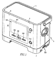
A System Architecture FIG. 1 shows an embodiment of a
ベンチレータ2は、内部6と、外部表面10を備える外部8とを持つハウジング4を含む。具体例では、ベンチレータ2は、持ち歩けるように設計されていて、従って、ベンチレータを持ち運ぶか又は移動するのを容易にするために、ハウジングの上部に旋回軸結合されたハンドル11を含む。図1では収容された位置に示されるハンドル11は、図3の仮想線描画では、直立した位置で示されてもいる。
図1の例では、ベンチレータ2は、ベンチレータハウジング4の前の外部表面10に配置されているユーザインタフェース300を含む。幾つかある特徴の中で特に、ユーザインタフェース300は、ベンチレータ及び/又は患者170に関する多くのパラメータ(例えば、限定されるものではないが、圧力、ボリューム、流量レート)(図4、図5及び図6)を示すように構成されたスクリーン又はディスプレイ302を含む。ユーザインタフェース300は、また、例えば、ベンチレータの動作を制御し、及び/又はスクリーン302に表示されるパラメータ(明確にでなく示される)の中でナビゲートするために、ユーザにより操作される複数の入力部材304、306、308、310及び312を含む。例えば、限定されるものではないが、1つの非限定的な実施例では、入力部材310はON/OFFボタンを有し、入力部材312はベンチレータ2の様々な動作モード又はユーザインタフェース300のスクリーン302に見える様々な表示を切り換えるためのモードボタンを有する。同様に、入力部材304、306及び308は、例えば、限定されるものではないが、ユーザインタフェースを介してベンチレータの様々な特徴をナビゲートし、選択し及び/又はプログラムするために、ユーザにより使用可能なボタンを有する。
In the example of FIG. 1, the
しかしながら、ユーザインタフェース300の特定のアレンジメントは、本発明を限定する態様であることを意味するものではないことが、理解されるだろう。特に、ベンチレータ2は、明細書に示され説明されている以外の任意の適切な構成との任意の既知の又は適切な代わりのユーザインタフェースを持てることが、理解されるだろう。例えば、ダイヤルを供給することを予期される本発明は、入力部材304、306、308、310、及び312に加えて、又はその代わりに、タッチパッド、ローラーボール、マウス又は他の入力装置をわかっている。また、入力部材304、306、308、310、及び312に加えて、又はその代わりに、ディスプレイ203が入力装置として機能するように、ディスプレイ203は、タッチスクリーンディスプレイとして設定できる。また、本発明は、遠隔制御装置を介して操作できるベンチレータ2を考察するので、入力部材304、306、308、310、及び312が除去できる。
However, it will be understood that the specific arrangement of the
ベンチレータ2は、また、好ましくは、明細書で定義されるような様々な異なるインタフェース機構320、322、324、326、328、及び330を持つ。例えば、限定されるものではないが、ベンチレータ2は、図1に示される例におけるベンチレータハウジング4の底部に置かれる容器のような容器320を含む。本発明の一つの非限定的な実施例において、斯様な容器320は、電気的にベンチレータ2を電源(例えば、模式的に図12に示され、以下により詳細に説明されている、交流(AC)電源402及び鉛蓄バッテリバッテリ電源406を参照)に接続するのに適している。例えば、限定されるものではないが、図2及び図3に示される5つの付加的なインタフェース機構322、324、326、328、及び330のような、既知であり、適切なタイプ、適当な数及び/又は設定のインタフェース機構は、本発明の範囲内で供給できる。
The
斯様なインタフェース機構(例えば、限定されるものではないが、容器、コネクタ)は、例えば、限定されるものではないが、ベンチレータ2を(例えばイーサネット(登録商標)ネットワークにより)インターネットに、例えば、限定されるものではないが、プリンタ(図示せず)若しくはコンピュータ(図示せず)に、又はパルス酸素濃度計、二酸化炭素モニタ、若しくは代わりのガス供給源(例えば、模式的に図4、図5及び図6に示されて、以下に説明されている任意の酸素源31を参照)に接続するためのような任意の既知又は適切な目的のために使用できることも理解されるだろう。
Such interface mechanisms (eg, but not limited to containers, connectors) may include, but are not limited to, for example,
図4、図5及び図6、それぞれは、簡略化された形式でベンチレータ2の3つの実例的構成を示す。特には、図4は、近位の圧力検知なしの受動的な呼気を供給するように構成されるベンチレータの部品を示す。図5は、近位の圧力検知を持つ受動的な呼気を供給するように構成されるベンチレータの部品を示す。加えて、図6は、能動的な呼気を供給するように構成されるベンチレータの部品を示す。
4, 5 and 6 each show three illustrative configurations of the
更に特に、図4に模式的に示されるように、ベンチレータ2は、例えば、吸気ポート30を通ってベンチレータハウジング4に入る空気38’(外気)から及び/又は酸素のような適切な補足的なガスと空気38’との混合物からガス38の流れを生成するように構成される流れ生成器36を含む。補足的な酸素は、図4、図5及び図6の簡略化された形式で示される、酸素源31のような上述したベンチレータアクセサリの1つから供給できる。本発明の一つの非限定的な実施例において、任意である酸素源31は、低い流量(この例では模式的に示され明細書で説明される迅速接続バルブ取付である、例えば、限定されるものではないが、インタフェース機構328のような上述したインタフェース機構の1つを介して、ベンチレータ2に接続されている、例えば、限定されるものではないが、約0―50psi及び毎分約15リットル(LPM)の酸素ブレンダ)を有する。
More particularly, as shown schematically in FIG. 4, the
実例的な実施例において、ベンチレータ2は、また、ベンチレータハウジング4に入る外気38’をフィルタリングするための吸気フィルタ32を含む。以下に詳細に述べられるように、外気38’及び/又は任意の補足的な酸素源31からのガスは、流れ生成器36に到達する前に、好ましくは吸気エアフローアセンブリ200を通るように向けられる。例えば、流れ生成器36は、ベンチレータ2により必要とされる所望の圧力及び流量のガス38を生成するための羽根車デザイン(部分的に、図11に示される)を持つブラシレス直流(DC)モーター(図示せず)を持つ送風アセンブリを有するマイクロタービンである。一つの非限定的な実施例において、マイクロタービン36は、約3,000−42,000毎分回転数(rpm)の速度で動作可能である。しかしながら、流れ生成器36は、例えば、限定されるものではないが、圧縮器、ファン、羽根車、送風機、ピストン又は送風装置のような、外気より大きい圧力でガス38の流れを引き起こすように構成された任意の既知又は適切な装置であり得ることは、理解されるだろう。
In the illustrative embodiment,
図4を続けて参照すると、流れ生成器36を出るガス38の流れは、ハウジング4内に配置されている第1の流量要素42と流体連通している、オプション的流量スクリーン(フィルタ)40を通過する。第1の流量要素42は、ベンチレータ内に配置されるので、ここでは、機械的流量要素42とも称される。流れ生成器36の放出口付近に配置される機械的流量要素42は、例えば、限定されるものではないが、オリフィス(開口部)又はバルブのような機械的要素である。ガス38の流れが機械的流量要素42を通過するとき、機械的流量要素42は、圧力降下を生じるように設計されている。しかしながら、流量要素の任意の既知若しくは適切な代わりの数及び/又は構成が、本発明の範囲内において、適切な流量のガス38をベンチレータ2に供給するために使用できることは、理解されるだろう。
With continued reference to FIG. 4, the flow of
第1の(機械的)流量センサ46は、機械的流量要素間の圧力降下に基づいてガス流38の流率を測定するために、機械的流量要素42と並行して供給される。加えて、示されてここで説明される例では差動圧力センサである、第2の流量センサ50も、ライン52及び54を介して機械的流量要素42間の圧力降下を測定することにより、ガス38の流率を測定するために供給される。第2の流量センサ50は、このように、第1の流量センサ46によりなされてはいるが冗長な態様で、ガス38の体積流量を監視する。第2の流量センサ50は、ここでは、モニタ流量センサ50とも称される。図5及び図6の例に関して後述されるように、流量センサ46及び50、並びにベンチレータ2内の他のセンサは、ベンチレータの様々な動作モードに対応する複数の異なる設定に対して設定可能及び再設定可能であることが、理解されるだろう。ベンチレータが単に両方の流量センサを持つ必要がないことは、更に理解できるだろう。加えて、本発明は、更にまた、流れ生成器に供給される電力量、流れ生成器の速度等に基づくような他の技術を用いて流率又は流率を示すパラメータを測定することで、流量センサの一方又は両方を排除できることも意図する。
A first (mechanical) flow sensor 46 is provided in parallel with the
制御機械的圧力センサ86は、排出口44を通って流れ生成器36から、外部導管144へ、最後に患者インタフェース146へガス38の流れを供給する内部導管143に動作的に結合される。例示的制御機械的圧力センサ86は、自動ゼロ点バルブ87を通って内部導管143に接続されている。センサ86は、ベンチレータ2の排出口44で、又は周りでの圧力を監視するために用いられる静圧センサである。加えて、モニタ機械的圧力センサ88が、内部導管143に動作的に結合されている。冗長な様式で、モニタ機械的圧力センサ88も、排出口44で、又は周りでの圧力を監視するために用いられる静圧センサである。ベンチレータ2での使用に適した他のセンサは、限定されるものではないが、内部導管143に動作的に結合され、流れ生成器36を出るガス38の流れの温度を監視するために使用される温度センサ51及び53、及び例えば計算された体積流量の高さ調整を可能にする気圧を測定するための気圧センサ55を含む。
The control mechanical pressure sensor 86 is operatively coupled to the
図4の例に示される近位の圧力検知構成なしの受動的な呼気に使用されないにもかかわらず、ベンチレータ2は、また、例えば図6に示されるように、ベンチレータが能動的呼気構成モードに構成されるとき使用される能動的呼気制御アセンブリ90を含む。最後に、ベンチレータ2は、図4、図5及び図6に模式的に示されるコントローラ98を含む。コントローラ98は、選択的にベンチレータを制御するために、上述した部品の各々と電気的に接続されて通信するのに適している。
Despite not being used for passive exhalation without the proximal pressure sensing configuration shown in the example of FIG. 4, the
図4の例において、ベンチレータ2は、ベンチレータの排出口44及び患者インタフェース146と相互接続する1本の外部導管144を持つ。従って、ベンチレータ2の患者回路150は、単一の肢回路である。単一の外部導管144は、排出口44から患者インタフェース146に、そして最後に患者170の気道160にガス38の流れを送ったり(図4、図5及び図6に簡略化された形式で部分的に示される)、換気サイクルの呼気のフェーズの間、患者170により呼気される呼気ガス38”を運んだりする。図4の単一の肢患者回路150は、外気に呼気ガス38”を排気する(すなわち、放出する)ための受動的な呼気装置152(例えば限定されるものではないがバルブ、オリフィス(開口部)、ポート又は他の排出装置)を含む。
In the example of FIG. 4, the
明細書に説明されている例に示される患者インタフェース146は、説明を簡単にするため非観血的マスク146であるが、明細書で規定されているような既知又は適切な代わりの患者インタフェースが、患者回路150(図4)、150’(図5)、150”(図6)を持つ適切な構成で使用できることは、理解されるだろう。受動的な呼気装置152が、患者回路150、患者インタフェース146又は両方に結合されてよいことも理解されるだろう。
The
ここで図5を参照して、ベンチレータ2の部品が、近位の圧力検知を持つ受動的な呼気を供給するように設定されて模式的に示される。この設定において、ベンチレータ部品及び既定のセンサ設定は、主に、図4に関して前述された近位の圧力設定のない受動的な呼気に関するものと同じである。しかしながら、追加的に、ハウジング4に供給される近位の圧力センサ48は、明細書で規定されるように、ライン56に接続される患者インタフェース146の近傍に配置される、プローブ57(例えば、導管)を介して、単一の肢患者回路150’の単一の外部導管144’と流体連通するように設定されている。
Referring now to FIG. 5, the
図6は、能動的呼気設定におけるベンチレータ2及びその部品の模式図を示す。斯様な設定において、ベンチレータ2は、排出口44と流体連通する代わりの単一の肢患者回路150”を含む。特に、外部導管144”に加えて、単一の肢患者回路150”は、また、近位の流量要素154及び能動的呼気装置156(例えば、限定されるわけではないが、バルブ)を含む。近位の流量要素154は、患者インタフェース146”にだいたいすぐ近くの患者回路に置かれる機械的要素であり、ガス38の流れ及び/又は呼気ガス38”が当該要素を通るとき、圧力降下を生じるように設計されている。
FIG. 6 shows a schematic diagram of the
具体例では、能動的呼気装置156は、単一の肢患者回路150”に配置され、換気サイクルの呼気のフェーズの間、呼気ガス38”の二酸化炭素流しを可能にするために低抵抗を供給するように構成された、比例して制御される圧力安全弁である。能動的呼気装置156が、患者回路150”、患者インタフェース146”又は両方に結合されてもよいことは、理解されるだろう。能動的呼気装置156は、治療損失の場合(例えば、限定するわけではないが、ベンチレータ故障)に、抗呼吸停止要件を満たすため、最小の呼気抵抗を供給するように構成される。特に、能動的呼気装置156は、斯様な要件を満たすために、抗呼吸停止装置158(図6に簡略化された形式で示される)を含む。一つの非限定的な実施例において、抗呼吸停止装置は、例えば、限定されるものではないが、ゴム又は他の適切な物質から作られるフラッパ弁158であり、これは、能動的呼気装置156の対応する開口部(明確にではなく、示されている)を開放するために、ベンチレータ2の故障又は部分的な故障の場合に、偏向するように構成されている。斯様な開口部は、外気と流体連通している。従って、フラッパ弁158は、患者170が、ベンチレータ2の斯様な故障の場合に外気を吸い込むための最低限の可能性を持つことを確実にする。
In an example, the active expiratory device 156 is placed in a single
図6の例において、コントローラ98は、能動的呼気制御アセンブリ90に結合され、従って能動的呼気装置156に動作的に結合される。能動的呼気制御アセンブリ90は、換気サイクルの呼気のフェーズの間、患者170が呼気するときのバイアス流れを制御するために、能動的呼気装置156の絞り157(図6に簡略化された形式で示される)を制御する圧力ユニットである。例示的能動的呼気制御アセンブリ90は、絞り157からのパイロット圧力を速く減らして、これにより、患者呼気が開始されるとき、絞り157が完全に開くことができるように構成されたダンプ弁91と、2つのバルブ91、92の間に供給されるオリフィス(開口部)93と組み合わせて、バイアス流れを制御する比例弁92とを含む。
In the example of FIG. 6, the
ベンチレータ2が、単一の肢又は二重肢構成において操作できる小さくて、軽量で、用途が広いベンチレータであって、圧力サポート療法又はボリューム制御療法の両方を提供できることは、理解できるだろう。その上、圧力サポート療法又はボリュームに基づいた療法は、非観血的システム、例えば、呼気バルブを通るような意図的なガス漏出を持つ単一の肢システムで遂行できる。
It will be appreciated that the
下記の表1は、本発明のベンチレータの具体例のための仕様をリストする。

B ポートシステム
開示されたベンチレータは、限定されるわけではないが、患者170に対する圧力サポートベンチレーション療法を供給するための第1のモード及び患者にボリューム制御ベンチレーション療法を供給するための第2のモードを含む、複数の異なる動作モードで動作可能なことは、理解されるだろう。更に、斯様なモードの中で、ベンチレータ2は、例えば、限定されるものではないが、図4の近位の圧力検知設定なしの上述した受動的な呼気、図5の近位の圧力検知設定を持つ受動的な呼気、及び図6の能動的呼気設定のような、任意の適切な呼気設定を持つことができる。
B Port System The disclosed ventilator includes, but is not limited to, a first mode for providing pressure support ventilation therapy to the
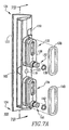
これらのモード及び/又は設定の一方から他方へのベンチレータ2の切換えは、例えば、限定されるものではないが、置き換えられたり及び/又は再設定されるべきセンサ及び/又は患者回路のようなベンチレータ2の特定のフィーチャを必要とする。伝統的に、従来のベンチレータでは、これは、多大な量のベンチレータの分解及び/若しくは操作、又は異なるベンチレータの使用を共に必要とした時間のかかる労力であった。これは、本発明のベンチレータ2の前には、前述の動作モード及び設定の全てが、単一のベンチレータ装置で利用できなかったからである。ここで説明されるように、開示されたベンチレータがこれらの不利な点を克服する1つの態様は、ベンチレータ2が所望のモードに速く且つ容易に設定され及び/又は再設定できるようにする、複数の交換可能なポートブロック102(図3、図7A及び図7B)、102’(図8)及び102”(図9)を持つポートシステム100を供給することによる。
The switching of the
特に、ポートシステム100は、上述したセンサ(例えば、限定されるものではないが、機械的流量センサ46、近位の圧力センサ48、モニタ流量センサ50)、及びそのための複数のプローブ(例えば、限定されるものではないが、導管)を含む。例えば、例示的な機械的流量センサ46は、第1の機械的流量プローブ52及び第2の機械的流量プローブ54を含み、近位の圧力センサ48は、少なくとも一つの近位の圧力プローブ56を含み、モニタ流量センサ50は、第1のモニタ流量プローブ60及び第2のモニタ流量プローブ62を含む。プローブ52、54、56、60、62は、ベンチレータハウジング4の外部表面10上の一つの共通の位置でアクセス可能である。各ポートブロック102(図3、図4、図7A及び図7B)、102’(図5及び図8)及び102”(図6及び図9)は、ベンチレータ2が分解される必要なしに、プローブ52、54、56、57、58、59、60、62、63及び65(図6に全て示される)並びに対応するセンサ46、48、50を設定するために、上述した共通の位置で、又はその周りでベンチレータハウジング4に選択的に結合されるように構成された着脱可能なルーティング要素103(図3、図4、図7A及び図7B)、103’(図5)及び103”(図6)を含む。本発明のこの観点は、ポートブロック102の着脱可能なルーティング要素103がベンチレータハウジング4から離れて分解組み立て図で示される、図3を参照して更に理解されるだろう。
In particular, the
図2に示されるように、ポートシステム100の締結機構116は、着脱可能なルーティング要素103をハウジング4に固定するように構成される。例示的締結機構116(図3にも示される)は、着脱可能なルーティング要素103の穴119を通って延在するように構成された単一の締着具118である。図3、図7A及び図7Bにも示されるように、着脱可能なルーティング要素103は、第1の側部120、第1の側部の反対側に配置された第2の側部122、第1及び第2の対向する端部124及び126、並びに、第1の側部120から第2の側部122へ延在する複数の通路104、106、108、110、及び112(図7B;図4に模式的に示される通路104、106、108、110、112、及び114も参照)を含む。明細書において使用されるように、用語「通路」は、任意の既知又は適切な穴、通り道、導管、又は少なくとも対象物の一部を通って延在する経路を指し、そこを通る流体(例えば、ガス)の移動を可能にするように構成される能動的通路、及びそこを通る流体(例えば、ガス)の移動を妨げるように構成される非能動的通路(すなわち、閉じられる通路)両方を明確に含む。選択されたポートブロック(例えば、102)の着脱可能なルーティング要素103がベンチレータハウジング4に結合されるとき、その通路104、106、108、110、112及び/又は114は、ベンチレータの選択された動作モードに対応する所望の既定されたセンサ設定を確立するためにプローブ52、54、56、60、62及び/又は63と協働する。
As shown in FIG. 2, the
開示の効率のために、ポートブロック102の一つだけの動作が詳述されるだろう。しかしながら、ポートシステム100の他の交換可能なポートブロック(例えば、限定されるものではないが、ポートブロック102’及び102”)が実質的に同じ態様で使用されることは、理解されるだろう。再び図3を参照して、ベンチレータハウジング4の外部表面10は、ポートブロック102の着脱可能なルーティング要素103を受けるように構成された凹部64を含む。よって、図2に示されるように、着脱可能なルーティング要素103の第2の側部122は、着脱可能なルーティング要素103が凹部64に正しく挿入されるとき、ベンチレータハウジング4の凹部64に隣接する外部表面10に関して実質的に同じ平面にある。このように、本発明の交換可能なポートブロックデザインは、ベンチレータハウジング4から外向きに延在する望ましくない突起をつくらない。
For the efficiency of the disclosure, only one operation of the
図3の例において、凹部64は、着脱可能なルーティング要素103(図3、図7A及び図7B)の第1の側部120から外向きにぞれぞれ延在する第1及び第2の突起132及び134を受けるように構成された第1及び第2の開口部66及び68を含む。図7Aと図7Bの断面図とに示されるように、それぞれ、突起132及び134は、好ましくは封止部136及び140を含む。封止部136及び140(Oリング封止部138及び142も参照)は、例えば、限定されるものではないが、シリコンゴムのような任意の既知の又は適切な物質から作られ、着脱可能なルーティング要素103とベンチレータハウジング4との間からガス38(図4、図5及び図6)の流れを意図的でなく漏れることに抗するために、突起132、134、137及び141(図7Bに最も示される)の対応する部分にそれぞれ配置されるように構成される。図7A及び図7Bの例の着脱可能なルーティング要素103は、突起132及び134からそれぞれ外向きに延在するニップル137及び141を含み、封止部は、それぞれ突起132及び134の対応する溝に配置されている細長い封止部136及び140と、それぞれニップル137及び141の対応する溝に配置されたOリング封止部138及び142とを含む。
In the example of FIG. 3, the recess 64 includes first and second extensions that extend outwardly from the
着脱可能なルーティング要素103は、また、その第2の側部122で又は周りに、着脱可能なルーティング要素103の第1の端124と端126との間に配置されたフィンガタブ130を含む。フィンガタブ130は、例えば、異なるモードでの動作のためにベンチレータ2のセンサの設定を変更するため、ルーティング要素103を着脱可能なルーティング要素103’(図5及び図8)又は103”(図6及び図9)の異なるものと交換することが望まれるとき、ベンチレータハウジングの凹部64から着脱可能なルーティング要素103の除去を容易にするように構成されている。しかしながら、例示的なフィンガタブ130以外の任意の適切な変形例の機構が、着脱可能なルーティング要素103の除去を容易にするため任意の適切な構成で使用できることは、理解されるだろう。本発明の範囲を逸脱することなく、着脱可能なルーティング要素103が任意の既知の又は適切な代替設定を持つことも理解されるだろう。
The
例えば、図8及び図9は、本発明による種々異なるポートブロック102’及び102”の2つの非限定的な実施例をそれぞれ示す。後述されるように、図8のポートブロック102’は、図5に模式的に示される既定のセンサ設定を確立するように構成された着脱可能なルーティング要素103’を含み、図9のポートブロック102”は、図6に模式的に示される既定のセンサ設定を確立するように構成された着脱可能なルーティング要素103”を含む。特に、図3、図4、図7A及び図7Bのポートブロック102と同様に、ポートブロック102’の着脱可能なルーティング要素103’は、それぞれ第1及び第2のニップル137’及び141’を持つ第1及び第2の突起132’及び134’を持つ。
For example, FIGS. 8 and 9 show two non-limiting examples of different port blocks 102 ′ and 102 ″, respectively, according to the present invention. As described below, the
着脱可能なルーティング要素103’は、また、図7A及び図7Bに関して前述されたような封止部を含むと考察される(これらは図8に示されていない)。後述されるように、着脱可能なルーティング要素103’の主要な特徴(フィーチャ)は、その通路(図5に模式的に示される通路104’、106’、108’、110’、112’及び114’参照)の構成に関してである。一つの通路108’は、図5に示されるように、近位の流量センサ48を患者回路150’に接続するように構成される。この通路108’は、示されるように、着脱可能なルーティング要素103’の外部表面から外向きに延在するポート109’を通って延在する。
The removable routing element 103 'is also considered to include a seal as described above with respect to FIGS. 7A and 7B (these are not shown in FIG. 8). As will be described later, the main feature of the
図6に関して説明されるように、図9の着脱可能なルーティング要素103”の通路104”、106”、108”、110”、112”及び114”(図6に模式的に示される)は、着脱可能なルーティング要素103’(図5及び図8)及び着脱可能なルーティング要素103(図3、図4、図7A及び図7B)のものとは異なっていて、よって、図6に模式的に例示されるセンサ設定を確立するように構成されている。特に、図9に示されるように、着脱可能なルーティング要素103”は、第1及び第2の突起132”及び134”を含む。第1の突起132”は、単一のニップル137”を含み、第2の突起134”は、3つのニップル141”、145”及び147”を含む。具体例では、突起132”及び134”とニップル141”、145”及び147”とは、図7A及び図7Bに関して前述されたような、適切な封止部(説明の簡明さのための図9に示されていない)を含む。着脱可能なルーティング要素103”の第1、第2及び第3の通路104”,106”及び108”は、所望のプローブ/センサ接続を提供するために、着脱可能なルーティング要素103”のそれぞれ対応する第1、第2、及び第3のポート105”、107”及び111”を通って延在する。
As described with respect to FIG. 6, the
ポートシステム100のポートブロック102(図3、図4、図7A及び図7B)、102’(図5及び図8)及び102”(図6及び図9)が明細書に示され説明されている3つ以外の任意の適切な構成を有し得るという事実に加えて、これらが任意の適切な物質から、任意の適切なプロセス又は方法により作られることも、理解されるだろう。1つの非限定的な例では、交換可能なポートブロック102、102’、102”は、単一の部分成形プラスチック部品であり、従って、製造するのに比較的容易で安価である。
Port blocks 102 (FIGS. 3, 4, 7A and 7B), 102 ′ (FIGS. 5 and 8) and 102 ″ (FIGS. 6 and 9) of the
再び図4を参照すると、近位の圧力検知設定なしの受動的な呼気のためのセンサ(例えば、限定されるものではないが、機械的流量センサ46、近位の圧力センサ48及びモニタ流量センサ50)の既定の設定、特に、斯様な設定を確立するための着脱可能なルーティング要素103の使用が説明されるだろう。特に、動作時、特定のモード及び/又は呼気設定に従ってベンチレータ2を操作するための決定がなされるとき、そのモード及び/又は設定に対応する患者回路(例えば、限定されるわけではないが、単一の肢患者回路150)が選択されてベンチレータ2の排出口44に結合される。代わりに、患者回路150は、例えば一つの呼気装置(例えば、受動的な呼気装置152)を他の呼気装置(例えば、異なる受動的な呼気装置、例えば、図6に示される能動的呼気装置156)と交換することにより、及び/又は患者インタフェース146を取付けるか若しくは変更することにより、要望通り設定されるか又は再設定できる。換言すれば、患者回路150の単一の外側の導管144は、呼気装置156及び/又は患者インタフェース146が例えば一つ以上の速く変えられる器具(例えば、限定されるわけではないが、スリップ器具)(明確には示されていない)により導管144に選択的に結合された状態で、ベンチレータ2の排出口44に取付けられたままであり得る。このように、着脱可能で、取り替えられ、又は丸ごと交換可能である患者回路と、部分として選択的に設定可能及び/又は再設定可能である患者回路は、本発明の範囲内である。
Referring again to FIG. 4, sensors for passive exhalation without a proximal pressure sensing setting (eg, but not limited to mechanical flow sensor 46, proximal pressure sensor 48, and monitor flow sensor). 50) the default settings, in particular the use of the
患者回路150(図4)、150’(図5)又は150”(図6)を選択又は設定した後に、対応するポートブロック102(図3、図4、図7A及び図7B)、102’(図5及び図8)又は102”(図6及び図9)が、選択されて、ベンチレータハウジング4(図2に最も示される)に取付けられる。上記されたように、様々な既定のセンサ設定を確立するために、着脱可能なルーティング要素103(図3、図4、図7A、図7B)、103’(図5及び図8)及び103”(図6及び図9)の各々は、既定の態様でセンサプローブと選択的に協働するように構成される通路の種々異なるアレンジメントを持つ。特に、図4の例では、着脱可能なルーティング要素103は、第1、第2、第3、第4、及び第5の能動的通路104、106、108、110及び112と一つの非能動的通路114とを含む。第1の能動的通路104は、第1の機械的流量プローブ52を第1のモニタ流量プローブ60に接続するために、第2の能動的通路106と協働する。第3の能動的通路は、例えば、単一の近位の圧力プローブ56を介して、近位の圧力センサ48を外気と接触させる。第4及び第5の能動的通路110、112は、示されるように、第2の機械的流量プローブ54を第2のモニタ流量プローブ62に接続するために、互いに協働する。最後に、能動的呼気制御アセンブリ90は図4の近位の圧力検知設定なしに受動的な呼気で使用されないので、能動的呼気制御プローブ63は、非能動的である(ブロックされている)通路114と接続されている。
After selecting or setting the patient circuit 150 (FIG. 4), 150 ′ (FIG. 5) or 150 ″ (FIG. 6), the corresponding port block 102 (FIGS. 3, 4, 7A and 7B), 102 ′ ( 5 and 8) or 102 "(FIGS. 6 and 9) are selected and attached to the ventilator housing 4 (best shown in FIG. 2). As described above, removable routing elements 103 (FIGS. 3, 4, 7A, 7B), 103 ′ (FIGS. 5 and 8), and 103 ″ to establish various predefined sensor settings. (FIGS. 6 and 9) each have different arrangements of passages configured to selectively cooperate with the sensor probe in a predetermined manner, particularly in the example of FIG. 103 includes first, second, third, fourth and fifth
従って、センサの全てが、適当に交換可能なポートブロック(例えば、限定するわけではないが、102)をベンチレータハウジング4に単に取付けることにより、ベンチレータ2の選択された動作モードに対応する所望の既定の設定に設定可能なことは、理解されるだろう。しかしながら、ポートブロック102(図3、図4、図7A及び図7B)、102’(図5及び図8)及び102”(図6及び図9)の着脱可能なルーティング要素103(図3、図4、図7A及び図7B)、103’(図5及び図8)及び103”(図6及び図9)の通路の正確なアレンジメントが、本発明の限定的態様を意味しないことは、理解されるだろう。本発明のポートシステムは、同じベンチレータセンサが単にポートブロック102(図3、図4、図7A及び図7B)、102’(図5及び図8)、102”(図6及び図9)を交換することにより、すなわち、他の検知素子を加えるか又は取り除くことなしに、速くて容易に再設定できる。
Thus, all of the sensors are connected to the
図5に示され前述されたように、ベンチレータ2の部品は、図4に関して説明された近位の圧力検知設定なしの受動的な呼気に対するように、近位の圧力検知設定を持つ受動的な呼気に対して、実質的に同様に配置される。主要な違いは、患者回路150’の外部導管144、近位の患者インタフェース146と流体連通されている、第2の近位の圧力プローブ57を含むことである。第2の交換可能なポートブロック102’の着脱可能なルーティング要素103’は、この近位の圧力プローブ57を収容するように構成されている。特に、着脱可能なルーティング要素103と同様に、着脱可能なルーティング要素103’は、第1、第2、第3、第4、及び第5の能動的通路104’、106’、108’、110’及び112’と一つの非能動的通路114’とを含む。第1及び第2の能動的通路104’及び106’は、第1の機械的流量プローブ52を第1のモニタ流量プローブ60に接続するために協働する。しかしながら、近位の圧力プローブ56を外気と接触させた着脱可能なルーティング要素103の第3の通路108とは異なり、着脱可能なルーティング要素103’の第3の通路108’は、示されるように、第1の近位の圧力プローブ56を第2の近位の圧力プローブ57に接続する。第4及び第5の能動的通路110’及び112’は、第2の機械的流量プローブ54及び第2のモニタ流量プローブ62を接続し、能動的呼気プローブ63は非能動的通路114’に接続されている。
As shown in FIG. 5 and described above, the
ここで図6を参照すると、ベンチレータ2及びその部品が能動的呼気のために設定されるとき、単一の肢患者回路150”は、追加的に、上述した近位の流量要素154及び能動的呼気装置156を含む。従って、例えば、限定されるわけではないが、第3及び第4の近位の圧力プローブ58及び59並びに能動的呼気装置プローブ65のような多くの追加プローブが必要とされる。これら及び他のプローブの設定は、交換可能なポートブロック102”の第3の着脱可能なルーティング要素103”、特に、第1、第2、第3及び第4の能動的通路104”、106”、108”及び110”と第1及び第2の非能動的通路112”及び114”により確立される。
Referring now to FIG. 6, when the
第1の能動的通路104”は、第1のモニタ流量プローブ60を第2の近位の圧力プローブ57に接続し、第2の能動的通路106”は、第1の近位の圧力プローブ56を第4の近位の圧力プローブ59に接続し、第3の能動的通路108”は、第2のモニタ流量プローブ62を第3の近位の圧力プローブ58に接続する。このように、近位の圧力プローブ57及び58は、近位の流量要素154の両側のガス38、38”の流量を監視するため、センサ50と通じている。第4の能動的通路110”は、第1の能動的呼気制御プローブ63を能動的呼気装置プローブ65に接続する。よって、この構成で、能動的呼気制御アセンブリ90は、コントローラ98を介して能動的呼気装置156を監視し制御するために能動的に使用される。機械的流量センサ46と第1及び第2の機械的流量プローブ52、54とは、この構成では必要とされず、従って、それぞれ第1及び第2の非能動的通路112”及び114”に結合される。
The first
前述からみて、本発明は、ベンチレータが分解されるか又は交換される必要なしに、単一のベンチレータ2が、様々なタイプのベンチレーション療法を提供するために速くて容易に設定又は再設定され得ることは、理解されるだろう。特に、上述した受動的な呼気装置152(例えば、限定されるわけではないが、受動的な呼気バルブ、オリフィス(開口部))を使用して、患者170にボリューム制御ベンチレーション療法(ボリュームベンチレーションとも呼ばれる)を提供するベンチレータ2の能力は、ユニークである。この組合せを使用する効率的な患者ベンチレーションは、以前は実質的に不可能であると考えられていた。
In view of the foregoing, the present invention allows a
特に、生命サポート状況、しばしばボリューム制御の場合のように、患者のためのガス38の所望の吸入量を正確に維持することが絶対に重要であるとき、ガス38”の外気への受動的な漏出を可能にすることは、いくらか直観に反している。従って、既知のボリューム制御(すなわち、生命サポート)ベンチレーションシステム(図示せず)は、伝統的に、二重肢患者回路の一部として役立つ能動的呼気装置を必要とした(すなわち、患者回路は、一つは換気サイクルの吸気フェーズの間の患者吸入のため、一つは換気サイクルの呼気フェーズの間の患者呼気のため、少なくとも2つの外部導管を含む)。これは、要求されるより、より大きく且つより複雑だったベンチレータ設計に結果としてなる傾向があった。このように、ベンチレータは、病院、指定された看護センター、又はベンチレータが医師、医療専門家又は訓練された人員により密接に監視され維持できる他の施設から外の使用のためには一般に誘導されていなかった。
Especially when it is absolutely important to accurately maintain the desired inhalation volume of
ボリューム制御ベンチレーション治療、又は受動的な呼気を使用して所望の吸気1回換気量を供給する本発明のベンチレータの能力は、適切なベンチレーション治療を受け続けながら、一つの位置から他の位置へ比較的容易に患者が移動可能にする単一の実質的に携帯の軽量ベンチレータ2を供給することにより、これら及び他の不利な点を克服する。従って、開示されたベンチレータは、比較的能動的ライフスタイルを維持する機会を患者に与える。
The ability of the ventilator of the present invention to deliver the desired inspiratory tidal volume using volume control ventilation therapy, or passive exhalation, allows one to move from one position to another while continuing to receive appropriate ventilation therapy. These and other disadvantages are overcome by providing a single substantially portable
更に特に、例えば図5を参照して前述されたように、例示的ベンチレータの患者回路150’は、好ましくは単一の外部の導管144’を含む単一の肢回路150’であり、当該単一の肢回路は、その排出口44でベンチレータ2に選択的に接続可能である、別々の自己充足的なアセンブリを有するか、又は単一の導管144’に選択的に接続可能な受動的な呼気装置152及び患者インタフェース146のような部品と選択的に設定可能である。いずれにしても、単一の導管144’は、患者インタフェース146とベンチレータ2の排出口44とを相互接続する。受動的な呼気装置152は、患者のインタフェース146近くの単一の導管144’と結合される。制御ボリューム(ボリュームベンチレーション)モードで動作するとき、流れ生成器36と動作的に結合されるベンチレータ2のコントローラ98は、吸気1回換気量とも呼ばれる、吸入量を持つガス38の流量を生成するために流れ生成器36を選択的に制御するのに適している。本発明は、また、吸気流量プロフィールが所定の吸気時間にわたって供給されるボリュームベンチレーションを供給することも考察する。
More particularly, as described above with reference to FIG. 5, for example, the exemplary ventilator
単一の肢患者回路150’は、換気サイクルの吸気フェーズの間、吸入量を持つガス38の流れを患者170の気道160に送る。明細書に説明され示される例において、ガス38の流れの吸入量及び呼気ガス38”両方は、単一の肢患者回路150’の単一の導管144’内で運ばれる。受動的な呼気装置152の機能は、患者により呼気した呼気ガス38”に存在する二酸化炭素を外気に流すことであることは、理解されるだろう。その後、ガス38の流れの新鮮な吸入量が、次のベンチレーションサイクルの吸気フェーズの間、患者に送られる。
A single limb patient circuit 150 'delivers a flow of
患者に対して規定された特定の吸入量、又はボリュームベンチレーションは、限定されるわけではないが、患者が被る疾患のタイプ及び疾患の経過のステージを含む様々な異なる要因に依存することは、理解されるだろう。一つの非限定的な実施例では、ベンチレータ2、特にそのためのコントローラ98は、換気サイクルの吸気フェーズの間、患者に送られる所望の吸入量をガス38の流れが持つようにさせる流れ生成器36を、必要に応じて選択的に調整するのに適している。これは、自動的になされ得る。代わりに、ベンチレータ2は、患者自身により、又は好ましくは医師又は介護者により、上述したユーザインタフェース300を使用してプログラムできる。換気サイクルの呼気のフェーズの間、患者170により呼気される少なくとも呼気ガス38”の一部は、受動的な呼気装置152により外気に放出される。従って、他の利点の中では、ベンチレータ2は、上述した2重肢患者回路(図示せず)又は既知のボリューム制御ベンチレーションシステムの能動的呼気装置(図示せず)の何れも必要とされないように、受動的な呼気を使用して、効率的なボリューム制御ベンチレーション療法を供給する。
The specific inhalation volume or volume ventilation specified for a patient depends on a variety of different factors including, but not limited to, the type of disease experienced by the patient and the stage of the course of the disease, Will be understood. In one non-limiting example, the
ベンチレータ2のコントローラ98は、漏出補償を提供するのにも好ましくは適している。例えば、限定されるものではないが、コントローラ98は、患者回路150’の漏出を検出し、漏出検出に応じて、ベンチレータ2の動作に関して適切な調整をするために、適切な漏出補償ルーチンを実行するのに適している。適切な漏出補償ルーチンの1つの非限定的な例は、本発明の譲受人から市販されているAutotrack(登録商標)ソフトウエアプログラムである。漏出見積もり/補償技術の例は、米国特許第5148802号、第5313937号、第5433193号、第5632269号、第5803065号、第6029664号、第6626175号、第6360741号、第6920875号、第6948497号、及び第7100607号で提供され、これらの内容は、参照によりここに組み込まれる。
The
代わりに、本発明は、既知であるか/意図された漏出若しくは固定の漏出装置、又は圧力関係に対して既知の漏出率を持つ排出ポートを提供することを考察する。この関係は、任意の所与の圧力に対する漏出率を決定するために使用できる。 Instead, it is contemplated that the present invention provides a known / intended leak or fixed leak device, or an exhaust port with a known leak rate for pressure relationships. This relationship can be used to determine the leak rate for any given pressure.
加えて、本発明は、患者とベンチレータとの回路インタフェースに起因する漏出、カフ、口、マスク等での漏出のような未知の(予想外の)漏出に対する漏出補償を提供することを考察する。これらの未知の/予想外の漏出は、既知の漏出、すなわち、既知又は固定(意図された)漏出装置に割り当てられる漏出とは異なってプログラムされた反応の使用を補償される。この異なってプログラムされた反応は、(限定されるものではないが)漏出限界と、推定圧力対漏出関係と、既知若しくは意図された漏出をモデル化するのに使用された関係とは別々で異なっている単一又は複数の時定数とを含み得る。このプログラムされた反応は、患者とベンチレータとの回路インタフェースについての特定の予想された生理的又は使用ケースの変化の場合に、定められた1回換気量を患者が受けることを確実にするため、ベンチレータからの流量を調整するために使用できる。 In addition, the present invention contemplates providing leak compensation for unknown (unexpected) leaks such as leaks due to the patient-ventilator circuit interface, leaks at the cuff, mouth, mask, etc. These unknown / unexpected leaks are compensated for the use of programmed reactions different from known leaks, ie leaks assigned to known or fixed (intended) leak devices. This differently programmed response is different (but not limited) to the leakage limit, the estimated pressure versus leakage relationship, and the relationship used to model the known or intended leakage. Single or multiple time constants. This programmed response ensures that the patient will receive a defined tidal volume in the event of certain anticipated physiological or use case changes for the patient-ventilator circuit interface, Can be used to adjust the flow rate from the ventilator.
一般に、ガス38の流れの漏出(意図された、予想外の、又はその両方)の検出又は推定に応じて、コントローラ98は、ガスの流れが、換気サイクルの吸気フェーズの間、患者に送られる所望の吸入量ボリュームを持てるように流れ生成器36を選択的に調整するのに適している。
In general, in response to detection or estimation of
換気サイクルの呼気のフェーズは、1回換気量を持つ。例えば、近位のセンサ48のような上述したセンサの少なくとも幾つかは、呼気ガス38”の1回換気量を決定するために、受動的な呼気装置152付近の患者回路(図5の患者回路150’参照)と流体連通して使用できる。1回換気量の決定に応じて、ベンチレータコントローラ98は、次の換気サイクルの吸気フェーズの間、患者170に送られるべき所望の吸入量を持つガス38の流れを生成するために、流れ生成器36を選択的に調整する。
The exhalation phase of the ventilation cycle has a tidal volume. For example, at least some of the above-described sensors, such as the proximal sensor 48, may be used to determine the tidal volume of the
他の利点としてはとりわけ、同じベンチレータによって患者の疾患の経過全体にわたる使用を可能にするベンチレータ2の適応性である。例えば、1つの非限定的な状況で、患者170は、まず最初に、断続的な圧力サポートベンチレーション療法だけを必要とする状態から、実質的に一定のボリューム制御ベンチレーション療法を結局必要とするまで進む。斯様な経過は、拡大した期間にわたって比較的ゆっくり発生してもよい。従って、ベンチレーション療法の組合せが、疾患経過の全体にわたって必要とされる。これらのニーズが何であっても、また、これらがどのように変化するかに関係なく、開示されたベンチレータは、斯様な状況に順応し、斯様な患者のベンチレーションニーズを満たすことにかなり適している。
Another advantage is, inter alia, the adaptability of the
特に、1つの非限定的な実施例では、ベンチレータコントローラ98は、ボリューム制御及び圧力サポートモードの中でベンチレータ2を選択的に切り換えるのに適している。加えて、必要に応じて、患者回路(例えば、150(図4)、150’(図5)又は150”(図6))は、例えば図4及び図5に示されるような受動的呼気、又は例えば図6に示されるような能動的呼気の何れかを供給するために、比較的速く容易に交換できる(すなわち、置き換えられる)か、再設定できる。加えて、様々な患者インタフェース146は、必要に応じて、ベンチレータ2の重要な調整又は置換を必要とせずに、選択的に使用できる。
In particular, in one non-limiting example, the
C 吸気エアフローアセンブリ
図10は、ベンチレータ2のための吸気エアフローアセンブリ200を示す。他の利点としてはとりわけ、吸気エアフローアセンブリ200は、モジュラ形式であり、ベンチレータ2の残りが分解される必要なしにベンチレータハウジング4から選択的に着脱可能である。従って、ベンチレータの残りは、比較的速く容易で安価にサービスを提供できる。例えば、ベンチレータ2は、速く効果的に消毒及び/又は殺菌できる。後述するように、これは、丸ごと使用される吸気エアフローアセンブリ200を、例えば交換キットの形で新規な吸気エアフローアセンブリ200と置き換えることにより達成されるか、又は、吸気エアフローアセンブリ200は取り除かれ、その部品の少なくとも幾つか(例えば、限定されるわけではないが、後述されるカバー部材202)は、任意の適切な承認された消毒又は殺菌手順を使用して浄化できる一方で、アセンブリ200の他の部品(例えば、限定されるわけではないが、フィルタリング部材250及び/又はフィルタリング部材260)が置き換えられる。
C Intake Air Flow Assembly FIG. 10 shows an intake
任意の既知若しくは適切なガスケット、バッフル、騒音減衰装置及び/又はフィルタリング媒体を有するフィルタ部材が、例えば、限定されるものではないが、残骸、細菌及びバクテリアを望ましくなく収集し保持できる開いたセルフォーム(opencellfoam)のような物質から一般に製造されるので、迅速且つ容易にフィルタ部材250及び260を交換する能力はたいへん望ましい。このように、部材250及び260は、適切にベンチレータ2を消毒するために、交換されるか又は最適に消毒されなければならない。開示されたモジュラ形式の吸気エアフローアセンブリ200なしでは、ベンチレータ2の重要部分を分解するか、又は滅菌の必要なレベルを達成するために、丸ごとそれを新規なベンチレータに置き換えることが必要である。ベンチレータを分解することは、望ましくない時間がかかり、平均的な患者及び/又は介護者にとって適切なオプションではない。これは、また、ベンチレータが実施不可能である間の拡大した休止時間を必要とする。ベンチレータを丸ごと交換する唯一の他のオプションは、コストが法外に高くて、例えば、適切な交換ベンチレータの利用可能性の欠如又は交換を受けて、交換を再構成する等の際の遅延のような問題点の可能性を示す。
An open cell foam in which a filter member with any known or suitable gasket, baffle, noise attenuation device and / or filtering media can, for example, without limitation, undesirably collect and retain debris, bacteria and bacteria The ability to quickly and easily replace the
開示された吸気エアフロー口アセンブリ200は、ベンチレータの吸気ポート42(図10)で又はその周りのベンチレータハウジング4に選択的に結合されるように構成されるカバー部材202を含む着脱可能なモジュール式アセンブリを供給することにより、これら及び他の不利な点を克服する。カバー部材202は、第1及び第2の対向し合う側部204及び206と、ガス(概して図10及び図11の参照符号38’により示される)を吸気ポート42に送るように構成された吸気開口部208とを持つ。明細書に開示され説明されている吸気エアフローアセンブリ200は、上述したフィルタ部材250及び260の2つを含む。しかしながら、フィルタリング部材の任意の数及び/又は構成が、本発明の範囲から逸脱することなく使用できることは、理解されるだろう。
The disclosed intake
吸気エアフローアセンブリ200は、例えば、限定されるものではないが、図10の例に示されるような4つのスクリューネジ272のような、締結機構270を好ましくは含む。締結機構270は、カバー部材202をベンチレータハウジング4に固定するように構成され、これにより、カバー部材202及び当該部材に対してフィルタリング部材250及び260を固定する。締結機構270は、また、比較的迅速且つ容易に着脱可能及び/又は吸気エアフローアセンブリ200若しくはその部分の交換を、例えば単にネジ272を緩める及び/又は取り外すことにより可能にする。もちろん、本発明は、締結機構270のための他の構成も考察する。例えば、スナップフィット、さね継ぎ、摩擦嵌合、溝付きアレンジメント又は他の任意の適切な固定技術も、ベンチレータハウジング4にカバー部材202を結合させるために使用できる。
The
図10に示されるように、ベンチレータハウジング4の外部表面10は、吸気エアフローアセンブリ200を受けるために外部表面から内向きに延在するポケット29を含む。吸気エアフローアセンブリ200及び特にそのカバー部材202がポケット29に配置されるとき、カバー部材の第2の側部206が、ポケットに隣接するベンチレータハウジング4の外部表面10に関して実質的に同じ平面に配置される。ベンチレータハウジングに取付けられるときの吸気エアフローアセンブリの同一平面機能は、ベンチレータハウジングに完全に取り付けられた吸気エアフローアセンブリを示す図2及び図3について認められる。
As shown in FIG. 10, the
実質的に同一平面のポートブロック102と同様に、前述したように、吸気エアフローアセンブリ200の同一平面デザインは、ベンチレータハウジング4から外向きに延在する突起に関連した共通の不利な点を克服する。換言すれば、着脱可能な吸気エアフローアセンブリ200、及び、これに関して、ベンチレータ2の他の除去可能な又は着脱可能なフィーチャ(例えば、限定されるものではないが、後述される着脱可能なバッテリパック412、ポートブロック102)は、ベンチレータの全体の形式要因(すなわち、ベンチレータハウジング4の外部表面10の全体の形状)との望ましくない干渉がない。
Similar to the substantially
図11に最も良く示されているように、吸気エアフローアセンブリ200のカバー部材202は、カバー部材の第1の側部204から外向きに実質的に垂直に延在する複数の壁210及び212を含む。従って、カバー部材202がポケット29(図2及び図3)に配置されるとき、カバー部材の壁210及び212は、ベンチレータ2の吸気ポート42にガス38’を向けるため、ポケット29(図10)へ延在するように構成される。特に、壁210及び212は、カバー部材202の吸気開口部208からベンチレータ2の吸気ポート42へ向かって延在する吸気エアフロー経路214を形成する。
As best shown in FIG. 11, the
図11に示される例のカバー部材202は、一般に矩形の形で、4つの周辺エッジ222、224、226、228と四隅230、232、234及び236とを含む。図10の分解図に示されるように、例示的締結機構270の4本のネジ272の各々は、角230、232、234、及び236の対応する一つの角を通って延在する。しかしながら、本発明の範囲から逸脱することなく、任意の既知の又は適切な代わりの締結機構が、適切な代わりの数及び/又は構成で使用できることは、理解されるだろう。
The
例示的カバー部材202の壁210及び212は、示されるように、周辺エッジ222、224、226及び228付近に配置される外壁210と、外壁210から内向きに間隔を置いて配置される内壁212とを含む。内壁212は、また、ベンチレータ2(図10)の吸気ポート42(図10)の少なくとも一部の周りに延在する。このように、吸気エアフロー経路214は、カバー部材202の外壁210と内壁212との間に配置される。カバー部材202は、更に、ガス38’を吸気エアフロー経路214へ導くために、その吸気開口部208の又はその周りのカバー部材202の第1の側204から内向きに延在するダクト240(部分的に示される)(図2、図3及び図10にも示される)を含む。例示的ダクト240は、要望通り、吸気ガス38’を更に導いて制御するために、複数のルーバ242を更に含む。
The
吸気エアフローアセンブリ200の複数のフィルタ部材250及び260のうちの少なくとも1つは、吸気エアフロー経路214内で、カバー部材202の壁210と212との間に配置されるように構成されるフィルタ要素である。よって、図11の仮想線で示されるように、ガス38’は、フィルタ要素260を通って流れる。前述のように、フィルタ要素260は、例えば、限定されるものではないが、発泡材(例えば、限定されるものではないが、開いた細胞型発泡材)のような任意の既知又は適切なフィルタリング媒体から作られる。例示的フィルタ要素260は、当該要素を通って延在する複数のスロット216、218及び220を含む。図11の仮想線に示されるように、フィルタ要素260が組み立てられる位置に配置されるとき、カバー部材202の壁210及び212の部分は、フィルタ要素260の対応スロット216、218及び220を通って延在する。このように、フィルタ要素260の位置は、カバー部材202に関して維持される。しかしながら、フィルタ要素260が、前述のように例えば交換されるか又は適切に消毒されるために、部材202上から好ましくは選択的に着脱可能でもある点に留意されたい。
At least one of the plurality of
前述のように、吸気エアフローアセンブリ200は、第1及び第2のフィルタリング部材250及び260を含む。第1のフィルタ部材250は、ベンチレータハウジング4に隣接して配置され、第2のフィルタ部材260はカバー部材202の第1のフィルタ部材250と第1の側部204との間に配置される。第1及び第2のフィルタリング部材250及び260は、それぞれ第1及び第2の厚み252及び262を持ち、第2のフィルタ部材260の第2の厚み262は、第1のフィルタ部材250の第1の厚み252より大きい。しかしながら、多種多様な他のフィルタ部材実施例(図示せず)が本発明の範囲内であることは、理解されるだろう。例示的第1のフィルタリング部材250は、カバー部材202とベンチレータハウジング4との間からのガス38’の望ましくない漏出に抵抗するためのガスケットとして、好ましくは少なくとも部分的に機能する。第1のフィルタ部材250は、また、フィルタ部材250がカバー部材202の第1の側部204を覆うとき、ベンチレータ2の吸気ポート42の範囲内で、特に流れ生成器36(図11に簡略化された形式で示される)と位置合わせするために構成されるホール254を含む。
As previously described, the
従って、本発明の1つの非限定的な実施例において、新規な(すなわち、置換)カバー部材202及び適切なフィルタ部材(例えば、限定するわけではないが、第1及び第2のフィルタ部材250及び260)を含むキットを有することができる吸気エアフローアセンブリの開示された例示的な実施例は、ベンチレータのかなりの分解及び/又は置換を必要とせずに、ベンチレータ2が速くて容易で安価に消毒されるか、さもなければ役立つことを可能にした。
Thus, in one non-limiting embodiment of the present invention, a novel (ie, replacement)
D 電力優先順位付け及び着脱可能なバッテリパック
図12は、本発明の原理に従ったベンチレータ2の模式的図及びそのための様々な電源を示す。説明を簡単にするため、ベンチレータ2の内部部品及びその詳細が図12に示されなかったことは、理解されるだろう。ここで説明される様々な電源は、ベンチレータの任意の既知又は適切な部品及び/又はそのための多くのアクセサリ(例えば、限定されるものではないが、加湿機、酸素ブレンダ、パルス酸素濃度計、二酸化炭素検出装置)へ電力を供給するために使用可能である。
D Power Prioritization and Removable Battery Pack FIG. 12 shows a schematic diagram of a
明細書に示され説明される例において、電力は、以下の4つの電源を経由して、ベンチレータ2に供給される:
1)第1の電力接続404(例えば、限定されるものではないが、電力コード)を使用してベンチレータ2に電気的に接続可能である交流電流(AC)電源402(図12に簡略化された形式で模式的に示される)
2)第2の電力接続408(例えば、限定されるものではないが、バッテリコネクタ)を使用してベンチレータ2に電気的に接続可能である、例えば、限定されるものではないが、12VDCカーバッテリ又は24VDCトラックバッテリのような鉛蓄バッテリ406
3)ベンチレータハウジング4の内部6内に配置された内部バッテリパック410(図12の隠れ線で簡略化された形式で示される)、及び
4)着脱可能なバッテリパック412(図12の仮想線で簡略化された形式で示される)。後述するように、着脱可能なバッテリパック412は、ベンチレータハウジング4の外部表面10に着脱自在に結合される。
4つの電源402、406、410及び412の各々は、以下により詳細に説明される既定の階層に従って、電源402、406、410及び412からベンチレータ2に電力を供給させるのに適している電力制御機構26(図12の隠れ線で簡略化された形式で示される)に電気的に接続されている。
In the example shown and described in the specification, power is supplied to the
1) An alternating current (AC) power supply 402 (simplified in FIG. 12) that can be electrically connected to the
2) Can be electrically connected to the
3) an internal battery pack 410 (shown in simplified form with hidden lines in FIG. 12) located within the
Each of the four
電源402、406、410及び412と、これらを使用してベンチレータ2に電力を供給するための階層とは、よくても3つの電源、すなわち、交流電源、鉛蓄バッテリ又は内部再充電可能なバッテリパックの1つを使用して動作するように構成される既知のベンチレータを非常に改善する。斯様なベンチレータ(図示せず)は、本発明の着脱可能なバッテリパック412を更に含みそこなっている。後述するように、他の利点の中でとりわけ、着脱可能なバッテリパック412は、ベンチレータの携帯性を改善し、これによって、ベンチレーション療法を受けながら、患者の能力を改善して、移動しやすくて患者の生活様式を維持する。
The
ベンチレータ2が、例えば、限定されるものではないが、110VAC電源又は220VAC電源のような任意の既知又は適切な交流電源402に電気的に接続可能であるのに適していることは、理解されるだろう。交流電源402とベンチレータ2との間の電気的接続は、任意の既知又は適切な電力接続404を介してなされる。同様に、本発明の範囲を逸脱することなく、例示的鉛蓄バッテリ406が、代わりに、適切な電圧及び/又は化学的な任意の既知又は適切なバッテリを有することは、理解されるだろう。鉛蓄バッテリ406は、任意の既知又は適切な電力接続408を使用して、ベンチレータ2に電気的に接続され得る。
It will be appreciated that the
内部バッテリパック410及び着脱可能なバッテリパック412が好ましくは再充電可能であることは、更に理解されるだろう。本発明の1つの非限定的な実施例に従って、これらのバッテリパック410及び412の各々は、多くのリチウムイオンバッテリ(例えば、図14の断面図に示される着脱可能なバッテリパック412のリチウムイオンバッテリ424を参照)を有し、図12で簡略化された形式で示されるように、例示的電力制御機構26は、充電器28を更に含む。従って、ベンチレータ2は、交流電源402又は鉛蓄バッテリ406に電気的に接続され、内部バッテリパック410が完全に充電されていないとき、電源402及び/又は406は、バッテリパック410を充電するために充電器28を給電する。後述するように、着脱可能なバッテリパック412が完全に充電されていない場合、充電器28は着脱可能なバッテリパック412に充電するのにも適している。
It will be further appreciated that the
着脱可能なバッテリパック412は、1つの所定の方向にだけベンチレータハウジング4と接続可能であり、着脱可能なバッテリパック412が斯様な方向に配置されるとき、それはベンチレータハウジング4の外部表面10から望ましくなく突出はしていない。これは、患者又は介護者が着脱可能なバッテリパックを適切に挿入するやり方を非常にクリアにすることにより、ベンチレータを給電するために着脱可能なバッテリパック412を使用するプロセスを好適に単純化する。更にまた、適切な方向に挿入されると、着脱可能なバッテリパック412がベンチレータハウジングから突出しないという事実は、概して均一な形状ファクタ(すなわち、ベンチレータハウジング4の外部表面10の全体形状)を具備するベンチレータハウジングを好適にも提供し、これにより、突出に関連した一般の不具合を排除する。例えば、限定されるものではないが、ハウジング4の残りと実質的に同じ平面であることにより、ハウジング4の突出部を持つ周囲の対象物との意図しない衝突が避けられ、比較的均一の形状(図1、図2及び図3参照)及び関連する重量分配を持つので、ベンチレータ2は、扱いにくくなく並びに/又は保持及び/若しくは運ぶのに難しくはない。着脱可能なバッテリパック412の同一平面機能は、図2及び図14を参照して更に理解でき、着脱可能なバッテリパック412の固有の単一方向態様は、図14の断面図に関して更に理解できる。
The
更に特に、図3、図13及び図14に示されるように、着脱可能なバッテリパック412は、第1の端部416、当該第1の端部から遠位の反対側に配置された第2の端部418、第1の側部及び第2の側部を持つ筐体414を含む。図2及び図14に示されるように、着脱可能なバッテリパック412が、ベンチレータハウジング4内に定められるキャビティ12内で所定の方向に配置されているときだけ、筐体414の第2の側部422は、前述のように、キャビティに隣接するベンチレータハウジングの外部表面10に関して実質的に同じ平面にある。
More particularly, as shown in FIGS. 3, 13 and 14, the
例えば、限定されるものではないが、上述したリチウムイオンバッテリのような多くのバッテリ424(4つが、図14の断面図に示される)は、筐体414により囲まれ、図13及び図14に示されるように、バッテリ424に電気的に接続されている電気的コネクタ426は、筐体414の第1の側部420から外向きに延在する。図14に示されるように、着脱可能なバッテリパック412の電気的コネクタ426は、ベンチレータハウジング4のキャビティ12内に配置された対応する電気的コネクタ20に電気的に接続されるように構成される。
For example, but not limited to, many batteries 424 (four are shown in the cross-sectional view of FIG. 14), such as the lithium-ion battery described above, are surrounded by a
着脱可能なバッテリパック412が正しい方向でベンチレータハウジング4のキャビティ12に挿入されるとき、電気的コネクタ426は、ベンチレータの対応する電気的コネクタ20と実質的に自動的に位置合わせする。しかしながら、本発明の範囲を逸脱することなく、任意の既知又は適切な代わりの電気的コネクタの数及び/又は構成が使用できることは、理解されるだろう。着脱可能なバッテリパック412のバッテリ424(図14)及び内部再充電可能バッテリ410(図12)がリチウムイオンバッテリであると考察されるにもかかわらず、バッテリの任意の既知又は適切な他の数、構成及び/又はタイプが使用できることは、理解されるだろう。
When the
筐体414は、更に、明細書に示され説明される例において、バッテリパック筐体414の第1及び第2の端部416及び418からそれぞれ外向きに延在している第1及び第2の突起428及び430を含む少なくとも一つの締結機構を含む。図14に示されるように、突起428及び430は、ハウジングに着脱自在に筐体414を結合させるために、ベンチレータハウジング4内のキャビティ12の対向する端部14及び16で、それぞれ対応する凹所22及び24と係合するように構成される。更に特に、着脱可能なバッテリパック412が適切な方向にキャビティ12に挿入されるとき、第1の突起428は、キャビティ12の第1の端部14で、対応する凹部22と係合する。第2の突起430がキャビティ12の第2の端部16で凹部24と係合するまで、着脱可能なバッテリパック412は回転される(例えば、図14に関して反時計回りに)。このように、着脱可能なバッテリパック412は、所望の所定の方向にきちんとはまり、ベンチレータハウジング4のキャビティ12内に固定される。
The
具体例では、ベンチレータハウジング4の外側8からアクセス可能であるように、着脱可能なバッテリパック412は、更に、バッテリパック筐体414の第2の側部422に配置されているリリース機構432(図2、図3及び図14)を含む。図14の断面図に最も良く示されているように、上述した第1及び第2の突起428及び430の少なくとも1つは、リリース機構の動きが、斯様な突起428及び/又は430の対応する動きに結果としてなって、ベンチレータハウジング4のキャビティ12の対応する凹部22及び24を分離し、そこから取り外される着脱可能なバッテリパック412を取り外すために、リリース機構432に可動的に結合される。
In a specific example, the
図14を参照し続けると、ベンチレータ2のハウジング4のキャビティ12が第1の形状を持ち、着脱可能なバッテリパック筐体414の第1の側部420が対応する第2の形状を持つことは、理解されるだろう。このように、着脱可能なバッテリパック412が所定の方向でキャビティ12に挿入されるとき、図14に示されるように、バッテリ筐体414の第2の形状は、着脱可能なバッテリパック412がキャビティ内で入れ子状であるように、ベンチレータハウジング4のキャビティ12の第1の形状と一致する。何れにしても本発明の範囲を制限する意図はない図14の例において、ベンチレータハウジング4のキャビティ12の第2の端部は、円弧状部分18を持ち、着脱可能なバッテリパック筐体414の第2の端部418は、対応する円弧状部分419を持つ。対応する円弧状部分18及び419は、適切な方向でキャビティ12へのバッテリパック412の挿入を容易にする。実際に、着脱可能なバッテリパック412が他のいかなる方向でもキャビティ12にも誤って挿入されることは、ほとんど不可能である。これは、結果的に例えば、着脱可能なバッテリパック412から電力を受けていないベンチレータとなる患者又は介護者が誤って着脱可能なバッテリパック412を取付ける可能性を好適に排除する。
Continuing to refer to FIG. 14, the
図13に示されるように、本発明は、筐体414内に配置された多くのバッテリ424(図14)の測定された容量を示すように構成された充電表示器434を具備する着脱可能なバッテリパック412を供給することを考察する。明細書において使用されるように、用語「測定された容量」は、例えば、その最大容量である完全に充電されたバッテリパックと比較されるバッテリパック412の残りの電力を指す。図13の例の充電表示器434は、着脱可能なバッテリパック412のバッテリ424(図14)に電気的に接続された複数の発光ダイオード(LED)435を含む。LED435は一ラインに並べられ、充電表示器434は、着脱可能なバッテリパック412の測定された容量を示す、ある数のLED435(すなわち、ラインの一部)を照明するように設計されている。
As shown in FIG. 13, the present invention is removable with a
LED435以外の任意の既知又は適切な代わりのタイプの充電表示器が、本発明の範囲から逸脱することなく、任意の適切な数及び/又は構成で使用できることは、理解されるだろう。指標(例えば、ある数のLEDの照明)が任意の既知又は適切な態様(例えば、限定されるものではないが、自動的に)で供給できるにもかかわらず、図13の充電表示器434は、バッテリパック412を「テストする」(すなわち、対応する数のLED435を照明する)ために、バッテリ424(図14)とLED435との間の回路(明確には示されていない)を完了するために押し下げられる弾性タブ436を含むことも理解されるだろう。
It will be appreciated that any known or suitable alternative type of charge indicator other than LED 435 may be used in any suitable number and / or configuration without departing from the scope of the present invention. Despite the indication (eg, lighting of a certain number of LEDs) can be provided in any known or appropriate manner (eg, but not limited to automatically), the charging
着脱可能なバッテリパック412が、任意の既知又は適切な付加的な表示を含んでもよいことも更に理解されるだろう。例えば、実例として図13に示される非限定的な実施例において、バッテリパック412は、例えば、限定されるものではないが、表示器437及び438を含み、着脱可能なバッテリパック412が充電している間、点滅するのに適している充電しているライト(例えば、LED)437、及び着脱可能なバッテリパックの既定の閾容量(例えば、他の電源への交換又は移動を必要とする前の最小限許容容量;最大容量)に達するときに照明するのに適している他のライト(例えば、LED)438を有する。
It will further be appreciated that the
図15は、本発明の実施例に従って、4つの上述した電源402、406、410及び412(図12)の既定の階層に従うベンチレータ2を動作させる方法450を示す。特に、第1のステップ452で、第1の電力接続部(例えば、図12の交流電力コネクタ404)が交流電源402に電気的に接続されているか否かの判定がなされる。接続されている場合は、電力制御機構26(図12に簡略化された形式で示されている)により、電力が交流電源402からベンチレータ2に供給される。ベンチレータが交流電源402を使用して動作されるので、ステップ456で、内部再充電可能なバッテリパック410又は着脱可能なバッテリパック412(図2、図3、図10及び図12乃至図14)の何れかが完全に充電されているか否かの判定がなされる。充電されていない場合、ステップ458で、充電器28は、適当なバッテリパック410及び/又は412に充電する。両方のバッテリパック410及び412がすでに完全に充電されている場合、又はこれらバッテリパックがステップ458で完全に充電された後、当該方法は、交流電力コネクタ404が交流電源402に電気的に接続されているか否かを決定するステップ452で再び始まって繰り返す。
FIG. 15 illustrates a
ステップ452で、ベンチレータ2の交流電力コネクタ404が交流電源402に電気的に接続されていないと決定される場合、当該方法は、第2の電力接続(例えば、図12の鉛蓄バッテリコネクタ408)が鉛蓄バッテリ406に電気的に接続されているか否かの判定がなされるステップ460へ移動する。接続されている場合、当該方法は、オプションであるステップ462に続く。特に、ステップ462で、必要に応じて、鉛蓄バッテリ406からの電圧が、ベンチレータ2の適切な直流(DC)要件に変換される。それからステップ464で、電力制御機構26により、電力が鉛蓄バッテリ406からベンチレータへ供給される。その間に、電力制御機構26は、ベンチレータ2及び、特にAC電力コネクタ404がAC電源402に接続されたかを続けて評価する。これは、ベンチレータ2の動作の間、常に当てはまる。換言すれば、402、406、410及び412(図12に示される全て)の4つの電源の既定の階層があり、交流電源402が好ましくは優先され、次に鉛蓄バッテリ406、次に着脱可能なバッテリパック412、最後に内部再充電可能なバッテリパック410と続く。
If it is determined in
図15の例に従う方法450を続けて参照すると、ステップ460で、ベンチレータ2の鉛蓄バッテリコネクタ408が鉛蓄バッテリ406に接続されていないと決定される場合、着脱可能なバッテリパック412がベンチレータ2に電気的に接続されているか否かの判定が、ステップ466でなされる。質問に対する答えが肯定である場合、ステップ468で、着脱可能なバッテリパック412の測定された容量が評価され、当該容量が既定の閾値を超える(例えば、限定されるものではないが、着脱可能なバッテリパック412の最大容量の10パーセントより大きい)場合、当該方法はステップ470へ移動する。ステップ470で、電力は、着脱可能なバッテリパック412を使用して、ベンチレータに供給される。しかしながら、ステップで466で、着脱可能なバッテリパック412がベンチレータに電気的に接続されていないと決定されるか、又はステップ468で、着脱可能なバッテリパック412の測定された容量が既定の閾値より少ないと決定される場合、当該方法はステップ472へ進む。
With continued reference to the
ステップ472で、内部再充電可能なバッテリパック410の測定された容量が評価され、当該容量が既定の閾値を超える(例えば、限定されるものではないが、内部再充電可能なバッテリパック410の最大容量の10パーセントを超える)場合、当該方法はステップ474へ移動する。代わりに、内部再充電可能なバッテリパック410の測定された容量が既定の閾値より大きくない場合、当該方法はステップ476へ移動する。ステップ474で、内部再充電可能なバッテリパック410を使用してベンチレータを動作させるためにベンチレータ2に電力が供給されるのに対し、ステップ476で、着脱可能なバッテリパック412及び内部再充電可能なバッテリパック410両方から、既定の持分ベースでベンチレータに電力が供給される。
In
更に特に、内部再充電可能なバッテリパック410及び着脱可能なバッテリパック412両方が、これらそれぞれの最大容量の10パーセント未満の測定された容量を持つとき、ステップ476が、通常発生する。このような状況では、ベンチレータへの電力の供給は、バッテリパック410及び412両方が実質的に同時に0パーセントの容量に到達するように、より大きな容量を持つバッテリパックがより大きな電流を供給するという規則に従って、2つのバッテリパック410及び412により分配供与される。一つの非限定的な例に従って、内部再充電可能なバッテリパック410及び着脱可能なバッテリパック412は、少なくとも4時間、通常の動作状況の下でベンチレータ2が動作するために充分な電力を一緒に供給する。しかしながら、4時間より短い又は長い期間を持つバッテリパックも本発明の範囲内であることは、理解されるだろう。
More specifically, step 476 typically occurs when both the internal
従って、開示された方法450に従って、電源402、406、410及び412の少なくとも一つが、電気的に接続されたままであり、既定の仕様(例えば、限定されるものではないが、測定された容量)の範囲内であるとすれば、4つの電源402、406、410及び412の何れかの電気的接続又は切断もベンチレータ2への電力の中断には結果的にならないことは、理解されるだろう。着脱可能なバッテリパック412が、実質的に無期限に、ベンチレータ2へ電力を供給するため比較的軽量な機構を提供することも、理解されるだろう。例えば、着脱可能なバッテリパックの一つがベンチレータに電気的に接続されているとき、他のバッテリパックが任意の既知若しくは適切な充電器又はバッテリ再充電装置(図示せず)を使用して充電される、複数の着脱可能なバッテリパック412(1つだけが示されている)が使用できる。ベンチレータに電気的に接続されている着脱可能なバッテリパック412が既定の閾容量まで放電されるとき、充電された交換着脱可能なバッテリパックの1つと速くて容易に交換できる。着脱可能なバッテリパックの交換(すなわち、放電されたバッテリパックを充電されたバッテリパックとの交換)の間、内部バッテリパック410が、電力の不所望な中断を回避するため、必要な電力をベンチレータへ供給する。
Thus, in accordance with the disclosed
従って、本発明のベンチレータ2は、そのモジュール形式のデザインで、可能な限り患者のライフスタイルを維持するために患者の機動性を容易にするために持ち歩ける、コンパクト且つ頑丈なユニットを提供する。このように、本発明によると、単一の携帯用ベンチレータ2は、複数の異なるベンチレーション療法を患者に提供するため、様々なモードで動作できる。他の利点及び好適さの中でとりわけ、ベンチレータは、また、様々なアクセサリ(例えば、限定されるものではないが、加湿機、酸素ミキサー、パルス酸素濃度計、二酸化炭素検出装置)及び装置(例えば、限定されるものではないが、インターネット、プリンタ、コンピュータ)に選択的に接続可能である、臨床データを記録し、転送し、報告するユーザーフレンドリーなユーザインタフェース300を含む。ベンチレータは、また、例えば、限定されるものではないが、所望のモードでの動作のためベンチレータを速くて容易に構成するためのポートシステム100、着脱可能なバッテリパック412及び4つの電源、並びにモジュール形式の吸気エアフローアセンブリ200のような多くの便利で費用効果的なフィーチャを持ち、これらは、ベンチレータのかなりの分解又は置換を必要とすることなく、ベンチレータの残りを役立てる(例えば、殺菌する)ために、ベンチレータ2から選択的に取り外せる。
Thus, the
本発明が、最も実際的で好ましい実施例であると現在考えられるものに基づいて、説明のために詳述されたにもかかわらず、斯様な詳細は、単にその目的のためだけであって、本発明は、開示された実施例に限定されず、対照的に、添付の請求の範囲の要旨及び範囲内にある変更並びに等価なアレンジメントをカバーすることを意図することは、理解されるべきである。例えば、本発明は、可能な限り、任意の実施例の一つ以上の特徴が任意の他の実施例の一つ以上の特徴と組み合わせられることを意図することは、理解されるべきである。 Although the present invention has been described in detail on the basis of what is presently considered to be the most practical and preferred embodiment, such details are merely for that purpose. It should be understood that the invention is not limited to the disclosed embodiments, but, in contrast, is intended to cover modifications and equivalent arrangements that fall within the spirit and scope of the appended claims. It is. For example, it is to be understood that the present invention contemplates that, where possible, one or more features of any embodiment are combined with one or more features of any other embodiment.
Claims (10)
(b)前記ハウジングの前記外部から前記内部へ延在する吸気ポートと、
(c)前記ハウジング内に配置されガスの流れを生成する流れ生成器と、
(d)前記ハウジングからガスの流れを放出する排出口と、
(e)患者インタフェース及び受動的呼気装置を含む患者回路であって、前記受動的呼気装置は前記患者回路から外気へ排気ガスの流れを供給し、前記患者回路は、前記排出口と流体連通し、換気サイクルの吸気フェーズの間、ガスの流れの既定の吸入量を患者の気道に送る前記患者回路と、
(f)前記流れ生成器に動作的に結合され、前記受動的呼気装置からの吸気の間に失われる排気ガスの流れを考慮しながら、患者に送られるガスの流れの前記既定の吸入量を選択的に制御するコントローラと、
(g)前記ベンチレータを選択的に複数の異なるモードで動作可能にする複数の交換可能なポートブロックを有するポートシステムであって、前記複数の異なるモードは、圧力検知なしの受動的な呼気を患者に供給するための第1のモードと圧力検知を持つ受動的な呼気を患者に供給するための第2のモードとを含む、ポートシステムとを有し、前記ポートブロックは既定されたセンサ設定を確立するルーティング要素を含む、ベンチレータ。 (A) a housing having an interior and an exterior;
(B) an intake port extending from the outside of the housing to the inside;
(C) a flow generator disposed within the housing for generating a gas flow;
(D) a discharge port for discharging a gas flow from the housing;
(E) a patient circuit including a patient interface and a passive exhalation device, wherein the passive exhalation device supplies a flow of exhaust gas from the patient circuit to the outside air, and the patient circuit is in fluid communication with the outlet. The patient circuit for delivering a predetermined inhalation volume of gas flow to the patient's airway during the inspiratory phase of the ventilation cycle;
(F) the predetermined inhalation amount of the gas flow sent to the patient, operatively coupled to the flow generator and taking into account the exhaust gas flow lost during inspiration from the passive exhalation device; A controller to selectively control;
(G) a port system having a plurality of interchangeable port blocks that selectively enable the ventilator to operate in a plurality of different modes, wherein the plurality of different modes allow passive exhalation without pressure sensing to a patient; A port system including a first mode for delivering to the patient and a second mode for delivering passive exhalation with pressure sensing to the patient, wherein the port block has a predetermined sensor setting. A ventilator that contains routing elements to establish.
(a)前記患者インタフェース付近の前記単一の導管に結合された受動的な排気バルブ、又は
(b)前記呼気ガスが二酸化炭素を含んで、前記患者回路からの二酸化炭素をフラッシュする開口部である、請求項2に記載のベンチレータ。 The passive exhalation device comprises:
(A) a passive exhaust valve coupled to the single conduit near the patient interface, or (b) an opening where the exhaled gas contains carbon dioxide and flushes carbon dioxide from the patient circuit. The ventilator according to claim 2.
Applications Claiming Priority (3)
| Application Number | Priority Date | Filing Date | Title |
|---|---|---|---|
| US10630608P | 2008-10-17 | 2008-10-17 | |
| US61/106,306 | 2008-10-17 | ||
| PCT/IB2009/054454 WO2010044038A2 (en) | 2008-10-17 | 2009-10-09 | Volume control in a medical ventilator |
Publications (3)
| Publication Number | Publication Date |
|---|---|
| JP2012505691A JP2012505691A (en) | 2012-03-08 |
| JP2012505691A5 JP2012505691A5 (en) | 2012-11-22 |
| JP5823864B2 true JP5823864B2 (en) | 2015-11-25 |
Family
ID=41633434
Family Applications (1)
| Application Number | Title | Priority Date | Filing Date |
|---|---|---|---|
| JP2011531605A Active JP5823864B2 (en) | 2008-10-17 | 2009-10-09 | Medical ventilator volume control |
Country Status (6)
| Country | Link |
|---|---|
| US (2) | US10195391B2 (en) |
| EP (1) | EP2334359B1 (en) |
| JP (1) | JP5823864B2 (en) |
| CN (1) | CN102186525B (en) |
| BR (1) | BRPI0914035A2 (en) |
| WO (1) | WO2010044038A2 (en) |
Cited By (1)
| Publication number | Priority date | Publication date | Assignee | Title |
|---|---|---|---|---|
| US11738103B1 (en) * | 2022-03-28 | 2023-08-29 | Lainomedical S.L. | Nebulizer device |
Families Citing this family (47)
| Publication number | Priority date | Publication date | Assignee | Title |
|---|---|---|---|---|
| US8302602B2 (en) | 2008-09-30 | 2012-11-06 | Nellcor Puritan Bennett Llc | Breathing assistance system with multiple pressure sensors |
| US20130116942A1 (en) | 2010-07-08 | 2013-05-09 | Koninklijke Philips Electronics N.V. | Leak estimation in a gas delivery system using block least-mean-squares technique |
| WO2012004718A1 (en) | 2010-07-09 | 2012-01-12 | Koninklijke Philips Electronics N.V. | Leak estimation using leak model identification |
| US9272111B2 (en) | 2010-07-27 | 2016-03-01 | Koninklijke Philips N.V. | Leak estimation using function estimation |
| US10286167B2 (en) | 2011-07-13 | 2019-05-14 | Fisher & Paykel Healthcare Limited | Impeller and motor assembly |
| WO2013042007A1 (en) | 2011-09-21 | 2013-03-28 | Koninklijke Philips Electronics N.V. | Upper airway resistance measurement device |
| JP2015502212A (en) * | 2011-12-01 | 2015-01-22 | コーニンクレッカ フィリップス エヌ ヴェ | System and method for using partial CO2 rebreathing integrated in a ventilator and its measurement to determine non-invasive cardiac output |
| US9364624B2 (en) | 2011-12-07 | 2016-06-14 | Covidien Lp | Methods and systems for adaptive base flow |
| US9498589B2 (en) | 2011-12-31 | 2016-11-22 | Covidien Lp | Methods and systems for adaptive base flow and leak compensation |
| US9022031B2 (en) | 2012-01-31 | 2015-05-05 | Covidien Lp | Using estimated carinal pressure for feedback control of carinal pressure during ventilation |
| US8844526B2 (en) | 2012-03-30 | 2014-09-30 | Covidien Lp | Methods and systems for triggering with unknown base flow |
| BR112014026201A2 (en) * | 2012-04-24 | 2017-06-27 | Koninklijke Philips Nv | portable pressure support system configured to provide a pressurized flow of breathable gas to an individual's airway; and method of providing an individual's airway breathable pressurized gas flow with a pressure support system including a housing |
| US9993604B2 (en) | 2012-04-27 | 2018-06-12 | Covidien Lp | Methods and systems for an optimized proportional assist ventilation |
| US10362967B2 (en) | 2012-07-09 | 2019-07-30 | Covidien Lp | Systems and methods for missed breath detection and indication |
| US9027552B2 (en) | 2012-07-31 | 2015-05-12 | Covidien Lp | Ventilator-initiated prompt or setting regarding detection of asynchrony during ventilation |
| EP2931340B1 (en) * | 2012-12-13 | 2020-08-12 | Koninklijke Philips N.V. | Handheld pressure support system for treating hyperinflation |
| DE212013000256U1 (en) | 2012-12-18 | 2015-07-22 | Fisher & Paykel Healthcare Ltd. | Impeller and rotor assembly |
| DE102012024672A1 (en) * | 2012-12-18 | 2014-06-18 | Dräger Medical GmbH | Respirator and method of operating a ventilator |
| US9492629B2 (en) | 2013-02-14 | 2016-11-15 | Covidien Lp | Methods and systems for ventilation with unknown exhalation flow and exhalation pressure |
| US9981096B2 (en) | 2013-03-13 | 2018-05-29 | Covidien Lp | Methods and systems for triggering with unknown inspiratory flow |
| US20160022936A1 (en) | 2013-03-21 | 2016-01-28 | Koninklijke Philips N.V. | A gas delivery system including a flow generator employing a continuously variable transmission |
| WO2015092605A1 (en) * | 2013-12-17 | 2015-06-25 | Koninklijke Philips N.V. | Reversible component for multiple respiratory support modes |
| WO2015101927A1 (en) * | 2014-01-06 | 2015-07-09 | Koninklijke Philips N.V. | Measuring flow in a respiratory therapy device |
| NL1040590C2 (en) * | 2014-01-07 | 2015-07-08 | Alcmair Partners B V | PIPE SYSTEM FOR A BREATHING PATIENT DEVICE. |
| US9950129B2 (en) | 2014-10-27 | 2018-04-24 | Covidien Lp | Ventilation triggering using change-point detection |
| US9925346B2 (en) | 2015-01-20 | 2018-03-27 | Covidien Lp | Systems and methods for ventilation with unknown exhalation flow |
| US10315002B2 (en) | 2015-03-24 | 2019-06-11 | Ventec Life Systems, Inc. | Ventilator with integrated oxygen production |
| US11247015B2 (en) | 2015-03-24 | 2022-02-15 | Ventec Life Systems, Inc. | Ventilator with integrated oxygen production |
| EP3313487B1 (en) | 2015-06-24 | 2021-01-06 | Fisher&Paykel Healthcare Limited | Breathing assistance apparatus |
| WO2017006253A1 (en) | 2015-07-07 | 2017-01-12 | Koninklijke Philips N.V. | Methods and systems for patient airway and leak flow estimation for non-invasive ventilation |
| US10773049B2 (en) | 2016-06-21 | 2020-09-15 | Ventec Life Systems, Inc. | Cough-assist systems with humidifier bypass |
| CN111033067B (en) | 2017-04-23 | 2022-01-14 | 费雪派克医疗保健有限公司 | Breathing assistance apparatus |
| CN112218674A (en) | 2018-05-13 | 2021-01-12 | 萨米尔·萨利赫·艾哈迈德 | Portable medical ventilator system using portable oxygen concentrator |
| US20210275762A1 (en) * | 2018-07-06 | 2021-09-09 | Loewenstein Medical Technology S.A. | Alteration-free gas control device for a ventilator |
| JP1631881S (en) * | 2018-08-06 | 2019-05-20 | ||
| USD907197S1 (en) * | 2018-10-30 | 2021-01-05 | Water Pik, Inc. | Oral irrigator |
| USD907196S1 (en) * | 2018-10-30 | 2021-01-05 | Water Pik, Inc. | Oral irrigator base |
| WO2020109030A1 (en) * | 2018-11-27 | 2020-06-04 | Koninklijke Philips N.V. | Modular exhalation device that transitions circuits between active and non-invasive ventilation modes |
| JP7278383B2 (en) * | 2018-12-31 | 2023-05-19 | コーニンクレッカ フィリップス エヌ ヴェ | Method and system for delivering oxygen to a patient |
| EP3705152B1 (en) | 2019-03-07 | 2022-10-26 | Löwenstein Medical Technology S.A. | Ventilator with mixer chamber and mixer chamber for a ventilator |
| US11324954B2 (en) | 2019-06-28 | 2022-05-10 | Covidien Lp | Achieving smooth breathing by modified bilateral phrenic nerve pacing |
| US11031126B1 (en) | 2020-04-02 | 2021-06-08 | Mast Medical Systems, Inc. | Medical therapy systems with closed-loop controls and methods of making and using the same |
| CA3174636A1 (en) * | 2020-04-05 | 2021-10-14 | Respirana, Inc. | Piston resuscitator and/or ventilator systems, devices, and methods for using same |
| FR3118584A1 (en) * | 2021-01-05 | 2022-07-08 | Air Liquide Medical Systems | Respiratory assistance device with PEEP control |
| EP4294486A4 (en) * | 2021-02-22 | 2024-08-14 | Ventis Medical Inc | Ventilator system |
| DE102022112209A1 (en) * | 2022-05-16 | 2023-11-16 | Dietmar Enk | Ventilator, valve device and method for operating a ventilator |
| WO2024044662A1 (en) * | 2022-08-24 | 2024-02-29 | Ventis Medical, Inc. | Ventilator |
Family Cites Families (38)
| Publication number | Priority date | Publication date | Assignee | Title |
|---|---|---|---|---|
| US4197842A (en) * | 1978-03-07 | 1980-04-15 | Anderson Edmund M | Portable pulmonary respirator, intermittent positive pressure breathing machine and emergency oxygen equipment |
| JPS61359A (en) * | 1984-06-14 | 1986-01-06 | 株式会社東芝 | Respiration monitor apparatus |
| US5632269A (en) | 1989-09-22 | 1997-05-27 | Respironics Inc. | Breathing gas delivery method and apparatus |
| US5148802B1 (en) * | 1989-09-22 | 1997-08-12 | Respironics Inc | Method and apparatus for maintaining airway patency to treat sleep apnea and other disorders |
| SE9504120D0 (en) * | 1995-11-16 | 1995-11-16 | Siemens Elema Ab | Ventilator for respiratory treatment |
| AUPO247496A0 (en) * | 1996-09-23 | 1996-10-17 | Resmed Limited | Assisted ventilation to match patient respiratory need |
| JP4094066B2 (en) * | 1996-12-06 | 2008-06-04 | バーテックス ファーマシューティカルズ インコーポレイテッド | Inhibitor of interleukin-1β converting enzyme |
| SE9703290D0 (en) | 1997-09-11 | 1997-09-11 | Siemens Elema Ab | ventilator |
| US6571792B1 (en) * | 1997-10-15 | 2003-06-03 | Datex-Ohmeda, Inc. | Smart modular anesthesia respiratory system |
| US5918597A (en) * | 1998-01-15 | 1999-07-06 | Nellcor Puritan Bennett | Peep control in a piston ventilator |
| JPH11206884A (en) | 1998-01-21 | 1999-08-03 | Tadashi Nemoto | Automatic weaning system for respirator applying fuzzy theory control and record medium recorded with automatic weaning program |
| US6017315A (en) * | 1998-02-25 | 2000-01-25 | Respironics, Inc. | Patient monitor and method of using same |
| US6360741B2 (en) * | 1998-11-25 | 2002-03-26 | Respironics, Inc. | Pressure support system with a low leak alarm and method of using same |
| EP1156846A1 (en) * | 1999-02-03 | 2001-11-28 | University Of Florida | Method and apparatus for nullifying the imposed work of breathing |
| US6920875B1 (en) | 1999-06-15 | 2005-07-26 | Respironics, Inc. | Average volume ventilation |
| US7225809B1 (en) | 1999-11-01 | 2007-06-05 | Ric Investments, Llc | Method and apparatus for monitoring and controlling a medical device |
| US6752151B2 (en) * | 2000-09-25 | 2004-06-22 | Respironics, Inc. | Method and apparatus for providing variable positive airway pressure |
| US6626175B2 (en) | 2000-10-06 | 2003-09-30 | Respironics, Inc. | Medical ventilator triggering and cycling method and mechanism |
| NZ526395A (en) * | 2000-12-11 | 2005-11-25 | Resmed Ltd | Methods and apparatus for stroke patient treatment |
| AU2003901042A0 (en) * | 2003-03-07 | 2003-03-20 | Resmed Limited | Back-up rate for a ventilator |
| US7565906B2 (en) * | 2003-04-28 | 2009-07-28 | Ric Investments, Inc. | Pressure/flow control valve and system using same |
| BRPI0413275A (en) * | 2003-08-04 | 2006-10-10 | Pulmonetic Systems Inc | portable fan and portable fan system |
| WO2005016217A2 (en) | 2003-08-04 | 2005-02-24 | Pulmonetic Systems, Inc. | Compressor control system for a portable ventilator |
| US8118024B2 (en) * | 2003-08-04 | 2012-02-21 | Carefusion 203, Inc. | Mechanical ventilation system utilizing bias valve |
| US7044129B1 (en) * | 2003-09-03 | 2006-05-16 | Ric Investments, Llc. | Pressure support system and method |
| EP2450074B1 (en) * | 2003-10-17 | 2015-12-09 | ResMed Ltd. | Apparatus for heart failure treatment |
| WO2005092416A1 (en) | 2004-02-26 | 2005-10-06 | Sekos, Inc. | Self-contained micromechanical ventilator |
| SE528487C2 (en) * | 2004-11-11 | 2006-11-28 | Transunit Ab | Expiratory pressure regulator |
| US7617824B2 (en) * | 2005-12-08 | 2009-11-17 | Ric Investments, Llc | Ventilator adaptable for use with either a dual-limb circuit or a single-limb circuit |
| US7509957B2 (en) * | 2006-02-21 | 2009-03-31 | Viasys Manufacturing, Inc. | Hardware configuration for pressure driver |
| US7810497B2 (en) | 2006-03-20 | 2010-10-12 | Ric Investments, Llc | Ventilatory control system |
| JP2009539433A (en) * | 2006-06-05 | 2009-11-19 | レスメド・リミテッド | System and / or method for non-calibrated or low cost calibration devices for treating sleep breathing disorders |
| FR2906450B3 (en) * | 2006-09-29 | 2009-04-24 | Nellcor Puritan Bennett Incorp | SYSTEM AND METHOD FOR DETECTING RESPIRATORY EVENTS |
| US8312879B2 (en) * | 2006-10-16 | 2012-11-20 | General Electric Company | Method and apparatus for airway compensation control |
| US20080142011A1 (en) * | 2006-12-19 | 2008-06-19 | Acoba, L.L.C. | System and method of a positive airway pressure device gathering data as to apnea type |
| DE102007019962B3 (en) * | 2007-04-27 | 2008-04-03 | Dräger Medical AG & Co. KG | Y-piece for medical respiration systems, has contactless connection element for connection to inspiration branch and/or expiration branch, with breathing tube |
| EP2200686A4 (en) * | 2007-09-26 | 2017-11-01 | Breathe Technologies, Inc. | Methods and devices for providing inspiratory and expiratory flow relief during ventilation therapy |
| US20100071695A1 (en) * | 2008-09-23 | 2010-03-25 | Ron Thiessen | Patient wye with flow transducer |
-
2009
- 2009-10-09 BR BRPI0914035A patent/BRPI0914035A2/en not_active Application Discontinuation
- 2009-10-09 EP EP09740982.5A patent/EP2334359B1/en active Active
- 2009-10-09 CN CN200980140836.9A patent/CN102186525B/en active Active
- 2009-10-09 WO PCT/IB2009/054454 patent/WO2010044038A2/en active Application Filing
- 2009-10-09 US US13/124,149 patent/US10195391B2/en active Active
- 2009-10-09 JP JP2011531605A patent/JP5823864B2/en active Active
-
2019
- 2019-01-02 US US16/237,876 patent/US11147938B2/en active Active
Cited By (1)
| Publication number | Priority date | Publication date | Assignee | Title |
|---|---|---|---|---|
| US11738103B1 (en) * | 2022-03-28 | 2023-08-29 | Lainomedical S.L. | Nebulizer device |
Also Published As
| Publication number | Publication date |
|---|---|
| WO2010044038A3 (en) | 2010-07-15 |
| US11147938B2 (en) | 2021-10-19 |
| BRPI0914035A2 (en) | 2015-11-03 |
| CN102186525B (en) | 2016-02-03 |
| WO2010044038A2 (en) | 2010-04-22 |
| US20190134344A1 (en) | 2019-05-09 |
| US10195391B2 (en) | 2019-02-05 |
| US20110197884A1 (en) | 2011-08-18 |
| EP2334359A2 (en) | 2011-06-22 |
| CN102186525A (en) | 2011-09-14 |
| EP2334359B1 (en) | 2020-07-22 |
| JP2012505691A (en) | 2012-03-08 |
Similar Documents
| Publication | Publication Date | Title |
|---|---|---|
| JP5823864B2 (en) | Medical ventilator volume control | |
| JP5400162B2 (en) | Medical ventilator power control | |
| JP5785497B2 (en) | Port block for medical ventilator | |
| JP5657546B2 (en) | Input airflow assembly in a ventilator | |
| JP6974023B2 (en) | Ventilator devices and methods | |
| JP6967038B2 (en) | Ventilator devices and methods |
Legal Events
| Date | Code | Title | Description |
|---|---|---|---|
| A521 | Request for written amendment filed |
Free format text: JAPANESE INTERMEDIATE CODE: A523 Effective date: 20121005 |
|
| A621 | Written request for application examination |
Free format text: JAPANESE INTERMEDIATE CODE: A621 Effective date: 20121005 |
|
| A977 | Report on retrieval |
Free format text: JAPANESE INTERMEDIATE CODE: A971007 Effective date: 20130924 |
|
| A131 | Notification of reasons for refusal |
Free format text: JAPANESE INTERMEDIATE CODE: A131 Effective date: 20130930 |
|
| A601 | Written request for extension of time |
Free format text: JAPANESE INTERMEDIATE CODE: A601 Effective date: 20131227 |
|
| A602 | Written permission of extension of time |
Free format text: JAPANESE INTERMEDIATE CODE: A602 Effective date: 20140110 |
|
| A521 | Request for written amendment filed |
Free format text: JAPANESE INTERMEDIATE CODE: A523 Effective date: 20140314 |
|
| A131 | Notification of reasons for refusal |
Free format text: JAPANESE INTERMEDIATE CODE: A131 Effective date: 20140825 |
|
| A521 | Request for written amendment filed |
Free format text: JAPANESE INTERMEDIATE CODE: A523 Effective date: 20141121 |
|
| RD02 | Notification of acceptance of power of attorney |
Free format text: JAPANESE INTERMEDIATE CODE: A7422 Effective date: 20141121 |
|
| A02 | Decision of refusal |
Free format text: JAPANESE INTERMEDIATE CODE: A02 Effective date: 20150427 |
|
| A521 | Request for written amendment filed |
Free format text: JAPANESE INTERMEDIATE CODE: A523 Effective date: 20150608 |
|
| A911 | Transfer to examiner for re-examination before appeal (zenchi) |
Free format text: JAPANESE INTERMEDIATE CODE: A911 Effective date: 20150727 |
|
| TRDD | Decision of grant or rejection written | ||
| A01 | Written decision to grant a patent or to grant a registration (utility model) |
Free format text: JAPANESE INTERMEDIATE CODE: A01 Effective date: 20150909 |
|
| A61 | First payment of annual fees (during grant procedure) |
Free format text: JAPANESE INTERMEDIATE CODE: A61 Effective date: 20151008 |
|
| R150 | Certificate of patent or registration of utility model |
Ref document number: 5823864 Country of ref document: JP Free format text: JAPANESE INTERMEDIATE CODE: R150 |
|
| R250 | Receipt of annual fees |
Free format text: JAPANESE INTERMEDIATE CODE: R250 |
|
| R250 | Receipt of annual fees |
Free format text: JAPANESE INTERMEDIATE CODE: R250 |
|
| R250 | Receipt of annual fees |
Free format text: JAPANESE INTERMEDIATE CODE: R250 |
|
| R250 | Receipt of annual fees |
Free format text: JAPANESE INTERMEDIATE CODE: R250 |
|
| R250 | Receipt of annual fees |
Free format text: JAPANESE INTERMEDIATE CODE: R250 |
|
| R250 | Receipt of annual fees |
Free format text: JAPANESE INTERMEDIATE CODE: R250 |