JP5820077B2 - Blanket tensioning device - Google Patents
Blanket tensioning device Download PDFInfo
- Publication number
- JP5820077B2 JP5820077B2 JP2014531371A JP2014531371A JP5820077B2 JP 5820077 B2 JP5820077 B2 JP 5820077B2 JP 2014531371 A JP2014531371 A JP 2014531371A JP 2014531371 A JP2014531371 A JP 2014531371A JP 5820077 B2 JP5820077 B2 JP 5820077B2
- Authority
- JP
- Japan
- Prior art keywords
- blanket
- cylinder
- spring
- holders
- bar
- Prior art date
- Legal status (The legal status is an assumption and is not a legal conclusion. Google has not performed a legal analysis and makes no representation as to the accuracy of the status listed.)
- Expired - Fee Related
Links
Images


Classifications
-
- B—PERFORMING OPERATIONS; TRANSPORTING
- B41—PRINTING; LINING MACHINES; TYPEWRITERS; STAMPS
- B41F—PRINTING MACHINES OR PRESSES
- B41F27/00—Devices for attaching printing elements or formes to supports
- B41F27/12—Devices for attaching printing elements or formes to supports for attaching flexible printing formes
- B41F27/1218—Devices for attaching printing elements or formes to supports for attaching flexible printing formes comprising printing plate tensioning devices
-
- B—PERFORMING OPERATIONS; TRANSPORTING
- B41—PRINTING; LINING MACHINES; TYPEWRITERS; STAMPS
- B41F—PRINTING MACHINES OR PRESSES
- B41F30/00—Devices for attaching coverings or make-ready devices; Guiding devices for coverings
- B41F30/04—Devices for attaching coverings or make-ready devices; Guiding devices for coverings attaching to transfer cylinders
Description
オフセットプリントプロセス又は他のタイプの(例えば、デジタル)プリントプロセスは、画像をフォトイメージングプレート(PIP:photo imaging plate)胴から紙等の媒体に転写する中間転写部材(ITM:intermediate transfer member)を含むことができる。ITMは、その軸の回りを回転可能な胴を含むことができる。この胴が回転する際、その表面の部分がPIP胴の部分に接触し、そこからインクを転写することができる。ITM胴が回転し続けるため、インクを、ITM胴と圧胴との間でプレスされる媒体に転写することができる。 Offset printing processes or other types of (e.g., digital) printing processes include an intermediate transfer member (ITM) that transfers an image from a photo imaging plate (PIP) cylinder to a medium such as paper. be able to. The ITM can include a barrel that is rotatable about its axis. When the cylinder rotates, the surface portion contacts the PIP cylinder portion, and the ink can be transferred therefrom. As the ITM cylinder continues to rotate, the ink can be transferred to a medium that is pressed between the ITM cylinder and the impression cylinder.
ITM胴の外面は、交換可能なブランケットを含むことができる。(そのため、ITM胴は時にブランケット胴と呼ばれる場合もある)。したがって、ITM胴は、ブランケットを把持し、ブランケットがITM胴表面に当接してピンと張った状態に保持する構造体を含むことができる。通常、ブランケットは胴表面に巻かれ、ブランケットの両端部は、胴表面に取り付けられるクリップ又は同様のホルダーにより保持される。 The outer surface of the ITM cylinder can include a replaceable blanket. (Thus, the ITM cylinder is sometimes called the blanket cylinder). Thus, the ITM cylinder can include a structure that grips the blanket and holds the blanket in tension against the ITM cylinder surface. Usually, the blanket is wrapped around the barrel surface and both ends of the blanket are held by clips or similar holders attached to the barrel surface.
本発明の一実施形態によれば、ITM胴の表面に巻かれたブランケットに張力をかけるブランケット引張装置が、ブランケットが胴表面に当接してピンと張った状態に保持されるようにブランケットに張力をかける。ブランケット引張装置は少なくとも2つの細長いブランケットホルダーを含み、各ブランケットホルダーは、ブランケットの2つの対向する端部のうちの一方を保持するか、又はその一方に取り付けられるように構成される。ブランケットホルダーは、胴表面上の長手方向溝内に設置することができる。例えば、一方又は両方のブランケットホルダーは、長軸がITM胴の軸に対して略平行な向きとなるようにITM胴に設置することができる細長いバーの形態とすることができるか、又はそのようなバーを含むことができる。 According to one embodiment of the present invention, a blanket tensioning device that tensions a blanket wound on the surface of an ITM cylinder tensions the blanket so that the blanket is held in tension against the cylinder surface. Call. The blanket tensioning device includes at least two elongated blanket holders, each blanket holder being configured to hold or attach to one of the two opposing ends of the blanket. The blanket holder can be placed in a longitudinal groove on the torso surface. For example, one or both blanket holders can be in the form of elongated bars that can be placed on the ITM cylinder such that the major axis is oriented generally parallel to the axis of the ITM cylinder, or such Bar can be included.
2つのブランケットホルダーの長手方向軸(細長いブランケットホルダーのそれぞれの長手寸法に平行する軸)は互いに略平行である。したがって、ブランケットの各端部は、ブランケットホルダーのうちの一方によりITM胴の軸に略平行に保持することができる。バーのうちの一方又は両方の少なくとも一部分は移動可能であることができる。移動可能バーの移動可能部分を他方のバーに向けて付勢する横方向力(例えば、長手方向軸に垂直な方向)が移動可能部分に加えられるとき、ブランケットに張力をかけることができる。 The longitudinal axes of the two blanket holders (axis parallel to the longitudinal dimension of each of the elongated blanket holders) are substantially parallel to each other. Thus, each end of the blanket can be held substantially parallel to the ITM cylinder axis by one of the blanket holders. At least a portion of one or both of the bars can be movable. The blanket can be tensioned when a lateral force (eg, in a direction perpendicular to the longitudinal axis) is applied to the movable portion that biases the movable portion of the movable bar toward the other bar.
例えば、バーのうちの一方又は両方は、胴軸に対して略平行な回転軸の回りを他方に向かって回転可能であるとともに、他方から離れるように回転可能であることができる。トルクがバーのうちの一方(又は両方)にかけられて、バーを互いに向けて回転させるとき、ブランケットに張力をかけることができる。 For example, one or both of the bars can be rotated about a rotation axis that is substantially parallel to the barrel axis toward the other and can be rotated away from the other. When torque is applied to one (or both) of the bars to rotate the bars toward each other, the blanket can be tensioned.
細長いブランケットホルダーに関して長手方向に向いた1つ又は複数のばねが、ITM胴の表面の長手方向溝内に(胴軸に略平行して)嵌め込まれる。例えば、ばねはブランケットホルダー間に位置決めすることができる。伝達機構が設けられて、各ばねにより生成される長手方向力(ばねの軸に沿う)を、溝の長手寸法に略垂直な横方向力に変換する。横方向力は移動可能バーに、例えば、バーを互いに向けて押すように加えることができる。例えば、移動可能バーが回転可能バーである場合、横方向力は、トルクとして回転可能ブランケット保持バー(又は両方のバーが回転可能な場合には両方のバー)に加えることができる。ブランケットの両端部がブランケットホルダーにより保持される場合、回転可能バーにかけられるトルクは、ブランケットに張力をかけ、ブランケットをITM胴の表面に当接してピンと張った状態に保つことができる。例えば、トルクは、回転可能バーの形態のブランケットホルダーの遠位縁部(ITM胴の軸から最も離れた縁部)を他方のブランケットホルダーに向けて押すようなものとすることができる。 One or more springs oriented longitudinally with respect to the elongated blanket holder are fitted into a longitudinal groove in the surface of the ITM cylinder (substantially parallel to the cylinder axis). For example, the spring can be positioned between the blanket holders. A transmission mechanism is provided to convert the longitudinal force (along the spring axis) generated by each spring into a lateral force substantially perpendicular to the longitudinal dimension of the groove. A lateral force can be applied to the movable bar, for example, to push the bars towards each other. For example, if the movable bar is a rotatable bar, the lateral force can be applied as a torque to the rotatable blanket holding bar (or both bars if both bars are rotatable). When both ends of the blanket are held by the blanket holder, the torque applied to the rotatable bar can tension the blanket and keep the blanket taut against the surface of the ITM cylinder. For example, the torque may be such that the distal edge of the blanket holder in the form of a rotatable bar (the edge furthest away from the ITM cylinder axis) is pushed toward the other blanket holder.
本明細書で使用される場合、ばねは、ばねの長軸が、溝の横方向寸法(長手寸法に垂直な平面)よりも溝の長さ(長手寸法)に近似して向けられる(例えば、ばねの軸は胴又は溝の軸の45度以内にある)ときに長手方向に配置されると見なされる。このようにして、ばねの長さを溝の幅よりもはるかに長くする(例えば、2倍以上)ことができる。通常、溝の幅は、ITM胴の表面に、印刷に利用することができない区域を生み出し得る。したがって、溝の幅を可能な限り小さくして、印刷に使用可能な面積を最大にすることを設計の目標とすることができる。したがって、長手方向に配置されるばねは、仮に横方向に配置されるばねよりもはるかに長くすることができる。本発明の一実施形態によるブランケット引張装置は、長さとともにばねの向きを変更する(それにより、例えば、ブランケット引張装置の他の構成要素と有効に連携する)ように構成することができる。 As used herein, a spring is oriented such that the long axis of the spring approximates the length (longitudinal dimension) of the groove rather than the lateral dimension (plane perpendicular to the longitudinal dimension) of the groove (eg, The spring axis is considered to be longitudinally located (within 45 degrees of the barrel or groove axis). In this way, the length of the spring can be much longer (eg, twice or more) than the width of the groove. Typically, the groove width can create an area on the surface of the ITM cylinder that is not available for printing. Thus, the design goal can be to make the groove width as small as possible to maximize the area available for printing. Thus, the spring arranged in the longitudinal direction can be much longer than the spring arranged in the transverse direction. A blanket tensioning device according to one embodiment of the present invention can be configured to change the orientation of the spring with length (and thereby effectively cooperate with other components of the blanket tensioning device, for example).
本明細書で使用される場合、ばねは、伸張又は圧縮されるとき、復元力を及ぼすことが可能な任意の要素を含むものとして理解することができる。例えば、ばねは、螺旋ばね若しくはコイルばね、弾性バンド若しくは弾性ロッド、ガス充填ピストン若しくはガス充填ばね、油圧ピストン、又は電磁アクチュエーター等の機械的ばねを含むことができる。ばねの剛性は、線形ばね定数(例えば、フックの法則による)又は同様の弾性係数若しくは数量により特徴付けることができる。例えば、ブランケットへの張力は、ばねの圧縮(又は伸張)により達成することができる。ばねの長さの変更は、利用可能な空間により制限することができる。例えば、仮に従来技術によるブランケット引張装置のように、ばねを溝内で横方向に向ける場合、長さの変更は、溝の幅の数分の一に制限される(設置される場合、ばねの全体作業長は幅未満に制限される)。したがって、ばねは通常、従来技術による装置の場合、必要とされる張力を提供するために、高いばね定数(非常に高い剛性)を有する必要があった。 As used herein, a spring can be understood to include any element capable of exerting a restoring force when stretched or compressed. For example, the spring can include a helical spring or coil spring, an elastic band or rod, a gas-filled piston or gas-filled spring, a hydraulic piston, or a mechanical spring such as an electromagnetic actuator. Spring stiffness can be characterized by a linear spring constant (eg, according to Hooke's law) or similar modulus or quantity. For example, tension on the blanket can be achieved by compression (or expansion) of a spring. Changing the length of the spring can be limited by the available space. For example, if the spring is oriented laterally in the groove, as in a prior art blanket tensioning device, the length change is limited to a fraction of the width of the groove (if installed, the spring Overall working length is limited to less than width). Thus, the springs typically had to have a high spring constant (very high stiffness) in order to provide the required tension for prior art devices.
本発明の実施形態によれば、溝内でばねを長手方向に向けることにより、長さが溝の幅よりも長いばねを使用することを可能にすることができる。例えば、幾つかの実施形態では、溝の長さは溝の幅の10倍に概ね等しくすることができ、4つのばねのうちの2つは、溝の長さ内に長手方向に配置することができる。そのような場合、各ばねの長さは最高で、溝の長さの1/4又は溝の幅の5倍(2つのばねの場合)若しくは2.5倍(4つのばねの場合)であることができ、張力を提供するのに利用可能な長さの変更も同様にそれに比例して大きくなる。したがって、ばねは、長手方向に向けられる場合、横方向に向けられたばねよりも低いばね定数を有することができる。 According to embodiments of the present invention, it is possible to use a spring whose length is longer than the width of the groove by directing the spring in the longitudinal direction in the groove. For example, in some embodiments, the groove length can be approximately equal to ten times the groove width, and two of the four springs can be disposed longitudinally within the groove length. Can do. In such cases, the length of each spring is at most ¼ of the length of the groove or 5 times the width of the groove (for two springs) or 2.5 times (for four springs). The length change available to provide tension is proportionally increased as well. Thus, the spring can have a lower spring constant when oriented in the longitudinal direction than a laterally oriented spring.
ブランケット引張装置によって張力がかけられたブランケットは、経時的に、又は機械的応力若しくは環境条件(例えば、温度、湿度)に応じて伸びる場合がある。加えて、製造時のブランケットの寸法は、製造業者の許容誤差に従ってブランケットごとに僅かに異なる場合がある。ブランケットの長さ(本明細書では、ITM胴の湾曲面の回りに軸方向に巻かれるブランケットの寸法を指す)は変わる場合があるため、ブランケットに張力をかけることは、ITM胴の表面に当接してブランケットをピンと張った状態を保つために、可変量でばねを圧縮(又は伸張)する必要がある場合がある。ばねのそのような可変量の圧縮(又は伸張)は、ブランケットにかけられる張力を変更して、ブランケットをピンと張った状態に保つことができる。 A blanket tensioned by a blanket tensioning device may stretch over time or in response to mechanical stress or environmental conditions (eg, temperature, humidity). In addition, the dimensions of the blanket during manufacture may vary slightly from blanket to blanket according to manufacturer tolerances. Because the length of the blanket (referred to herein as the dimension of the blanket that is axially wound around the curved surface of the ITM cylinder) may vary, applying tension to the blanket will impact the surface of the ITM cylinder. To keep the blanket taut in contact, it may be necessary to compress (or extend) the spring by a variable amount. Such a variable amount of compression (or expansion) of the spring can change the tension applied to the blanket to keep the blanket taut.
ばね又は弾性要素を使用して、ブランケットに張力をかけることにより、ブランケットの長さを変更するとき、オペレーター又は装置コントローラーの側での更なるいかなる動作もなく、ブランケットのピンと張った状態を維持することができる。他方、(幾つかの従来技術による装置のような)非弾性要素の使用(例えば、ねじ動作引張装置)では、ブランケットへの張力を常に監視し、能動的に調整する必要がある場合がある。 Maintaining the blanket tension without any further action on the part of the operator or equipment controller when changing the length of the blanket by using a spring or elastic element to tension the blanket be able to. On the other hand, the use of non-elastic elements (such as some prior art devices) (eg, a screw-action tension device) may require constant monitoring and active adjustment of the tension on the blanket.
上述したように、より短いばね(従来技術でのように)は一般に、大きなばね定数を有するため、そのような圧縮量の変更は、張力の大きな変更をもたらすものと予想することができる。例えば、長いブランケットほど、ブランケットの領域をITM胴の表面に相対して移動させることができるように、ブランケットを十分に緩めることができるほどに張力を低減することができる。ブランケットの過度な動き(ブランケットのクリープ又はクロール(crawl)と呼ばれることもある)又は張力の低減は、プリント品質に悪影響を及ぼす可能性がある。例えば、ブランケットのクロールは、PIP胴からITMブランケットへの画像転写又はITMブランケットから印刷媒体への画像転写に影響を及ぼす可能性がある。印刷装置の動作は、ITM胴の不均一な加熱(及び膨脹)若しくは不正確な温度測定(補償のため)、ブランケットの摩耗、ブランケットの歪み、又はブランケットの寿命短縮により影響を受ける場合がある。 As mentioned above, shorter springs (as in the prior art) generally have a large spring constant, so such a change in compression can be expected to result in a large change in tension. For example, the longer the blanket, the more tension can be reduced so that the blanket can be loosened sufficiently so that the area of the blanket can be moved relative to the surface of the ITM cylinder. Excessive blanket movement (sometimes referred to as blanket creep or crawl) or reduced tension can adversely affect print quality. For example, blanket crawling can affect image transfer from a PIP cylinder to an ITM blanket or image transfer from an ITM blanket to a print medium. The operation of the printing device may be affected by uneven heating (and expansion) or inaccurate temperature measurement (for compensation) of the ITM cylinder, blanket wear, blanket distortion, or shortened blanket life.
本発明の一実施形態によれば、長手方向に向けられたばねは、ばね定数の低減したばねを利用することができるように十分に長くすることができる。したがって、そのようなばね定数の低減により、ブランケット長のばらつき又は変化に応答する張力のばらつきを低減することができる。その結果、実質的に再現可能で一定の張力をブランケットにかけることができる。この力は、ブランケットのクリープ又はクロールを阻止又は回避するのに十分であるように設計することができる。 According to one embodiment of the invention, the longitudinally oriented spring can be sufficiently long so that a spring with a reduced spring constant can be utilized. Accordingly, such a reduction in spring constant can reduce variations in blanket length or variations in tension in response to changes. As a result, a substantially reproducible and constant tension can be applied to the blanket. This force can be designed to be sufficient to prevent or avoid blanket creep or crawling.
ばねの長手方向力を、ブランケット上の横方向張力に変換する伝達機構は、レバー、リンク機構、ギア、カム、ラック及びピストン、油圧伝達機構、又は一方向の力を別方向の力に変換する同様の機械的装置を含むことができる。 A transmission mechanism that converts the longitudinal force of the spring into a lateral tension on the blanket can convert a lever, linkage, gear, cam, rack and piston, hydraulic transmission mechanism, or force in one direction to force in another direction Similar mechanical devices can be included.
本発明の一実施形態によるブランケット引張装置は、胴表面の長手方向ギャップに設置可能であるか、又は取り外し可能な単一ユニットを含むことができる。 A blanket tensioning device according to one embodiment of the present invention can be installed in a longitudinal gap in the barrel surface or can include a single unit that is removable.
本発明に関する主題は特に、本明細書の結びの部分において特に指摘され、別個に主張される。しかし、本発明は、その目的、特徴、及び利点とともに動作の構成及び方法の両方に関して、添付図面とともに読まれる場合、以下の詳細な説明を参照することにより最もよく理解することができる。 The subject matter relating to the invention is particularly pointed out and claimed separately, particularly in the concluding part of the specification. However, the present invention may be best understood by reference to the following detailed description when read in conjunction with the accompanying drawings, both in terms of its structure, method of operation, as well as its objects, features and advantages.
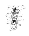
図1は、本発明の一実施形態によるブランケット引張装置を有するITM胴の断面を示す。 FIG. 1 shows a cross section of an ITM cylinder having a blanket tensioning device according to an embodiment of the present invention.
ブランケット引張装置10は、ITM胴20のギャップ22内に位置決めされる。ブランケット25(一端部のみが示される)はITM胴20の表面26に巻くことができ、ブランケット25の両端部はブランケット引張装置10により保持され引っ張られる。例えば、ブランケット25の一端部は、ブランケット引張装置10の静的バー14により保持することができ、他端部はブランケット引張装置10の動的バー12により保持することができる。
The
本発明の別の実施形態によれば、静的バー14の機能は、ITM胴20に固定される構造体(例えば、ギャップ22の片側にブランケットの一端部を取り付ける機構を含む構造体)により提供することができる。本発明の別の実施形態によれば、静的バー14を第2の動的バーで置き換えてもよい。
According to another embodiment of the present invention, the function of the
したがって、ITM胴20の全ての表面26を、ギャップ22を例外としてブランケット25で覆うことができる。ITM胴20がオフセットプリント装置内に組み込まれる場合、塗布画像の形態のインクを隣接するPIP胴からブランケット25に転写することができる。次に、ブランケット25上のインクを、ITM胴20と隣接する押圧ローラーとの間に保持される印刷媒体に転写することができる。ギャップ22の領域へ又はギャップ22の領域からインクが転写されてはならないため、ITM胴20の回転は、PIP胴の回転及び印刷媒体の移動と同期させることができる。例えば、PIP胴及びITM胴20は、同様の直径を有し、同様のレートで回転することができ、それにより、PIP胴の単一の領域がギャップ22に常に接触する。したがって、プリント装置は、画像のインクが、ギャップ22に接触するPIPの領域に決して塗布されないように構成することができる。
Therefore, the
ブランケット25の各端部には、補剛部分、端部バー、タブ、又はブランケット引張装置10の把持機構(例えば、クランプ、クリップ、フック、又は他の保持機構)により保持することができる他の特徴を設けることができる。
At each end of the
例えば、ブランケット引張装置10を操作して(例えば、外力を、例えば、ねじに加えることにより動作することができる組み込まれた作動機構により)、力を加えて、動的バー12を静的バー14から離れるように外側に回転させる(それにより、動的バー12により加えられる張力を低減する)ことができる。動的バー12及び静的バー14上のクランプを開いて(例えば、別個に)、ブランケット端部バー等のブランケット25の一端部を挿入できるようにし、次に閉じて、プランケット25の各端部を動的バー12又は静的バー14のそれぞれに把持することができる。次に、作動機構は、ブランケット引張装置10(及びギャップ22)に沿って長手方向に配置されるばねにより提供される力によって、動的バー12を静的バー14に向けて内部に付勢するトルクを加えるように動作することができる。したがって、動的バー12を静的バー14に向かって内側に付勢することにより、ブランケット25を表面26に押し付けて引っ張る張力を提供することができる。
For example, by operating the blanket tensioning device 10 (eg, with an integrated actuation mechanism that can be operated by applying an external force, eg, to a screw), a force is applied to move the
別の例として、動的バーは、第2のバー(例えば、静的バー又は第2の動的バー)に向けて又は離れるよう移動するように構成することができる。例えば、動的バーは、第2のバーに向けて又は離れるよう移動可能なように、トラック(又は複数のトラック)に沿って移動するように構成することができるか、又はガイドで制限することができる。この場合、動的バーを第2のバーから離れる方向に付勢することにより、動的バー及び第2のバーに取り付けられたブランケットに張力を提供することができる。 As another example, the dynamic bar can be configured to move toward or away from a second bar (eg, a static bar or a second dynamic bar). For example, the dynamic bar can be configured to move along the track (or tracks) so that it can move toward or away from the second bar, or can be limited by a guide Can do. In this case, urging the dynamic bar away from the second bar can provide tension to the dynamic bar and the blanket attached to the second bar.
ブランケット引張装置10の長手方向に配置されるばねは、様々な数のばね及び様々なタイプのばねを含むことができる。
The springs disposed in the longitudinal direction of the
図2Aは、本発明の一実施形態による、2つのばねを有するブランケット引張装置を示す。図2Bは、内部構造を示すために動的バーがない状態の図2Bのブランケット引張装置を示す。 FIG. 2A shows a blanket tensioning device having two springs according to an embodiment of the present invention. FIG. 2B shows the blanket tensioning device of FIG. 2B without a dynamic bar to show the internal structure.
ブランケット引張装置10はばね16を含む。2つのばね16が示されるが、一つのばね又は3つ以上のばねのいずれでも使用可能である。コイルばねが示されるが、ばね16は、任意の適切なタイプの線形ばね又は弾性要素を含むことができる。ばね16は、ブランケット引張装置10の長軸と、ブランケット引張装置10が内部に配置される溝22(図1)とに平行する向きにあることが示される。他の長手方向の向きも可能である。
The
ブランケット引張装置10のばね16は、圧縮ばねとして構成することができる。例えば、ばね16は、軸方向孔を有するシャフトを囲むコイルばねと、孔内外に移動するように構成されるプランジャーとを含むことができる。コイルばねの一端部は、シャフトの一端部を押圧することができ、別端部はプランジャーの逆端部を押圧することができる。したがって、コイルばねは、プランジャーを孔内に更に押し込むことにより圧縮することができる。次に、ばねの復元力により、プランジャーを孔から再び押し出すことができる。シャフト及び孔は、ばね16を抑制して、線形構成を維持し、曲がらないように、又はゆがまないようにすることができる。他の例では、ばね16の線形構成は、他の抑制要素により維持することができる。例えば、ばね16は、少なくとも部分的に管内に閉じ込めることができる。
The
この方法において、又は類似の方法において、ばね16の復元力が伝達機構18(本発明の一実施形態による伝達機構18の構成要素が以下で説明される)により方向を変えられ、力を動的バー12(例えば、動的バー12の内部孔内に部分的に囲まれた動的バーロッド48)に加え、それにより、動的バー12の遠位縁部を動的バー軸46の回りで静的バー14に向けて回転させるように、ばね16を圧縮することができる。
In this or similar manner, the restoring force of the
動的バー12の遠位縁部及び静的バー14の遠位縁部は、ブランケットクランプ28a及び28bをそれぞれ含む。ブランケットクランプ28bを開いて、ブランケットの一端部を挿入し、閉じて、挿入されたブランケット端部を静的バー14に対して保持することができる。同様に、ブランケットクランプ28bを開いて、ブランケットの一端部を挿入し、閉じて、挿入されたブランケット端部を動的バー12に対して保持することができる。例えば、作動ねじ30を回転することにより、ブランケットクランプ28a及び28bを開閉するとともに、ばね16を圧縮又は解放する機構を作動させることができる。例えば、ブランケットクランプ28a及び28bを開閉する機構は、作動ねじ30の回転により移動するカムに(例えば、カムフォロアにより)結合することができる。
The distal edge of the
伝達機構18はレバーリンク機構を含むことができる。
The
図3は、図2Aに示されるブランケット引張装置の伝達機構を示す。ばね16は、圧縮されているとき、二重矢印40で示されるように力を加える。力は、ばね16の各端部によりレバーリンク機構32の接続点32aに加えられる。レバーリンク機構32は旋回点36の回りを旋回することができ、レバーリンク機構32はブランケット引張装置10のフロア13(図2A及び図2B)に固定することができる。接続点32aに加えられた力は、レバーリンク機構32を、矢印44で示される方向に旋回点36の回りで回転させることができる。旋回点36の回りのレバーリンク機構32の回転は、矢印42で示される方向に接続点32b及びプルロッド34を引っ張る。プルロッド34の一端部におけるバーコネクター38は、プルロッド34を動的バー12(図2A)、例えば、動的バー12の内部孔内に保持される動的バーロッド48(図2B)に接続することができる。したがって、矢印42で示される方向でのバーコネクター38への力は、動的バー12を静的バー14に向けて引っ張り、それにより、端部が動的バー12及び静的バー14に把持されたブランケットに張力をかける。
FIG. 3 shows the transmission mechanism of the blanket tensioning device shown in FIG. 2A. When the
図3に示されるように、伝達機構18はばね16の各端部に結合されるが、他の構成も可能である。例えば、ばね(例えば、コイルばね又はガスばね)の一端部は(例えば、フロア13に接続された構造体に)固定することができ、一方で、伝達機構はばねの他端部のみに設けられる。
As shown in FIG. 3, the
図4Aは、張力がかかっていないブランケットを保持する場合の図2Aに示されるブランケット引張装置の横断面を示す。例えば、作動ねじ30の回転により作動するカム又は同様の機構は、レバーリンク機構32の回転又はプルロッド34の押圧を介して動的バー12に逆トルクを加えることができる。例えば、レバーリンク機構32は、カムフォロア(例えば、ホイールの形態)を含むことができ、それにより、レバーリンク機構は、作動ねじ30に結合されるカムの移動に応答して回転することができる。プルロッド34を押すと、バーコネクター38を動的バーロッド48に押し当てて、動的バー12を付勢して、動的バー軸46の回りで静的バー14から離れるように回転させることができる。同時に、ばね16(図2A及び図2B)等のブランケット引張装置10のばねを圧縮することができる。
FIG. 4A shows a cross section of the blanket tensioning device shown in FIG. 2A when holding an untensioned blanket. For example, a cam or similar mechanism that is actuated by rotation of the
ブランケット25の各端部(ブランケット25の端部のみが部分的に示される)は、動的バー12及び静的バー14のうちの一方に把持される。例えば、ブランケット25の一端部におけるブランケット端部バー24aは、動的バー12のブランケットクランプ28aにより保持することができる。同様に、ブランケット25の別端部におけるブランケット端部バー24bは、静的バー12のブランケットクランプ28bにより保持することができる。ブランケット25の残りの部分(大半は図示されず)は、ITM胴26(図1)の表面26に巻くことができる。したがって、静的バー14から離れるように動的バー12を回転させることにより、ブランケット25の張力を低減又は解放することができる。
Each end of the blanket 25 (only the end of the
ブランケット25を引っ張るために、動的バー12は、動的バー軸46の回りで静的バー14に向けて回転させることができる。
To pull the
図4Bは、ブランケットが引っ張られている場合の図4Aに示されるブランケット引張装置を示す。例えば、作動ねじ30を連続して回転させると、レバーリンク機構32を回転させるか、又はプルロッド34を押すように付勢するカム(又は作動機構の同様の構成要素)を移動させることができ、回転力又は押力はもはや提供されない。力がもはや提供されない場合、圧縮されたばね16(図3)の復元力又は弾性力が、レバーリンク機構32及びプルロッド34等の伝達機構18の構成要素を動作させ、動的バー12に引き寄せることができる。例えば(図3に示されるように)、プルロッド34の一端部におけるバーコネクター38は、動的バーロッド48を引き寄せることができ、それにより、動的バー12を引き寄せる。動的バー12を引き寄せると、動的バー12を動的バー軸の回りで静的バー14に向かって回転させることができる。したがって、ブランケット25の一端部にあり、動的バー12のブランケットクランプ28aにより保持されるブランケット端部バー24aは、ブランケット25の他端部における、静的バー14のブランケットクランプ28bにより保持される、ブランケット端部バー24bから離れるように引っ張ることができる。したがって、ブランケット端部バー24aをブランケット端部バー24bから離れるように引っ張ると、ITM胴26(図1)の表面26に巻かれたブランケット25に張力をかけることができる。
FIG. 4B shows the blanket tensioning device shown in FIG. 4A when the blanket is being pulled. For example, if the
ブランケット25の一端部を保持するブランケットクランプ28a又は28bは、作動機構、例えば、作動ねじ30の回転により操作される機構により操作する(例えば、開くか、又は閉じる)ことができる。
The blanket clamp 28 a or 28 b that holds one end of the
図5Aは、ブランケットクランプが閉じた状態の、本発明の一実施形態によるブランケット引張装置のブランケットクランプ操作機構を示す。図5Aは、動的バー12上のブランケットクランプ28aの操作機構を示すが、同様の操作機構は静的バー14(図4A)上でブランケットクランプ28bを操作することもできる。
FIG. 5A shows the blanket clamp operating mechanism of the blanket tensioning device according to an embodiment of the present invention with the blanket clamp closed. Although FIG. 5A shows the operating mechanism of the
動的バー12上のブランケットクランプ28aは、作動バー50の上下移動により開閉することができる。例えば、作動バー50は、カム又は同様の作動機構により作動する機構により上下に移動することができる。カムは、例えば、作動ねじ30(図2A)の回転により操作される機構により移動することができる。
The
例えば、作動バー50が上昇する場合、図5Aに示されるように、作動バー50の軌跡54は、ブランケットクランプ28aのクランプロッカーアーム51の作動ホイール52を内側に(例えば、図5Aでは右に向かい、図4Aに示される静的バー14に向けて)押すことができる。作動ホイール52を内側に押すことにより、クランプロッカーアーム51を動的バーロッド48(又は静的バー14の同様の軸)の回りで回転させて、クランプジョー56を一緒に押すことができる。したがって、ブランケット25の一端部におけるブランケット端部バー24aをブランケットクランプ28aによってしっかりと保持することができる。
For example, when the
ブランケット25を取り外し、交換する場合、ブランケットクランプ28aを操作して、ブランケット端部バー24aを解放し、別のブランケット端部バー24aを挿入可能にすることができる。
When the
図5Bは、クランプが開いた状態の図5Aのブランケットクランプ操作機構を示す。例えば、図5Bに示されるように、作動バー50が下げられると、作動バー50の軌跡54は、ブランケットクランプ28aのクランプロッカーアーム51の作動ホイール52を外側に(例えば、図5Bでは左に向かい、図4Aに示される静的バー14から離れるように)押すことができる。作動ホイール52を外側に押すことにより、クランプロッカーアーム51を動的バーロッド48(又は静的バー14の同様の軸)の回りで回転させて、クランプジョー56を分離させることができる。したがって、ブランケット25の一端部におけるブランケット端部バー24aをブランケットクランプ28aから取り出すか、又はブランケットクランプ28a内に挿入することができる。作動機構を更に作動させることにより、図5Aに示されるように、ブランケットクランプ28aを閉じることができる。
FIG. 5B shows the blanket clamp operating mechanism of FIG. 5A with the clamp open. For example, as shown in FIG. 5B, when the
同様の開閉機構が、ブランケット引張装置10(図4A)の静的バー14上のブランケットクランプ28bを操作する(開くか、又は閉じる)ことができる。
A similar opening and closing mechanism can operate (open or close) the
図6は、本発明の別の実施形態によるブランケット引張装置の別のブランケットクランプ操作機構を示す。 FIG. 6 shows another blanket clamp operating mechanism of a blanket tensioning device according to another embodiment of the present invention.
ブランケットクランプ28a及び28bは、作動アセンブリ62の動作により操作する(例えば、開閉する)ことができる。例えば、作動アセンブリ62は、作動ねじ30の回転により長手方向に並進移動(ブランケット引張装置10の長軸に沿って)することができる1つ又は複数の長手方向並進移動可能バー又はナットを含むことができる。例えば、長手方向に並進移動可能なバーは、1つ又は複数のカムを設けることができ、又はカムに設けられた1つ若しくは複数の他の構成要素を移動させることができる。カムが長手方向に並進移動すると、カムは1つ又は複数の作動装置の連携構造体(例えば、カムフォロア)と相互作用することができる。例えば、カムの長手方向位置に応答してブランケットクランプ28a又は28bの各組を開くか、又は閉じることができる。同様に、動的バー軸46の回りで動的バー12を回転させる機構は、カムの長手方向位置に従って作動することができる。
The blanket clamps 28a and 28b can be manipulated (eg, opened and closed) by operation of the
別の例として、作動アセンブリ62の動作により、1つ若しくは複数のギア、レバー、又はリンク機構アセンブリを操作することができる。
As another example, operation of the
例えば、各ブランケットクランプ28a又は28bは、ロッカーアームピボット58の回りを回転することができるクランプロッカーアーム61を含むことができる。各ブランケットクランプ28a又は28bはカム操作バー64を含むこともでき、このバーをクラアンプロッカーアーム61に押し当てて、クランプジョー56を閉じることができる。カム操作バーが、クランプロッカーアーム61への押し当てから外されると、ばね60は、クランプロッカーアーム61を逆方向に押すことができる。クランプロッカーアーム61を逆方向に押すことにより、クランプジョー56を開くことができる。クランプジョー56を開くことにより、ブランケットクランプ28a若しくは28bからブランケット端部バー24a若しくは24bをそれぞれ取り出すか、又はブランケット端部バー24a若しくは24bをブランケットクランプ28a若しくは28b内にそれぞれ挿入することを可能にすることができる。
For example, each blanket clamp 28 a or 28 b can include a
図7は、本発明の別の実施形態によるブランケット引張装置のブランケットクランプを示す。ブランケットクランプ28aは、図7では、ブランケット引張装置の動的バー12内に組み込まれて示されるが、同様のブランケットクランプをブランケット引張装置の静的バー内に組み込んでもよい。
FIG. 7 shows a blanket clamp of a blanket tensioning device according to another embodiment of the present invention. Although the
ブランケットクランプ28aのばねクリップ66は、クランプロッカーアーム51を動的アームロッド48(又は静的バーの同様の軸)の回りで回転させ、クランプジョー56を閉じるように構成される。したがって、外部から加えられる力がない場合、ばねクリップ66により、クランプジョー56を閉状態に維持して、ブランケットの端部又はブランケット端部バーを掴むか、又は把持することができる。
The
ブランケットを取り外すか、挿入するか、又は交換する場合、クランプジョー56を開き、次に、閉ざすことができる。例えば、クランプジョー56は、差動バー50の上下移動により開閉することができる。例えば、差動バー50は、カム又は同様の作動機構により作動される機構により上下移動させることができる。カムは、例えば、作動ねじ30(図2A)の回転により動作する機構により移動(例えば、長手方向並進移動)させることができる。
When the blanket is removed, inserted, or replaced, the
例えば、作動バー50は、上昇するとき、作動ホイール67を湾曲アーム68に上方に押し付けることができる。湾曲アーム68を押すことにより、動的バーロッド48(又は静的バーの同様の軸)の回りでクランプロッカーアーム51を回転させ、クランプジョー56を開くことができる。次に、作動バー50が下げられるとき、ばねクリップ66はクランプジョー56を閉じ、クランプジョー56を閉じたまま保持することができる。
For example, when the
本発明の実施形態によれば、ブランケット引張装置の他の構成も可能である。例えば、ブランケット引張装置は、2つよりも多数又は少数のばねを含むこともでき、コイルばねではないばねを含むこともできる。例えば、本発明の一実施形態は、ガスばねを有するブランケット引張装置を含むことができる。例えば、本発明の一実施形態によれば、4つのガスばねを有するブランケット引張装置は、より少数のばね又はコイルばねを有する同様のブランケット引張装置よりも、低い同等のばね定数でより大きな張力を提供することができる。 Other configurations of the blanket tensioning device are possible according to embodiments of the present invention. For example, the blanket tensioning device can include more or fewer than two springs and can include springs that are not coil springs. For example, one embodiment of the present invention can include a blanket tensioning device having a gas spring. For example, according to one embodiment of the present invention, a blanket tensioning device having four gas springs provides greater tension with a lower equivalent spring constant than a similar blanket tensioning device having fewer springs or coil springs. Can be provided.
図8は、本発明の一実施形態による、長手方向に配置された4つのガスばねを有するブランケット引張装置を示す。ブランケット引張装置70は4つのガスばね72を含む。各ガスばね72の一端部はレバーリンク機構32に接続され、他端部は静止コネクター76に接続され、それぞれの接続は旋回接続部74を介する。したがって、ガスばね72は、例えば、力が加えられた結果、又はレバーリンク機構32の回転に起因して長さが変化する場合、その向きを変更することができる。
FIG. 8 shows a blanket tensioning device having four gas springs arranged longitudinally, according to one embodiment of the present invention. The
本発明の一実施形態によるブランケット引張装置は、ブランケットの交換を可能にするように動作することができる。図9は、本発明の一実施形態によるブランケット引張装置を使用するITM胴上のブランケットを交換するプロセスを示す。ブランケット交換プロセス100は、ブランケット引張装置の構成の操作(図の対応するブロックの実線の罫線により示される)又はユーザーにより実行される動作(破線の罫線により示される)を含むことができる。例えば、図4A、図4B、及び図6に示される構成要素を参照する。
A blanket tensioning device according to an embodiment of the present invention can operate to allow for replacement of the blanket. FIG. 9 illustrates a process for replacing a blanket on an ITM cylinder using a blanket tensioning device according to one embodiment of the present invention. The
例えば、まず一方向に作動ねじ30を回転させ、次に、逆方向に回転させることによる作動機構62の動作により、ブランケット引張装置10(図9の考察の文脈の内で、ブランケット引張装置70も指すことが理解される)の一連の操作が行われ、ブランケット25の交換を容易にすることができる。例えば、1つ又は複数のカムを線形に、例えば、ブランケット引張装置10に沿って長手方向に並進移動させ、様々な連携構造体、機構、又は装置を作動させることができる。
For example, the operation of the
例えば、本発明の一実施形態によれば、作動ねじ30の回転はまず、動的バー軸46の回りで静的バー14から離れるように動的バー12を回転させ、ブランケット25の張力を解放することができる(ブロック102)。作動ねじ30を更に回転させることにより、第1の組のブランケットクランプ、例えば静的バー14上のブランケットクランプ28bを開き(ブロック104)、第1のブランケット端部バー、例えばブランケット端部バー24bを取り外せるようにすることができる(ブロック106)。作動ねじ30を更に回転させることにより、第1の組のブランケットクランプ(例えば、ブランケットクランプ28b)を閉じることができる(ブロック108)。次に、例えばITM胴を自動的又は手動のいずれかで回転させながら、ブランケットをITM胴の外面から取り外すことができる(ブロック110)。最後に、作動ねじ30を更に回転させることにより、第2の組のブランケットクランプ(例えば、動的バー12上のブランケットクランプ28a)を開き(ブロック112)、第2のブランケット端部バー、例えばブランケット端部バー24aを取り外せるようにすることができる(ブロック114)。このように、ITM胴からのブランケット25の取り外しを完了することができる。
For example, according to one embodiment of the present invention, rotation of the
この時点で、動作を逆にして、新しいブランケット25を設置することができる。新しいブランケットの第2のブランケット端部バー、例えば、ブランケット端部バー24aを、開かれた第2の組のブランケットクランプ、例えば動的バー12上のブランケットクランプ28aに挿入することができる(ブロック116)。次に、作動ねじ30を逆に回転させることにより、第2の組のブランケットクランプ(例えば、ブランケットクランプ28a)を閉じさせ(ブロック118)、それにより、第2のブランケット端部バー(例えば、ブランケット端部バー24a)を把持することができる。次に、例えばITM胴を回転させながら、新しいブランケット25をITM胴に巻くことができる(ブロック120)。次に、作動ねじ30を逆方向に更に回転させることにより、第1の組のブランケットクランプ、例えば、静的バー14上のブランケットクランプ28bを開くことができる(ブロック122)。次に、新しいブランケットの第1の端部タブ、例えば、ブランケット端部バー24bを、開かれた第1の組のブランケットクランプ、例えば、ブランケットクランプ28bに挿入することができる(ブロック124)。次に、作動ねじ30を更に回転させることにより、第1の組のブランケットクランプ(例えば、ブランケットクランプ28b)を閉じ(ブロック126)、それにより、新しいブランケットの第1の端部タブ(例えば、ブランケット端部バー24b)を把持することができる。この時点で、新しいブランケット25はITM胴に取り付けられる。次に、作動ねじ30を更に逆に回転させることにより、動的バー12を動的バー軸46の回りで静的バー14に向かって回転させ、それにより、ブランケット25に張力をかけることができる(ブロック128)。したがって、交換されたブランケット25をITM胴の回りにピンと張った状態に保持することができる。
At this point, the operation can be reversed and a
動作の順序は変更することができる。例えば、ブランケットクランプ28a及び28bを開くか、若しくは閉じる順序は変更することができ、又はブランケット28a及び28bは同時に開くか、若しくは閉じることができる。
The order of operations can be changed. For example, the order in which the blanket clamps 28a and 28b are opened or closed can be changed, or the
作動ねじ30は、ITM胴を含む印刷装置に組み込まれるか、又は関連付けられるモーターにより回転することができる。例えば、印刷装置のコントローラーは、モーターを制御して、オペレーター生成入力若しくはコマンドに応答して、又は検知される状態(例えば、ブランケット端部バーがブランケットクランプから外されているか、若しくは挿入されている状態、ブランケットがITM胴表面に巻かれているか、若しくは外されている状態)に応答して作動ねじ30を回転させることができる。代替的に、オペレーターは、適切な手動又は電動器具を使用して作動ねじ30を回転させることができる。
The
本発明の一実施形態によれば、ブランケット25を交換するのに実行される動作(例えば、ブランケット交換プロセス100のブロックで表される動作)は、1つ又は複数の電気制御される装置、例えば電子モーター又は電子磁石により実行することができる。電気制御される装置は、コントローラー、プロセッサ、又は同様のアナログ装置若しくはデジタル装置により制御することができる。例えば、コントローラー又はプロセッサは、プログラムされる命令に従って電気制御される装置を制御するように構成することができる。プログラムされる命令は、揮発性データ記憶装置若しくは不揮発性データ記憶装置、又はメモリ装置に記憶することができる。プログラムされる命令は、オペレーターに通知する命令又はオペレーター入力を待つ命令を含むことができる。 According to one embodiment of the present invention, the operations performed to replace the blanket 25 (eg, operations represented by blocks in the blanket replacement process 100) are performed by one or more electrically controlled devices, such as It can be implemented by an electronic motor or an electromagnet. The electrically controlled device can be controlled by a controller, processor, or similar analog or digital device. For example, the controller or processor can be configured to control a device that is electrically controlled in accordance with programmed instructions. The programmed instructions can be stored in a volatile data storage device, a non-volatile data storage device, or a memory device. The programmed instructions can include a command to notify the operator or a command to wait for operator input.
Claims (13)
2つの細長いブランケットホルダーであって、それぞれのブランケットホルダーの長手寸法が他方のブランケットホルダーの長手寸法と略平行し、該ブランケットホルダーのうちの少なくとも一方の少なくとも一部分が、他方のブランケットホルダーに向かって又は離れるように移動可能である、2つの細長いブランケットホルダーと、
前記長手寸法に対して長手方向に配置される少なくとも1つのばねと、
前記ばねにより及ぼされる力を、前記移動可能な部分に加えられる横方向力に変換する伝達機構であって、前記長手寸法が前記胴の軸に略平行する向きになるように該装置が前記胴に設置される場合、かつブランケットの両端部のそれぞれが前記胴の軸に略平行するように前記ブランケットホルダーのそれぞれにより保持される状態で、前記ブランケットが前記胴に巻かれる場合、前記加えられる横方向力が前記ブランケットに張力をかける、伝達機構と、
を備え、
前記ブランケットの移動可能な部分は、前記長手寸法に略平行する回転軸の回りを回転可能な回転可能バーを備え、前記横方向力はトルクを含むことを特徴とする画像転写媒体胴のブランケット引張装置。 A blanket tensioning device for an image transfer medium (ITM) cylinder,
Two elongated blanket holders, wherein the longitudinal dimension of each blanket holder is substantially parallel to the longitudinal dimension of the other blanket holder, and at least a portion of at least one of the blanket holders is directed toward the other blanket holder or Two elongated blanket holders movable away from each other;
At least one spring disposed longitudinally relative to the longitudinal dimension;
A transmission mechanism for converting a force exerted by the spring into a lateral force applied to the movable part, wherein the device is arranged so that the longitudinal dimension is oriented substantially parallel to the axis of the cylinder. And when the blanket is wound around the cylinder in a state where each end of the blanket is held by each of the blanket holders so that each of both ends of the blanket is substantially parallel to the axis of the cylinder A transmission mechanism in which a directional force tensions the blanket; and
Bei to give a,
The blanket tension of the image transfer medium cylinder , wherein the movable part of the blanket comprises a rotatable bar rotatable about a rotation axis substantially parallel to the longitudinal dimension, and the lateral force includes torque apparatus.
2つの細長いブランケットホルダーであって、それぞれのブランケットホルダーの長手寸法が他方のブランケットホルダーの長手寸法と略平行し、該ブランケットホルダーのうちの少なくとも一方の少なくとも一部分が、他方のブランケットホルダーに向かって又は離れるように移動可能である、2つの細長いブランケットホルダーと、
前記長手寸法に対して長手方向に配置される少なくとも1つのばねと、
前記ばねにより及ぼされる力を、前記移動可能な部分に加えられる横方向力に変換する伝達機構であって、前記長手寸法が前記胴の軸に略平行する向きになるように該装置が前記胴に設置される場合、かつブランケットの両端部のそれぞれが前記胴の軸に略平行するように前記ブランケットホルダーのそれぞれにより保持される状態で、前記ブランケットが前記胴に巻かれる場合、前記加えられる横方向力が前記ブランケットに張力をかける、伝達機構と、
を備え、
前記ばねは圧縮ばねを含むことを特徴とする画像転写媒体胴のブランケット引張装置。 A blanket tensioning device for an image transfer medium (ITM) cylinder,
Two elongated blanket holders, wherein the longitudinal dimension of each blanket holder is substantially parallel to the longitudinal dimension of the other blanket holder, and at least a portion of at least one of the blanket holders is directed toward the other blanket holder or Two elongated blanket holders movable away from each other;
At least one spring disposed longitudinally relative to the longitudinal dimension;
A transmission mechanism for converting a force exerted by the spring into a lateral force applied to the movable part, wherein the device is arranged so that the longitudinal dimension is oriented substantially parallel to the axis of the cylinder. And when the blanket is wound around the cylinder in a state where each end of the blanket is held by each of the blanket holders so that each of both ends of the blanket is substantially parallel to the axis of the cylinder A transmission mechanism in which a directional force tensions the blanket; and
With
The blanket tensioning device for an image transfer medium cylinder, wherein the spring includes a compression spring .
2つの細長いブランケットホルダーであって、それぞれのブランケットホルダーの長手寸法が他方のブランケットホルダーの長手寸法と略平行し、該ブランケットホルダーのうちの少なくとも一方の少なくとも一部分が、他方のブランケットホルダーに向かって又は離れるように移動可能である、2つの細長いブランケットホルダーと、
前記長手寸法に対して長手方向に配置される少なくとも1つのばねと、
前記ばねにより及ぼされる力を、前記移動可能な部分に加えられる横方向力に変換する伝達機構であって、前記長手寸法が前記胴の軸に略平行する向きになるように該装置が前記胴に設置される場合、かつブランケットの両端部のそれぞれが前記胴の軸に略平行するように前記ブランケットホルダーのそれぞれにより保持される状態で、前記ブランケットが前記胴に巻かれる場合、前記加えられる横方向力が前記ブランケットに張力をかける、伝達機構と、
を備え、
前記ばねはコイルばね又はガスばねを含むことを特徴とする画像転写媒体胴のブランケット引張装置。 A blanket tensioning device for an image transfer medium (ITM) cylinder,
Two elongated blanket holders, wherein the longitudinal dimension of each blanket holder is substantially parallel to the longitudinal dimension of the other blanket holder, and at least a portion of at least one of the blanket holders is directed toward the other blanket holder or Two elongated blanket holders movable away from each other;
At least one spring disposed longitudinally relative to the longitudinal dimension;
A transmission mechanism for converting a force exerted by the spring into a lateral force applied to the movable part, wherein the device is arranged so that the longitudinal dimension is oriented substantially parallel to the axis of the cylinder. And when the blanket is wound around the cylinder in a state where each end of the blanket is held by each of the blanket holders so that each of both ends of the blanket is substantially parallel to the axis of the cylinder A transmission mechanism in which a directional force tensions the blanket; and
With
The blanket tensioning device for an image transfer medium cylinder, wherein the spring includes a coil spring or a gas spring .
2つの細長いブランケットホルダーであって、それぞれのブランケットホルダーの長手寸法が他方のブランケットホルダーの長手寸法と略平行し、該ブランケットホルダーのうちの少なくとも一方の少なくとも一部分が、他方のブランケットホルダーに向かって又は離れるように移動可能である、2つの細長いブランケットホルダーと、
前記長手寸法に対して長手方向に配置される少なくとも1つのばねと、
前記ばねにより及ぼされる力を、前記移動可能な部分に加えられる横方向力に変換する伝達機構であって、前記長手寸法が前記胴の軸に略平行する向きになるように該装置が前記胴に設置される場合、かつブランケットの両端部のそれぞれが前記胴の軸に略平行するように前記ブランケットホルダーのそれぞれにより保持される状態で、前記ブランケットが前記胴に巻かれる場合、前記加えられる横方向力が前記ブランケットに張力をかける、伝達機構と、
を備え、
前記伝達機構は、前記ばねの作用により回転可能なレバーリンク機構を備えることを特徴とする画像転写媒体胴のブランケット引張装置。 A blanket tensioning device for an image transfer medium (ITM) cylinder,
Two elongated blanket holders, wherein the longitudinal dimension of each blanket holder is substantially parallel to the longitudinal dimension of the other blanket holder, and at least a portion of at least one of the blanket holders is directed toward the other blanket holder or Two elongated blanket holders movable away from each other;
At least one spring disposed longitudinally relative to the longitudinal dimension;
A transmission mechanism for converting a force exerted by the spring into a lateral force applied to the movable part, wherein the device is arranged so that the longitudinal dimension is oriented substantially parallel to the axis of the cylinder. And when the blanket is wound around the cylinder in a state where each end of the blanket is held by each of the blanket holders so that each of both ends of the blanket is substantially parallel to the axis of the cylinder A transmission mechanism in which a directional force tensions the blanket; and
With
The blanket tensioning device for an image transfer medium cylinder, wherein the transmission mechanism includes a lever link mechanism that is rotatable by the action of the spring .
Applications Claiming Priority (1)
| Application Number | Priority Date | Filing Date | Title |
|---|---|---|---|
| PCT/IL2011/000753 WO2013042104A1 (en) | 2011-09-25 | 2011-09-25 | Blanket tensioning device |
Publications (2)
| Publication Number | Publication Date |
|---|---|
| JP2014530128A JP2014530128A (en) | 2014-11-17 |
| JP5820077B2 true JP5820077B2 (en) | 2015-11-24 |
Family
ID=47913967
Family Applications (1)
| Application Number | Title | Priority Date | Filing Date |
|---|---|---|---|
| JP2014531371A Expired - Fee Related JP5820077B2 (en) | 2011-09-25 | 2011-09-25 | Blanket tensioning device |
Country Status (5)
| Country | Link |
|---|---|
| US (1) | US20140230673A1 (en) |
| EP (1) | EP2758242B1 (en) |
| JP (1) | JP5820077B2 (en) |
| CN (1) | CN103946024B (en) |
| WO (1) | WO2013042104A1 (en) |
Cited By (1)
| Publication number | Priority date | Publication date | Assignee | Title |
|---|---|---|---|---|
| US11768450B2 (en) | 2020-03-05 | 2023-09-26 | Fujifilm Business Innovation Corp. | Drum member and image forming apparatus |
Families Citing this family (5)
| Publication number | Priority date | Publication date | Assignee | Title |
|---|---|---|---|---|
| WO2017021960A1 (en) * | 2015-08-04 | 2017-02-09 | Kornit Digital Technologies Ltd. | Automatic hold-down pallet for textile printing |
| DE102019111510A1 (en) * | 2019-05-03 | 2020-11-05 | Koenig & Bauer Ag | Printing unit for an offset printing machine with a rubber cylinder carrying at least one rubber blanket and a method for handling a rubber blanket |
| JP7334518B2 (en) | 2019-07-19 | 2023-08-29 | 富士フイルムビジネスイノベーション株式会社 | Transfer member, transfer cylinder and image forming apparatus |
| JP7331515B2 (en) | 2019-07-19 | 2023-08-23 | 富士フイルムビジネスイノベーション株式会社 | Transfer member, transfer cylinder and image forming apparatus |
| AU2020373040A1 (en) | 2019-10-29 | 2022-06-16 | NailPro, Inc. | Automated total nail care systems, devices and methods |
Family Cites Families (13)
| Publication number | Priority date | Publication date | Assignee | Title |
|---|---|---|---|---|
| US3019729A (en) * | 1958-09-26 | 1962-02-06 | Hoe & Co R | Underside lock up device for printing plates |
| US3296673A (en) * | 1964-05-04 | 1967-01-10 | Alven D Kirkpatrick | Printing blanket edging and anchoring means |
| US3603255A (en) * | 1968-06-24 | 1971-09-07 | Wood Industries Inc | Saddle clamping device |
| US3596597A (en) * | 1969-08-08 | 1971-08-03 | Roy D Fountain | Printing press blanket anchor bar |
| US3874292A (en) * | 1973-09-17 | 1975-04-01 | Dahlgren Mfg Co | Plate clamp |
| DE2606223A1 (en) * | 1976-02-17 | 1977-08-18 | Maschf Augsburg Nuernberg Ag | DEVICE FOR TENSIONING THE RUBBER CLOTH OF AN OFFSET PRINTING MACHINE |
| IT1250045B (en) * | 1991-11-07 | 1995-03-30 | Butterfly Srl | PROCEDURE FOR THE PRODUCTION OF PLASTICIZED POLYVINYL ALCOHOL AND ITS USE FOR THE PREPARATION OF BIODEGRADABLE STARCH-BASED THERMOPLASTIC COMPOSITIONS. |
| DE4222332C2 (en) * | 1992-07-08 | 1995-04-20 | Heidelberger Druckmasch Ag | Device for fastening and changing the position of a cylinder lift |
| DE4326251C2 (en) * | 1993-08-05 | 1997-08-28 | Koenig & Bauer Albert Ag | Rubber / blanket cylinder |
| JP3446122B2 (en) * | 2000-07-12 | 2003-09-16 | 株式会社東京機械製作所 | Blanket torso |
| FR2844743B1 (en) * | 2002-09-19 | 2004-12-17 | Goss Systemes Graphiques Nante | ASSEMBLY COMPRISING A BLANKET UNIT AND A CYLINDER WITH BLANKET FASTENING DEVICE, CYLINDER, BLANKET UNIT AND OFFSET PRESS THEREOF |
| JP4699106B2 (en) * | 2005-06-24 | 2011-06-08 | 三菱重工印刷紙工機械株式会社 | Holding device |
| US7644658B2 (en) * | 2005-10-13 | 2010-01-12 | Hewlett-Packard Development Company, L.P. | Transfer drum and blanket fastening assembly |
-
2011
- 2011-09-25 WO PCT/IL2011/000753 patent/WO2013042104A1/en active Application Filing
- 2011-09-25 EP EP11872752.8A patent/EP2758242B1/en not_active Not-in-force
- 2011-09-25 CN CN201180073662.6A patent/CN103946024B/en not_active Expired - Fee Related
- 2011-09-25 US US14/347,014 patent/US20140230673A1/en not_active Abandoned
- 2011-09-25 JP JP2014531371A patent/JP5820077B2/en not_active Expired - Fee Related
Cited By (1)
| Publication number | Priority date | Publication date | Assignee | Title |
|---|---|---|---|---|
| US11768450B2 (en) | 2020-03-05 | 2023-09-26 | Fujifilm Business Innovation Corp. | Drum member and image forming apparatus |
Also Published As
| Publication number | Publication date |
|---|---|
| EP2758242A1 (en) | 2014-07-30 |
| JP2014530128A (en) | 2014-11-17 |
| US20140230673A1 (en) | 2014-08-21 |
| WO2013042104A1 (en) | 2013-03-28 |
| CN103946024A (en) | 2014-07-23 |
| EP2758242A4 (en) | 2015-07-08 |
| CN103946024B (en) | 2017-04-19 |
| EP2758242B1 (en) | 2017-08-23 |
Similar Documents
| Publication | Publication Date | Title |
|---|---|---|
| JP5820077B2 (en) | Blanket tensioning device | |
| US5218907A (en) | Plate exchange apparatus for printing press | |
| JP5734542B2 (en) | Automatic safety nails | |
| EP0411731B1 (en) | Plate-lockup apparatus for sheet-fed press | |
| US5211112A (en) | Apparatus for mounting plate on plate cylinder | |
| JP2002046251A (en) | Mechanism for drawing out cylinder using eccentric box | |
| JPS6036166A (en) | Device for varying positioning of paper delivery turn-over mechanism in paper-sheet rotary press | |
| US6386103B1 (en) | Blanket tube removal device | |
| JPH07195669A (en) | Device for handling sleeve mounted on cylinder | |
| KR20170135814A (en) | Actuating device of the articulated lever or cam type for the precise positioning of a pivotable arm | |
| JPH0528991B2 (en) | ||
| KR102145482B1 (en) | Forceps Driver Apparatus | |
| JPH08207254A (en) | Holder for chamber-type doctor | |
| EP1516728B1 (en) | Cylinder apparatus | |
| JPH0365343A (en) | Printing plate vice for printer | |
| US6250223B1 (en) | Blanket tube removal device | |
| US5553545A (en) | Plate clamping and tensioning apparatus for rotary printing press | |
| EP2070700A2 (en) | Blanket/Plate mounting apparatus | |
| KR102309185B1 (en) | Forceps Driver Apparatus | |
| JP3404192B2 (en) | Plate clamping device for rotary printing press | |
| JP3030583B2 (en) | Plate drive for rotary printing press | |
| EP1319509B1 (en) | Roller holding apparatus of printing press | |
| JPH04105943A (en) | Plate bending device for printer | |
| JP2016221842A (en) | Printing device | |
| JPH0470145B2 (en) |
Legal Events
| Date | Code | Title | Description |
|---|---|---|---|
| RD03 | Notification of appointment of power of attorney |
Free format text: JAPANESE INTERMEDIATE CODE: A7423 Effective date: 20150304 |
|
| A131 | Notification of reasons for refusal |
Free format text: JAPANESE INTERMEDIATE CODE: A131 Effective date: 20150305 |
|
| A521 | Request for written amendment filed |
Free format text: JAPANESE INTERMEDIATE CODE: A821 Effective date: 20150304 |
|
| A521 | Request for written amendment filed |
Free format text: JAPANESE INTERMEDIATE CODE: A523 Effective date: 20150528 |
|
| TRDD | Decision of grant or rejection written | ||
| A01 | Written decision to grant a patent or to grant a registration (utility model) |
Free format text: JAPANESE INTERMEDIATE CODE: A01 Effective date: 20150918 |
|
| A61 | First payment of annual fees (during grant procedure) |
Free format text: JAPANESE INTERMEDIATE CODE: A61 Effective date: 20151001 |
|
| R150 | Certificate of patent or registration of utility model |
Ref document number: 5820077 Country of ref document: JP Free format text: JAPANESE INTERMEDIATE CODE: R150 |
|
| R250 | Receipt of annual fees |
Free format text: JAPANESE INTERMEDIATE CODE: R250 |
|
| R250 | Receipt of annual fees |
Free format text: JAPANESE INTERMEDIATE CODE: R250 |
|
| LAPS | Cancellation because of no payment of annual fees | ||
| S533 | Written request for registration of change of name |
Free format text: JAPANESE INTERMEDIATE CODE: R313533 |
|
| R370 | Written measure of declining of transfer procedure |
Free format text: JAPANESE INTERMEDIATE CODE: R370 |