JP5819552B1 - Furnace wall structure of heating furnace and manufacturing method thereof - Google Patents
Furnace wall structure of heating furnace and manufacturing method thereof Download PDFInfo
- Publication number
- JP5819552B1 JP5819552B1 JP2015036171A JP2015036171A JP5819552B1 JP 5819552 B1 JP5819552 B1 JP 5819552B1 JP 2015036171 A JP2015036171 A JP 2015036171A JP 2015036171 A JP2015036171 A JP 2015036171A JP 5819552 B1 JP5819552 B1 JP 5819552B1
- Authority
- JP
- Japan
- Prior art keywords
- layer
- furnace wall
- wall structure
- furnace
- refractory
- Prior art date
- Legal status (The legal status is an assumption and is not a legal conclusion. Google has not performed a legal analysis and makes no representation as to the accuracy of the status listed.)
- Active
Links
Images
Landscapes
- Furnace Housings, Linings, Walls, And Ceilings (AREA)
Abstract
【課題】加熱炉の炉壁の強度低下を最低限に抑制するとともに、炉壁全体の熱容量を低減させることが可能な加熱炉の炉壁構造及びその製造方法を提供する。【解決手段】炉内側最内層としての耐火材料層1と、最外層としての外殻層2とを備えた加熱炉の炉壁構造10において、耐火材料層1を、最内層の位置に鉛直方向にそれぞれが積層、配設された複数の耐火・断熱煉瓦11と、最内層としての位置から最外層としての位置まで水平方向に延伸する長さを有し、それぞれが耐火・断熱煉瓦11の所定数置きに耐火・断熱煉瓦11の間に挿入、配設され、又は最上端の耐火・断熱煉瓦11上に載置、配設された少なくとも1つの耐火・断熱つなぎ煉瓦12と、から構成する。【選択図】図1The present invention provides a furnace wall structure for a heating furnace and a method for manufacturing the same, which can suppress a decrease in strength of the furnace wall of the heating furnace to a minimum and reduce the heat capacity of the entire furnace wall. In a furnace wall structure 10 of a heating furnace having a refractory material layer 1 as an innermost layer inside a furnace and an outer shell layer 2 as an outermost layer, the refractory material layer 1 is vertically arranged at the position of the innermost layer. A plurality of refractory / heat-insulating bricks 11, each having a length extending horizontally from a position as the innermost layer to a position as the outermost layer, each of which is a predetermined of the refractory / heat-insulating brick 11. It is composed of at least one refractory / heat insulating connecting brick 12 that is inserted and arranged between several refractory / heat insulating bricks 11 or placed on the uppermost refractory / heat insulating brick 11. [Selection] Figure 1
Description
本発明は、加熱炉の炉壁構造及びその製造方法に関する。 The present invention relates to a furnace wall structure of a heating furnace and a manufacturing method thereof.
加熱炉の炉壁の縦断面における炉内側最内層に位置する炉材を煉瓦で形成する場合(例えば、1600℃を超える使用温度の焼成炉の場合、最内層に位置する炉材としてセラミックファイバーを使用することができないことから、最内層に位置する炉材を煉瓦で形成する必要があり、また、炉材由来のコンタミネーションを嫌う製品を焼成する場合、前述の温度以下であっても最内層に位置する炉材を煉瓦で形成する必要がある)、炉壁の強度を保つために、バックアップとして使用する最内層以外に位置する耐火物についても一定の強度を有するものを採用し、これらを一体構造に組み立てて使用している。 When the furnace material located in the innermost layer inside the furnace in the longitudinal section of the furnace wall of the heating furnace is made of brick (for example, in the case of a firing furnace having a use temperature exceeding 1600 ° C., ceramic fiber is used as the furnace material located in the innermost layer. Because it cannot be used, it is necessary to form the furnace material located in the innermost layer with brick, and when firing products that hate contamination derived from the furnace material, the innermost layer even if it is below the above temperature In order to maintain the strength of the furnace wall, refractories located in areas other than the innermost layer used as a back-up have a certain strength. It is assembled and used as a unitary structure.
なお、一般に、炉を加熱する際の熱損失として、炉壁温度を上昇させるための熱量が10〜30%程度必要となるが、炉壁温度を上昇させるための熱量は炉壁の熱容量に依存し、炉壁の熱容量が大きくなると、炉壁温度を上昇させるための熱量(熱損失)も大きくなる。 In general, as heat loss when heating the furnace, about 10 to 30% of heat is required to raise the furnace wall temperature, but the heat quantity for raising the furnace wall temperature depends on the heat capacity of the furnace wall. However, when the heat capacity of the furnace wall increases, the amount of heat (heat loss) for increasing the furnace wall temperature also increases.
上述のような耐火物を組み合わせた一体構造を有する炉として、例えば、耐久性を向上させるとともに高熱慣性型の炉壁とするため、炉壁の耐火ライニング構成を断熱れんがと耐火れんがの2層構成とする一方、高熱慣性にすることによって本来の試験温度制御性が損なわれるため、冷却ガスの吹き込み口やガス排気口を設けて、炉内温度を制御しやすい構成とした高温曲げ試験炉が提案されている(例えば、特許文献1参照)。 As a furnace having an integrated structure combining the above-mentioned refractories, for example, in order to improve durability and to make a furnace wall of a high thermal inertia type, the refractory lining structure of the furnace wall is a two-layer structure of a heat insulating brick and a refractory brick On the other hand, because high temperature inertia reduces the original test temperature controllability, we proposed a high-temperature bending test furnace with a configuration that makes it easy to control the furnace temperature by providing a cooling gas blow-in port and a gas exhaust port. (For example, refer to Patent Document 1).
しかし、特許文献1に開示された高温曲げ試験炉の場合、耐火性は向上するものの、増大した炉壁の熱容量(熱損失)を低減するため、冷却ガスの吹き込み口やガス排気口を設ける必要があり、炉壁構造が複雑で高価になるという問題があった。
However, in the case of the high-temperature bending test furnace disclosed in
本発明は、上述の問題を解決するためになされたものであり、加熱炉の炉壁の強度低下を最低限に抑制するとともに、炉壁全体の熱容量を低減させることが可能な加熱炉の炉壁構造及びその製造方法を提供することを目的とする。 The present invention has been made in order to solve the above-described problems. A furnace for a heating furnace capable of minimizing a decrease in strength of the furnace wall of the heating furnace and reducing the heat capacity of the entire furnace wall. An object is to provide a wall structure and a manufacturing method thereof.
本発明は、上述の目的を達成するためになされたものであり、本発明によって、以下の加熱炉の炉壁構造及びその製造方法が提供される。 The present invention has been made to achieve the above-mentioned object, and the present invention provides the following furnace wall structure of a heating furnace and a method for manufacturing the same.
[1]炉壁の縦断面における炉内側最内層としての耐火材料層と、最外層としての外殻層と、前記耐火材料層と前記外殻層との間の中間層の位置に配設された断熱材料層と、を備えた、加熱炉の炉壁構造であって、前記耐火材料層は、前記最内層の位置に鉛直方向にそれぞれが積層、配設された複数の耐火・断熱煉瓦と、前記最内層としての位置から前記最外層としての位置まで水平方向に延伸する長さを有し、それぞれが前記耐火・断熱煉瓦の所定数置きに前記耐火・断熱煉瓦の間に挿入、配設された又は最上端の前記耐火・断熱煉瓦上に載置、配設された少なくとも1つの耐火・断熱つなぎ煉瓦と、から構成されてなり、前記断熱材料層は、セラミックファイバーから構成されたものである加熱炉の炉壁構造。 [1] Arranged in the longitudinal section of the furnace wall at the position of the refractory material layer as the innermost layer inside the furnace, the outer shell layer as the outermost layer, and the intermediate layer between the refractory material layer and the outer shell layer. A plurality of refractory / heat-insulating bricks, each of which is laminated and arranged in the vertical direction at the position of the innermost layer. , Having a length extending in a horizontal direction from the position as the innermost layer to the position as the outermost layer, each inserted between the fireproof and heat insulating bricks every predetermined number of the fireproof and heat insulating bricks have been or at least one fireproof adiabatic tie bricks on the fireproof thermal insulation on brick uppermost placed, arranged, Ri Na consists, the heat insulating material layer, those composed of ceramic fibers The furnace wall structure of the heating furnace.
[2]前記耐火材料層を構成する前記耐火・断熱つなぎ煉瓦と前記外殻層とを係止することによって、前記耐火材料層と前記外殻層とを一体構造とすることが可能な係止部材をさらに備えた前記[1]に記載の加熱炉の炉壁構造。 [ 2 ] Locking that enables the fireproof material layer and the outer shell layer to be integrated with each other by locking the fireproof and heat insulating connecting bricks constituting the fireproof material layer and the outer shell layer. The furnace wall structure of the heating furnace according to [1 ], further including a member.
[3]前記係止部材は、フック部材である前記[2]に記載の加熱炉の炉壁構造。
[4]前記係止部材は、金属製である前記[2]又は[3]に記載の加熱炉の炉壁構造。
[ 3 ] The furnace wall structure of the heating furnace according to [ 2 ], wherein the locking member is a hook member.
[4] The furnace wall structure of the heating furnace according to [2] or [3], wherein the locking member is made of metal.
[5]前記耐火材料層を構成する前記耐火・断熱煉瓦及び前記耐火・断熱つなぎ煉瓦は、それぞれが、隣接するもの同士の互いのずれを防止する、ずれ防止手段を有する前記[1]〜[4]のいずれか1項に記載の加熱炉の炉壁構造。 [ 5 ] The fireproof and heat insulating bricks and the fireproof and heat insulating connecting bricks that constitute the fireproof material layer each have a slip prevention means for preventing a shift between adjacent ones of the fireproof and heat insulating bricks. 4 ] The furnace wall structure of the heating furnace of any one of [ 4 ].
[6]前記ずれ防止手段は、前記耐火・断熱煉瓦及び前記耐火・断熱つなぎ煉瓦の上下面にそれぞれ形成された、互いに嵌合可能な嵌合構造である前記[5]に記載の加熱炉の炉壁構造。 [ 6 ] In the heating furnace according to [ 5 ], the slip prevention means is a fitting structure that is formed on the upper and lower surfaces of the fireproof / heat-insulating brick and the fireproof / heat-insulating brick, respectively, and can be fitted to each other. Furnace wall structure.
[7]前記嵌合構造は、凹構造及び凸構造との組み合わせである前記[6]に記載の加熱炉の炉壁構造。 [ 7 ] The furnace wall structure of the heating furnace according to [ 6 ], wherein the fitting structure is a combination of a concave structure and a convex structure.
[8]前記外殻層は、前記耐火・断熱つなぎ煉瓦の一端を支持可能な支持部材を有する前記[1]〜[7]のいずれか1項に記載の加熱炉の炉壁構造。
[9]前記支持部材は、金属製である前記[8]に記載の加熱炉の炉壁構造。
[ 8 ] The furnace wall structure of the heating furnace according to any one of [1] to [ 7 ], wherein the outer shell layer includes a support member capable of supporting one end of the fireproof and heat insulating connecting brick.
[9] The furnace wall structure of the heating furnace according to [8], wherein the support member is made of metal.
[10]前記外殻層は、金属製である前記[1]〜[9]のいずれか1項に記載の加熱炉の炉壁構造。 [10] The furnace wall structure of the heating furnace according to any one of [1] to [9], wherein the outer shell layer is made of metal.
[11]炉壁の縦断面における炉内側最内層としての耐火材料層と、最外層としての外殻層と、前記耐火材料層と前記外殻層との間の中間層の位置に配設された断熱材料層と、を備えた、加熱炉の炉壁構造を製造する方法であって、前記耐火材料層として、複数の耐火・断熱煉瓦を、前記最内層の位置に鉛直方向にそれぞれ積層、配設するとともに、前記最内層としての位置から前記最外層としての位置まで水平方向に延伸する長さを有する少なくとも1つの耐火・断熱つなぎ煉瓦を、前記耐火・断熱煉瓦の所定数置きに前記耐火・断熱煉瓦の間に挿入、配設する又は最上端の前記耐火・断熱煉瓦上に載置、配設する工程と、前記耐火材料層と前記外殻層との間の中間層の位置に、前記断熱材料層として、セラミックファイバーから構成されたものを配設する工程と、を含む加熱炉の炉壁構造の製造方法。 [ 11 ] The fireproof material layer as the innermost layer inside the furnace, the outer shell layer as the outermost layer, and the intermediate layer between the refractory material layer and the outer shell layer in the longitudinal section of the furnace wall. A method of manufacturing a furnace wall structure of a heating furnace, comprising a plurality of refractory and heat insulating bricks stacked in the vertical direction at the innermost layer as the refractory material layer , as well as arranged, said that from the previous SL position as the innermost layer at least one refractory-adiabatic connecting brick having a length extending in the horizontal direction to a position as the outermost layer, every predetermined number of the fireproof insulating bricks At the position of the intermediate layer between the refractory material layer and the outer shell layer , the step of being inserted and disposed between the refractory / heat insulating bricks, or the step of placing and arranging on the refractory / heat insulating brick at the uppermost end. The heat insulating material layer is made of ceramic fiber Method of manufacturing a furnace wall structure of a heating furnace and a step of disposing the one was.
[12]前記耐火材料層を構成する前記耐火・断熱つなぎ煉瓦と前記外殻層とを、所定の係止部材によって係止して、前記耐火材料層と前記外殻層とを一体構造とする工程をさらに含む前記[11]に記載の加熱炉の炉壁構造の製造方法。 [ 12 ] The fireproof and heat insulating connecting bricks constituting the fireproof material layer and the outer shell layer are locked by a predetermined locking member, and the fireproof material layer and the outer shell layer are integrated. The method for producing a furnace wall structure for a heating furnace according to [ 11], further including a step.
本発明によって、加熱炉の炉壁の強度低下を最低限に抑制するとともに、炉壁全体の熱容量を低減させることが可能な加熱炉の炉壁構造及びその製造方法が提供される。 According to the present invention, there is provided a furnace wall structure of a heating furnace and a manufacturing method thereof that can suppress a decrease in strength of the furnace wall of the heating furnace to a minimum and reduce the heat capacity of the entire furnace wall.
以下、本発明の実施の形態を、図面を参照しつつ具体的に説明する。 Hereinafter, embodiments of the present invention will be specifically described with reference to the drawings.
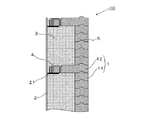
図1に示すように、本実施の形態の加熱炉の炉壁構造10は、炉壁の縦断面における炉内側最内層としての耐火材料層1と、最外層としての外殻層2とを備えている。
As shown in FIG. 1, the
耐火材料層1は、最内層の位置に鉛直方向にそれぞれが積層、配設された複数の耐火・断熱煉瓦11と、最内層としての位置から最外層としての位置まで水平方向に延伸する長さを有し、それぞれが耐火・断熱煉瓦11の所定数置きに(図1では5つ置きの場合を示す)耐火・断熱煉瓦11の間に挿入、配設され、又は最上端の耐火・断熱煉瓦11上に載置、配設された少なくとも1つの(図1では2つの場合を示す)耐火・断熱つなぎ煉瓦12と、から構成されてなるものである。なお、耐火・断熱つなぎ煉瓦12は、最上端の耐火・断熱煉瓦11上に載置されるとともに、3〜6の所定数置きに耐火・断熱煉瓦11の間に挿入、配設されることが、耐火・断熱煉瓦11を保持できる点から好ましい。
The
また、本実施の形態においては、図1に示すように、耐火材料層1と、外殻層2との間の中間層の位置に配設された断熱材料層3を、さらに備えていることが好ましい。
Moreover, in this Embodiment, as shown in FIG. 1, it further has the heat
この場合、断熱材料層3は、軽量かつ低熱伝導率であるセラミックファイバー、例えば、アルミナ、シリカから構成されたものであることが、断熱性の点から好ましい。このように構成することによって、炉としての断熱性能を保持させることができ、空隙に軽量な素材を使用することで、炉壁の熱容量を最大50%低減させることが可能となる。
In this case, it is preferable from the point of heat insulation that the heat
また、本実施の形態においては、耐火材料層1を構成する耐火・断熱つなぎ煉瓦12と外殻層2とを係止することによって、耐火材料層1と外殻層2とを一体構造とすることが可能な係止部材4をさらに備えていることが、強度を向上させる点から好ましい。
Moreover, in this Embodiment, the
この場合、係止部材4は、耐火材料層1と支持部材21を繋ぐフック状の部材であることが、耐火材料層1の倒れこみを防止できる点から好ましい。
In this case, it is preferable that the locking member 4 is a hook-shaped member that connects the
耐火材料層1を構成する耐火・断熱煉瓦11及び耐火・断熱つなぎ煉瓦12は、それぞれが、隣接するもの同士の互いのずれを防止する、ずれ防止手段5を有することが好ましい。
Each of the refractory /
ずれ防止手段5は、耐火・断熱煉瓦11及び耐火・断熱つなぎ煉瓦12の上下面にそれぞれ形成された、互いに嵌合可能な嵌合構造であることが好ましく、具体的には、嵌合構造は、図1に示すような、凹構造及び凸構造との組み合わせであることが、簡易な構成で確実なずれ防止を実現することができる点から好ましい。
The slip prevention means 5 is preferably a fitting structure that is formed on the upper and lower surfaces of the fireproof /
外殻層2は、耐火・断熱つなぎ煉瓦12の一端を支持可能な支持部材21を有することが、耐火・断熱つなぎ煉瓦12の垂れ下がりを防止できる構造である点から好ましい。
It is preferable that the
外殻層2は、例えば、SS400、SUS304等の金属製であることが支持部材21を容易に固定できる点から好ましい。
For example, the
係止部材4及び支持部材21は、それぞれSUS304、SUS316、SUS310S等の金属製であることが、熱による劣化を防止できる点から好ましい。
The locking member 4 and the
また、本実施の形態の加熱炉の炉壁構造の製造方法は、炉壁の縦断面における炉内側最内層としての耐火材料層1と、最外層としての外殻層2とを備えた、加熱炉の炉壁構造10を製造する方法であって、複数の耐火・断熱煉瓦11を、最内層の位置に鉛直方向にそれぞれ積層、配設する工程と、最内層としての位置から最外層としての位置まで水平方向に延伸する長さを有する少なくとも1つの耐火・断熱つなぎ煉瓦12を、耐火・断熱煉瓦11の所定数置きに耐火・断熱煉瓦11の間に挿入、配設する又は最上端の耐火・断熱煉瓦11上に載置、配設する工程と、を含む。
Moreover, the manufacturing method of the furnace wall structure of the heating furnace of the present embodiment includes a
また、本実施の形態においては、耐火材料層1と外殻層2との間の中間層の位置に、所定の断熱材料層3を配設する工程をさらに含むことが好ましい。
Moreover, in this Embodiment, it is preferable to further include the process of arrange | positioning the predetermined heat
また、本実施の形態においては、耐火材料層1を構成する耐火・断熱つなぎ煉瓦12と外殻層2とを、所定の係止部材4によって係止して、耐火材料層1と外殻層2とを一体構造とする工程をさらに含むことが好ましい。
Further, in the present embodiment, the refractory / heat-insulating connecting
本発明の加熱炉の炉壁構造及びその製造方法は、例えば、1600℃を超える高温の加熱炉を用いる産業分野、例えば、窯業、ガラス製造業、鉄鋼業等で有効に利用される。 The furnace wall structure of the heating furnace and the manufacturing method thereof according to the present invention are effectively used in, for example, an industrial field using a high-temperature heating furnace exceeding 1600 ° C., for example, a ceramic industry, a glass manufacturing industry, a steel industry, and the like.
1 耐火材料層
2 外殻層
3 断熱材料層
4 係止部材
5 ずれ防止手段
11 耐火・断熱煉瓦
12 耐火・断熱つなぎ煉瓦
21 支持部材
DESCRIPTION OF
Claims (12)
前記耐火材料層は、前記最内層の位置に鉛直方向にそれぞれが積層、配設された複数の耐火・断熱煉瓦と、前記最内層としての位置から前記最外層としての位置まで水平方向に延伸する長さを有し、それぞれが前記耐火・断熱煉瓦の所定数置きに前記耐火・断熱煉瓦の間に挿入、配設された又は最上端の前記耐火・断熱煉瓦上に載置、配設された少なくとも1つの耐火・断熱つなぎ煉瓦と、から構成されてなり、
前記断熱材料層は、セラミックファイバーから構成されたものである加熱炉の炉壁構造。 A heat-insulating material disposed at the position of the refractory material layer as the innermost layer inside the furnace, the outer shell layer as the outermost layer, and an intermediate layer between the refractory material layer and the outer shell layer in the longitudinal section of the furnace wall A furnace wall structure of a heating furnace comprising a layer ,
The refractory material layer extends in a horizontal direction from a position as the innermost layer to a position as the outermost layer, and a plurality of fireproof and heat-insulating bricks each stacked and arranged in the vertical direction at the position of the innermost layer. Each of which has a length, and is inserted and arranged between the fireproof and heat insulating bricks every predetermined number of the fireproof and heat insulating bricks, or placed and disposed on the fireproof and heat insulating bricks at the uppermost end. at least one fireproof adiabatic tie bricks, Ri Na consist,
The heat insulating material layer is a furnace wall structure of a heating furnace made of ceramic fibers .
前記耐火材料層として、複数の耐火・断熱煉瓦を、前記最内層の位置に鉛直方向にそれぞれ積層、配設するとともに、前記最内層としての位置から前記最外層としての位置まで水平方向に延伸する長さを有する少なくとも1つの耐火・断熱つなぎ煉瓦を、前記耐火・断熱煉瓦の所定数置きに前記耐火・断熱煉瓦の間に挿入、配設する又は最上端の前記耐火・断熱煉瓦上に載置、配設する工程と、
前記耐火材料層と前記外殻層との間の中間層の位置に、前記断熱材料層として、セラミックファイバーから構成されたものを配設する工程と、を含む加熱炉の炉壁構造の製造方法。 A heat-insulating material disposed at the position of the refractory material layer as the innermost layer inside the furnace, the outer shell layer as the outermost layer, and an intermediate layer between the refractory material layer and the outer shell layer in the longitudinal section of the furnace wall A method of manufacturing a furnace wall structure of a heating furnace comprising a layer ,
As the refractory material layer, stretching the plurality of fireproof insulating bricks, each vertically stacked on the position of the innermost layer, as well as arranged in a horizontal direction to a position as a pre-Symbol the outermost layer from the position of the innermost layer At least one refractory / heat-insulating connecting brick having a length of Placing and arranging; and
A method of manufacturing a furnace wall structure of a heating furnace, including a step of disposing a layer made of ceramic fiber as the heat insulating material layer at a position of an intermediate layer between the refractory material layer and the outer shell layer .
Priority Applications (1)
| Application Number | Priority Date | Filing Date | Title |
|---|---|---|---|
| JP2015036171A JP5819552B1 (en) | 2015-02-26 | 2015-02-26 | Furnace wall structure of heating furnace and manufacturing method thereof |
Applications Claiming Priority (1)
| Application Number | Priority Date | Filing Date | Title |
|---|---|---|---|
| JP2015036171A JP5819552B1 (en) | 2015-02-26 | 2015-02-26 | Furnace wall structure of heating furnace and manufacturing method thereof |
Publications (2)
| Publication Number | Publication Date |
|---|---|
| JP5819552B1 true JP5819552B1 (en) | 2015-11-24 |
| JP2016156595A JP2016156595A (en) | 2016-09-01 |
Family
ID=54610912
Family Applications (1)
| Application Number | Title | Priority Date | Filing Date |
|---|---|---|---|
| JP2015036171A Active JP5819552B1 (en) | 2015-02-26 | 2015-02-26 | Furnace wall structure of heating furnace and manufacturing method thereof |
Country Status (1)
| Country | Link |
|---|---|
| JP (1) | JP5819552B1 (en) |
Cited By (2)
| Publication number | Priority date | Publication date | Assignee | Title |
|---|---|---|---|---|
| CN112985072A (en) * | 2021-03-15 | 2021-06-18 | 东台市港泰耐火材料有限公司 | Refractory heat-insulating brick and preparation process thereof |
| CN116608696A (en) * | 2023-06-15 | 2023-08-18 | 广西柳钢新材料科技有限公司 | Masonry method of C-type double-chamber kiln inner ring masonry structure |
Families Citing this family (2)
| Publication number | Priority date | Publication date | Assignee | Title |
|---|---|---|---|---|
| EP3416920B1 (en) * | 2016-02-18 | 2024-04-03 | Fosbel, Inc. | Glass furnace regenerators formed of one-piece load-bearing wall blocks |
| CN111998380B (en) * | 2020-07-30 | 2024-06-25 | 宜兴市鹏业耐火制品有限公司 | Refractory layer closing-in structure for natural gas sulfur recovery device boiler |
Citations (1)
| Publication number | Priority date | Publication date | Assignee | Title |
|---|---|---|---|---|
| JP2010236740A (en) * | 2009-03-31 | 2010-10-21 | Akechi Ceramics Co Ltd | Furnace structure |
-
2015
- 2015-02-26 JP JP2015036171A patent/JP5819552B1/en active Active
Patent Citations (1)
| Publication number | Priority date | Publication date | Assignee | Title |
|---|---|---|---|---|
| JP2010236740A (en) * | 2009-03-31 | 2010-10-21 | Akechi Ceramics Co Ltd | Furnace structure |
Cited By (2)
| Publication number | Priority date | Publication date | Assignee | Title |
|---|---|---|---|---|
| CN112985072A (en) * | 2021-03-15 | 2021-06-18 | 东台市港泰耐火材料有限公司 | Refractory heat-insulating brick and preparation process thereof |
| CN116608696A (en) * | 2023-06-15 | 2023-08-18 | 广西柳钢新材料科技有限公司 | Masonry method of C-type double-chamber kiln inner ring masonry structure |
Also Published As
| Publication number | Publication date |
|---|---|
| JP2016156595A (en) | 2016-09-01 |
Similar Documents
| Publication | Publication Date | Title |
|---|---|---|
| JP5819552B1 (en) | Furnace wall structure of heating furnace and manufacturing method thereof | |
| CN204612483U (en) | There is the refractory brick of composite adiabatic structure | |
| US3914100A (en) | Pipe protective covering | |
| JP5851404B2 (en) | Osako ceiling structure | |
| US7677007B2 (en) | Interlocking insulating firebrick | |
| EP3058300B1 (en) | Burner port block assembly | |
| JP3173375U (en) | Multi-layer heating furnace | |
| JP5953414B1 (en) | Furnace wall structure | |
| TWI294956B (en) | Industrial kiln | |
| US2929343A (en) | Basic arch for reverberatory furnace | |
| US4170856A (en) | Metal encased refractory brick | |
| EP2851640B1 (en) | Refractory ceramic lining brick and corresponding refractory ceramic lining | |
| CN218955476U (en) | Special-shaped refractory brick and kiln lining structure | |
| CN101535446A (en) | Coke oven wall brickwork structure | |
| EP3254044B1 (en) | Segmented refractory rider arch | |
| CN108800941B (en) | A kind of biting connecions hanging furnace top refractory brick construction method | |
| CN217737868U (en) | Rotary kiln lining brick masonry structure | |
| JP6554940B2 (en) | Thermal storage brickwork structure of coke oven thermal storage room | |
| CS270436B2 (en) | Furnace's arch | |
| CN217737216U (en) | Anti-erosion mullite refractory brick for chemical incinerator | |
| US1612795A (en) | Fire arch for furnaces | |
| JP6742659B1 (en) | Construction and construction method of construction | |
| JP4558442B2 (en) | Burner tile | |
| RU2056026C1 (en) | Thermal insulation of vertical furnace bottom pipes | |
| JPS60287A (en) | Composite element for ceiling of furnace |
Legal Events
| Date | Code | Title | Description |
|---|---|---|---|
| TRDD | Decision of grant or rejection written | ||
| A01 | Written decision to grant a patent or to grant a registration (utility model) |
Free format text: JAPANESE INTERMEDIATE CODE: A01 Effective date: 20150901 |
|
| A61 | First payment of annual fees (during grant procedure) |
Free format text: JAPANESE INTERMEDIATE CODE: A61 Effective date: 20150930 |
|
| R150 | Certificate of patent or registration of utility model |
Ref document number: 5819552 Country of ref document: JP Free format text: JAPANESE INTERMEDIATE CODE: R150 |
|
| R250 | Receipt of annual fees |
Free format text: JAPANESE INTERMEDIATE CODE: R250 |
|
| R250 | Receipt of annual fees |
Free format text: JAPANESE INTERMEDIATE CODE: R250 |
|
| R250 | Receipt of annual fees |
Free format text: JAPANESE INTERMEDIATE CODE: R250 |
|
| R250 | Receipt of annual fees |
Free format text: JAPANESE INTERMEDIATE CODE: R250 |
|
| R250 | Receipt of annual fees |
Free format text: JAPANESE INTERMEDIATE CODE: R250 |
|
| R250 | Receipt of annual fees |
Free format text: JAPANESE INTERMEDIATE CODE: R250 |
|
| R250 | Receipt of annual fees |
Free format text: JAPANESE INTERMEDIATE CODE: R250 |
|
| R250 | Receipt of annual fees |
Free format text: JAPANESE INTERMEDIATE CODE: R250 |