JP5815537B2 - 2-part intravascular anastomosis connector - Google Patents
2-part intravascular anastomosis connector Download PDFInfo
- Publication number
- JP5815537B2 JP5815537B2 JP2012533187A JP2012533187A JP5815537B2 JP 5815537 B2 JP5815537 B2 JP 5815537B2 JP 2012533187 A JP2012533187 A JP 2012533187A JP 2012533187 A JP2012533187 A JP 2012533187A JP 5815537 B2 JP5815537 B2 JP 5815537B2
- Authority
- JP
- Japan
- Prior art keywords
- anastomotic connector
- diameter portion
- connector according
- supply conduit
- conduit
- Prior art date
- Legal status (The legal status is an assumption and is not a legal conclusion. Google has not performed a legal analysis and makes no representation as to the accuracy of the status listed.)
- Expired - Fee Related
Links
Images


Classifications
-
- A—HUMAN NECESSITIES
- A61—MEDICAL OR VETERINARY SCIENCE; HYGIENE
- A61M—DEVICES FOR INTRODUCING MEDIA INTO, OR ONTO, THE BODY; DEVICES FOR TRANSDUCING BODY MEDIA OR FOR TAKING MEDIA FROM THE BODY; DEVICES FOR PRODUCING OR ENDING SLEEP OR STUPOR
- A61M1/00—Suction or pumping devices for medical purposes; Devices for carrying-off, for treatment of, or for carrying-over, body-liquids; Drainage systems
- A61M1/36—Other treatment of blood in a by-pass of the natural circulatory system, e.g. temperature adaptation, irradiation ; Extra-corporeal blood circuits
- A61M1/3621—Extra-corporeal blood circuits
- A61M1/3653—Interfaces between patient blood circulation and extra-corporal blood circuit
- A61M1/3655—Arterio-venous shunts or fistulae
-
- A—HUMAN NECESSITIES
- A61—MEDICAL OR VETERINARY SCIENCE; HYGIENE
- A61F—FILTERS IMPLANTABLE INTO BLOOD VESSELS; PROSTHESES; DEVICES PROVIDING PATENCY TO, OR PREVENTING COLLAPSING OF, TUBULAR STRUCTURES OF THE BODY, e.g. STENTS; ORTHOPAEDIC, NURSING OR CONTRACEPTIVE DEVICES; FOMENTATION; TREATMENT OR PROTECTION OF EYES OR EARS; BANDAGES, DRESSINGS OR ABSORBENT PADS; FIRST-AID KITS
- A61F2/00—Filters implantable into blood vessels; Prostheses, i.e. artificial substitutes or replacements for parts of the body; Appliances for connecting them with the body; Devices providing patency to, or preventing collapsing of, tubular structures of the body, e.g. stents
- A61F2/02—Prostheses implantable into the body
- A61F2/04—Hollow or tubular parts of organs, e.g. bladders, tracheae, bronchi or bile ducts
- A61F2/06—Blood vessels
- A61F2/064—Blood vessels with special features to facilitate anastomotic coupling
Description
[関連出願の相互参照]
本出願は、2009年10月8日に出願された米国特許仮出願第61/249,704号(係属中)の優先権を主張するものであり、その開示を参照により本明細書に組み込む。
[Cross-reference of related applications]
This application claims priority from US Provisional Application No. 61 / 249,704 (pending), filed Oct. 8, 2009, the disclosure of which is incorporated herein by reference.
本発明は、一般に、血管コネクタ装置、およびその血管コネクタ装置を用いる方法に関する。より詳細には、本発明は吻合コネクタおよび送達方法に関する。 The present invention generally relates to a vascular connector device and a method of using the vascular connector device. More particularly, the present invention relates to an anastomotic connector and delivery method.
人体の循環系は、代謝物質、ホルモン、および細胞廃棄物などの化学物質を含む血液を細胞から、及び細胞へ移送する。器官系は、心臓、血液、および血管網を含む。静脈は、血液を心臓に向けて搬送する管であり、動脈は心臓から血液を送り出す。ヒトの心臓は、2つの心房腔と2つの心室腔からなる。心房腔は静脈から血液を受け取り、またより大きな筋肉壁を含む心室腔は、心臓から血液をポンプ送りする。血液の動きは以下のようになる。血液は、上大静脈または下大静脈から右心房に入り、右心室へと進む。右心室から、血液は、肺動脈を経由して肺へとポンプ送りされ酸素化される。血液が酸素化されると、血液は、肺静脈を経由して左心房に入ることにより心臓に戻り、左心室へと流入する。最後に、血液は、左心室からポンプ送りされて、大動脈および血管網に入る。 The human circulatory system transports blood, including metabolites, hormones, and chemicals such as cell waste, from and to cells. The organ system includes the heart, blood, and vascular network. Veins are tubes that carry blood toward the heart, and arteries pump blood from the heart. The human heart consists of two atrial chambers and two ventricular chambers. The atrial cavity receives blood from the veins, and the ventricular cavity, which includes the larger muscle wall, pumps blood from the heart. The blood movement is as follows. Blood enters the right atrium from the superior or inferior vena cava and proceeds to the right ventricle. From the right ventricle, blood is pumped and oxygenated through the pulmonary artery into the lung. When blood is oxygenated, it returns to the heart by entering the left atrium via the pulmonary vein and flows into the left ventricle. Finally, blood is pumped from the left ventricle and enters the aorta and vascular network.
いくつかの場合では、血管網と流体連通を維持することが必要になる。例えば、循環補助システムは、血液を、血管網を通してポンプ送りするのを助けるために使用することができ、それによりうっ血性心不全(一般に心疾患と呼ばれる)に関連する症状が軽減される。循環補助システムのポンプは、流入および流出カニューレを含む。流入カニューレは、心臓の左心房をポンプに接続し、流出カニューレは、ポンプを動脈系に接続することが多い。 In some cases it will be necessary to maintain fluid communication with the vascular network. For example, the circulatory assist system can be used to help pump blood through the vascular network, thereby reducing symptoms associated with congestive heart failure (commonly referred to as heart disease). The pump of the circulatory assist system includes inflow and outflow cannulas. The inflow cannula often connects the left atrium of the heart to the pump, and the outflow cannula often connects the pump to the arterial system.
循環補助装置を早期に設けることは、心臓の負荷を軽減し、かつ低下する左心室の機能を有する患者でうっ血性心不全のさらなる進行を妨げる可能性がある。しかし、循環補助装置から最も利益が得られるはずの患者は、外科手術の侵襲性に対して脆弱過ぎることが多い。したがって、外科的手技の侵襲性を減少させる装置および手順が引き続き求められている。例えば、最小の侵襲性で血管構造へと送達され、かつ固定することができ、補助装置に取り付けることもできる装置を有することは有利なはずである。 Providing circulatory assist devices early may reduce the load on the heart and prevent further progression of congestive heart failure in patients with reduced left ventricular function. However, patients who would benefit most from circulatory assist devices are often too vulnerable to surgical invasiveness. Accordingly, there is a continuing need for devices and procedures that reduce the invasiveness of surgical procedures. For example, it would be advantageous to have a device that can be delivered and fixed to the vasculature with minimal invasiveness and that can also be attached to an auxiliary device.
例示的な一実施形態では、本発明は、血管導管および供給導管を含む血管内コンポーネントと、カニューレコンポーネントとを備える吻合コネクタを対象とする。血管導管は、血管構造内に存在するように構成された第1および第2の端部を有する。供給導管は、近位端および遠位端を有しており、遠位端は、第1の端部と第2の端部の間で血管導管に対して流体連通するように接続される。近位端および遠位端を同様に含むカニューレコンポーネントが、供給導管により受け入れられる。 In one exemplary embodiment, the present invention is directed to an anastomotic connector comprising an intravascular component including a vascular conduit and a supply conduit, and a cannula component. The vascular conduit has first and second ends configured to reside within the vascular structure. The supply conduit has a proximal end and a distal end, the distal end being connected in fluid communication with the vascular conduit between the first end and the second end. A cannula component that also includes a proximal end and a distal end is received by the supply conduit.
例示の実施形態の他の態様では、カニューレコンポーネントの近位端は、補助装置に接続されるように構成されたハブをさらに含む。 In other aspects of the exemplary embodiment, the proximal end of the cannula component further includes a hub configured to be connected to an auxiliary device.
図1は、移植された循環補助システム10を示す。例示のために、右心房16、左心房18、右心室20、および左心室22を有する患者14の心臓12を含む、ある解剖学的構造が示されている。左および右鎖骨下静脈24、26、および左および右頸静脈28、30からの血液は、上大静脈32を通って右心房16に入るが、体の下部からの血液は、下大静脈34を通って右心房16に入る。血液は、右心房16から右心室20に、さらに肺(図示せず)にポンプ送りされて酸素化される。肺から戻った血液は、肺静脈36から左心房18に入り、次いで、左心室22へとポンプ送りされる。左心室22を出た血液は、大動脈38に入り、かつ左鎖骨下動脈40、左総頸動脈42、および右鎖骨下動脈46および右総頸動脈48を含む腕頭動脈44に入る。
FIG. 1 shows an implanted circulatory assist system 10. For illustrative purposes, an anatomical structure is shown including the heart 12 of a
移植された循環補助システム10に関して、可撓性のあるカニューレ本体50が、左心房18内から心房内中隔52を通り、経皮的に右鎖骨下静脈26の血管アクセス部位54へと延びる。可撓性のあるカニューレ本体50は、移植可能なポンプ58の入力ポート56に取り付けられる。血管内吻合コネクタ60は、移植可能なポンプ58の出力ポート62を、右鎖骨下動脈46などの適切な動脈に接続する。医師は、移植可能なポンプ58を、血管アクセス部位54の近くに位置するポンプポケット64中に皮下的に、また任意選択で、筋肉下に配置することができるが、あるいはポンプ58を外部で維持することもできる。
With respect to the implanted circulatory assist system 10, a
図2は、血管導管66と、血管導管66と共に分岐継手70を形成する供給導管68とからなる血管内コンポーネント65を含む血管内吻合コネクタ60の分解図を示している。分岐継手70は、可撓性を有すると共に血管の自然の撓み性を再現すべきであり、また血管内吻合コネクタ60の意図された用途、および局所的な解剖学的構造に応じて、約5°から約90°(直角)まで変わりうる角度を形成する。
FIG. 2 shows an exploded view of an
血管導管66の構成は、拡張可能な材料からなる補強構造72を含むことができる。拡張可能な材料は、ニッケルチタン(NiTi)などの超弾性および自己拡張性のものとすることができる。代替的には、ニッケルコバルト(NiCo)、またはコバルトクロム(CrCo)などのバルーン拡張可能材料を使用することができる。その場合、補強構造72を、多孔質のポリマー材料のカバー74内に封入することができて、内皮細胞の移行を可能にし、かつ血管導管66を血管壁に固定できるようにする。適切なカバーは、延伸ポリテトラフルオロエチレン(ePTFE)、織られたポリエステル、ベロア、またはDACRON(ダクロン)ブランドの合成ポリエステル織物を含むことができる。
The configuration of the
必ずしも必要ではないが、血管導管66は、より広い範囲の血管直径に適合するように、かつ血管導管66と血管の間で滑らかに流れる遷移部を提供するために外側に広げることができる(参照符号75で示す)。
Although not necessary, the
供給導管68はまた、多孔質のポリマー材料から構成することができる。いくつかの実施形態では、血管導管66の壁厚は、供給導管68の壁厚よりも薄くすることができる。血管導管66は血管内に移植され、また血流の障害とならないようにその輪郭を最小にすべきであるため、このようにすることはその逆の場合よりも好ましい。ただし、血管導管66と供給導管68の壁は共に、以下でより詳細に述べる方法で、血管内コンポーネント65を折り畳み、かつ送達する可撓性を保証するように最小の厚さで構成すべきである。
The
図で示すように、供給導管68の構成は、大径部76と、大径部76に対して遠位にある小径部78とを含むことができる。小径部78の長さは、血管の壁厚を少なくとも満たすべきであるが、あるいはいくつかの実施形態では、血管の壁厚をわずかに超えることができる。血管内コンポーネント65が、小容積の血管中へと挿入される場合、供給導管68の小径部78は、血管導管66の管腔の直径にほぼ等しい直径の管腔を有するように構成することができ、血管に入る血液量を抑えて血管の自然な容量を超えないようにする。大径部76は、カニューレコンポーネント80の外径を受け入れるために、かつその相対的な動きを可能にするのに十分な内径で構成すべきである。
As shown, the configuration of the
大径部76と小径部78との間の遷移部82は、以下でより詳細に述べる方法で、カニューレコンポーネント80に対する強制停止部として働く。
The
供給導管68中へと送られるカニューレコンポーネント80は、供給導管68に対する構造的安定性と、ポンプ58(図1)または他の補助装置に接続するための近位のハブ84とを共に提供する。カニューレコンポーネント80は、熱可塑性(例えば、ポリウレタンまたはPEBAX)材料もしくは熱硬化性(例えば、シリコーン)材料など、「軟質」であり、かつ高い伸び特性を有する低デュロメータ(例えば、ショアA)の材料から構成することができる。
A
供給導管68に関して上記で述べたように、カニューレコンポーネント80はまた、遷移部90で分離された大径部86および小径部88を含むことができる。大径部86、小径部88、および遷移部90は、供給導管68の対応する部分76、78、82の寸法に対して、供給導管68とカニューレコンポーネント80の間で適正に、かつしっかりと嵌合することを保証するような寸法で構成すべきである。カニューレコンポーネント80の小径部88はまた、血管内コンポーネント65の分岐継手70の望ましい角度を再現するようにも構成すべきである。
As described above with respect to supply
いくつかの実施形態では、小径部88は、NiTi、ステンレス鋼、または他の同様な生体適合性のある金属から構成された金属支持体92を含むことができる。金属支持体92は、カニューレコンポーネント80が供給導管68に嵌め合わされたときに加えられる外力により、小径部88がつぶれないようにするのを支援する。金属支持体92は、小径部88の壁を構成する多孔質のポリマー材料内に封入された(図2で示す)編組み、または(図3Fで示す)コイルとして形成することができる。大径部86もまた、同様な方法で構成され、かつねじり抵抗を提供する金属支持体94により支持されうる。
In some embodiments, the
カニューレコンポーネント80のハブ84は、供給導管68から近位方向に延びており、医師が、特定の個人の解剖学的構造に適合させるために、血管内吻合コネクタ60の全体長を調整できるように長さを変えることができる。調整可能なハブ84を構成する一方法は、長手方向に間隔を空けた環状部材(図示せず)を成形することを含む。長手方向の間隔は、ポンプ58(図1)の出口62(図1)を収容するために十分なものとすることができる。したがって、医師は、適切な長さで、かつ連続する環状部材の間でハブ84を切断することができる。
The
図3A〜3Fは、血管内吻合コネクタ60を使用する例示的な一方法を示している。この方法に対する準備として、医師は、血管内コンポーネント65を送達システム95中に事前に挿入するが、送達システム95は、図示のように送達シース96および送達カテーテル97を含む。折り畳む例示的な一方法は、送達カテーテル97が、供給導管68を通って送られ、血管導管66の第2の端部100から遠位方向に出た後、血管導管66の第1の端部98を供給導管68の周囲に巻き付けることを含む。送達カテーテル97を有する巻き付けられた血管内吻合コネクタ60は、次いで、送達シース96中に挿入される。いくつかの実施形態では、具体的には示していないが、送達カテーテル97は、血管導管66の内面に接触するように、かつ送達中に血管内コンポーネント65の位置の安定化を助けるために、少なくともわずかに膨張するバルーン部分を含むことができる。
3A-3F illustrate one exemplary method of using the intravascular
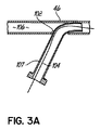
血管内吻合コネクタ60を使用する例示的な方法において、図3Aは、ここでは右鎖骨下動脈46として示されている血管壁の切開部102を示している。医師は、次いで、ガイドワイヤ104を、切開部102を通して右鎖骨下動脈46の管腔106内へと進ませる。導入器107がガイドワイヤ104上で後部から挿入されて、出血を低減または阻止しながら切開部102を通り動脈46へのアクセスを維持する。適切な導入器は、米国インディアナ州ブルーミントンのCook Medical(クックメディカル社)によるCHECK−FLO PERFORMERなど、市販のものを含むことができるが、あるいは個々の必要性に合わせてカスタム化することもできる。
In an exemplary method using an intravascular
図3Bでは、送達システム95を備える折り畳まれた血管内コンポーネント65が、次いで、ガイドワイヤ104上に後部から挿入され、導入器107を通り、送達シース96が導入器107の遠位端に対してちょうど遠位に配置されるまで動脈46中へと前進する。ガイドワイヤ104は、送達カテーテル97の管腔を通って同軸に延びる。
In FIG. 3B, the folded
送達シース96および血管内コンポーネント65が適正に配置されると、医師は、送達シース96を部分的に後退させ、血管導管66の第2の端部100を解放し、展開する。次いで、続けて後退させることにより、血管導管66の第1の端部98が解放され、展開されるようになる。代替的に、医師は、血管内コンポーネント65を備える送達カテーテル97を送達シース96から遠位方向に、かつ動脈46の管腔106内へと前進させることもできる。
Once the
図3Cは、右鎖骨下動脈46の管腔106内に展開された血管導管66を示す。補強構造72(図2)が自己拡張性材料から構成される実施形態では、血管導管66は、解放されると自動的に拡張して、右鎖骨下動脈46の管腔106の容積を満たすことになる。図3Cはさらに、90°未満の角度を有する分岐継手を示している。
FIG. 3C shows the
右鎖骨下動脈46内の血管導管66の位置は、血管導管66が切開部102に対して確実に密封を行うように、送達シース96、供給導管68、および/または送達カテーテル97を動かすことにより操作することができる。送達シース96および送達カテーテル97を、次いで、血管内コンポーネント65から後退させるが、導入器107およびガイドワイヤ104は、配置された状態で残ることができる。
The position of the
血管導管66がバルーン拡張可能材料から構成される実施形態では、図3D〜3Fを参照して説明する方法で、血管導管66を拡張するために従来のバルーンカテーテル108(図3D)を使用することができる。
In embodiments where the
図3Dは、第2の切開部位112に配置された導入器111を通り、血管導管66の管腔へと第2のガイドワイヤ110に沿ってバルーンカテーテル108を送る様子を示している。導入器111は、前に述べた導入器107(図3A)と同様のものとすることができる。図示のように、第2の切開部位112は、右または左大腿動脈114、115に位置することができ、また中隔を横断する可撓性のあるカニューレ本体50を移植するために、心房内中隔52(図1)に経皮的にアクセスするのに使用された大腿静脈アクセス部位(図示せず)の近傍にある。経皮的にアクセスし、移植する一方法は、米国特許出願第12/256,911号でより詳細に述べられており、その開示全体を参照により本明細書に組み込む。プラグ116は、血液が失われるのを阻止するために、かつ可撓性のあるカニューレ本体50がポンプ58(図1)に流体連通するように接続されるまで、可撓性のあるカニューレ本体50の近位端に一時的に配置することができる。
FIG. 3D shows the
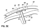
第2のガイドワイヤ110は、第2の切開部位112から、下行大動脈118を上昇し、腕頭動脈44を通り右鎖骨下動脈46へと送られる。次いで、ガイドカテーテル120は、血管導管66のすぐ前の位置へと第2のガイドワイヤ110上で送られうる。バルーンカテーテル108は、次いで、ガイドカテーテル120から遠位方向に延びるまで、かつ図3Eで示すように、そのバルーン部分122が血管導管66の管腔内に存在するように、第2のガイドワイヤ110上でガイドカテーテル120を通って前進する。
The
バルーンカテーテル108が適切に配置されると、医師は、次いで、バルーン部分122を膨張させることができ、バルーン部分122は、血管導管66の内面に接触し、かつ補強構造72(図2)を拡張させることになる。その結果、血管導管66は、右鎖骨下動脈46の管腔106(図3A)を満たす。バルーンカテーテル108のバルーン部分122を、次いで、収縮させて、血管内コンポーネント65から後退させることができる。ガイドカテーテル120および第2のガイドワイヤ110もまた、後退させることができる。
Once the
具体的に示していないが、バルーンカテーテル108を送る代替方法は、例えば、右橈骨動脈近くの切開部から、または血管内コンポーネント65へのアクセス可能性を提供する任意の他の血管構造からのものとすることができる。
Although not specifically shown, alternative methods of delivering the
図3Fは、次いで、カニューレコンポーネント80を、血管内吻合コネクタ60の供給導管68中へ前進させる様子を示している。カニューレコンポーネント80は、遷移部90がカニューレコンポーネント80に対する強制停止部(positive stop)となる供給導管68の遷移部82と接触し、かつその上に配置されるまで前進する。
FIG. 3F then shows the
図4は、組み立てられた装置における1つまたは複数のシールリングによるカニューレコンポーネント80と供給導管68の間の締まり嵌めを示している。図示のように、カニューレコンポーネント80の小径部88は、遠位のシールリング124と、近位のシールリング126とを含む。近位のシールリング126は、供給導管68とカニューレコンポーネント80の間の締まり嵌めを提供することができる。遠位のシールリング124は、分岐継手70において締まり嵌めを提供し、血管導管66とカニューレコンポーネント80との間の滑らかな流体的遷移を保証する。カニューレコンポーネント80の小径部88が、供給導管68の小径部78の中に滑らせて挿入されると、右鎖骨下動脈46の壁は、遠位のシールリング124により伸張される。この伸張により半径方向に圧縮されて、切開部102で血管内吻合コネクタ60を密封することが促進される。
FIG. 4 shows an interference fit between
医師は、適切な長さにハブ84(図2)を切断し、かつそれをポンプ58(図1)の流出ポート62(図1)に接続することにより手順を完了することができる。プラグ116(図3D)は、可撓性のあるカニューレ本体50(図1)の近位端から取り外され、したがって、可撓性のあるカニューレ本体50(図1)は、ポンプ58(図1)の流入ポート56(図1)に接続されうる。 The physician can complete the procedure by cutting the hub 84 (FIG. 2) to the appropriate length and connecting it to the outflow port 62 (FIG. 1) of the pump 58 (FIG. 1). Plug 116 (FIG. 3D) is removed from the proximal end of flexible cannula body 50 (FIG. 1), and therefore flexible cannula body 50 (FIG. 1) is connected to pump 58 (FIG. 1). Inflow port 56 (FIG. 1).
図1で示したように、完了した血液の流れは以下のようになる。すなわち、酸素化された血液は、左心房18から自然な経路を介して左心室22へと進み大動脈38へと移動することになる。大動脈38から、血液は、左鎖骨下動脈40、左総頸動脈42、および腕頭動脈44へと進む。酸素化された血液はまた、左心房18から可撓性のあるカニューレ本体50に入り、可撓性のあるカニューレ本体50の管腔を通ってポンプ58へと移動することになる。ポンプ58は、血液を血管内吻合コネクタ60のカニューレコンポーネント80に、さらに右鎖骨下動脈46へと能動的にポンプ送りする。ここから、血液は、血管網の残りの部分へと送られる。
As shown in FIG. 1, the completed blood flow is as follows. That is, the oxygenated blood travels from the
本発明は、様々な好ましい実施形態の説明により示され、かつこれらの諸実施形態が何らかの細部で記述されているが、本出願人は、添付の特許請求の範囲をこのような細部に制限すること、または何らかの形で限定することを意図していない。さらなる利点および変更は、当業者であれば容易に想到するはずである。本発明の様々な特徴は、ユーザの必要性および好みに応じて単独で、または任意の組合せで使用することができる。本明細書は、本発明を、現在知られている本発明を実施する好ましい方法と共に述べたものである。しかし、本発明それ自体は、添付の特許請求の範囲によってのみ定義されるべきである。 While the invention is illustrated by the description of various preferred embodiments and these embodiments are described in some detail, Applicants limit the scope of the appended claims to such details. It is not intended to be limiting in any way. Additional advantages and modifications will readily occur to those skilled in the art. The various features of the present invention can be used alone or in any combination depending on the needs and preferences of the user. This specification describes the invention with the currently preferred methods of practicing the invention. However, the invention itself should only be defined by the appended claims.
10 循環補助システム
12 心臓
14 患者
16 右心房
18 左心房
20 右心室
22 左心室
24 左鎖骨下静脈
26 右鎖骨下静脈
28 左頸静脈
30 右頸静脈
32 上大静脈
34 下大静脈
36 肺静脈
38 大動脈
40 左鎖骨下動脈
42 左総頸動脈
44 腕頭動脈
46 右鎖骨下動脈
48 右総頸動脈
50 カニューレ本体
52 心房内中隔
54 血管アクセス部位
56 入力ポート
58 移植可能なポンプ
60 血管内吻合コネクタ
62 出力ポート、流出ポート
64 ポンプポケット
65 血管内コンポーネント
66 血管導管
68 供給導管
70 分岐継手
72 補強構造
74 カバー
75 外側への広がり
76 大径部
78 小径部
80 カニューレコンポーネント
82 遷移部
84 ハブ
86 大径部
88 小径部
90 遷移部
92 金属支持体
94 金属支持体
95 送達システム
96 送達シース
97 送達カテーテル
98 第1の端部
100 第2の端部
102 切開部
104 ガイドワイヤ
106 管腔
107 導入器
108 バルーンカテーテル
110 第2のガイドワイヤ
111 導入器
112 第2の切開部位
114 右大腿動脈
115 左大腿動脈
116 プラグ
118 下行大動脈
120 ガイドカテーテル
122 バルーン部分
124 遠位のシールリング
126 近位のシールリング
DESCRIPTION OF SYMBOLS 10 Circulatory support system 12
Claims (24)
近位端、遠位端、およびその間で延びる管腔を有する供給導管であって、前記供給導管の前記遠位端が、前記血管導管との分岐継手を形成し、かつ、前記第1の端部と前記第2の端部の間で前記血管導管の前記管腔に対して流体接続される、供給導管と、
を備える血管内コンポーネントと、
(ii)近位端、遠位端、それらの間で延びる管腔、および、前記遠位端でのシールリングを有するカニューレコンポーネントであって、前記供給導管によって受け入れられるように適合され、かつそこから近位方向に延び、前記カニューレコンポーネントが前記供給導管と係合され、前記シールリングの少なくとも一部が前記供給導管の遠位端からはみ出る際に、前記シールリングの半径方向への伸張が、前記血管導管と前記カニューレコンポーネントとの間を密封することによって、前記分岐継手において前記血管構造内の切開部を密封する、カニューレコンポーネントと、
(iii)前記カニューレコンポーネントの前記近位端に結合されるハブであって、補助装置に接続されるように構成されるハブと、
を備える吻合コネクタ。 (I) a vascular conduit comprising a first end and a second end and a lumen extending therebetween, inserted from an incision in the vasculature and present in the vasculature A configured vascular conduit;
A supply conduit having a proximal end, a distal end, and a lumen extending therebetween, wherein the distal end of the supply conduit forms a bifurcated joint with the vascular conduit and the first end A supply conduit fluidly connected to the lumen of the vascular conduit between a section and the second end;
An intravascular component comprising:
(Ii) a cannula component having a proximal end, a distal end, a lumen extending therebetween, and a seal ring at the distal end, adapted and received by the supply conduit; When the cannula component is engaged with the supply conduit and at least a portion of the seal ring protrudes from the distal end of the supply conduit, the radial extension of the seal ring is by sealing between the vessel conduit and the cannula component, seal the incision in the vasculature in the branch connection, a cannula component,
(Iii) a hub coupled to the proximal end of the cannula component, the hub configured to be connected to an auxiliary device;
An anastomotic connector comprising.
大径部と、
前記大径部に対して遠位にある小径部と
をさらに備える、請求項1に記載の吻合コネクタ。 The supply conduit is
A large diameter part,
The anastomotic connector according to claim 1, further comprising a small diameter portion distal to the large diameter portion.
前記供給導管の前記大径部によって受け入れられる大径部と、
前記大径部に対して遠位にある小径部であって、かつ前記供給導管の前記小径部によって受け入れられる小径部と、
をさらに備える、請求項9に記載の吻合コネクタ。 The cannula component is
A large diameter portion received by the large diameter portion of the supply conduit;
A small diameter portion distal to the large diameter portion and received by the small diameter portion of the supply conduit;
The anastomotic connector according to claim 9, further comprising:
Applications Claiming Priority (3)
| Application Number | Priority Date | Filing Date | Title |
|---|---|---|---|
| US24970409P | 2009-10-08 | 2009-10-08 | |
| US61/249,704 | 2009-10-08 | ||
| PCT/US2010/048082 WO2011043888A1 (en) | 2009-10-08 | 2010-09-08 | Two piece endovascular anastomotic connector |
Publications (2)
| Publication Number | Publication Date |
|---|---|
| JP2013507179A JP2013507179A (en) | 2013-03-04 |
| JP5815537B2 true JP5815537B2 (en) | 2015-11-17 |
Family
ID=43855367
Family Applications (1)
| Application Number | Title | Priority Date | Filing Date |
|---|---|---|---|
| JP2012533187A Expired - Fee Related JP5815537B2 (en) | 2009-10-08 | 2010-09-08 | 2-part intravascular anastomosis connector |
Country Status (5)
| Country | Link |
|---|---|
| US (1) | US8333727B2 (en) |
| EP (1) | EP2485785B1 (en) |
| JP (1) | JP5815537B2 (en) |
| CA (1) | CA2773043C (en) |
| WO (1) | WO2011043888A1 (en) |
Families Citing this family (12)
| Publication number | Priority date | Publication date | Assignee | Title |
|---|---|---|---|---|
| US9463268B2 (en) | 2010-09-07 | 2016-10-11 | Paul A. Spence | Cannula systems and methods |
| ES2711963T3 (en) * | 2012-08-10 | 2019-05-08 | Abiomed Inc | Device for the anchoring of grafts |
| US10342905B2 (en) | 2012-09-13 | 2019-07-09 | Circulite, Inc. | Blood flow system with variable speed control |
| US9585991B2 (en) | 2012-10-16 | 2017-03-07 | Heartware, Inc. | Devices, systems, and methods for facilitating flow from the heart to a blood pump |
| US20140303427A1 (en) | 2013-04-09 | 2014-10-09 | Circulite, Inc. | Blood flow system with operator attachable components |
| US10449274B2 (en) | 2013-06-26 | 2019-10-22 | Circulite, Inc. | System and method of facilitating connection between cannulae and a blood pump |
| EP3076884B1 (en) | 2013-12-04 | 2020-02-05 | Heartware, Inc. | Apparatus for cutting an atrial wall |
| JP2017529954A (en) | 2014-10-01 | 2017-10-12 | ハートウェア、インコーポレイテッド | Backup control system with update |
| US9717832B2 (en) | 2015-01-06 | 2017-08-01 | HeartWave, Inc. | Axial flow rotor with downstream bearing wash flow |
| US9717830B2 (en) | 2015-10-28 | 2017-08-01 | Circulite, Inc. | Inflow cannula and blood flow assist system |
| WO2018075344A1 (en) | 2016-10-19 | 2018-04-26 | Merit Medical Systems, Inc. | Subcutaneous vascular access assemblies and related devices and methods |
| WO2018195301A1 (en) | 2017-04-21 | 2018-10-25 | Tc1 Llc | Aortic connectors and methods of use |
Family Cites Families (72)
| Publication number | Priority date | Publication date | Assignee | Title |
|---|---|---|---|---|
| US3496939A (en) * | 1967-08-09 | 1970-02-24 | Carlos E Odiaga | Surgical anastomotic sleeve coupling |
| US3683926A (en) * | 1970-07-09 | 1972-08-15 | Dainippon Pharmaceutical Co | Tube for connecting blood vessels |
| US4230119A (en) * | 1978-12-01 | 1980-10-28 | Medical Engineering Corp. | Micro-hemostat |
| US4512761A (en) * | 1981-08-14 | 1985-04-23 | Bentley Laboratories, Inc. | Body implantable connector |
| US4503568A (en) * | 1981-11-25 | 1985-03-12 | New England Deaconess Hospital | Small diameter vascular bypass and method |
| US7166125B1 (en) * | 1988-03-09 | 2007-01-23 | Endovascular Technologies, Inc. | Intraluminal grafting system |
| JPS63246174A (en) * | 1987-03-31 | 1988-10-13 | 日本ゼオン株式会社 | Valve apparatus |
| US6682557B1 (en) * | 1991-04-11 | 2004-01-27 | Endovascular Technologies, Inc. | Bifurcated multicapsule intraluminal grafting system and method |
| US5304220A (en) * | 1991-07-03 | 1994-04-19 | Maginot Thomas J | Method and apparatus for implanting a graft prosthesis in the body of a patient |
| US5449342A (en) * | 1991-09-30 | 1995-09-12 | Nippon Zeon Co., Ltd. | Apparatus for assisting blood circulation |
| JPH07132123A (en) * | 1993-09-16 | 1995-05-23 | Terumo Corp | Hollow organ fixing appliance |
| US5443497A (en) * | 1993-11-22 | 1995-08-22 | The Johns Hopkins University | Percutaneous prosthetic by-pass graft and method of use |
| US6042569A (en) * | 1994-01-18 | 2000-03-28 | Vasca, Inc. | Subcutaneously implanted cannula and methods for vascular access |
| US6475232B1 (en) * | 1996-12-10 | 2002-11-05 | Purdue Research Foundation | Stent with reduced thrombogenicity |
| US6579314B1 (en) * | 1995-03-10 | 2003-06-17 | C.R. Bard, Inc. | Covered stent with encapsulated ends |
| US5788626A (en) * | 1995-11-21 | 1998-08-04 | Schneider (Usa) Inc | Method of making a stent-graft covered with expanded polytetrafluoroethylene |
| US5676670A (en) * | 1996-06-14 | 1997-10-14 | Beth Israel Deaconess Medical Center | Catheter apparatus and method for creating a vascular bypass in-vivo |
| US5928279A (en) * | 1996-07-03 | 1999-07-27 | Baxter International Inc. | Stented, radially expandable, tubular PTFE grafts |
| US5921971A (en) * | 1996-09-13 | 1999-07-13 | Boston Scientific Corporation | Single operator exchange biliary catheter |
| US6293955B1 (en) * | 1996-09-20 | 2001-09-25 | Converge Medical, Inc. | Percutaneous bypass graft and securing system |
| US6036702A (en) * | 1997-04-23 | 2000-03-14 | Vascular Science Inc. | Medical grafting connectors and fasteners |
| EP1011458A2 (en) * | 1996-11-08 | 2000-06-28 | Russell A. Houser | Percutaneous bypass graft and securing system |
| US6019788A (en) * | 1996-11-08 | 2000-02-01 | Gore Enterprise Holdings, Inc. | Vascular shunt graft and junction for same |
| US6361544B1 (en) * | 1997-08-13 | 2002-03-26 | Advanced Cardiovascular Systems, Inc. | Stent and catheter assembly and method for treating bifurcations |
| US6165195A (en) * | 1997-08-13 | 2000-12-26 | Advanced Cardiovascylar Systems, Inc. | Stent and catheter assembly and method for treating bifurcations |
| US6468300B1 (en) * | 1997-09-23 | 2002-10-22 | Diseno Y Desarrollo Medico, S.A. De C.V. | Stent covered heterologous tissue |
| US6994713B2 (en) * | 1998-01-30 | 2006-02-07 | St. Jude Medical Atg, Inc. | Medical graft connector or plug structures, and methods of making and installing same |
| KR20010052459A (en) * | 1998-05-29 | 2001-06-25 | 바이-패스, 인크. | Methods and devices for vascular surgery |
| US6979338B1 (en) * | 1998-05-29 | 2005-12-27 | By-Pass Inc. | Low profile anastomosis connector |
| US7063711B1 (en) * | 1998-05-29 | 2006-06-20 | By-Pass, Inc. | Vascular surgery |
| EP1005294A1 (en) * | 1998-06-10 | 2000-06-07 | Advanced Bypass Technologies, Inc. | Sutureless anastomosis systems |
| US6475234B1 (en) * | 1998-10-26 | 2002-11-05 | Medinol, Ltd. | Balloon expandable covered stents |
| US6558414B2 (en) * | 1999-02-02 | 2003-05-06 | Impra, Inc. | Partial encapsulation of stents using strips and bands |
| US6398803B1 (en) * | 1999-02-02 | 2002-06-04 | Impra, Inc., A Subsidiary Of C.R. Bard, Inc. | Partial encapsulation of stents |
| WO2000062711A1 (en) * | 1999-04-15 | 2000-10-26 | Smart Therapeutics, Inc. | Intravascular stent and method of treating neurovascualr vessel lesion |
| US6899730B1 (en) * | 1999-04-15 | 2005-05-31 | Scimed Life Systems, Inc. | Catheter-stent device |
| US20010003149A1 (en) * | 1999-04-20 | 2001-06-07 | Utterberg David S. | Tapered intravenous cannula |
| US6585756B1 (en) * | 1999-05-14 | 2003-07-01 | Ernst P. Strecker | Implantable lumen prosthesis |
| US6494889B1 (en) * | 1999-09-01 | 2002-12-17 | Converge Medical, Inc. | Additional sutureless anastomosis embodiments |
| US6383171B1 (en) * | 1999-10-12 | 2002-05-07 | Allan Will | Methods and devices for protecting a passageway in a body when advancing devices through the passageway |
| US6602263B1 (en) * | 1999-11-30 | 2003-08-05 | St. Jude Medical Atg, Inc. | Medical grafting methods and apparatus |
| US6669708B1 (en) * | 1999-12-09 | 2003-12-30 | Michael Nissenbaum | Devices, systems and methods for creating sutureless on-demand vascular anastomoses and hollow organ communication channels |
| US6736838B1 (en) * | 2000-03-22 | 2004-05-18 | Zuli Holdings Ltd. | Method and apparatus for covering a stent |
| EP1276533A4 (en) * | 2000-04-12 | 2003-08-27 | Ventrica Inc | Methods and devices for placing a conduit in fluid communication with a target vessel and a source of blood |
| US6506202B1 (en) * | 2000-07-10 | 2003-01-14 | Advanced Cardiovascular Systems, Inc. | Expandable stent dimensional retention system and method |
| US6808533B1 (en) * | 2000-07-28 | 2004-10-26 | Atrium Medical Corporation | Covered stent and method of covering a stent |
| US6752829B2 (en) * | 2001-01-30 | 2004-06-22 | Scimed Life Systems, Inc. | Stent with channel(s) for containing and delivering a biologically active material and method for manufacturing the same |
| US6866805B2 (en) * | 2001-12-27 | 2005-03-15 | Advanced Cardiovascular Systems, Inc. | Hybrid intravascular stent |
| US6911040B2 (en) * | 2002-01-24 | 2005-06-28 | Cordis Corporation | Covered segmented stent |
| US6984243B2 (en) * | 2002-07-30 | 2006-01-10 | Cordis Corporation | Abrasion resistant vascular graft |
| US6969395B2 (en) * | 2002-08-07 | 2005-11-29 | Boston Scientific Scimed, Inc. | Electroactive polymer actuated medical devices |
| US20050080482A1 (en) * | 2003-10-14 | 2005-04-14 | Craig Bonsignore | Graft coupling apparatus and methods of using same |
| US7780692B2 (en) * | 2003-12-05 | 2010-08-24 | Onset Medical Corporation | Expandable percutaneous sheath |
| US9241735B2 (en) * | 2003-12-05 | 2016-01-26 | Onset Medical Corporation | Expandable percutaneous sheath |
| US7699864B2 (en) * | 2004-03-18 | 2010-04-20 | Onset Medical Corporation | Expandable medical access device |
| US7510561B2 (en) * | 2004-03-23 | 2009-03-31 | Correx, Inc. | Apparatus and method for connecting a conduit to a hollow organ |
| US7892203B2 (en) * | 2004-09-09 | 2011-02-22 | Onset Medical Corporation | Expandable transluminal sheath |
| US20060135962A1 (en) * | 2004-09-09 | 2006-06-22 | Kick George F | Expandable trans-septal sheath |
| WO2006031596A2 (en) * | 2004-09-09 | 2006-03-23 | Onset Medical Corporation | Expandable gastrointestinal sheath |
| JP4938668B2 (en) * | 2004-09-09 | 2012-05-23 | オンセット メディカル コーポレイション | Expandable transluminal sheath |
| WO2006069396A1 (en) * | 2004-12-21 | 2006-06-29 | Onset Medical Corporation | Non-expandable transluminal access sheath |
| US20080109058A1 (en) * | 2005-06-01 | 2008-05-08 | Cook Incorporated | Intraoperative Anastomosis Method |
| WO2007089500A2 (en) * | 2006-01-30 | 2007-08-09 | Pong-Jeu Lu | Dual-pulsation bi-ventricular assist device |
| EP2845614B1 (en) | 2006-08-30 | 2016-05-25 | CircuLite, Inc. | Devices, methods and systems for establishing supplemental blood flow in the circulatory system |
| WO2008073852A2 (en) * | 2006-12-08 | 2008-06-19 | Onset Medical Corporation | Expandable medical access sheath |
| WO2008079828A2 (en) * | 2006-12-20 | 2008-07-03 | Onset Medical Corporation | Expandable trans-septal sheath |
| US7722568B2 (en) * | 2007-01-29 | 2010-05-25 | Onset Medical Corporation | Expandable intra-aortic balloon pump sheath |
| US20080195125A1 (en) * | 2007-02-12 | 2008-08-14 | Hoffman Grant T | Device for heart bypass surgery and anastomosis |
| US8900214B2 (en) * | 2007-03-30 | 2014-12-02 | Onset Medical Corporation | Expandable trans-septal sheath |
| US20090093873A1 (en) * | 2007-09-28 | 2009-04-09 | The Cleveland Clinic Foundation | Vascular graft and method of use |
| US9440054B2 (en) * | 2008-05-14 | 2016-09-13 | Onset Medical Corporation | Expandable transapical sheath and method of use |
| US7951110B2 (en) * | 2008-11-10 | 2011-05-31 | Onset Medical Corporation | Expandable spinal sheath and method of use |
-
2010
- 2010-08-31 US US12/872,394 patent/US8333727B2/en active Active
- 2010-09-08 CA CA2773043A patent/CA2773043C/en not_active Expired - Fee Related
- 2010-09-08 WO PCT/US2010/048082 patent/WO2011043888A1/en active Application Filing
- 2010-09-08 JP JP2012533187A patent/JP5815537B2/en not_active Expired - Fee Related
- 2010-09-08 EP EP10822399.1A patent/EP2485785B1/en active Active
Also Published As
| Publication number | Publication date |
|---|---|
| EP2485785B1 (en) | 2019-08-07 |
| JP2013507179A (en) | 2013-03-04 |
| WO2011043888A1 (en) | 2011-04-14 |
| US20110087063A1 (en) | 2011-04-14 |
| CA2773043A1 (en) | 2011-04-14 |
| EP2485785A1 (en) | 2012-08-15 |
| EP2485785A4 (en) | 2017-12-06 |
| CA2773043C (en) | 2017-07-04 |
| US8333727B2 (en) | 2012-12-18 |
Similar Documents
| Publication | Publication Date | Title |
|---|---|---|
| JP5815537B2 (en) | 2-part intravascular anastomosis connector | |
| US11241231B2 (en) | Endovascular anastomotic connector device, delivery system, and methods of delivery and use | |
| JP5992339B2 (en) | Cannula lined with tissue ingrowth material and method of use thereof | |
| US10342913B2 (en) | Cannula lined with tissue in-growth material | |
| CA2787641A1 (en) | Vascular introducers having an expandable section | |
| JP5809359B2 (en) | Cannula lined with tissue ingrowth material and method of use thereof | |
| EP3510973B1 (en) | Vascular graft | |
| EP4169483B1 (en) | Vascular graft |
Legal Events
| Date | Code | Title | Description |
|---|---|---|---|
| A621 | Written request for application examination |
Free format text: JAPANESE INTERMEDIATE CODE: A621 Effective date: 20130614 |
|
| A977 | Report on retrieval |
Free format text: JAPANESE INTERMEDIATE CODE: A971007 Effective date: 20140424 |
|
| A131 | Notification of reasons for refusal |
Free format text: JAPANESE INTERMEDIATE CODE: A131 Effective date: 20140512 |
|
| A521 | Request for written amendment filed |
Free format text: JAPANESE INTERMEDIATE CODE: A523 Effective date: 20140812 |
|
| A131 | Notification of reasons for refusal |
Free format text: JAPANESE INTERMEDIATE CODE: A131 Effective date: 20141117 |
|
| A601 | Written request for extension of time |
Free format text: JAPANESE INTERMEDIATE CODE: A601 Effective date: 20150216 |
|
| A601 | Written request for extension of time |
Free format text: JAPANESE INTERMEDIATE CODE: A601 Effective date: 20150317 |
|
| A521 | Request for written amendment filed |
Free format text: JAPANESE INTERMEDIATE CODE: A523 Effective date: 20150414 |
|
| TRDD | Decision of grant or rejection written | ||
| A01 | Written decision to grant a patent or to grant a registration (utility model) |
Free format text: JAPANESE INTERMEDIATE CODE: A01 Effective date: 20150824 |
|
| A61 | First payment of annual fees (during grant procedure) |
Free format text: JAPANESE INTERMEDIATE CODE: A61 Effective date: 20150924 |
|
| R150 | Certificate of patent or registration of utility model |
Ref document number: 5815537 Country of ref document: JP Free format text: JAPANESE INTERMEDIATE CODE: R150 |
|
| R250 | Receipt of annual fees |
Free format text: JAPANESE INTERMEDIATE CODE: R250 |
|
| LAPS | Cancellation because of no payment of annual fees |