JP5814276B2 - Apparatus and method for radio frequency ablation (RFA) - Google Patents
Apparatus and method for radio frequency ablation (RFA) Download PDFInfo
- Publication number
- JP5814276B2 JP5814276B2 JP2012557566A JP2012557566A JP5814276B2 JP 5814276 B2 JP5814276 B2 JP 5814276B2 JP 2012557566 A JP2012557566 A JP 2012557566A JP 2012557566 A JP2012557566 A JP 2012557566A JP 5814276 B2 JP5814276 B2 JP 5814276B2
- Authority
- JP
- Japan
- Prior art keywords
- electrode
- electrodes
- plate
- rfa
- impedance
- Prior art date
- Legal status (The legal status is an assumption and is not a legal conclusion. Google has not performed a legal analysis and makes no representation as to the accuracy of the status listed.)
- Expired - Fee Related
Links
Images


Classifications
-
- A—HUMAN NECESSITIES
- A61—MEDICAL OR VETERINARY SCIENCE; HYGIENE
- A61B—DIAGNOSIS; SURGERY; IDENTIFICATION
- A61B18/00—Surgical instruments, devices or methods for transferring non-mechanical forms of energy to or from the body
- A61B18/04—Surgical instruments, devices or methods for transferring non-mechanical forms of energy to or from the body by heating
- A61B18/12—Surgical instruments, devices or methods for transferring non-mechanical forms of energy to or from the body by heating by passing a current through the tissue to be heated, e.g. high-frequency current
- A61B18/14—Probes or electrodes therefor
- A61B18/1477—Needle-like probes
-
- A—HUMAN NECESSITIES
- A61—MEDICAL OR VETERINARY SCIENCE; HYGIENE
- A61B—DIAGNOSIS; SURGERY; IDENTIFICATION
- A61B18/00—Surgical instruments, devices or methods for transferring non-mechanical forms of energy to or from the body
- A61B2018/00053—Mechanical features of the instrument of device
- A61B2018/00059—Material properties
- A61B2018/00071—Electrical conductivity
- A61B2018/00083—Electrical conductivity low, i.e. electrically insulating
-
- A—HUMAN NECESSITIES
- A61—MEDICAL OR VETERINARY SCIENCE; HYGIENE
- A61B—DIAGNOSIS; SURGERY; IDENTIFICATION
- A61B18/00—Surgical instruments, devices or methods for transferring non-mechanical forms of energy to or from the body
- A61B2018/00053—Mechanical features of the instrument of device
- A61B2018/0016—Energy applicators arranged in a two- or three dimensional array
-
- A—HUMAN NECESSITIES
- A61—MEDICAL OR VETERINARY SCIENCE; HYGIENE
- A61B—DIAGNOSIS; SURGERY; IDENTIFICATION
- A61B18/00—Surgical instruments, devices or methods for transferring non-mechanical forms of energy to or from the body
- A61B2018/00571—Surgical instruments, devices or methods for transferring non-mechanical forms of energy to or from the body for achieving a particular surgical effect
- A61B2018/00577—Ablation
-
- A—HUMAN NECESSITIES
- A61—MEDICAL OR VETERINARY SCIENCE; HYGIENE
- A61B—DIAGNOSIS; SURGERY; IDENTIFICATION
- A61B18/00—Surgical instruments, devices or methods for transferring non-mechanical forms of energy to or from the body
- A61B2018/00636—Sensing and controlling the application of energy
- A61B2018/00696—Controlled or regulated parameters
- A61B2018/00702—Power or energy
-
- A—HUMAN NECESSITIES
- A61—MEDICAL OR VETERINARY SCIENCE; HYGIENE
- A61B—DIAGNOSIS; SURGERY; IDENTIFICATION
- A61B18/00—Surgical instruments, devices or methods for transferring non-mechanical forms of energy to or from the body
- A61B2018/00636—Sensing and controlling the application of energy
- A61B2018/00773—Sensed parameters
- A61B2018/00875—Resistance or impedance
-
- A—HUMAN NECESSITIES
- A61—MEDICAL OR VETERINARY SCIENCE; HYGIENE
- A61B—DIAGNOSIS; SURGERY; IDENTIFICATION
- A61B18/00—Surgical instruments, devices or methods for transferring non-mechanical forms of energy to or from the body
- A61B18/04—Surgical instruments, devices or methods for transferring non-mechanical forms of energy to or from the body by heating
- A61B18/12—Surgical instruments, devices or methods for transferring non-mechanical forms of energy to or from the body by heating by passing a current through the tissue to be heated, e.g. high-frequency current
- A61B18/14—Probes or electrodes therefor
- A61B2018/1405—Electrodes having a specific shape
- A61B2018/1425—Needle
- A61B2018/143—Needle multiple needles
-
- A—HUMAN NECESSITIES
- A61—MEDICAL OR VETERINARY SCIENCE; HYGIENE
- A61B—DIAGNOSIS; SURGERY; IDENTIFICATION
- A61B18/00—Surgical instruments, devices or methods for transferring non-mechanical forms of energy to or from the body
- A61B18/04—Surgical instruments, devices or methods for transferring non-mechanical forms of energy to or from the body by heating
- A61B18/12—Surgical instruments, devices or methods for transferring non-mechanical forms of energy to or from the body by heating by passing a current through the tissue to be heated, e.g. high-frequency current
- A61B18/14—Probes or electrodes therefor
- A61B2018/1497—Electrodes covering only part of the probe circumference
-
- A—HUMAN NECESSITIES
- A61—MEDICAL OR VETERINARY SCIENCE; HYGIENE
- A61B—DIAGNOSIS; SURGERY; IDENTIFICATION
- A61B90/00—Instruments, implements or accessories specially adapted for surgery or diagnosis and not covered by any of the groups A61B1/00 - A61B50/00, e.g. for luxation treatment or for protecting wound edges
- A61B90/08—Accessories or related features not otherwise provided for
- A61B2090/0807—Indication means
- A61B2090/0808—Indication means for indicating correct assembly of components, e.g. of the surgical apparatus
-
- A—HUMAN NECESSITIES
- A61—MEDICAL OR VETERINARY SCIENCE; HYGIENE
- A61B—DIAGNOSIS; SURGERY; IDENTIFICATION
- A61B90/00—Instruments, implements or accessories specially adapted for surgery or diagnosis and not covered by any of the groups A61B1/00 - A61B50/00, e.g. for luxation treatment or for protecting wound edges
- A61B90/36—Image-producing devices or illumination devices not otherwise provided for
- A61B90/37—Surgical systems with images on a monitor during operation
- A61B2090/378—Surgical systems with images on a monitor during operation using ultrasound
-
- A—HUMAN NECESSITIES
- A61—MEDICAL OR VETERINARY SCIENCE; HYGIENE
- A61B—DIAGNOSIS; SURGERY; IDENTIFICATION
- A61B90/00—Instruments, implements or accessories specially adapted for surgery or diagnosis and not covered by any of the groups A61B1/00 - A61B50/00, e.g. for luxation treatment or for protecting wound edges
- A61B90/39—Markers, e.g. radio-opaque or breast lesions markers
- A61B2090/3925—Markers, e.g. radio-opaque or breast lesions markers ultrasonic
-
- A—HUMAN NECESSITIES
- A61—MEDICAL OR VETERINARY SCIENCE; HYGIENE
- A61B—DIAGNOSIS; SURGERY; IDENTIFICATION
- A61B34/00—Computer-aided surgery; Manipulators or robots specially adapted for use in surgery
- A61B34/30—Surgical robots
Description
本発明は、一般には無線周波数焼灼又はRFA、すなわち、主に周囲組織の抵抗加熱により、二次的には受動的な熱伝導により生じる凝固壊死の形態での組織の破壊に関する。本発明は特に、予測可能であり、且つ腫瘍又は疾病組織の任意のサイズ又は形状に適合可能であり、確実な凝固をもたらす装置及び方法に関する。 The present invention relates generally to radio frequency ablation or RFA, the destruction of tissue in the form of coagulation necrosis caused primarily by resistive heating of the surrounding tissue and secondarily by passive heat conduction. In particular, the present invention relates to devices and methods that are predictable and adaptable to any size or shape of a tumor or diseased tissue, resulting in reliable coagulation.
外科的切除はなお、悪性腫瘍の治療に対する最優先の選択肢としてみなされている。切除不可能な腫瘍では、無線周波数(RF)凝固、凍結外科、エタノール注入、間質レーザ治療、及びマイクロ波を含め、局所組織破壊を達成するいくつかの間質技法が開発されている。これらの技法の中でも特に、RF凝固又はRF焼灼は、最近の実験研究及び臨床研究で最も大きな影響を示した。 Surgical resection is still regarded as a top priority option for the treatment of malignant tumors. For unresectable tumors, several stromal techniques have been developed to achieve local tissue destruction, including radio frequency (RF) coagulation, cryosurgery, ethanol injection, interstitial laser therapy, and microwaves. Among these techniques, RF coagulation or RF ablation has had the greatest impact in recent experimental and clinical studies.
無線周波数焼灼(RFA)は、腫瘍を焼灼する侵襲性が最小の熱に基づく方法として使用される。RFAは主に肝臓癌の治療に使用されるが、腎臓、肺、骨等の悪性腫瘍の焼灼に利用することもできる。RFAでは、高周波が生成器から発せられ、標的疾病組織に挿入された1つ又は複数の電極の非絶縁部分を通る。次に、凝固壊死の形態の組織破壊が、主に直近の周囲組織での抵抗加熱の結果として、二次的に受動的な熱伝導の結果として生じる。抵抗加熱は、電極と組織との二乗距離に反比例するため、電極に直に接触する組織周縁内でのみ生じる。この周縁を超えて、組織は受動的な伝導の結果としてさらに加熱される。しかし、RF放射は、組織の乾燥及び炭化に起因するインピーダンス上昇の結果として容易に打ち切られる。 Radio frequency ablation (RFA) is used as a minimally invasive heat-based method to cauterize tumors. RFA is mainly used for the treatment of liver cancer, but can also be used for cauterization of malignant tumors such as kidney, lung and bone. In RFA, a high frequency is emitted from a generator and passes through an uninsulated portion of one or more electrodes inserted into a target diseased tissue. Second, tissue destruction in the form of coagulation necrosis occurs as a result of secondary passive heat conduction, mainly as a result of resistive heating in the immediate surrounding tissue. Since resistance heating is inversely proportional to the square distance between the electrode and tissue, it occurs only within the tissue periphery that is in direct contact with the electrode. Beyond this periphery, the tissue is further heated as a result of passive conduction. However, RF radiation is easily censored as a result of increased impedance due to tissue desiccation and charring.
肝臓組織に対するRFAを用いた最初の実験は、単一の単純な金属電極を用いて実行された。焼灼直径は、電流遮断を伴う電気インピーダンスの急激な上昇により、むしろ最高で1.6cmに制限された。限られた焼灼直径は、RFAを通しての腫瘍凝固を可能にするには不十分であった。腫瘍凝固に有用にするためには、組織破壊の範囲は腫瘍全体と、局所再発を防止するために、安全なマージンとして1cm周縁の隣接する健康な組織とを含むべきである。 Initial experiments with RFA on liver tissue were performed using a single simple metal electrode. The ablation diameter was rather limited to a maximum of 1.6 cm, due to the sudden rise in electrical impedance with current interruption. The limited ablation diameter was insufficient to allow tumor clotting through RFA. To be useful for tumor coagulation, the extent of tissue destruction should include the entire tumor and adjacent healthy tissue with a margin of 1 cm as a safe margin to prevent local recurrence.
RFAの開発での最初の技術的な難問は、凝固病変範囲を増大できる電極を設計することであった。1994年から、修正された単軸電極(single−shaft electrode)が開発され、テストされた。一般に、電極開発の異なる傾向は、内部冷却電極、電極−組織界面及び電場を拡大する拡張可能電極、生理的食塩水が電極を通って組織内に灌流する湿式電極、及び双極電極に区別することができる。 The first technical challenge in the development of RFA was to design an electrode that could increase the extent of coagulation lesions. Since 1994, a modified single-shaft electrode has been developed and tested. In general, the different trends in electrode development are to distinguish between internal cooling electrodes, electrode-tissue interfaces and expandable electrodes that expand the electric field, wet electrodes in which physiological saline is perfused into the tissue through the electrodes, and bipolar electrodes. Can do.
記事「Radiofrequency ablation using a new type of internally cooled electrode with an adjustable active tip: An experimental study in ex vivo and in vivo porcine livers」において、著者Jihoon Cha等は、露出される活性先端が、操作者調整可能スイッチに接続された絶縁カバーシートを通して調整可能な単軸内部冷却電極を開示している。調整可能な活性先端長を有する電極は、Cha等の記事の図1に示されている。体内実験では、露出される活性先端の長さを調整することにより、異なる焼灼容積を誘導可能なことが示された。 Article "Radio frequency association using a new type of internally cooled electrode, etc. The author is active, and the switch is active in and out." Discloses a uniaxial internal cooling electrode that is adjustable through an insulating cover sheet connected thereto. An electrode having an adjustable active tip length is shown in FIG. 1 of the article by Cha et al. In vivo experiments have shown that different ablation volumes can be induced by adjusting the length of the exposed active tip.
以下の段落で説明するように、単軸電極に伴っていくつかの問題が存在する。 As described in the following paragraphs, there are several problems with uniaxial electrodes.
第1に、上の単軸電極の商業版は、想定よりも小さく、予測可能性が低く、規則性が低く、完全性が低い凝固を生み出す。これは、不完全な凝固により最高で60%という高い局所再発率につながる。より大きな腫瘍への重複凝固の使用は、飛ばされた部位が残留する結果として、再発率が高く、安全ではない。さらに、腫瘍は通常、一般にこれらの単軸電極で焼灼される事前画定された楕円形、球形、又は円板状に合わない。その結果、腫瘍の凝固が不完全になり、ここでも、高い再発率に繋がるか、又は大量の、腫瘍を囲む健康な組織が凝固される。 First, the commercial version of the uniaxial electrode above produces a solidification that is smaller than expected, less predictable, less regular, and less complete. This leads to a high local recurrence rate of up to 60% due to incomplete clotting. The use of double clotting for larger tumors is unsafe because of the high recurrence rate as a result of the skipped sites remaining. Furthermore, tumors usually do not fit into the predefined oval, spherical, or discoid shapes that are commonly ablated with these uniaxial electrodes. As a result, tumor coagulation is incomplete, again leading to high recurrence rates, or a large amount of healthy tissue surrounding the tumor is coagulated.
第2に、湿式電極は別として、これらの電極は複雑な設計を有し、一回しか使用できず、したがって、非常に高価であり、現在では1000ユーロから1500ユーロである。 Secondly, apart from wet electrodes, these electrodes have a complex design and can only be used once and are therefore very expensive, currently between 1000 and 1500 euros.
第3に、これらの電極のいずれも、それぞれが独自の形状及びサイズを有する複数の腫瘍を凝固するように機能しない。しかし、臨床診療では、患者はいくつかの腫瘍を有し得る。その結果、同じ患者に2つ以上の単軸電極を使用して、全腫瘍を同時に、又は順次に適宜治療する必要があり得る。 Third, none of these electrodes function to coagulate multiple tumors, each having its own shape and size. However, in clinical practice, a patient can have several tumors. As a result, it may be necessary to treat all tumors simultaneously or sequentially using two or more uniaxial electrodes on the same patient.
さらに、双極湿式電極のようなこれらの電極のうちのいくつかは、非常に大きな病変を生成することができるが、凝固ゾーンのサイズ及び形状は予測不可能である。腫瘍近傍の健康な臓器組織及び不活性構造への損傷を回避するために、そのような過度の凝固は回避しなければならない。 In addition, some of these electrodes, such as bipolar wet electrodes, can generate very large lesions, but the size and shape of the coagulation zone is unpredictable. Such excessive clotting must be avoided to avoid damage to healthy organ tissue and inert structures near the tumor.
まとめると、RFAの単軸電極の信頼性及び安全性は不十分である。RFAの単軸電極は、再現可能なように任意のサイズ及び形状の腫瘍に適合できず、腫瘍の周囲の安全で健康な組織及び重要な構造十分にすることができず、複雑で高価である。 In summary, the reliability and safety of single-axis electrodes of RFA are insufficient. RFA single-axis electrodes cannot be reproducibly adapted to tumors of any size and shape, are not sufficient for safe and healthy tissue and important structures around the tumor, are complex and expensive .
RFAの最も期待できる進化は、2001年からの複数電極装置の導入である。複数電極RFA装置は、複数の電極の使用の組み合わせを実施する。単極複数電極RFA装置又は双極複数電極RFA装置を区別することができる。単極モードの装置では、電流はすべての電極から接地パッドに向かって流れ、同じ極性を有する。双極モードの装置では、電流は、極性の異なる2つの電極間又は電極群間を流れる。さらに、複数電極RF装置は、動作する順次モード、同時モード、又は切り替えモードとして分類することができる。順次動作する場合、第1の電極のセッションの完了後に、第2の電極が活性化される等である。同時に動作する場合、すべての電極は、同じ時間間隔中に活性化される。切り替えモードでは、電極の部分群が、スイッチボックス及びコントローラを使用して交互に活性化される。以下の段落に、切り替えモードで動作する既知の複数電極RFA装置の概説及びその制限を与える。 The most promising evolution of RFA is the introduction of multi-electrode devices since 2001. Multi-electrode RFA devices implement a combination of the use of multiple electrodes. A distinction can be made between monopolar multi-electrode RFA devices or bipolar multi-electrode RFA devices. In a unipolar mode device, current flows from all electrodes toward the ground pad and has the same polarity. In a bipolar mode device, current flows between two electrodes or groups of electrodes of different polarities. Further, multi-electrode RF devices can be classified as operating sequential modes, simultaneous modes, or switching modes. When operating sequentially, the second electrode is activated after completion of the first electrode session, and so on. When operating simultaneously, all electrodes are activated during the same time interval. In the switching mode, the electrode subgroups are activated alternately using the switch box and the controller. The following paragraphs give an overview of known multi-electrode RFA devices operating in switching mode and their limitations.
著者D.Haemmerich,D.J.Schutt,J.A.Will,R.M.Triegel,J.G.Webster,及びD.M.Mahviからの記事「A device for radiofrequency assisted hepatic resection」には、Teflonガイドにより定位置に保持された6つの電極を有するRFA装置が記載されている。図3に示されるように、コントローラ(PC)及び電極スイッチボックスが、切り替え双極モードで対毎に0.5秒で隣接する電極対を活性化する。項II Cの2段落目で説明されるように、RFAプロセスは、電極対毎のインピーダンス制御を通して、D.Haemmerich等の装置によりさらに監視される。電極対間のインピーダンスが特定の閾値を超えるとすぐに、この電極対に供給される電力は10秒間、中断される。 Author D. Haemmerich, D.M. J. et al. Schutt, J. et al. A. Will, R.A. M.M. Trigel, J. et al. G. Webster, and D.C. M.M. The article “A device for radiofrequency assisted hepatic rejection” from Mahvi describes an RFA device with six electrodes held in place by a Teflon guide. As shown in FIG. 3, the controller (PC) and electrode switch box activate adjacent electrode pairs in 0.5 seconds per pair in switched bipolar mode. As explained in the second paragraph of Section II C, the RFA process is performed through D.D. It is further monitored by an apparatus such as Haemmerich. As soon as the impedance between the electrode pair exceeds a certain threshold, the power supplied to this electrode pair is interrupted for 10 seconds.
D.Haemmerich等からの記事に記載される複数電極RFA装置では、長さの等しい大きなスライスを、高速切り替えモードを通して同時に加熱することが可能であるが、それでもやはり、様々なパターンに適合することができず、それにより、臨床診療への有用性が制限される。 D. In the multi-electrode RFA device described in the article by Haemmerich et al., Large slices of equal length can be heated simultaneously through a fast switching mode, but still cannot adapt to various patterns. This limits its usefulness to clinical practice.
「Multipolar Radiofrequency Ablation:First Clinical Results」という名称であり、著者J.Tacke,A.Mahnken,A.Roggan,及びR.W.Guentherである別の記事では、標準化距離制御を有するプラスチック三角形を用いて定位置に挿入され保持された3つの電極を有する装置が記載されている。電極は、双極モードで次々と対単位で活性化される生理食塩水により冷却されるプローブである。スイッチボックスにより、電極対がそれぞれ2秒間にわたって交互に活性化される30の可能な組み合わせが可能である。J.Tacke等の装置はインピーダンス制御をさらに実施し、RF活性化周波数は組織インピーダンスに比例し、組織インピーダンスが制限値を超えて増大する場合、凝固プロセスは終了する。 The name is “Multipolar Radiofrequency Ablation: First Clinical Results”. Tacke, A .; Mahnken, A .; Roggan, and R.A. W. Another article by Guenther describes a device with three electrodes inserted and held in place using plastic triangles with standardized distance control. The electrode is a probe that is cooled by physiological saline that is sequentially activated in pairs in bipolar mode. With the switch box, 30 possible combinations are possible in which the electrode pairs are activated alternately for 2 seconds each. J. et al. The device such as Tacke further performs impedance control, the RF activation frequency is proportional to the tissue impedance, and if the tissue impedance increases beyond the limit, the coagulation process is terminated.
D.Haemmerichと全く同じように、J.Tacke等は、複数の電極を切り替えモードで双極活性化することを通して達成可能な病変サイズを最大化する装置を開示している。凝固容積の形状はむしろ事前設計又は事前作成される。事前作成された形状からのいかなるずれも、同じ患者への電極の複数回の順次挿入を必要とするか、又は健康な組織の過度の二次的な破壊を必要とする。 D. Just like Haemmelich, J.M. Tacke et al. Discloses an apparatus that maximizes the achievable lesion size through bipolar activation of multiple electrodes in a switching mode. The shape of the solidification volume is rather pre-designed or pre-made. Any deviation from the pre-made shape requires multiple sequential insertions of the electrode into the same patient, or requires excessive secondary destruction of healthy tissue.
著者D.Haemmerich,F.T.Lee,D.J.Schutt,L.A.Sampson,J.G.Webster,J.P.Fine,及びD.M.Mahviからの「Large−Volume Radiofrequency Ablation of ex Vivo Bovine Liver with Multiple Cooled Cluster Electrodes」という名称のさらに別の記事では、Plexiglas矩形プレートを使用して定位置に保持された3つの冷却先端電極を有するRFA装置の順次モード、同時モード、及び切り替えモードの比較がなされている。電極は、固定された露出電極長2.5cmを有し、単極モードで動作する。この記事は、切り替えモードを実施する場合に最も均一な加熱が達成されることを示す。この装置は、インピーダンスフィードバックもさらに実施して、インピーダンスが基準値レベルよりも上の特定の程度に増大した場合は常に、電力を15秒間遮断する。 Author D. Haemmerich, F.M. T. T. et al. Lee, D.C. J. et al. Schutt, L.M. A. Sampson, J .; G. Webster, J.A. P. Fine, and D.C. M.M. In another article from Mahvi called “Large-Volume Radiofrequency Ablative of ex Vivo Bobine Live with Multiple Cooled Cluster Electrodes”, the Plexiglas A plate with the cooled Plexiglas A A comparison of the sequential mode, simultaneous mode, and switching mode of the device is made. The electrode has a fixed exposed electrode length of 2.5 cm and operates in monopolar mode. This article shows that the most uniform heating is achieved when implementing the switching mode. The device also implements impedance feedback to cut off the power for 15 seconds whenever the impedance increases to a certain degree above the reference level.
D.Haemmerich等は、均一な加熱及び組織凝固の達成に切り替えモードが有利であることを示したが、装置は、腫瘍の任意のサイズ及び幾何学的形状に制御可能なように適合せず、試作装置は確実に、信頼性のあるように1人の患者の複数の腫瘍を凝固させ、それにより、健康な組織及び有機物質の過度の破壊を回避するように適合されない。 D. Haemerich et al. Have shown that switching mode is advantageous for achieving uniform heating and tissue coagulation, but the device is not adaptably controllable to any size and geometry of the tumor, and the prototype device Is certainly not adapted to coagulate multiple tumors of a patient in a reliable manner, thereby avoiding excessive destruction of healthy tissue and organic matter.
「Surface Electrode Multiple Mode Operation」という名称の国際特許出願である国際公開第2004/082498号パンフレットには、ベース(102)と、調整可能な侵入深度及び活性先端長を有する複数の電極とを有するRFAシステムが開示されている。電極の侵入深度及び活性先端長は、電極のねじ留めと、電極に沿ったベース表面から延びるスライドする電気絶縁スリーブとを通して調整可能になる。電極は、双極様式で動作し、又は電極の組み合わせを互いに双極構成に選択的に配置することができる。しかし、そのような双極構成は、任意のサイズの腫瘍に適合可能な正確で予測可能な凝固を保証しない。 WO 2004/082498, an international patent application named “Surface Electrode Multiple Mode Operation”, includes an RFA having a base (102) and a plurality of electrodes with adjustable penetration depth and active tip length. A system is disclosed. The penetration depth and active tip length of the electrode can be adjusted through the screwing of the electrode and a sliding electrically insulating sleeve extending from the base surface along the electrode. The electrodes can operate in a bipolar fashion or the electrode combinations can be selectively placed in a bipolar configuration relative to one another. However, such a bipolar configuration does not guarantee an accurate and predictable coagulation that can fit any size tumor.
「Cool−tip Combined Electrode Introducer」という名称の欧州特許出願である欧州特許第1 645 239号明細書には、中央基準電極と、調整可能な侵入深度及び活性先端長を有する円形に位置決めされた電極とを有するシステムを通してRFAを説明する。超音波スキャナ(15)及びデータプロセッサ(16)のような専用監視機器を通して、挿入深度が監視され、無線周波数焼灼(RFA)プロセスもリアルタイムで監視される。しかし、欧州特許第1 645 239号明細書も、任意のサイズの腫瘍に適合可能な正確で予測可能な凝固を可能にするために、中央電極及び円形に位置決めされた電極をいかに活性化すべきかを教示していない。 European Patent Application No. 1 645 239, a European patent application named “Cool-tip Combined Electrode Introducer”, includes a central reference electrode and a circularly positioned electrode with adjustable penetration depth and active tip length RFA will be described through a system having: Through dedicated monitoring equipment such as an ultrasonic scanner (15) and data processor (16), the insertion depth is monitored and the radio frequency ablation (RFA) process is also monitored in real time. However, EP 1 645 239 also describes how to activate the central electrode and the circularly positioned electrode to allow accurate and predictable coagulation that can be adapted to tumors of any size Does not teach.
本発明の目的は、上述した装置の欠点を解消する無線周波数焼灼(RFA)の装置及び方法を開示することである。特に、予測可能であり、任意のサイズ又は形状の腫瘍に適合可能な疾病組織のRF凝固をもたらすRFA装置及び方法を開示することが目的である。大きく非球形の腫瘍を治療可能であり、破壊してはいけない構造近傍の腫瘍を治療可能であり、1人の患者の異なるサイズ及び形状の複数の腫瘍を治療可能なRFA装置及び方法を開示することがさらなる目的である。本発明のさらなる目的は、複雑ではなく、コストが高くなく、間違えずに、再現可能なように構成して、任意のサイズ又は形状の1つ又は複数の腫瘍を治療することができるRFA装置を提示することである。 It is an object of the present invention to disclose a radio frequency ablation (RFA) apparatus and method that overcomes the disadvantages of the apparatus described above. In particular, it is an object to disclose an RFA apparatus and method that provides RF coagulation of diseased tissue that is predictable and compatible with tumors of any size or shape. Disclosed are RFA devices and methods that can treat large non-spherical tumors, treat tumors in the vicinity of structures that must not be destroyed, and treat multiple tumors of different sizes and shapes in one patient It is a further objective. It is a further object of the present invention to provide an RFA device that can be configured to be reproducible, non-complicated, inexpensive, and without mistakes, to treat one or more tumors of any size or shape. Is to present.
本発明によれば、上述した目的は、請求項1に記載の疾病組織の無線周波数焼灼(RFA)の装置により実現され、この装置は、
−電極を保持するグリッドになった穴を有するメッシュ又はプレートと、
−適合可能な活性先端長を有する複数の電極と、
−疾病組織内の電極のそれぞれの挿入深度を視覚化し調査する手段と、
−複数の電極に接続可能であり、無線周波数焼灼(RFA)プロセス中に複数の電極間に電流を分配するように適合されるスイッチボックスと、
−スイッチボックスを制御する制御ユニットと、
−無線周波数焼灼(RFA)プロセスを監視する手段と
を備え、
制御ユニットは、
−電極群、
−各電極群を活性化する電気モード、
−各電極群内の電極の極性、
−群の活性化モード、
−群の活性化の時間間隔及び順序、
−電力出力及び電流強度、
−無線周波数焼灼(RFA)プロセスの持続時間
を決定するように構成され、それにより、各電極は、ほぼ等しい無線周波数電力が単位容積当たりの疾病組織に与えられるような時間量だけ、活性化される。
According to the present invention, the above mentioned object is realized by a device for radio frequency ablation (RFA) of diseased tissue according to claim 1, which device comprises:
A mesh or plate having holes in a grid to hold the electrodes;
A plurality of electrodes having compatible active tip lengths;
-Means for visualizing and investigating the insertion depth of each of the electrodes in the diseased tissue;
A switch box connectable to a plurality of electrodes and adapted to distribute current between the plurality of electrodes during a radio frequency ablation (RFA) process;
A control unit for controlling the switch box;
-Means for monitoring a radio frequency ablation (RFA) process;
The control unit
-Electrode group,
An electrical mode for activating each electrode group,
The polarity of the electrodes within each electrode group,
-Group activation mode,
-Time intervals and sequence of group activation,
-Power output and current intensity,
-Configured to determine the duration of a radio frequency ablation (RFA) process, whereby each electrode is activated for an amount of time such that approximately equal radio frequency power is applied to diseased tissue per unit volume. The
したがって、本発明による装置は複数の電極を有し、複数の電極の活性部分は個々に調整可能であり、複数の電極の挿入深度は、治療すべき腫瘍のサイズ及び形状にRFAカバレッジを合わせるために、個々に制御して調査することができる。このようにして、腫瘍容積(に、例えば、各側で1cmの安全マージンを加えたもの)の最適なカバレッジを達成することができ、それにより、腫瘍の効率的な切除、再発リスクの低減、及び腫瘍周囲の健康な組織の破壊の最小化が可能である。スイッチボックスと、制御ユニット、例えば、スイッチボックスを制御する動作アルゴリズムを実行するPCとを介して、本発明による装置は、腫瘍が大きく、且つ/又は不規則な形状を有する場合であっても、腫瘍及び安全マージンを含む確実な焼灼ゾーンを得るようにさらに設計される。電極を保持するプレートではなくメッシュ、例えば、ナイロン又はシリコーン様のメッシュの場合、電極を柔軟に位置決めすることさえも可能であり、それにより、腫瘍の形状に適合する能力及び/又は血管のような繊細な構造を避ける能力がさらに増大する。可撓性により、電極挿入後、例えば、超音波を通してメッシュを曲げて、電極の位置を制御することができる。可撓性により、さらにメッシュにしわを寄せて、腫瘍の形状に適合することができる。 Thus, the device according to the present invention has a plurality of electrodes, the active portions of the plurality of electrodes being individually adjustable, and the insertion depth of the plurality of electrodes is to match the RFA coverage to the size and shape of the tumor to be treated In addition, it can be individually controlled and investigated. In this way, optimal coverage of the tumor volume (eg, plus a 1 cm safety margin on each side) can be achieved, thereby efficiently removing the tumor, reducing the risk of recurrence, And the destruction of healthy tissue surrounding the tumor is possible. Through the switch box and a control unit, for example a PC executing an operating algorithm for controlling the switch box, the device according to the invention can be used even when the tumor is large and / or has an irregular shape. It is further designed to obtain a reliable ablation zone including tumor and safety margin. In the case of a mesh, such as a nylon or silicone-like mesh, rather than a plate that holds the electrode, it is even possible to position the electrode flexibly so that it can adapt to the shape of the tumor and / or blood vessels, etc. The ability to avoid delicate structures is further increased. The flexibility allows the position of the electrode to be controlled after the electrode is inserted, for example by bending the mesh through ultrasound. The flexibility allows the mesh to be further wrinkled to conform to the shape of the tumor.
スイッチボックスを制御するPC又は制御ユニットにより実行される治療アルゴリズムは、腫瘍のサイズ及び形状に合わせた確実な焼灼ゾーンを得るために、RFAプロセスが最適に実行されるように設計される。このアルゴリズムの入力パラメータは、電極の活性部分の長さ、電極の数、空間内の電極の分布パターン及び電極の間隔、組織の種類、組織の灌流の有無、測定インピーダンス等を含み得る。これらの入力又は入力のサブセットに基づいて、治療アルゴリズムは、どの電極が群として活性化されるか、各軍の活性化に使用される電気モード−単極、双極、多極、双極モードにおいて、どの電極が正電極として活性化され、どの電極が負電極として活性化されるか、特定の群の活性化モード−順次、同時、又は切り替え、各群の活性化の時間間隔及び群が活性化される順序、発電機により生成され、電極に供給される電力出力及び電流強度、RFAプロセス全体の持続時間等を決定する。アルゴリズムは、治療前、又は例えば、RFAプロセス中に監視されるインピーダンスフィードバック又は他のパラメータを考慮して、治療中に適応的にこれらのパラメータを決定する。アルゴリズムの結果、各電極は、等しい時間量にわたって活性化され、ほぼ等しい無線周波数電力が、単面積当たりの疾病組織に与えられ、腫瘍及び周囲の安全マージンの効率的且つ確実な凝固を達成する。 The treatment algorithm executed by the PC or control unit that controls the switch box is designed so that the RFA process is optimally performed in order to obtain a reliable ablation zone tailored to the size and shape of the tumor. The input parameters of this algorithm may include the length of the active portion of the electrode, the number of electrodes, the distribution pattern and spacing of the electrodes in space, the tissue type, the presence or absence of tissue perfusion, the measurement impedance, and the like. Based on these inputs or a subset of inputs, the treatment algorithm determines which electrodes are activated as a group, in the electrical modes used to activate each military-monopolar, bipolar, multipolar, bipolar modes. Which electrode is activated as a positive electrode, which electrode is activated as a negative electrode, the activation mode of a specific group-sequential, simultaneous or switched, the activation time interval and group of each group activated The order of power generated, the power output and current intensity generated by the generator and supplied to the electrodes, the duration of the entire RFA process, etc. The algorithm determines these parameters adaptively during treatment, taking into account impedance feedback or other parameters that are monitored before treatment or, for example, during the RFA process. As a result of the algorithm, each electrode is activated for an equal amount of time and approximately equal radio frequency power is applied to diseased tissue per unit area to achieve efficient and reliable coagulation of the tumor and surrounding safety margin.
任意選択的に、請求項2に記載のように、メッシュ又はプレート内のグリッドになった穴は、以下の形状:
−矩形パターン、
−球形パターン
のうちの1つ又は複数を有し得る。
Optionally, as claimed in
A rectangular pattern,
-It may have one or more of spherical patterns.
したがって、メッシュ又はプレート上には、1つ又は複数のパターンがあり得:矩形3〜5×3〜5個の穴であり、異なる電極間隔、例えば、1.5cm、2cm、3cm、4cm、5cmを有する。異なる電極間隔を有する球形グリッド並びに他の可能な構成を予見することもできる。電極は、集団、例えば、三角形、正方形、行、又は六角形の集団に構成し得る。異なるパターン及び集団形状がさらに、疾病組織の形状及びサイズに焼灼ゾーンを適合される柔軟性を増大させる。 Thus, there may be one or more patterns on the mesh or plate: rectangular 3-5 × 3-5 holes, different electrode spacings, eg 1.5 cm, 2 cm, 3 cm, 4 cm, 5 cm Have Spherical grids with different electrode spacings as well as other possible configurations can be envisaged. The electrodes may be organized into a population, for example, a triangular, square, row, or hexagonal population. Different patterns and population shapes further increase the flexibility of adapting the ablation zone to the shape and size of the diseased tissue.
任意選択的に、請求項3に記載のように、本発明による装置内のメッシュ又はプレートは、穴に挿入された電極に接続するためのプラグを穴毎に備え得、プラグは穴の周囲に位置決めされる。 Optionally, as claimed in claim 3, the mesh or plate in the device according to the invention may be provided with a plug for each hole to connect to the electrode inserted in the hole, the plug being around the hole. Positioned.
或いは、請求項4に記載のように、本発明による装置内のメッシュ又はプレートは、穴に挿入された電極に接続するためのプラグを穴毎に備え得、プラグは穴の近傍に位置決めされる。 Alternatively, as claimed in claim 4, the mesh or plate in the device according to the invention can be provided with a plug for each hole to connect to the electrode inserted in the hole, the plug being positioned in the vicinity of the hole .
したがって、電極の挿入深度を制御するために、メッシュ又はプレート内の穴又は開口部毎にプラグがあり得る。プラグは、開口部の周囲にあってもよく、又は開口部に隣接してあってもよく、プラグと、例えば、電極の上部とを相互接続する電気ワイヤを介して電極に導電接続される。プラグが開口部の周囲にある変形はより洗練されており、ワイヤが周囲で移動しないようにする。ワイヤは、パッケージを開くとき、電極の上部に巻かれ、下に滑らせてプラグに接続する。この変形の欠点は、特に血液、生理食塩水等で濡れた環境において、患者からの電気接点の電気絶縁に関して安全性が低下し得ることである。プラグが開口部の横にある変形は洗練度が低く、ワイヤを周囲で移動させることができる。プラグ及び開口部は通常、メッシュ又はプレート上でより多くのスペースを占有し、これは、電極が互いに近い場合に問題であり得る。しかし、この変形は電気絶縁に関してより安全である。 Thus, there may be a plug for each hole or opening in the mesh or plate to control the insertion depth of the electrode. The plug may be around or adjacent to the opening and is conductively connected to the electrode via electrical wires that interconnect the plug and, for example, the top of the electrode. The deformation where the plug is around the opening is more sophisticated and prevents the wire from moving around. When opening the package, the wire is wound on top of the electrode and slid down to connect to the plug. The disadvantage of this variant is that safety can be reduced with respect to the electrical insulation of the electrical contacts from the patient, especially in an environment wet with blood, saline or the like. The deformation where the plug is next to the opening is less sophisticated and allows the wire to move around. Plugs and openings typically occupy more space on the mesh or plate, which can be a problem when the electrodes are close to each other. However, this variant is safer with respect to electrical insulation.
さらに、任意選択的に、請求項5に記載のように、本発明によるメッシュ又はプレートは、
−スイッチボックスに接続するための電気ケーブルコネクタと、
−各プラグと電気ケーブルコネクタとの間の電気配線と、
を備え得る。
Furthermore, optionally, as claimed in claim 5, the mesh or plate according to the invention comprises
An electrical cable connector for connection to the switch box;
-The electrical wiring between each plug and the electrical cable connector;
Can be provided.
実際に、穴と対応するプラグ毎に、メッシュ内に織り込まれるか、又はプレートに集積される電気ワイヤがあり得る。これらの個々に絶縁されたワイヤは、メッシュ又はプレートをスイッチボックスに接続された状態に保つ1つの電気ケーブルコネクタに組み合わせ得る。電気ケーブルコネクタは、電極セットをスイッチボックスに間違いなく接続できるようにする。 In fact, for each plug corresponding to a hole, there can be an electrical wire that is woven into the mesh or integrated into the plate. These individually insulated wires can be combined into one electrical cable connector that keeps the mesh or plate connected to the switch box. The electrical cable connector ensures that the electrode set can be connected to the switch box.
請求項6に記載の有利な任意選択的態様によれば、本発明による装置内のメッシュ若しくはプレート又は中間滅菌プレートは、
−穴毎に視覚インジケータ
を備え得、視覚インジケータは、電極が穴に挿入された場合、点灯するように適合され、視覚インジケータは、電極を接続すべきスイッチボックス上のプラグを示すスイッチボックス上の視覚インジケータにさらに動作的に結合され、メッシュ又はプレート上の視覚インジケータと、スイッチボックス上の視覚インジケータとにより、スイッチボックスへの電極の間違いのない接続を可能にする。
According to an advantageous optional aspect of claim 6, the mesh or plate or intermediate sterilization plate in the device according to the invention comprises
A visual indicator may be provided for each hole, the visual indicator being adapted to illuminate when the electrode is inserted into the hole, the visual indicator on the switch box indicating a plug on the switch box to which the electrode is to be connected Further operatively coupled to the visual indicator, the visual indicator on the mesh or plate and the visual indicator on the switch box allow for an error-free connection of the electrodes to the switch box.
したがって、メッシュ又はプレートに集積された配線及び電気ケーブル接続への代替として、メッシュ/プレート上の視覚インジケータ及び/又はスイッチボックス上の視覚インジケータは、装置の操作者によるスイッチボックスへの電極の間違いのない接続を支援し得る。電極が穴に挿入されるとすぐに、メッシュ/プレート上の対応する視覚インジケータ及びスイッチボックス上の対応する視覚インジケータが照明され、操作者が、電極に取り付けられたワイヤをスイッチボックス上の正しいプラグに接続できるようにする。間違いがないことは別として、本発明のこの実施態様は、電極をメッシュ又はプレートに集積されたプラグに接続する必要がなく、その結果、患者の電気絶縁が保証されるという点で有利である。よりユーザフレンドリな変形では、視覚インジケータ(例えば、LED)は、電極の配線を挿入できる中間滅菌プレートに配置される。そのような中間滅菌プレートは、手術台、患者の乾いた場所に配置してもよく、又は手術台に固定して搭載され、医師がユーザフレンドリにアクセス可能な滅菌ロボットアームにより保持してもよい。中間滅菌プレートは、電気ケーブルコネクタ及び電気ケーブルを介して非滅菌スイッチボックスに接続される。中間滅菌プレートは、換言すれば、医師が、手術台の近傍内からユーザフレンドリにスイッチボックスを制御できるようにするスイッチボックスユーザインタフェースの拡張部として機能し、その一方で、非滅菌スイッチボックスは手術台から離れて配置することができる。 Thus, as an alternative to wiring and electrical cable connections integrated in the mesh or plate, the visual indicator on the mesh / plate and / or the visual indicator on the switch box can be used to detect errors in the electrodes to the switch box by the operator of the device. Can help with no connection. As soon as the electrode is inserted into the hole, the corresponding visual indicator on the mesh / plate and the corresponding visual indicator on the switch box are illuminated so that the operator plugs the wire attached to the electrode into the correct plug on the switch box. To be able to connect to. Apart from being correct, this embodiment of the present invention is advantageous in that it does not require the electrodes to be connected to plugs integrated in a mesh or plate, thus ensuring patient electrical isolation. . In a more user-friendly variant, the visual indicator (eg LED) is placed on an intermediate sterilization plate into which the electrode wiring can be inserted. Such an intermediate sterilization plate may be placed on the operating table, in a dry place of the patient, or may be held by a sterilizing robot arm that is fixedly mounted on the operating table and accessible to the physician for user friendliness. . The intermediate sterilization plate is connected to the non-sterile switch box via an electrical cable connector and an electrical cable. The intermediate sterilization plate, in other words, functions as an extension of the switch box user interface that allows the physician to control the switch box in a user-friendly manner from within the vicinity of the operating table, while the non-sterile switch box is a surgical Can be placed away from the table.
第1の変形実施態様では、メッシュのみ又はプレートのみが視覚インジケータ、例えば、LEDを備える。この実施態様は、コンピュータが、例えば、視覚的検査及び画像処理に基づいて完全に自動的に、次の電極を挿入する必要がある位置を特定する場合に有用である。コンピュータは、メッシュ又はプレート上の対応するLEDを制御して点灯させて、医師によるt4he電極の間違いのない挿入を支援する。 In a first variant embodiment, only the mesh or only the plate comprises a visual indicator, for example an LED. This embodiment is useful when the computer identifies the location where the next electrode needs to be inserted, for example, fully automatically based on visual inspection and image processing. The computer controls and turns on the corresponding LED on the mesh or plate to assist the physician in the correct insertion of the t4he electrode.
別の変形実施態様では、スイッチボックスのみ又はスイッチボックスのユーザインタフェースを実施する中間滅菌プレートのみが、視覚インジケータ、例えば、LEDを備える。医師は、例えば、次の電極を挿入する必要がある位置を、超音波を通して特定し得る。電極が挿入されると、スイッチボックス又は中間プレート上の対応するLEDが点灯し、医師が配線を間違いなく接続できるようにする。 In another variant embodiment, only the switch box or only the intermediate sterilization plate implementing the switch box user interface comprises a visual indicator, for example an LED. The physician can, for example, identify the location where the next electrode needs to be inserted through ultrasound. When an electrode is inserted, the corresponding LED on the switch box or intermediate plate lights up, allowing the physician to connect the wiring without fail.
請求項7にさらに指定されるように、メッシュ、プレート、又は中間滅菌プレート上の視覚インジケータはカラーLEDからなり得る。
As further specified in
実際には、メッシュ、プレート、又は中間滅菌プレート上で異なる色のカラーLEDを使用し、スイッチボックス上で対応する色のカラーLEDを使用する場合、本発明による装置は、電極の接続ミスに対する別のレベルの保護がこのようにして容易に構築されるため、フールプルーフ構成に関してさらに改良される。 In practice, when using different color LEDs on the mesh, plate, or intermediate sterilization plate, and using the corresponding color LED on the switch box, the device according to the present invention provides an alternative to electrode misconnection. Since this level of protection is easily constructed in this way, there is a further improvement with respect to the foolproof configuration.
さらに任意選択的に、請求項8に記載のように、メッシュ又はプレートはプレートを構成し、装置は、プレートを位置決めするロボットアームをさらに備える。 Further optionally, as claimed in claim 8, the mesh or plate constitutes a plate and the apparatus further comprises a robotic arm for positioning the plate.
プレートは特定の厚さ、例えば、3〜4cmを有し、電極の平行挿入を保証する。プレートは、治療する必要がある臓器、例えば、肝臓に直接置いてもよく、又はより好ましくは、ロボットアームにより保持される。ロボットアームは手術台に固定し得る。ロボットアームは、プレートを所望の位置及び向き、例えば、治療する臓器の5cm上に固定して保持できるようにし、それにより、すべての電極を平行に挿入することができ、例えば、疾病組織内への電極の挿入深度及び位置の制御に使用される超音波プローブに十分な間隔が残される。電極は、手動で挿入される。 The plate has a certain thickness, e.g. 3-4 cm, to ensure parallel insertion of the electrodes. The plate may be placed directly on the organ that needs to be treated, such as the liver, or more preferably held by a robotic arm. The robot arm can be secured to the operating table. The robotic arm allows the plate to be held in a desired position and orientation, e.g. 5 cm above the organ to be treated, so that all electrodes can be inserted in parallel, e.g. into the diseased tissue Sufficient spacing is left in the ultrasound probe used to control the insertion depth and position of the electrodes. The electrode is inserted manually.
さらに任意選択的に、請求項9に記載のように、本発明による装置は、複数の電極を互いに略平行して位置決めするロボットアームを備え得る。 Further optionally, as set forth in claim 9, the device according to the invention may comprise a robot arm for positioning a plurality of electrodes substantially parallel to each other.
実際に、端部が、例えば、5×5個の電極が事前装荷されたプレートからなるロボットアームは、手動で、又はナビゲーションにより治療すべき臓器、例えば、肝臓に位置決めし得る。ロボットアームの端部が治療すべき臓器、例えば、肝臓の表面に配置されると、各電極は、ロボットアーム自体の部分をなす機構により、所定の挿入深度に送り出される。後述する適応絶縁シートを有する電極の場合、個々の電極のシートの長さも機械的に、すなわち、手動ではなくロボットアーム自体内の機構により取得し得る。電極の数及び位置、挿入の長さ、及びシートの長さは、医師からの個々の電子コマンドにより、又は完全に自動的に、術前及び術中の撮像に基づいて決定することができる。電極は、上述した方法のうちの1つでスイッチボックスにワイヤ接続し得る。 In fact, a robotic arm whose end consists of a plate preloaded with, for example, 5 × 5 electrodes can be positioned manually or by navigation to an organ to be treated, for example the liver. When the end of the robot arm is placed on the surface of an organ to be treated, for example, the liver, each electrode is sent out to a predetermined insertion depth by a mechanism that forms part of the robot arm itself. In the case of an electrode having an adaptive insulating sheet, which will be described later, the length of each electrode sheet can also be obtained mechanically, that is, not by hand, but by a mechanism within the robot arm itself. The number and position of the electrodes, the length of insertion, and the length of the sheet can be determined based on pre- and intra-operative imaging, either by individual electronic commands from the physician or completely automatically. The electrodes can be wired to the switch box in one of the ways described above.
請求項10に記載される本発明の別の任意選択的な態様によれば、複数の電極のうちの各電極は、活性先端長に適応するスライド電気絶縁シートを有する。
According to another optional aspect of the invention as set forth in
したがって、電極の活性部分の長さは、シートが腫瘍の前縁に到達する1cm以内になるまで、例えば、プラスチックで作られる絶縁シートを電極の上でスライドさせることにより個々に適応可能であり得る。電極が腫瘍の下縁を超えて1cmの深度まで挿入された後にこれが行われる場合、電極の活性部分の長さは、電極が挿入される位置での腫瘍組織の厚さに、腫瘍の各側に1cmの安全マージンを足したものに対応する。各電極でこの手順に従う場合、活性部分の長さが、腫瘍の局所的な厚さに応じて、同じ腫瘍内に挿入される電極間で異なることが明らかである。したがって、腫瘍容積全体の最適なカバレッジが、腫瘍の任意のサイズ及び形状に完全に適合して達成される。 Thus, the length of the active part of the electrode may be individually adaptable, for example, by sliding an insulating sheet made of plastic over the electrode until the sheet is within 1 cm of reaching the leading edge of the tumor. . If this is done after the electrode has been inserted beyond the lower edge of the tumor to a depth of 1 cm, the length of the active part of the electrode is the thickness of the tumor tissue at the position where the electrode is inserted, on each side of the tumor. And 1 cm plus a safety margin. When following this procedure with each electrode, it is clear that the length of the active portion varies between electrodes inserted into the same tumor, depending on the local thickness of the tumor. Thus, optimal coverage of the entire tumor volume is achieved with perfect adaptation to any size and shape of the tumor.
さらに任意選択的に、請求項11に記載のように、電気絶縁シートは、超音波を通してよりよく可視化されるコーティングで塗膜し得る。 Further optionally, as claimed in claim 11, the electrically insulating sheet may be coated with a coating that is better visualized through ultrasound.
そのように塗膜されたシートは、超音波を通して電極上の絶縁シートのスライドを監視できるようにする。このようにして、シートを正しい位置まで、すなわち、シートが腫瘍の前縁に到達する1cm以内になるまでスライドさせることは、スライドが、例えば、電極上の等級マークに基づいて行われる代替の解決策でそれでもやはり生じ得るヒューマンエラーを受けにくくなる。 Such a coated sheet makes it possible to monitor the sliding of the insulating sheet on the electrode through ultrasound. In this way, sliding the sheet to the correct position, i.e., within 1 cm of reaching the leading edge of the tumor, is an alternative solution where the slide is performed, for example, based on a grade mark on the electrode Even so, it is less susceptible to human errors that can still occur.
請求項12に記載の本発明によるRFA装置の別の有利な任意選択的な態様によれば、複数の電極のうちの1つ又は複数は、外周に沿って部分的に遮蔽されて、それにより、生成されたRF場を疾病組織の境界付近に向ける。 According to another advantageous optional aspect of the RFA device according to the invention as claimed in claim 12, one or more of the plurality of electrodes are partially shielded along the outer periphery, thereby The generated RF field is directed near the boundary of the diseased tissue.
実際に、単純な電極を双極又は多極モードで使用する場合、組織の辺縁0cm〜1cmは、外側電極を相互接続することにより作られる容積外部で凝固する。外側電極により作られる容積外部のそのような望ましくない凝固を回避するために、これらの外側電極を部分的に、例えば、外周の180℃にわたって絶縁シートで遮蔽することができる。絶縁シートは、例えば、プラスチックで作り得る。その結果、望ましくない凝固の辺縁は存在しないか、又ははるかに狭くなる。 In fact, when using simple electrodes in bipolar or multipolar mode, the tissue edges 0 cm to 1 cm solidify outside the volume created by interconnecting the outer electrodes. In order to avoid such undesired solidification outside the volume created by the outer electrodes, these outer electrodes can be partially shielded with an insulating sheet, for example over the outer circumference of 180 ° C. The insulating sheet can be made of plastic, for example. As a result, the edge of undesired solidification is absent or much narrower.
さらに任意選択的に、請求項13に記載のように、部分的に遮蔽された各電極は、部分的に遮蔽された電極が上記疾病組織に挿入されると、その回転を阻止する形状を有し得る。 Further optionally, as claimed in claim 13, each partially shielded electrode has a shape that prevents its rotation when the partially shielded electrode is inserted into the diseased tissue. Can do.
したがって、外周の部分に沿って部分的に遮蔽された外側電極が、組織に一旦挿入されると回転しないように、これらの電極には、そのような回転を阻止する方向的な形状を与え得る。方向的な形状は刃形であってもよく、又は組織に挿入されると円形電極の回転を阻止する小さな翼形拡張部からなってもよい。部分的に遮蔽される外側電極が仮に回転する場合、外側電極により生成される容積外部の望ましくない凝固を低減する効果が消失するか、又は少なくとも最適ではなくなり得る。 Thus, these electrodes can be given a directional shape that prevents such rotation so that the outer electrodes, partially shielded along the outer perimeter, do not rotate once inserted into the tissue. . The directional shape may be a blade or may consist of a small airfoil extension that prevents rotation of the circular electrode when inserted into tissue. If the partially shielded outer electrode rotates, the effect of reducing unwanted coagulation outside the volume produced by the outer electrode may disappear, or at least not optimal.
請求項14に記載のように、複数の電極は、任意選択的に、異なる長さを有し得る。 As claimed in claim 14, the plurality of electrodes may optionally have different lengths.
したがって、スライドする絶縁シートを有する電極に対する代替として、電極挿入前に、正しい活性長を有する電極を選択することにより、電極の活性部分の長さを、腫瘍の局所的な厚さに適合させることができる。このようにして、腫瘍容積全体に安全マージンを加えた容積が完全にカバーされるように、焼灼ゾーンを腫瘍のサイズ及び形状に適合させることができる。 Therefore, as an alternative to an electrode with a sliding insulating sheet, the length of the active part of the electrode can be adapted to the local thickness of the tumor by selecting an electrode with the correct active length prior to electrode insertion. Can do. In this way, the ablation zone can be adapted to the size and shape of the tumor so that the entire tumor volume plus the safety margin is completely covered.
さらに任意選択的に、請求項15に記載のように、本発明によるRFA装置で監視する手段は、
−接地プレートと、
−接地プレートと複数の電極の各電極との間のインピーダンスを測定する手段と、
を備え得る。
Further optionally, as defined in claim 15, the means for monitoring with the RFA device according to the present invention comprises:
-A ground plate;
-Means for measuring the impedance between the ground plate and each electrode of the plurality of electrodes;
Can be provided.
接地プレートは、患者の体の部分に、電極から特定の距離の箇所、通常、肝臓治療の場合には大腿部に配置し得る。接地プレートは、RFAプロセス前又はRFAプロセス中に規則的な時間間隔で個々の各電極と接地プレートとの間の電気インピーダンスを測定するように機能する。下で説明するように、インピーダンスの測定は、各電極の挿入深度又は活性部分長の計算を支援し得、グリッドになった穴内のどの位置が電極で占められるかをチェックできるようにするとともに、焼灼プロセスを中断、停止、又は制御するために、凝固プロセスを監視できるようにする。 The ground plate may be placed on a part of the patient's body, at a specific distance from the electrodes, usually in the thigh in the case of liver treatment. The ground plate functions to measure the electrical impedance between each individual electrode and the ground plate at regular time intervals before or during the RFA process. As described below, impedance measurements can assist in calculating the insertion depth or active portion length of each electrode, allowing it to check which position within the gridd hole is occupied by the electrode, Allow the coagulation process to be monitored to interrupt, stop, or control the ablation process.
或いは、請求項16に記載のように、本発明によるRFA装置内で監視する手段は、
−複数の電極の各対間のインピーダンスを測定する手段
を備え得る。
Alternatively, as defined in claim 16, the means for monitoring in the RFA device according to the present invention comprises:
-Means for measuring the impedance between each pair of electrodes;
したがって、代替の実施態様では、接地プレートを回避することができ、インピーダンスの測定は電極対間で行うことができる。インピーダンスは、標準周波数500kHz又はこれよりも下若しくは上の周波数で測定することができる。 Thus, in an alternative embodiment, ground plates can be avoided and impedance measurements can be made between electrode pairs. Impedance can be measured at a standard frequency of 500 kHz or below or above.
請求項17に記載の別の代替によれば、本発明によるRFA装置内で監視する手段は、
−基準電極と複数の電極のうちの各非基準電極との間のインピーダンスを測定する手段
を備え得る。
According to another alternative as claimed in claim 17, the means for monitoring in the RFA device according to the invention comprises:
-Means may be provided for measuring the impedance between the reference electrode and each non-reference electrode of the plurality of electrodes;
この変形実施態様では、接地プレートがまた回避され、基準電極が、インピーダンス測定を支援するために導入される。ここでも、インピーダンスは、標準周波数500kHz又はこれよりも下若しくは上の周波数で測定することができる。インピーダンスは、組織内への電極の挿入中に測定することができる。疾病組織及び健康な組織は異なるインピーダンスを有するため、電極挿入中のインピーダンスの変動を表す曲線は、電極の先端が疾病組織に入ったポイントでの重要な変化と、電極の先端が疾病組織を出るポイントでの第2の重要な変化とを示す。医師がこれらのポイントを使用して、電極の挿入深度を決定してもよく、又はこれらのポイントが、医師に示されるLED若しくは他の視覚インジケータを点灯させるように機能してもよい。基準電極自体は2つのゾーン:先端近くの第1のゾーン及び軸に沿った第2のゾーンを有し得、これらのゾーン間のインピーダンスが、挿入時に測定される。次に、インピーダンスの変動の変化が、基準電極の先端が腫瘍に入ったときと、腫瘍を出たときを示す。 In this variant embodiment, a ground plate is also avoided and a reference electrode is introduced to assist impedance measurement. Again, the impedance can be measured at a standard frequency of 500 kHz, or below or above. Impedance can be measured during insertion of the electrode into the tissue. Since diseased tissue and healthy tissue have different impedances, the curve representing the variation in impedance during electrode insertion is a significant change at the point where the electrode tip enters the diseased tissue, and the electrode tip exits the diseased tissue. And a second important change in points. The physician may use these points to determine the insertion depth of the electrodes, or these points may function to light an LED or other visual indicator that is shown to the physician. The reference electrode itself can have two zones: a first zone near the tip and a second zone along the axis, and the impedance between these zones is measured upon insertion. Next, the change in impedance variation shows when the tip of the reference electrode enters the tumor and when it exits the tumor.
さらに任意選択的に、請求項18に記載のように、本発明による装置は、以下:
−インピーダンスを、占められたメッシュ又はプレート内の位置を示す情報に変換する手段、
−インピーダンスを、各電極の活性先端長を示す情報に変換する手段、
−インピーダンスを、無線周波数焼灼(RFA)プロセスの進行を示す情報に変換する手段、及び
−インピーダンスを、無線周波数焼灼(RFA)プロセス後の凝固の確認を示す情報に変換する手段
のうちの1つ又は複数をさらに備え得る。
Further optionally, as claimed in claim 18, the device according to the invention comprises:
Means for converting the impedance into information indicative of the position within the occupied mesh or plate;
Means for converting impedance into information indicating the active tip length of each electrode;
One means of converting impedance into information indicative of the progress of a radio frequency ablation (RFA) process; and one of means for converting impedance into information indicative of confirmation of coagulation after the radio frequency ablation (RFA) process. Or a plurality may be further provided.
電極対間、電極と接地プレートとの間、又は電極と基準電極との間の治療前のインピーダンスを測定することにより、グリッドになった穴内のどの位置が電極で占められ、どの位置が占められていないかを確認することができる。後者の場合、測定されるインピーダンスは、理論上、無限に大きい。治療前のインピーダンス測定により、電極の活性先端長を計算することもできる。健康な組織の治療前の特性インピーダンスがほぼ等しく、疾病組織の治療前の特性インピーダンスもほぼ等しいが、健康な組織よりも高いと仮定される場合、電極挿入中の測定インピーダンスの変化は、疾病組織に露出された電極部分の長さのみによるものである。インピーダンスは、電極の先端が腫瘍の前縁近傍に入ると上昇し始め、電極の先端が腫瘍の下縁を出るとすぐに減少し始める。同様に、焼灼プロセス中に断続的にインピーダンスを測定することにより、インピーダンスは組織が凝固した結果、上昇するため、焼灼プロセスの進行を2D又は3Dで監視することができる。十分に高いインピーダンスは、標的組織が失活し、焼灼を局所的又は全体的に一時的に中断又は適時に焼灼を止めることができ得ることを示し得る。最後に、治療後のインピーダンス測定は、疾病/健康な組織の有無を示し得、又は凝固の程度を確認することができる。疾病組織が存在する場合、腫瘍はまだ完全には焼灼されておらず、RFA治療を繰り返すか、又は続けなければならない。 By measuring the pre-treatment impedance between electrode pairs, between the electrode and the ground plate, or between the electrode and the reference electrode, which position within the gridd hole is occupied by the electrode, and which position is occupied You can check if it is not. In the latter case, the measured impedance is theoretically infinitely large. The active tip length of the electrode can also be calculated by measuring the impedance before treatment. If the characteristic impedance before treatment of healthy tissue is approximately equal and the characteristic impedance of diseased tissue before treatment is approximately equal, but is assumed to be higher than that of healthy tissue, the change in measured impedance during electrode insertion is This is due only to the length of the electrode part exposed to. The impedance begins to increase as the electrode tip enters the vicinity of the leading edge of the tumor and begins to decrease as soon as the electrode tip leaves the lower edge of the tumor. Similarly, by measuring impedance intermittently during the ablation process, the impedance rises as a result of tissue coagulation, so the progress of the ablation process can be monitored in 2D or 3D. A sufficiently high impedance may indicate that the target tissue can be deactivated and the ablation can be temporarily interrupted locally or entirely or the ablation can be stopped in a timely manner. Finally, post-treatment impedance measurements can indicate the presence / absence of disease / healthy tissue or can confirm the degree of coagulation. If diseased tissue is present, the tumor has not yet been completely cauterized and RFA treatment must be repeated or continued.
さらに任意選択的に、請求項19に記載のように、制御ユニットは、遠心分離モードと向心モードとが交互になる連続サイクル中、電極群を活性化するように適合される。 Further optionally, as claimed in claim 19, the control unit is adapted to activate the electrode group during successive cycles in which the centrifuge mode and the centripetal mode alternate.
実際に、等しい極性を有する行の場合、すなわち、正−正−正−・・・電極を有する1行及び負−負−負−・・・電極を有する1行の場合、電極群の間の中央部分は、ファラデー効果により、凝固される程度が低くなる。交互になった極性を有する行の場合、すなわち、正−負−正−・・・電極を有する1行及び負−正−負−・・・電極を有する1行の場合、電極間の中央部分は、求心電流により過剰に凝固することになる。したがって、好ましい実施形態では、スイッチボックスを制御するアルゴリズムは、連続サイクル中に1つの電極群を制御して、行が等しい極性の電極を有する遠心分離方式と、交互になった極性の電極を有する向心方式とを交互にする。 In fact, in the case of rows with equal polarity, ie one row with positive-positive-positive -... electrodes and one row with negative-negative-negative -... electrodes, between the electrode groups The central part is less solidified by the Faraday effect. In the case of rows with alternating polarities, ie one row with positive-negative-positive -... electrodes and one row with negative-positive-negative -... electrodes, the central part between the electrodes Will coagulate excessively due to centripetal current. Thus, in a preferred embodiment, the algorithm for controlling the switch box controls a group of electrodes during successive cycles to have centrifuge schemes with electrodes of the same polarity in the rows and electrodes of alternating polarity Alternating with centripetal method.
任意選択的に、請求項20に記載のように、本発明による装置は、
無線周波数焼灼(RFA)プロセス前及び無線周波数焼灼(RFA)プロセス中、パラメータをログする手段
をさらに含み得る。
Optionally, as claimed in
Means may further be included for logging parameters prior to and during a radio frequency ablation (RFA) process.
実際に、例えば、PCは、処置前及び処置全体を通して異なるパラメータをログすることができる:電極の電流、電力、インピーダンス、位置、及び長さ等。これらのパラメータは記憶され、グラフで視覚化することができ、プリントし、又は患者の医療記録等に保持することができる。 In fact, for example, the PC can log different parameters before and throughout the treatment: electrode current, power, impedance, position, length, etc. These parameters can be stored and visualized graphically, printed, or kept in a patient's medical record or the like.
請求項21に記載のように、本発明による装置は、任意選択的に、
2次元(2D)表現及びインピーダンス測定に応答する色を介して、無線周波数焼灼(RFA)プロセスの進行を視覚化する手段
をさらに含み得る。
As claimed in claim 21, the device according to the invention optionally comprises:
It may further include means for visualizing the progress of the radio frequency ablation (RFA) process via a two-dimensional (2D) representation and color in response to impedance measurements.
実際に、画面上の2D表現は、例えば、ドットで表される電極の位置並びに、例えば、正方形又は円で表される各電極でカバーされるエリアを視覚化することができる。正方形又は円の色は、局所的に測定されるインピーダンスを表し得る。色の尺度は、0Ωから、例えば、治療前インピーダンスの3倍又は300Ωの固定値まで変化して、焼灼プロセス中のインピーダンス変化の視覚性を最大化し得る。非占有電極の位置の正方形又は円は、正方形若しくは円毎に示してもよく、又は示されなくてもよく、又は正方形若しくは円をマウスでクリックするか、若しくは触れた場合に示してもよい。 Indeed, the 2D representation on the screen can visualize, for example, the positions of the electrodes represented by dots as well as the area covered by each electrode represented by, for example, a square or circle. The square or circle color may represent the impedance measured locally. The color scale can vary from 0Ω to a fixed value of, for example, three times the pre-treatment impedance or 300Ω to maximize the visibility of impedance changes during the ablation process. The square or circle of the position of the unoccupied electrode may be shown for each square or circle, or may not be shown, or may be shown when the square or circle is clicked or touched with the mouse.
或いは、請求項22に記載のように、本発明による装置は、
上記電極の活性先端長及びインピーダンス測定に応答する色を考慮して、3次元(3D)表現を介して無線周波数焼灼(RFA)プロセスの進行を可視化する手段
をさらに備え得る。
Alternatively, as defined in claim 22, the device according to the invention comprises
Considering the active tip length of the electrode and the color responsive to impedance measurement, it may further comprise means for visualizing the progress of a radio frequency ablation (RFA) process via a three-dimensional (3D) representation.
実際に、画面上に、各電極の活性部分の長さに基づいて第3の寸法を追加することができる。次に、正方形又は円は、長さが活性部分の長さに対応するバー又は楕円形の容積で置換される。このようにして得られる仮想画像は、電極の位置及び焼灼プロセスの進行を画面上に視覚的に監視できるように、腫瘍の3D表現と融合させることができる。 In fact, a third dimension can be added on the screen based on the length of the active portion of each electrode. The square or circle is then replaced with a bar or elliptical volume whose length corresponds to the length of the active portion. The virtual image thus obtained can be fused with a 3D representation of the tumor so that the position of the electrodes and the progress of the ablation process can be visually monitored on the screen.
さらに任意選択的に、請求項23に記載のように、本発明による装置は、スイッチボックス及び/又は電力ユニットのRF制御インタフェースを備え得る。 Further optionally, as claimed in claim 23, the device according to the invention may comprise an RF control interface of the switch box and / or the power unit.
そのようなRF制御装置は、スイッチボックス及び/又は発電機の分散制御を行えるようにする。RF制御装置は、スイッチボックス又は発電機ユーザインタフェースへの拡張部として機能し、例えば、手術台又はその近傍で医師が使用するために、滅菌プレート又は筐体に集積し得る。バスに接続され、マスタコントローラから制御される単一のRFコントローラをスイッチ毎に提供し得る。 Such an RF controller allows distributed control of the switch box and / or generator. The RF controller functions as an extension to the switch box or generator user interface and can be integrated into a sterilization plate or housing, for example, for use by physicians at or near the operating table. A single RF controller connected to the bus and controlled from the master controller may be provided for each switch.
請求項1に記載のRFA装置に加えて、本発明は、請求項24に記載の無線周波数焼灼(RFA)を通して疾病組織を治療する対応する方法にも適用され、方法は、
−電極を保持するグリッドになった穴を有するメッシュ又はプレートを提供するステップと、
−適合可能な活性先端長を有する複数の電極を穴に挿入するステップと、
−疾病組織内の電極のそれぞれの挿入深度を視覚化し調査するステップと、
−複数の電極をスイッチボックスに接続するステップと、
−無線周波数焼灼(RFA)プロセス中に複数の電極間に電流を分配するように、スイッチボックスを制御するステップと、
−無線周波数焼灼(RFA)プロセスを監視するステップと、
を含み、
スイッチボックスを制御するステップは、
−電極群、
−各電極群を活性化する電気モード、
−各電極群内の電極の極性、
−群の活性化モード、
−群の活性化の時間間隔及び順序、
−電力出力及び電流強度、
−無線周波数焼灼(RFA)プロセスの持続時間
を決定するステップを含み、それにより、各電極は、ほぼ等しい無線周波数電力が単位容積当たりの疾病組織に与えられるような時間量だけ、活性化される。
In addition to the RFA device of claim 1, the present invention is also applied to a corresponding method of treating diseased tissue through radio frequency ablation (RFA) of claim 24, the method comprising:
Providing a mesh or plate with gridd holes to hold the electrodes;
-Inserting a plurality of electrodes having adaptable active tip lengths into the holes;
-Visualizing and investigating the insertion depth of each of the electrodes in the diseased tissue;
-Connecting a plurality of electrodes to the switch box;
-Controlling the switch box to distribute current between the plurality of electrodes during a radio frequency ablation (RFA) process;
-Monitoring a radio frequency ablation (RFA) process;
Including
The steps to control the switch box are:
-Electrode group,
An electrical mode for activating each electrode group,
The polarity of the electrodes within each electrode group,
-Group activation mode,
-Time intervals and sequence of group activation,
-Power output and current intensity,
-Determining the duration of the radio frequency ablation (RFA) process, whereby each electrode is activated for an amount of time such that approximately equal radio frequency power is applied to diseased tissue per unit volume .
請求項25にさらに示されるように、本発明による方法を受ける疾病組織は脳腫瘍を含み得、その場合、電極は剛性ニードルである。 As further indicated in claim 25, the diseased tissue undergoing the method according to the invention may comprise a brain tumor, in which case the electrode is a rigid needle.
実際に、特に、凝固のマージンが非常に小さく、凝固ゾーン外の浮腫が、頭蓋内圧亢進につながる過度の圧力及び浮腫を生じさせ得る脳腫瘍の場合、(より小さな)脳腫瘍のサイズ及び形状に合わせられた焼灼ゾーンの非常に正確で予測可能な制御が極めて重要であり、本発明によるスイッチボックス制御アルゴリズムを通して達成可能である。電極が小型化され、柔らかい脳組織に挿入される際の変形を回避するために、剛性を保つ本発明の実施形態、すなわち、ニードル電極のマトリクスが使用される実施形態は、無線周波数焼灼を脳腫瘍に適用することができない医学会の偏見を解消することができる。 In fact, especially in the case of brain tumors where the margin of coagulation is very small and edema outside the coagulation zone can cause excessive pressure and edema leading to increased intracranial pressure, it is tailored to the size and shape of the (smaller) brain tumor. Very accurate and predictable control of the ablation zone is extremely important and can be achieved through the switch box control algorithm according to the invention. Embodiments of the present invention that remain rigid to avoid deformation when the electrodes are miniaturized and inserted into soft brain tissue, ie, embodiments in which a matrix of needle electrodes is used, provide radiofrequency ablation for brain tumors. The prejudices of the medical society that cannot be applied to the medical
好ましくは、請求項26に記載のように、脳腫瘍に適用される本発明による方法は、
−術前撮像を行うステップと、
−術前撮像中に決定される最適挿入経路に応じて、ニードル電極の向き、挿入深度、及び活性先端長を決定するステップと、
−向き、挿入深度、及び活性先端長を考慮して、ニードル電極の事前作成クラスタを作成するステップと、
−事前作成ニードル電極クラスタをロボット的に脳腫瘍内に挿入するステップと、
を含む。
Preferably, as claimed in claim 26, the method according to the invention applied to a brain tumor comprises:
-Performing preoperative imaging;
-Determining the orientation of the needle electrode, the insertion depth, and the active tip length according to the optimal insertion path determined during preoperative imaging;
Creating a pre-formed cluster of needle electrodes taking into account orientation, insertion depth, and active tip length;
-Robotically inserting a pre-made needle electrode cluster into a brain tumor;
including.
したがって、脳腫瘍に適用される場合、本発明による方法は、好ましくは、事前作成されたニードル電極クラスタを利用し、クラスタはロボットにより同時に脳内に挿入される。そのような事前作成されたニードルクラスタは、肝臓、長い、又は腎臓等の大きな臓器内の疾病組織を治療する場合には、これらの臓器の動いている膜により、あまり好ましくなく、その一方で、事前作成されたニードル電極クラスタは、柔らかい脳組織に挿入されたニードル電極の制御されない相対移動を回避するために、脳腫瘍の治療に有利である。 Thus, when applied to brain tumors, the method according to the present invention preferably utilizes pre-made needle electrode clusters, which are simultaneously inserted into the brain by a robot. Such pre-made needle clusters are less preferred when treating diseased tissue in large organs such as the liver, long, or kidneys due to the moving membranes of these organs, while Pre-made needle electrode clusters are advantageous for the treatment of brain tumors to avoid uncontrolled relative movement of needle electrodes inserted into soft brain tissue.
或いは、請求項27に示されるように、脳腫瘍に適用される本発明による方法は、
−術前撮像を行うステップと、
−術前撮像中に決定される最適挿入経路に応じて、ニードル電極の向き、挿入深度、及び活性先端長を決定するステップと、
−向き、挿入深度、及び活性先端長を考慮して、ニードル電極をロボット的に脳腫瘍に順次挿入するステップと、
を含む。
Alternatively, as indicated in claim 27, the method according to the invention applied to a brain tumor comprises:
-Performing preoperative imaging;
-Determining the orientation of the needle electrode, the insertion depth, and the active tip length according to the optimal insertion path determined during preoperative imaging;
Sequentially robotically inserting needle electrodes into the brain tumor, taking into account orientation, insertion depth, and active tip length;
including.
実際に、所定の固定された相対距離、向き、挿入深度、及び活性先端長を用いてニードル電極クラスタを事前作成する代わりに、例えば、ニードル電極を準備し、順次、すなわち、次々にロボットにより挿入してもよい。 In fact, instead of pre-creating needle electrode clusters using a predetermined fixed relative distance, orientation, insertion depth, and active tip length, for example, needle electrodes are prepared and inserted sequentially, ie, one after another by a robot May be.
1つずつ挿入される場合、脳腫瘍に適用される本発明による方法は、好ましくは、順次挿入中、ニードル電極を定位置に維持する中間プレートを使用するステップを含む。これは請求項28に記載される。 When inserted one by one, the method according to the invention applied to brain tumors preferably comprises using an intermediate plate that maintains the needle electrode in place during sequential insertion. This is described in claim 28.
請求項29に記載のように、脳腫瘍に適用され、ロボットを使用して、ニードル電極を同時又は順次挿入する本発明による方法は、好ましくは、ロボット座標系に脳座標系を参照させて、ニードルの挿入中、脳腫瘍の位置を特定するステップを含む。 A method according to the present invention for applying needle electrodes simultaneously or sequentially using a robot applied to a brain tumor as claimed in claim 29, preferably with reference to the brain coordinate system in the robot coordinate system and the needle Locating the brain tumor during insertion.
したがって、位置特定メカニズムは、3D脳座標系又は腫瘍座標系を3Dロボット座標系に関連させる必要がある。これは、患者の頭蓋骨に取り付けられ、MRIを通して視覚化される標的基準に基づいて、3つのLED及びMRIを通して視覚化されるペレットに基づいて、従来の位置特定メカニズムを使用し、通常のカメラを通して視覚化されたスキルパターンをフィッティング又はマッチングして、実現し得る。 Therefore, the localization mechanism needs to associate the 3D brain coordinate system or the tumor coordinate system with the 3D robot coordinate system. This is based on target criteria attached to the patient's skull and visualized through MRI, based on three LEDs and pellets visualized through MRI, using conventional localization mechanisms and through normal cameras It can be realized by fitting or matching the visualized skill patterns.
請求項30に指定されるように、脳腫瘍に適用される本発明による方法は、
−温度を監視し、フィードバックステップと、
−無線周波数焼灼(RFA)プロセスを制御し、それにより、温度を60℃未満に維持するステップと、
をさらに含み得る。
As specified in claim 30, the method according to the invention applied to a brain tumor comprises:
-Temperature monitoring and feedback step;
-Controlling the radio frequency ablation (RFA) process, thereby maintaining the temperature below 60 ° C;
May further be included.
温度の監視及びフィードバックに基づくそのような低速の焼灼では、脳内の熱拡散を低減し、電極周囲の炭化を回避することができる。温度センサを別個に挿入してもよく、又は代替として、ニードル電極と組み合わせて/ニードル電極に集積してもよい。 Such slow ablation based on temperature monitoring and feedback can reduce heat diffusion in the brain and avoid charring around the electrodes. The temperature sensor may be inserted separately or, alternatively, in combination with / integrated with the needle electrode.
請求項31に記載のさらなる任意選択的な態様によれば、本発明による方法は、1つ又は複数の冷却電極を使用して、無線周波数焼灼ゾーンを縁取るステップを含み得る。 According to a further optional aspect as claimed in claim 31, the method according to the invention may comprise the step of fringing the radiofrequency ablation zone using one or more cooling electrodes.
特に、重要な神経、血管、又は他の脳構造付近の脳腫瘍の治療に適用される場合、焼灼ゾーンを区切るケージを形成する1つ又は複数の冷却電極の使用を通して、これらの構造を焼灼から保護し得る。例えば、焼灼ゾーンの境界に沿って、又は焼灼ゾーンの角に部分的に遮蔽されたニードル電極を使用することは、焼灼ゾーンの制御をさらに改良し、焼灼ゾーンを区切るために、脳腫瘍の治療において有利であり得る。 Protects these structures from ablation through the use of one or more cooling electrodes that form a cage that delimits the ablation zone, especially when applied to the treatment of brain tumors near critical nerves, blood vessels, or other brain structures Can do. For example, using a needle electrode that is partially shielded along the border of the ablation zone or at the corner of the ablation zone further improves the control of the ablation zone and in the treatment of brain tumors to delimit the ablation zone. Can be advantageous.
請求項32に示されるように、本発明による方法は、異なる厚さの電極を使用し得る。その一例は、薄いニードル電極で囲まれた中央の厚い電極を有する実施形態である。 As indicated in claim 32, the method according to the invention may use electrodes of different thicknesses. One example is an embodiment having a central thick electrode surrounded by a thin needle electrode.
本発明による適応する無線周波数焼灼(RFA)の好ましい実施形態は、
−パターンになった電極ガイド、電気コネクタ、及び集積電気回路を有するメッシュ又はプレート、
−複数の調整可能な電極、
−調整可能なガイド装置、
−接地プレート、
−スイッチボックス、
−パーソナルコンピュータ(PC)であって、
−動作アルゴリズム、
−処置のログ、
−電極の位置、電極のインピーダンス、活性長、及び活性化状態(正又は負)の視覚化、
−データ、メニューの導入
を有する、PC、
−最大で500Wまでの電力が可能であり、低インピーダンスで作業可能な発電機
の集積的な組み合わせからなる。
A preferred embodiment of adaptive radio frequency ablation (RFA) according to the present invention is:
-A mesh or plate with patterned electrode guides, electrical connectors and integrated electrical circuits;
-A plurality of adjustable electrodes,
An adjustable guide device,
-Ground plate,
-Switch box,
A personal computer (PC),
-Operation algorithm,
-Log of actions,
-Visualization of electrode position, electrode impedance, active length, and activation state (positive or negative);
-PC with data, menu introduction,
-It consists of an integrated combination of generators capable of working up to 500W and working with low impedance.
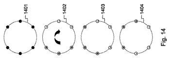
図1A及び図1Bは、パターンになった電極ガイドと、電気コネクタと、集積電気回路とを有するメッシュ又はプレートの実施態様を示す。メッシュ又はプレートにより、複数の電極を固定クラスタ、例えば、三角形、正方形、行、又は六角形のクラスタに配置することができる。或いは、電極は、平行する穿孔を有するブロックを通して挿入することができる。そのようなブロックは体外実験に有用であるが、ブロックは重く邪魔であるため、患者の治療での有用性は低い。ブロックは(及びプレートも)、腫瘍の形状に適合させて電極を柔軟に位置決めすることができず、又は血管等の繊細な構造を避けるために柔軟に位置決めすることができない。電極の手動での位置決めは非常に柔軟性があるが、非常に規則的な等距離パターンでの平行挿入を保証しない。さらに、各電極に1つの電気ケーブルがあるため、多くのケーブルは容易に混乱する。異なる電極の端部にある複数のケーブルは、これらの電極を曲げる傾向も有する。ケーブルを1つずつ、発電機の剛性コネクタ(又は電極と発電機との間のスイッチボックス)に正しく接続するには、大きな注意を払う必要がある。これは、操作者又は医師が入念に行わなければならない時間のかかる作業である。1つの誤りが治療の結果を台無しにするおそれがある。 1A and 1B show an embodiment of a mesh or plate having patterned electrode guides, electrical connectors, and integrated electrical circuits. A plurality of electrodes can be arranged in a fixed cluster, for example, a triangular, square, row, or hexagonal cluster by means of a mesh or plate. Alternatively, the electrode can be inserted through a block having parallel perforations. While such blocks are useful for in vitro experiments, they are not useful in treating patients because the blocks are heavy and disturbing. The block (and also the plate) cannot be flexibly positioned to fit the shape of the tumor, or to avoid delicate structures such as blood vessels. Manual positioning of the electrodes is very flexible but does not guarantee parallel insertion in a very regular equidistant pattern. Furthermore, because there is one electrical cable for each electrode, many cables are easily confused. Cables at the ends of different electrodes also have a tendency to bend these electrodes. Great care must be taken to properly connect the cables one by one to the rigid connector of the generator (or the switch box between the electrode and the generator). This is a time consuming task that must be done carefully by the operator or physician. One mistake can ruin the outcome of the treatment.
本発明の好ましい実施形態では、この問題は、プラスチックのように復元力がなく、綿のように弾性を有さないが高い可撓性を有する布と整合する、例えば、ナイロンで作られた合成メッシュを使用することにより解決される。或いは、メッシュは、シリコーン様の透明又は不透明の可撓性メッシュであることができる。 In a preferred embodiment of the present invention, the problem is that the composite is made of, for example, nylon, which is not resilient like plastic and matches a highly flexible fabric that is not elastic like cotton. This is solved by using a mesh. Alternatively, the mesh can be a silicone-like transparent or opaque flexible mesh.
メッシュ又はプレートにおいて、電極を挿入するためのグリッドになった穴が予見される。有利なことには、例えば、異なる電極間隔、例えば、1.5cm、2cm、3cm、4cm、5cmを有する3〜5個の穴×3〜5個の穴を有する矩形グリッド、異なる電極間隔を有する球形グリッド、及び他の可能な構成のようないくつかのパターンがある。図1Aは、矩形グリッドになった穴101を有するメッシュ100を示し、その一方で、図1Bは、球形グリッドになった穴111を有するメッシュ110を示す。
In the mesh or plate, a grid of holes for inserting the electrodes is foreseen. Advantageously, for example, different electrode spacing, e.g. 3-5 holes with 1.5 cm, 2 cm, 3 cm, 4 cm, 5 cm x rectangular grid with 3-5 holes, with different electrode spacing There are several patterns such as a spherical grid, and other possible configurations. FIG. 1A shows a
可撓性により、超音波を通して位置を制御し、監視することができるように、電極の挿入後にメッシュ又はプレートを曲げることができる。可撓性により、メッシュ又はプレートにしわを寄せて、腫瘍の形状に適合させ、又は繊細な構造、例えば、血管を避けることもできる。 Flexibility allows the mesh or plate to bend after electrode insertion so that position can be controlled and monitored through ultrasound. Flexibility can also wrinkle the mesh or plate to conform to the shape of the tumor or avoid delicate structures such as blood vessels.
メッシュ又はプレートの各開口部に、プラグが取り付けられ、又はメッシュ若しくはプレートに集積される。プラグは、図2A及び図2Bに示されるように、開口部の周囲に配置することができ、又はプラグは、図2C及び図2Dに示されるように、対応する穴のすぐ隣に配置してもよい。 At each mesh or plate opening, a plug is attached or integrated into the mesh or plate. The plug can be placed around the opening, as shown in FIGS. 2A and 2B, or the plug can be placed directly next to the corresponding hole, as shown in FIGS. 2C and 2D. Also good.
開口部の周囲にプラグ202+203又は212+213を有する実施態様は、消費スペースが小さく、ワイヤ216が周囲で動く程度が低いため、より洗練されている。プラグが、プラスチック部分203又は213と、導電性の金属部分202又は212とからなることに留意する。プラグ215及びワイヤ216は、パッケージを開く際に、電極201又は211の上部に巻くことができる。次に、プラグ215を下に滑らせて、メッシュ又はプレート209又は219に集積されたプラグの導電部分202又は212に接続する。図2A及び図2Bは、メッシュ又はプレートに集積された配線204又は214をさらに示す。配線は、メッシュに集積されるか、又は中間滅菌プレート若しくはスイッチボックスのフロントパネルに配置されて、間違いなく電極を接続するに当たって医師を支援するLEDインジケータを制御するために使用することもできる。
開口部227又は237の近傍にプラグ222+223又は232+233を有する実施態様は、ワイヤ236が周囲でより容易に移動可能であり、開口部及びプラグが占めるスペースがより大きいため、洗練さがいくらか落ちる。占めるスペースがより大きいことは特に、電極が互いに近い場合に問題であり得る。ここでも、プラグが、プラスチック部分223又は233と、導電性の金属部分222又は232とからなることに留意する。電極221又は231の上部から延びるワイヤ236はプラグ235で終端し、プラグ235は、メッシュ又はプレートに集積されたプラグの導電部分222又は232に接続する。対応する穴の近傍にプラグを有するバージョンは、電気絶縁に関してより安全であり、メッシュ又はプレートの高さを考慮しての深度の厳密な測定は、問題ではない。図2C及び図2Dは、メッシュ又はプレート229又は239に集積された配線224又は234をさらに示す。
図3に示されるように、電気ワイヤ302及び303は、穴及び対応するプラグ301毎にメッシュに織り込まれ、又はプレート300に集積される。これらの個々に絶縁されたワイヤを組み合わせて、単一の電気ケーブルコネクタ304にし、電気ケーブルコネクタ304は、メッシュ又はプレート300を出て、スイッチボックスに接続される。
As shown in FIG. 3, the
可撓性メッシュ又はプレートへの代替として、電極405は、図4Aに示されるように、例えば、1cm毎に穴を有する多穿孔プレート404を通して運ぶことができる。プレート404は、中実であってもよく、穴を開けてもよく、又は中空であってもよく、小管がプレートの上面と下面とをつなぐ。或いは、プレート及び小管が、平行挿入を保証するのに十分な剛性を有する場合、上部又は下部表面プレートを省くことができる。すべての穴は、電気プラグと、電気配線とを有するが、すべての穴をRFA処置に使用する必要はない。このプレート404は、特定の厚さ、例えば、3cm〜4cmを有し、電極の平行挿入を保証する。プレートは、治療が必要な患者402の臓器、例えば、肝臓に直接置くことができる。より好ましくは、プレート404は、手術台401に固定して取り付けられたロボットアーム403により保持される。そのようなロボットアーム403は、プレート404を所望の位置及び向き、通常は治療する臓器の5cm上に固定して保持できるようにし、それにより、すべての電極405を平行に挿入することができ、超音波プローブが電極405の挿入深度及び位置を制御するのに十分なスペースを残す。ロボットアーム403は、手動で所望の位置に移動する。或いは、ロボットアーム403は位置測定手段を備える。
As an alternative to a flexible mesh or plate, the
図4Bは、完全に自動化されたロボットアーム412を有する変形実施形態を示し、ロボットアーム412の端部は、電極413が事前装荷されたプレート411からなる。ロボットアーム412は、治療すべき臓器、例えば、肝臓にナビゲーションにより位置決めされる。このロボットアーム412は、位置測定システムと、アーム412及び電極413を自動的に移動させるモータとを備える。電極413は、ロボットアーム412自体の部分をなす電動機構により送り出される。挿入深度は、腫瘍及び担腫瘍臓器の術前及び術中の撮像に基づく。電極は、上述した様式と同様に配線される。
FIG. 4B shows an alternative embodiment having a fully automated
電極の活性部分の長さは、好ましくは、電極の位置での腫瘍組織500の厚さに、両側に1cmの安全マージンを加えたものに対応する。これは、RFAプロセスにおいて患者511の肝臓腫瘍500の治療に使用されるいくつかの電極501、502、503、504、505、506、507、508、509、510に関して図5に示される。電極の活性先端長601は、絶縁プラスチックシート602を電極上で、このシートが腫瘍の前縁に到達する1cm以内になるまで滑らせることで適合可能である。これは、白色のまま残された電極の上部分で図5に示される。シート602のスライドの前に、電極600を好ましい深度まで、すなわち、腫瘍の下縁の1cm下に挿入しなければならない。電極600の好ましい深度までの挿入及びシートの好ましい深度までのスライドは、超音波又は電極を視覚化する変形技術を使用して行い得る。図6は、絶縁シート602の適切な深度へのスライドを支援し得る電極上のハンドル603と、配線604と、印605とをさらに示す。
The length of the active part of the electrode preferably corresponds to the thickness of the
或いは、限られた数の電極を有する単純な場合、これらの電極の長さは異なり得、医師は、各位置に、電極挿入前に正しい活性長を有する電極を選ぶことができる。 Alternatively, in the simple case of having a limited number of electrodes, the lengths of these electrodes may be different, and the physician can select an electrode with the correct active length at each location prior to electrode insertion.
活性部分の長さは、同じ腫瘍に挿入される電極間で、局所的な厚さに従って異なり得る。その結果、好ましくは、各サイズ及び形状に適合可能な、腫瘍全体容積500の最適なカバーリングが達成可能である。
The length of the active part can vary according to the local thickness between electrodes inserted into the same tumor. As a result, an optimal covering of the
事前配線したメッシュ又はプレートを通して電極の挿入する場合、受動的なロボットアームを使用して、電極が完全に互いに平行になることを保証することができる。調整可能なガイド装置により、超音波ガイダンスとの解消を最小にした状態で、患者のペース制約にも拘わらず、電極を挿入することができる。 When inserting electrodes through a pre-wired mesh or plate, a passive robot arm can be used to ensure that the electrodes are completely parallel to each other. With an adjustable guide device, electrodes can be inserted with minimal guidance from ultrasound guidance, regardless of patient pace constraints.
接地プレートが、患者の体の部分の、電極から特定の距離の箇所に、通常、大腿部に配置される。接地プレートは、焼灼プロセス前又は焼灼プロセス中に、又はこれら両方で定期的な時間間隔で個々の各電極と接地プレートとの間の電気インピーダンスを測定するために使用される。そのようなインピーダンス測定は、三重の種類の情報を与える。
−組織の治療前の特性インピーダンスがすべての電極位置で等しく、各電極から接地プレートへの距離がおおよそ等しいと仮定される場合、測定されるインピーダンスの差は、露出電極先端の長さの差によるものである。インピーダンスは、露出先端の長さの増大に伴って線形に低減する。したがって、PCは各電極の長さを容易に計算することができる。
−治療前インピーダンスの測定により、グリッド内のどの位置が電極に占められており、どの位置が占められていないかをチェックすることができる。後者の場合、インピーダンスは無限に高くなる。
−焼灼プロセス中にインピーダンスを断続的に測定することにより、RFプロセスのさらなる2D又は3D監視が可能であり、十分に高いインピーダンスが、すべての標的組織が失活したことを示す場合、焼灼を止めることができる。
A ground plate is typically placed on the thigh at a specific distance from the electrodes on the patient's body part. The ground plate is used to measure the electrical impedance between each individual electrode and the ground plate at regular time intervals before or during the cauterization process, or both. Such an impedance measurement gives triple types of information.
If the pre-treatment characteristic impedance of the tissue is equal at all electrode positions and the distance from each electrode to the ground plate is approximately equal, the measured impedance difference is due to the difference in the length of the exposed electrode tip Is. The impedance decreases linearly with increasing exposed tip length. Therefore, the PC can easily calculate the length of each electrode.
-Measurement of the pre-treatment impedance can check which position in the grid is occupied by the electrode and which position is not occupied. In the latter case, the impedance is infinitely high.
-By intermittently measuring impedance during the ablation process, further 2D or 3D monitoring of the RF process is possible, stopping the ablation if a sufficiently high impedance indicates that all target tissues have been deactivated be able to.
本発明による装置の部分をなすスイッチボックスは、単独であってもよく、又は発電機に統合してもよい。スイッチボックスは、メッシュ又はプレートから結合電気配線を受け取る。スイッチボックスは、複数の電極の空間的制御を可能にする。スイッチボックスは、異なる電極を渡る電流及び異なる電極間の電流を再分配できるハードウェアを含む。スイッチボックスは、回路に組み込んで、特定の瞬間に特定の電極対間を実際に流れる電流を瞬間的に変更することができる可変電気抵抗も含む。 The switch box forming part of the device according to the invention may be alone or integrated into the generator. The switch box receives coupled electrical wiring from the mesh or plate. The switch box allows spatial control of multiple electrodes. The switch box includes hardware that can redistribute current across different electrodes and between different electrodes. The switch box also includes a variable electrical resistance that can be incorporated into the circuit to instantaneously change the current that actually flows between a particular electrode pair at a particular moment.
すでに上で示したように、本発明によるRFA装置は、好ましくは、
−動作アルゴリズム、
−処置のログ、
−電極の位置、電極のインピーダンス、活性長、及び活性化状態(正又は負)の視覚化、
−データ、メニューの導入
を有するPCを含む。
As already indicated above, the RFA device according to the invention is preferably
-Operation algorithm,
-Log of actions,
-Visualization of electrode position, electrode impedance, active length, and activation state (positive or negative);
-Includes PC with data, menu introduction.
PCは、スイッチボックスを制御又は命令することにより、焼灼プロセスを操縦できるようにする。RFA装置の可能な実施態様では、基本電流は発電機のフロントパネルで設定される。RFA装置の代替版では、PCは発電機の基本電流も制御する。まず、PCは、個々の各電極と接地プレートとの間で流れる小電気電流を有する治療前サイクルを命令する。これにより、PCは各電極の長さについての情報を得ることができる。PCに、グリッド内のどの位置が電極で占められており、どの位置が占められていないかをチェックさせることもできる。PCはさらに、以下の段落において説明する動作アルゴリズムを実行する。 The PC allows the ablation process to be steered by controlling or commanding the switch box. In a possible implementation of the RFA device, the basic current is set on the front panel of the generator. In an alternative version of the RFA device, the PC also controls the basic current of the generator. First, the PC commands a pre-treatment cycle with a small electrical current that flows between each individual electrode and the ground plate. Thereby, the PC can obtain information about the length of each electrode. It is also possible to have the PC check which position in the grid is occupied by the electrode and which position is not occupied. The PC further executes the operational algorithm described in the following paragraphs.
PCは動作アルゴリズムをさらに実行する。これらの治療アルゴリズムは、無線周波数電極が最適に実行されて、腫瘍が大きい場合であっても、又は腫瘍の形状が不規則な場合であっても、腫瘍と、腫瘍を囲む安全マージンとを含む確実で個々の状況に合った焼灼ゾーンを取得するように設計される。治療アルゴリズムのパラメータは、事前に設定することもでき、又は手動で適合させることもできる。 The PC further executes an operation algorithm. These treatment algorithms include a tumor and a safety margin that surrounds the tumor, even if the radio frequency electrodes are optimally performed and the tumor is large or the shape of the tumor is irregular Designed to obtain abundant and specific ablation zones. The parameters of the treatment algorithm can be preset or adapted manually.
動作アルゴリズムは、以下の事前無線周波数入力パラメータに基づく:
−電極の非絶縁部分の長さ、
−電極の数、
−スペース内の電極の分布、すなわち、パターン及び電極間隔、
−組織の種類、並びに
−組織の灌流の有無。
The operating algorithm is based on the following pre-radio frequency input parameters:
The length of the non-insulated part of the electrode,
-Number of electrodes,
The distribution of the electrodes in the space, i.e. the pattern and the spacing between the electrodes,
-Tissue type, and-Whether tissue is perfused.
動作アルゴリズムは、無線周波数焼灼中に測定される以下の入力パラメータにさらに基づき得る:
−電極と接地プレートとの間のインピーダンス、又は
−電極と基準電極との間のインピーダンス、又は
−電極対間のインピーダンス。
The operational algorithm may be further based on the following input parameters measured during radio frequency ablation:
The impedance between the electrode and the ground plate, or the impedance between the electrode and the reference electrode, or the impedance between the electrode pair.
動作アルゴリズムは、以下の出力パラメータを決定する:
−群として活性化する電極、
−各電極群が活性化される電気モード、すなわち、単極又は双極、
−双極モードで、どの電極が正電極として活性化され、どの電極が負電極として活性化されるか、
−電極の活性化モード、すなわち、順次モード、同時モード、又は切り替えモード、
−切り替えモードの場合、各電極群の活性化の時間間隔及び群が循環移動で活性化される順序、
−電力出力及び電流強度、並びに
−焼灼処置全体の持続時間。
The operational algorithm determines the following output parameters:
-Electrodes activated as a group,
The electrical mode in which each electrode group is activated, i.e. monopolar or bipolar,
-In bipolar mode, which electrode is activated as a positive electrode and which electrode is activated as a negative electrode,
The activation mode of the electrodes, i.e. sequential mode, simultaneous mode or switching mode,
-In the switching mode, the activation time interval of each electrode group and the order in which the groups are activated by cyclic movement;
Power output and current intensity, and duration of the entire cauterization procedure.
体外ウシ肝臓内に複数の電極を使用する実験研究に基づいて、アルゴリズム例を開発した。そこでは、電極2つの2行間に双極電流を有す得る正方形パターンに配置され、各行が電気的に並列接続される4つの平行する単純な3cm電極の使用が、非常に確実で再現性があり、電極間のエリアの完全な凝固、電極間エリア外の3〜5mmの凝固を示した。そこで、電極間隔は2cm以下が選択され、電力は60W以下が選択され、電力は、事前定義された固定の持続時間を有するアルゴリズムを使用するのではなく、むしろ、自動電力遮断を用いてインピーダンス上昇まで与えられた。結果として凝固の持続時間は6分〜8分であった。 An example algorithm was developed based on experimental studies using multiple electrodes in an extracorporeal bovine liver. There, the use of four parallel simple 3 cm electrodes, arranged in a square pattern that can have a bipolar current between two rows of two electrodes, with each row electrically connected in parallel, is very reliable and reproducible. Showed complete solidification of the area between the electrodes, 3-5 mm of solidification outside the area between the electrodes. Therefore, the electrode spacing is selected to be 2 cm or less, the power is selected to be 60 W or less, and the power is not using an algorithm with a predefined fixed duration, but rather is increased in impedance using automatic power cut-off. Until given. As a result, the duration of coagulation was 6-8 minutes.
実験は、2つの電極群間での双極モードが、ファラデー効果により同じ4電極の連続単極活性化、又は同じ4電極の連続した双極活性化よりも効率的で確実であることを示した。 Experiments have shown that the bipolar mode between the two electrode groups is more efficient and reliable than the same four-electrode continuous monopolar activation or the same four-electrode continuous bipolar activation due to the Faraday effect.
さらに、非絶縁長Lcmを有する4つの同様の電極間のエリアの凝固に必要な理想的な電力が、60ワット×L/3に等しいことが実験的に学習された。 Furthermore, it was experimentally learned that the ideal power required to solidify the area between four similar electrodes having a non-insulating length Lcm is equal to 60 watts × L / 3.
実験は、切り替えモードが、第1の立方体そしてよりも第2の立方体が活性化されて、電極3つの2行で決まる組織の2つの隣接する立方体を連続して凝固し、各行の第2の電極は第1及び第2の立方体に属するする連続モードよりも効率的であることをさらに示した。実際に、連続モードでは、両立方体に共通する電極の近傍にある組織は、第1の立方体の凝固後、完全に脱水状態になる。これは、第2の立方体での正しい電流の流れを妨げる。より効率的であることの他に、切り替えモードは連続モードよりも高速で作業もする。 The experiment shows that the switching mode activates the first cube and more than the second cube to solidify two adjacent cubes of tissue determined by the two rows of electrodes in succession, the second of each row It was further shown that the electrode is more efficient than the continuous mode belonging to the first and second cubes. In fact, in continuous mode, the tissue in the vicinity of the electrode common to the compatible cuboid is completely dehydrated after the first cube solidifies. This hinders correct current flow in the second cube. Besides being more efficient, the switching mode also works faster than the continuous mode.
同様に、実験は、切り替えモードが同時モードよりも効率的であることを示した。そのような同時モードでは、電流はより大きな容積にわたって薄まり、大きな腫瘍の場合に問題を生じさせ得る。さらに、同時モードでは、電流は、ファラデー効果により、電極が占める容積の境界に向かって押しやられる。その結果、所望の治療容積を囲む必要な凝固の辺縁が拡大する。結果として生じる凝固は、換言すれば、同時モードよりも確実性及び予測可能性が低い。 Similarly, experiments have shown that the switching mode is more efficient than the simultaneous mode. In such a simultaneous mode, the current diminishes over a larger volume, which can cause problems in the case of large tumors. Furthermore, in the simultaneous mode, the current is pushed towards the boundary of the volume occupied by the electrode due to the Faraday effect. As a result, the necessary coagulation edge surrounding the desired treatment volume is enlarged. The resulting coagulation, in other words, is less reliable and predictable than the simultaneous mode.
本発明の好ましい実施態様では、電極は、互いに平行して、電極間隔2cmを有する矩形パターンで腫瘍内に挿入される。腫瘍全体及び安全マージン1cmがカバーされる。矩形パターンの電極がカバーエリア外になってしまう場合、メッシュ又はプレートの可撓性を利用して、エリア内の外部近くに電極を配置する。電極の長さは、腫瘍の局所的な厚さと、腫瘍の前側又は上部の境界よりも1cm上と、腫瘍の下側又は下部の1cm下とに適合される。腫瘍に対する相対位置に応じて、3つのタイプの電極を区別することができる:2方向において健康な組織に接する角電極、1方向において健康な組織に接する側部電極、及び健康な組織に接触しない中央電極。組織は、中央電極間のインピーダンスが2〜3倍に増大した場合、十分に凝固する。角電極は、2方向において健康な組織に接した状態を保つため、低インピーダンスに維持される。側部電極では、中間のインピーダンス上昇が見られる。一様な凝固の場合、インピーダンスは、急激なインピーダンスの増大が見られる完全凝固点までは、治療全体を通してほぼ一定に保たれる。一般原理として、電極ブロックは、すべての電極が等しい時間量だけ活性化されたような特定の様式後に活性化される。この一般原理を守るいくつかの方式について、図7、図8、図9、図10、図11、及び図12のそれぞれを参照して以下の段落において説明する。 In a preferred embodiment of the invention, the electrodes are inserted into the tumor in a rectangular pattern with an electrode spacing of 2 cm parallel to each other. The entire tumor and a safety margin of 1 cm are covered. If the rectangular pattern electrode is outside the cover area, the electrode is placed near the outside in the area using the flexibility of the mesh or plate. The length of the electrode is adapted to the local thickness of the tumor, 1 cm above the front or upper boundary of the tumor and 1 cm below or below the tumor. Depending on the relative position to the tumor, three types of electrodes can be distinguished: a corner electrode that contacts healthy tissue in two directions, a side electrode that contacts healthy tissue in two directions, and no contact with healthy tissue Central electrode. The tissue is fully coagulated when the impedance between the central electrodes is increased 2-3 times. The square electrode is kept in a low impedance in order to maintain a state in contact with healthy tissue in two directions. In the side electrodes, an intermediate impedance rise is seen. In the case of uniform clotting, the impedance remains approximately constant throughout the treatment until the complete clotting point where a rapid increase in impedance is seen. As a general principle, the electrode block is activated after a certain manner in which all electrodes are activated for an equal amount of time. Several schemes that adhere to this general principle are described in the following paragraphs with reference to FIGS. 7, 8, 9, 10, 11, and 12, respectively.
3×3電極及び2×2の電極群である場合、図7は、4つの通常活性化パターンN1、N2、N3、及びN4が1回使用され、中央電極と比較して低い側部電極の活性化を補償する活性化パターンZが2回使用され、中央電極と比較して低い角電極の活性化を補償する活性化パターンH1が3回使用される方式を示す。完全なサイクルは、9つの順次活性化からなる:H1−Z−H1−N2−Z−H1−N3−N4 In the case of a 3 × 3 electrode and 2 × 2 electrode group, FIG. 7 shows that four normal activation patterns N1, N2, N3, and N4 are used once and the lower side electrode is lower than the central electrode. An activation pattern Z that compensates for activation is used twice, and an activation pattern H1 that compensates for activation of a lower corner electrode compared to the central electrode is used three times. A complete cycle consists of 9 sequential activations: H1-Z-H1-N2-Z-H1-N3-N4
4×3電極の場合、2×2電極群を用いる解決策はない。図8は、3×2電極群を有する解決策を示し、3つの通常活性化パターンD1、D2、及びD3が1回使用され、角電極の低い活性化を補償する活性化パターンH2が1回使用される。完全なサイクルは4つの順次活性化からなる:D1−D2−D3−H2 In the case of 4 × 3 electrodes, there is no solution using 2 × 2 electrode groups. FIG. 8 shows a solution with a 3 × 2 electrode group, where three normal activation patterns D1, D2 and D3 are used once and an activation pattern H2 is compensated once to compensate for the low activation of the corner electrodes. used. A complete cycle consists of four sequential activations: D1-D2-D3-H2
図9は、3×3電極であり、電極群が3×2である同様の活性化方式を示す。2つの通常活性化パターンD4及びD5の後に、角電極の低い活性化を補償する活性化パターンH3が続く。この場合、完全なサイクルは4つの順次活性化からなる:D4−D5−H3。3×2電極群は、2×2電極群と比較して有利であり、その理由は、インピーダンスがより低く、電流強度がより高く、凝固がより高速であるためである。3×2電極の場合、より強力な発電機が必要とされ得る。 FIG. 9 shows a similar activation scheme with 3 × 3 electrodes and 3 × 2 electrode groups. Two normal activation patterns D4 and D5 are followed by an activation pattern H3 that compensates for the low activation of the corner electrodes. In this case, the complete cycle consists of four sequential activations: D4-D5-H3, the 3 × 2 electrode group is advantageous compared to the 2 × 2 electrode group because the impedance is lower, This is because the current intensity is higher and the solidification is faster. In the case of 3 × 2 electrodes, a more powerful generator may be required.
正電極3個の行及び負電極3個の行が使用される場合、行と電極との間の中央部分は、ファラデー効果により凝固の程度が低い。交互になった行の場合、すなわち、正−負−正電極を有する1行及び負−正−負電極を有する1行の場合、電極間の中央部分は、求心電流の結果として凝固が過剰になる。この問題への解決策は、図10に示されるように、行が、極性の等しい電極を有する遠心分離方式と、図11に示されるように、行が、極性が交互になった電極を有する向心方式とのを交互にすることにある。この原理は、3×3電極の状況及び3×4電極の状況の両方に適用される。 When three rows of positive electrodes and three rows of negative electrodes are used, the central portion between the rows and the electrodes is less solidified due to the Faraday effect. In the case of alternating rows, ie one row with positive-negative-positive electrodes and one row with negative-positive-negative electrodes, the central part between the electrodes is excessively coagulated as a result of centripetal current. Become. A solution to this problem is that the rows have electrodes of opposite polarity as shown in FIG. 10 and the rows have electrodes of alternating polarity as shown in FIG. It is to alternate with the centripetal method. This principle applies to both 3 × 3 electrode situations and 3 × 4 electrode situations.
4×4電極の場合、図12は、4×2電極群を有する活性化方式を示す。3つの通常活性化パターンV1、V2、及びV3の後に、角電極の活性化が低いことを補償する活性化パターンH4が続く。完全なサイクルは4つの順次活性化からなる:V1−V2−V3−H4。図11に示される向心サイクルの後、遠心分離サイクルが続けられる。 In the case of 4 × 4 electrodes, FIG. 12 shows an activation scheme with 4 × 2 electrode groups. The three normal activation patterns V1, V2, and V3 are followed by an activation pattern H4 that compensates for the low activation of the corner electrodes. A complete cycle consists of four sequential activations: V1-V2-V3-H4. After the centripetal cycle shown in FIG. 11, the centrifugation cycle is continued.
まとめると、x×y電極を行内で活性化して、一様の凝固を得ることができる。この場合、行は、いずれか大きい方のx個又はy個の電極を含む。このようにして、凝固速度は増大し、別個に活性化する必要がある角電極間の大きな距離が回避される。しかし、電極の行の活性化を可能にするために、より強力な発電機が必要である。力のあまり強くない発電機の場合、各行がいずれか小さい方のx又はy電極を含むその他の方向を考慮することができる。最初の半サイクルでは、2つの隣接する行の群が次々と活性化される行パターンが辿られる。向心極性方式が使用される。すなわち、各行は正又は負のいずれかの電極を含む。角電極の低い活性化を補償するために、電極の最初と最後の行で構成される群の追加の活性化が実行される。第2の半サイクルでは、遠心分離に相当するものを受ける。 In summary, the xy electrode can be activated in a row to obtain a uniform solidification. In this case, the row includes the larger x or y electrodes. In this way, the coagulation rate is increased and large distances between the corner electrodes that need to be activated separately are avoided. However, a more powerful generator is needed to enable activation of the electrode rows. For less powerful generators, other directions can be considered, with each row including the smaller x or y electrode. In the first half cycle, a row pattern is followed in which two adjacent groups of rows are activated one after the other. A centripetal polarity scheme is used. That is, each row contains either positive or negative electrodes. In order to compensate for the low activation of the corner electrodes, an additional activation of the group consisting of the first and last rows of electrodes is performed. In the second half cycle, the equivalent of centrifugation is received.
インピーダンスが25Ωを超えるとすぐに、発電機はオフに切り替えられる。より長い電極が使用され、且つ/又は電極間隔が狭く、且つ/又はより多数の電極が同時に活性化される場合、インピーダンスは低減し、より強力な発電機が必要である。発電機は、スイッチ周波数が1/200ミリ秒よりも高くなった場合にもすぐにオフに切り替えられる。理想的なスイッチ間隔は200ミリ秒〜500ミリ秒である。燃焼効果なしでその他の電極で囲まれるエリア内の一様な凝固を得るためには、理想的なエネルギー密度は4.2〜5ワット/cm3である。 As soon as the impedance exceeds 25Ω, the generator is switched off. If longer electrodes are used and / or the electrode spacing is narrow and / or more electrodes are activated at the same time, the impedance is reduced and a more powerful generator is needed. The generator is also switched off immediately if the switch frequency is higher than 1/200 ms. The ideal switch interval is 200 milliseconds to 500 milliseconds. The ideal energy density is 4.2-5 watts / cm 3 to obtain uniform solidification within the area surrounded by the other electrodes without burning effects.
図13は、球形又は円筒形を凝固すべき場合の電極の一意決めを示す。正方形又は矩形と比較して、角電極1301、1302、1303、及び1304は内側に移動する。次に、電極は、それでもなお正方形又は矩形の部分をなしているかのように活性化される。この方式は、半径Rを有する球形の場合に機能し、中央電極は活性先端長2Rを有し、外周電極は長さ2/3Rを有する。電極間隔はRに等しい。この方式は、半径R及び高さhを有する円筒形の場合も有用である。この場合、電極間隔はRに等しく、すべての電極の活性先端長はhに等しい。隣接する電極が異なる活性先端長を有する場合、最短活性先端長は、最長活性先端長の2/3に少なくとも等しくなければならない。そうでなければ、凝固が不完全になるおそれがある。
FIG. 13 shows the uniqueness of the electrodes when the sphere or cylinder is to be solidified. Compared to a square or rectangle, the
図14に示されるように、円筒形容積は、9つの電極の代わりに6つの電極を有する方式1401、すなわち、中央電極がない方式を使用して凝固することもできる。3つの電極は正の極性を有し、3つの電極は負の極性を有する。正の極性を有する電極セットは、続く方式1402、1403、及び1404により図14に示されるように、循環して交代する。電極間隔は、長くとも電極の活性先端長hの2/3であることができる。
As shown in FIG. 14, the cylindrical volume can also be solidified using a
図15は、本発明の部分をなすスイッチボックスの好ましい実施形態での異なる要素の全体像を与える。各スイッチは、組織に挿入された電極に接続される。すべてのスイッチは、発電機の高出力及び低出力との接続を共有する。図15の共通コントローラは疑似負荷をかける。コントローラは、共通して印加された発電機電圧を測定し、インピーダンス測定中に基準電極に接続する。ホストプロセッサは、光学的に分離された通信バスを介して分散したすべてのコントローラを制御する。これは、マトリクスの実際の概念が存在する唯一のロケーションである。疑似負荷は、この制御ロケーションからも制御される。エネルギーを組織に与えるために、ホストプロセッサは、例えば、隣接する電極が発電機の逆の極性に接続され、組織に電流を流すようにスイッチを制御する。組織のインピーダンスを測定するために、電流は、好ましくは、1つの電極と基準電極又はプレートとの間で測定される。共通の基準電極に関して測定される場合、測定は近傍電極のインピーダンスから独立する。エネルギーを組織に与えている間、基準電極を切断して、この電極への電流漏れを回避する。インピーダンス測定を実行するには、治療と同じ電流を使用することができるが、組織焼灼に必要な時間の何分の一かしか与えられない。印加される電力を時間で乗算したものに対応するエネルギー量は、測定時間が短いことにより、それに比例して低い。基準電極の一般性質により、電流測定は、共通のコントローラでも同様に実行することができる。これは、電極から電流測定回路をなくすことにより、他のすべての電極を単純化することができる。しかし、組織へのエネルギー印加中に、正しい動作を確認する手段又は深刻な過電流の場合に電極を遮断する手段として、局所的な測定を使用することもできる。基準電極に接続する同じ共通コントローラは、あらゆるノードのインピーダンスの計算に必要な電圧測定も実行する。共通コントローラは、他のスイッチが活性化されていない場合、発電機の出力に疑似負荷を接続もする。 FIG. 15 gives an overview of the different elements in the preferred embodiment of the switch box forming part of the present invention. Each switch is connected to an electrode inserted into the tissue. All switches share a connection with the high and low output of the generator. The common controller in FIG. 15 applies a pseudo load. The controller measures the commonly applied generator voltage and connects to the reference electrode during impedance measurement. The host processor controls all the distributed controllers via an optically isolated communication bus. This is the only location where the actual concept of the matrix exists. The pseudo load is also controlled from this control location. To provide energy to the tissue, the host processor, for example, controls the switch so that adjacent electrodes are connected to the opposite polarity of the generator and current flows through the tissue. In order to measure the impedance of the tissue, the current is preferably measured between one electrode and a reference electrode or plate. When measured with respect to a common reference electrode, the measurement is independent of the impedance of neighboring electrodes. While applying energy to the tissue, the reference electrode is cut to avoid current leakage to this electrode. To perform impedance measurements, the same current as the treatment can be used, but only gives a fraction of the time required for tissue ablation. The amount of energy corresponding to the applied power multiplied by time is proportionally lower due to the shorter measurement time. Due to the general nature of the reference electrode, the current measurement can be performed with a common controller as well. This can simplify all other electrodes by eliminating the current measurement circuit from the electrodes. However, local measurements can also be used as a means of confirming correct operation during energy application to the tissue or as a means of interrupting the electrode in case of severe overcurrent. The same common controller connected to the reference electrode also performs the voltage measurements necessary to calculate the impedance of every node. The common controller also connects a pseudo load to the output of the generator when no other switch is activated.
図16は、光アイソレータを介して共通通信バスに接続された単一のスイッチを示す。すべてのスイッチは、同一のハードウェア及びソフトウェアからなり、唯一の差は、各自に向けられたメッセージを識別できるようにするアドレス値である。 FIG. 16 shows a single switch connected to a common communication bus via an optical isolator. All switches consist of the same hardware and software, the only difference being the address value that allows to identify the message directed to each.
スイッチボックスは、電気機械中継器を使用して構築することができる。寿命が限られたかさばる機械中継器の代わりに、MOSFETを考慮することができる。しかし、MOSFETは、発電機の比較的高い出力周波数では完全なアイソレータではない。ドレインとソースとの間に約40pFの寄生コンデンサを有する低漏出MOSFETであっても、発電機の高出力と低出力との間に相当量の電力を生じさせる。MOSFETを使用するACスイッチを構築することで、これらの装置のうちの2つが直列に配置され、全体インピーダンスが16kΩに効率的に増大する。これらの値は、約0.1Ωであるオン状態抵抗と比較して高い。しかし、5×5マトリクスのように大量のこれらの装置を並列接続すると、結合インピーダンスは640Ωに低下する。これは、発電機の出力電力の大部分がMOSFET内で消散し、焼灼プロセスに寄与せず、より強力な発電機が必要なことを意味する。電力MOSFETの現在の状態では、多くの出力電力を無駄にせずには、そのような大きなスイッチマトリクスを実施することは現実的ではない。小型で耐久性が高い中継器を使用して、漏出が低いMOSFETが利用できるようになるまで、漏出を解消することができる。 The switch box can be constructed using electromechanical repeaters. Instead of mechanical repeaters with limited lifetime, MOSFETs can be considered. However, MOSFETs are not perfect isolators at the generator's relatively high output frequency. Even a low leakage MOSFET with a parasitic capacitor of about 40 pF between the drain and source will generate a significant amount of power between the high and low output of the generator. By constructing an AC switch using MOSFETs, two of these devices are placed in series, effectively increasing the overall impedance to 16 kΩ. These values are high compared to the on-state resistance which is about 0.1Ω. However, when a large amount of these devices are connected in parallel like a 5 × 5 matrix, the coupling impedance is reduced to 640Ω. This means that most of the output power of the generator is dissipated in the MOSFET and does not contribute to the cauterization process and a more powerful generator is required. In the current state of power MOSFETs, it is not practical to implement such a large switch matrix without wasting a lot of output power. Leakage can be eliminated using a small and highly durable repeater until a low leakage MOSFET is available.
マトリクス構造は仮想である:分散したすべてのプロセッサは共通のシリアル通信バスを共有する。各プロセッサは、このバス上の別個のアドレスで一意に識別される。マトリクスの概念は、ルックアップテーブルを介してアドレスを2次元マトリクスにマッピングするホストプロセッサにのみ存在する。 The matrix structure is virtual: all distributed processors share a common serial communication bus. Each processor is uniquely identified by a separate address on this bus. The concept of a matrix exists only in host processors that map addresses to a two-dimensional matrix via a lookup table.
ローカルマイクロコントローラを使用して、スイッチを制御する。ローカルマイクロコントローラは、共通シリアルデータバス線並びに共通リセット・エラー線を共有する。通信は半二重式で行われる。各スレーブノードは、マスタ又はホストにより駆動されるデータ線を常時監視する。コマンドがスイッチコントローラにアドレス指定されると、スイッチコントローラは、そのアドレスを認識した場合のみ反応する。コマンドに応じて、コントローラは出力をアクティブ化若しくは非アクティブ化するか、又は状態及び測定情報をホストに送信する。すべてのシリアルインタフェースが、共通のプルアップ抵抗と共に共通のオープンドレイン線を共有する。各スイッチの接地基準は浮動するため、通信インタフェースを、ホストプロセッサ及びその他のノードから光学的に分離しなければならない。 A local microcontroller is used to control the switch. The local microcontroller shares a common serial data bus line as well as a common reset error line. Communication is half duplex. Each slave node constantly monitors data lines driven by the master or host. When a command is addressed to the switch controller, the switch controller reacts only if it recognizes the address. Depending on the command, the controller activates or deactivates the output, or sends status and measurement information to the host. All serial interfaces share a common open drain line with a common pull-up resistor. Since the ground reference of each switch is floating, the communication interface must be optically isolated from the host processor and other nodes.
非同期シリアルインタフェースを使用して、プロセッサを共通バス及びホストプロセッサに接続する。すべてのノードを同時に構成する必要はなく、すべてのノードが測定情報を同時に報告するわけではないため、通信速度はあまり重要ではない。オンになり、積極的に電流を通すスイッチのみが電流測定を実行し、通信バスを介してこれらの値を送信するように要求される。マトリクス全体をスキャンする必要があるのは、識別フェーズ中のみである。 An asynchronous serial interface is used to connect the processor to the common bus and the host processor. The communication speed is not very important because not all nodes need to be configured at the same time and not all nodes report measurement information at the same time. Only switches that are turned on and actively conducting current are required to perform current measurements and transmit these values over the communication bus. It is only during the identification phase that the entire matrix needs to be scanned.
発電機は最小負荷抵抗を必要とする。共通コントローラは、発電機が自己保護モードにならないように、他のスイッチがアクティブではない時間中に発電機の出力にわたって1kΩ疑似負荷抵抗を接続する。この疑似負荷と共通電圧測定との組み合わせにより、このために電気スイッチ回路基板の完全なままでの再使用が可能になる。疑似負荷の制御は、各電極の状態が分かる唯一のポイントであるため、ホストプロセッサにより処理されなければならない。 The generator requires a minimum load resistance. The common controller connects a 1 kΩ pseudo load resistor across the generator output during times when the other switches are not active so that the generator is not in self-protection mode. This combination of the pseudo load and the common voltage measurement allows for the complete reuse of the electrical switch circuit board for this purpose. The control of the pseudo load must be handled by the host processor because it is the only point where the state of each electrode is known.
PCは、処置前及び処置全体を通して異なるパラメータをログすることができる:電流、電力、測定インピーダンス値、電極が占める位置、これらの電極の活性部分長等。これらのパラメータは記憶することができ、グラフに視覚化することができる。プリントすることもでき、患者の医療記録に記憶してもよい。 The PC can log different parameters before and throughout the treatment: current, power, measured impedance value, position occupied by the electrodes, active part length of these electrodes, etc. These parameters can be stored and visualized in a graph. It can also be printed and stored in the patient's medical record.
RFA治療中、電極の位置、電極のインピーダンス、活性部分長、及び活性化状態は、画面、例えば、PC画面上に2次元(2D)又は3次元(3D)表現で視覚化し得る。 During RFA treatment, electrode position, electrode impedance, active portion length, and activation state may be visualized in a two-dimensional (2D) or three-dimensional (3D) representation on a screen, eg, a PC screen.
図17に示されるように、PC画面1700は、ドット1701で表される電極の位置と、正方形1702で表される各電極により制御されるエリアとを2D様式で視覚化することができる。正方形の色は、測定インピーダンスを表し得る。色尺度は、0Ωから、例えば、治療前インピーダンスの3倍まで、又は代替として例えば、300Ωという固定値まで変化して、焼灼プロセス中のインピーダンス変化の可視性を最大化する。これは、画面1700上の色尺度1703により示される。電極に占有されない電極位置を表す正方形は黒色である。正方形毎に、測定インピーダンスを示す数値を画面に示してもよく、若しくは示さなくてもよく、又は正方形のマウスクリックで値を表示してもよい。正方形の色は色分けすることができ、例えば、赤、緑、又は黒である。例として、黒色は、電極が活性化されていないことを意味し、緑色は、電極が双極電気モードで正電極として機能することを意味し、赤色は、電極が双極電気モードで負電極として機能することを意味する。このようにして、電極群の正しい活性化を視覚的に監視することができる。
As shown in FIG. 17, the
図18にさらに示されるように、PC画面1800は、各電極の非絶縁部分の長さに基づいて第3の寸法を追加することができる。次に、正方形は、例えば、バー1801、1802、1803で置換され、バーは各電極の軸に従う。画面1800は、0Ω〜300Ωの範囲の色尺度1806をさらに示す。
As further shown in FIG. 18, the
そうして得られた2D又は3D視覚画像は、電極の位置及び焼灼プロセスの進行を視覚的に監視できるように、腫瘍1805の2D又は3D撮像に融合させることができる。これは図18に示される。
The resulting 2D or 3D visual image can be fused to 2D or 3D imaging of the
PCはさらに、氏名、生年月日、及び他の患者関連情報のような患者データを記録のために容易に導入できるようにする。PCは、異なる機能を選択できるようにする使用しやすいメニューを提供する。 The PC further allows patient data such as name, date of birth, and other patient related information to be easily introduced for recording. The PC provides an easy-to-use menu that allows different functions to be selected.
本発明によるRFA装置での発電機は、市販又は専用のものであることができる。好ましくは、発電機は、最高で500ワットまで出力することができ、低インピーダンスで作業可能であるべきである。 The generator in the RFA apparatus according to the present invention can be commercially available or dedicated. Preferably, the generator should be able to output up to 500 watts and be able to work with low impedance.
双極又は多極モードで使用される単純な電極1901、1902、1903、及び1904を用いる場合、0cm〜1cmの組織辺縁1905は、外側電極で囲まれた容積外が凝固する。これは、図19に示されるように、外部から電極に着る電流によるものである。外側電極で囲まれる容積外のこの望ましくない凝固1905を回避するために、外側電極を通常180度にわたり、絶縁シート又はコーティング、例えば、プラスチックシート2002で部分的に遮蔽することができる。そのような部分的に遮蔽された電極2001は図20に示される。その結果、残る電極ケージ外の望ましくない凝固がないか、又は実質的により狭い辺縁になる。これは図21に示され、図21は、4つの部分的に遮蔽された角電極2101、2102、2103、及び2104が使用される場合の凝固ゾーン2105を示す。
When using
特定の実施形態を参照して本発明を説明したが、本発明が上記例示的な実施形態の詳細に限定されず、本発明の範囲から逸脱せずに本発明を様々な変更及び修正と共に具現し得ることが当業者には理解されよう。したがって、本実施形態は、すべてに関して、限定ではなく例示としてみなされるべきであり、本発明の範囲は、上記説明ではなく添付の特許請求の範囲により示され、したがって、特許請求の範囲の均等物の意味及び範囲内にあるすべての変更は、特許請求の範囲に含まれることが意図される。換言すれば、基本的な基礎原理内にあり、本質的な属性が本特許出願において主張されるありとあらゆる修正、変形、又は均等物を包含することが意図される。さらに、「備える」又は「含む」という用語が他の要素又はステップを除外せず、「a」又は「an」という用語が複数を除外せず、コンピュータシステム、プロセッサ、又は別の集積ユニット等の単一の要素が、特許請求の範囲に記載されるいくつかの手段の機能を満たし得ることが、本特許出願の読み手には理解されよう。特許請求の範囲内のあらゆる参照符号は、関わる各請求項を限定するものとして解釈されるべきではない。「第1の」、「第2の」、第3の」、「a」、「b」、「c」等の用語は、明細書又は特許請求の範囲で使用される場合、同様の要素又はステップを区別するために導入され、必ずしも順番又は時間的な順序を記述するわけではない。同様に、「上」、「下」、「上方」、「下方」等の用語は、説明のために導入されており、必ずしも相対的な位置を示すわけではない。そのように使用される用語が、適切な状況下で入れ替えがきくものであり、本発明の実施形態が、上で説明又は示されたものとは異なる順序又は向きでも本発明により動作可能なことを理解されたい。 Although the invention has been described with reference to particular embodiments, the invention is not limited to the details of the exemplary embodiments described above, and the invention can be embodied with various changes and modifications without departing from the scope of the invention. Those skilled in the art will appreciate that this is possible. The embodiments are, therefore, to be considered in all respects only as illustrative and not restrictive, the scope of the invention being indicated by the appended claims rather than the foregoing description, and thus the equivalents of the claims All modifications that come within the meaning and range of are intended to be included within the scope of the claims. In other words, it is within the basic fundamental principles and is intended to encompass any and all modifications, variations, or equivalents whose essential attributes are claimed in this patent application. Further, the term “comprising” or “including” does not exclude other elements or steps, and the term “a” or “an” does not exclude a plurality, such as a computer system, processor, or another integrated unit, etc. It will be appreciated by the reader of this patent application that a single element may fulfill the functions of several means recited in the claims. Any reference signs in the claims should not be construed as limiting the claim concerned. Terms such as “first”, “second”, third ”,“ a ”,“ b ”,“ c ”, and the like are used in the description or in the claims to refer to similar elements or Introduced to distinguish steps, does not necessarily describe order or temporal order. Similarly, terms such as “upper”, “lower”, “upper”, “lower” and the like have been introduced for purposes of illustration and do not necessarily indicate relative positions. The terms so used are interchangeable under appropriate circumstances, and embodiments of the present invention can operate in accordance with the present invention in a different order or orientation than those described or shown above. I want you to understand.
Claims (22)
−適合可能な活性先端長を有する複数の電極(501、・・・、510)と、
−疾病組織(500)内の前記電極(501、・・・、510)のそれぞれの挿入深度を視覚化し調査する手段と、
−前記複数の電極(501、・・・、510)に接続可能であり、無線周波数焼灼(RFA)プロセス中に前記複数の電極(501、・・・、510)間に電流を分配するように適合されるスイッチボックスと、
−前記スイッチボックスを制御する制御ユニットと、
−前記無線周波数焼灼(RFA)プロセスを監視する手段(1700、1800)と、
を備える、前記疾病組織(500)の前記無線周波数焼灼(RFA)の装置において、
前記グリッドの複数の前記穴(101)が、行に配置された電極(501、・・・、510)で占められ、
前記制御ユニットが、
−電極群、
−各電極群を活性化する電気モード及び各電極内の電極の極性であって、前記制御ユニットは、行が等しい極性の電極を有する遠心分離モードと、行が交互になった極性を有する向心モードとが交互になる連続サイクル中、電極群を活性化するように適合される、電気モード及び電極の極性、
−順次に、同時に、及び切り替えて活性化する、群の活性化モード、
−前記群の活性化の時間間隔及び順序、
−各電極に供給される電力出力及び電流強度、
−前記無線周波数焼灼(RFA)プロセスの持続時間
を決定するように適合され、それにより、各電極が、ほぼ等しい無線周波数電力が単位容積当たりの疾病組織に与えられるような時間量だけ、活性化されることを特徴とする、装置。 A mesh or plate (100) with holes (101) in a grid holding the electrodes (501, ..., 510);
A plurality of electrodes (501,..., 510) having active tip lengths that can be adapted;
-Means for visualizing and investigating the insertion depth of each of said electrodes (501, ..., 510) in diseased tissue (500);
-Connectable to the plurality of electrodes (501, ..., 510) and distribute current between the plurality of electrodes (501, ..., 510) during a radio frequency ablation (RFA) process. A switch box to be adapted,
A control unit for controlling the switch box;
Means (1700, 1800) for monitoring the radio frequency ablation (RFA) process;
A radiofrequency ablation (RFA) device of the diseased tissue (500) comprising:
A plurality of the holes (101) of the grid are occupied by electrodes (501, ..., 510) arranged in rows;
The control unit is
-Electrode group,
The electrical mode for activating each electrode group and the polarity of the electrodes in each electrode, wherein the control unit has a centrifuge mode with electrodes of the same polarity in the row and a polarity with alternating polarity of the rows. Electrical mode and electrode polarity, adapted to activate the electrodes during successive cycles alternating with the heart mode,
A group activation mode, which activates sequentially, simultaneously and by switching ,
-Time intervals and sequence of activation of said group;
-Power output and current intensity supplied to each electrode ,
-Adapted to determine the duration of the radio frequency ablation (RFA) process, whereby each electrode is activated for an amount of time such that approximately equal radio frequency power is applied to diseased tissue per unit volume A device, characterized in that
前記グリッドになった穴(101、111)が、以下の形状:
−矩形パターン、
−球形パターン
のうちの1つ又は複数を有することを特徴とする、装置。 The apparatus of claim 1.
The holes (101, 111) in the grid form the following shapes:
A rectangular pattern,
An apparatus comprising one or more of spherical patterns;
前記メッシュ又はプレート(209)が、前記穴に挿入された電極(201)に接続するためのプラグ(202、203)を穴毎に備え、前記プラグ(202、203)が前記穴の周囲に位置決めされることを特徴とする装置。 The apparatus of claim 1.
The mesh or plate (209) includes a plug (202, 203) for connecting to the electrode (201) inserted into the hole for each hole, and the plug (202, 203) is positioned around the hole. The apparatus characterized by being made.
前記メッシュ又はプレート(229)が、前記穴(227)に挿入された電極(221)に接続するためのプラグ(222、223)を穴(227)毎に備え、前記プラグ(222、223)が前記穴(227)の近傍に位置決めされることを特徴とする装置。 The apparatus of claim 1.
The mesh or plate (229) includes a plug (222, 223) for connecting to the electrode (221) inserted into the hole (227) for each hole (227), and the plug (222, 223) Device positioned in the vicinity of the hole (227).
前記メッシュ又はプレート(300)が、
−前記スイッチボックスに接続するための電気ケーブルコネクタ(304)と、
−前記プラグ(301)のそれぞれと前記電気ケーブルコネクタ(304)との間の電気配線(302、303)と、
を備えることを特徴とする装置。 The apparatus according to claim 3 or 4,
The mesh or plate (300) is
An electrical cable connector (304) for connection to the switch box;
Electrical wiring (302, 303) between each of the plugs (301) and the electrical cable connector (304);
A device comprising:
前記メッシュ、プレート、又は中間滅菌プレート(404)が、
−穴毎に視覚インジケータ
を備え、前記視覚インジケータが、電極(405)が前記穴に挿入された場合、点灯するように適合され、前記視覚インジケータが、前記電極(405)を接続すべき前記スイッチボックス上のプラグを示す前記スイッチボックス上の視覚インジケータにさらに動作的に結合され、前記メッシュ又はプレート上の前記視覚インジケータと、前記スイッチボックス上の前記視覚インジケータとにより、前記スイッチボックスへの前記電極(405)の間違いのない接続を可能にすることを特徴とする装置。 The apparatus of claim 1.
The mesh, plate, or intermediate sterilization plate (404)
A visual indicator for each hole, said visual indicator being adapted to illuminate when an electrode (405) is inserted into said hole, said visual indicator being connected to said electrode (405) Operatively coupled to a visual indicator on the switch box indicating a plug on the box, the visual indicator on the mesh or plate, and the visual indicator on the switch box, the electrode to the switch box (405) An apparatus which enables connection without error.
前記メッシュ、プレート、又は中間滅菌プレート(404)上の前記視覚インジケータがカラーLEDからなることを特徴とする装置。 The apparatus of claim 6.
The device characterized in that the visual indicator on the mesh, plate or intermediate sterilization plate (404) consists of a color LED.
前記メッシュ又はプレートがプレート(404)を構成し、
前記装置が、前記プレート(404)を位置決めするロボットアーム(403)をさらに備えることを特徴とする装置。 The apparatus of claim 1.
The mesh or plate constitutes a plate (404);
The apparatus further comprising a robot arm (403) for positioning the plate (40 4 ).
前記複数の電極(413)を互いに略水平に位置決めするロボットアーム(412)をさらに備えることを特徴とする装置。 The apparatus of claim 1.
The apparatus further comprising a robot arm (412) for positioning the plurality of electrodes (413) substantially horizontally with respect to each other.
前記複数の電極(2001)のうちの1つ又は複数が、外周に沿って部分的に遮蔽されて、それにより、生成されたRF場を前記疾病組織の境界付近に向けることを特徴とする装置。 The apparatus of claim 1.
One or more of the plurality of electrodes (2001) is partially shielded along the outer periphery, thereby directing the generated RF field near the border of the diseased tissue .
複数の遮蔽電極(2101、2102、2103、2104)のそれぞれが、前記部分的に遮蔽された電極が前記疾病組織に挿入されると、前記部分的に遮蔽された電極の回転を阻止する形状を有することを特徴とする装置。 The apparatus of claim 12, wherein
Each of a plurality of shielding electrodes (2101, 1022, 2103, 2104) has a shape that prevents rotation of the partially shielded electrode when the partially shielded electrode is inserted into the diseased tissue. A device comprising:
前記監視する手段が、
−接地プレートと、
−前記接地プレートと前記複数の電極の各電極との間のインピーダンスを測定する手段と、
を備えることを特徴とする装置。 The apparatus of claim 1.
The means for monitoring is
-A ground plate;
-Means for measuring impedance between the ground plate and each electrode of the plurality of electrodes;
A device comprising:
前記監視する手段が、
−前記複数の電極の各対間のインピーダンスを測定する手段
を備えることを特徴とする装置。 The apparatus of claim 1.
The means for monitoring is
-An apparatus comprising means for measuring the impedance between each pair of said plurality of electrodes.
前記監視する手段が、
−基準電極と前記複数の電極のうちの各非基準電極との間のインピーダンスを測定する手段を備えることを特徴とする装置。 The apparatus of claim 1.
The means for monitoring is
An apparatus comprising means for measuring impedance between a reference electrode and each non-reference electrode of the plurality of electrodes.
前記装置が、以下:
−前記インピーダンスを、占められた前記メッシュ又はプレート内の位置を示す情報に変換する手段、
−前記インピーダンスを、各電極の前記活性先端長を示す情報に変換する手段、及び
−前記インピーダンスを、前記無線周波数焼灼(RFA)プロセスの進行を示す情報に変換する手段
のうちの1つ又は複数をさらに備えることを特徴とする装置。 An apparatus according to claim 15, 16 or 17,
The apparatus is as follows:
Means for converting the impedance into information indicative of the occupied position in the mesh or plate;
One or more of: means for converting the impedance into information indicative of the active tip length of each electrode; and- means for converting the impedance into information indicative of the progress of the radio frequency ablation (RFA) process. An apparatus further comprising:
前記無線周波数焼灼(RFA)プロセス前及び前記無線周波数焼灼(RFA)プロセス中、パラメータをログする手段をさらに備えることを特徴とする装置。 The apparatus of claim 1.
An apparatus further comprising means for logging parameters prior to and during the radio frequency ablation (RFA) process.
2次元(2D)表現及びインピーダンス測定に応答する色を介して、前記無線周波数焼灼(RFA)プロセスの進行を視覚化する手段(1700)をさらに備えることを特徴とする装置。 The apparatus of claim 1.
The apparatus further comprising means (1700) for visualizing the progress of the radio frequency ablation (RFA) process via a color in response to a two-dimensional (2D) representation and impedance measurement.
前記電極の活性先端長及びインピーダンス測定に応答する色を考慮して、3次元(3D)表現を介して前記無線周波数焼灼(RFA)プロセスの進行を可視化する手段(1800)をさらに備えることを特徴とする装置。 The apparatus of claim 1.
The apparatus further comprises means (1800) for visualizing the progress of the radio frequency ablation (RFA) process via a three-dimensional (3D) representation taking into account the active tip length of the electrode and the color responsive to impedance measurement. Equipment.
前記スイッチボックス及び/又は電力ユニットのRF制御インタフェースをさらに備えることを特徴とする装置。 The apparatus of claim 1.
The apparatus further comprising an RF control interface of the switch box and / or power unit.
Applications Claiming Priority (3)
| Application Number | Priority Date | Filing Date | Title |
|---|---|---|---|
| EP10002922.2A EP2366352B1 (en) | 2010-03-19 | 2010-03-19 | Device for radio frequency ablation (RFA) |
| EP10002922.2 | 2010-03-19 | ||
| PCT/EP2011/054160 WO2011113943A1 (en) | 2010-03-19 | 2011-03-18 | Device and method for radio frequency ablation (rfa) |
Publications (3)
| Publication Number | Publication Date |
|---|---|
| JP2013521914A JP2013521914A (en) | 2013-06-13 |
| JP2013521914A5 JP2013521914A5 (en) | 2014-05-01 |
| JP5814276B2 true JP5814276B2 (en) | 2015-11-17 |
Family
ID=42617447
Family Applications (1)
| Application Number | Title | Priority Date | Filing Date |
|---|---|---|---|
| JP2012557566A Expired - Fee Related JP5814276B2 (en) | 2010-03-19 | 2011-03-18 | Apparatus and method for radio frequency ablation (RFA) |
Country Status (5)
| Country | Link |
|---|---|
| US (1) | US8545492B2 (en) |
| EP (1) | EP2366352B1 (en) |
| JP (1) | JP5814276B2 (en) |
| CN (1) | CN102883674A (en) |
| WO (1) | WO2011113943A1 (en) |
Families Citing this family (25)
| Publication number | Priority date | Publication date | Assignee | Title |
|---|---|---|---|---|
| US8211099B2 (en) * | 2007-01-31 | 2012-07-03 | Tyco Healthcare Group Lp | Thermal feedback systems and methods of using the same |
| BR112012010199B8 (en) | 2009-11-05 | 2022-08-23 | Nimbus Concepts Llc | NEEDLE FOR INSERTION IN PATIENT |
| EP2563256B1 (en) * | 2010-04-26 | 2019-08-28 | Medtronic Holding Company Sàrl | Electrosurgical device |
| WO2011146243A1 (en) | 2010-05-21 | 2011-11-24 | Nimbus Concepts, Llc | Systems and methods for tissue ablation |
| US8974450B2 (en) * | 2011-02-03 | 2015-03-10 | Covidien Lp | System and method for ablation procedure monitoring using electrodes |
| US9877707B2 (en) | 2013-03-07 | 2018-01-30 | Kyphon SÀRL | Systems and methods for track coagulation |
| US10441339B2 (en) | 2015-11-17 | 2019-10-15 | Medtronic Holding Company Sárl | Spinal tissue ablation apparatus, system, and method |
| TWI626035B (en) * | 2016-01-28 | 2018-06-11 | 財團法人工業技術研究院 | Radiofrequency ablation electrode needle |
| US20190133673A1 (en) * | 2016-07-01 | 2019-05-09 | Cynosure, Inc. | Non-Invasive, Uniform and Non-Uniform RF Methods and Systems Related Applications |
| WO2018006086A1 (en) * | 2016-07-01 | 2018-01-04 | Cynosure, Inc. | Non-invasive, uniform and non-uniform rf methods and systems related applications |
| US11590345B2 (en) | 2017-08-08 | 2023-02-28 | Pulse Biosciences, Inc. | Treatment of tissue by the application of energy |
| US10850095B2 (en) * | 2017-08-08 | 2020-12-01 | Pulse Biosciences, Inc. | Treatment of tissue by the application of energy |
| TWI634868B (en) | 2017-12-22 | 2018-09-11 | 財團法人工業技術研究院 | Bipolar electrode probe |
| CN108294743B (en) * | 2017-12-29 | 2020-09-11 | 华为技术有限公司 | Robot and electrocardiogram detection method |
| US11234676B2 (en) * | 2018-01-29 | 2022-02-01 | Elekta Ltd. | Probe holder for ultrasound imaging device |
| CN109276311B (en) * | 2018-09-04 | 2021-02-12 | 杭州睿笛生物科技有限公司 | Ablation electrode positioning system |
| JP2022512003A (en) * | 2018-10-10 | 2022-02-01 | パルス バイオサイエンシズ インコーポレイテッド | Treatment of skin glands by application of non-heat energy |
| RU2711511C1 (en) * | 2018-12-19 | 2020-01-17 | Общество с Ограниченной Ответственностью "Элсим" | Electroporation device |
| KR20200083838A (en) * | 2018-12-31 | 2020-07-09 | 주식회사 루트로닉 | A rf treatment apparatus and a method for controlling that |
| TW202103643A (en) * | 2019-06-25 | 2021-02-01 | 日商托普股份有限公司 | High-frequency treatment device and high-frequency treatment method |
| KR102293441B1 (en) * | 2020-03-06 | 2021-08-25 | (주)더스탠다드 | Electroporation bipolar electrode for curing prostate cancer, electroporation device comprising the same and method for controlling the same |
| SE2150579A1 (en) * | 2021-05-06 | 2022-11-07 | Curative Cancer Treat By Heat Cctbh Ab | Tumor denaturization control in curative cancer treatment |
| US20230111217A1 (en) * | 2021-10-11 | 2023-04-13 | Mazor Robotics Ltd. | Systems, devices, and methods for robotic placement of electrodes for anatomy imaging |
| CN113633372B (en) * | 2021-10-18 | 2022-03-01 | 北京智愈医疗科技有限公司 | Ablation tool array device for tissue ablation and control method thereof |
| US20230126626A1 (en) * | 2021-10-26 | 2023-04-27 | DIXI Neurolab, Inc. | Configurable multi-polar rf ablation probe |
Family Cites Families (10)
| Publication number | Priority date | Publication date | Assignee | Title |
|---|---|---|---|---|
| EP0998235B1 (en) * | 1997-07-25 | 2004-11-24 | Sherwood Services AG | Cluster ablation electrode system |
| US6216034B1 (en) * | 1997-08-01 | 2001-04-10 | Genetronics, Inc. | Method of programming an array of needle electrodes for electroporation therapy of tissue |
| US20080125775A1 (en) * | 2001-02-28 | 2008-05-29 | Morris David L | Hemostasis and/or coagulation of tissue |
| US10130415B2 (en) * | 2002-06-10 | 2018-11-20 | Wisconsin Alumni Research Foundation | Circumferential electrode array for tissue ablation |
| US6936048B2 (en) * | 2003-01-16 | 2005-08-30 | Charlotte-Mecklenburg Hospital Authority | Echogenic needle for transvaginal ultrasound directed reduction of uterine fibroids and an associated method |
| US6918907B2 (en) * | 2003-03-13 | 2005-07-19 | Boston Scientific Scimed, Inc. | Surface electrode multiple mode operation |
| JP2007509717A (en) * | 2003-10-28 | 2007-04-19 | ザ ユーエービー リサーチ ファウンデーション | Electrosurgical control system |
| US7776035B2 (en) * | 2004-10-08 | 2010-08-17 | Covidien Ag | Cool-tip combined electrode introducer |
| CN101351162A (en) * | 2005-10-19 | 2009-01-21 | 塞梅格公司 | Treatment apparatus and methods for delivering energy at multiple selectable depths in tissue |
| DE102007042524A1 (en) * | 2007-09-07 | 2009-03-12 | Celon Ag Medical Instruments | Coagulation template and application device |
-
2010
- 2010-03-19 EP EP10002922.2A patent/EP2366352B1/en not_active Not-in-force
-
2011
- 2011-03-18 US US13/636,077 patent/US8545492B2/en active Active
- 2011-03-18 WO PCT/EP2011/054160 patent/WO2011113943A1/en active Application Filing
- 2011-03-18 JP JP2012557566A patent/JP5814276B2/en not_active Expired - Fee Related
- 2011-03-18 CN CN2011800228900A patent/CN102883674A/en active Pending
Also Published As
| Publication number | Publication date |
|---|---|
| JP2013521914A (en) | 2013-06-13 |
| EP2366352A1 (en) | 2011-09-21 |
| US8545492B2 (en) | 2013-10-01 |
| CN102883674A (en) | 2013-01-16 |
| EP2366352B1 (en) | 2013-07-31 |
| WO2011113943A1 (en) | 2011-09-22 |
| US20130012937A1 (en) | 2013-01-10 |
Similar Documents
| Publication | Publication Date | Title |
|---|---|---|
| JP5814276B2 (en) | Apparatus and method for radio frequency ablation (RFA) | |
| CN110461262B (en) | Electroporation system and method of exciting catheter | |
| JP2021130030A (en) | Medical unit comprising both side jaw configuration for nerve stimulation | |
| EP3241512A1 (en) | Surgical energy system with universal connection features | |
| CN109199578B (en) | Short duration ablation with temperature control of multiple electrodes | |
| US20080249523A1 (en) | Controller for flexible tissue ablation procedures | |
| US20070055225A1 (en) | Method and apparatus for electromagnetic ablation of biological tissue | |
| CN107835671B (en) | Cautery devices, methods and systems | |
| CA2955508A1 (en) | Temperature controlled short duration ablation | |
| JP2024045716A (en) | Temperature-controlled pulsed RF ablation | |
| US10441347B2 (en) | Adaptive electrode for bi-polar ablation | |
| US10874457B2 (en) | Segmented ground pads for electrophysiology systems | |
| CN104582620B (en) | The detection of microvesicle formation in ablation procedure | |
| JP2023010545A (en) | Ablation and mapping with single multi-electrode catheter | |
| JP2021186657A (en) | Application of irreversible electroporation (ire) ablation using catheter with electrode array | |
| JP2019510543A (en) | Common connector for monopolar and bipolar instruments | |
| JP6965020B2 (en) | Systems and methods for catheter connection | |
| WO2013076440A1 (en) | Radio frequency surgical probe | |
| CN116867454A (en) | Irrigation associated with pulsed electric field ablation | |
| CA3050228A1 (en) | Temperature-controlled pulsed rf ablation |
Legal Events
| Date | Code | Title | Description |
|---|---|---|---|
| A521 | Request for written amendment filed |
Free format text: JAPANESE INTERMEDIATE CODE: A523 Effective date: 20140314 |
|
| A621 | Written request for application examination |
Free format text: JAPANESE INTERMEDIATE CODE: A621 Effective date: 20140314 |
|
| A977 | Report on retrieval |
Free format text: JAPANESE INTERMEDIATE CODE: A971007 Effective date: 20141020 |
|
| A131 | Notification of reasons for refusal |
Free format text: JAPANESE INTERMEDIATE CODE: A131 Effective date: 20141028 |
|
| A131 | Notification of reasons for refusal |
Free format text: JAPANESE INTERMEDIATE CODE: A131 Effective date: 20150428 |
|
| A521 | Request for written amendment filed |
Free format text: JAPANESE INTERMEDIATE CODE: A523 Effective date: 20150727 |
|
| TRDD | Decision of grant or rejection written | ||
| A01 | Written decision to grant a patent or to grant a registration (utility model) |
Free format text: JAPANESE INTERMEDIATE CODE: A01 Effective date: 20150901 |
|
| A61 | First payment of annual fees (during grant procedure) |
Free format text: JAPANESE INTERMEDIATE CODE: A61 Effective date: 20150917 |
|
| R150 | Certificate of patent or registration of utility model |
Ref document number: 5814276 Country of ref document: JP Free format text: JAPANESE INTERMEDIATE CODE: R150 |
|
| R250 | Receipt of annual fees |
Free format text: JAPANESE INTERMEDIATE CODE: R250 |
|
| R250 | Receipt of annual fees |
Free format text: JAPANESE INTERMEDIATE CODE: R250 |
|
| R250 | Receipt of annual fees |
Free format text: JAPANESE INTERMEDIATE CODE: R250 |
|
| LAPS | Cancellation because of no payment of annual fees |