JP5813751B2 - Method for generating image projected by projector and image projection system - Google Patents
Method for generating image projected by projector and image projection system Download PDFInfo
- Publication number
- JP5813751B2 JP5813751B2 JP2013505440A JP2013505440A JP5813751B2 JP 5813751 B2 JP5813751 B2 JP 5813751B2 JP 2013505440 A JP2013505440 A JP 2013505440A JP 2013505440 A JP2013505440 A JP 2013505440A JP 5813751 B2 JP5813751 B2 JP 5813751B2
- Authority
- JP
- Japan
- Prior art keywords
- image
- projector
- pixel
- value
- output
- Prior art date
- Legal status (The legal status is an assumption and is not a legal conclusion. Google has not performed a legal analysis and makes no representation as to the accuracy of the status listed.)
- Active
Links
- 238000000034 method Methods 0.000 title claims description 113
- 238000009499 grossing Methods 0.000 claims description 95
- 238000012545 processing Methods 0.000 claims description 46
- 238000001914 filtration Methods 0.000 claims description 45
- 238000012937 correction Methods 0.000 claims description 39
- 230000008569 process Effects 0.000 claims description 37
- 238000005286 illumination Methods 0.000 claims description 20
- 230000002829 reductive effect Effects 0.000 claims description 10
- 230000010339 dilation Effects 0.000 claims 3
- 230000000916 dilatatory effect Effects 0.000 claims 1
- 230000006870 function Effects 0.000 description 18
- 239000013598 vector Substances 0.000 description 18
- 230000008901 benefit Effects 0.000 description 16
- 238000000926 separation method Methods 0.000 description 16
- 230000002093 peripheral effect Effects 0.000 description 13
- 238000007792 addition Methods 0.000 description 12
- 230000003287 optical effect Effects 0.000 description 10
- 238000001454 recorded image Methods 0.000 description 9
- 230000000007 visual effect Effects 0.000 description 9
- 230000010287 polarization Effects 0.000 description 7
- 239000000758 substrate Substances 0.000 description 7
- 238000001514 detection method Methods 0.000 description 6
- 210000001747 pupil Anatomy 0.000 description 6
- 230000003595 spectral effect Effects 0.000 description 6
- 238000012952 Resampling Methods 0.000 description 5
- 230000009977 dual effect Effects 0.000 description 5
- 239000011521 glass Substances 0.000 description 5
- 210000003128 head Anatomy 0.000 description 5
- 230000000670 limiting effect Effects 0.000 description 5
- 238000004364 calculation method Methods 0.000 description 4
- 238000006243 chemical reaction Methods 0.000 description 4
- 230000008602 contraction Effects 0.000 description 4
- 238000010586 diagram Methods 0.000 description 4
- 125000001475 halogen functional group Chemical group 0.000 description 4
- 230000010354 integration Effects 0.000 description 4
- 238000004088 simulation Methods 0.000 description 4
- 239000003086 colorant Substances 0.000 description 3
- 230000000694 effects Effects 0.000 description 3
- 230000001788 irregular Effects 0.000 description 3
- 238000012423 maintenance Methods 0.000 description 3
- 230000000873 masking effect Effects 0.000 description 3
- 239000012528 membrane Substances 0.000 description 3
- 238000012986 modification Methods 0.000 description 3
- 230000004048 modification Effects 0.000 description 3
- 238000003860 storage Methods 0.000 description 3
- 238000012546 transfer Methods 0.000 description 3
- 101100042271 Mus musculus Sema3b gene Proteins 0.000 description 2
- 206010045178 Tunnel vision Diseases 0.000 description 2
- 230000004075 alteration Effects 0.000 description 2
- 230000002999 depolarising effect Effects 0.000 description 2
- 230000004438 eyesight Effects 0.000 description 2
- 239000010410 layer Substances 0.000 description 2
- 238000004519 manufacturing process Methods 0.000 description 2
- 239000000463 material Substances 0.000 description 2
- 230000000737 periodic effect Effects 0.000 description 2
- 230000005043 peripheral vision Effects 0.000 description 2
- 230000001629 suppression Effects 0.000 description 2
- 238000012935 Averaging Methods 0.000 description 1
- 241000316907 Eucalymnatus tessellatus Species 0.000 description 1
- 238000005282 brightening Methods 0.000 description 1
- 230000008859 change Effects 0.000 description 1
- 235000009508 confectionery Nutrition 0.000 description 1
- 125000004122 cyclic group Chemical group 0.000 description 1
- 238000013461 design Methods 0.000 description 1
- 238000009826 distribution Methods 0.000 description 1
- 238000003384 imaging method Methods 0.000 description 1
- 239000011229 interlayer Substances 0.000 description 1
- 238000013507 mapping Methods 0.000 description 1
- 238000005259 measurement Methods 0.000 description 1
- 230000001537 neural effect Effects 0.000 description 1
- 230000001681 protective effect Effects 0.000 description 1
- 230000009467 reduction Effects 0.000 description 1
- 230000003252 repetitive effect Effects 0.000 description 1
- 210000001525 retina Anatomy 0.000 description 1
- 230000002441 reversible effect Effects 0.000 description 1
- 230000035807 sensation Effects 0.000 description 1
- 238000001228 spectrum Methods 0.000 description 1
- 238000012360 testing method Methods 0.000 description 1
- 238000012549 training Methods 0.000 description 1
- XLYOFNOQVPJJNP-UHFFFAOYSA-N water Substances O XLYOFNOQVPJJNP-UHFFFAOYSA-N 0.000 description 1
- 229910052724 xenon Inorganic materials 0.000 description 1
- FHNFHKCVQCLJFQ-UHFFFAOYSA-N xenon atom Chemical compound [Xe] FHNFHKCVQCLJFQ-UHFFFAOYSA-N 0.000 description 1
Images


Classifications
-
- H—ELECTRICITY
- H04—ELECTRIC COMMUNICATION TECHNIQUE
- H04N—PICTORIAL COMMUNICATION, e.g. TELEVISION
- H04N13/00—Stereoscopic video systems; Multi-view video systems; Details thereof
- H04N13/30—Image reproducers
- H04N13/388—Volumetric displays, i.e. systems where the image is built up from picture elements distributed through a volume
- H04N13/39—Volumetric displays, i.e. systems where the image is built up from picture elements distributed through a volume the picture elements emitting light at places where a pair of light beams intersect in a transparent material
-
- H—ELECTRICITY
- H04—ELECTRIC COMMUNICATION TECHNIQUE
- H04N—PICTORIAL COMMUNICATION, e.g. TELEVISION
- H04N9/00—Details of colour television systems
- H04N9/64—Circuits for processing colour signals
- H04N9/67—Circuits for processing colour signals for matrixing
-
- G—PHYSICS
- G06—COMPUTING; CALCULATING OR COUNTING
- G06T—IMAGE DATA PROCESSING OR GENERATION, IN GENERAL
- G06T3/00—Geometric image transformations in the plane of the image
- G06T3/18—Image warping, e.g. rearranging pixels individually
-
- G—PHYSICS
- G06—COMPUTING; CALCULATING OR COUNTING
- G06T—IMAGE DATA PROCESSING OR GENERATION, IN GENERAL
- G06T3/00—Geometric image transformations in the plane of the image
- G06T3/40—Scaling of whole images or parts thereof, e.g. expanding or contracting
-
- G—PHYSICS
- G06—COMPUTING; CALCULATING OR COUNTING
- G06T—IMAGE DATA PROCESSING OR GENERATION, IN GENERAL
- G06T5/00—Image enhancement or restoration
- G06T5/50—Image enhancement or restoration using two or more images, e.g. averaging or subtraction
-
- H—ELECTRICITY
- H04—ELECTRIC COMMUNICATION TECHNIQUE
- H04N—PICTORIAL COMMUNICATION, e.g. TELEVISION
- H04N13/00—Stereoscopic video systems; Multi-view video systems; Details thereof
- H04N13/10—Processing, recording or transmission of stereoscopic or multi-view image signals
- H04N13/106—Processing image signals
-
- H—ELECTRICITY
- H04—ELECTRIC COMMUNICATION TECHNIQUE
- H04N—PICTORIAL COMMUNICATION, e.g. TELEVISION
- H04N13/00—Stereoscopic video systems; Multi-view video systems; Details thereof
- H04N13/30—Image reproducers
- H04N13/327—Calibration thereof
-
- H—ELECTRICITY
- H04—ELECTRIC COMMUNICATION TECHNIQUE
- H04N—PICTORIAL COMMUNICATION, e.g. TELEVISION
- H04N13/00—Stereoscopic video systems; Multi-view video systems; Details thereof
- H04N13/30—Image reproducers
- H04N13/332—Displays for viewing with the aid of special glasses or head-mounted displays [HMD]
- H04N13/337—Displays for viewing with the aid of special glasses or head-mounted displays [HMD] using polarisation multiplexing
-
- H—ELECTRICITY
- H04—ELECTRIC COMMUNICATION TECHNIQUE
- H04N—PICTORIAL COMMUNICATION, e.g. TELEVISION
- H04N13/00—Stereoscopic video systems; Multi-view video systems; Details thereof
- H04N13/30—Image reproducers
- H04N13/363—Image reproducers using image projection screens
-
- H—ELECTRICITY
- H04—ELECTRIC COMMUNICATION TECHNIQUE
- H04N—PICTORIAL COMMUNICATION, e.g. TELEVISION
- H04N9/00—Details of colour television systems
- H04N9/12—Picture reproducers
- H04N9/31—Projection devices for colour picture display, e.g. using electronic spatial light modulators [ESLM]
- H04N9/3102—Projection devices for colour picture display, e.g. using electronic spatial light modulators [ESLM] using two-dimensional electronic spatial light modulators
- H04N9/3105—Projection devices for colour picture display, e.g. using electronic spatial light modulators [ESLM] using two-dimensional electronic spatial light modulators for displaying all colours simultaneously, e.g. by using two or more electronic spatial light modulators
-
- G—PHYSICS
- G06—COMPUTING; CALCULATING OR COUNTING
- G06T—IMAGE DATA PROCESSING OR GENERATION, IN GENERAL
- G06T2207/00—Indexing scheme for image analysis or image enhancement
- G06T2207/20—Special algorithmic details
- G06T2207/20212—Image combination
- G06T2207/20221—Image fusion; Image merging
Landscapes
- Engineering & Computer Science (AREA)
- Multimedia (AREA)
- Signal Processing (AREA)
- Physics & Mathematics (AREA)
- General Physics & Mathematics (AREA)
- Theoretical Computer Science (AREA)
- Projection Apparatus (AREA)
- Transforming Electric Information Into Light Information (AREA)
- Controls And Circuits For Display Device (AREA)
- Control Of Indicators Other Than Cathode Ray Tubes (AREA)
- Image Processing (AREA)
Description
標準サイズのシネマスクリーン用に設計される近年の超高精細4Kデジタルシネマプロジェクタは、非常に大きなスクリーンにとって理想的な解像度を有する一方で当該スクリーンに必要な輝度を欠く。二重スタックプロジェクタは輝度を増加させる有効な方法であるが、従来の二重スタックを行うことは、当該高精細においては難しい。投影画像の整合性の許容範囲が非常に狭くなり、機械的及び光学的部品の熱に誘発される動き並びにオーディオシステムからの振動により、プレゼンテーション中に満たされることが困難となるからである。一時的投影構成、ホームシネマ等のような他のアプリケーションにおいては、二重スタックプロジェクタの整合性は、ずっと低い解像度での動作であってもメンテナンスすることが困難となる。 Modern ultra-high definition 4K digital cinema projectors designed for standard size cinema screens have the ideal resolution for very large screens while lacking the brightness required for such screens. Although the double stack projector is an effective method for increasing the luminance, it is difficult to perform the conventional double stack in the high definition. This is because the projected image alignment tolerances are very narrow and the heat-induced movement of mechanical and optical components and vibrations from the audio system make it difficult to be satisfied during the presentation. In other applications, such as temporary projection configurations, home cinema, etc., the consistency of dual stack projectors becomes difficult to maintain even when operating at much lower resolutions.
プロジェクタの「二重スタック」、すなわち同じ画像を投影する2つのプロジェクタの画像をオーバレイすること、は輝度を増加させる周知の方法である。しかしながら、従来の二重スタックには、画質を維持するべくプロジェクタの整合性の高度なメンテナンスが必要である。 A “double stack” of projectors, ie overlaying the images of two projectors that project the same image, is a well-known method of increasing brightness. However, the conventional double stack requires advanced maintenance of projector consistency in order to maintain image quality.
4K投影において、従来の二重スタックはオプションとはみなされない。プレゼンテーションの間中、単一4Kプロジェクタと同等のシャープネス及びディテールを維持することが不可能だからである。これは、巨大スクリーンシアターにとって不幸なことである。4Kプロジェクタが解像度の点で巨大スクリーンに良好に順応するにもかかわらず、利用可能なプロジェクタは概して、巨大スクリーンにとって十分に明るいわけではなく、光出力を倍増するべくスタックにすることが望ましいと思われるからである。 In 4K projection, the traditional double stack is not considered an option. This is because it is impossible to maintain the same sharpness and detail as a single 4K projector throughout the presentation. This is unfortunate for a giant screen theater. Despite the fact that 4K projectors adapt well to large screens in terms of resolution, available projectors are generally not bright enough for large screens and it would be desirable to stack them to double the light output. Because it is.
本発明の目的は、上述の困難性を克服し及び他の利点を提示する二重スタックシステムを提示することにある。例示的アプリケーションは、巨大スクリーンシネマ、シミュレータ、会議のプレゼンテーション、劇の演出、展示、野外投影、従来のシネマ、ホームシネマ、及び投影画像の輝度が考慮される他のアプリケーションであり得る。 It is an object of the present invention to provide a dual stack system that overcomes the above difficulties and presents other advantages. Exemplary applications may be giant screen cinema, simulators, conference presentations, play productions, exhibitions, outdoor projections, traditional cinemas, home cinemas, and other applications where the brightness of the projected image is considered.
本発明の目的はまた、上述のメンテナンス困難性を克服し、及び4K投影でさえも高品質かつ低メンテナンス性の二重スタックシステムを与えるプロジェクタ構成のための新規な画像処理システムを提示することにある。 It is also an object of the present invention to provide a novel image processing system for a projector configuration that overcomes the above maintenance difficulties and provides a high quality and low maintenance double stack system even with 4K projection. is there.
しきい値設定リミッタ及び拘束付き平滑化フィルタを含む画像処理回路がソース画像を2つの画像に分割する。当該2つの画像は、一対の二重スタックプロジェクタにより一の投影面上にオーバレイされると、一緒になってソース画像と実質同一ではあるが高周波成分が著しく少ない一画像を形成する。本発明は、プロジェクタの整合、コンテンツコピーガード、バンディングアーチファクト、及び機器コストの側面において従来の二重スタックに対する利点を提示する。 An image processing circuit including a threshold setting limiter and a constrained smoothing filter divides the source image into two images. When the two images are overlaid on one projection plane by a pair of double stack projectors, they together form an image that is substantially identical to the source image but has significantly less high frequency components. The present invention presents advantages over conventional dual stacks in terms of projector alignment, content copy guard, banding artifacts, and equipment costs.
(一般的記載)
本発明の第1側面によれば、第1プロジェクタ及び第2プロジェクタそれぞれにより投影される第1出力画像及び第2出力画像を生成する方法によって上記目的が満たされる。当該方法は、
(a)それぞれがソース値を有する複数画素を含むソース画像を与えることと、
(b)複数画素の各画素に対してしきい値を与えることとを含み、
第1代替手段において、
(d)複数画素の各画素に対する一時値であって、(i.i)各画素に対してソース値の最大値及びその対応しきい値としての第1最大値を決定することと、(i.ii)各画素に対して第1最大値から対応しきい値を減算することにより中間値を決定することと、(i.iii)各画素に対して中間値から一時値を生成することとに同等なプロセスにおいて生成される一時値を含む一時画像を生成することと、
又は第2代替手段において、
(c)複数画素の各画素に対して、それぞれがその対応しきい値の反転である逆しきい値を与えることと、
(d)複数画素の各画素に対する一時値であって、(i.i)各画素に対してソース値の最小値及びその対応逆しきい値としての中間値を決定することと、(i.ii)各画素に対して中間値から一時値を生成することとに同等なプロセスにおいて生成される一時値を含む一時画像を生成することと、
又は第3代替手段において、
(c)複数画素の各画素に対して、それぞれがその対応しきい値の反転である逆しきい値を与えることと、
(d)複数画素の各画素に対する一時値であって、(i.i)各画素に対してソース値の最大値及びその対応しきい値としての第1最大値を決定することと、(i.ii)各画素に対して第1最大値から対応しきい値を減算することにより第1差値を決定することと、(i.iii)各画素に対してソース値の最小値及びその対応逆しきい値としての第1最小値を決定することと、(i.iv)各画素に対して第1差値の最小値及び第1最小値としての中間値を決定することと、(i.v)各画素に対して中間値から一時値を生成することとに同等なプロセスにおいて生成される一時値を含む一時画像を生成することと、
又は第4代替手段において、
(c)複数画素の各画素に対して、それぞれがその対応しきい値の反転である逆しきい値を与えることと、
(d)複数画素の各画素に対する一時値であって、(i.i)各画素に対してソース値の最大値及びその対応しきい値としての第1最大値を決定することと、(i.ii)各画素に対して第1最大値から対応しきい値を減算することにより第1差値を決定することと、(i.iii)各画素に対してソース値の最小値及びその対応逆しきい値としての第1最小値を決定することと、(i.iv)各画素に対して第1差値と第1最小値との間の値を含む第1値範囲から中間値を決定することと、(i.v)各画素に対して中間値から一時値を生成することとに同等なプロセスにおいて生成される一時値を含む一時画像を生成することと、
及びすべての代替手段において、
(e)複数画素の各画素に対する第1出力値であって、各画素に対して一時値及びソース値から生成される第1出力値を含む第1出力画像を生成することと、(f)複数画素の各画素に対する第2出力値であって、一時値から生成される第2出力値を含む第2出力画像を生成することと
を含む。
(General description)
According to the first aspect of the present invention, the above object is satisfied by a method for generating a first output image and a second output image projected by the first projector and the second projector, respectively. The method is
(A) providing a source image including a plurality of pixels each having a source value;
(B) providing a threshold value for each pixel of the plurality of pixels,
In the first alternative,
(D) a temporary value for each pixel of the plurality of pixels, (ii) determining a maximum value of the source value and a first maximum value as a corresponding threshold value for each pixel; .Ii) determining an intermediate value by subtracting the corresponding threshold value from the first maximum value for each pixel; (i.iii) generating a temporary value from the intermediate value for each pixel; Generating a temporary image containing temporary values generated in a process equivalent to
Or in the second alternative,
(C) giving each pixel of the plurality of pixels an inverse threshold value that is an inversion of its corresponding threshold value;
(D) a temporary value for each pixel of the plurality of pixels, (ii) determining a minimum value of the source value and an intermediate value as a corresponding inverse threshold for each pixel; ii) generating a temporary image including temporary values generated in a process equivalent to generating a temporary value from an intermediate value for each pixel;
Or in the third alternative,
(C) giving each pixel of the plurality of pixels an inverse threshold value that is an inversion of its corresponding threshold value;
(D) a temporary value for each pixel of the plurality of pixels, (ii) determining a maximum value of the source value and a first maximum value as a corresponding threshold value for each pixel; .Ii) determining a first difference value by subtracting a corresponding threshold value from a first maximum value for each pixel; and (i.iii) a minimum source value for each pixel and its correspondence Determining a first minimum value as an inverse threshold; (i.iv) determining a minimum value of a first difference value and an intermediate value as a first minimum value for each pixel; V) generating a temporary image including temporary values generated in a process equivalent to generating a temporary value from an intermediate value for each pixel;
Or in the fourth alternative:
(C) giving each pixel of the plurality of pixels an inverse threshold value that is an inversion of its corresponding threshold value;
(D) a temporary value for each pixel of the plurality of pixels, (ii) determining a maximum value of the source value and a first maximum value as a corresponding threshold value for each pixel; .Ii) determining a first difference value by subtracting a corresponding threshold value from a first maximum value for each pixel; and (i.iii) a minimum source value for each pixel and its correspondence Determining a first minimum value as an inverse threshold; and (i.iv) for each pixel, an intermediate value from a first value range that includes a value between the first difference value and the first minimum value. Determining (iv) generating a temporary image including temporary values generated in a process equivalent to generating a temporary value from an intermediate value for each pixel;
And in all alternatives,
(E) generating a first output image including a first output value for each pixel of the plurality of pixels, the first output value being generated from a temporary value and a source value for each pixel; and (f). Generating a second output image that is a second output value for each pixel of the plurality of pixels and includes a second output value generated from the temporary value.
本発明の第1側面に係る方法はさらに、第1代替手段において、
(c)複数画素の各画素に対して、それぞれがその対応しきい値の反転である逆しきい値を与えることを含む。
The method according to the first aspect of the present invention further comprises a first alternative means:
(C) For each pixel of the plurality of pixels, providing an inverse threshold value that is an inversion of the corresponding threshold value.
前記複数画素の各画素に対するしきい値は、各画素に対する最大しきい値及び最小しきい値を有する区間内に制限される。対応しきい値の反転である各逆しきい値は、各画素に対する最大しきい値マイナスしきい値と等しいか又はほぼ等しいものとして理解される。 The threshold value for each pixel of the plurality of pixels is limited to an interval having a maximum threshold value and a minimum threshold value for each pixel. Each inverse threshold, which is the inverse of the corresponding threshold, is understood to be equal to or approximately equal to the maximum threshold minus threshold for each pixel.
一時値を生成するプロセスはさらに、すべての代替手段において、(i.vi)各画素に対して中間値を平滑化することと、第3及び第4代替手段において(i.vi)第1差値及び/又は第1最小値を平滑化することとを含む。 The process of generating the temporary value further comprises (i.vi) smoothing the intermediate value for each pixel in all alternative means and (i.vi) the first difference in the third and fourth alternative means. Smoothing the value and / or the first minimum value.
画素の中間値を平滑化することは、本明細書において、少なくとも一つの他の画素、例えば隣接画素、の中間値を含むことと理解される。画素の第1差値を平滑化することは、本明細書において、少なくとも一つの他の画素、例えば隣接画素、の第1差値を含むことと理解される。画素の第1最小値を平滑化することは、本明細書において、少なくとも一つの他の画素、例えば隣接画素、の第1最小値を含むことと理解される。平滑化は、スプラインフィルタ、メンブレンフィルタ、及び/又はエンベロープフィルタを含む。 Smoothing an intermediate value of a pixel is understood herein to include an intermediate value of at least one other pixel, for example an adjacent pixel. Smoothing a first difference value of a pixel is understood herein to include a first difference value of at least one other pixel, for example an adjacent pixel. Smoothing a first minimum value of a pixel is understood herein to include a first minimum value of at least one other pixel, for example an adjacent pixel. The smoothing includes a spline filter, a membrane filter, and / or an envelope filter.
平滑化は、当該平滑化後の中間値を第1値範囲からの値に制限するべく構成される。平滑化は第1膨張操作を含む。第1膨張操作は第1膨張半径を含む。第1膨張半径は4画素、又は一時画像の幅の約0.3%である。平滑化は第1ぼかし操作を含む。第1膨張操作は、第1ぼかし操作よりも前に行われる。第1ぼかし操作は、第1膨張半径とほぼ等しいか又は小さい第1ぼかし半径を含む。第1ぼかし操作は、第1ガウシアンぼかし操作を含む。第1ガウシアンぼかし操作は、第1ぼかし半径の1/3にほぼ等しい、4/3画素とほぼ等しいか若しくは小さい、又は一時画像の幅の約0.1%の標準偏差を有する。第1ぼかし操作は、第1平均フィルタリング操作を含む。 The smoothing is configured to limit the intermediate value after the smoothing to a value from the first value range. Smoothing includes a first expansion operation. The first inflation operation includes a first inflation radius. The first expansion radius is 4 pixels or about 0.3% of the width of the temporary image. Smoothing includes a first blurring operation. The first expansion operation is performed before the first blur operation. The first blur operation includes a first blur radius that is approximately equal to or less than the first expansion radius. The first blur operation includes a first Gaussian blur operation. The first Gaussian blur operation has a standard deviation of approximately 0.1% of the width of the temporary image, or approximately equal to or smaller than 4/3 pixels, which is approximately equal to 1/3 of the first blur radius. The first blurring operation includes a first average filtering operation.
一時値を生成する方法はさらに、(i.vii)各画素に対して中間値の最小値及び逆しきい値としての第2最小値を決定することと、(i.viii)各画素に対して第2最小値を平滑化することにより第2平滑値を生成することと、(i.ix)各画素に対して第2平滑値から一時値を生成することとを含む。 The method of generating a temporary value further includes (i.vii) determining a minimum intermediate value and a second minimum value as an inverse threshold for each pixel; and (i.viii) for each pixel Generating a second smoothed value by smoothing the second minimum value and (i.ix) generating a temporary value from the second smoothed value for each pixel.
画素の第2最小値を平滑化することは、本明細書において、少なくとも一つの他の画素、例えば隣接画素、の第2最小値を含むことと理解される。第2最小値の平滑化は、スプラインフィルタ、メンブレンフィルタ、及び/又はエンベロープフィルタを含む。 Smoothing the second minimum value of a pixel is understood herein to include the second minimum value of at least one other pixel, such as an adjacent pixel. The smoothing of the second minimum value includes a spline filter, a membrane filter, and / or an envelope filter.
第2最小値の平滑化は第2膨張操作を含む。第2膨張操作は第2膨張半径を含む。第2膨張半径は2画素、又は一時画像の幅の約0.17%である。第2膨張半径は可変である。第2膨張半径は、ゼロを含む第2値範囲において可変である。第2最小値の平滑化は第2ぼかし操作を含む。第2膨張操作は、第2ぼかし操作よりも前に行われる。第2ぼかし操作は、第2膨張半径とほぼ等しいか又は小さい第2ぼかし半径を含む。第2ぼかし半径は可変である。第2ぼかし半径は、ゼロを含む第3値範囲において可変である。第2ぼかし半径及び第2膨張半径は、一方が他方の関数として変化するように結合される。 The smoothing of the second minimum value includes a second expansion operation. The second inflation operation includes a second inflation radius. The second expansion radius is 2 pixels, or about 0.17% of the width of the temporary image. The second expansion radius is variable. The second expansion radius is variable in a second value range including zero. The smoothing of the second minimum value includes a second blurring operation. The second expansion operation is performed before the second blur operation. The second blur operation includes a second blur radius that is approximately equal to or less than the second expansion radius. The second blur radius is variable. The second blur radius is variable in the third value range including zero. The second blur radius and the second expansion radius are combined such that one changes as a function of the other.
第2ぼかし操作は、第2ガウシアンぼかし操作を含む。第2ガウシアンぼかし操作は、第1ぼかし半径の1/3にほぼ等しい、2/3画素とほぼ等しいか若しくは小さい、又は一時画像の幅の約0.055%の標準偏差を有する。 The second blurring operation includes a second Gaussian blurring operation. The second Gaussian blur operation has a standard deviation of approximately 0.055% of the width of the temporary image, or approximately equal to or smaller than 2/3 pixels, which is approximately equal to 1/3 of the first blur radius.
第2ぼかし操作は、第2平均フィルタリング操作を含む。 The second blur operation includes a second average filtering operation.
ソース画像を与えることは、(ii.i)第1ガンマ符号化により符号化されたガンマ符号化ソース画像を与えることと、(ii.ii)ガンマ符号化ソース画像の、第1ガンマ符号化に対応する第1ガンマ復号化を行うことによりガンマ復号化ソース画像を生成することと、(ii.iii)ガンマ復号化ソース画像をソース画像として出力することとを含む。 Providing the source image includes (ii.i) providing a gamma-encoded source image encoded by the first gamma encoding, and (ii.ii) first gamma encoding of the gamma-encoded source image. Generating a gamma decoded source image by performing a corresponding first gamma decoding, and (ii.iii) outputting the gamma decoded source image as a source image.
本発明の第1側面に係る方法はさらに、
(g)第1プロジェクタの第2ガンマ復号化に対応する、第1出力画像の第2ガンマ符号化を行うことを含む。
The method according to the first aspect of the present invention further includes:
(G) performing a second gamma encoding of the first output image corresponding to the second gamma decoding of the first projector.
本発明の第1側面に係る方法はさらに、
(h)第2プロジェクタの第3ガンマ復号化に対応する、第2出力画像の第3ガンマ符号化を行うことを含む。
The method according to the first aspect of the present invention further includes:
(H) performing a third gamma encoding of the second output image corresponding to the third gamma decoding of the second projector.
一時値を生成するプロセスはさらに、すべての代替手段において、(i.x)各画素に対して中間値の第1色補正を行うことを含み、第3及び第4代替手段において、(i.x)各画素に対して中間値及び/又は第1差値の第1色補正を行うことを含む。 The process of generating temporary values further includes (ix) performing a first color correction of intermediate values for each pixel in all alternative means, and in the third and fourth alternative means (i. x) including performing a first color correction of the intermediate value and / or the first difference value for each pixel.
すべての代替手段において第1色補正は、中間値を補正して、対応するソース値とほぼ同じ第1色相を得るべく構成され、第3及び第4代替手段において第1色補正は、第1差値及び/又は中間値を補正して、対応するソース値とほぼ同じ第1色相を得るべく構成される。第1色補正は、(iii.i)R6、G6、及びB6がソース画像の画素色であり、R11、G11、及びB1が各画素に対する第1中間値決定後の画素色値である場合に、各画素に対してR11/R6、G11/G6、及びB11/B6の最大値に等しい定数Kを計算することと、(iii.ii)各画素に対して中間値を、定数Kを乗算したソース値に置換することにより中間値を補正することとに同等なプロセスを含む。 In all alternative means, the first color correction is configured to correct the intermediate value to obtain a first hue that is substantially the same as the corresponding source value, and in the third and fourth alternative means the first color correction is the first color correction. It is configured to correct the difference value and / or the intermediate value to obtain a first hue that is substantially the same as the corresponding source value. The first color correction is (iii.i) when R6, G6, and B6 are the pixel colors of the source image, and R11, G11, and B1 are the pixel color values after determining the first intermediate value for each pixel. Calculating a constant K equal to the maximum value of R11 / R6, G11 / G6, and B11 / B6 for each pixel, and (iii.ii) multiplying the intermediate value by a constant K for each pixel It includes a process equivalent to correcting an intermediate value by replacing it with a source value.
本発明の第1側面に係る方法はさらに、(i)第2出力画像の空間解像度を低下させること及び/又は第2出力画像に対してぼかし操作を行うことを含む。本発明の第1側面に係る方法はさらに、(j)第1出力画像を暗号化することを含む。本発明の第1側面に係る方法はさらに、(k)第1出力画像を第1記録媒体に記録することを含む。本発明の第1側面に係る方法はさらに、(l)第1記録媒体から第1出力画像を抽出することを含む。本発明の第1側面に係る方法はさらに、(m)第2出力画像を第2記録媒体に記録することを含む。 The method according to the first aspect of the present invention further includes (i) reducing the spatial resolution of the second output image and / or performing a blurring operation on the second output image. The method according to the first aspect of the present invention further includes (j) encrypting the first output image. The method according to the first aspect of the present invention further includes (k) recording the first output image on the first recording medium. The method according to the first aspect of the present invention further includes (l) extracting a first output image from the first recording medium. The method according to the first aspect of the present invention further includes (m) recording the second output image on the second recording medium.
本発明の第1側面に係る方法はさらに、(n)第2記録媒体から第2出力画像を抽出することを含む。本発明の第1側面に係る方法はさらに、(o)第2プロジェクタが投影する画像を第1プロジェクタが投影する画像に整合させるべく構成される、第2出力画像の幾何補正を行うことを含む。 The method according to the first aspect of the present invention further includes (n) extracting a second output image from the second recording medium. The method according to the first aspect of the present invention further includes (o) performing geometric correction of the second output image configured to match the image projected by the second projector with the image projected by the first projector. .
一時値を生成するプロセスはさらに、(i.xi)複数画素の各画素に対する中間値に対して収縮操作を行うこと、好ましくはハーフ画素、フル画素、一時画像の幅の0.04%、又は一時画像の幅の0.08%の半径を有するグレースケール収縮操作を行うこと、を含む。 The process of generating a temporary value further comprises (i.xi) performing a shrink operation on the intermediate value for each pixel of the plurality of pixels, preferably half pixel, full pixel, 0.04% of the width of the temporary image, or Performing a grayscale shrink operation having a radius of 0.08% of the width of the temporary image.
第4代替手段において、各画素に対してソース値が第1値範囲から除外される。第4代替手段において、第1値範囲はさらに第1差値及び第1最小値を含む。 In the fourth alternative, the source value is excluded from the first value range for each pixel. In the fourth alternative, the first value range further includes a first difference value and a first minimum value.
第1出力値は、(iv.i)各画素に対してソース値から一時値を減算することにより第2差値を決定することと、(iv.ii)第2差値から第1出力値を生成することとに同等なプロセスにおいて各画素に対して生成される。 The first output value is (iv.i) determining a second difference value by subtracting a temporary value from the source value for each pixel; and (iv.ii) a first output value from the second difference value. Is generated for each pixel in a process equivalent to generating.
第1出力値は、(iv.i)各画素に対してソース値から一時値を減算することにより第2差値を決定することと、(iv.ii)各画素に対して第2差値をしきい値で除算することにより第1比を生成することと、(iv.iii)各画素に対して第1比から第1出力値を生成することとに同等なプロセスにおいて各画素に対して生成される。 The first output value is: (iv.i) determining a second difference value by subtracting a temporary value from the source value for each pixel; and (iv.ii) a second difference value for each pixel. For each pixel in a process equivalent to generating a first ratio by dividing by a threshold and (iv.iii) generating a first output value from the first ratio for each pixel Generated.
第2出力値はさらに、逆しきい値から生成される。第2出力値は、(v.i)各画素に対して一時値を逆しきい値で除算することにより第2比を生成することと、(v.ii)各画素に対して第2比から第2出力値を生成することとに同等なプロセスにおいて各画素に対して生成される。 The second output value is further generated from the inverse threshold. The second output values are (vi) generating a second ratio by dividing the temporary value by the inverse threshold for each pixel, and (v.ii) the second ratio for each pixel. Are generated for each pixel in a process equivalent to generating a second output value from.
複数画素の各画素に対するしきい値は、第1プロジェクタ及び第2プロジェクタからの均一かつ最大強度画像の投影での若しくは第1プロジェクタ及び第2プロジェクタのそれぞれからの均一かつ最大強度画像の投影での、又は第1プロジェクタからの均一かつ最大強度画像の投影での若しくは第2プロジェクタからの均一かつ最大強度画像の投影での、投影面上の対応位置において第1プロジェクタが寄与する全体照度の一部を表す。 The threshold for each pixel of the plurality of pixels is a uniform and maximum intensity image projection from the first projector and the second projector or a uniform and maximum intensity image projection from each of the first projector and the second projector. Or a portion of the total illuminance contributed by the first projector at a corresponding position on the projection plane in the projection of a uniform and maximum intensity image from the first projector or in the projection of a uniform and maximum intensity image from the second projector Represents.
複数画素の各画素に対するしきい値は、投影面上の対応位置において第1プロジェクタが寄与する全体照度を、均一かつ最大強度画像の投影での対応位置における第1プロジェクタ及び第2プロジェクタのそれぞれからの全体照度の組み合わせによって除算することから導出される。 The threshold value for each pixel of the plurality of pixels is the total illuminance contributed by the first projector at the corresponding position on the projection plane, from each of the first projector and the second projector at the corresponding position in the projection of the uniform and maximum intensity image. It is derived from dividing by the combination of the total illuminance.
本発明の第1側面に係る方法はさらに、(p)整合パターンを含むように一時画像を調整することを含む。 The method according to the first aspect of the present invention further includes (p) adjusting the temporary image to include the matched pattern.
本発明の第1側面に係る方法はさらに、
(q)整合パターンを与えることと、
(r)整合パターンを一時画像に加算することにより一時画像を調整することと、
(s)一時画像を、(vi.i)各画素に対して一時値の最小値及びその対応ソース値としての第4最小値を決定することと、
(vi.ii)各画素に対して一時値を第4最小値に調整することとに同等なプロセスにより調整することと
を含む。
The method according to the first aspect of the present invention further includes:
(Q) providing a matching pattern;
(R) adjusting the temporary image by adding the matching pattern to the temporary image;
(S) determining a temporary image (vi.i) determining a minimum temporary value and a fourth minimum value as its corresponding source value for each pixel;
(Vi.ii) adjusting a temporary value for each pixel by a process equivalent to adjusting the temporary value to the fourth minimum value.
整合パターンは、グリッド、メッシュ、バーコード、及び/又はセマコードを含み、代替的に又は付加的に整合パターンは、要素の規則パターン及び/又は要素の不規則パターンを含み、代替的に又は付加的に整合パターンは、ドット及び/若しくは十字線の規則パターン並びに/又はドット及び/若しくは十字線の不規則パターンを含む。 Matching patterns include grids, meshes, bar codes, and / or sema codes, and alternatively or additionally, matching patterns include regular patterns of elements and / or irregular patterns of elements, alternatively or additionally. The matching pattern includes a regular pattern of dots and / or cross lines and / or an irregular pattern of dots and / or cross lines.
本発明の第2側面によれば、第1プロジェクタ及び第2プロジェクタによる投影面上に第1出力画像及び第2出力画像を二重スタックする方法によって上記目的が満たされる。当該方法は、
(aa)第1出力画像及び第2出力画像を投影面上にオーバレイするべく第1プロジェクタ及び第2プロジェクタを位置決め及び配向することと、
(ab)本発明の第1側面に係る方法により第1出力画像及び第2出力画像を生成することと、
(ac)第1出力画像及び第2出力画像を第1プロジェクタ及び第2プロジェクタそれぞれに供給することと、
(ad)第1出力画像及び第2出力画像を第1プロジェクタ及び第2プロジェクタそれぞれにより投影することと
を含む。
According to the second aspect of the present invention, the above object is satisfied by a method of double stacking the first output image and the second output image on the projection surfaces of the first projector and the second projector. The method is
(Aa) positioning and orienting the first projector and the second projector to overlay the first output image and the second output image on the projection plane;
(Ab) generating a first output image and a second output image by the method according to the first aspect of the present invention;
(Ac) supplying a first output image and a second output image to each of the first projector and the second projector;
(Ad) projecting the first output image and the second output image by the first projector and the second projector, respectively.
第1プロジェクタ及び第2プロジェクタは、投影面上に重ね合わせ画像を生成する。本発明の第2側面に係る方法はさらに、
(ae)重ね合わせ画像の第1キャプチャ画像を記録することと、
(af)第1キャプチャ画像への第1プロジェクタの第1寄与を決定することと、
(ag)第1寄与から第1フィードバック画像を生成することと、
(ah)特徴トラッキング及び/又はマッチングにより第1フィードバック画像及び第1出力画像から第1セットの整合不良ベクトルを生成することと、
(ai)第1セットの整合不良ベクトルを含む第1ワーピングにより第1キャプチャ画像の第1ワープ画像を生成することと、
(aj)第1ワープ画像から第1出力画像を減算することにより第2フィードバック画像を生成することと、
(ak)特徴トラッキング及び/又は特徴マッチングにより第2フィードバック画像及び第2出力画像から第2セットの整合不良ベクトルを生成することと、
(al)第1セットの整合不良ベクトル及び第2セットの整合不良ベクトルから第3セットの整合不良ベクトルを生成することと、
(am)第3セットの整合不良ベクトルから第1出力画像及び/又は第2出力画像の第1幾何補正を導出することと
を含む。
The first projector and the second projector generate a superimposed image on the projection surface. The method according to the second aspect of the present invention further includes
(Ae) recording a first captured image of the superimposed image;
(Af) determining a first contribution of the first projector to the first captured image;
(Ag) generating a first feedback image from the first contribution;
(Ah) generating a first set of misalignment vectors from the first feedback image and the first output image by feature tracking and / or matching;
(Ai) generating a first warped image of the first captured image by first warping including a first set of misalignment vectors;
(Aj) generating a second feedback image by subtracting the first output image from the first warp image;
(Ak) generating a second set of misalignment vectors from the second feedback image and the second output image by feature tracking and / or feature matching;
(Al) generating a third set of mismatch vectors from the first set of mismatch vectors and the second set of mismatch vectors;
(Am) deriving a first geometric correction of the first output image and / or the second output image from a third set of misalignment vectors.
第1プロジェクタの第1寄与を決定することは、第1キャプチャ画像の高域通過フィルタリングを含む。 Determining the first contribution of the first projector includes high pass filtering of the first captured image.
本発明の第3側面によれば、第1プロジェクタ及び第2プロジェクタによる投影面上への第1出力画像及び第2出力画像の二重スタックの補正を導出する方法によって上記目的が満たされる。当該方法は、
(ba)第1出力画像及び第2出力画像を投影面上にオーバレイするべく第1プロジェクタ及び第2プロジェクタを位置決め及び配向することと、
(bb)第1ソース画像に対する整合パターンを含む本発明の第1側面の一例に係る方法により生成される第1出力画像及び第2出力画像を含む、第1ソース画像に対する第1出力を生成することと、
(bc)第1出力の第1出力画像及び第2出力画像を、第1プロジェクタ及び第2プロジェクタそれぞれに供給することと、
(bd)第1出力の第1出力画像及び第2出力画像を、第1プロジェクタ及び第2プロジェクタそれぞれによって投影面上に投影することと、
(be)投影面上に投影される第1出力の第1出力画像及び第2出力画像を含む第1キャプチャ画像を記録することと、
(bf)第1キャプチャ画像における第1出力の整合不良パターンの寄与を検出することと、
(bg)第1出力の整合不良パターンの検出された寄与から第2出力画像に対する幾何補正を導出することと
を含む。
According to the third aspect of the present invention, the above object is met by a method for deriving a double stack correction of a first output image and a second output image onto a projection plane by a first projector and a second projector. The method is
(Ba) positioning and orienting the first projector and the second projector to overlay the first output image and the second output image on the projection plane;
(Bb) generating a first output for the first source image including a first output image and a second output image generated by a method according to an example of the first aspect of the present invention including a matching pattern for the first source image; And
(Bc) supplying the first output image and the second output image of the first output to the first projector and the second projector, respectively.
(Bd) projecting the first output image and the second output image of the first output onto the projection plane by the first projector and the second projector, respectively.
(Be) recording a first capture image including a first output image and a second output image of a first output projected on a projection plane;
(Bf) detecting the contribution of the misalignment pattern of the first output in the first captured image;
(Bg) deriving a geometric correction for the second output image from the detected contribution of the misalignment pattern of the first output.
本発明の第2側面に係る方法はさらに、
(bh)第1ソース画像の後に表示される第2ソース画像に対する第2出力であって、第2ソース画像に対する整合パターンを含む本発明の第1側面の一例に係る方法により生成される第1出力画像及び第2出力画像を含む第2出力を生成することと、
(bi)第2出力の第2出力画像及び第2出力画像を、第1プロジェクタ及び第2プロジェクタそれぞれに供給することと、
(bj)第2出力の第2出力画像及び第2出力画像を、第1プロジェクタ及び第2プロジェクタそれぞれによって投影面上に投影することと、
(bk)投影面上に投影される第2出力の第1出力画像及び第2出力画像を含む第2キャプチャ画像を記録することと、
(bl)第2キャプチャ画像における第2出力の整合不良パターンの寄与を検出することと、
(bm)第2出力の整合不良パターンの検出された寄与から第2出力画像に対する幾何補正を導出することと
を含む。
The method according to the second aspect of the present invention further includes
(Bh) a second output for a second source image displayed after the first source image, the first output generated by the method according to an example of the first aspect of the present invention including a matching pattern for the second source image; Generating a second output including an output image and a second output image;
(Bi) supplying a second output image and a second output image of the second output to each of the first projector and the second projector;
(Bj) projecting the second output image and the second output image of the second output onto the projection plane by the first projector and the second projector, respectively.
(Bk) recording a second capture image including a first output image and a second output image of the second output projected on the projection plane;
(Bl) detecting the contribution of the misalignment pattern of the second output in the second captured image;
(Bm) deriving a geometric correction for the second output image from the detected contribution of the misalignment pattern of the second output.
本発明の第2側面に係る方法はさらに、
(bh)第1ソース画像の後に表示される第2ソース画像に対する第2出力であって、第2ソース画像に対する整合パターンを含む本発明の第1側面の一例に係る方法により生成される第1出力画像及び第2出力画像を含む第2出力を生成することと、
(bi)第2出力の第2出力画像及び第2出力画像を、第1プロジェクタ及び第2プロジェクタそれぞれに供給することと、
(bj)第2出力の第2出力画像及び第2出力画像を、第1プロジェクタ及び第2プロジェクタそれぞれによって投影面上に投影することと、
(bk)投影面上に投影される第2出力の第1出力画像及び第2出力画像を含む第1キャプチャ画像を記録することと、
(bl)第1キャプチャ画像における第2出力の整合不良パターンの寄与を検出することをさらに含む、第1キャプチャ画像における第1出力の整合不良パターンの寄与を検出することと、
(bm)第1出力及び第2出力の整合不良パターンの検出された寄与から第2出力画像に対する幾何補正を導出することと
を含む。
The method according to the second aspect of the present invention further includes
(Bh) a second output for a second source image displayed after the first source image, the first output generated by the method according to an example of the first aspect of the present invention including a matching pattern for the second source image; Generating a second output including an output image and a second output image;
(Bi) supplying a second output image and a second output image of the second output to each of the first projector and the second projector;
(Bj) projecting the second output image and the second output image of the second output onto the projection plane by the first projector and the second projector, respectively.
(Bk) recording a first capture image including a first output image and a second output image of the second output projected on the projection plane;
(Bl) detecting the contribution of the misalignment pattern of the first output in the first capture image, further comprising detecting the contribution of the misalignment pattern of the second output in the first capture image;
(Bm) deriving a geometric correction for the second output image from the detected contributions of the misaligned patterns of the first output and the second output.
第1キャプチャ画像における第1出力の整合不良パターンの寄与を検出すること及び第2キャプチャ画像における第2出力の整合不良パターンの寄与を検出することはさらに、第1キャプチャ画像及び第2キャプチャ画像の時間平均化を含む。第1出力及び第2出力の整合不良パターンの寄与を検出することは高域通過フィルタリングを含む。 Detecting the contribution of the first output misalignment pattern in the first capture image and detecting the contribution of the second output misalignment pattern in the second capture image are further in the first capture image and the second capture image. Includes time averaging. Detecting the contribution of the misaligned pattern of the first output and the second output includes high pass filtering.
第1出力の整合不良パターン及び第2出力の整合不良パターンは同じであり得る。第1出力の整合不良パターン及び第2出力の整合不良パターンは異なり得る。第2出力の整合不良パターンは、第1出力の整合不良パターンから生成し得る。第2出力の整合不良パターン及び第1出力の整合不良パターンが、時間の関数として周期的であるサイクリック関数により生成される。 The first output misalignment pattern and the second output misalignment pattern may be the same. The first output misalignment pattern and the second output misalignment pattern may be different. The second output misalignment pattern may be generated from the first output misalignment pattern. The second output misalignment pattern and the first output misalignment pattern are generated by a cyclic function that is periodic as a function of time.
本発明の第4側面によれば、第1プロジェクタ及び第2プロジェクタにより投影される第1色の第1出力画像及び第2出力画像を生成し、並びに第1プロジェクタ及び第2プロジェクタにより投影される第2色の第1出力画像及び第2出力画像を生成する方法によって上記目的が満たされる。当該方法は、
(ca)本発明の第1側面に係る方法により第1色の第1出力画像及び第2出力画像を生成することと、
(cb)本発明の第1側面に係る方法により第2色の第1出力画像及び第2出力画像を生成することと
を含む。
According to the fourth aspect of the present invention, a first output image and a second output image of the first color projected by the first projector and the second projector are generated, and projected by the first projector and the second projector. The above objective is met by a method for generating a first output image and a second output image of a second color. The method is
(Ca) generating a first output image and a second output image of the first color by the method according to the first aspect of the present invention;
(Cb) generating a first output image and a second output image of the second color by the method according to the first aspect of the present invention.
本発明の第5側面によれば、第1色投影用の第1プロジェクタ及び第2プロジェクタにより投影される第1色の第1出力画像及び第2出力画像を生成し、並びに第2色投影用の第1プロジェクタ及び第2プロジェクタにより投影される第2色の第1出力画像及び第2出力画像を生成する方法によって上記目的が満たされる。当該方法は、
(ca)本発明の第1側面に係る方法により第1色の第1出力画像及び第2出力画像を生成することと、
(cb)整合パターンを含む本発明の第1側面の一例に係る方法により第2色の第1出力画像及び第2出力画像を生成することと
を含む。
According to the fifth aspect of the present invention, the first output image and the second output image of the first color projected by the first projector for projecting the first color and the second projector are generated, and for projecting the second color The above object is satisfied by the method of generating the first output image and the second output image of the second color projected by the first projector and the second projector. The method is
(Ca) generating a first output image and a second output image of the first color by the method according to the first aspect of the present invention;
(Cb) generating a first output image and a second output image of the second color by a method according to an example of the first aspect of the present invention including a matching pattern.
第1色及び第2色は、ステレオスコープ画像の左色及び右色を表す。第1色及び第2色は、2色のカラーモデル、例えばRGBカラーモデル、を表す。 The first color and the second color represent the left color and the right color of the stereoscope image. The first color and the second color represent a two-color model, for example, an RGB color model.
本発明の第4及び第5側面において、第1色の第1出力画像及び第2出力画像を生成することは、整合パターンを含む本発明の第1側面の一例に係る方法により行われる。第1色は、第2色よりも短い光波長を表す。第1色は青を、第2色は緑、黄、又は赤を表す。 In the fourth and fifth aspects of the present invention, generating the first output image and the second output image of the first color is performed by a method according to an example of the first aspect of the present invention including a matching pattern. The first color represents a shorter light wavelength than the second color. The first color represents blue and the second color represents green, yellow, or red.
第2色の第1出力画像及び第2出力画像を生成することは、整合パターンを含む本発明の第1側面の一例に係る方法により行われる。第1色の第1出力画像及び第2出力画像を生成する場合の整合パターンと第2色の第1出力画像及び第2出力画像を生成する場合の整合パターンとは同じ又はほぼ同じ形状を有する。第1色の第1出力画像及び第2出力画像を生成する場合の整合パターンと第2色の第1出力画像及び第2出力画像を生成する場合の整合パターンとは同じ又はほぼ同じ寸法を有する。 The generation of the first output image and the second output image of the second color is performed by a method according to an example of the first aspect of the present invention including a matching pattern. The matching pattern when generating the first output image and the second output image of the first color and the matching pattern when generating the first output image and the second output image of the second color have the same or substantially the same shape. . The matching pattern when generating the first output image and the second output image of the first color and the matching pattern when generating the first output image and the second output image of the second color have the same or substantially the same dimensions. .
本発明の第4側面に係る方法はさらに、第1プロジェクタ及び第2プロジェクタにより投影される第3色の第1出力画像及び第2出力画像を生成するべく構成される。当該方法はさらに、(cc)本発明の第1側面に係る方法により第3色の第1出力画像及び第2出力画像を生成することを含む。 The method according to the fourth aspect of the present invention is further configured to generate a first output image and a second output image of a third color projected by the first projector and the second projector. The method further includes (cc) generating a first output image and a second output image of a third color by the method according to the first aspect of the present invention.
第1色、第2色、及び第3色は、3色のカラーモデル、例えばRGBカラーモデル、を表す。 The first color, the second color, and the third color represent a three-color model, for example, an RGB color model.
本発明の第4及び第5側面に係る方法はさらに、第3色投影用の第1プロジェクタ及び第2プロジェクタにより投影される第3色の第1出力画像及び第2出力画像を生成するべく構成される。当該方法はさらに、
(cc)本発明の第1側面に係る方法により第3色の第1出力画像及び第2出力画像を生成することを含む。
The method according to the fourth and fifth aspects of the present invention is further configured to generate a first output image and a second output image of the third color projected by the first projector and the second projector for projecting the third color. Is done. The method further includes:
(Cc) generating a first output image and a second output image of a third color by the method according to the first aspect of the present invention.
ソース画像の第1画素の第1ソース値が第1色を表し、ソース画像の第2画素の第2ソース値が第2色を表し、及びソース画像の第3画素の第3ソース値が第3色を表し、第1、第2、及び第3画素の色が第2色相を画定する。第1中間値が第1画素の中間値であり、第2中間値が第2画素の中間値であり、及び第3中間値が第3色相を画定する第3画素の中間値である。当該方法はさらに、
(cd)第1、第2、及び第3中間値に色調整を受けさせることを含む。
The first source value of the first pixel of the source image represents the first color, the second source value of the second pixel of the source image represents the second color, and the third source value of the third pixel of the source image represents the first color. Three colors are represented, and the colors of the first, second, and third pixels define a second hue. The first intermediate value is the intermediate value of the first pixel, the second intermediate value is the intermediate value of the second pixel, and the third intermediate value is the intermediate value of the third pixel that defines the third hue. The method further includes:
(Cd) including subjecting the first, second, and third intermediate values to color adjustment.
色調整は、第1、第2、及び第3中間値を、第2色相と等しいか又はほぼ等しい第3色相を画定するように調整するべく構成される。色調整は、(vii.i)第1ソース値により除算された第1中間値として第1部分を計算することと、(vii.ii)第2ソース値により除算された第2中間値として第2部分を計算することと、(vii.iii)第3ソース値により除算された第3中間値として第3部分を計算することと、(vii.iv)第1、第2、及び第3部分の最大値として第2最大値を計算することと、(vii.v)第1中間値を、第2最大値が乗算された第1ソース値に置換することと、(vii.vi)第2中間値を、第2最大値が乗算された第2ソース値に置換することと、(vii.vii)第3中間値を、第2最大値が乗算された第3ソース値に置換することとに同等である。 The color adjustment is configured to adjust the first, second, and third intermediate values to define a third hue that is equal to or approximately equal to the second hue. Color adjustment includes (vii.i) calculating the first part as a first intermediate value divided by the first source value, and (vii.ii) calculating the first part as the second intermediate value divided by the second source value. Calculating two parts; (viii.iii) calculating the third part as a third intermediate value divided by the third source value; and (vii.iv) first, second and third parts. Calculating a second maximum value as a maximum value of (vii.vi), replacing (vii.v) the first intermediate value with a first source value multiplied by the second maximum value, and (vii.vi) second Replacing the intermediate value with a second source value multiplied by a second maximum value; (vii.vii) replacing the third intermediate value with a third source value multiplied by a second maximum value; Is equivalent to
本発明の第6側面によれば、第1プロジェクタ及び第2プロジェクタそれぞれにより投影される第1出力画像及び第2出力画像を生成するシステムによって上記目的が満たされる。当該システムは、本発明の第1側面に係る方法を行うコンピュータ及び/又は一以上の回路を含む。本発明の第6側面に係るシステムはさらに、本発明の第1側面に係るソース画像を与える画像ソースを含む。 According to the sixth aspect of the present invention, the above object is satisfied by a system that generates a first output image and a second output image projected by the first projector and the second projector, respectively. The system includes a computer and / or one or more circuits that perform the method according to the first aspect of the invention. The system according to the sixth aspect of the present invention further includes an image source providing a source image according to the first aspect of the present invention.
本発明の第7側面によれば、第1出力画像及び第2出力画像を二重スタックするシステムによって上記目的が満たされる。当該システムは、第1プロジェクタ、第2プロジェクタ、並びに本発明の第2側面に係る方法を行うコンピュータ及び/又は一以上の回路を含む。本発明の第7側面に係るシステムはさらに、本発明の第2側面に係るソース画像を与える画像ソースを含む。本発明の第7側面に係るシステムはさらに、本発明の第2側面に係る重ね合わせ画像の第1キャプチャ画像を記録するカメラを含む。 According to the seventh aspect of the present invention, the above object is satisfied by a system that double stacks the first output image and the second output image. The system includes a first projector, a second projector, and a computer and / or one or more circuits that perform a method according to the second aspect of the present invention. The system according to the seventh aspect of the present invention further includes an image source providing a source image according to the second aspect of the present invention. The system according to the seventh aspect of the present invention further includes a camera that records the first captured image of the superimposed image according to the second aspect of the present invention.
本発明の第8側面によれば、第1出力画像及び第2出力画像の二重スタックの補正を導出するシステムによって上記目的が満たされる。当該システムは、第1プロジェクタ、第2プロジェクタ、並びに本発明の第3側面に係る方法を行うコンピュータ及び/又は一以上の回路を含む。当該システムはさらに、重ね合わせ画像の第2キャプチャ画像を記録するカメラを含む。 According to an eighth aspect of the present invention, the above objective is met by a system for deriving a double stack correction of a first output image and a second output image. The system includes a first projector, a second projector, and a computer and / or one or more circuits that perform the method according to the third aspect of the present invention. The system further includes a camera that records a second captured image of the superimposed image.
本発明の第9側面によれば、第1プロジェクタ及び第2プロジェクタにより投影される第1色の第1出力画像及び第2出力画像、並びに第1プロジェクタ及び第2プロジェクタにより投影される第2色の第1出力画像及び第2出力画像を生成するシステムによって上記目的が満たされる。当該システムは、本発明の第5及び/又は第6側面に係る方法を行うコンピュータ及び/又は一以上の回路を含む。 According to the ninth aspect of the present invention, the first output image and the second output image of the first color projected by the first projector and the second projector, and the second color projected by the first projector and the second projector. The above object is satisfied by a system for generating the first output image and the second output image. The system includes a computer and / or one or more circuits for performing the method according to the fifth and / or sixth aspects of the present invention.
本発明の第10側面によれば、第1色投影用の第1プロジェクタ及び第2プロジェクタにより投影される第1色の第1出力画像及び第2出力画像、並びに第2色投影用の第1プロジェクタ及び第2プロジェクタにより投影される第2色の第1出力画像及び第2出力画像を生成するシステムによって上記目的が満たされる。当該システムは、本発明の第5側面に係る方法を行うコンピュータ及び/又は一以上の回路を含む。 According to the tenth aspect of the present invention, the first output image and the second output image of the first color projected by the first projector for projecting the first color and the second projector, and the first for projecting the second color. The above object is satisfied by a system that generates a first output image and a second output image of the second color projected by the projector and the second projector. The system includes a computer and / or one or more circuits for performing the method according to the fifth aspect of the present invention.
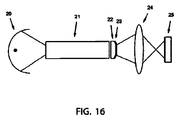
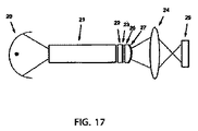
本発明の第7側面によれば、第1プロジェクタ及び第2プロジェクタを含む投影システムによって上記目的が満たされる。第1プロジェクタは、第1ランプと、入力端及び出力端を有する第1統合ロッドであって、入力端を介して第1ランプから光を受け取り出力端において均一な照明を生成するべく構成される第1統合ロッドと、当該統合ロッドの出力端における均一な照明をフィルタリングするべく構成される第1プロジェクタフィルタと、第1空間光変調器チップと、第1プロジェクタフィルタを当該光変調器チップ上に結像させる第1照明システムと、第1射出瞳であって、これを介して第1空間光変調器チップからの光が第1プロジェクタから出る第1射出瞳とを含む。第2プロジェクタは、入力端及び出力端を有する第2統合ロッドであって、入力端を介して第2ランプから光を受け取り出力端において均一な照明を生成するべく構成される第2統合ロッドと、当該統合ロッドの出力端における均一な照明をフィルタリングするべく構成される第2プロジェクタフィルタと、第2空間光変調器チップと、第2プロジェクタフィルタを当該光変調器チップ上に結像させる第2照明システムと、第2射出瞳であって、これを介して第2空間光変調器チップからの光が第2プロジェクタから出る第2射出瞳とを含む。第1プロジェクタフィルタは、第1射出瞳を介して出る光を波長シフトさせるべく構成され、第2プロジェクタフィルタは、第2射出瞳を介して出る光を波長シフトさせるべく構成される。 According to the seventh aspect of the present invention, the above object is satisfied by a projection system including a first projector and a second projector. The first projector is a first integrated rod having a first lamp and an input end and an output end, configured to receive light from the first lamp via the input end and generate uniform illumination at the output end. A first integrated rod, a first projector filter configured to filter uniform illumination at the output end of the integrated rod, a first spatial light modulator chip, and a first projector filter on the light modulator chip A first illumination system to be imaged and a first exit pupil through which light from the first spatial light modulator chip exits the first projector. A second integrated rod having an input end and an output end, the second projector being configured to receive light from the second lamp via the input end and generate uniform illumination at the output end; A second projector filter configured to filter uniform illumination at the output end of the integrated rod, a second spatial light modulator chip, and a second image forming the second projector filter on the light modulator chip. An illumination system and a second exit pupil through which light from the second spatial light modulator chip exits the second projector. The first projector filter is configured to wavelength shift light exiting through the first exit pupil, and the second projector filter is configured to wavelength shift light exiting through the second exit pupil.
第1プロジェクタフィルタは第1通過帯域及び第1保護帯域を画定し、第2プロジェクタフィルタは、第1通過帯域とは重ならない第2通過帯域を画定する。第2保護帯域は第1保護帯域と重なってよい。 The first projector filter defines a first passband and a first guard band, and the second projector filter defines a second passband that does not overlap the first passband. The second guard band may overlap the first guard band.
第1プロジェクタフィルタは第1帯域ストップを画定し、第1プロジェクタはさらに、第1通過帯域及び第1保護帯域の第1統合及び画定の出力端からの均一な照明をフィルタリングするべく構成される第1補助フィルタであって、第1帯域ストップが第1保護帯域とマッチング又はほぼマッチングする第1補助フィルタを含み、第2プロジェクタフィルタは、第1通過帯域とは重ならない第2通過帯域及び第1保護帯域と重なる第2保護帯域を画定する。 The first projector filter defines a first band stop, and the first projector is further configured to filter uniform illumination from the first integrated and defined output end of the first passband and the first guard band. A first auxiliary filter, wherein the first band stop matches or substantially matches the first guard band, and the second projector filter includes a second passband and a first one that do not overlap the first passband A second guard band that overlaps the guard band is defined.
第1プロジェクタフィルタは第1帯域ストップを画定し、第1プロジェクタはさらに、第1通過帯域及び第1保護帯域の第1統合及び画定の出力端からの均一な照明をフィルタリングするべく構成される第1補助フィルタであって、第1帯域ストップは第1保護帯域とマッチング又はほぼマッチングし、第2プロジェクタフィルタは第2帯域ストップを画定する第1補助フィルタを含み、第2プロジェクタはさらに、第1通過帯域とは重ならない第2通過帯域及び第1保護帯域とは重ならない第2保護帯域の第1統合及び画定の出力端からの均一な照明をフィルタリングするべく構成される第2補助フィルタであって、第2帯域ストップが第2保護帯域とマッチング又はほぼマッチングする第2補助フィルタを含む。 The first projector filter defines a first band stop, and the first projector is further configured to filter uniform illumination from the first integrated and defined output end of the first passband and the first guard band. A first subband filter, wherein the first band stop matches or substantially matches the first guard band, the second projector filter includes a first subfilter defining a second band stop, the second projector further includes: A second auxiliary filter configured to filter uniform illumination from a first integrated and defined output of a second passband that does not overlap the passband and a second guardband that does not overlap the first guardband. Thus, the second band stop includes a second auxiliary filter that matches or substantially matches the second guard band.
第2補助フィルタはフラットであり第2均一厚さを有する。第1補助フィルタはフラットであり第1均一厚さを有する。 The second auxiliary filter is flat and has a second uniform thickness. The first auxiliary filter is flat and has a first uniform thickness.
第1プロジェクタフィルタは第1均一厚さを画定し、及び/又は第2プロジェクタフィルタは第2均一厚さを画定する。第1プロジェクタフィルタは第1変化厚さを有し、及び/又は第2プロジェクタフィルタは第2変化厚さを有する。第1プロジェクタフィルタは第1曲率を画定し、及び/又は第2プロジェクタフィルタは第2曲率を画定する。第1プロジェクタフィルタは第1プロジェクタフィルタの第1中心部分に第1フラットエリアを画定し、及び/又は第2プロジェクタフィルタは第2プロジェクタフィルタの第2中心部分に第2フラットエリアを画定する。第1プロジェクタフィルタは第1プロジェクタフィルタの第1周縁部分に第1湾曲形状を画定し、及び/又は第2プロジェクタフィルタは第2プロジェクタフィルタの第2周縁部分に第2湾曲形状を画定する。第1プロジェクタフィルタは第1透明基板、好ましくは第1ガラス基板、に載置され、第2プロジェクタフィルタは第2透明基板、好ましくは第2ガラス基板、に載置される。第1プロジェクタフィルタはダイクロイックであり、及び/又は第2プロジェクタフィルタはダイクロイックである。 The first projector filter defines a first uniform thickness and / or the second projector filter defines a second uniform thickness. The first projector filter has a first varying thickness and / or the second projector filter has a second varying thickness. The first projector filter defines a first curvature and / or the second projector filter defines a second curvature. The first projector filter defines a first flat area in the first central portion of the first projector filter and / or the second projector filter defines a second flat area in the second central portion of the second projector filter. The first projector filter defines a first curved shape at the first peripheral portion of the first projector filter and / or the second projector filter defines a second curved shape at the second peripheral portion of the second projector filter. The first projector filter is placed on a first transparent substrate, preferably a first glass substrate, and the second projector filter is placed on a second transparent substrate, preferably a second glass substrate. The first projector filter is dichroic and / or the second projector filter is dichroic.
第1プロジェクタフィルタは第1統合ロッドの出力端に配置され、及び/又は第2プロジェクタフィルタは第2統合ロッドの出力端に配置される。第1統合ロッドは出力端に第1幅を有する第1アパチャを画定し、第1プロジェクタフィルタは第1幅に等しいか又はほぼ等しい第1半径を有する第1球形面を画定し、及び/又は第2統合ロッドは出力端に第2幅を有する第2アパチャを画定し、第2プロジェクタフィルタは第2幅に等しいか又はほぼ等しい第2半径を有する第2球形面を画定する。 The first projector filter is disposed at the output end of the first integration rod and / or the second projector filter is disposed at the output end of the second integration rod. The first integrating rod defines a first aperture having a first width at the output end, the first projector filter defines a first spherical surface having a first radius equal to or approximately equal to the first width, and / or The second integrating rod defines a second aperture having a second width at the output end, and the second projector filter defines a second spherical surface having a second radius equal to or approximately equal to the second width.
本発明の第12側面によれば、一連の3次元画像を生成するシステムによって上記目的が満たされる。当該システムは、本発明の第1側面に係る方法を繰り返し適用することにより、第1出力画像及び第2出力画像を含む左出力であって当該一連の3次元画像の左透視画像を表す左出力を生成するコンピュータ及び/又は一以上の回路であって、本発明の第1側面に係る方法を繰り返し適用することにより、第1出力画像及び第2出力画像を含む右出力であって当該一連の3次元画像の対応右透視画像を表す右出力を生成するべくさらに構成されるコンピュータ及び/又は一以上の回路と、投影スクリーンと、当該コンピュータ及び/又は一以上の回路に接続され、かつ、当該投影スクリーン上の左出力の第1出力画像を投影するべく構成される左透視第1プロジェクタと、当該コンピュータ及び/又は一以上の回路に接続され、かつ、当該投影スクリーンの右出力の第1出力画像を投影するべく構成される右透視第1プロジェクタと、当該コンピュータ及び/又は一以上の回路に接続され、かつ、当該投影スクリーン上の左出力の第2出力画像と右出力の第2出力画像とを交互に投影するべく構成される左/右透視第2プロジェクタとを含む。 According to the twelfth aspect of the present invention, the above object is satisfied by a system for generating a series of three-dimensional images. The system repeatedly outputs the left output including the first output image and the second output image and representing the left perspective image of the series of three-dimensional images by repeatedly applying the method according to the first aspect of the present invention. A computer and / or one or more circuits that generate a right output including a first output image and a second output image by repeatedly applying the method according to the first aspect of the present invention. A computer and / or one or more circuits further configured to generate a right output representing a corresponding right perspective image of the three-dimensional image, connected to the projection screen, the computer and / or one or more circuits, and A left perspective first projector configured to project a left output first output image on a projection screen, connected to the computer and / or one or more circuits, and A right perspective first projector configured to project a first output image of the right output of the screen, and a second output image of the left output on the projection screen, connected to the computer and / or one or more circuits. And a left / right perspective second projector configured to alternately project a right output second output image.
本発明の第12側面によれば、一連の3次元画像を生成するシステムによって上記目的が満たされる。当該システムは、本発明の第1側面に係る方法を繰り返し適用することにより、第1出力画像及び第2出力画像を含む左出力であって当該一連の3次元画像の左透視画像を表す左出力を生成するコンピュータ及び/又は一以上の回路であって、本発明の第1側面に係る方法を繰り返し適用することにより、第1出力画像及び第2出力画像を含む右出力であって当該一連の3次元画像の対応右透視画像を表す右出力を生成するべくさらに構成されるコンピュータ及び/又は一以上の回路と、投影スクリーンと、当該コンピュータ及び/又は一以上の回路に接続され、かつ、当該投影スクリーン上の左出力の第1出力画像を投影するべく構成される左透視第1プロジェクタと、当該コンピュータ及び/又は一以上の回路に接続され、かつ、当該投影スクリーン上の右出力の第1出力画像を投影するべく構成される右透視第1プロジェクタと、当該コンピュータ及び/又は一以上の回路に接続され、かつ、当該投影スクリーン上の左出力の第2出力画像を投影するべく構成される左透視第2プロジェクタと、当該コンピュータ及び/又は一以上の回路に接続され、かつ、当該投影スクリーン上の右出力の第2出力画像を投影するべく構成される右透視第2プロジェクタとを含む。 According to the twelfth aspect of the present invention, the above object is satisfied by a system for generating a series of three-dimensional images. The system repeatedly outputs the left output including the first output image and the second output image and representing the left perspective image of the series of three-dimensional images by repeatedly applying the method according to the first aspect of the present invention. A computer and / or one or more circuits that generate a right output including a first output image and a second output image by repeatedly applying the method according to the first aspect of the present invention. A computer and / or one or more circuits further configured to generate a right output representing a corresponding right perspective image of the three-dimensional image, connected to the projection screen, the computer and / or one or more circuits, and A left perspective first projector configured to project a left output first output image on a projection screen, connected to the computer and / or one or more circuits, and A right perspective first projector configured to project a right output first output image on the screen, and a second output of the left output on the projection screen connected to the computer and / or one or more circuits; A left fluoroscopic second projector configured to project an image and a right connected to the computer and / or one or more circuits and configured to project a right output second output image on the projection screen And a fluoroscopic second projector.
第12側面及び/又は第13側面において、左透視第1プロジェクタは、当該左透視第1プロジェクタにより投影される光を偏光させる左偏光フィルタを含み、右透視第1プロジェクタは、当該右透視第1プロジェクタにより投影される光を偏光させる右偏光フィルタを含む。左偏光フィルタ及び右偏光フィルタは直交か又はほぼ直交の偏光方向を有する。 In the twelfth aspect and / or the thirteenth aspect, the left fluoroscopic first projector includes a left polarizing filter that polarizes light projected by the left fluoroscopic first projector, and the right fluoroscopic first projector includes the right fluoroscopic first projector. A right polarizing filter for polarizing light projected by the projector; The left and right polarizing filters have orthogonal or nearly orthogonal polarization directions.
左偏光フィルタ及び右偏光フィルタは対向する円偏光方向を有する。投影スクリーンは非偏光解消性である。第12側面及び/又は第13側面に係るシステムはさらに、時間変化偏光ユニットを含む。 The left polarizing filter and the right polarizing filter have opposite circular polarization directions. The projection screen is non-depolarizing. The system according to the twelfth aspect and / or the thirteenth aspect further includes a time-varying polarization unit.
本発明の異なる側面に係る複数実施例が図面に示される。 Multiple embodiments according to different aspects of the invention are illustrated in the drawings.
本発明は、例示的な構成により以下に記載されるが、これらに限られるものとみなされることを意図しない。説明を目的として、グレースケールシステムが使用されて本発明が記載される一方、記載の構成は、三刺激(例えばRGB)カラー投影システムの色平面にも適用できる。また、標準色空間変換技術を使用することにより、他の色空間(例えばYPbPr)を使用する投影システムに対しても使用できる。さらに、ソース画像信号とプロジェクタとの間の、例えば色相調整、黒色点及び白色点等に適合する色補正回路も含まれることは明らかである。さらに、画像投影システムはいくつかの記載で使用される一方、記載の構成は、動画を構成する一シーケンスの静止画上で動作することもできる。本明細書ではモノスコープ投影システムが使用されるが、本発明は、ステレオスコープのアプリケーションに使用される一セットの投影システム、又は別個の左目入力及び右目入力を有するか若しくは二重フレームレート入力を有する動的ステレオスコーププロジェクタにも同様に適用できる。画素値が0から1の範囲で記載される一方、現実的実装においては他の範囲も選択される可能性が高い。複数の操作が別個の回路により行われるように記載される一方、現実的実装においてこれらは、コンピュータメモリ又はグラフィックスカードメモリにソフトウェアアルゴリズム、ルックアップテーブル等として実装される可能性が高い。当業者にとって明らかな、さらなる修正的、付加的、及び代替的構成も本発明の範囲に含まれることが意図される。 The present invention is described below by way of example configurations, but is not intended to be considered as limited thereto. For purposes of illustration, a gray scale system is used to describe the present invention, while the described arrangement is applicable to the color plane of a tristimulus (eg, RGB) color projection system. Further, by using a standard color space conversion technique, it can be used for a projection system using another color space (for example, YPbPr). Further, it is obvious that a color correction circuit adapted to, for example, hue adjustment, black point, white point and the like between the source image signal and the projector is included. In addition, while the image projection system is used in some descriptions, the described configuration can also operate on a sequence of still images that make up a video. Although a monoscope projection system is used herein, the present invention is a set of projection systems used for stereoscope applications, or has separate left-eye and right-eye inputs or has dual frame rate inputs. The present invention can be similarly applied to a dynamic stereoscope projector having the same. While pixel values are described in the range of 0 to 1, in realistic implementation, other ranges are likely to be selected. While multiple operations are described as being performed by separate circuits, in a practical implementation these are likely to be implemented as software algorithms, look-up tables, etc. in computer memory or graphics card memory. Further modifications, additions, and alternative configurations apparent to those skilled in the art are intended to be included within the scope of the present invention.
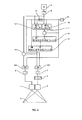
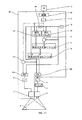
図1は、従来技術の構成の概略図を示す。従来型二重スタックは、実質同一のプロジェクタすなわち第1プロジェクタ1及び第2プロジェクタ2を含む。各々は投影面3に画像を投影し、各々は画像生成器4の符号化ガンマに対応する復号化ガンマ関数を有する。画像生成器4は、一アレイの画素値を含むソース画像信号を出力する。概略図における接続線は画像信号経路を示す。画像生成器の出力が第1プロジェクタ1の入力に及びワーピング回路5の入力に供給される。ワーピング回路5の出力が第2プロジェクタ2の入力に供給される。ワーピング回路5は、第2プロジェクタ2により投影される画像の幾何補正を行う。これにより、当該画像が、プロジェクタ1により投影される画像と整合し、両投影画像間の機械的整合不良が補償される。熱振動等に起因する機械的及び光学的部品の動きを補償するには繰り返しの再較正が必要となる。
FIG. 1 shows a schematic diagram of the configuration of the prior art. The conventional double stack includes substantially the same projector, namely the
図2は、本発明の第1実施例の概略図を示す。図1の構成に対しては、画像スプリット関数が付加されている。画像スプリット関数は、ガンマ復号化回路6、第1ガンマ符号化回路7、第2ガンマ符号化回路8、画像バッファ9、明化画像リミッタ10、第1画像減算回路11、暗化画像リミッタ12、第2画像減算回路13、第1拘束付き平滑化フィルタ14、第2拘束付き平滑化フィルタ15、画像反転回路16、第1画像除算回路101、及び第2画像除算回路102を含み、これらがすべて接続されて当該図面に示されている。
FIG. 2 shows a schematic diagram of a first embodiment of the invention. An image split function is added to the configuration of FIG. The image split function includes a
ガンマ復号化回路6は画像生成器4の符号化ガンマにマッチングされ、第1ガンマ符号化回路7は第2プロジェクタ2の復号化ガンマにマッチングされ、及び、第2ガンマ符号化回路8は第1プロジェクタ1の復号化ガンマにマッチングされる。したがって、ガンマ復号化回路6の出力と、第1ガンマ符号化回路7と、第2ガンマ符号化回路8との間の回路における操作はすべて、一貫したガンマで行われる。このことは、画素値が線形強度を表すことを意味し、投影面3の一ポイントにおいて結果的に得られる重ね合わせ照度は、第1ガンマ符号化回路7に及び第2ガンマ符号化回路8に入力される画像の対応する画素値の合計の関数となる。
The
画像バッファ9は、双方のプロジェクタが均一かつ最大強度の画像を入力に供給する場合に第1プロジェクタ1が投影面3上の対応位置に寄与する照度部分の表示を、各画素値に対して保持するしきい画像Tを格納する。この実施例においては、第1プロジェクタ1及び第2プロジェクタ2は実質同一なので、第1プロジェクタ1はすべての位置において照度の半分に寄与し、Tにおけるすべての画素値は0.5である。この実施例の代替的構成において、プロジェクタが同一ではなく最大照度の空間分布が異なる。この場合Tは、0から1の変化値を備える画素を有する画像となる。
The
画像バッファ9のコンテンツT及びガンマ復号化回路6の出力が、明化リミッタ10に供給される。明化画像リミッタ10は、すべての画素位置において当該2つの入力の高い方にある画像を計算し、その結果を第1画像減算回路11に出力する。第1画像減算回路11はTを減算し、その結果を拘束付き平滑化フィルタ14の下境界画像入力LBに供給する。この画像の画素値は、第1プロジェクタ1が単独では再現することができない強度量を表す。したがって、第2プロジェクタ2の最小強度が対応画素位置において寄与する必要がある。
The content T of the
画像バッファ9のコンテンツTは画像反転回路16に供給され、画像反転回路16の出力は暗化画像リミッタ12に供給される。さらに、ガンマ復号化回路6の出力も暗化画像リミッタ12に供給される。暗化画像リミッタ12は、すべての画素位置において当該2つの入力の低い方にある画像を計算し、その結果を拘束付き平滑化フィルタ14の上境界画像入力UBに出力する。この画像は、第2プロジェクタ2が寄与すべき最大強度、すなわち対応画素位置において第2プロジェクタが寄与できる最大強度により制限される望ましい結果的な画素強度、を表す。
The content T of the
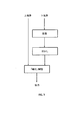
第1拘束付き平滑化フィルタ14は、わずかな高周波成分のみを備える一般に滑らかかつぼけた出力画像を計算する。当該出力画像は、いずれの画素位置においても、下境界画像LBの対応画素値から上境界画像の対応画素値までの範囲内にある画素値を有するように実質的に拘束される。図3は、拘束付き平滑化フィルタ14の例示的構成のプロセスフローチャートを示す。拘束付き平滑化フィルタ14は、下境界入力画像LB上に膨張半径r1を有するグレースケール膨張操作を行う。その後、グレースケール膨張操作の結果上にr1以下のぼかし半径rを有するぼかし操作を行う。その後、ぼかし操作の結果上に上境界入力画像UBを有する暗化画像制限操作を行い、ぼかし操作の結果における画素値を、上境界入力画像UBの対応画素値以下となるように制限する。暗化画像制限操作の結果が第1拘束付き平滑化フィルタの出力となる。代替的に、暗化画像制限操作は省略してもよく、ぼかし操作の結果が第1拘束付き平滑化フィルタの出力とされてよい。膨張半径r1は4画素であり、かつ、ぼかし半径r1’はr1と等しい。代替的に、膨張半径r1は下境界入力画像LBの幅の1/300であり、かつ、ぼかし半径r1’はr1と等しい。ぼかし操作は、標準偏差1/3*r1’を有するガウシアンぼかし操作である。または、ぼかし操作は平均フィルタリング操作である。代替的構成において、第1拘束付き平滑化フィルタ14は、スプラインに基づくか若しくはメンブレンに基づくエンベロープフィルタ又はグロー効果フィルタを含む。
The first constrained smoothing
第1拘束付き平滑化フィルタ14の出力が第2拘束付き平滑化フィルタ15の下境界入力に供給され、画像反転回路16の出力が第2拘束付き平滑化フィルタ15の上境界入力に供給される。第2拘束付き平滑化フィルタ15は、膨張半径r2及びぼかし半径r2’を有する第1拘束付き平滑化フィルタ14と類似する操作を行う。膨張半径r2は2画素であり、かつ、ぼかし半径r2’はr2と等しい。代替的に、膨張半径r2は、第2拘束付き平滑化フィルタ15の下境界入力画像の幅の1/600であり、かつ、ぼかし半径r2’はr2と等しい。代替的構成において、第2拘束付き平滑化フィルタ15はぼかしフィルタに置換される。第2拘束付き平滑化フィルタ15の膨張半径r2は調整可能であり、ぼかし半径r2’は調整された場合のr2に従うように設定される。なお、r2=0かつr2’=0の場合、第2拘束付き平滑化フィルタ15の出力は下境界入力と等しい。すなわち、第1拘束付き平滑化フィルタ14の出力と等しい。
The output of the first constrained smoothing
ガンマ復号化回路6の出力及び第2拘束付き平滑化フィルタ15の出力が画像減算回路13に供給される。画像減算回路13は、第2拘束付き平滑化フィルタ15の出力をガンマ復号化回路6の出力から減算することにより画像を計算する。減算結果が第1画像除算回路101の第1入力に供給される。画像バッファ9からの出力画像Tが第1画像除算回路101の第2入力に供給される。第1画像除算回路101が第1入力を第2入力により除算し、除算結果が第2ガンマ符号化回路8の入力に供給される。したがって、第1画像除算回路101は、第2画像減算回路13の出力画像における、0から対応画素値Tまでの範囲にある画素値を、Tにおける画素値で除算することによりスケール化する。これにより、結果的に出力される画素値は、0から1の範囲にスケール化される。
The output of the
第2拘束付き平滑化フィルタ15の出力画像はさらに第2画像除算回路102の第1入力に供給され、画像反転回路16の出力は第2画像除算回路102の第2入力に供給される。第2画像除算回路102は第1入力を第2入力により除算し、除算結果が第1ガンマ符号化回路7の入力に供給される。したがって、第2画像除算回路102は、第2拘束付き平滑化フィルタ15の出力画像における、0から対応画素値Tの逆数までの範囲にある画素値を、Tにおける画素値の逆数で除算することによりスケール化する。これにより、結果的に出力される画素値は、0から1の範囲にスケール化される。
The output image of the second constrained smoothing
第1ガンマ符号化回路7の出力はワーピング回路5の入力に供給され、ワーピング回路5の出力は第2プロジェクタ2の入力に供給される。第2ガンマ符号化回路8の出力は第1プロジェクタ1の入力に供給される。
The output of the first
代替的な、第1実施例の単純化された構成において、暗化画像リミッタ12は省略してよく、均一かつ最大強度の画像が第1拘束付き平滑化フィルタ14の上境界入力に供給されてよい。
In an alternative, simplified configuration of the first embodiment, the
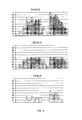
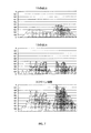
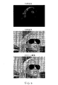
図4は、当該処理の異なるステージにおける一列の画素の例示的部分の値のグラフを示す。図4の第1グラフはガンマ復号化回路6の出力を示し、第2グラフは暗化リミッタ12の出力を示し、及び第3グラフは第1画像減算回路11の出力を示す。
FIG. 4 shows a graph of example portion values for a row of pixels at different stages of the process. The first graph in FIG. 4 shows the output of the
図5は、3画素の膨張半径r1及びr1に実質的に等しいぼかし半径r1’を有する拘束付き平滑化フィルタ14の操作の異なるステージにおける一列の画素の例示的部分の値のグラフを示す。図5の第1グラフにおいて、膨張操作の結果が黒線として示される。下境界入力が暗いグレーで示され、上境界入力が明るいグレーで示される。第2グラフは、ぼかし操作の結果を同様に示し、第3グラフは暗化操作の結果を示す。
FIG. 5 shows a graph of exemplary portion values for a row of pixels at different stages of operation of the constrained smoothing
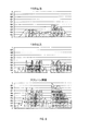
図6は、一列の画素における値の3つの例示的グラフを示す。図6の第1グラフは、r1=3画素かつr2=0であって、r1’がr1と実質的に等しく、r2’がr2に実質的に等しい場合の第2拘束付き平滑化フィルタ15の出力を示す。第2グラフは画像減算回路13の出力を示し、第3グラフは、第2拘束付き平滑化フィルタ15及び画像減算回路13の出力の合計値を示す。上述のように当該合計値は、投影画像の整合が実質完全な場合、当該操作が一貫したガンマで行われることにより、投影面3上にある対応列の画素の結果的な照度に直接変換される。この例においてr2=0の場合、ガンマ符号化回路に対する入力画像の合計は、ガンマ復号化回路6の出力と等しい。したがって、ガンマ復号化回路6は、投影画像の完全な整合を有するガンマ復号化ソース画像であり、投影面3上の結果的な画像は、画像生成器4の出力に実質完全に対応する。この状態は「完全再構成」ということができる。「完全再構成」状態においてのみ機能するこの実施例の代替的構成においては、第2拘束付き平滑化フィルタ15が省略される。
FIG. 6 shows three exemplary graphs of values in a row of pixels. The first graph of FIG. 6 shows the second constrained smoothing
図6の第1グラフが示すように、第2拘束付き平滑化フィルタ15の出力における高空間周波数の量は、ガンマ復号化回路6の出力画像におけるものよりも著しく低い。その結果、従来型二重スタック構成よりも一般に滑らかかつぼかしが与えられた画像が、第2プロジェクタ2により投影される。
As shown in the first graph of FIG. 6, the amount of high spatial frequency in the output of the second constrained smoothing
本発明の第1の利点は、第2プロジェクタ2の滑らかな画像が、投影画像の整合不良を小さくすることにより導入される可視のアーチファクトを低減することにある。多くの場合、従来型二重スタック構成において可視性の高いアーチファクトを導入していたフル画素以上の整合不良が目立たない。
The first advantage of the present invention is that the smooth image of the
しかしながら、図6の第1グラフからわかるように、第2拘束付き平滑化フィルタ15の出力は高周波成分が完全になくなっているわけではない。コントラストが第1プロジェクタ1のコントラスト再現能力に近いか又はこれ以上であるソース画像の高コントラストエッジにおいては、第1拘束付き平滑化フィルタ14への上境界入力及び下境界入力が密接になり、双方の間の滑らかな「湾曲」(又はむしろ面)を常に生成できるとは限らない。投影画像のこれらのエリアは整合不良に対して最も感受性がある。r2を0より高い値に設定することにより、これらのエリアにおいても平滑化を強制して空間周波数成分をさらに低減し、整合不良許容性を増加させることができる。この増加した整合不良許容性の代償は、「完全再構成」達成能力を失い、投影画像の完全整合においてでさえ小さなアーチファクトが導入されることである。当該アーチファクトは、第1プロジェクタ1が再現できるものよりも高いコントラストを有する、ソース画像のエッジまわりのかすかなハローの形態である。したがって、r2を調整することが、「完全再構成」と「高整合不良耐性」との妥協点を画定することになる。
However, as can be seen from the first graph of FIG. 6, the output of the smoothing
図7は図6と同等であるが、ここでは膨張半径r2が2画素であり、かつ、ぼかし半径r2’がr2と実質的に等しい。膨張半径r1は依然3画素であり、かつ、ぼかし半径r1’は依然r1と実質的に等しい。かすかなハローアーチファクトは、下にある合計のグラフにおいて、最高ピークのすぐ左で可視である。幸運なことに、これらのアーチファクトは投影画像において、網膜(側方マスキング)上の神経反応システムにおける側方抑制ゆえに、人間視覚システムにとって認識不可能である。r2が全体的な投影システムのスクリーン上のコントラストにより決定される制限未満である場合、理論的な「完全再構成」は必ずしも必要ではない。所定タイプの投影システムに対するr2の良好な値を決定することは、前列にいる観測者の決定グループに最大コントラストエッジを含むテストパターンを見てもらいr2のランダム値を切り換えて、当該グループのメンバーにエッジシャープネスの点で当該画像を評価するように依頼し、エッジシャープネスの低減に誰も気づかないr2の値を選択することにより行われる。なお、例えば標準的な低域通過フィルタを選択することとは対照的に、第2フィルタリング通過に対しても第2拘束付き平滑化フィルタ15を選択する理由は、この構成が、側方抑制による抑止を受けることがない重要な視覚クルーである水又は葉の反射のような小領域のハイライトにおける照度を保持する点にある。
FIG. 7 is equivalent to FIG. 6, but here the expansion radius r2 is 2 pixels and the blur radius r2 'is substantially equal to r2. The expansion radius r1 is still 3 pixels and the blur radius r1 'is still substantially equal to r1. A faint halo artifact is visible just to the left of the highest peak in the total graph below. Fortunately, these artifacts are unrecognizable to the human visual system in the projected image due to lateral suppression in the neural reaction system on the retina (lateral masking). If r2 is less than the limit determined by the on-screen contrast of the overall projection system, a theoretical “complete reconstruction” is not necessarily required. Determining a good value of r2 for a given type of projection system can be achieved by switching the random value of r2 by having the observer's decision group in the front row look at the test pattern containing the maximum contrast edge and allowing members of that group to This is done by requesting the image to be evaluated in terms of edge sharpness and selecting a value of r2 that no one notices in reducing edge sharpness. In addition, for example, in contrast to selecting a standard low-pass filter, the reason for selecting the second constrained smoothing
図8は、第2拘束付き平滑化フィルタ15の出力の印刷画像を、画像減算回路13の出力の印刷画像とともに示す。また、第2拘束付き平滑化フィルタ15の出力及び画像減算回路13の出力を加算することにより計算された結果的な投影オーバレイ画像のシミュレーションを示す。(ここでの画像には、印刷上観察可能となるようにガンマが適用されている。)
FIG. 8 shows a print image output from the second constrained smoothing
図9は、2画素整合不良により投影された画像の拡大部分の類似するシミュレーションを示す。上の画像は従来型二重スタックの投影シミュレーションであり、下の画像は本発明の第1実施例の投影シミュレーションである。 FIG. 9 shows a similar simulation of an enlarged portion of an image projected due to a two-pixel misalignment. The upper image is a conventional double stack projection simulation, and the lower image is a projection simulation of the first embodiment of the present invention.
本発明の第2の利点は、第2拘束付き平滑化フィルタ15の出力画像が一般に観察可能ではなく、付加的情報が供給されなければ、操作して観察可能な画像にするための十分な詳細情報を保持しないことにある。これは、信号経路及び画像ストレージが暗号化及び物理的な耐不正変更の要求を受けるコピープロテクトされた投影システムにおいて、ワーピング回路5及び第2プロジェクタ2を含む第2拘束付き平滑化フィルタ15の出力からのすべての信号経路が、暗号化され又は物理的に保護される必要がないということを意味する。図10は、デジタルシネマサーバにおける第1実施例を含む一例を示す。耐不正変更保護ハウジング18が、示されたコンポーネントを取り囲む。第2ガンマ符号化回路8の出力は暗号化回路17に供給され、第1プロジェクタ1は、入力画像信号を解読することができるデジタルシネマプロジェクタである。図11は、デジタルシネマプロジェクタに第1実施例を含めた例である。画像生成器4は、暗号化された画像信号を出力するデジタルシネマサーバであり、解読回路19が当該信号を解読し、及び耐不正変更ハウジング18が、示されたコンポーネントを取り囲む。図12は、デジタルシネマサーバであり得る画像生成器4の暗号化出力を解読する画像解読回路18と、画像信号を暗号化して、当該画像信号の解読が可能なデジタルシネマサーバに当該暗号化信号を出力する画像暗号化回路17とを有するスタンドアロンユニットに含まれる第1実施例の一例を示す。耐不正変更ハウジングが、示されたコンポーネントを取り囲む。図9、10、及び11の構成において、第1ガンマ符号化回路7、ワーピング回路5、及び第2プロジェクタ2は、耐不正変更ハウジングの外部にあって非暗号化信号を処理し、現実的実装を相対的に単純なものとする。
The second advantage of the present invention is that the output image of the second constrained smoothing
第1実施例の代替的構成においては、再サンプリング回路が含まれる。再サンプリング回路は、第1ガンマ符号化回路7からの出力画像を低空間解像度に再サンプリングして結果的な再サンプリング画像をワーピング回路5に供給する。ここで、ワーピング回路及び第2プロジェクタ2は第1プロジェクタ1よりも空間解像度が低い。第1ガンマ符号化回路7の出力には高周波成分がほとんど含まれないので、結果的な画質に対する影響はほんのわずかか又はまったくない。
In an alternative configuration of the first embodiment, a resampling circuit is included. The resampling circuit resamples the output image from the first
したがって、本発明の第3の利点は、アップグレードコストが低減され、例えば単一2Kプロジェクタを4K及び増加輝度へアップグレードすることを望む劇場において既存の機器への投資が守られることにある。一般に、第2プロジェクタ2に対する緩やかな要求には、第2プロジェクタ2が第1プロジェクタ1とは完全に異なる非対称構成への可能性が開かれている。当該構成は、従来型二重スタックにとって有用とはならないであろうが第1実施例の構成においてはあまり重要でない、低解像度、タイル状システムのわずかな可視混合エッジ又は輝度差、サポートされない暗号化等のような制限を有するが、しかし、良好な黒レベルのような関連する他の利点を有し、第1実施例の一部として使用されない場合は、会議プレゼンテーション、プラネタリウム星野投影等のような専用アプリケーションを提供するべくすでにインストールされているか又は最適化されている。
Thus, a third advantage of the present invention is that upgrade costs are reduced and investments in existing equipment are preserved, for example, in theaters that want to upgrade a single 2K projector to 4K and increased brightness. In general, the moderate demand for the
第1実施例のさらなる代替的構成において、画像収縮回路が、第1拘束付き平滑化フィルタ14の出力と第2拘束付き平滑化フィルタ15の下境界入力との間に挿入される。ここで、前記画像収縮回路は、第1拘束付き平滑化回路14から受け取られた画像信号に対してグレースケール収縮操作を行う。グレースケール収縮操作の半径R3は0.5画素又は1画素である。この構成は、整合不良に起因する実際のスクリーン上の画素強度の誤差が、人間視覚システムの非線形的性質ゆえに同じ線形強度でも人間の目にとってはあまり気づかれない高輝度領域にシフトするという利点を表す。
In a further alternative arrangement of the first embodiment, an image contraction circuit is inserted between the output of the first constrained smoothing
第1実施例のさらなる代替的構成において、色補正回路が第1画像減算回路11の出力と第1拘束付き平滑化フィルタ14の下境界入力との間に挿入される。前記色補正回路はさらにガンマ復号化回路6の出力に接続されて、第1画像減算回路11から受け取った画像において、第1拘束付き平滑化フィルタ14の出力の画素が、ガンマ復号化回路6から受け取った画像信号の対応画素と実質同一の色相を有するように画素値を加算する。この操作は、(R6,G6,B6)をガンマ復号化回路6の出力の画素色値とし、(R11,G11,B11)を第1画像減算回路11の出力の画素色値とし、Max(x,y,z)を値x、y、及びzの最高値を返す関数を示す場合に、各画素に対して定数K=Max(R11/R6,G11/G6,B11/B6)を計算することと、出力画素色値R’=K*R6,G’=K*G6、及びB’=K*B6を計算して(R’.G’.B’)を第1拘束付き平滑化フィルタ14の下境界入力に出力することとにより行われる。この構成において、双方のプロジェクタから投影される画像の画素色相は同じであり、いくつかの画像において整合不良アーチファクトの可視性が低減される。
In a further alternative arrangement of the first embodiment, a color correction circuit is inserted between the output of the first
第1実施例のさらなる代替的構成において、第1ガンマ符号化回路7からの又は再サンプリング回路からの出力信号が第1媒体に記録され、第2ガンマ符号化回路8の出力が暗号化されて第2媒体に記録され、第1媒体及び第2媒体が同期再生される。第1記録媒体の出力がワーピング回路5に供給され、ワーピング回路5は画像整合に対して較正されて第2プロジェクタ2にワープ出力を供給する。第2媒体の出力はプロジェクタ1に供給される。
In a further alternative arrangement of the first embodiment, the output signal from the first
本発明の第4の利点は、従来型二重スタック構成により導入されるバンディングアーチファクトを低減できることにある。前記投影面3上の異なる結果的強度を多くすることができるため、従来型二重スタックシステムよりも高いダイナミックコントラスト解像度を有するからである。各プロジェクタが、人間視覚システムの丁度可知差異にマッチングされた離散強度ステップを有する従来型二重スタック構成において、投影面3上の結果的なオーバレイ画像は、丁度可知差異を超える離散強度ステップを有し得る。これは可視バンディングをもたらし得る。
A fourth advantage of the present invention is that banding artifacts introduced by the conventional double stack configuration can be reduced. This is because the different resulting intensities on the
本発明の第5の利点は、投影面3上に投影される結果的な重ね合わせ画像を撮像するデジタル画像キャプチャシステムに基づく自動再整合システムが、キャプチャ画像を各プロジェクタに由来する成分に分離して、公開プレゼンテーションにおける一シーケンスのフレームを反復することなしに又は特別な反復トレーニングシーケンスを使用することなしにワーピング回路の再較正を行うことにある。例えば、キャプチャ画像の高周波フィルタリングは、第1プロジェクタ1により投影される画像にのみ関連する画像であって特徴マッチング又はトラッキングを可能とする画像を生成し、第1プロジェクタ1への入力画像に関するキャプチャ画像から第1セットの整合不良ベクトルを特定して当該キャプチャ画像を第1プロジェクタ1と整合するようにワーピングし、その後、第1プロジェクタ1に入力される画像のガンマ復号化バージョンを当該キャプチャ画像のガンマ補正かつゲイン補正バージョンから減算する。これにより、第2プロジェクタ2により投影される画像にのみ関連する画像が得られる。その結果、特徴マッチング又はトラッキングが可能となり、当該キャプチャ画像と第2プロジェクタ2により投影される画像との間の第2セットの整合不良ベクトルが計算され得る。第1及び第2セットの整合不良ベクトルから、第3セットの整合不良ベクトルが計算される。これは、第1プロジェクタ1により投影される画像と第2プロジェクタ2により投影される画像との間の整合不良ベクトルである。第3セットの整合不良ベクトルからワーピング回路5の再較正が行われる。代替的に、RGB投影システムにおいて、例えばグリッドのような幾何パターンであってしきい画像Tの値を超える画素値のみを有する幾何パターンを一の色平面に含み、他の色平面は同じ幾何パターンを含むがしきい画像Tの値未満の画素値を有する単一整合画像が構成される。したがって、各画素位置に対して、プロジェクタ間の相対的な整合不良ベクトルを得てワーピング回路5の再較正を行うことができる。
A fifth advantage of the present invention is that an automatic realignment system based on a digital image capture system that captures the resulting superimposed image projected onto the
付加的に、第1実施例は、プロジェクタの一方が単にソース画像の供給を受ける単一プロジェクタモードに切り換えることができる。この単一プロジェクタモードは、プロジェクタ故障の場合におけるフォールバック操作として機能し、プロジェクタ故障を検出することができる検出システムにより自動的にアクティブにされる。検出回路はプロジェクタの一部に統合されるか、又は、検出回路は、投影面3上に投影される結果的な重ね合わせ画像を撮像するデジタル画像キャプチャシステムに基づく。これにより、ある程度の冗長性がもたらされ、例えば、ランプが切れた場合にシステムは低い輝度ではあるが補正画像を投影し続ける。
Additionally, the first embodiment can switch to a single projector mode where one of the projectors simply receives the source image. This single projector mode functions as a fallback operation in case of projector failure and is automatically activated by a detection system that can detect projector failure. The detection circuit is integrated into a part of the projector or the detection circuit is based on a digital image capture system that captures the resulting superimposed image projected onto the
図18は、特に有利な再整合手順をサポートする第1実施例のさらなる代替的構成を示す。画像バッファ103が整合パターンを保持し、画像加算回路104及び暗化リミッタ105が加えられる。画像バッファ103の出力は画像加算回路104の一方の入力に供給され、拘束付き平滑化フィルタ15の出力は画像加算回路104の他方の入力に供給される。画像加算回路104の出力は暗化リミッタ105の一方の入力に供給され、ガンマ補正回路6の出力は暗化リミッタ105の他方の入力に供給される。暗化リミッタの出力は画像除算回路102の一方の入力に及び画像減算回路13の一方の入力に供給される。これらは図面に示されている。画像バッファ103の出力は、黒画像と整合パターンとの間で切り換えることができる。これにより、整合検出が要求されない場合に整合パターンは有効にオフに切り換わることができる。投影画像に対するこれらの付加的な回路要素の効果は、プロジェクタ2により投影される画像が、拘束付きの画像バッファ103の出力である拘束付き整合パターンに加算されることにある。これにより、各画素位置における当該付加の結果が依然として、ソース画像の対応画素値の強度と等しいか又はこれ未満となる。プロジェクタ1により投影される画像は拘束付き整合画像が減算され、投影面3上には完全な整合性をもって2つの画像が重ね合わせられる。整合パタンは相殺されて不可視となるので、ソース画像のみが可視となる。しかしながら、整合不良が導入されると、整合パターンは、周囲画素よりも低強度及び高強度のパターン部分として可視となる。これにより、任意の現行整合不良の容易かつ正確な視覚検出が可能となる。低強度及び高強度の位置は、整合不良が配向される方向を示す。例えば、整合パターンの一部が周囲よりも明るい画素値すなわち明るいパターンインプリントとして可視であり、かつ、整合パターンの同じ一部が周囲よりも暗い画素値すなわち暗いパターンインプリントとして可視であって、暗いインプリントが明るいインプリントの右下に位置する場合、これはプロジェクタ1が、完全整合が生じる位置に対して右側に及び下エッジ方向に配置されることを示す。このように、整合不良の検出は、投影システムの操作中に実行することができる。補正さえもワーピング回路5の調整により行うことができる。
FIG. 18 shows a further alternative arrangement of the first embodiment that supports a particularly advantageous realignment procedure. The
整合パターンは、例えば、規則的な間隔を有する小さなグラフィック要素を含ませることによって、映写技師にとっては依然有用ではあるが一般の観客にはそれほど目立たないように設計することができる。整合パターンは、グリッド、メッシュ、又は、ドット、十字線、若しくは他のグラフィック要素となる任意の規則若しくは不規則パターンであり、バーコード、セマコード、又は他の識別子を含む。 The matching pattern can be designed to be less noticeable to the general audience, while still useful to the projectionist, for example, by including small graphic elements with regular spacing. A matching pattern is a grid, mesh, or any regular or irregular pattern that becomes a dot, crosshair, or other graphic element, and includes a bar code, sema code, or other identifier.
図19は、図18の構成の例示的信号を示す。第1画像は、加算された可視整合パターンを有する暗化リミッタ105の出力である。第2画像は、減算された可視整合パターンを有する画像減算回路13の出力である。第3画像は、完全整合を有する投影面3上の結果的な重ね合わせ画像である。第4画像は、整合不良が存在する場合の投影面3上の結果的な重ね合わせ画像の一例である。
FIG. 19 shows exemplary signals of the configuration of FIG. The first image is the output of the darkening
第1実施例の複数構成を含むカラー画像投影システムにおいて、第1色平面が図18に示される構成により整合パターンとともに投影され、他の色平面は整合パターンなしで投影される。同じ物理的プロジェクタによって色平面が投影される場合、プロジェクタ及び投影光学系の機械的整合不良が実質同一の色平面に影響を与える。その結果、第1色平面から観察される整合不良情報を使用してすべての色平面の整合不良を検出及び補正することができる。これはさらに、特に整合パターンを有する色平面が青色平面である場合、一般の観客に対する整合パターンの可視性を低減する一方で、映写技師は当該画像を、整合画像を有する色平面と実質同一の色を有する光フィルタを介して観察することができるので、映写技師に対する整合画像の可視性は増加する。 In the color image projection system including a plurality of configurations of the first embodiment, the first color plane is projected together with the matching pattern by the configuration shown in FIG. 18, and the other color planes are projected without the matching pattern. When a color plane is projected by the same physical projector, a mechanical misalignment of the projector and the projection optical system affects substantially the same color plane. As a result, the misalignment information observed from the first color plane can be used to detect and correct misalignments in all color planes. This further reduces the visibility of the alignment pattern to the general audience, especially if the color plane with the alignment pattern is a blue plane, while the projectionist makes the image substantially identical to the color plane with the alignment image. Visibility of the aligned image to the projectionist is increased because it can be viewed through a light filter with color.
映写技師に手作業で画像を観察してもらうのに代えて、カメラが投影面3上に記録された画像を記録して、画像処理システムが整合不良を検出及び補正することができる。画像処理システムは、特徴マッチング又は例えばスケール不変特徴トラッキングのような特徴トラッキングを行うことにより、整合パターン又は整合パターン部分の認識を行うことができる。さらに、カメラは長い露光時間を有し得る。その結果、例えば動画の連続するフレームのような複数の異なる投影画像が一回の露光で画像キャプチャ要素に統合され、すべての非静止画要素にぼかしが与えられるが、静止整合パターンは、整合パターン又は整合パターン部分の認識が容易なように保たれる。例えば、整合パターン又は整合パターン部分は、高域通過フィルタリングにより統合かつぼかしが与えられた画像から分離される。投影される一シーケンスの画像は、カメラの画像キャプチャ要素に後に統合される場合、整合パターン以外の要素のぼかしを増加させるべく前処理することができる。例えばゆっくりとした周期的な動きが一シーケンスの動画の静止シーンに導入されるか、又は、動画の一以上又はすべてのフレームにおいて、例えば青色平面のような色平面の一つにぼかしが与えられる。
Instead of having the projection engineer manually observe the image, the camera records the image recorded on the
それぞれが画像の色平面を投影する第1実施例の複数構成を含むカラー画像投影システムにおいて、付加的色補正回路が含まれ得る。これは、第1拘束付き平滑化フィルタ14の出力の色チャネルにおいて画素値を加算して、第1拘束付き平滑化フィルタ14の出力における画素の色相が、ガンマ復号化回路6の出力における対応画素の色相と実質同一になるようにする。付加的色補正回路は、各画素に対して、ガンマ復号化回路6の出力の対応画素値により除算された第1拘束付き平滑化フィルタ14の出力の画素値である分数値を計算する操作を行う。その後、当該付加的補正回路は、各色平面に対してすなわち第1実施例の複数構成のそれぞれに対して当該分数値の最大値を特定する。当該色平面に対する分数値をガンマ復号化回路6の出力に乗算することにより新たな画素値が計算され、結果的な画素値が第2拘束付き平滑化フィルタ15の入力に供給される。このカラー投影システムの利点は、第1プロジェクタ1から及び第2プロジェクタ2から投影される色相が各画素に対して実質同一となり、整合不良の結果生じる可視アーチファクトをさらに低下させることにある。
In a color image projection system that includes multiple configurations of the first embodiment that each project a color plane of an image, an additional color correction circuit may be included. This is because pixel values are added in the color channel of the output of the first constrained smoothing
特別に有利な構成において、3Dシステムが、第1実施例に係る2つの画像処理回路と、3つのプロジェクタと、2つの定常偏光フィルタと、RealD社のZScreen(登録商標)又はRealD社のZScreenを有するXL偏光ビームスプリッタ構成のような時間変化偏光ユニットと、非偏光解消性投影スクリーンと、偏光子を有するアイウェアを含む。第1実施例に係る第1画像処理回路には3D画像の左透視画像が供給され、1実施例に係る第2画像処理回路には前記3D画像の左透視画像が供給される。第1プロジェクタには前記第1画像処理システムの第2ガンマ符号化回路8の出力が供給され、第1偏光フィルタが前記第1プロジェクタの光源と前記投影スクリーンとの間の光路に挿入される。第2プロジェクタには前記第2画像処理システムの第2ガンマ符号化回路8の出力が供給され、第2偏光フィルタが前記第2プロジェクタの光源と前記投影スクリーンとの間の光路に挿入される。前記第1偏光フィルタ及び前記第2偏光フィルタは実質的な直交偏光方向又は対向する円偏光方向を有し、第3プロジェクタは、前記第1画像処理システムの第1ガンマ符号化回路又は再サンプリング回路の出力及び前記第2画像処理システムの第1ガンマ符号化回路又は再サンプリング回路の出力を交互に投影する。すなわち、一方は左目画像用、他方は右目画像用の2つの別個の投影システムがそれぞれ、高周波画像に対して一のプロジェクタを使用し、低周波画像に対して時分割プロジェクタを共有する。
In a particularly advantageous configuration, the 3D system comprises two image processing circuits according to the first embodiment, three projectors, two stationary polarization filters, and RealD's ZScreen® or RealD's ZScreen. A time-varying polarization unit, such as having an XL polarizing beam splitter configuration, a non-depolarizing projection screen, and eyewear with a polarizer. The first fluoroscopic image of the 3D image is supplied to the first image processing circuit according to the first embodiment, and the left fluoroscopic image of the 3D image is supplied to the second image processing circuit according to the first embodiment. The output of the second
この構成の利点は、第3プロジェクタが、少ない量の高周波成分を有する左及び右透視画像の重ね合わせ画像を交互に投影することにより、このプロジェクタの解像度の点における性能上の要求が緩和されることにある。また、例えばプロジェクタの光出力を実質2倍にする例えばRealD社のXLアダプタのような画像コンバイナを有する偏光ビームスプリッタを利用することにより、ある程度の解像度又は画像シャープネスの代償に基づいてプロジェクタの輝度を最適化することができることにある。ただし、プロジェクタ現実的実装における最大達成可能解像度を制限するという代償がある。このように、4つのプロジェクタでのように同量の光をスクリーンに到達させることが、3つのプロジェクタのみを使用して達成することができる。例えば、7KWキセノンランプをそれぞれ有する3つのプロジェクタを含む3D投影システムが、3D巨大スクリーンを照明するのに十分となり得る7KWランプをそれぞれ有する4つのプロジェクタを含むシステムと同じ輝度をもたらし得る。当該システムは、画像解像度、輝度、画像安定性、コントラスト、ダイナミックレンジ、及びフレームレートのいずれの点でも既存のフィルムベースの巨大スクリーン用3D投影システムに匹敵する。 The advantage of this configuration is that the third projector alternately projects superimposed images of left and right fluoroscopic images having a small amount of high-frequency components, thereby reducing the performance requirement in terms of the resolution of this projector. There is. In addition, for example, by using a polarizing beam splitter having an image combiner, such as the RealD XL adapter, which effectively doubles the projector's light output, the brightness of the projector can be reduced based on the price of some resolution or image sharpness. It can be optimized. However, there is a price to limit the maximum achievable resolution in a realistic projector implementation. Thus, having the same amount of light reaching the screen as with four projectors can be achieved using only three projectors. For example, a 3D projection system that includes three projectors each having a 7KW xenon lamp may provide the same brightness as a system that includes four projectors each having a 7KW lamp that may be sufficient to illuminate a 3D giant screen. The system is comparable to existing film-based giant screen 3D projection systems in terms of image resolution, brightness, image stability, contrast, dynamic range, and frame rate.
図13は、合計4つのオーバレイされたプロジェクタ、すなわち第1左プロジェクタ121、第2左プロジェクタ122、第1右プロジェクタ123、及び第2右プロジェクタ124を有する没入型ステレオスコープ投影構成を示す。第1左プロジェクタ121及び第2左プロジェクタ122は、第1実施例に係る構成の一部であり、ステレオスコープ画像の左ビューを投影する。第1右プロジェクタ123及び第2右プロジェクタ124は、第1実施例に係る構成の一部であり、没入型巨大スクリーンシアターにおける右ビューを投影する。投影面3は、観客の近くに配置されるドーム状スクリーン又は大きなフラットスクリーンである。このため、シアター席125に配置される観客メンバーの視野の大部分が画像で満たさる。観客メンバーはステレオスコープアイウェアを装着する。プロジェクタは、ドーム状スクリーンのエッジ近くに軸外配置され、広角又は魚眼投影光学系を含む。投影光学系は、没入型投影の業界で周知の、観客の前にある「スイートスポット」エリアにおいて画素密度が高くなるように構成される。投影光学系はさらに、画像を垂直方向に引き伸ばして当該ドームの大面積に満たすアナモルフィックアダプタを含む。左目ソース画像及び右目ソース画像の幾何補正を行う付加的ワーピング回路が含められる。ワーピング回路は、ソース画像の色平面のそれぞれに対して個別に作用するので、当該投影光学系の色収差をさらに補償するべく較正することができる。当該構成における第1実施例に係る画像スプリット回路を含むことに代えて、再生システムを含み得る。これは、少なくとも一の記憶媒体に格納された第1実施例に係る画像スプリット回路からの事前に記録された出力を同期的に再現し、再現された出力をプロジェクタへ供給することができる。記憶媒体は、第1セットの資産を含む少なくとも一のハードディスクを含む。第1セットの資産は、第1左プロジェクタ1のための第1信号と第1右プロジェクタ1のための第2信号とを含む。第1信号は、左ソース画像がガンマ復号化回路6の入力に供給されたときの第2ガンマ符号化回路8の記録出力であり、第2信号は第1右プロジェクタ1のためのものである。第2信号は、右ソース画像がガンマ復号化回路6の入力に供給されたときの第2ガンマ符号化回路8の記録出力である。当該ハードディスクはさらに第2セットの資産を含む。第2セットの資産は、第2左プロジェクタのための第3信号と第2右プロジェクタのための第4信号とを含む。第3信号は、左ソース画像がガンマ復号化回路6の入力に供給されたときの第1ガンマ符号化回路7の記録出力である。第4信号は、右ソース画像がガンマ復号化回路6の入力に供給されたときの第1ガンマ符号化回路7の記録出力である。第1セットの資産はステレオスコープデジタルシネマパッケージの形式でハードディスクに格納され、第2セットの資産もステレオスコープデジタルシネマパッケージの形式でハードディスクに格納される。第1セットの資産は、暗号化形式で格納することもできる。再生システムは、暗号化信号を第1左プロジェクタの入力に供給し及び暗号化信号を第1右プロジェクタの入力に供給することができる。さらに、再生システムから第2左プロジェクタへの信号経路に配置される第1ワーピング回路が含められ、再生システムから第2右プロジェクタへの信号経路に配置される第2ワーピング回路が含められ、第1ワーピング回路及び第2ワーピング回路は画像整合を目的として較正される。
FIG. 13 shows an immersive stereoscope projection configuration with a total of four overlaid projectors: a first
図12の構成におけるプロジェクタは、スペクトル分離を使用して左目及び右目ビューを分離する。観客メンバーはダイクロイックスペクトル分離フィルタを有するアイウェアを装着し、プロジェクタはダイクロイックスペクトル分離フィルタを含む。第1左プロジェクタ121及び第2左プロジェクタ122の分離フィルタは実質同一であり、アイウェアの左目分離フィルタは第1左プロジェクタ121及び第2左プロジェクタ122の分離フィルタにマッチングされる。第1右プロジェクタ123及び第2右プロジェクタ124の分離フィルタは実質同一であり、アイウェアの右目分離フィルタは第1右プロジェクタ123及び第2右プロジェクタ124の分離フィルタにマッチングされる。スペクトル分離ステレオスコープ投影は、多くの没入型シネマアプリケーションにおいて魅力的な特別の投影面を必要としないという利点を有する。また、視野の中心部分において非常に良好な画質及びステレオスコープ再現を有するが、視野の中心部分の外側ではアーチファクトを導入するという不利な点を有する。これは、アイウェアのフィルタが、法線方向(垂直方向)ではない角度で当該フィルタに入射する光に対しては、その公称性能と異なるからである。これは、ダイクロイックフィルタの性質に固有の現象である。これらの理由により、スペクトル分離ステレオスコープ投影を目的とする改善されたシステムが以下に提案される。
The projector in the configuration of FIG. 12 separates the left eye and right eye views using spectral separation. Audience members wear eyewear having a dichroic spectral separation filter, and the projector includes a dichroic spectral separation filter. The separation filters of the first
図14は従来技術の一例を示す。第1プロジェクタにおけるランプ20が統合ロッド21に光を放射する。統合ロッド21は、出力端に均一な照明をもたらす。ガラス基板22上に載置されるダイクロイックスペクトル分離フィルタである第1プロジェクタフィルタ23が、照明システム24の実質焦点面にある統合ロッド21の出力部近くに配置される。これにより、第1プロジェクタフィルタ23の画像は実質的に、プロジェクタの空間光変調器チップ25に焦点が合わせられる。第2プロジェクタ(図示せず)も同等に構成されるが、第1プロジェクタフィルタ23と相互排他的な第2プロジェクタフィルタ(図示せず)を有する。第1プロジェクタフィルタ23及び第2プロジェクタフィルタは相互排他的な通過帯域を有し、これらの間には保護帯域と称するスペクトル範囲が存在する。保護帯域においては、第1プロジェクタフィルタ23及び第2プロジェクタフィルタ双方はほとんど透過性がない。アイウェアの左目分離フィルタは、第1プロジェクタフィルタ23の通過帯域を含む一セットの通過帯域を有するダイクロイックフィルタである。アイウェアの右目分離フィルタは、第2プロジェクタフィルタの通過帯域を含む一セットの通過帯域を有するダイクロイックフィルタである。アイウェアの分離フィルタは、頭が鼻からスクリーンに向かって実質直線前方を向いた観客メンバーが観察するときの、当該画像の周縁エリアにある画素から非法線(非垂直)角度で入射する光に対し、部分的に補償するべくわずかに湾曲している。これは、非直交角度で入射する光は、分離フィルタのダイクロイック層間を長い距離移動し、実質法線(垂直)角度で入射する画像中間エリアの画素からの光のフィルタリングと比べ、通過帯域がスペクトルシフトされるフィルタリングを受けるからである。これは、プロジェクタフィルタとのマッチングをもたらし、プロジェクタフィルタの保護帯域により与えられる許容値を超えて低減し、当該画像の周縁部分において色アーチファクト、及び左及び右投影システム間のクロストークのアーチファクト(「ゴースト」)をもたらす。画像の異なる部分からの入射光角度を完全に補償する程度に湾曲した分離フィルタを使用することは通常現実的ではない。これは、アイウェア設計に関する美感上の理由と、両目間の距離が、異なる年齢の集団において著しく変わるからである。画像の周縁部分における残りのアーチファクトを体験することは、あなたの目前に2つのぼやけた穴を有するわずかに色がついた半透明かつ半反射性の材料のシートを、あなたの頭に貼り付けることのように記載できる。穴は画像を完全には覆っておらず、「トンネル視界」の感覚がもたらされる。したがって、画像の周縁部分におけるアーチファクトを低減するさらなる手段が通常採用される。当該手段は、プロジェクタフィルタを予め波長シフトさせて、低減された輝度を代償に保護帯域幅を増加させることを含み、さらには、アイウェアの開眼サイズを低減して入射光の可能な角度範囲を制限することを含む。これにより、シャープなかつ心理学的に快適に許容されるあなたの視野の許容境界が導入されるが、明らかに視野が制限されるという代償がある。しかしながら、没入型シネマアプリケーションに対しては、周縁視野のアーチファクトは完全にはなくならない。
FIG. 14 shows an example of the prior art. The
図15は、図14のシステムの代替的構成を示す。画像の周縁領域における色及びゴーストアーチファクトは、第1プロジェクタフィルタ23及び第2プロジェクタフィルタを、プロジェクタの射出瞳においてスペクトル的にフィルタリングされた光が放出角度の関数として波長シフトされるように修正することにより補償される。第1プロジェクタフィルタ23及び第2プロジェクタフィルタは、光変調器チップの周縁部分における画素上に焦点を結ぶ光が、光変調器チップの中心部分上に焦点を結ぶ光よりも長いダイクロイック層間距離を移動するように、実質同一の曲線により湾曲される。したがって、光変調器チップの周縁部分に焦点を結ぶ光が、光変調器チップの中心部分に焦点を結ぶ光に対して波長シフトされるので、投影画像の周縁部分の画素から放出される光は、投影画像の中心部分の画素から放出されるに対して波長シフトされる。その結果、画像の周縁部分にある画素に対して、プロジェクタフィルタによるフィルタリングとアイ(eye)フィルタのフィルタリングの良好なマッチングが得られる。また、標的観察位置における観客メンバーが観察する場合に、画像の周縁部分にあるより多くの画素が、アイフィルタの通過帯域がプロジェクタフィルタの通過帯域を含むようにアイフィルタによりフィルタリングされる。他の位置に配置される他の観客メンバーは、わずかに補償不足又は補償過剰な画像を観察するが、それでも補償がない場合よりも良好な画像を観察する。第1プロジェクタフィルタ23及び第2プロジェクタフィルタの湾曲は、統合ロッド21のアパチャの幅に等しい半径を有する球形である。フィルタにおいて人間視覚システムにより知覚される、製造上の理由から完全には回避できないわずかな色相変化を補償するべく、ソース画像には通常、電子的色補正が適用される。この色補正は通常、画像エリアにわたり空間的に均一である。その代わり、湾曲フィルタを使用する場合この色補正は、人間視覚システムにおいて均一の色相として知覚される投影画像を達成するべく空間的に不均一となり得る。湾曲フィルタを含むことに代えて、変化する厚さの誘電体層を有するダイクロイックフィルタを含むことができる。
FIG. 15 shows an alternative configuration of the system of FIG. Color and ghost artifacts in the peripheral region of the image modify the
湾曲フィルタで補償された画像を見る体験は記載することが難しいが、「補償なしの体験」よりもある程度快適なようである。わずかに色がついた半透明かつ半反射性の材料のシートのぼやけた穴を、あなたの顔がスクリーンに向かって前方に配向されている場合にこれを通して画像全体が見えるように広げるが、今度は当該シートが依然近いながらもあなたの頭から取り外されるので前方をまっすぐ見る方向から頭をそらせる場合に、当該ぼやけた穴のエッジが、まるで薄いカーテンの一対の穴を通して凝視するように、あなたの視野に入るというように記載することができる。 The experience of viewing an image compensated with a curved filter is difficult to describe, but seems to be somewhat more comfortable than an “uncompensated experience”. Spread the blurry hole in the sheet of slightly colored translucent and semi-reflective material so that the entire image can be seen through it if your face is oriented forward towards the screen, but this time Since the seat is still close but removed from your head, if you deflect your head from the direction of looking straight ahead, the edges of the blurry holes will stare through a pair of holes in a thin curtain. It can be described as entering the field of view.
図16は、第1プロジェクタフィルタ23及び第2プロジェクタフィルタそれぞれが、中心領域にフラットエリアを有し、かつ、上述の画像の周縁エリアのアーチファクトを低減する他の手段によっては許容性が十分でない画像の周縁エリアにのみ湾曲形状を有する代替的構成を示す。プロジェクタフィルタの最適な湾曲は、観客メンバーからスクリーンまでの距離、アイフィルタの湾曲、プロジェクタの照明システムのリレーレンズ焦点距離、主観的な美感上の好み、及び他の因子の関数である。「トンネル視界」と「一対の穴を通しての凝視」との妥協が望ましい。
FIG. 16 shows an image in which each of the
図17は、図14の構成に同等なさらなる代替的構成を示すが、ここでは、第1ガラス基板26上に載置される第1湾曲ノッチフィルタ27が、左プロジェクタにおける第1プロジェクタフィルタ23の前に付加配置され、第2ガラス基板上に載置される第2湾曲ノッチフィルタが、第2プロジェクタにおいて対応して付加される。ノッチフィルタは、保護帯域に実質的にマッチングするノッチを有する。その結果、保護帯域幅は、プロジェクタの射出瞳から出る光の放出角度の関数として広げられる。したがって、観察者が、図14、15、及び16に係る構成において生じる大きな角度に頭を向ける場合、周縁視野におけるアーチファクトが低減され、中心視野におけるゴーストアーチファクトがなくなる。ただし、投影画像の周縁部分における輝度の低減が代償となる。ノッチフィルタは、画像の中心部分にフラットエリアを有する。
FIG. 17 shows a further alternative configuration equivalent to the configuration of FIG. 14, where the first curved notch filter 27 placed on the first glass substrate 26 is replaced by a
本発明は付加的に又は代替的に、入力画像を、しきい値に固定された入力画像である第1画像とその残りである第2画像とに分離する画像処理回路を特徴とする。第2画像が、画素値の部分を第1画像からエッジ周辺の暗いエリアまで動かすことにより平滑化され、第2画像の高周波成分含有量が低減され、同一の2つの画像の合計が入力画像と同じままにされる。入力及び出力においてスケール化及びガンマ補正が行われ、実際の輝度重ね合わせが当該計算に確実に適用される。完全整合により、投影されたオーバレイ画像が入力画像に正確に対応する一方、第2画像の高周波成分は第1画像よりも少なくなる。 The present invention additionally or alternatively features an image processing circuit that separates an input image into a first image that is an input image fixed at a threshold value and a second image that is the remainder. The second image is smoothed by moving the pixel value portion from the first image to the dark area around the edge, the high frequency component content of the second image is reduced, and the sum of the two identical images is Will remain the same. Scaling and gamma correction are performed at the input and output to ensure that the actual luminance overlay is applied to the calculation. With perfect alignment, the projected overlay image corresponds exactly to the input image, while the second image has less high frequency components than the first image.
第1の利点は、本システムが、わずかな整合不良から生じる知覚されるアーチファクトを著しく低減する点にある。人間視覚システムが高周波の誤差よりも低周波成分の誤差に対してはあまり敏感ではないからである。一のプロジェクタが単独で「駆動」できるコントラストよりも高いコントラストを有するエッジが存在する場合にのみ、第2画像は高周波成分を含む。しかしながら、人間視覚システムは、いわゆる空間マスキング効果ゆえに150:1以上のコントラストのエッジ近くでは低空間解像度を示すので、高コントラストエッジにおける整合不良アーチファクトもまた可視性が低減される。第1画像の高周波成分のマスキング効果に起因して十分不可視な程度に穏やかな第2画像の低域通過フィルタリングが、高コントラストエッジにおける整合不良アーチファクトをさらにマスキングするのに役立つ。 The first advantage is that the system significantly reduces perceived artifacts resulting from slight misalignments. This is because the human visual system is less sensitive to low frequency component errors than high frequency errors. The second image contains a high frequency component only if there is an edge that has a higher contrast than a single projector can “drive” by itself. However, because the human visual system exhibits low spatial resolution near edges with a contrast of 150: 1 or higher due to the so-called spatial masking effect, misalignment artifacts at high contrast edges are also reduced in visibility. The low pass filtering of the second image, which is gentle enough to be invisible due to the masking effect of the high frequency components of the first image, helps to further mask misalignment artifacts at high contrast edges.
第2の利点は、カメラベースの自動整合システムが、特別な較正シーケンス実行の必要性なしに、フィルム投影中ずっと周期的に、当該フィルムの画像に基づいて再整合を行うことができる点にある。プロジェクタは同一の画像を投影するわけではないので、記録されたスクリーン上の画像から第1及び第2画像を分離することができる。また、これらの画像から、今度は幾何補正(ワーピング)による電子的再整合を目的として使用することができる整合不良情報を計算することができる。 A second advantage is that the camera-based automatic alignment system can perform realignment based on the image of the film periodically during film projection without the need for special calibration sequences. . Since the projector does not project the same image, the first and second images can be separated from the recorded image on the screen. Also, misalignment information that can be used for the purpose of electronic realignment by geometric correction (warping) can be calculated from these images.
第3の利点は、単一プロジェクタ2Kシステムを、4Kプロジェクタを付加することによって、増加した輝度かつ4K解像度にアップグレードすることができる点にある。第2画像の不可視の穏やかな低域通過フィルタリングが可能なので、低解像度プロジェクタを第2画像に対して使用して、第1プロジェクタのフル高精細度の外見を維持することができる(高輝度のみ)。第4の利点は、本システムの結果的な輝度解像度が、高ダイナミックレンジ投影システムにとって重要となり得る単一プロジェクタのそれよりも高い点にある。 A third advantage is that a single projector 2K system can be upgraded to increased brightness and 4K resolution by adding a 4K projector. Since invisible gentle low-pass filtering of the second image is possible, a low resolution projector can be used for the second image to maintain the full high definition appearance of the first projector (high luminance only ). A fourth advantage is that the resulting luminance resolution of the system is higher than that of a single projector, which can be important for high dynamic range projection systems.
本発明は、付加的に又は代替的に以下のポイントを特徴とする。 The present invention additionally or alternatively is characterized by the following points.
1.画像投影システムであって、2つの画像プロジェクタすなわち第1プロジェクタ及び第2プロジェクタを含み、前記第1プロジェクタ及び前記第2プロジェクタはオーバレイ画像を投影面上に投影し、重ね合わせ画像をもたらす。本システムはさらに第1画像処理回路を含む。これは入力画像を2つの画像に分離する。すなわち、第1プロジェクタ画像が前記第1プロジェクタへ入力され、第2プロジェクタ画像が前記第2プロジェクタに入力される。その結果、前記第1プロジェクタが前記第1プロジェクタ画像を投影して前記第2プロジェクタが前記第2プロジェクタ画像を投影している場合、投影面上に形成されるオーバレイ画像は、実質的に前記入力画像対応し、前記第2プロジェクタ画像における高空間周波数の量が前記第1プロジェクタ画像におけるものよりも少ない。 1. An image projection system comprising two image projectors, a first projector and a second projector, wherein the first projector and the second projector project an overlay image onto a projection surface, resulting in a superimposed image. The system further includes a first image processing circuit. This separates the input image into two images. That is, the first projector image is input to the first projector, and the second projector image is input to the second projector. As a result, when the first projector projects the first projector image and the second projector projects the second projector image, the overlay image formed on the projection surface is substantially the input. Corresponding to an image, the amount of high spatial frequency in the second projector image is less than in the first projector image.
2.ポイント1に記載の画像投影システムであって、色補正回路が前記プロジェクタ双方の入力に付加され、画素値と投影色平面輝度との間の結果的なプロジェクタ伝達関数が実質的に線形かつ同一となるように較正される。これにより、表示面上のポイントにおける結果的な投影色平面輝度が実質的に、前記第1プロジェクタ画像の対応画素値と前記第2プロジェクタ画像の対応画素値との和の関数となる。このとき、前記第1プロジェクタ画像の前記対応画素値が0からB1の範囲内にあり、かつ、前記第2プロジェクタ画像の前記対応画素値が0からB2の範囲内にある。ここでB1は前記第1プロジェクタの最大色平面輝度に対応する画素値であり、B2は前記第2プロジェクタの最大色平面輝度に対応する画素値であり、前記第2プロジェクタ画像の計算は、入力画像の実質すべての画素の各画素値に対しB1を超える値を計算することを含み、前記第1プロジェクタ画像は、前記第2プロジェクタ画像を前記入力画像から減算することにより計算される。ここで、前記入力画像の画素値は0からBの範囲内にあり、B=B1+B2が結果的な重ね合わせ画像の最大色平面輝度に対応する画素値となる。
2. The image projection system of
3.ポイント2に記載の画像投影システムであって、前記第2プロジェクタ画像の前記計算はさらに、前記第2プロジェクタ画像の高周波成分が低減されるように、前記第2プロジェクタ画像の画素値に量を加算する平滑化プロセスを含む。ここで、前記量はゼロと前記第1プロジェクタ画像の対応画素値以内に制限される。
3. The image projection system according to
4.ポイント3に記載の画像投影システムであって、前記平滑化プロセスは、前記第2プロジェクタ画像のエッジにハローを加算することを含む。ここで、ハローは当該エッジの暗い側に延びて当該エッジから距離が増すにつれて次第にフェードする。
4). 4. The image projection system according to
5. ポイント3又は4に記載の画像投影システムであって、前記平滑化プロセスは、前記第2プロジェクタ画像の各色平面に適用される重み付きグレースケール膨張を含む。ここで、前記重み付きグレースケール膨張は、構成要素Dによるグレースケール膨張として定義され、入力画素は第1にフィルタリングカーネルFの要素により乗算される。
5. 5. The image projection system according to
6.ポイント1から5に記載の画像投影システムであって、畳み込みカーネルLを有する低域通過フィルタ、又は前記第1画像処理回路と前記第2プロジェクタとの間に挿入される他の平滑化フィルタをさらに含む。
6). 6. The image projection system according to
7.ポイント1から6に記載の画像投影システムであって、前記第2プロジェクタは、前記第1プロジェクタよりも低い空間解像度を有する。
7). 7. The image projection system according to
8.ポイント5から7に記載の画像投影システムであって、グレースケール膨張構成要素Dは、画像幅の0.2%の半径を有する円板形状要素である。フィルタリングカーネルFは、画像幅の0.2%の半径を有する距離関数である。畳み込みカーネルLは、画像幅の0.1%を有するガウシアンカーネルである。
8). The image projection system according to
9.ポイント1から8に記載の画像投影システムであって、前記投影面上の前記結果的な投影画像の画像を記録することができる少なくとも一つのカメラと、前記カメラにより記録された画像において前記第1プロジェクタ画像に由来する第1セットの特徴を隔離し、かつ、前記カメラにより記録された前記画像の前記第2プロジェクタ画像に由来する第2セットの特徴を隔離すること、並びに、前記第1セットの特徴及び前記第2セットの特徴を前記入力画像の特徴に空間相関させて前記相関から空間整合不良情報を計算することができる第2画像処理回路とを含む自動整合システムをさらに含み、さらに、前記整合不良情報に基づいて、前記第1プロジェクタ画像及び前記第2プロジェクタ画像の少なくとも一方を、前記第1投影画像及び前記第2投影画像が幾何学的に整合されるように幾何補正することができる第3画像処理回路を含む。
9. 9. The image projection system according to
10.ポイント9に記載の画像投影システムであって、前記第2画像処理回路は、前記記録された画像から、前記表示面上のオーバレイ画像の画素値と色平面輝度との間の伝達関数が前記プロジェクタ伝達関数に実質同一となるように較正される適合記録画像を生成する色補正回路を含む。前記第2画像処理回路は、TをB1以下とした場合に前記適合記録画像のすべての画素値がしきい値T未満となる少なくとも一つの低輝度エリアを特定しようとして、前記低輝度エリア内の少なくとも一つの特徴マッチングエリアにおいて、前記第1プロジェクタ画像との第1セットの特徴のマッチング操作を行い、結果的に第1セットのオフセットベクトルを得る。前記第2画像処理回路は、前記第1セットのオフセットベクトルに基づいて前記適合記録画像の幾何補正を行うことができる。その結果、幾何補正された適合記録画像は前記入力画像と整合される。前記第2画像処理回路は、前記第1プロジェクタ画像を前記幾何補正された適合記録画像から減算し、その結果的な画像に基づき少なくとも一つのエリアにおいて、前記第2プロジェクタ画像との第2セットの特徴のマッチング操作を行い、結果的に第2セットのオフセットベクトルを得る。前記第3画像処理回路は、前記第1セット及び前記第2セットのオフセットベクトルに基づいて、前記第2プロジェクタ画像及び前記第2プロジェクタ画像の少なくとも一方を、前記第1プロジェクタ投影画像及び前記第2投影画像が実質的に幾何学的に整合されるように幾何補正を行うことができる。前記特徴のマッチング操作は、テンプレートマッチング操作、スケール不変特徴トラッキング操作、又は業界周知の他の任意の特徴トラッキング操作である。
10. 10. The image projection system according to
11.ポイント9及び10に記載の画像投影システムであって、前記自動整合システムは、動画、生中継、静止画像、又は他のコンテンツのプレゼンテーション中に、投影中に生じる幾何学的整合不良を低減するべく繰り返しサイクルを行う。
11. 11. An image projection system according to
12.ポイント1から11に記載の画像投影システムであって、2つを超えるプロジェクタがオーバレイ画像を投影し、前記第1画像処理回路が2つを超える画像を出力し、各々は異なる量の空間周波数を有し、前記第2画像処理回路は、前記プロジェクタそれぞれに由来する前記記録された画像の特徴を隔離することができる。
12 12. The image projection system according to
13.ポイント1から12に記載の画像投影システムであって、技術的記載に含まれるか又は当業者にとって明らかな任意の修正及び構成をさらに含む。
13. The image projection system according to
本発明は付加的に又は代替的に以下の付加ポイントを特徴とする。 The invention additionally or alternatively features the following additional points.
1.画像投影システムであって、実質的に半球形ドーム形状の投影面と、前記ドーム形状の投影面のエッジ近くに配置される少なくとも一つの画像プロジェクタとを含む。前記画像プロジェクタは、前記ドーム形状の投影面の内側に画像を投影し、投影画像は、前記ドーム形状の投影面の少なくとも70%を覆う。当該システムは、広角投影対物レンズ、魚眼投影対物レンズ、広角コンバージョンレンズ、広角コンバージョンミラー、逆アフォーカル光学系若しくはレトロフォーカス光学系、又はこれらの任意の組み合わせを含み、さらに、入力画像の幾何補正をして補正された出力画像を前記プロジェクタの入力に送る第1画像処理回路を含む。 1. An image projection system comprising a substantially hemispherical dome-shaped projection surface and at least one image projector disposed near an edge of the dome-shaped projection surface. The image projector projects an image inside the dome-shaped projection surface, and the projected image covers at least 70% of the dome-shaped projection surface. The system includes a wide-angle projection objective, a fish-eye projection objective, a wide-angle conversion lens, a wide-angle conversion mirror, a reverse afocal optical system or a retrofocus optical system, or any combination thereof, and geometric correction of the input image And a first image processing circuit for sending the corrected output image to the input of the projector.
2.付加ポイント1に記載の画像投影システムであって、画像形成要素とスクリーンとの間の光路に配置される少なくとも一つのプリズムを含むアナモルフィックアダプタをさらに含む。前記アナモルフィックアダプタは、前記画像を一方向に引き伸ばす。
2. The image projection system according to
3.付加ポイント1又は2に記載の画像投影システムであって、前記第1画像処理回路は、前記投影画像が、前記半球形ドーム形状の投影面の実質中心に配置される魚眼プロジェクタからの投影画像と実質同一の幾何学構成を有するように較正される。このとき、前記入力画像は前記魚眼プロジェクタに入力される。
3. 3. The image projection system according to
4.付加ポイント1から3に記載の画像投影システムであって、前記第1画像処理回路は、前記入力画像の各色平面の別個の幾何補正を行うことができる。前記第1画像処理回路は、前記幾何補正が前記画像投影システムの光学要素における色収差を補償するように較正される。
4). The image projection system according to any one of
5.付加ポイント1から4に記載の画像投影システムであって、前記ドーム形状の投影面に位置する少なくとも一つのエリアは、前記投影画像の平均空間解像度よりも高い空間解像度を有する。前記入力画像は、前記補正された出力画像よりも高い空間解像度を有する。前記画像処理回路は実質的に、できる限り多くの空間解像度を前記入力画像から前記出力画像まで保持する。
5. The image projection system according to any one of
6.付加ポイント1から5に記載の画像投影システムであって、前記補正された出力画像から反射誤差を計算することができる第2画像処理回路をさらに含む。前記反射誤差画像は、前記入力画像が前記プロジェクタにより表示面上に投影されるとした場合に、表示面上の各位置において当該表示面の他の部分から散乱により受け取られる反射光全体の推定である。前記反射誤差画像は、一セットのスクリーン測定値に基づいて計算される。前記反射誤差画像は、ラジオシティ計算により計算される。前記画像処理回路は実質的に、前記反射誤差画像を前記入力画像(ゼロに設定される負の値)から減算する。その結果、前記プロジェクタの入力に送られる補償画像が得られる。
6). The image projection system according to any one of
7.付加ポイント6に記載の画像投影システムであって、前記反射誤差画像の減算によっては反射光の完全な相殺が達成できない前記補償画像のエリアに局所的コントラスト向上が適用される。
7). The image projection system according to
8.付加ポイント7に記載の画像投影システムであって、残余誤差画像が、前記反射誤差画像と前記補償画像の前記補正された出力画像からの減算結果との差として計算される。コントラストが向上された補償画像が、局所的コントラスト向上により前記補償画像から計算される。前記残余誤差画像は、低域通過フィルタリングがされた後に、前記補償画像と前記コントラストが向上された補償画像との間のキー付け操作においてキーとして使用される。キー付け操作の結果的画像は、前記プロジェクタの入力に送られる。
8). In the image projection system according to the
9.付加ポイント7又は8に記載の画像投影システムであって、前記局所的コントラスト向上は、不鮮明マスク操作又は局所トーンマッピング操作である。
9. The image projection system according to
10.付加ポイント1から9に記載の画像投影システムであって、技術的記載に含まれるか又は当業者にとって明らかな任意の修正及び構成をさらに含む。
10. The image projection system according to
Claims (15)
画像処理回路によって、各画素が一定の画素値を有する複数画素を含む原画像を受け取ることと、
前記画像処理回路によって、前記複数画素の各画素のしきい値を受け取ることであって、各しきい値は、前記第1プロジェクタが投影する各画素の照度の、前記第1プロジェクタ及び前記第2プロジェクタが投影する対応画素の最大照度に対する割合を表すことと、
前記画像処理回路によって、前記複数画素の各画素に対する逆しきい値を生成することであって、前記逆しきい値は最大しきい値から各対応画素に対する前記しきい値を減算することによって決定されることと、
前記画像処理回路によって、拘束付き平滑化フィルタリングプロセスを適用することと
を含み、
前記拘束付き平滑化フィルタリングプロセスは、
前記拘束付き平滑化フィルタリングプロセスに上境界画像及び下境界画像を入力することであって、前記上境界画像は、前記原画像の最小照度の画素値である第1最小照度値及び対応する逆しきい値の小さい方の値から決定された複数の上境界画素から形成され、前記下境界画像は、前記原画像の最大照度の画素値である第1最大照度値及び対応するしきい値の大きい方の値から前記対応するしきい値が減算されて決定された複数の下境界画素から形成されることと、
前記拘束付き平滑化フィルタリングプロセスに入力された前記下境界画像を一定の膨張半径に基づく膨張操作によって膨張させて、膨張された画像を生成することと、
前記膨張半径に関連付けられたぼかし半径に基づくぼかし操作によって前記膨張された画像をぼかして拘束付き平滑化フィルタリング出力画像を生成することであって、前記拘束付き平滑化フィルタリング出力画像は、任意の画素位置に拘束され、前記原画像よりも高周波成分が低減され、及び、前記下境界画像の対応画素値と前記上境界画像の対応画素値との間にある画定された画素値範囲を有することと、
前記拘束付き平滑化フィルタリング出力画像を前記第2画像として前記拘束付き平滑化フィルタリングプロセスから出力することと、
前記原画像から前記第2画像を減算して前記第1画像を生成することと、
前記第1画像及び前記第2画像を出力することであって、前記第1画像は、前記拘束付き平滑化フィルタリングプロセスに基づく前記第2画像とは異なる空間周波数成分を有することと、
前記第1画像を前記第1プロジェクタにより表面上に投影することと、
前記第2画像を前記第2プロジェクタにより前記表面上に投影することと
を含む方法。 A method of generating a first image and a second image projected by a first projector and a second projector,
Receiving an original image including a plurality of pixels , each pixel having a constant pixel value, by an image processing circuit;
By the image processing circuit, wherein the method comprising: receiving a plurality of pixels threshold of each pixel of each threshold, the illuminance of each pixel of the first projector is projecting, the first projector and the second Expressing the ratio of the corresponding pixels projected by the projector to the maximum illuminance ,
Generating an inverse threshold value for each pixel of the plurality of pixels by the image processing circuit, wherein the inverse threshold value is determined by subtracting the threshold value for each corresponding pixel from a maximum threshold value; And
Applying a constrained smoothing filtering process by the image processing circuit;
The constrained smoothing filtering process comprises:
The method comprising: inputting the upper border image and the lower boundary image before Symbol constrained smoothing filtering process, the upper boundary image, the first minimum illuminance value and the corresponding inverse the the pixel value of the minimum illuminance of the original image is formed from a plurality of upper boundary pixels determined from the value of the smaller threshold, the lower boundary image of the previous SL first maximum illuminance value and the corresponding threshold is a pixel value of the maximum illumination intensity of the original image and Rukoto formed from the lower boundary pixels plurality larger value or found before SL corresponding threshold of has been determined is subtracted,
Expanding the lower boundary image input to the constrained smoothing filtering process by an expansion operation based on a constant expansion radius to generate an expanded image;
The constrained smoothing filtering output image is generated by blurring the dilated image based on a blur operation based on a blur radius associated with the dilation radius, and generating a constrained smoothing filtering output image. Having a defined pixel value range that is constrained by position, reduced in high frequency components than the original image, and located between the corresponding pixel value of the lower boundary image and the corresponding pixel value of the upper boundary image; ,
And outputting from the constrained smoothing filtering process the Constrained smooth filtering the output image as the second image,
Subtracting the second image from the original image to generate the first image;
The method comprising: outputting the first image and the second image, the first image, and have a different spatial frequency components and rather based on the constrained smoothing filtering process the second image,
Projecting the first image onto a surface by the first projector;
Projecting the second image onto the surface by the second projector.
前記画像処理回路によって、前記第2画像を投影する前に前記第2画像をガンマ符号化することと
をさらに含む、請求項1に記載の方法。 Gamma-encoding the first image before projecting the first image by the image processing circuit;
The method of claim 1, further comprising: gamma encoding the second image before projecting the second image by the image processing circuit.
画像処理回路と、
第1プロジェクタと、
第2プロジェクタと、
スクリーンと
を含み、
前記画像処理回路は、
各画素が一定の画素値を有する複数画素を含む原画像を受け取ることと、
前記複数画素の各画素のしきい値を受け取ることであって、各しきい値は、前記第1プロジェクタ及び前記第2プロジェクタが投影する各画素の最大照度に対する前記第1プロジェクタが投影する照度の割合を表すことと、
前記複数画素の各画素に対する逆しきい値を生成することであって、前記逆しきい値は最大しきい値から各対応画素に対する前記しきい値を減算することによって決定されることと、
拘束付き平滑化フィルタリングプロセスを適用することと
を行うべく構成され、
前記拘束付き平滑化フィルタリングプロセスは、
前記拘束付き平滑化フィルタリングプロセスに上境界画像及び下境界画像を入力することであって、前記上境界画像は、前記原画像の最小照度の画素値である第1最小照度値及び対応する逆しきい値の小さい方の値から決定された複数の上境界画素から形成され、前記下境界画像は、前記原画像の最大照度の画素値である第1最大照度値及び対応するしきい値の大きい方の照度値から前記対応するしきい値が減算されて決定された複数の下境界画素から形成されることと、
前記拘束付き平滑化フィルタリングプロセスに入力された前記下境界画像を一定の膨張半径に基づく膨張操作によって膨張させて、膨張された画像を生成することと、
前記膨張半径に関連付けられたぼかし半径に基づくぼかし操作によって前記膨張された画像をぼかして拘束付き平滑化フィルタリング出力画像を生成することであって、前記拘束付き平滑化フィルタリング出力画像は、任意の画素位置に拘束され、前記原画像よりも高周波成分が低減され、及び、前記下境界画像の対応画素値と前記上境界画像の対応画素値との間にある画定された画素値範囲を有することと、
前記拘束付き平滑化フィルタリング出力画像を第2画像として前記拘束付き平滑化フィルタリングプロセスから出力することと、
前記原画像から前記第2画像を減算して第1画像を生成することと、
前記第1画像及び前記第2画像を出力することであって、前記第1画像及び前記第2画像は、前記拘束付き平滑化フィルタリングプロセスに基づいて異なることと、
前記第2画像を幾何補正することによりワープ画像を生成することと
を含み、
前記第1プロジェクタは前記第1画像を投影し、
前記第2プロジェクタは前記ワープ画像を投影し、
前記第1プロジェクタにより投影される前記第1画像は、前記スクリーン上において、前記第2プロジェクタにより投影される前記ワープ画像と重ね合わせられかつ幾何学的に整合されるように構成される画像投影システム。 An image projection system,
An image processing circuit;
A first projector;
A second projector;
Including screen and
The image processing circuit includes:
Receiving an original image comprising a plurality of pixels, each pixel having a constant pixel value;
The method comprising: receiving a threshold value of each pixel of the plurality of pixels, each threshold, the first projector to the maximum illumination intensity of each pixel of the first projector and the second projector projects the illumination to be projected Expressing the percentage,
Generating an inverse threshold for each pixel of the plurality of pixels, wherein the inverse threshold is determined by subtracting the threshold for each corresponding pixel from a maximum threshold;
Applying a constrained smoothing filtering process, and
The constrained smoothing filtering process comprises :
The method comprising: inputting the upper border image and the lower boundary image before Symbol constrained smoothing filtering process, the upper boundary image, the first minimum illuminance value and the corresponding inverse the the pixel value of the minimum illuminance of the original image is formed from a plurality of upper boundary pixels determined from the value of the smaller threshold, the lower boundary image of the previous SL first maximum illuminance value and the corresponding threshold is a pixel value of the maximum illumination intensity of the original image Write a Rukoto formed from a plurality of bottom border pixels the corresponding threshold value from the illuminance value was determined by subtracting the large,
Expanding the lower boundary image input to the constrained smoothing filtering process by an expansion operation based on a constant expansion radius to generate an expanded image;
The constrained smoothing filtering output image is generated by blurring the dilated image based on a blur operation based on a blur radius associated with the dilation radius, and generating a constrained smoothing filtering output image. Having a defined pixel value range that is constrained by position, reduced in high frequency components than the original image, and located between the corresponding pixel value of the lower boundary image and the corresponding pixel value of the upper boundary image ; ,
And outputting from the constrained smoothing filtering process the Constrained smooth filtering the output image as the second image,
Generating a first image by subtracting the second image from the original image,
Outputting the first image and the second image, wherein the first image and the second image are different based on the constrained smoothing filtering process ;
And a generating a warped image by geometric correction previous SL second image,
The first projector projects the first image;
The second projector projects the warped image;
The image projection system configured such that the first image projected by the first projector is superimposed on the screen and geometrically aligned with the warp image projected by the second projector. .
前記第1画像とは異なる空間周波数成分を有する第2画像を投影し、投影面上において前記第1画像とオーバレイさせる第2プロジェクタと、
前記第1画像及び前記第2画像を生成するべく構成される画像処理回路と
を含み、
前記第1画像及び前記第2画像の生成は、前記画像処理回路が、
各画素が一定の画素値を有する複数画素を含む原画像を受け取ることと、
前記複数画素の各画素のしきい値を受け取ることであって、各しきい値は、前記第1プロジェクタ及び前記第2プロジェクタが投影する各画素の最大照度に対する前記第1プロジェクタが投影する各画素の照度の割合を表すことと、
前記複数画素の各画素に対する逆しきい値を生成することであって、前記逆しきい値は最大しきい値から各対応画素に対する前記しきい値を減算することによって決定されることと、
拘束付き平滑化フィルタリングプロセスを適用することと
を含み、
前記拘束付き平滑化フィルタリングプロセスは、
前記拘束付き平滑化フィルタリングプロセスに上境界画像及び下境界画像を入力することであって、前記上境界画像は、前記原画像の最小照度の画素値である第1最小照度値及び対応する逆しきい値の小さい方の値から決定された複数の上境界画素から形成され、前記下境界画像は、前記原画像の最大照度の画素値である第1最大照度値及び対応するしきい値の大きい方の照度値から前記対応するしきい値が減算されて決定された複数の下境界画素から形成されることと、
前記拘束付き平滑化フィルタリングプロセスに入力された前記下境界画像を一定の膨張半径に基づく膨張操作によって入力画像を膨張させて、膨張された画像を生成することと、
前記膨張半径に関連付けられたぼかし半径に基づくぼかし操作によって前記膨張された画像をぼかして拘束付き平滑化フィルタリング出力画像を生成することであって、前記拘束付き平滑化フィルタリング出力画像は、任意の画素位置に拘束され、前記原画像よりも高周波成分が低減され、及び前記下境界画像の対応画素値と前記上境界画像の対応画素値との間にある画定された画素値範囲を有することと、
前記拘束付き平滑フィルタリング出力画像を前記第2画像として前記拘束付き平滑化フィルタリングプロセスから出力することと、
前記原画像から前記第2画像を減算して前記第1画像を生成することと、
前記第1画像及び前記第2画像を出力することと
によって行われる画像投影システム。 A first projector for projecting a first image;
A second projector that projects a second image having a spatial frequency component different from that of the first image and overlays the first image on the projection plane;
An image processing circuit configured to generate the first image and the second image,
The image processing circuit generates the first image and the second image.
Receiving an original image comprising a plurality of pixels, each pixel having a constant pixel value;
The method comprising: receiving a threshold value of each pixel of the plurality of pixels, each threshold, each pixel of the first projector to the maximum illumination intensity of each pixel of the first projector and the second projector is projected to the projection Representing the percentage of illuminance of
Generating an inverse threshold for each pixel of the plurality of pixels, wherein the inverse threshold is determined by subtracting the threshold for each corresponding pixel from a maximum threshold;
Applying a constrained smoothing filtering process; and
The constrained smoothing filtering process comprises :
The method comprising: inputting the upper border image and the lower boundary image before Symbol constrained smoothing filtering process, the upper boundary image, the first minimum illuminance value and the corresponding inverse the the pixel value of the minimum illuminance of the original image is formed from a plurality of upper boundary pixels determined from the value of the smaller threshold, the lower boundary image of the previous SL first maximum illuminance value and the corresponding threshold is a pixel value of the maximum illumination intensity of the original image Write a Rukoto formed from a plurality of bottom border pixels the corresponding threshold value from the illuminance value was determined by subtracting the large,
Dilating the lower boundary image input to the constrained smoothing filtering process by an expansion operation based on a constant expansion radius to generate an expanded image;
The constrained smoothing filtering output image is generated by blurring the dilated image based on a blur operation based on a blur radius associated with the dilation radius, and generating a constrained smoothing filtering output image. Having a defined pixel value range that is constrained to a position, has a higher frequency component than the original image, and is between a corresponding pixel value of the lower boundary image and a corresponding pixel value of the upper boundary image ;
And outputting from the constrained smoothing filtering process the Constrained smoothing filtering the output image as the second image,
Subtracting the second image from the original image to generate the first image;
Image projection system which is performed by the method comprising: outputting the first image and the second image.
前記第1プロジェクタ及び前記第2プロジェクタの照度限度内にある画素値を有する前記第1画像及び前記第2画像を生成し、並びに
前記拘束付き平滑化フィルタリングプロセスに基づいて前記第1画像とは異なる空間周波数成分を有する前記第2画像を生成する
べく構成される、請求項13に記載の画像投影システム。 The image processing circuit includes:
Generating the first and second images having pixel values that are within the illumination limits of the first and second projectors, and differing from the first image based on the constrained smoothing filtering process The image projection system of claim 13 , configured to generate the second image having a spatial frequency component.
Applications Claiming Priority (7)
| Application Number | Priority Date | Filing Date | Title |
|---|---|---|---|
| DKPA201000321 | 2010-04-18 | ||
| DKPA201000320 | 2010-04-18 | ||
| DKPA201000321 | 2010-04-18 | ||
| DKPA201000320 | 2010-04-18 | ||
| US35698010P | 2010-06-21 | 2010-06-21 | |
| US61/356,980 | 2010-06-21 | ||
| PCT/EP2011/056173 WO2011134834A2 (en) | 2010-04-18 | 2011-04-18 | Double stacked projection |
Publications (3)
| Publication Number | Publication Date |
|---|---|
| JP2013531267A JP2013531267A (en) | 2013-08-01 |
| JP2013531267A5 JP2013531267A5 (en) | 2014-05-22 |
| JP5813751B2 true JP5813751B2 (en) | 2015-11-17 |
Family
ID=44629914
Family Applications (1)
| Application Number | Title | Priority Date | Filing Date |
|---|---|---|---|
| JP2013505440A Active JP5813751B2 (en) | 2010-04-18 | 2011-04-18 | Method for generating image projected by projector and image projection system |
Country Status (7)
| Country | Link |
|---|---|
| US (1) | US8842222B2 (en) |
| EP (2) | EP2843618B1 (en) |
| JP (1) | JP5813751B2 (en) |
| CN (1) | CN103026381B (en) |
| CA (1) | CA2795392C (en) |
| RU (1) | RU2562757C2 (en) |
| WO (1) | WO2011134834A2 (en) |
Families Citing this family (38)
| Publication number | Priority date | Publication date | Assignee | Title |
|---|---|---|---|---|
| RU2562757C2 (en) | 2010-04-18 | 2015-09-10 | АЙМАКС Юроп СА | Double superimposed projection |
| EP3681155A1 (en) | 2011-04-19 | 2020-07-15 | Dolby Laboratories Licensing Corp. | High luminance projection displays and associated methods |
| US20120320077A1 (en) * | 2011-06-17 | 2012-12-20 | Microsoft Corporation | Communicating status and expression |
| WO2013024430A1 (en) | 2011-08-16 | 2013-02-21 | Imax Corporation | Hybrid image decomposition and projection |
| US10326968B2 (en) | 2011-10-20 | 2019-06-18 | Imax Corporation | Invisible or low perceptibility of image alignment in dual projection systems |
| US9503711B2 (en) | 2011-10-20 | 2016-11-22 | Imax Corporation | Reducing angular spread in digital image projection |
| KR101387097B1 (en) | 2013-04-02 | 2014-04-29 | 유한회사 마스터이미지쓰리디아시아 | Three beam splitting method and a stereoscopic projection using the same |
| KR20150037368A (en) | 2013-09-30 | 2015-04-08 | 삼성전자주식회사 | Modulator array, Moduating device and Medical imaging apparatus comprising the same |
| CN104657971B (en) * | 2013-11-25 | 2018-10-12 | 联想(北京)有限公司 | The control method of a kind of electronic equipment and its working condition, control unit |
| CN106416242A (en) * | 2014-02-13 | 2017-02-15 | 高地技术解决方案公司 | Method of enhanced alignment of two means of projection |
| US9934714B2 (en) * | 2014-03-18 | 2018-04-03 | Nvidia Corporation | Superresolution display using cascaded panels |
| CN114554123B (en) * | 2014-05-15 | 2024-06-25 | Mtt创新公司 | Method for displaying an image defined by image data |
| US20230027499A1 (en) * | 2014-05-15 | 2023-01-26 | Mtt Innovation Incorporated | Optimizing drive schemes for multiple projector systems |
| CN105488550B (en) * | 2014-09-17 | 2018-05-08 | 北大方正集团有限公司 | Quick Response Code method to set up and device, transparent substance |
| JP6609098B2 (en) * | 2014-10-30 | 2019-11-20 | キヤノン株式会社 | Display control apparatus, display control method, and computer program |
| US10080004B2 (en) * | 2014-11-06 | 2018-09-18 | Disney Enterprises, Inc. | Method and system for projector calibration |
| JPWO2016157670A1 (en) * | 2015-03-27 | 2018-01-25 | ソニー株式会社 | Image display device, image display method, information processing device, information processing method, and program |
| KR101702024B1 (en) | 2015-04-06 | 2017-02-02 | 유한회사 마스터이미지쓰리디아시아 | Stereoscopic Image Display Apparatus with Remote Controlled Alignment Function and Method for Displaying Stereoscopic Image Using the Same |
| GB2542764A (en) * | 2015-09-23 | 2017-04-05 | Pathxl Ltd | Image processing method and apparatus for normalisation and artefact correction |
| US10242427B2 (en) * | 2016-07-29 | 2019-03-26 | Massachusetts Institute Of Technology | Deviation magnification: revealing departures from ideal geometries |
| US10212414B2 (en) | 2016-08-01 | 2019-02-19 | Microsoft Technology Licensing, Llc | Dynamic realignment of stereoscopic digital consent |
| EP4120678A1 (en) | 2016-09-30 | 2023-01-18 | Dolby Laboratories Licensing Corporation | Beam combining for highlight projection |
| US10249060B2 (en) * | 2016-12-14 | 2019-04-02 | Caterpillar Inc. | Tool erosion detecting system using augmented reality |
| GB201701363D0 (en) * | 2017-01-27 | 2017-03-15 | Secr Defence | Apparatus and method for registering recorded images |
| CN110383828B (en) * | 2017-03-09 | 2022-02-08 | 索尼公司 | Image processing apparatus and method |
| WO2018180530A1 (en) * | 2017-03-28 | 2018-10-04 | ソニー株式会社 | Image processing device and method |
| US10176551B2 (en) * | 2017-04-27 | 2019-01-08 | Apple Inc. | Configurable convolution engine for interleaved channel data |
| CN110651471B (en) * | 2017-05-12 | 2022-02-25 | Mtt创新公司 | High brightness projection system and method |
| US11397376B2 (en) * | 2017-09-12 | 2022-07-26 | Sony Corporation | Image processing device and method for suppressing a reduction in image quality |
| TWI682358B (en) * | 2017-10-25 | 2020-01-11 | 宏芯科技股份有限公司 | Multi-dimensional image projection apparatus and multi-dimensional image calibration method thereof |
| EP3975555A1 (en) | 2017-12-22 | 2022-03-30 | Dolby Laboratories Licensing Corporation | Temporal modeling of phase modulators in multi-modulation projection |
| CN108600720B (en) * | 2018-07-18 | 2024-02-20 | 中国电影器材有限责任公司 | Light source, device, system and method for HDR projection of image signals |
| CN108881872B (en) * | 2018-07-24 | 2021-03-16 | 合肥合芯微电子科技有限公司 | Multi-dimensional image projection device and multi-dimensional image correction method thereof |
| JP7147336B2 (en) * | 2018-07-31 | 2022-10-05 | セイコーエプソン株式会社 | Projection method and projection system |
| US11100830B2 (en) * | 2020-01-13 | 2021-08-24 | Nvidia Corporation | Method and apparatus for spatiotemporal enhancement of patch scanning displays |
| GB202008316D0 (en) * | 2020-06-03 | 2020-07-15 | Vividq Ltd | A method and disply apparatus for reducing holographic speckle |
| CN112153314B (en) * | 2020-09-27 | 2023-04-07 | 中影环球(北京)科技有限公司 | Cinema showing method and system |
| CN114945086B (en) * | 2022-06-07 | 2023-06-30 | 华中科技大学 | Single forward projection ball curtain vision expansion method and system based on curved reflector |
Family Cites Families (62)
| Publication number | Priority date | Publication date | Assignee | Title |
|---|---|---|---|---|
| DE2827622A1 (en) | 1978-06-23 | 1980-01-03 | Heinz Arnold | Montage slide projection appts. - provides masking facility for combination with second projector for montage inset |
| US4523226A (en) | 1982-01-27 | 1985-06-11 | Stereographics Corporation | Stereoscopic television system |
| US4868773A (en) * | 1985-03-15 | 1989-09-19 | Purdue Research Foundation | Digital filtering by threshold decomposition |
| EP0393906B1 (en) | 1989-04-21 | 1994-01-19 | Sony Corporation | Video signal interpolation |
| GB2262854B (en) | 1991-12-24 | 1995-05-24 | Sony Broadcast & Communication | Image processing apparatus |
| US5488429A (en) | 1992-01-13 | 1996-01-30 | Mitsubishi Denki Kabushiki Kaisha | Video signal processor for detecting flesh tones in am image |
| JP3149303B2 (en) | 1993-12-29 | 2001-03-26 | 松下電器産業株式会社 | Digital image encoding method and digital image decoding method |
| JPH07294866A (en) | 1994-04-27 | 1995-11-10 | Mitsubishi Electric Corp | Projector device |
| US5790086A (en) * | 1995-01-04 | 1998-08-04 | Visualabs Inc. | 3-D imaging system |
| DE19545356C2 (en) | 1995-12-05 | 1998-04-16 | Deutsche Telekom Ag | Device for displaying stereo video images |
| GB2311431B (en) | 1996-03-20 | 2000-02-23 | Sony Uk Ltd | Method and apparatus for deviding an input image into a plurality of images of different frequency bandwidths |
| GB2311432B (en) | 1996-03-20 | 2000-05-03 | Sony Uk Ltd | Method and apparatus for processing an input image |
| US6278434B1 (en) | 1998-10-07 | 2001-08-21 | Microsoft Corporation | Non-square scaling of image data to be mapped to pixel sub-components |
| US6396505B1 (en) | 1998-10-07 | 2002-05-28 | Microsoft Corporation | Methods and apparatus for detecting and reducing color errors in images |
| JP3706264B2 (en) * | 1998-12-21 | 2005-10-12 | 日本放送協会 | Projection type multi-screen display device |
| US7079157B2 (en) | 2000-03-17 | 2006-07-18 | Sun Microsystems, Inc. | Matching the edges of multiple overlapping screen images |
| JP2001339742A (en) | 2000-03-21 | 2001-12-07 | Olympus Optical Co Ltd | Three dimensional image projection apparatus and its correction amount calculator |
| US6760075B2 (en) | 2000-06-13 | 2004-07-06 | Panoram Technologies, Inc. | Method and apparatus for seamless integration of multiple video projectors |
| EP1300011B1 (en) | 2000-07-03 | 2010-08-25 | Imax Corporation | Processing techniques for superimposing images for image projection |
| US6804406B1 (en) | 2000-08-30 | 2004-10-12 | Honeywell International Inc. | Electronic calibration for seamless tiled display using optical function generator |
| AU2002322038A1 (en) | 2001-06-06 | 2002-12-16 | Spitz, Inc. | Video-based immersive theater |
| US6733138B2 (en) | 2001-08-15 | 2004-05-11 | Mitsubishi Electric Research Laboratories, Inc. | Multi-projector mosaic with automatic registration |
| US7002533B2 (en) | 2001-08-17 | 2006-02-21 | Michel Sayag | Dual-stage high-contrast electronic image display |
| US6567217B1 (en) * | 2001-11-06 | 2003-05-20 | Eastman Kodak Company | Image-forming system with enhanced gray levels |
| KR20040096519A (en) | 2002-01-04 | 2004-11-16 | 뉴어오케이 엘엘씨 | Three-dimensional image projection employing retro-reflective screens |
| US7127084B1 (en) | 2002-03-22 | 2006-10-24 | Mauk Jamey R | Method of creating digital composite files of superimposed images |
| JP2003348501A (en) | 2002-05-23 | 2003-12-05 | Olympus Optical Co Ltd | Image display device |
| US7019713B2 (en) | 2002-10-30 | 2006-03-28 | The University Of Chicago | Methods and measurement engine for aligning multi-projector display systems |
| US7097311B2 (en) * | 2003-04-19 | 2006-08-29 | University Of Kentucky Research Foundation | Super-resolution overlay in multi-projector displays |
| JP2005123856A (en) | 2003-10-16 | 2005-05-12 | Ricoh Co Ltd | System and method for processing picture, program and information recording medium |
| US7339625B2 (en) | 2004-06-28 | 2008-03-04 | Barco N.V. | Optical and electrical blending of display images |
| JP3960325B2 (en) * | 2004-08-11 | 2007-08-15 | セイコーエプソン株式会社 | Display device and image information generation method in display device |
| US7111941B2 (en) | 2004-08-25 | 2006-09-26 | Hewlett-Packard Development Company, L.P. | Method and apparatus for multiple-resolution light value projector |
| JP4026649B2 (en) | 2005-02-16 | 2007-12-26 | セイコーエプソン株式会社 | Projector, projector control method, projector control program, and storage medium storing the program |
| US7522220B2 (en) | 2005-03-30 | 2009-04-21 | Samsung Electronics Co., Ltd. | Dual-channel adaptive 2D noise reduction for video signals |
| KR100696107B1 (en) | 2005-04-11 | 2007-03-19 | 삼성전자주식회사 | display apparatus and control method thereof |
| RU2322771C2 (en) | 2005-04-25 | 2008-04-20 | Святослав Иванович АРСЕНИЧ | Stereo-projection system |
| WO2006116536A1 (en) | 2005-04-26 | 2006-11-02 | Imax Corporation | Electronic projection systems and methods |
| US7676072B2 (en) | 2005-06-15 | 2010-03-09 | Kabushiki Kaisha Toshiba | Image processing apparatus and image processing method |
| US20070091277A1 (en) | 2005-10-26 | 2007-04-26 | Niranjan Damera-Venkata | Luminance based multiple projector system |
| US20070133794A1 (en) * | 2005-12-09 | 2007-06-14 | Cloutier Frank L | Projection of overlapping sub-frames onto a surface |
| US20070132965A1 (en) * | 2005-12-12 | 2007-06-14 | Niranjan Damera-Venkata | System and method for displaying an image |
| US8777418B2 (en) | 2006-01-26 | 2014-07-15 | Christie Digital Systems Usa, Inc. | Calibration of a super-resolution display |
| US7866832B2 (en) | 2006-02-15 | 2011-01-11 | Mersive Technologies, Llc | Multi-projector intensity blending system |
| US7740361B2 (en) | 2006-04-21 | 2010-06-22 | Mersive Technologies, Inc. | Alignment optimization in image display systems employing multi-camera image acquisition |
| CN101617354A (en) | 2006-12-12 | 2009-12-30 | 埃文斯和萨瑟兰计算机公司 | Be used for calibrating the system and method for the rgb light of single modulator projector |
| US20080143969A1 (en) | 2006-12-15 | 2008-06-19 | Richard Aufranc | Dynamic superposition system and method for multi-projection display |
| US7936361B2 (en) * | 2007-04-30 | 2011-05-03 | Hewlett-Packard Development Company, L.P. | System and method for masking and overlaying images in multiple projector system |
| JP5299275B2 (en) | 2007-05-25 | 2013-09-25 | 日本電気株式会社 | Image processing apparatus and method, program, and display apparatus |
| US8142026B2 (en) | 2007-07-25 | 2012-03-27 | Hewlett-Packard Development Company, L.P. | Projector alignment in a multiple-projector projection system |
| US7954954B2 (en) | 2007-07-31 | 2011-06-07 | Hewlett-Packard Development Company, L.P. | System and method of projecting an image using a plurality of projectors |
| RU2375162C2 (en) * | 2007-11-30 | 2009-12-10 | Игорь Владимирович Монаенков | Method for automatic control of laser cutting or hole drilling process and device for its realisation |
| JP5217497B2 (en) * | 2008-02-26 | 2013-06-19 | ソニー株式会社 | Image projection system, control apparatus, image projection method, program, and recording medium |
| US8016426B2 (en) | 2008-02-27 | 2011-09-13 | 6115187 Canada Inc. | Method and device for projecting a panoramic image with a variable resolution |
| JP2009260932A (en) | 2008-03-26 | 2009-11-05 | Seiko Epson Corp | Image processing apparatus and image processing method in multi-projection system, and multi-projection system |
| US7997735B2 (en) | 2008-03-27 | 2011-08-16 | Corning Incorporated | Systems and methods for speckle reduction |
| WO2010147451A1 (en) | 2009-06-15 | 2010-12-23 | Mimos Berhad | An online orthogonal projection system |
| JP2011040958A (en) | 2009-08-10 | 2011-02-24 | Sony Corp | Image display device and image display method |
| RU2562757C2 (en) | 2010-04-18 | 2015-09-10 | АЙМАКС Юроп СА | Double superimposed projection |
| JP2013536601A (en) | 2010-06-21 | 2013-09-19 | アイマックス コーポレイション | Double stack projection |
| US10326968B2 (en) | 2011-10-20 | 2019-06-18 | Imax Corporation | Invisible or low perceptibility of image alignment in dual projection systems |
| US9503711B2 (en) | 2011-10-20 | 2016-11-22 | Imax Corporation | Reducing angular spread in digital image projection |
-
2011
- 2011-04-18 RU RU2012148896/08A patent/RU2562757C2/en active
- 2011-04-18 EP EP14188609.3A patent/EP2843618B1/en active Active
- 2011-04-18 CA CA2795392A patent/CA2795392C/en active Active
- 2011-04-18 CN CN201180027899.0A patent/CN103026381B/en active Active
- 2011-04-18 EP EP11741133.0A patent/EP2564374B1/en active Active
- 2011-04-18 US US13/641,676 patent/US8842222B2/en active Active
- 2011-04-18 WO PCT/EP2011/056173 patent/WO2011134834A2/en active Application Filing
- 2011-04-18 JP JP2013505440A patent/JP5813751B2/en active Active
Also Published As
| Publication number | Publication date |
|---|---|
| EP2564374B1 (en) | 2014-11-19 |
| EP2843618B1 (en) | 2016-08-31 |
| WO2011134834A3 (en) | 2012-03-08 |
| CA2795392C (en) | 2016-02-23 |
| EP2564374A2 (en) | 2013-03-06 |
| RU2562757C2 (en) | 2015-09-10 |
| JP2013531267A (en) | 2013-08-01 |
| CN103026381A (en) | 2013-04-03 |
| CA2795392A1 (en) | 2011-11-03 |
| EP2843618A3 (en) | 2015-03-25 |
| WO2011134834A2 (en) | 2011-11-03 |
| RU2012148896A (en) | 2014-05-27 |
| US20130201403A1 (en) | 2013-08-08 |
| US8842222B2 (en) | 2014-09-23 |
| EP2843618A2 (en) | 2015-03-04 |
| CN103026381B (en) | 2016-01-20 |
Similar Documents
| Publication | Publication Date | Title |
|---|---|---|
| JP5813751B2 (en) | Method for generating image projected by projector and image projection system | |
| EP2583468B1 (en) | Double stacked projection | |
| JP5860843B2 (en) | Electronic projection system and method | |
| CN109561288B (en) | Highlight projection display | |
| CN104509106B (en) | Observer's metamerism Fault Compensation method | |
| CN104509105B (en) | The display system that observer's metamerism fault reduces is provided | |
| JP5775074B2 (en) | Method and system for brightness correction for three-dimensional (3D) projection | |
| JP5150209B2 (en) | Optical system and projection display device | |
| JP2020521174A (en) | Multi-layer high dynamic range head-mounted display | |
| JP2013501414A (en) | Method of crosstalk correction for three-dimensional (3D) projection | |
| JP5512516B2 (en) | Video recording prevention system | |
| US20170155895A1 (en) | Generation of drive values for a display | |
| JP5122432B2 (en) | Optical system and projection display device | |
| JP2009116098A (en) | Optical system and projection display device | |
| Pan et al. | An innovative 16-bit projection display based on quaternary hybrid light modulation |
Legal Events
| Date | Code | Title | Description |
|---|---|---|---|
| A521 | Request for written amendment filed |
Free format text: JAPANESE INTERMEDIATE CODE: A523 Effective date: 20140402 |
|
| A621 | Written request for application examination |
Free format text: JAPANESE INTERMEDIATE CODE: A621 Effective date: 20140402 |
|
| A977 | Report on retrieval |
Free format text: JAPANESE INTERMEDIATE CODE: A971007 Effective date: 20140917 |
|
| A131 | Notification of reasons for refusal |
Free format text: JAPANESE INTERMEDIATE CODE: A131 Effective date: 20140924 |
|
| A601 | Written request for extension of time |
Free format text: JAPANESE INTERMEDIATE CODE: A601 Effective date: 20141215 |
|
| A602 | Written permission of extension of time |
Free format text: JAPANESE INTERMEDIATE CODE: A602 Effective date: 20141222 |
|
| A521 | Request for written amendment filed |
Free format text: JAPANESE INTERMEDIATE CODE: A523 Effective date: 20150303 |
|
| A131 | Notification of reasons for refusal |
Free format text: JAPANESE INTERMEDIATE CODE: A131 Effective date: 20150511 |
|
| A711 | Notification of change in applicant |
Free format text: JAPANESE INTERMEDIATE CODE: A711 Effective date: 20150702 |
|
| A521 | Request for written amendment filed |
Free format text: JAPANESE INTERMEDIATE CODE: A523 Effective date: 20150717 Free format text: JAPANESE INTERMEDIATE CODE: A821 Effective date: 20150702 |
|
| TRDD | Decision of grant or rejection written | ||
| A01 | Written decision to grant a patent or to grant a registration (utility model) |
Free format text: JAPANESE INTERMEDIATE CODE: A01 Effective date: 20150825 |
|
| A61 | First payment of annual fees (during grant procedure) |
Free format text: JAPANESE INTERMEDIATE CODE: A61 Effective date: 20150916 |
|
| R150 | Certificate of patent or registration of utility model |
Ref document number: 5813751 Country of ref document: JP Free format text: JAPANESE INTERMEDIATE CODE: R150 |
|
| S111 | Request for change of ownership or part of ownership |
Free format text: JAPANESE INTERMEDIATE CODE: R313113 |
|
| R350 | Written notification of registration of transfer |
Free format text: JAPANESE INTERMEDIATE CODE: R350 |
|
| R250 | Receipt of annual fees |
Free format text: JAPANESE INTERMEDIATE CODE: R250 |
|
| R250 | Receipt of annual fees |
Free format text: JAPANESE INTERMEDIATE CODE: R250 |
|
| R250 | Receipt of annual fees |
Free format text: JAPANESE INTERMEDIATE CODE: R250 |
|
| R250 | Receipt of annual fees |
Free format text: JAPANESE INTERMEDIATE CODE: R250 |
|
| R250 | Receipt of annual fees |
Free format text: JAPANESE INTERMEDIATE CODE: R250 |
|
| R250 | Receipt of annual fees |
Free format text: JAPANESE INTERMEDIATE CODE: R250 |