JP5808111B2 - Composite structure for aircraft, aircraft main wing and aircraft fuselage provided with the same - Google Patents
Composite structure for aircraft, aircraft main wing and aircraft fuselage provided with the same Download PDFInfo
- Publication number
- JP5808111B2 JP5808111B2 JP2011023154A JP2011023154A JP5808111B2 JP 5808111 B2 JP5808111 B2 JP 5808111B2 JP 2011023154 A JP2011023154 A JP 2011023154A JP 2011023154 A JP2011023154 A JP 2011023154A JP 5808111 B2 JP5808111 B2 JP 5808111B2
- Authority
- JP
- Japan
- Prior art keywords
- structural member
- aircraft
- hole
- main wing
- members
- Prior art date
- Legal status (The legal status is an assumption and is not a legal conclusion. Google has not performed a legal analysis and makes no representation as to the accuracy of the status listed.)
- Expired - Fee Related
Links
- 239000002131 composite material Substances 0.000 title claims description 33
- 230000002093 peripheral effect Effects 0.000 claims description 28
- 239000011151 fibre-reinforced plastic Substances 0.000 claims description 15
- 229910052751 metal Inorganic materials 0.000 claims description 14
- 239000002184 metal Substances 0.000 claims description 14
- 229920002430 Fibre-reinforced plastic Polymers 0.000 claims description 13
- 238000000034 method Methods 0.000 description 11
- 239000004918 carbon fiber reinforced polymer Substances 0.000 description 6
- 230000003014 reinforcing effect Effects 0.000 description 6
- 239000000463 material Substances 0.000 description 4
- 239000000853 adhesive Substances 0.000 description 3
- 230000001070 adhesive effect Effects 0.000 description 3
- 239000000835 fiber Substances 0.000 description 3
- 230000002787 reinforcement Effects 0.000 description 3
- 229910000838 Al alloy Inorganic materials 0.000 description 2
- 229920000049 Carbon (fiber) Polymers 0.000 description 2
- 229910001069 Ti alloy Inorganic materials 0.000 description 2
- 238000004026 adhesive bonding Methods 0.000 description 2
- 229920006231 aramid fiber Polymers 0.000 description 2
- 239000004917 carbon fiber Substances 0.000 description 2
- 239000011152 fibreglass Substances 0.000 description 2
- 239000002828 fuel tank Substances 0.000 description 2
- 238000007689 inspection Methods 0.000 description 2
- 102100040287 GTP cyclohydrolase 1 feedback regulatory protein Human genes 0.000 description 1
- 101710185324 GTP cyclohydrolase 1 feedback regulatory protein Proteins 0.000 description 1
- 238000005452 bending Methods 0.000 description 1
- 230000008878 coupling Effects 0.000 description 1
- 238000010168 coupling process Methods 0.000 description 1
- 238000005859 coupling reaction Methods 0.000 description 1
- 230000007423 decrease Effects 0.000 description 1
- 230000000694 effects Effects 0.000 description 1
- 229920003023 plastic Polymers 0.000 description 1
- 239000004033 plastic Substances 0.000 description 1
- 238000011417 postcuring Methods 0.000 description 1
Images


Classifications
-
- B—PERFORMING OPERATIONS; TRANSPORTING
- B64—AIRCRAFT; AVIATION; COSMONAUTICS
- B64C—AEROPLANES; HELICOPTERS
- B64C3/00—Wings
- B64C3/18—Spars; Ribs; Stringers
- B64C3/182—Stringers, longerons
-
- B—PERFORMING OPERATIONS; TRANSPORTING
- B64—AIRCRAFT; AVIATION; COSMONAUTICS
- B64C—AEROPLANES; HELICOPTERS
- B64C1/00—Fuselages; Constructional features common to fuselages, wings, stabilising surfaces or the like
- B64C1/06—Frames; Stringers; Longerons ; Fuselage sections
- B64C1/064—Stringers; Longerons
-
- B—PERFORMING OPERATIONS; TRANSPORTING
- B29—WORKING OF PLASTICS; WORKING OF SUBSTANCES IN A PLASTIC STATE IN GENERAL
- B29C—SHAPING OR JOINING OF PLASTICS; SHAPING OF MATERIAL IN A PLASTIC STATE, NOT OTHERWISE PROVIDED FOR; AFTER-TREATMENT OF THE SHAPED PRODUCTS, e.g. REPAIRING
- B29C70/00—Shaping composites, i.e. plastics material comprising reinforcements, fillers or preformed parts, e.g. inserts
- B29C70/04—Shaping composites, i.e. plastics material comprising reinforcements, fillers or preformed parts, e.g. inserts comprising reinforcements only, e.g. self-reinforcing plastics
- B29C70/28—Shaping operations therefor
- B29C70/54—Component parts, details or accessories; Auxiliary operations, e.g. feeding or storage of prepregs or SMC after impregnation or during ageing
- B29C70/545—Perforating, cutting or machining during or after moulding
-
- B—PERFORMING OPERATIONS; TRANSPORTING
- B29—WORKING OF PLASTICS; WORKING OF SUBSTANCES IN A PLASTIC STATE IN GENERAL
- B29C—SHAPING OR JOINING OF PLASTICS; SHAPING OF MATERIAL IN A PLASTIC STATE, NOT OTHERWISE PROVIDED FOR; AFTER-TREATMENT OF THE SHAPED PRODUCTS, e.g. REPAIRING
- B29C70/00—Shaping composites, i.e. plastics material comprising reinforcements, fillers or preformed parts, e.g. inserts
- B29C70/68—Shaping composites, i.e. plastics material comprising reinforcements, fillers or preformed parts, e.g. inserts by incorporating or moulding on preformed parts, e.g. inserts or layers, e.g. foam blocks
- B29C70/86—Incorporated in coherent impregnated reinforcing layers, e.g. by winding
-
- B—PERFORMING OPERATIONS; TRANSPORTING
- B32—LAYERED PRODUCTS
- B32B—LAYERED PRODUCTS, i.e. PRODUCTS BUILT-UP OF STRATA OF FLAT OR NON-FLAT, e.g. CELLULAR OR HONEYCOMB, FORM
- B32B15/00—Layered products comprising a layer of metal
- B32B15/04—Layered products comprising a layer of metal comprising metal as the main or only constituent of a layer, which is next to another layer of the same or of a different material
- B32B15/08—Layered products comprising a layer of metal comprising metal as the main or only constituent of a layer, which is next to another layer of the same or of a different material of synthetic resin
-
- B—PERFORMING OPERATIONS; TRANSPORTING
- B32—LAYERED PRODUCTS
- B32B—LAYERED PRODUCTS, i.e. PRODUCTS BUILT-UP OF STRATA OF FLAT OR NON-FLAT, e.g. CELLULAR OR HONEYCOMB, FORM
- B32B15/00—Layered products comprising a layer of metal
- B32B15/14—Layered products comprising a layer of metal next to a fibrous or filamentary layer
-
- B—PERFORMING OPERATIONS; TRANSPORTING
- B32—LAYERED PRODUCTS
- B32B—LAYERED PRODUCTS, i.e. PRODUCTS BUILT-UP OF STRATA OF FLAT OR NON-FLAT, e.g. CELLULAR OR HONEYCOMB, FORM
- B32B15/00—Layered products comprising a layer of metal
- B32B15/20—Layered products comprising a layer of metal comprising aluminium or copper
-
- B—PERFORMING OPERATIONS; TRANSPORTING
- B32—LAYERED PRODUCTS
- B32B—LAYERED PRODUCTS, i.e. PRODUCTS BUILT-UP OF STRATA OF FLAT OR NON-FLAT, e.g. CELLULAR OR HONEYCOMB, FORM
- B32B27/00—Layered products comprising a layer of synthetic resin
- B32B27/06—Layered products comprising a layer of synthetic resin as the main or only constituent of a layer, which is next to another layer of the same or of a different material
- B32B27/08—Layered products comprising a layer of synthetic resin as the main or only constituent of a layer, which is next to another layer of the same or of a different material of synthetic resin
-
- B—PERFORMING OPERATIONS; TRANSPORTING
- B32—LAYERED PRODUCTS
- B32B—LAYERED PRODUCTS, i.e. PRODUCTS BUILT-UP OF STRATA OF FLAT OR NON-FLAT, e.g. CELLULAR OR HONEYCOMB, FORM
- B32B3/00—Layered products comprising a layer with external or internal discontinuities or unevennesses, or a layer of non-planar form; Layered products having particular features of form
- B32B3/10—Layered products comprising a layer with external or internal discontinuities or unevennesses, or a layer of non-planar form; Layered products having particular features of form characterised by a discontinuous layer, i.e. formed of separate pieces of material
- B32B3/14—Layered products comprising a layer with external or internal discontinuities or unevennesses, or a layer of non-planar form; Layered products having particular features of form characterised by a discontinuous layer, i.e. formed of separate pieces of material characterised by a face layer formed of separate pieces of material which are juxtaposed side-by-side
-
- B—PERFORMING OPERATIONS; TRANSPORTING
- B32—LAYERED PRODUCTS
- B32B—LAYERED PRODUCTS, i.e. PRODUCTS BUILT-UP OF STRATA OF FLAT OR NON-FLAT, e.g. CELLULAR OR HONEYCOMB, FORM
- B32B3/00—Layered products comprising a layer with external or internal discontinuities or unevennesses, or a layer of non-planar form; Layered products having particular features of form
- B32B3/26—Layered products comprising a layer with external or internal discontinuities or unevennesses, or a layer of non-planar form; Layered products having particular features of form characterised by a particular shape of the outline of the cross-section of a continuous layer; characterised by a layer with cavities or internal voids ; characterised by an apertured layer
- B32B3/263—Layered products comprising a layer with external or internal discontinuities or unevennesses, or a layer of non-planar form; Layered products having particular features of form characterised by a particular shape of the outline of the cross-section of a continuous layer; characterised by a layer with cavities or internal voids ; characterised by an apertured layer characterised by a layer having non-uniform thickness
-
- B—PERFORMING OPERATIONS; TRANSPORTING
- B32—LAYERED PRODUCTS
- B32B—LAYERED PRODUCTS, i.e. PRODUCTS BUILT-UP OF STRATA OF FLAT OR NON-FLAT, e.g. CELLULAR OR HONEYCOMB, FORM
- B32B3/00—Layered products comprising a layer with external or internal discontinuities or unevennesses, or a layer of non-planar form; Layered products having particular features of form
- B32B3/26—Layered products comprising a layer with external or internal discontinuities or unevennesses, or a layer of non-planar form; Layered products having particular features of form characterised by a particular shape of the outline of the cross-section of a continuous layer; characterised by a layer with cavities or internal voids ; characterised by an apertured layer
- B32B3/266—Layered products comprising a layer with external or internal discontinuities or unevennesses, or a layer of non-planar form; Layered products having particular features of form characterised by a particular shape of the outline of the cross-section of a continuous layer; characterised by a layer with cavities or internal voids ; characterised by an apertured layer characterised by an apertured layer, the apertures going through the whole thickness of the layer, e.g. expanded metal, perforated layer, slit layer regular cells B32B3/12
-
- B—PERFORMING OPERATIONS; TRANSPORTING
- B32—LAYERED PRODUCTS
- B32B—LAYERED PRODUCTS, i.e. PRODUCTS BUILT-UP OF STRATA OF FLAT OR NON-FLAT, e.g. CELLULAR OR HONEYCOMB, FORM
- B32B5/00—Layered products characterised by the non- homogeneity or physical structure, i.e. comprising a fibrous, filamentary, particulate or foam layer; Layered products characterised by having a layer differing constitutionally or physically in different parts
- B32B5/22—Layered products characterised by the non- homogeneity or physical structure, i.e. comprising a fibrous, filamentary, particulate or foam layer; Layered products characterised by having a layer differing constitutionally or physically in different parts characterised by the presence of two or more layers which are next to each other and are fibrous, filamentary, formed of particles or foamed
- B32B5/24—Layered products characterised by the non- homogeneity or physical structure, i.e. comprising a fibrous, filamentary, particulate or foam layer; Layered products characterised by having a layer differing constitutionally or physically in different parts characterised by the presence of two or more layers which are next to each other and are fibrous, filamentary, formed of particles or foamed one layer being a fibrous or filamentary layer
- B32B5/26—Layered products characterised by the non- homogeneity or physical structure, i.e. comprising a fibrous, filamentary, particulate or foam layer; Layered products characterised by having a layer differing constitutionally or physically in different parts characterised by the presence of two or more layers which are next to each other and are fibrous, filamentary, formed of particles or foamed one layer being a fibrous or filamentary layer another layer next to it also being fibrous or filamentary
-
- B—PERFORMING OPERATIONS; TRANSPORTING
- B32—LAYERED PRODUCTS
- B32B—LAYERED PRODUCTS, i.e. PRODUCTS BUILT-UP OF STRATA OF FLAT OR NON-FLAT, e.g. CELLULAR OR HONEYCOMB, FORM
- B32B7/00—Layered products characterised by the relation between layers; Layered products characterised by the relative orientation of features between layers, or by the relative values of a measurable parameter between layers, i.e. products comprising layers having different physical, chemical or physicochemical properties; Layered products characterised by the interconnection of layers
- B32B7/04—Interconnection of layers
- B32B7/08—Interconnection of layers by mechanical means
-
- B—PERFORMING OPERATIONS; TRANSPORTING
- B32—LAYERED PRODUCTS
- B32B—LAYERED PRODUCTS, i.e. PRODUCTS BUILT-UP OF STRATA OF FLAT OR NON-FLAT, e.g. CELLULAR OR HONEYCOMB, FORM
- B32B7/00—Layered products characterised by the relation between layers; Layered products characterised by the relative orientation of features between layers, or by the relative values of a measurable parameter between layers, i.e. products comprising layers having different physical, chemical or physicochemical properties; Layered products characterised by the interconnection of layers
- B32B7/04—Interconnection of layers
- B32B7/12—Interconnection of layers using interposed adhesives or interposed materials with bonding properties
- B32B7/14—Interconnection of layers using interposed adhesives or interposed materials with bonding properties applied in spaced arrangements, e.g. in stripes
-
- B—PERFORMING OPERATIONS; TRANSPORTING
- B64—AIRCRAFT; AVIATION; COSMONAUTICS
- B64C—AEROPLANES; HELICOPTERS
- B64C3/00—Wings
- B64C3/20—Integral or sandwich constructions
-
- B—PERFORMING OPERATIONS; TRANSPORTING
- B64—AIRCRAFT; AVIATION; COSMONAUTICS
- B64C—AEROPLANES; HELICOPTERS
- B64C3/00—Wings
- B64C3/26—Construction, shape, or attachment of separate skins, e.g. panels
-
- B—PERFORMING OPERATIONS; TRANSPORTING
- B29—WORKING OF PLASTICS; WORKING OF SUBSTANCES IN A PLASTIC STATE IN GENERAL
- B29K—INDEXING SCHEME ASSOCIATED WITH SUBCLASSES B29B, B29C OR B29D, RELATING TO MOULDING MATERIALS OR TO MATERIALS FOR MOULDS, REINFORCEMENTS, FILLERS OR PREFORMED PARTS, e.g. INSERTS
- B29K2705/00—Use of metals, their alloys or their compounds, for preformed parts, e.g. for inserts
- B29K2705/02—Aluminium
-
- B—PERFORMING OPERATIONS; TRANSPORTING
- B32—LAYERED PRODUCTS
- B32B—LAYERED PRODUCTS, i.e. PRODUCTS BUILT-UP OF STRATA OF FLAT OR NON-FLAT, e.g. CELLULAR OR HONEYCOMB, FORM
- B32B2260/00—Layered product comprising an impregnated, embedded, or bonded layer wherein the layer comprises an impregnation, embedding, or binder material
- B32B2260/02—Composition of the impregnated, bonded or embedded layer
- B32B2260/021—Fibrous or filamentary layer
-
- B—PERFORMING OPERATIONS; TRANSPORTING
- B32—LAYERED PRODUCTS
- B32B—LAYERED PRODUCTS, i.e. PRODUCTS BUILT-UP OF STRATA OF FLAT OR NON-FLAT, e.g. CELLULAR OR HONEYCOMB, FORM
- B32B2260/00—Layered product comprising an impregnated, embedded, or bonded layer wherein the layer comprises an impregnation, embedding, or binder material
- B32B2260/04—Impregnation, embedding, or binder material
- B32B2260/046—Synthetic resin
-
- B—PERFORMING OPERATIONS; TRANSPORTING
- B32—LAYERED PRODUCTS
- B32B—LAYERED PRODUCTS, i.e. PRODUCTS BUILT-UP OF STRATA OF FLAT OR NON-FLAT, e.g. CELLULAR OR HONEYCOMB, FORM
- B32B2262/00—Composition or structural features of fibres which form a fibrous or filamentary layer or are present as additives
- B32B2262/02—Synthetic macromolecular fibres
- B32B2262/0261—Polyamide fibres
- B32B2262/0269—Aromatic polyamide fibres
-
- B—PERFORMING OPERATIONS; TRANSPORTING
- B32—LAYERED PRODUCTS
- B32B—LAYERED PRODUCTS, i.e. PRODUCTS BUILT-UP OF STRATA OF FLAT OR NON-FLAT, e.g. CELLULAR OR HONEYCOMB, FORM
- B32B2262/00—Composition or structural features of fibres which form a fibrous or filamentary layer or are present as additives
- B32B2262/10—Inorganic fibres
- B32B2262/101—Glass fibres
-
- B—PERFORMING OPERATIONS; TRANSPORTING
- B32—LAYERED PRODUCTS
- B32B—LAYERED PRODUCTS, i.e. PRODUCTS BUILT-UP OF STRATA OF FLAT OR NON-FLAT, e.g. CELLULAR OR HONEYCOMB, FORM
- B32B2262/00—Composition or structural features of fibres which form a fibrous or filamentary layer or are present as additives
- B32B2262/10—Inorganic fibres
- B32B2262/106—Carbon fibres, e.g. graphite fibres
-
- B—PERFORMING OPERATIONS; TRANSPORTING
- B32—LAYERED PRODUCTS
- B32B—LAYERED PRODUCTS, i.e. PRODUCTS BUILT-UP OF STRATA OF FLAT OR NON-FLAT, e.g. CELLULAR OR HONEYCOMB, FORM
- B32B2307/00—Properties of the layers or laminate
- B32B2307/70—Other properties
- B32B2307/718—Weight, e.g. weight per square meter
-
- B—PERFORMING OPERATIONS; TRANSPORTING
- B32—LAYERED PRODUCTS
- B32B—LAYERED PRODUCTS, i.e. PRODUCTS BUILT-UP OF STRATA OF FLAT OR NON-FLAT, e.g. CELLULAR OR HONEYCOMB, FORM
- B32B2307/00—Properties of the layers or laminate
- B32B2307/70—Other properties
- B32B2307/732—Dimensional properties
-
- B—PERFORMING OPERATIONS; TRANSPORTING
- B32—LAYERED PRODUCTS
- B32B—LAYERED PRODUCTS, i.e. PRODUCTS BUILT-UP OF STRATA OF FLAT OR NON-FLAT, e.g. CELLULAR OR HONEYCOMB, FORM
- B32B2605/00—Vehicles
- B32B2605/08—Cars
-
- B—PERFORMING OPERATIONS; TRANSPORTING
- B32—LAYERED PRODUCTS
- B32B—LAYERED PRODUCTS, i.e. PRODUCTS BUILT-UP OF STRATA OF FLAT OR NON-FLAT, e.g. CELLULAR OR HONEYCOMB, FORM
- B32B2605/00—Vehicles
- B32B2605/12—Ships
-
- B—PERFORMING OPERATIONS; TRANSPORTING
- B32—LAYERED PRODUCTS
- B32B—LAYERED PRODUCTS, i.e. PRODUCTS BUILT-UP OF STRATA OF FLAT OR NON-FLAT, e.g. CELLULAR OR HONEYCOMB, FORM
- B32B2605/00—Vehicles
- B32B2605/18—Aircraft
-
- B—PERFORMING OPERATIONS; TRANSPORTING
- B64—AIRCRAFT; AVIATION; COSMONAUTICS
- B64C—AEROPLANES; HELICOPTERS
- B64C1/00—Fuselages; Constructional features common to fuselages, wings, stabilising surfaces or the like
- B64C1/14—Windows; Doors; Hatch covers or access panels; Surrounding frame structures; Canopies; Windscreens accessories therefor, e.g. pressure sensors, water deflectors, hinges, seals, handles, latches, windscreen wipers
-
- B—PERFORMING OPERATIONS; TRANSPORTING
- B64—AIRCRAFT; AVIATION; COSMONAUTICS
- B64C—AEROPLANES; HELICOPTERS
- B64C1/00—Fuselages; Constructional features common to fuselages, wings, stabilising surfaces or the like
- B64C2001/0054—Fuselage structures substantially made from particular materials
- B64C2001/0072—Fuselage structures substantially made from particular materials from composite materials
-
- B—PERFORMING OPERATIONS; TRANSPORTING
- B64—AIRCRAFT; AVIATION; COSMONAUTICS
- B64C—AEROPLANES; HELICOPTERS
- B64C3/00—Wings
- B64C3/34—Tanks constructed integrally with wings, e.g. for fuel or water
-
- Y—GENERAL TAGGING OF NEW TECHNOLOGICAL DEVELOPMENTS; GENERAL TAGGING OF CROSS-SECTIONAL TECHNOLOGIES SPANNING OVER SEVERAL SECTIONS OF THE IPC; TECHNICAL SUBJECTS COVERED BY FORMER USPC CROSS-REFERENCE ART COLLECTIONS [XRACs] AND DIGESTS
- Y02—TECHNOLOGIES OR APPLICATIONS FOR MITIGATION OR ADAPTATION AGAINST CLIMATE CHANGE
- Y02T—CLIMATE CHANGE MITIGATION TECHNOLOGIES RELATED TO TRANSPORTATION
- Y02T50/00—Aeronautics or air transport
- Y02T50/40—Weight reduction
-
- Y—GENERAL TAGGING OF NEW TECHNOLOGICAL DEVELOPMENTS; GENERAL TAGGING OF CROSS-SECTIONAL TECHNOLOGIES SPANNING OVER SEVERAL SECTIONS OF THE IPC; TECHNICAL SUBJECTS COVERED BY FORMER USPC CROSS-REFERENCE ART COLLECTIONS [XRACs] AND DIGESTS
- Y10—TECHNICAL SUBJECTS COVERED BY FORMER USPC
- Y10T—TECHNICAL SUBJECTS COVERED BY FORMER US CLASSIFICATION
- Y10T428/00—Stock material or miscellaneous articles
- Y10T428/24—Structurally defined web or sheet [e.g., overall dimension, etc.]
- Y10T428/24273—Structurally defined web or sheet [e.g., overall dimension, etc.] including aperture
- Y10T428/24322—Composite web or sheet
Landscapes
- Engineering & Computer Science (AREA)
- Mechanical Engineering (AREA)
- Aviation & Aerospace Engineering (AREA)
- Chemical & Material Sciences (AREA)
- Composite Materials (AREA)
- Moulding By Coating Moulds (AREA)
- Laminated Bodies (AREA)
Description
本発明は、孔を有する航空機用複合材構造体、これを備えた航空機主翼および航空機胴体に関するものである。 The present invention relates to an aircraft composite structure having holes, an aircraft main wing and an aircraft fuselage provided with the same.
例えば航空機、船舶、車両等の分野にて、高強度かつ軽量化とされた構造体として繊維強化プラスチック(FRP:Fiber Reinforced Plastics)製の複合材が広く用いられている。このような複合材に対して、点検のためや組立時のアクセス用のために、孔が形成されることがある。孔が形成された場合、孔の周縁部には応力集中が生じるため、孔の周縁部の強度強化が必要となる。 For example, in the fields of aircraft, ships, vehicles, and the like, composite materials made of fiber reinforced plastics (FRP) are widely used as structures having high strength and light weight. Holes may be formed in such composites for inspection or access during assembly. When a hole is formed, stress concentration occurs at the peripheral part of the hole, so that the strength of the peripheral part of the hole needs to be strengthened.
下記の特許文献1には、航空機の外板のアクセスホールの周縁部を強化するために、強化層を付加して増厚し、強度を高める発明が開示されている。この特許文献1に記載された強化層は、基材に対してピンやスティッチによって固定することで、荷重を受けた際の剥離を防止している。
しかし、上記特許文献1に記載された発明は、強化層を付加する際にピンやスティッチを施す工程が増えるため、生産性の点で問題がある。
However, the invention described in
このようなピンやスティッチを用いない方法として、図6に示された構造の航空機の主翼100の下面外板103が知られている。図6(a)に示したように、下面外板103の幅方向中央部には、複数のアクセスホール102が形成されている。アクセスホール102は、主翼100内に設けられた燃料タンクの点検のため、あるいは組立時の際に使用される。なお、同図に示した破線は、フラップやスラット等を含む主翼100の外形線を示している。
As a method that does not use such pins and stitches, a lower
アクセスホール102の周縁部の強度強化のために、図6(b)に示すように、強化用積層体104が基材積層体106に対して積層(パッドアップ)されている。強化用積層体104は、図6(b)のように断面視した場合に、アクセスホール102から離間するにしたがって厚さが減少するテーパが形成された形状となっている。アクセスホール102の補強のためには、アクセスホール102の周縁部に位置するとともに一定厚さとされた定厚部分104aで足りるが、仮に定厚部分104aのみとすると、荷重を受けた場合に基材106との界面で剥離が生じてしまう。この剥離を防止するために、定厚部分104aのみとせずに、さらに延長してテーパ部分104bを形成し、徐々に増厚することとしている。なお、図6(b)では、理解の容易のためにテーパ部分104bをハッチングして示してあるが、テーパ部分104bと定厚部分104aとは連続しており、同一の積層シートによって構成されている。
しかし、図6のような構造は、上記特許文献1のようなピンやスティッチを施す工程を不要とするものの、アクセスホール102の補強のみの観点からするとテーパ部分104bは本来不要であり、重量増の原因となっている。
In order to enhance the strength of the peripheral portion of the
However, although the structure shown in FIG. 6 does not require a pin or stitching step as in the above-mentioned
本発明は、このような事情に鑑みてなされたものであって、孔の周縁部の応力集中を補強した上で、軽量化が可能とされた航空機用複合材構造体、これを備えた航空機主翼および航空機胴体を提供することを目的とする。 The present invention has been made in view of such circumstances, and reinforces the stress concentration at the peripheral edge of the hole, and can be reduced in weight, and an aircraft composite body having the same An object is to provide a main wing and an aircraft fuselage.
上記課題を解決するために、本発明の航空機用複合材構造体、これを備えた航空機主翼および航空機胴体は以下の手段を採用する。
すなわち、本発明にかかる航空機用複合材構造体は、一方向に延在するとともに孔が形成された金属製とされた孔付き構造部材と、前記一方向に延在するとともに前記孔付き構造部材の側部でかつ前記孔を避けた位置に接続された繊維強化プラスチック製の複合材とされた隣接構造部材とを備え、前記孔付き構造部材は、定厚領域と、該定厚領域よりも増厚され、前記孔の周縁部を補強する周縁領域と、を備えていることを特徴とする。
In order to solve the above problems, the aircraft composite material structure of the present invention, the aircraft main wing and the aircraft fuselage provided with the same employ the following means.
That is, the aircraft composite structure according to the present invention includes a perforated structural member made of metal extending in one direction and having holes formed therein, and the structural member with holes perforated in the one direction. An adjacent structural member that is a composite material made of fiber reinforced plastic that is connected to a position that is away from the hole, and has a constant thickness region, and has a constant thickness region, And a peripheral region that is thickened and reinforces the peripheral portion of the hole.
孔付き構造部材に形成された孔の周囲には応力集中が発生するので、孔の周縁部を他の部位よりも板厚を増加させて補強する必要がある。本発明では、孔付き構造部材を金属製としたので、繊維強化プラスチック製の複合材とした場合のように剥離防止のためのテーパ部を孔周縁部に設ける必要がない。したがって、テーパ部を形成するための余肉を省略することができるので、軽量化された孔付き構造部材を実現することができる。
なお、孔付き構造部材に用いる金属としては、例えば、チタン合金やアルミ合金が挙げられる。
Since stress concentration occurs around the hole formed in the structural member with a hole, it is necessary to reinforce the peripheral part of the hole by increasing the plate thickness more than other parts. In the present invention, since the structural member with a hole is made of metal, it is not necessary to provide a taper portion for preventing peeling as in the case of a composite material made of fiber reinforced plastic. Therefore, since the surplus thickness for forming the taper portion can be omitted, it is possible to realize a lightweight structural member with a hole.
In addition, as a metal used for a structural member with a hole, a titanium alloy and an aluminum alloy are mentioned, for example.
さらに、本発明の航空機用複合材構造体は、航空機の主翼の下面外板が、該主翼の長手方向に延在する複数の部材で構成され、これら部材のうち、前記下面外板に形成された前記孔としてアクセスホールを有する部材が前記孔付き構造部材とされ、他の部材が前記隣接構造部材とされていることを特徴とする。 Further, in the aircraft composite structure according to the present invention, the lower skin of the main wing of the aircraft is composed of a plurality of members extending in the longitudinal direction of the main wing, and among these members, the lower skin is formed on the lower skin. The member having an access hole as the hole is the structural member with a hole, and the other member is the adjacent structural member.
下面外板は、航空機の主翼に加わる荷重を負担するトルクボックスの下面部分を構成する。したがって、この下面外板には、飛行時に、主翼長手方向に引張り荷重が加わる。この引張り荷重によってアクセスホールの周縁部に応力集中が発生するが、本発明では、アクセスホールが形成された部材を上記の金属製の孔付き構造部材とした。これにより、アクセスホール周縁部の補強が複合材のような重量増を伴わないので、軽量化された主翼を提供することができる。 The lower skin forms a lower surface portion of the torque box that bears a load applied to the main wing of the aircraft. Therefore, a tensile load is applied to the lower surface outer plate in the longitudinal direction of the main wing during flight. Although stress concentration occurs in the peripheral portion of the access hole due to this tensile load, in the present invention, the member in which the access hole is formed is the above-described structural member with a hole made of metal. Thereby, since the reinforcement of the peripheral part of the access hole does not accompany the weight increase like the composite material, a lightened main wing can be provided.
さらに、本発明の航空機用複合材構造体は、航空機の胴体の外板が、該胴体の長手方向に延在する複数の部材で構成され、これら部材のうち、前記外板に形成された前記孔として窓用孔を有する部材が前記孔付き構造部材とされ、他の部材が前記隣接構造部材とされていることを特徴とする。 Further, in the aircraft composite material structure of the present invention, the outer plate of the fuselage of the aircraft is composed of a plurality of members extending in the longitudinal direction of the fuselage, and among these members, the outer plate is formed on the outer plate. A member having a hole for a window as a hole is the structural member with a hole, and the other member is the adjacent structural member.
航空機の胴体には、長手方向に引張り荷重、圧縮荷重およびせん断荷重(すなわち曲げ荷重)が加わる。この引張り荷重、圧縮荷重およびせん断荷重によって窓用孔の周縁部に応力集中が発生するが、本発明では、窓用孔が形成された部材を上記の金属製の孔付き構造部材とした。これにより、窓用孔の周縁部の補強が複合材のような重量増を伴わないので、軽量化された航空機用胴体を提供することができる。 A tensile load, a compressive load, and a shear load (that is, a bending load) are applied to the aircraft fuselage in the longitudinal direction. Although the stress concentration occurs in the peripheral portion of the window hole due to the tensile load, the compressive load, and the shear load, in the present invention, the member in which the window hole is formed is the above-described metal holed structural member. Thereby, since reinforcement of the peripheral part of the hole for windows does not accompany weight increase like a composite material, the aircraft fuselage reduced in weight can be provided.
孔付き構造部材を金属製としたので、繊維強化プラスチック製の複合材とした場合のように剥離防止のためのテーパ部を孔周縁部に設ける必要がなくなる。したがって、テーパ部を形成するための余肉を省略することができるので、軽量化された孔付き構造部材を実現することができる。 Since the perforated structural member is made of metal, there is no need to provide a taper portion for preventing peeling as in the case of a composite material made of fiber reinforced plastic. Therefore, since the surplus thickness for forming the taper portion can be omitted, it is possible to realize a lightweight structural member with a hole.
以下、本発明の一実施形態について、図1乃至図3を用いて説明する。
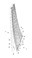
図1(a)には、航空機の主翼1の下面外板3が示されている。下面外板3は、繊維強化プラスチック(FRP:Fiber Reinforced Plastics)製の複合材構造体と、金属製構造体とで形成されている。同図に示した破線は、フラップやスラット等を含む主翼1の外形線を示している。
Hereinafter, an embodiment of the present invention will be described with reference to FIGS. 1 to 3.
FIG. 1 (a) shows a
下面外板3は、図2及び図3に示したように、下面外板3の幅方向両端から立設する側面外板となるフロントスパー20及びリアスパー22と、これらフロントスパー20及びリアスパー22の上端同士を接続する上面外板24と共に箱形のトルクボックスを形成しており、主翼1の荷重を負担する。
As shown in FIGS. 2 and 3, the lower surface
下面外板3は、主翼1の前縁側に位置する前方部(隣接構造部材)3aと、前方部3aに接続された中央部3bと、中央部3bに接続され、主翼1の後縁側に位置する後方部(隣接構造部材)3cとの3つの部分から構成されている。前方部3a、中央部3b及び後方部3cは、主翼1の長手方向に延在する分割面4にて、それぞれ、ファスナによって、又は、接着によって結合されている。この結合方法の具体例については、後述するが、ファスナ結合か接着結合かは適宜選択すれば良く、ファスナ結合は艤装が容易となる利点があり、接着結合は軽量化が可能となる利点がある。
The lower surface
図2及び図3に示されているように、主翼1の長手方向には、複数のストリンガ26が設けられている。ストリンガ26は、FRP(繊維強化プラスチック)製の複合材とされている。各ストリンガ26は、下面外板3及び上面外板24の内表面に対して固定されており、主翼1の長手方向の荷重を主として負担する。
また、ボックス構造とされた主翼1の内部には、その内部空間を長手方向において複数に分割するようにリブ28が設けられている。リブ28は、主翼1の幅方向(長手方向に直交する方向)にわたって延在した板状とされており、長手方向に所定間隔を有して複数配置されている。図3に示すように、各リブ28の前後の端部は、それぞれ、フロントスパー20及びリアスパー22に対してボルト・ナット等の所定のファスナ30によって固定されている。
As shown in FIGS. 2 and 3, a plurality of
A
下面外板3の前方部3aは、炭素繊維強化プラスチック(CFRP:Carbon Fiber Reinforced Plastics)が主体とされた複合材となっている。炭素繊維の配向の比率は、航空機の構造体として用いられる通常程度とされており、例えば、主翼1の延在方向(長手方向)を0°とした場合、(0°,+45°,−45°,90°)=(30%,30%,30%,10%)となるように、各繊維方向を有する複数のシートが積層されて構成されている。前方部3aに用いられる複合材の積層数は、負担する強度によって決定される。
The
下面外板3の後方部3cは、前方部3aと同様に、炭素繊維強化プラスチック(CFRP)が主体とされた複合材となっている。炭素繊維の配向の比率は、前方部3aと同様に、航空機の構造体として用いられる通常程度とされており、例えば、主翼1の延在方向を0°とした場合、(0°,+45°,−45°,90°)=(30%,30%,30%,10%)となるように、各繊維方向を有する複数のシートが積層されて構成されている。後方部3cに用いられる複合材の積層数は、負担する強度によって決定される。
The
下面外板3の中央部3bは、チタン合金やアルミ合金等の金属製とされている。中央部3bに、主翼1内に設けられた燃料タンクの点検時や組立時等に用いるためのアクセスホール(孔)5が、主翼1の延在方向に沿って所定間隔ごとに複数形成されている。このように、中央部3bは、孔付き構造部材となっている。なお、上述した前方部3a及び後方部3cには、アクセスホール5が形成されていない。
中央部3bは、図1(b)に示されているように、前方部3a及び後方部3cに隣接する定厚領域3b−1は前方部3a及び後方部3cとほぼ同じ厚さとされており、この定厚領域3b−1は、アクセスホール5の周縁部に設けられた周縁領域3b−2を取り囲むように設けられている。周縁領域3b−2は、定厚領域3b−1よりも増厚されている。この増厚された周縁領域3b−2が、アクセスホール5の周縁部に生じる応力集中に対する補強となっている。また、周縁領域3b−2と隣接領域3b−1とは、フィレットR処理部3b−3によって接続されている。つまり、中央部3bは金属製とされているので、強化繊維プラスチックを用いた場合(図6(b)参照)のようにテーパ部分104bを設けずに、フィレットR処理部3b−3によって周縁領域3b−2と隣接領域3b−1とを接続することができる。したがって、図1(b)に比較としてテーパ部分104bを示したように、テーパ部分104bを設けた場合に比べて余肉を省略することができ、軽量化を図ることができる。
The
As shown in FIG. 1B, the
次に、図4を用いて、下面外板3の中央部3bと、前方部3a及び後方部3cとの結合方法について説明する。
Next, a method of connecting the
図4(a)に示すように、ストリンガ26と、下面外板3(中央部3c,前方部3a及び後方部3c)との固定は、一点鎖線で示した位置に、ボルト・ナット等から構成されるファスナ40によって行われる。
また、図4(b)に示すように、ストリンガ26と前方部3a(又は後方部3c)との間の接着部42にて接着させ、ストリンガ26と中央部3bとをファスナ40によって固定する方法としてもよい。なお、図4(b)に示した方法と逆の方法、すなわち、ストリンガ26と前方部3a(又は後方部3c)とをファスナ40によって固定し、ストリンガ26と中央部3bとの間を接着部42にて接着させてもよい。ストリンガ26と前方部3a(又は後方部3c)の結合は前記接着のみの結合としてもよいが、接着強度又は接着強度の信頼性が十分でない場合はファスナ40を併用してもよい。
また、図4(c)に示すように、ストリンガ26と前方部3a(又は後方部3c)との間、及び、ストリンガ26と中央部3bとの間に接着部42を介在させて接着させた後に、ファスナ40によって固定する方法としてもよい。
また、図4(d)に示すように、ファスナを用いずに接着部42における接着のみによって固定する方法としてもよい。
As shown in FIG. 4 (a), the
Further, as shown in FIG. 4B, a method of bonding the
Moreover, as shown in FIG.4 (c), it adhered by interposing the
Moreover, as shown in FIG.4 (d), it is good also as a method of fixing only by adhesion | attachment in the
なお、接着としては、ストリンガ26と、前方部3a(又は後方部3c)との両者をそれぞれ硬化させた後に、接着剤を用いて接着する方法(キュア後接着法)の他、硬化後のストリンガ26と、硬化前の前方部3a(又は後方部3c)又は、硬化前のストリンガ26と、硬化後の前方部3a(又は後方部3c)との間に接着剤を介挿した後に、温度及び/又は圧力を加えて一体的に硬化させるコボンド(co-bond)法や、硬化前のストリンガ26と硬化前の前方部3a(又は後方部3c)との間に接着剤を介挿した後に、温度及び/又は圧力を加えて一体的に硬化させるコキュア(co-cure)法等が用いられる。
In addition, as the bonding, the
また、図4(e)に示すように、分割面4を板厚方向に対して傾斜するように設け、接着部42にて接着させることとしても良い。このように傾斜面とされた分割面4とすれば、中央部3bと前方部3a(又は後方部3c)とが重なり合って接触する面積が大きくなるので、より安定的に結合することができる。
Further, as shown in FIG. 4E, the dividing
次に、上記構成の主翼1を用いた際の作用効果について説明する。
飛行時、主翼1には、その先端が上向きに変位するように荷重が加わる。したがって、主翼1の下面外板3には、その延在方向(0°方向)に引張り荷重が加わる。0°方向の引張り荷重は、中央部3bに形成されたアクセスホール5の周縁部に応力集中を発生させる。本実施形態では、中央部3bを金属製としたので、繊維強化プラスチック製の複合材とした場合のように剥離防止のためのテーパ部104b(図6(b)参照)を孔周縁部に設ける必要がない。したがって、テーパ部を形成するための余肉を省略することができるので、軽量化された中央部3bを実現することができる。
Next, the effect at the time of using the main wing |
During flight, a load is applied to the
なお、本実施形態は主翼1の下面外板3への適用について説明したが、本発明はこれに限定されず、孔を有する複合材構造体であれば広く適用することができる。
例えば、下面外板3とともにトルクボックスを構成する上面外板に、下面外板3と同様の構成を適用しても良い。
In addition, although this embodiment demonstrated the application to the lower surface
For example, the same configuration as that of the lower surface
また、図5に示すように、窓材が設置される窓用孔11が形成された航空機胴体10の中央部12に、上記実施形態の金属製の中央部3bを適用し、隣接する他の部材13に上記実施形態の前方部3a及び後方部3cと同様の材料を適用しても良い。
Further, as shown in FIG. 5, the metal
上記実施形態では、主として炭素繊維強化プラスチック(CFRP)を主として用いることとしたが、本発明はこれに限定されず、例えばガラス繊維強化プラスチック(GFRP:Glass Fiber Reinforced Plastic)やアラミド繊維強化プラスチック(AFRP:Aramid Fiber Reinforced Plastic)を用いても良い。 Above Symbol embodiment, it is assumed that mainly used mainly carbon fiber reinforced plastics (CFRP), the present invention is not limited thereto, for example, glass fiber reinforced plastic (GFRP: Glass Fiber Reinforced Plastic) or aramid fiber reinforced plastic ( AFRP (Aramid Fiber Reinforced Plastic) may be used.
1 主翼
3 下面外板(複合材構造体)
3a 前方部(隣接構造部材)
3b 中央部(孔付き構造部材)
3c 後方部(隣接構造部材)
5 アクセスホール(孔)
1
3a Front part (adjacent structural member)
3b Center part (structural member with hole)
3c Rear part (adjacent structural member)
5 Access hole (hole)
Claims (5)
前記一方向に延在するとともに前記孔付き構造部材の側部でかつ前記孔を避けた位置に接続された繊維強化プラスチック製の複合材とされた隣接構造部材と、
を備え、
前記孔付き構造部材は、
定厚領域と、
該定厚領域よりも増厚され、前記孔の周縁部を補強する周縁領域と、
を備えていることを特徴とする航空機用複合材構造体。 A perforated structural member made of metal and extending in one direction and having holes formed therein;
An adjacent structural member that is a composite material made of fiber reinforced plastic that extends in the one direction and is connected to a side portion of the structural member with a hole and avoiding the hole ;
With
The perforated structural member is
Constant thickness region,
A peripheral region that is thicker than the constant thickness region and reinforces the peripheral portion of the hole;
An aircraft composite structure characterized by comprising:
前記一方向に延在するとともに前記孔付き構造部材の側部に接続された繊維強化プラスチック製の複合材とされた隣接構造部材と、
を備え、
前記孔付き構造部材は、
定厚領域と、
該定厚領域よりも増厚され、前記孔の周縁部を補強する周縁領域と、
を備え、
航空機の主翼の下面外板が、該主翼の長手方向に延在する複数の部材で構成され、
これら部材のうち、前記下面外板に形成された前記孔としてアクセスホールを有する部材が前記孔付き構造部材とされ、他の部材が前記隣接構造部材とされていることを特徴とする航空機用複合材構造体。 A perforated structural member made of metal and extending in one direction and having holes formed therein;
An adjacent structural member that is a composite material made of fiber-reinforced plastic that extends in the one direction and is connected to a side portion of the structural member with holes,
With
The perforated structural member is
Constant thickness region,
A peripheral region that is thicker than the constant thickness region and reinforces the peripheral portion of the hole;
With
The lower skin of the main wing of the aircraft is composed of a plurality of members extending in the longitudinal direction of the main wing,
Of these members, members having the access hole as the hole formed in the lower outer plate is said apertured structural member, aviation other members you characterized in that there is a said adjacent structural member Composite material structure for machine.
前記一方向に延在するとともに前記孔付き構造部材の側部に接続された繊維強化プラスチック製の複合材とされた隣接構造部材と、
を備え、
前記孔付き構造部材は、
定厚領域と、
該定厚領域よりも増厚され、前記孔の周縁部を補強する周縁領域と、
を備え、
航空機の胴体の外板が、該胴体の長手方向に延在する複数の部材で構成され、
これら部材のうち、前記外板に形成された前記孔として窓用孔を有する部材が前記孔付き構造部材とされ、他の部材が前記隣接構造部材とされていることを特徴とする航空機用複合材構造体。 A perforated structural member made of metal and extending in one direction and having holes formed therein;
An adjacent structural member that is a composite material made of fiber-reinforced plastic that extends in the one direction and is connected to a side portion of the structural member with holes,
With
The perforated structural member is
Constant thickness region,
A peripheral region that is thicker than the constant thickness region and reinforces the peripheral portion of the hole;
With
The outer shell of the aircraft fuselage is composed of a plurality of members extending in the longitudinal direction of the fuselage,
Of these members, members having a window hole as the hole formed in the outer plate is said apertured structural member, aviation other members you characterized in that there is a said adjacent structural member Composite material structure for machine.
Priority Applications (5)
| Application Number | Priority Date | Filing Date | Title |
|---|---|---|---|
| JP2011023154A JP5808111B2 (en) | 2011-02-04 | 2011-02-04 | Composite structure for aircraft, aircraft main wing and aircraft fuselage provided with the same |
| EP12742098.2A EP2671794B1 (en) | 2011-02-04 | 2012-01-26 | Composite material structure, and aircraft wing and fuselage provided therewith |
| PCT/JP2012/051699 WO2012105415A1 (en) | 2011-02-04 | 2012-01-26 | Composite material structure, and aircraft wing and fuselage provided therewith |
| US13/881,590 US9751608B2 (en) | 2011-02-04 | 2012-01-26 | Composite material structure, and aircraft wing and aircraft fuselage provided therewith |
| CN201280003462.8A CN103180207B (en) | 2011-02-04 | 2012-01-26 | Composite material structure body, the aerocraft main wing possessing this composite material structure body and aircraft fuselage |
Applications Claiming Priority (1)
| Application Number | Priority Date | Filing Date | Title |
|---|---|---|---|
| JP2011023154A JP5808111B2 (en) | 2011-02-04 | 2011-02-04 | Composite structure for aircraft, aircraft main wing and aircraft fuselage provided with the same |
Publications (3)
| Publication Number | Publication Date |
|---|---|
| JP2012162147A JP2012162147A (en) | 2012-08-30 |
| JP2012162147A5 JP2012162147A5 (en) | 2014-03-20 |
| JP5808111B2 true JP5808111B2 (en) | 2015-11-10 |
Family
ID=46602632
Family Applications (1)
| Application Number | Title | Priority Date | Filing Date |
|---|---|---|---|
| JP2011023154A Expired - Fee Related JP5808111B2 (en) | 2011-02-04 | 2011-02-04 | Composite structure for aircraft, aircraft main wing and aircraft fuselage provided with the same |
Country Status (5)
| Country | Link |
|---|---|
| US (1) | US9751608B2 (en) |
| EP (1) | EP2671794B1 (en) |
| JP (1) | JP5808111B2 (en) |
| CN (1) | CN103180207B (en) |
| WO (1) | WO2012105415A1 (en) |
Cited By (1)
| Publication number | Priority date | Publication date | Assignee | Title |
|---|---|---|---|---|
| US11040512B2 (en) | 2017-11-08 | 2021-06-22 | Northrop Grumman Systems Corporation | Composite structures, forming apparatuses and related systems and methods |
Families Citing this family (14)
| Publication number | Priority date | Publication date | Assignee | Title |
|---|---|---|---|---|
| JP6004669B2 (en) | 2012-02-29 | 2016-10-12 | 三菱重工業株式会社 | Composite structure, aircraft wing and aircraft fuselage provided with the same, and method for manufacturing composite structure |
| US20150203187A1 (en) * | 2013-04-02 | 2015-07-23 | The Boeing Company | Continuously Curved Spar and Method of Manufacturing |
| US9580164B2 (en) * | 2013-07-10 | 2017-02-28 | The Boeing Company | Apparatus and methods for joining aircraft composite structures |
| JP6204093B2 (en) * | 2013-07-12 | 2017-09-27 | 三菱重工業株式会社 | Method for manufacturing reinforcing structure |
| JP6204092B2 (en) * | 2013-07-12 | 2017-09-27 | 三菱重工業株式会社 | Method for manufacturing reinforcing structure |
| JP6309324B2 (en) | 2014-03-28 | 2018-04-11 | 三菱重工業株式会社 | Composite structure, aircraft wing and aircraft fuselage provided with the same, and method for manufacturing composite structure |
| US9499275B2 (en) * | 2014-10-16 | 2016-11-22 | Rohr, Inc. | Stress-relieving joint between materials with differing coefficients of thermal expansion |
| US9849967B2 (en) * | 2015-04-01 | 2017-12-26 | The Boeing Company | Composite rib for an aircraft |
| US10040536B2 (en) * | 2015-09-17 | 2018-08-07 | The Boeing Company | Wing structure, stringer structure, and related apparatus and methods of assembly |
| CN105253291A (en) * | 2015-10-14 | 2016-01-20 | 哈尔滨飞机工业集团有限责任公司 | Aerofoil integrated machine stiffened wall plate with comb-shaped connector and application |
| CN110290919A (en) * | 2017-02-22 | 2019-09-27 | 三菱重工业株式会社 | The manufacturing method of composite material and composite material |
| CN107244409B (en) * | 2017-05-31 | 2019-08-09 | 彩虹无人机科技有限公司 | A kind of composite wing integral tank structure |
| US11667371B2 (en) * | 2020-04-03 | 2023-06-06 | The Boeing Company | Composite materials having reinforced access openings |
| US11780185B2 (en) | 2021-03-05 | 2023-10-10 | GM Global Technology Operations LLC | Reinforced composite assemblies and methods of manufacturing the same |
Family Cites Families (24)
| Publication number | Priority date | Publication date | Assignee | Title |
|---|---|---|---|---|
| US4033243A (en) * | 1976-01-30 | 1977-07-05 | Textron, Inc. | Container fastener system |
| DE3113079C2 (en) | 1981-04-01 | 1985-11-21 | Messerschmitt-Bölkow-Blohm GmbH, 8000 München | Large aerodynamic wing and process for its manufacture |
| US4749155A (en) | 1985-09-30 | 1988-06-07 | The Boeing Company | Method of making wing box cover panel |
| US4741943A (en) | 1985-12-30 | 1988-05-03 | The Boeing Company | Aerodynamic structures of composite construction |
| US5079055A (en) * | 1989-09-21 | 1992-01-07 | Doyle Brian P | Reinforcement for laminate synthetic materials |
| FR2745589B1 (en) * | 1996-02-29 | 1998-04-30 | Snecma | HIGH STRENGTH-TO-MASS HYBRID PART AND METHOD FOR PRODUCING THE SAME |
| US6220651B1 (en) | 1996-09-12 | 2001-04-24 | Wabash Technology Corporation | Composite joint configuration |
| US5860693A (en) | 1996-09-12 | 1999-01-19 | Wabash National Corporation | Composite joint configuration |
| JP2000006893A (en) | 1998-06-23 | 2000-01-11 | Fuji Heavy Ind Ltd | Composite material wing structure |
| JP2000135527A (en) * | 1998-10-28 | 2000-05-16 | Tachi S Co Ltd | Reinforced penetration hole forming method of steel plate and, stepped shaft fastening structure of steel plate |
| JP4187878B2 (en) | 1999-07-19 | 2008-11-26 | 富士重工業株式会社 | Aircraft composite wing and method for manufacturing the same |
| GB9926579D0 (en) | 1999-11-11 | 2000-01-12 | British Aerospace | Reinforcement of a laminated member for an aircraft |
| JP4545339B2 (en) * | 2001-04-05 | 2010-09-15 | 富士重工業株式会社 | COMPOSITE WING AND MANUFACTURING METHOD THEREOF |
| JP4574086B2 (en) | 2001-09-03 | 2010-11-04 | 富士重工業株式会社 | Method for manufacturing composite wing and composite wing |
| JP2004155157A (en) * | 2002-11-08 | 2004-06-03 | Mitsubishi Heavy Ind Ltd | Composite material joint |
| EP1419961A1 (en) * | 2002-11-15 | 2004-05-19 | IPA N.V.-Composites | Hollow crank arm for bicycle |
| US7300693B2 (en) | 2003-09-04 | 2007-11-27 | The Boeing Company | Resin infused transparent skin panel and method of making same |
| US8464893B2 (en) * | 2005-06-06 | 2013-06-18 | Toyota Jidosha Kabushiki Kaisha | Pressure container and method of producing the same |
| NL2000232C2 (en) * | 2006-09-12 | 2008-03-13 | Gtm Consulting B V | Skin panel for an aircraft fuselage. |
| FR2906785B1 (en) | 2006-10-10 | 2009-12-04 | Airbus France | AIRCRAFT FUSELAGE MADE FROM LONGITUDINAL PANELS AND METHOD FOR PRODUCING SUCH A FUSELAGE |
| EP1932757B1 (en) * | 2006-12-15 | 2016-10-26 | Airbus Deutschland GmbH | Bonded aluminium window frame on fibre metal laminate fuselage skin |
| FR2921898B1 (en) | 2007-10-08 | 2009-12-11 | Airbus France | FUSELAGE STRUCTURE FOR AIRCRAFT FUSELAGE IN COMPOSITE MATERIAL AND AIRCRAFT EQUIPPED WITH SUCH A FUSELAGE STRUCTURE |
| JP2010038245A (en) * | 2008-08-05 | 2010-02-18 | Tsubakimoto Chain Co | Silent chain |
| JP5237170B2 (en) * | 2009-03-30 | 2013-07-17 | 三菱重工業株式会社 | COMPOSITE TANK, WING, AND METHOD FOR PRODUCING COMPOSITE TANK |
-
2011
- 2011-02-04 JP JP2011023154A patent/JP5808111B2/en not_active Expired - Fee Related
-
2012
- 2012-01-26 US US13/881,590 patent/US9751608B2/en active Active
- 2012-01-26 CN CN201280003462.8A patent/CN103180207B/en not_active Expired - Fee Related
- 2012-01-26 EP EP12742098.2A patent/EP2671794B1/en active Active
- 2012-01-26 WO PCT/JP2012/051699 patent/WO2012105415A1/en active Application Filing
Cited By (1)
| Publication number | Priority date | Publication date | Assignee | Title |
|---|---|---|---|---|
| US11040512B2 (en) | 2017-11-08 | 2021-06-22 | Northrop Grumman Systems Corporation | Composite structures, forming apparatuses and related systems and methods |
Also Published As
| Publication number | Publication date |
|---|---|
| CN103180207A (en) | 2013-06-26 |
| WO2012105415A1 (en) | 2012-08-09 |
| CN103180207B (en) | 2015-10-14 |
| EP2671794A1 (en) | 2013-12-11 |
| US9751608B2 (en) | 2017-09-05 |
| US20130236692A1 (en) | 2013-09-12 |
| JP2012162147A (en) | 2012-08-30 |
| EP2671794B1 (en) | 2019-07-03 |
| EP2671794A4 (en) | 2018-01-10 |
Similar Documents
| Publication | Publication Date | Title |
|---|---|---|
| JP5808111B2 (en) | Composite structure for aircraft, aircraft main wing and aircraft fuselage provided with the same | |
| JP5308533B2 (en) | Composite structure, aircraft main wing and aircraft fuselage provided with the same | |
| JP2012162147A5 (en) | ||
| JP5808112B2 (en) | Composite structure and aircraft main wing provided with the same | |
| JP6628955B2 (en) | Vertically integrated stringer | |
| EP2440392B1 (en) | Method of producing an aircraft structure comprising a nano-reinforced radius filler | |
| KR102024396B1 (en) | Lower joints between outboard wing boxes and center wing sections of aircraft wing assemblies | |
| CN103963956A (en) | Box structure for carrying load and method of making the same | |
| EP2835310B1 (en) | Aircraft side of body joint | |
| JP6930876B2 (en) | Aircraft wing and aircraft including the aircraft wing | |
| JP6309324B2 (en) | Composite structure, aircraft wing and aircraft fuselage provided with the same, and method for manufacturing composite structure | |
| JP5654055B2 (en) | Composite structure, aircraft main wing and aircraft fuselage provided with the same | |
| KR20130139929A (en) | Stiffener run-out | |
| US8679616B2 (en) | Skew-angle radius filler | |
| US11020912B2 (en) | Joint structure | |
| US20130270392A1 (en) | Interface arrangement for aircraft lifting surface | |
| US8291671B2 (en) | Joint arrangement for composite-material structural members | |
| US10364017B2 (en) | Structural component |
Legal Events
| Date | Code | Title | Description |
|---|---|---|---|
| A521 | Request for written amendment filed |
Free format text: JAPANESE INTERMEDIATE CODE: A523 Effective date: 20140203 |
|
| A621 | Written request for application examination |
Free format text: JAPANESE INTERMEDIATE CODE: A621 Effective date: 20140203 |
|
| A131 | Notification of reasons for refusal |
Free format text: JAPANESE INTERMEDIATE CODE: A131 Effective date: 20150106 |
|
| A521 | Request for written amendment filed |
Free format text: JAPANESE INTERMEDIATE CODE: A523 Effective date: 20150309 |
|
| TRDD | Decision of grant or rejection written | ||
| A01 | Written decision to grant a patent or to grant a registration (utility model) |
Free format text: JAPANESE INTERMEDIATE CODE: A01 Effective date: 20150811 |
|
| A61 | First payment of annual fees (during grant procedure) |
Free format text: JAPANESE INTERMEDIATE CODE: A61 Effective date: 20150908 |
|
| R151 | Written notification of patent or utility model registration |
Ref document number: 5808111 Country of ref document: JP Free format text: JAPANESE INTERMEDIATE CODE: R151 |
|
| LAPS | Cancellation because of no payment of annual fees |