JP5806387B2 - Method for driving liquid ejection head and recording apparatus - Google Patents
Method for driving liquid ejection head and recording apparatus Download PDFInfo
- Publication number
- JP5806387B2 JP5806387B2 JP2014507587A JP2014507587A JP5806387B2 JP 5806387 B2 JP5806387 B2 JP 5806387B2 JP 2014507587 A JP2014507587 A JP 2014507587A JP 2014507587 A JP2014507587 A JP 2014507587A JP 5806387 B2 JP5806387 B2 JP 5806387B2
- Authority
- JP
- Japan
- Prior art keywords
- sent
- pressurizing
- pressurizing chamber
- pulse
- volume
- Prior art date
- Legal status (The legal status is an assumption and is not a legal conclusion. Google has not performed a legal analysis and makes no representation as to the accuracy of the status listed.)
- Active
Links
Images
Classifications
-
- B—PERFORMING OPERATIONS; TRANSPORTING
- B41—PRINTING; LINING MACHINES; TYPEWRITERS; STAMPS
- B41J—TYPEWRITERS; SELECTIVE PRINTING MECHANISMS, i.e. MECHANISMS PRINTING OTHERWISE THAN FROM A FORME; CORRECTION OF TYPOGRAPHICAL ERRORS
- B41J2/00—Typewriters or selective printing mechanisms characterised by the printing or marking process for which they are designed
- B41J2/005—Typewriters or selective printing mechanisms characterised by the printing or marking process for which they are designed characterised by bringing liquid or particles selectively into contact with a printing material
- B41J2/01—Ink jet
- B41J2/015—Ink jet characterised by the jet generation process
- B41J2/04—Ink jet characterised by the jet generation process generating single droplets or particles on demand
- B41J2/045—Ink jet characterised by the jet generation process generating single droplets or particles on demand by pressure, e.g. electromechanical transducers
- B41J2/04501—Control methods or devices therefor, e.g. driver circuits, control circuits
- B41J2/04541—Specific driving circuit
-
- B—PERFORMING OPERATIONS; TRANSPORTING
- B41—PRINTING; LINING MACHINES; TYPEWRITERS; STAMPS
- B41J—TYPEWRITERS; SELECTIVE PRINTING MECHANISMS, i.e. MECHANISMS PRINTING OTHERWISE THAN FROM A FORME; CORRECTION OF TYPOGRAPHICAL ERRORS
- B41J2/00—Typewriters or selective printing mechanisms characterised by the printing or marking process for which they are designed
- B41J2/005—Typewriters or selective printing mechanisms characterised by the printing or marking process for which they are designed characterised by bringing liquid or particles selectively into contact with a printing material
- B41J2/01—Ink jet
- B41J2/015—Ink jet characterised by the jet generation process
- B41J2/04—Ink jet characterised by the jet generation process generating single droplets or particles on demand
- B41J2/045—Ink jet characterised by the jet generation process generating single droplets or particles on demand by pressure, e.g. electromechanical transducers
- B41J2/04501—Control methods or devices therefor, e.g. driver circuits, control circuits
- B41J2/04525—Control methods or devices therefor, e.g. driver circuits, control circuits reducing occurrence of cross talk
-
- B—PERFORMING OPERATIONS; TRANSPORTING
- B41—PRINTING; LINING MACHINES; TYPEWRITERS; STAMPS
- B41J—TYPEWRITERS; SELECTIVE PRINTING MECHANISMS, i.e. MECHANISMS PRINTING OTHERWISE THAN FROM A FORME; CORRECTION OF TYPOGRAPHICAL ERRORS
- B41J2/00—Typewriters or selective printing mechanisms characterised by the printing or marking process for which they are designed
- B41J2/005—Typewriters or selective printing mechanisms characterised by the printing or marking process for which they are designed characterised by bringing liquid or particles selectively into contact with a printing material
- B41J2/01—Ink jet
- B41J2/015—Ink jet characterised by the jet generation process
- B41J2/04—Ink jet characterised by the jet generation process generating single droplets or particles on demand
- B41J2/045—Ink jet characterised by the jet generation process generating single droplets or particles on demand by pressure, e.g. electromechanical transducers
- B41J2/04501—Control methods or devices therefor, e.g. driver circuits, control circuits
- B41J2/04581—Control methods or devices therefor, e.g. driver circuits, control circuits controlling heads based on piezoelectric elements
-
- B—PERFORMING OPERATIONS; TRANSPORTING
- B41—PRINTING; LINING MACHINES; TYPEWRITERS; STAMPS
- B41J—TYPEWRITERS; SELECTIVE PRINTING MECHANISMS, i.e. MECHANISMS PRINTING OTHERWISE THAN FROM A FORME; CORRECTION OF TYPOGRAPHICAL ERRORS
- B41J2/00—Typewriters or selective printing mechanisms characterised by the printing or marking process for which they are designed
- B41J2/005—Typewriters or selective printing mechanisms characterised by the printing or marking process for which they are designed characterised by bringing liquid or particles selectively into contact with a printing material
- B41J2/01—Ink jet
- B41J2/015—Ink jet characterised by the jet generation process
- B41J2/04—Ink jet characterised by the jet generation process generating single droplets or particles on demand
- B41J2/045—Ink jet characterised by the jet generation process generating single droplets or particles on demand by pressure, e.g. electromechanical transducers
- B41J2/04501—Control methods or devices therefor, e.g. driver circuits, control circuits
- B41J2/04596—Non-ejecting pulses
-
- B—PERFORMING OPERATIONS; TRANSPORTING
- B41—PRINTING; LINING MACHINES; TYPEWRITERS; STAMPS
- B41J—TYPEWRITERS; SELECTIVE PRINTING MECHANISMS, i.e. MECHANISMS PRINTING OTHERWISE THAN FROM A FORME; CORRECTION OF TYPOGRAPHICAL ERRORS
- B41J2/00—Typewriters or selective printing mechanisms characterised by the printing or marking process for which they are designed
- B41J2/005—Typewriters or selective printing mechanisms characterised by the printing or marking process for which they are designed characterised by bringing liquid or particles selectively into contact with a printing material
- B41J2/01—Ink jet
- B41J2/135—Nozzles
- B41J2/14—Structure thereof only for on-demand ink jet heads
- B41J2/14201—Structure of print heads with piezoelectric elements
- B41J2/14233—Structure of print heads with piezoelectric elements of film type, deformed by bending and disposed on a diaphragm
-
- B—PERFORMING OPERATIONS; TRANSPORTING
- B41—PRINTING; LINING MACHINES; TYPEWRITERS; STAMPS
- B41J—TYPEWRITERS; SELECTIVE PRINTING MECHANISMS, i.e. MECHANISMS PRINTING OTHERWISE THAN FROM A FORME; CORRECTION OF TYPOGRAPHICAL ERRORS
- B41J2/00—Typewriters or selective printing mechanisms characterised by the printing or marking process for which they are designed
- B41J2/005—Typewriters or selective printing mechanisms characterised by the printing or marking process for which they are designed characterised by bringing liquid or particles selectively into contact with a printing material
- B41J2/01—Ink jet
- B41J2/135—Nozzles
- B41J2/145—Arrangement thereof
- B41J2/155—Arrangement thereof for line printing
-
- B—PERFORMING OPERATIONS; TRANSPORTING
- B41—PRINTING; LINING MACHINES; TYPEWRITERS; STAMPS
- B41J—TYPEWRITERS; SELECTIVE PRINTING MECHANISMS, i.e. MECHANISMS PRINTING OTHERWISE THAN FROM A FORME; CORRECTION OF TYPOGRAPHICAL ERRORS
- B41J2/00—Typewriters or selective printing mechanisms characterised by the printing or marking process for which they are designed
- B41J2/005—Typewriters or selective printing mechanisms characterised by the printing or marking process for which they are designed characterised by bringing liquid or particles selectively into contact with a printing material
- B41J2/01—Ink jet
- B41J2/135—Nozzles
- B41J2/14—Structure thereof only for on-demand ink jet heads
- B41J2002/14459—Matrix arrangement of the pressure chambers
-
- B—PERFORMING OPERATIONS; TRANSPORTING
- B41—PRINTING; LINING MACHINES; TYPEWRITERS; STAMPS
- B41J—TYPEWRITERS; SELECTIVE PRINTING MECHANISMS, i.e. MECHANISMS PRINTING OTHERWISE THAN FROM A FORME; CORRECTION OF TYPOGRAPHICAL ERRORS
- B41J2202/00—Embodiments of or processes related to ink-jet or thermal heads
- B41J2202/01—Embodiments of or processes related to ink-jet heads
- B41J2202/20—Modules
Landscapes
- Particle Formation And Scattering Control In Inkjet Printers (AREA)
- Ink Jet (AREA)
Description
本発明は、液滴を吐出させる液体吐出ヘッドの駆動方法および記録装置に関するものである。 The present invention relates to a driving method of a liquid discharge head that discharges liquid droplets and a recording apparatus.
近年、インクジェットプリンタやインクジェットプロッタなどの、インクジェット記録方式を利用した印刷装置が、一般消費者向けのプリンタだけでなく、例えば電子回路の形成や液晶ディスプレイ用のカラーフィルタの製造、有機ELディスプレイの製造といった工業用途にも広く利用されている。 In recent years, printing apparatuses using inkjet recording methods such as inkjet printers and inkjet plotters are not only printers for general consumers, but also, for example, formation of electronic circuits, manufacture of color filters for liquid crystal displays, manufacture of organic EL displays It is also widely used for industrial applications.
このようなインクジェット方式の印刷装置には、液体を吐出させるための液体吐出ヘッドが印刷ヘッドとして搭載されている。この種の印刷ヘッドには、インクが充填されたインク流路内に加圧手段としてのヒータを備え、ヒータによりインクを加熱、沸騰させ、インク流路内に発生する気泡によってインクを加圧し、インク吐出孔より、液滴として吐出させるサーマルヘッド方式と、インクが充填されるインク流路の一部の壁を変位素子によって屈曲変位させ、機械的にインク流路内のインクを加圧し、インク吐出孔より液滴として吐出させる圧電方式が一般的に知られている。 In such an ink jet printing apparatus, a liquid discharge head for discharging liquid is mounted as a print head. This type of print head includes a heater as a pressurizing unit in an ink flow path filled with ink, heats and boiles the ink with the heater, pressurizes the ink with bubbles generated in the ink flow path, A thermal head system that ejects ink as droplets from the ink ejection holes, and a part of the wall of the ink channel filled with ink is bent and displaced by a displacement element, and the ink in the ink channel is mechanically pressurized, and the ink A piezoelectric method for discharging liquid droplets from discharge holes is generally known.
また、このような液体吐出ヘッドには、記録媒体の搬送方向(副走査方向)と直交する方向(主走査方向)に液体吐出ヘッドを移動させつつ記録を行なうシリアル式、および記録媒体より主走査方向に長い液体吐出ヘッドを固定した状態で、副走査方向に搬送されてくる記録媒体に記録を行なうライン式がある。ライン式は、シリアル式のように液体吐出ヘッドを移動させる必要がないので、高速記録が可能であるという利点を有する。 In addition, in such a liquid discharge head, a serial type that performs recording while moving the liquid discharge head in a direction (main scanning direction) orthogonal to the conveyance direction (sub-scanning direction) of the recording medium, and main scanning from the recording medium There is a line type in which recording is performed on a recording medium conveyed in the sub-scanning direction with a liquid discharge head that is long in the direction fixed. The line type has the advantage that high-speed recording is possible because there is no need to move the liquid discharge head as in the serial type.
シリアル式、ライン式のいずれの方式の液体吐出ヘッドであっても、液滴を高い密度で印刷するには、液体吐出ヘッドに形成されている、液滴を吐出する吐出孔の密度を高くする必要がある。 In order to print droplets at a high density in any of the serial type and line type liquid discharge heads, the density of the discharge holes for discharging the droplets formed in the liquid discharge head is increased. There is a need.
そこで液体吐出ヘッドを、マニホールドおよびマニホールドから複数の加圧室をそれぞれ介して繋がる吐出孔を有した流路部材と、前記複数の加圧室を覆うように設けられた、複数の個別電極と複数の個別電極に対向している共通電極とそれらに挟まれている圧電セラミック層とを含む複数の変位素子を有する圧電アクチュエータ基板とを積層して構成したものが知られている(例えば、特許文献1を参照。)。この液体吐出ヘッドでは、複数の吐出孔にそれぞれ繋がった加圧室がマトリックス状に配置され、それを覆うように設けられたアクチュエータユニットの変位素子を圧電体の変形により変位させることで、各吐出孔からインクを吐出させ、主走査方向に600dpiの解像度で印刷が可能とされている。 In view of this, the liquid discharge head includes a manifold and a flow path member having discharge holes connected to the manifold via a plurality of pressurization chambers, a plurality of individual electrodes and a plurality of individual electrodes provided so as to cover the plurality of pressurization chambers. There is known a structure in which a piezoelectric actuator substrate having a plurality of displacement elements including a common electrode facing each individual electrode and a piezoelectric ceramic layer sandwiched between them is laminated (for example, patent document) 1). In this liquid discharge head, the pressurizing chambers connected to the plurality of discharge holes are arranged in a matrix, and the displacement element of the actuator unit provided so as to cover it is displaced by deformation of the piezoelectric body, so that each discharge Ink is ejected from the holes and printing is possible in the main scanning direction at a resolution of 600 dpi.
しかしながら、特許文献1に記載の液体吐出ヘッドでは、加圧室が密集して設けられており、しかも複数の加圧室を覆うように圧電アクチュエータ基板が積層されているため、液体吐出素子間でクロストークが生じ、記録精度が十分でなくなる場合があった。
However, in the liquid discharge head described in
クロストークを抑制する方法としては、例えば、加圧室の中の液体を加圧する加圧部を駆動する駆動信号を遅延させて送ることが考えられる。また、液体を吐出する信号として、メインパルスとキャンセルパルスで構成された信号を送ることが考えられる。しかし、これらを同時に行なおうとすると、隣接する液体吐出素子に送られるメインパルスおよびキャンセルパルスが、遅延されることで複雑に重なって送られることになるため、吐出特性がばらつくおそれがあった。 As a method for suppressing the crosstalk, for example, it is conceivable to delay and send a drive signal for driving a pressurizing unit that pressurizes the liquid in the pressurizing chamber. It is also conceivable to send a signal composed of a main pulse and a cancel pulse as a signal for ejecting liquid. However, if these operations are performed simultaneously, the main pulse and the cancel pulse sent to the adjacent liquid discharge elements are sent in a complicated manner by being delayed, and there is a possibility that the discharge characteristics may vary.
したがって、本発明の目的は、駆動信号を遅延させて駆動する際に、液体吐出特性ばらつきを小さくできる液体吐出ヘッドの駆動方法および記録装置を提供することにある。 Accordingly, an object of the present invention is to provide a driving method of a liquid discharge head and a recording apparatus capable of reducing variations in liquid discharge characteristics when driving with a drive signal being delayed.
本発明の一つの液体吐出ヘッドの駆動方法は、複数の吐出孔および該複数の吐出孔にそれぞれ繋がっている複数の加圧室を有している流路部材と、前記複数の加圧室を覆うように前記流路部材に積層されており、前記複数の加圧室の中の液体をそれぞれ加圧する複数の加圧部を有している圧電アクチュエータ基板と、を備え、前記流路部材は、複数の前記加圧室が直線状に並んでいる複数の加圧室列を含み、該複数の加圧室列が行方向に隣り合って並んでいる液体吐出ヘッドの駆動方法であって、前記加圧部に送られる駆動信号は、当該加圧部に対応する前記加圧室の体積を増加させた後、当該加圧室の体積を減少させて液体を吐出させるメインパルスと、該メインパルスを1つあるいは複数送る前に送られる、当該加圧室の体積を前記メインパルスよりも短い時間増加させた後、当該加圧室の体積を減少させて液体を吐出させないプレパルスと、前記メインパルスを1つあるいは複数送った後に送られる、当該加圧室の体積を前記メインパルスよりも短い時間増加させた後、当該加圧室の体積を減少させて液体を吐出させないキャンセルパルスとを含んでおり、各々の前記加圧室列に対応する前記加圧部には同時に駆動信号が送られ始めるとともに、隣り合っている前記加圧室列間には遅延を与えて駆動信号が送られ、各々の前記加圧部に送られる駆動信号は、前記プレパルスの前記加圧室の体積を減少させる信号が、当該加圧室に対して前記行方向(行方向とその反対方向も含む)に隣り合っている前記加圧室に対応している前記加圧部に送られる前記メインパルスまたは前記キャンセルパルスが送られている間に送られるか、前記キャンセルパルスの前記加圧室の体積を増加させる信号が、当該加圧室に対して前記行方向に隣り合っている前記加圧室に対応する前記加圧部に送られる前記メインパルスまたは前記プレパルスが送られている間に送られるか、のうちの少なくとも一方であることを特徴とする。 One liquid ejection head driving method according to the present invention includes a plurality of ejection holes, a flow path member having a plurality of pressurization chambers connected to the plurality of ejection holes, and the plurality of pressurization chambers. A piezoelectric actuator substrate that is stacked on the flow path member so as to cover and has a plurality of pressurizing sections that pressurize the liquid in the plurality of pressurization chambers, respectively, A method of driving a liquid ejection head, comprising a plurality of pressurizing chamber rows in which the plurality of pressurizing chambers are arranged in a straight line, wherein the plurality of pressurizing chamber rows are arranged side by side in the row direction, The drive signal sent to the pressurizing unit includes a main pulse for increasing the volume of the pressurizing chamber corresponding to the pressurizing unit and then decreasing the volume of the pressurizing chamber to discharge liquid, and the main pulse The volume of the pressurization chamber sent before sending one or more pulses is the volume After increasing the time shorter than the pulse, the volume of the pressurizing chamber is decreased and the volume of the pressurizing chamber sent after sending one or more main pulses is reduced. And a cancel pulse that decreases the volume of the pressurizing chamber after a time shorter than the pulse and does not discharge the liquid, and simultaneously drives the pressurizing units corresponding to the pressurizing chamber rows. As the signal starts to be sent, a drive signal is sent with a delay between the adjacent pressurizing chamber rows, and the drive signal sent to each pressurizing unit is connected to the pressurizing chamber of the prepulse. A signal for reducing the volume is sent to the pressurizing unit corresponding to the pressurizing chamber adjacent to the pressurizing chamber in the row direction (including the row direction and the opposite direction). Pulse or said A signal that increases the volume of the pressurization chamber of the cancel pulse that is sent while a cancel pulse is being sent corresponds to the pressurization chamber that is adjacent to the pressurization chamber in the row direction. The main pulse or the pre-pulse sent to the pressurizing unit is sent while being sent, and is at least one of them.
また、本発明の他の液体吐出ヘッドの駆動方法は、複数の吐出孔および該複数の吐出孔にそれぞれ繋がっている複数の加圧室を有している流路部材と、前記複数の加圧室を覆うように前記流路部材に積層されており、前記複数の加圧室の中の液体をそれぞれ加圧する複数の加圧部を有している圧電アクチュエータ基板と、を備え、前記流路部材は、複数の前記加圧室が直線状に並んでいる複数の加圧室列を含み、該複数の加圧室列が行方向に隣り合って並んでいる液体吐出ヘッドの駆動方法であって、前記加圧部に送られる駆動信号は、当該加圧部に対応する前記加圧室の体積を増加させた後、当該加圧室の体積を減少させて液体を吐出させるメインパルスと、該メインパルス1つあるいは複数送った後に送られる、当該加圧室の体積を前記メインパルスよりも短い時間増加させた後、当該加圧室の体積を減少させて液体を吐出させないキャンセルパルスとを含んでおり、各々の前記加圧室列に対応する前記加圧部には同時に駆動信号が送られ始めるとともに、隣り合っている前記加圧室列間には遅延を与えて駆動信号が送られ、各々の前記加圧部に送られる駆動信号は、前記行方向に隣り合っている前記加圧室に対応する前記加圧部のうちの一方の前記加圧部に送られる、遅延が与えられていない駆動信号の前記キャンセルパルスが、他方の前記加圧部に送られる、遅延が与えられている駆動信号の前記メインパルスと前記キャンセルパルスとが送られる間、もしくは前記メインパルスを複数送る場合の前記メインパルスと前記メインパルスとが送られる間に送られるとともに、遅延が与えられている駆動信号の前記キャンセルパルスが、遅延が与えられてない駆動信号の前記キャンセルパルスが送られ終った後に送られることを特徴とする。 According to another aspect of the invention, there is provided a liquid ejection head driving method including a plurality of ejection holes and a flow path member having a plurality of pressurization chambers connected to the plurality of ejection holes, and the plurality of pressurizations. A piezoelectric actuator substrate that is stacked on the flow path member so as to cover the chamber and has a plurality of pressurizing sections that pressurize the liquid in the plurality of pressurizing chambers, respectively, and the flow path The member includes a plurality of pressurizing chamber rows in which the plurality of pressurizing chambers are linearly arranged, and the driving method of the liquid ejection head in which the plurality of pressurizing chamber rows are arranged adjacent to each other in the row direction. The driving signal sent to the pressurizing unit increases the volume of the pressurizing chamber corresponding to the pressurizing unit, and then decreases the volume of the pressurizing chamber to discharge liquid, The volume of the pressurizing chamber sent after sending one or more of the main pulses is And a cancel pulse for decreasing the volume of the pressurizing chamber and causing no liquid to be discharged after increasing the time shorter than the impulse, and simultaneously driving the pressurizing units corresponding to the respective pressurizing chamber rows As the signal starts to be sent, a drive signal is sent between the adjacent pressurizing chamber columns with a delay, and the drive signal sent to each pressurizing unit is adjacent in the row direction. The cancel pulse of the drive signal that is sent to one of the pressurizing units corresponding to the pressurizing chamber and is not given a delay is sent to the other pressurizing unit. While being sent while the main pulse and the cancel pulse of the given drive signal is sent, or while sending the main pulse and the main pulse when sending a plurality of the main pulses, The cancel pulse of the drive signal extending is given, characterized in that it is sent after the end the cancel pulse of the drive signal delay is not provided is sent.
さらに、本発明の一つの記録装置は、複数の吐出孔および該複数の吐出孔にそれぞれ繋がっている複数の加圧室を有している流路部材と、前記複数の加圧室を覆うように前記流路部材に積層されており、前記複数の加圧室の中の液体をそれぞれ加圧する複数の加圧部を有している圧電アクチュエータ基板と、を備え、前記流路部材は、複数の前記加圧室が直線状に並んでいる複数の加圧室列を含み、該複数の加圧室列が行方向に隣り合って並んでいる液体吐出ヘッドと、記録媒体を前記液体吐出ヘッドに対して搬送する搬送部と、前記液体吐出ヘッドを制御する制御部とを備えている記録装置であって、前記制御部の送る駆動信号は、前記加圧部に対応する前記加圧室の体積を増加させた後、当該加圧室の体積を減少させて液体を吐出させるメインパルスと、該メインパルスを1つあるいは複数送る前に送られる、当該加圧室の体積を前記メインパルスよりも短い時間増加させた後、当該加圧室の体積を減少させて液体を吐出させないプレパルスと、前記メインパルスを1つあるいは複数送った後に送られる、当該加圧室の体積を前記メインパルスよりも短い時間増加させた後、当該加圧室の体積を減少させて液体を吐出させないキャンセルパルスとを含んでおり、各々の前記加圧室列に対応する前記加圧部には同時に駆動信号が送られ始めるとともに、隣り合っている前記加圧室列間には遅延を与えて駆動信号が送られ、前記制御部が各々の前記加圧部に送る駆動信号は前記プレパルスの前記加圧室の体積を減少させる信号が、当該加圧室に対して前記行方向に隣り合っている前記加圧室に対応している前記加圧部に送られる前記メインパルスまたは前記キャンセルパルスが送られている間に送られるか、前記キャンセルパルスの前記加圧室の体積を増加させる信号が、当該加圧室に対して前記行方向に隣り合っている前記加圧室に対応する前記加圧部に送られる前記メインパルスまたは前記プレパルスが送られている間に送られるか、のうちの少なくとも一方であることを特徴とする。 Furthermore, one recording apparatus of the present invention covers a plurality of discharge holes and a flow path member having a plurality of pressure chambers connected to the plurality of discharge holes, and the plurality of pressure chambers. And a piezoelectric actuator substrate having a plurality of pressurizing sections that pressurize the liquid in the plurality of pressurizing chambers, respectively, and the flow path member includes a plurality of Including a plurality of pressurizing chamber rows in which the pressurizing chambers are arranged in a straight line, the plurality of pressurizing chamber rows being arranged adjacent to each other in a row direction, and a recording medium as the liquid ejecting head. And a control unit that controls the liquid ejection head, wherein a drive signal sent from the control unit is sent to the pressurizing chamber corresponding to the pressurizing unit. After increasing the volume, the volume of the pressurizing chamber is decreased and the liquid is discharged. The volume of the pressurizing chamber, which is sent before sending one or a plurality of impulses and the main pulse, is increased for a shorter time than the main pulse, and then the volume of the pressurizing chamber is decreased so that liquid is not discharged. The volume of the pressurizing chamber, which is sent after sending one or a plurality of prepulses and the main pulse, is increased for a shorter time than the main pulse, and then the volume of the pressurizing chamber is decreased so that liquid is not discharged. A cancel pulse is included, and a driving signal starts to be simultaneously sent to the pressurizing unit corresponding to each pressurizing chamber row, and driving is performed with a delay between the adjacent pressurizing chamber rows. The drive signal sent to each of the pressurizing units by the control unit is a signal that decreases the volume of the pressurization chamber of the pre-pulse is adjacent to the pressurization chamber in the row direction. Previous A signal for increasing the volume of the pressurization chamber of the cancel pulse is sent while the main pulse or the cancel pulse sent to the pressurization unit corresponding to the pressurization chamber is being sent. At least one of the main pulse or the pre-pulse sent to the pressurizing unit corresponding to the pressurizing chamber adjacent to the pressurizing chamber in the row direction is sent. It is characterized by being.
またさらに、本発明の他の記録装置は、複数の吐出孔および該複数の吐出孔にそれぞれ繋がっている複数の加圧室を有している流路部材と、前記複数の加圧室を覆うように前記流路部材に積層されており、前記複数の加圧室の中の液体をそれぞれ加圧する複数の加圧部を有している圧電アクチュエータ基板と、を備え、前記流路部材は、複数の前記加圧室が直線状に並んでいる複数の加圧室列を含み、該複数の加圧室列が行方向に隣り合って並んでいる液体吐出ヘッドと、記録媒体を前記液体吐出ヘッドに対して搬送する搬送部と、前記液体吐出ヘッドを制御する制御部と、を備えている記録装置であって、
前記制御部の送る駆動信号は、前記加圧部に対応する前記加圧室の体積を増加させた後、当該加圧室の体積を減少させて液体を吐出させるメインパルスと、該メインパルスを1つあるいは複数送った後に送られる、当該加圧室の体積を前記メインパルスよりも短い時間増加させた後、当該加圧室の体積を減少させて液体を吐出させないキャンセルパルスとを含んでおり、各々の前記加圧室列に対応する前記加圧部には同時に駆動信号が送られ始めるとともに、隣り合っている前記加圧室列間には遅延を与えて駆動信号が送られ、前記制御部が各々の前記加圧部に送る駆動信号は、前記行方向に隣り合っている前記加圧室に対応する前記加圧部のうちの一方の前記加圧部に送られる、遅延が与えられていない駆動信号の前記キャンセルパルスが、他方の記加圧部に送られる、遅延が与えられている駆動信号の前記メインパルスと前記キャンセルパルスとが送られる間、もしくは前記メインパルスを複数送る場合の前記メインパルスと前記メインパルスとが送られる間に送られるとともに、遅延が与えられている駆動信号の前記キャンセルパルスが、遅延が与えられてない駆動信号の前記キャンセルパルスが送られ終った後に送られることを特徴とする記録装置。Furthermore, another recording apparatus of the present invention covers a plurality of discharge holes and a flow path member having a plurality of pressurization chambers connected to the plurality of discharge holes, and the plurality of pressurization chambers. A piezoelectric actuator substrate that is stacked on the flow path member and has a plurality of pressurization sections that pressurize the liquid in the plurality of pressurization chambers, respectively, A plurality of pressurizing chamber rows in which the plurality of pressurizing chambers are arranged in a straight line, the liquid ejecting head in which the plurality of pressurizing chamber rows are arranged adjacent to each other in a row direction; A recording apparatus comprising: a transport unit that transports the head; and a control unit that controls the liquid ejection head,
The drive signal sent by the control unit includes a main pulse for increasing the volume of the pressurizing chamber corresponding to the pressurizing unit and then discharging the liquid by decreasing the volume of the pressurizing chamber, and the main pulse. And a cancel pulse that is sent after one or a plurality of feeds, increases the volume of the pressurizing chamber for a shorter time than the main pulse, and then decreases the volume of the pressurizing chamber and does not discharge liquid. In addition, a driving signal is simultaneously sent to the pressurizing units corresponding to the pressurizing chamber rows, and a driving signal is sent with a delay between the pressurizing chamber rows adjacent to each other. The drive signal sent to each pressurizing unit by the unit is sent to one of the pressurizing units corresponding to the pressurizing chambers adjacent to the pressurizing chamber in the row direction, and given a delay. The cancel pulse of the drive signal that is not The main pulse and the main pulse when the main pulse and the cancel pulse of the drive signal to which the delay is given are sent to the other pressurizing unit, or when a plurality of the main pulses are sent. The recording apparatus, wherein the cancel pulse of the drive signal sent while being sent and given the delay is sent after the cancel pulse of the drive signal given no delay is sent.
本発明によれば、駆動信号を遅延させて液体吐出ヘッドの加圧部を駆動する際に、液体吐出特性ばらつきを小さくできる。 According to the present invention, when the pressure signal of the liquid discharge head is driven by delaying the drive signal, the liquid discharge characteristic variation can be reduced.
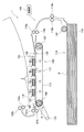
図1は、本発明の一実施形態である記録装置であるカラーインクジェットプリンタの概略構成図である。このカラーインクジェットプリンタ1(以下、プリンタ1とする)は、4つの液体吐出ヘッド2を有している。これらの液体吐出ヘッド2は、印刷用紙Pの搬送方向に沿って並べられ、プリンタ1に固定されている。液体吐出ヘッド2は、図1の手前から奥へ向かう方向に細長い形状を有している。
FIG. 1 is a schematic configuration diagram of a color inkjet printer which is a recording apparatus according to an embodiment of the present invention. This color inkjet printer 1 (hereinafter referred to as printer 1) has four
プリンタ1には、印刷用紙Pの搬送経路に沿って、給紙ユニット114、搬送ユニット120および紙受け部116が順に設けられている。また、プリンタ1には、液体吐出ヘッド2や給紙ユニット114などのプリンタ1の各部における動作を制御するための制御部100が設けられている。
In the
給紙ユニット114は、複数枚の印刷用紙Pを収容することができる用紙収容ケース115と、給紙ローラ145とを有している。給紙ローラ145は、用紙収容ケース115に積層して収容された印刷用紙Pのうち、最も上にある印刷用紙Pを1枚ずつ送り出すことができる。
The
給紙ユニット114と搬送ユニット120との間には、印刷用紙Pの搬送経路に沿って、二対の送りローラ118aおよび118b、ならびに、119aおよび119bが配置されている。給紙ユニット114から送り出された印刷用紙Pは、これらの送りローラによってガイドされて、さらに搬送ユニット120へと送り出される。
Between the
搬送ユニット120は、エンドレスの搬送ベルト111と2つのベルトローラ106および107を有している。搬送ベルト111は、ベルトローラ106および107に巻き掛けられている。搬送ベルト111は、2つのベルトローラに巻き掛けられたとき所定の張力で張られるような長さに調整されている。これによって、搬送ベルト111は、2つのベルトローラの共通接線をそれぞれ含む互いに平行な2つの平面に沿って、弛むことなく張られている。これら2つの平面のうち、液体吐出ヘッド2に近い方の平面が、印刷用紙Pを搬送する搬送面127である。
The
ベルトローラ106には、図1に示されるように、搬送モータ174が接続されている。搬送モータ174は、ベルトローラ106を矢印Aの方向に回転させることができる。また、ベルトローラ107は、搬送ベルト111に連動して回転することができる。したがって、搬送モータ174を駆動してベルトローラ106を回転させることにより、搬送ベルト111は、矢印Aの方向に沿って移動する。
As shown in FIG. 1, a
ベルトローラ107の近傍には、ニップローラ138とニップ受けローラ139とが、搬送ベルト111を挟むように配置されている。ニップローラ138は、図示しないバネによって下方に付勢されている。ニップローラ138の下方のニップ受けローラ139は、下方に付勢されたニップローラ138を、搬送ベルト111を介して受け止めている。2つのニップローラは回転可能に設置されており、搬送ベルト111に連動して回転する。
In the vicinity of the
給紙ユニット114から搬送ユニット120へと送り出された印刷用紙Pは、ニップローラ138と搬送ベルト111との間に挟み込まれる。これによって、印刷用紙Pは、搬送ベルト111の搬送面127に押し付けられ、搬送面127上に固着する。そして、印刷用紙Pは、搬送ベルト111の回転に従って、液体吐出ヘッド2が設置されている方向へと搬送される。なお、搬送ベルト111の外周面113に粘着性のシリコンゴムによる処理を施してもよい。これにより、印刷用紙Pを搬送面127に確実に固着させることができる。
The printing paper P sent out from the
4つの液体吐出ヘッド2は、搬送ベルト111による搬送方向に沿って互いに近接して配置されている。各液体吐出ヘッド2は、下端に液体吐出ヘッド本体13を有している。液体吐出ヘッド本体13の下面には、液体を吐出する多数の吐出孔8が設けられている(図3参照)。
The four liquid discharge heads 2 are arranged close to each other along the conveyance direction by the conveyance belt 111. Each
1つの液体吐出ヘッド2に設けられた吐出孔8からは、同じ色の液滴(インク)が吐出されるようになっている。各液体吐出ヘッド2の吐出孔8は一方方向(印刷用紙Pと平行で印刷用紙P搬送方向に直交する方向であり、液体吐出ヘッド2の長手方向)に等間隔で配置されているため、一方方向に隙間なく印刷することができる。各液体吐出ヘッド2から吐出される液体の色は、それぞれ、マゼンタ(M)、イエロー(Y)、シアン(C)およびブラック(K)である。各液体吐出ヘッド2は、液体吐出ヘッド本体13の下面と搬送ベルト111の搬送面127との間にわずかな隙間をおいて配置されている。
Liquid droplets (ink) of the same color are ejected from the ejection holes 8 provided in one
搬送ベルト111によって搬送された印刷用紙Pは、液体吐出ヘッド2と搬送ベルト111との間の隙間を通過する。その際に、液体吐出ヘッド2を構成する液体吐出ヘッド本体13から印刷用紙Pの上面に向けて液滴が吐出される。これによって、印刷用紙Pの上面には、制御部100によって記憶された画像データに基づくカラー画像が形成される。
The printing paper P transported by the transport belt 111 passes through the gap between the
搬送ユニット120と紙受け部116との間には、剥離プレート140と二対の送りローラ121aおよび121bならびに122aおよび122bとが配置されている。カラー画像が印刷された印刷用紙Pは、搬送ベルト111によって剥離プレート140へと搬送される。このとき、印刷用紙Pは、剥離プレート140の右端によって、搬送面127から剥離される。そして、印刷用紙Pは、送りローラ121a〜122bによって、紙受け部116に送り出される。このように、印刷済みの印刷用紙Pが順次紙受け部116に送られ、紙受け部116に重ねられる。
A
なお、印刷用紙Pの搬送方向についてもっとも上流側にある液体吐出ヘッド2とニップローラ138との間には、紙面センサ133が設置されている。紙面センサ133は、発光素子および受光素子によって構成され、搬送経路上の印刷用紙Pの先端位置を検出することができる。紙面センサ133による検出結果は制御部100に送られる。制御部100は、紙面センサ133から送られた検出結果により、印刷用紙Pの搬送と画像の印刷とが同期するように、液体吐出ヘッド2や搬送モータ174等を制御することができる。
Note that a
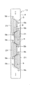
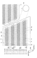
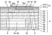
次に本発明の液体吐出ヘッドを構成する液体吐出ヘッド本体13について説明する。図2は、図1に示された液体吐出ヘッド本体13を示す上面図である。図3は、図2の一点鎖線で囲まれた領域の拡大上面図であり、液体吐出ヘッド本体13の一部である。図4は、図3と同じ位置の拡大透視図で、吐出孔8の位置が分かりやすいように、一部の流路を省略して描いている。なお、図3および図4において、図面を分かりやすくするために、圧電アクチュエータ基板21の下方にあって破線で描くべき加圧室10(加圧室群9)、しぼり12および吐出孔8を実線で描いている。図5は図3のV−V線に沿った縦断面図である。
Next, the liquid discharge head
液体吐出ヘッド本体13は、平板状の流路部材4と、流路部材4上に、アクチュエータユニットである圧電アクチュエータ基板21とを有している。圧電アクチュエータ基板21は台形形状を有しており、その台形の1対の平行対向辺が流路部材4の長手方向に平行になるように流路部材4の上面に配置されている。また、流路部材4の長手方向に平行な2本の仮想直線のそれぞれに沿って2つずつ、つまり合計4つの圧電アクチュエータ基板21が、全体として千鳥状に流路部材4上に配列されている。流路部材4上で隣接し合う圧電アクチュエータ基板21の斜辺同士は、流路部材4の短手方向について部分的にオーバーラップしている。このオーバーラップしている部分の圧電アクチェータユニット21を駆動することにより印刷される領域では、2つの圧電アクチュエータ基板21により吐出された液滴が混在して着弾することになる。
The liquid
流路部材4の内部には液体流路の一部であるマニホールド(共通流路)5が形成されている。マニホールド5は流路部材4の長手方向に沿って延び細長い形状を有しており、流路部材4の上面にはマニホールド5の開口5bが形成されている。開口5bは、流路部材4の長手方向に平行な2本の直線(仮想線)のそれぞれに沿って5個ずつ、合計10個形成されている。開口5bは、4つの圧電アクチュエータ基板21が配置された領域を避ける位置に形成されている。マニホールド5には開口5bを通じて図示されていない液体タンクから液体が供給されるようになっている。
A manifold (common channel) 5 which is a part of the liquid channel is formed inside the
流路部材4内に形成されたマニホールド5は、複数本に分岐している(分岐した部分のマニホールド5を副マニホールド5aということがある)。開口5bに繋がるマニホールド5は、圧電アクチュエータ基板21の斜辺に沿うように延在しており、流路部材4の長手方向と交差して配置されている。2つの圧電アクチュエータ基板21に挟まれた領域では、1つのマニホールド5が、隣接する圧電アクチュエータ基板21に共有されており、副マニホールド5aがマニホールド5の両側から分岐している。これらの副マニホールド5aは、流路部材4の内部の各圧電アクチュエータ基板21に対向する領域に互いに隣り合って液体吐出ヘッド本体13の長手方向に延在している。
The
流路部材4は、複数の加圧室10がマトリクス状(すなわち、2次元的かつ規則的)に形成されている4つの加圧室群9を有している。加圧室10は、角部にアールが施されたほぼ菱形の平面形状を有する中空の領域である。加圧室10は流路部材4の上面に開口するように形成されている。これらの加圧室10は、流路部材4の上面における圧電アクチュエータ基板21に対向する領域のほぼ全面にわたって配列されている。したがって、これらの加圧室10によって形成された各加圧室群9は圧電アクチュエータ基板21とほぼ同一の大きさおよび形状の領域を占有している。また、各加圧室10の開口は、流路部材4の上面に圧電アクチュエータ基板21が接着されることで閉塞されている。
The
本実施形態では、図3に示されているように、マニホールド5は、流路部材4の短手方向に互いに平行に並んだ4列のE1〜E4の副マニホールド5aに分岐し、各副マニホールド5aに繋がった加圧室10は、等間隔に流路部材4の長手方向に直線状に並ぶ加圧室10の列を構成し、その列は、短手方向に互いに平行に、隣り合うように4列配列されている。副マニホールド5aに繋がった加圧室10の並ぶ列は副マニホールド5aの両側に2列ずつ配列されている。
In the present embodiment, as shown in FIG. 3, the manifold 5 branches into four rows of E1-E4 sub-manifolds 5a arranged in parallel with each other in the short direction of the
全体では、マニホールド5から繋がる加圧室10は、等間隔に流路部材4の長手方向に並ぶ加圧室10の列を構成し、その加圧室列は、流路部材4の短手方向に互いに平行に、行方向に16列配列されている。各加圧室列に含まれる加圧室10の数は、アクチュエータである変位素子50の外形形状に対応して、その長辺側から短辺側に向かってしだいに少なくなるように配置されている。吐出孔8もこれと同様に配置されている。これによって、全体として長手方向に600dpiの解像度で画像形成が可能となっている。すなわち、各副マニホールド5aには平均すれば150dpiに相当する間隔で個別流路32が接続されている。これは、600dpi分の吐出孔8を4つ列の副マニホールド5aに分けて繋ぐ設計をする際に、各副マニホールド5aに繋がる個別流路32が等しい間隔で繋がるとは限らないため、マニホールド5aの延在方向、すなわち主走査方向に平均170μm(150dpiならば25.4mm/150=169μm間隔である)以下の間隔で個別流路32が形成されているということである。
As a whole, the pressurizing
圧電アクチュエータ基板21の上面における各加圧室10に対向する位置には後述する個別電極35がそれぞれ形成されている。個別電極35は加圧室10より一回り小さく、加圧室10とほぼ相似な形状を有しており、圧電アクチュエータ基板21の上面における加圧室10と対向する領域内に収まるように配置されている。
流路部材4の下面には多数の吐出孔8が形成されている。これらの吐出孔8は、流路部材4の下面側に配置された副マニホールド5aと対向する領域を避けた位置に配置されている。また、これらの吐出孔8は、流路部材4の下面側における圧電アクチュエータ基板21と対向する領域内に配置されている。これらの吐出孔群7は圧電アクチュエータ基板21とほぼ同一の大きさおよび形状の領域を占有しており、対応する圧電アクチュエータ基板21の変位素子50を変位させることにより吐出孔8から液滴が吐出できる。吐出孔8の配置については後で詳述する。そして、それぞれの領域内の吐出孔8は、流路部材4の長手方向に平行な複数の直線に沿って等間隔に配列されている。
A large number of discharge holes 8 are formed in the lower surface of the
液体吐出ヘッド本体13に含まれる流路部材4は、複数のプレートが積層された積層構造を有している。これらのプレートは、流路部材4の上面から順に、キャビティプレート22、ベースプレート23、アパーチャ(しぼり)プレート24、サプライプレート25、26、マニホールドプレート27、28、29、カバープレート30およびノズルプレート31である。これらのプレートには多数の孔が形成されている。各プレートは、これらの孔が互いに連通して個別流路32および副マニホールド5aを構成するように、位置合わせして積層されている。液体吐出ヘッド本体13は、図5に示されているように、加圧室10は流路部材4の上面に、副マニホールド5aは内部の下面側に、吐出孔8は下面にと、個別流路32を構成する各部分が異なる位置に互いに近接して配設され、加圧室10を介して副マニホールド5aと吐出孔8とが繋がる構成を有している。
The
各プレートに形成された孔について説明する。これらの孔には、次のようなものがある。第1に、キャビティプレート22に形成された加圧室10である。第2に、加圧室10の一端から副マニホールド5aへと繋がる流路を構成する連通孔である。この連通孔は、ベースプレート23(詳細には加圧室10の入り口)からサプライプレート25(詳細には副マニホールド5aの出口)までの各プレートに形成されている。なお、この連通孔には、アパーチャプレート24に形成されたしぼり12と、サプライプレート25、26に形成された個別供給流路6とが含まれている。
The holes formed in each plate will be described. These holes include the following. First, the pressurizing
第3に、加圧室10の他端から吐出孔8へと連通する流路を構成する連通孔であり、この連通孔は、以下の記載においてディセンダ(部分流路)と呼称される。ディセンダは、ベースプレート23(詳細には加圧室10の出口)からノズルプレート31(詳細には吐出孔8)までの各プレートに形成されている。第4に、副マニホールド5aを構成する連通孔である。この連通孔は、マニホールドプレート27〜30に形成されている。
Third, there is a communication hole constituting a flow path communicating from the other end of the pressurizing
このような連通孔が相互に繋がり、副マニホールド5aからの液体の流入口(副マニホールド5aの出口)から吐出孔8に至る個別流路32を構成している。副マニホールド5aに供給された液体は、以下の経路で吐出孔8から吐出される。まず、副マニホールド5aから上方向に向かって、個別供給流路6を通り、しぼり12の一端部に至る。次に、しぼり12の延在方向に沿って水平に進み、しぼり12の他端部に至る。そこから上方に向かって、加圧室10の一端部に至る。さらに、加圧室10の延在方向に沿って水平に進み、加圧室10の他端部に至る。そこから少しずつ水平方向に移動しながら、主に下方に向かい、下面に開口した吐出孔8へと進む。
Such communication holes are connected to each other to form an
圧電アクチュエータ基板21は、図5に示されるように、2枚の圧電セラミック層21a、21bからなる積層構造を有している。これらの圧電セラミック層21a、21bはそれぞれ20μm程度の厚さを有している。圧電アクチュエータ基板21全体の厚さは40μm程度であり、100μm以下であることにより、変位量を大きくすることができる。圧電セラミック層21a、21bのいずれの層も複数の加圧室10を跨ぐように延在している(図3参照)。これらの圧電セラミック層21a、21bは、強誘電性を有するチタン酸ジルコン酸鉛(PZT)系のセラミックス材料からなる。
As shown in FIG. 5, the
圧電アクチュエータ基板21は、Ag−Pd系などの金属材料からなる共通電極34、Au系などの金属材料からなる個別電極35を有している。個別電極35は上述のように圧電アクチュエータ基板21の上面における加圧室10と対向する位置に配置されている。個別電極35の一端は、加圧室10と対向する領域外に引き出されて引出電極35bになっており、引出電極35bの上には接続電極36が形成されている。接続電極36は例えばガラスフリットを含む金からなり、厚さが15μm程度で凸状に形成されている。また、接続電極36は、図示されていないFPC(Flexible Printed Circuit)に設けられた電極と電気的に接合されている。
The
詳細は後述するが、個別電極35には、制御部100から外部配線であるFPC(Flexible Printed Circuit)を通じて駆動信号(駆動電圧)が供給される。駆動信号は、印刷媒体Pの搬送速度と同期して一定の周期で供給される。共通電極34は、圧電セラミック層21aと圧電セラミック層21bとの間の領域に面方向のほぼ全面にわたって形成されている。すなわち、共通電極34は、圧電アクチュエータ基板21に対向する領域内の全ての加圧室10を覆うように延在している。共通電極34の厚さは2μm程度である。共通電極34は図示しない領域において接地され、グランド電位に保持されている。本実施形態では、圧電セラミック層21b上において、個別電極35からなる電極群を避ける位置に個別電極35とは異なる表面電極(不図示)が形成されている。表面電極は、圧電セラミック層21bの内部に形成されたスルーホールを介して共通電極34と電気的に接続されているとともに、多数の個別電極35と同様に外部配線と接続されている。
Although details will be described later, a drive signal (drive voltage) is supplied from the
なお、後述のように、個別電極35に選択的に所定の駆動信号が供給されることにより、この個別電極35に対応する加圧室10内の液体に圧力が加えられる。これによって、個別流路32を通じて、対応する液体吐出口8から液滴が吐出される。すなわち、圧電アクチュエータ基板21における各加圧室10に対向する部分は、各加圧室10および液体吐出口8に対応する個別の変位素子50(アクチュエータ)に相当する。つまり、2枚の圧電セラミック層からなる積層体中には、図5に示されているような構造を単位構造とする変位素子50が加圧室10毎に、加圧室10の直上に位置する振動板21a、共通電極34、圧電セラミック層21b、個別電極35により作り込まれており、圧電アクチュエータ基板21には変位素子50が複数含まれている。なお、本実施形態において1回の吐出動作によって液体吐出口8から吐出される液体の量は5〜7pL(ピコリットル)程度である。
As will be described later, when a predetermined drive signal is selectively supplied to the
平面視したとき、個別電極35は加圧室10と重なるように配置されており、加圧室10の中央に位置している部位の、個別電極35と共通電極34とに挟まれている圧電セラミック層21bは、圧電アクチュエータ基板21の積層方向に分極されている。分極の向きは上下どちらに向かっていてもよく、その方向に対応し駆動信号を与えることで駆動できる。
When viewed in a plan view, the
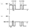
本実施形態における駆動信号を、図6(a)および(b)を用いて説明する。図6(a)は駆動信号であり、図6(b)は、その駆動信号を加えた際に生じる変位素子の変位である。なお、実際の駆動信号には、信号の立ち上がり、立ち下がりなどの信号のなまりが生じることがあるが、図ではそのようなものが含まれない、模式的なものを示している。また、実際の変位は、前記信号のなまりに対応した変位のなまりや、加圧室10内の液体および変位素子50自身が変形し難いことによる変位のなまりや、後述する加圧室10内の液体から受ける力などの外力により生じる変位が含まれるが、図ではそのようなものが含まれない、模式的なものを示している。これは、なまりのない信号を入力した際の、加圧室10に液体が入っていない状態の変位に相当する。
The drive signal in this embodiment is demonstrated using FIG. 6 (a) and (b). FIG. 6A shows the drive signal, and FIG. 6B shows the displacement of the displacement element that occurs when the drive signal is applied. Note that the actual drive signal may have signal rounding such as rising and falling of the signal, but the figure shows a schematic signal that does not include such a signal. Further, the actual displacement may be a displacement corresponding to the signal round, a displacement due to the liquid in the pressurizing
本実施形態における駆動信号は、メインパルスとメインパルスの後に送られるキャンセルパルスとを含んでいる。メインパルスは引き打ちと呼ばれる吐出駆動を行なうものである。また、メインパルスの前にプレパルスを含んでもよい。 The drive signal in this embodiment includes a main pulse and a cancel pulse sent after the main pulse. The main pulse performs discharge driving called pulling. Further, a pre-pulse may be included before the main pulse.
まず、メインパルスについて説明する。メインパルスは、予め個別電極35を共通電極34より高い電圧V1(V(ボルト)、以下で単位は省略することがある)にしておくことで、変位素子50が加圧室10側にd1((μm)、以下で単位は省略することがある)変位して、加圧室の体積が減少した状態で待機し、吐出要求がある場合、時刻t3で個別電極35を共通電極34と一旦同じ電位V2とすることで、変位をd2(=0)にして、加圧室10の体積を増加させ、その後、時刻t4で再び高電位とすることで、加圧室10の体積を減少させる。時刻t3で加圧室10の体積が増加することで、加圧室10内の液体は負圧になる。これにより、吐出孔8から加圧室10に向かう方向の圧力波が生じる。この圧力波が加圧室10に達し、反射されるタイミングに合わせて、時刻t4で加圧室10の体積が減少させられる。これにより反射した圧力波と加圧室10の体積が減少したことにより生じる圧力波が重なって吐出孔8に向かって進み、液滴が吐出される。
First, the main pulse will be described. In the main pulse, the
なお、以上の説明は、t4と反射する時刻とが完全に一致している場合について説明しているが、実際には、これらの時刻はある程度ずれてもよい。個別流路32内において圧力波がしぼり12の加圧室10側の端から吐出孔8まで伝播する時間長さをAL(Acoustic Length)といい、これはしぼり12から吐出孔8までの液体の体積固有振動周期の半分でもある。理想的状態ではt4−t3をALと一致させることで、液体吐出速度は最大になると考えられるが、実際にはt4−t3を0.7AL〜1.3AL程度の範囲にして使用される。ALは、流路の形状と液体の物性とから算出することもできるし、t4−t3の値を変えて吐出試験を行ない、液滴の速度がもっとも速くなる時間として、実験的に求めることもできる。なお、図1〜5に示した個別流路32のALは約6.7μsである。
In the above description, the case where t4 and the reflection time completely coincide is described, but in actuality, these times may be shifted to some extent. The length of time during which the pressure wave propagates from the end of the pressurizing
以上のようなメインパルスにより、液滴の吐出は可能であるが、本実施形態では、メインパルスの後に、キャンセルパルスを送る。キャンセルパルスは、メインパルスの後の時刻t5で電圧V2を加え、加圧室10の体積を増加させた後、時刻t6で電圧V1を加え、加圧室10の体積を減少させる。キャンセルパルスの長さt6−t5は、メインパルスの長さt4−t3より短く設定される。
Although droplets can be ejected by the main pulse as described above, in this embodiment, a cancel pulse is sent after the main pulse. The cancel pulse applies voltage V2 at time t5 after the main pulse to increase the volume of the pressurizing
キャンセルパルスは、例えば、次のような理由により加えられる。前述の説明では、吐出孔8に達した圧力波により、液滴が吐出されると簡単に説明したが、より詳しくは、吐出孔8から先に伸びる液柱が形成され、この液柱の後端がちぎれて、液柱が飛翔していくことになる。この際、液柱の後端部の液体の速度は、液柱の中央部の液体の速度と比較して遅くなっている場合があり、液柱の後端部と液柱の中央部とが別々の液滴になってしまう分滴が生じることがある。これらの液滴が印刷用紙Pの別々の場所に着弾すると、本来1つの画素となるべき吐出により2つの画素が形成されてしまい、記録精度が低くなることがある。このような場合、キャンセルパルスにより、メインパルスにより形成された液柱の後端部分を吐出孔8に引き込んだり、液柱の後端部分となるはずの圧力波をディセンダ内部で引き戻すことにより、分滴を抑制することができる。 The cancel pulse is applied for the following reason, for example. In the above description, it has been briefly described that a droplet is ejected by a pressure wave reaching the ejection hole 8, but more specifically, a liquid column extending from the ejection hole 8 is formed. The edge will tear off and the liquid column will fly. At this time, the speed of the liquid at the rear end of the liquid column may be slower than the speed of the liquid at the center of the liquid column, and the rear end of the liquid column and the center of the liquid column Drops may occur that become separate droplets. When these droplets land on different places on the printing paper P, two pixels are formed by ejection that should originally become one pixel, and the recording accuracy may be lowered. In such a case, the cancel pulse causes the rear end portion of the liquid column formed by the main pulse to be drawn into the discharge hole 8, or the pressure wave that should be the rear end portion of the liquid column is pulled back inside the descender. Drops can be suppressed.
キャンセルパルスの長さt6−t5は、短いと上述の効果が小さく、長くなると引き戻しの効果が大きくなりすぎて、液滴の吐出速度が下がってしまったり、長くなることでALに近づくとキャンセルパルスにより吐出が生じたりする。そのためキャンセルパルスの長さは、図1〜5に示した液体吐出ヘッドでは、1.0〜2.5μs程度に設定される。また、その長さは、上述の理由で、0.1AL以上、好ましくは0.2AL以上とされ、0.5AL以下、好ましくは0.4AL以下、より好ましくは0.3AL以下にされる。 When the cancel pulse length t6-t5 is short, the above-described effect is small. When the cancel pulse length t6-t5 is long, the pull back effect becomes too large, and the discharge speed of the droplet decreases or becomes long. May cause discharge. Therefore, the length of the cancel pulse is set to about 1.0 to 2.5 μs in the liquid ejection head shown in FIGS. Further, the length is 0.1 AL or more, preferably 0.2 AL or more, for the above-mentioned reason, 0.5 AL or less, preferably 0.4 AL or less, more preferably 0.3 AL or less.
メインパルスからキャンセルパルスまでの時間t5−t4は、液柱を引き込む動作をさせるために、AL以下の時間に設定される。t5−t4が短いと液柱を引き戻す効果が大きくなりすぎて、液滴の吐出速度が下がるため、t5−t4は0.1AL以上にすることが好ましく、特に0.25AL以上にすることが好ましい。また、t2−t1が短いと液柱を引き戻す効果が小さくなるため、t5−t4は0.6AL以下にすることが好ましく、特に0.5AL以下にすることが好ましい。 The time t5-t4 from the main pulse to the cancel pulse is set to a time equal to or shorter than AL in order to perform the operation of drawing the liquid column. If t5-t4 is short, the effect of pulling back the liquid column becomes too great, and the droplet discharge speed is lowered. Therefore, t5-t4 is preferably 0.1 AL or more, particularly preferably 0.25 AL or more. . In addition, if t2-t1 is short, the effect of pulling back the liquid column is small, so t5-t4 is preferably 0.6 AL or less, and particularly preferably 0.5 AL or less.
駆動信号には、上述のメインパルスとキャンセルパルスとが含まれる。駆動信号は、基本的に、印刷用紙P上に1つの画素を形成するために送られるもので、所定の駆動周期毎に送られたり、送られなかったりすることで、画素を記録させたり、記録させなかったりする。メインパルスとキャンセルパルスの組み合わせは、もっとも単純なものでは、メインパルスの後にキャンセルパルスが送られる。他に、複数のメインパルスを送った後に、キャンセルパルスを送ったり、メインパルスの後にキャンセルパルスを送るパルスの組を2回以上送ってもよい。そのような場合、各メインパルスで吐出された液滴は、飛翔中に一体化して1つの液滴になったり、印刷用紙P上で広がって一体化するなどして、印刷用紙P上で1つの画素を形成する。 The drive signal includes the main pulse and the cancel pulse described above. The drive signal is basically sent to form one pixel on the printing paper P. The drive signal is sent or not sent every predetermined drive cycle, so that the pixel is recorded, Do not let me record. The simplest combination of main pulse and cancel pulse is such that a cancel pulse is sent after the main pulse. In addition, after sending a plurality of main pulses, a cancel pulse may be sent, or a set of pulses for sending a cancel pulse after the main pulse may be sent twice or more. In such a case, the droplets ejected by each main pulse are integrated into one droplet during the flight, or spread and integrated on the printing paper P, and so on. One pixel is formed.
駆動信号には、さらに、プレパルスが含まれていてもよい。プレパルスは、メインパルスの前の時刻t1で電圧V2を加え、加圧室10の体積を増加させた後、時刻t2で電圧V1を加え、加圧室10の体積を減少させる。プレパルスの長さt2−t1は、メインパルスの長さt4−t3より短く設定される。
The drive signal may further include a pre-pulse. In the pre-pulse, the voltage V2 is applied at time t1 before the main pulse to increase the volume of the pressurizing
プレパルスは、例えば、次のような理由により加えられる。1つには、メインパルスで生じた液柱の先端部の液体の速度が、液柱の中央部の液体の速度と比較して速くなってしまい、液柱の先端部と液柱の中央部とが別々の液滴になってしまう分滴が生じることを抑制することである。メインパルスにより生じる液体の体積速度が、標準的には、しだいに大きくなり、最大に達した後、小さくなっていくものであることから、このようなことは比較的生じ難いのであるが、メインパルスの波形を複雑なものにした場合や、後述の残留振動やクロストークの影響により生じることがある。そのような場合、メインパルスにより生じる圧力波の先端部分が生じる際に、プレパルスによる振動が、液体が吐出孔8に向かい難い状態にされていることにより、メインパルスにより生じる圧力波の先端部分の体積速度が小さくなり、分滴が生じ難くなる。 The prepulse is applied for the following reason, for example. For one thing, the velocity of the liquid at the tip of the liquid column generated by the main pulse is higher than the velocity of the liquid at the center of the liquid column, and the tip of the liquid column and the center of the liquid column. Is to suppress the occurrence of droplets that become separate droplets. This is relatively unlikely to occur because the volume velocity of the liquid produced by the main pulse typically increases gradually and then decreases after reaching the maximum. This may occur when the pulse waveform is complicated or due to the effects of residual vibration and crosstalk described later. In such a case, when the tip part of the pressure wave generated by the main pulse is generated, the vibration due to the pre-pulse is in a state in which the liquid is difficult to go to the discharge hole 8, so that the tip part of the pressure wave generated by the main pulse is reduced. The volume velocity is reduced, and droplets are less likely to occur.
プレパルスを加える別の理由は、前の画素を形成した吐出の後に残っている液体の残留振動の影響を小さくするためである。残留振動は、前の駆動周期において、液体を吐出したかどうかや、諧調表現などのために異なる複数の駆動信号を用いている場合に、どの駆動信号を使用したか、さらには、周囲の変位素子50の変位や、マニホールド5から伝わってくる液体の振動により様々な影響が合わさったものであるため、一定の状態とはなり難い。残留振動の状態は、メインパルスにより生じる圧力波の状態を変動させるため、吐出特性のばらつきの原因となる。そこでメインパルスの前にプレパルスを送ることで、メインパルスが送られる際の残留振動の状態は、主にプレパルスで生じた振動が残っている状態となるため、プレパルス前の残留振動がメインパルスに与える影響が相対的に小さくなり、吐出特性のばらつきを小さくできる。
Another reason for applying the pre-pulse is to reduce the influence of the residual vibration of the liquid remaining after the discharge forming the previous pixel. Residual vibration is the result of whether or not liquid was discharged in the previous drive cycle, which drive signal was used when different drive signals were used for gradation expression, etc. Since various influences are combined by the displacement of the
残留振動の影響を小さくすることは、駆動信号の長さやALに対する、駆動周期の長さの比が小さい場合は重要である。駆動周期が、駆動信号(複数の異なる駆動信号の用いる場合は、もっとも長い駆動信号)の3倍以下、特に2倍以下になれば残留振動の影響は大きくなる。なお、駆動周期が駆動信号の2倍以下であるというとは、駆動信号が送られている間の時間の長さよりも、駆動信号間の時間の長さの方が短いということである。また、別の言い方をすると、駆動信号間の時間の長さがALの4倍以下、特に2倍以下になれば残留振動の影響は大きくなる。ALは固有振動周期の半分であり、ALの4倍以下、2倍以下とは、それぞれ、固有振動2周期分、1周期分にあたり、固有振動が減衰する時間がそれだけしかなく、短いということである。また、駆動信号の長さは、メインパルスが1つであっても、AL以上であり、2AL程度もしくはそれより長くなるので、駆動周期が、ALの6倍以下、特に4倍以下になれば残留振動の影響は大きくなる。 Reducing the influence of residual vibration is important when the ratio of the length of the drive cycle to the length of the drive signal or AL is small. When the drive cycle is 3 times or less, especially 2 times or less of the drive signal (the longest drive signal when a plurality of different drive signals are used), the influence of the residual vibration becomes large. Note that the drive period being twice or less the drive signal means that the time between the drive signals is shorter than the time during which the drive signals are sent. In other words, if the length of time between drive signals is 4 times or less, especially 2 times or less of AL, the influence of residual vibration becomes large. AL is half of the natural vibration period. Less than 4 times and 2 times or less of AL means that the natural vibration is attenuated only for 2 periods and 1 period, respectively, and it is short. is there. Further, the length of the drive signal is not less than AL even if there is one main pulse, and is about 2 AL or longer, so if the drive cycle is not more than 6 times AL, especially not more than 4 times. The effect of residual vibration is increased.
いずれの効果を目的としても、プレパルスの長さt2−t1は、短いと上述の効果が小さく、長くなるとメインパルスの圧力波の先端の体積速度を減ずる効果が大きくなりすぎて、液滴の吐出速度が下がってしまったり、長くなることでALに近づくとプレパルスによる吐出が生じたりする。そのためプレパルスの長さは、図1〜5に示した液体吐出ヘッドでは、0.5〜2.5μs程度に設定される。また、その長さは、上述の理由に、0.05AL以上、好ましくは0.1AL以上とされ、0.5AL以下、好ましくは0.4AL以下、より好ましくは0.3AL以下にされる。 For any purpose, if the prepulse length t2-t1 is short, the above-described effect is small, and if it is long, the effect of reducing the volume velocity at the tip of the pressure wave of the main pulse becomes too large, and droplet discharge When the speed decreases or becomes longer, when it approaches AL, ejection by pre-pulse occurs. Therefore, the length of the pre-pulse is set to about 0.5 to 2.5 μs in the liquid ejection head shown in FIGS. Further, the length is set to 0.05 AL or more, preferably 0.1 AL or more, for reasons described above, 0.5 AL or less, preferably 0.4 AL or less, more preferably 0.3 AL or less.
プレパルスからメインパルスまでの時間t3−t2は、AL以下の時間にすれば、メインパルスで生じる圧力波の先端の体積速度を減ずることができる。また、残留振動の影響を抑制しようとする場合、そもそも駆動周期が短いため、メインパルスから時間的に離す余裕はあまりない。t3−t2が短いと、液滴の吐出速度が下がったり、分滴を抑制するプレパルスの効果が弱くなるため、t3−t2は0.05AL以上にすることが好ましく、特に0.1AL以上にすることが好ましい。また、t3−t2が長いとプレパルスの効果が弱くなるため、t3−t2は0.6AL以下にすることが好ましく、特に0.4AL以下にすることが好ましい。 If the time t3-t2 from the pre-pulse to the main pulse is set to a time equal to or shorter than AL, the volume velocity at the tip of the pressure wave generated by the main pulse can be reduced. Further, when trying to suppress the influence of residual vibration, the drive cycle is short in the first place, so there is not much room for time separation from the main pulse. If t3-t2 is short, the droplet ejection speed decreases and the effect of the prepulse for suppressing the droplets is weakened. Therefore, t3-t2 is preferably 0.05 AL or more, particularly 0.1 AL or more. It is preferable. Moreover, since the effect of a prepulse will become weak when t3-t2 is long, it is preferable to make t3-t2 into 0.6 AL or less, and it is especially preferable to make it into 0.4 AL or less.
なお、以上の説明は、電圧を2つの値の間で切り替えて、変位素子50を2つの変位位置の間を動かす例を示したが、加圧室10の体積変化が上述の吐出動作をするものであれば、駆動電圧は、さらに多くの電圧値を使用したり、電圧の変化率の調整などをしてもよい。
In the above description, the voltage is switched between two values and the
このような駆動信号により記録を行なうとクロストークが生じることがある。主なクロストークとしては、圧変位素子50が変位する際に、変位素子50が収縮するので、その応力が隣接する変位素子に影響するもの、加圧室10の中の液体の振動が流路部材4を通じて隣接する加圧室10に伝わるもの、加圧室10の中の液体の振動がしぼり12を介して副マニホールド5aに伝わり、さらに副マニホールド5aに繋がっている加圧室10に伝わるものがある。このようなクロストークを抑制するために、駆動信号に遅延時間の遅延を与えて変位素子50に送ることが考えられる。これは、ある時刻tに駆動信号を送るところを時刻(t+遅延時間)に駆動信号を送るものであり、マトリックス状に配置された加圧室10のうち隣接した加圧室10に繋がっている変位素子50に同時に駆動信号を送らないようにすることで、前述の主なクロストークのうち最初の2つのクロストークを抑制することに効果がある。
When recording is performed using such a drive signal, crosstalk may occur. The main crosstalk is that when the
なお、ここで言う隣接する加圧室10とは、詳細には、異なる加圧室列に属する加圧室10であって隣接する加圧室10のことであり、また、加圧室列が並ぶ方向である行方向に隣り合っている加圧室10のことである。さらに、間の距離がもっとも近い加圧室10のことであり、より具体的には、略菱形(より一般的には略平行四辺形の)の辺が対向して隣り合う加圧室10のことである。そして、このような駆動は、例えば、図3のF1、F3、F5、F7、F9、F11、F13、F15の加圧室列に対応する変位素子50に遅延させない駆動信号を送り、F2、F4、F6、F8、F10、F12、F14、F16の加圧室列に対応する変位素子50に遅延を与えて駆動信号を送り始めればよい。
In addition, the
加圧室列間に遅延を与えて駆動信号を送るとは、上述のことを意味する。加圧室列が3列以上ある場合、一番最初に駆動される基準の加圧室列に対して、他の行の加圧室列に遅延時間が設定される。また、行方向に隣り合っている2つの加圧室列には、(遅延を与えない場合も、遅延時間が0であると考えて)異なる遅延時間が設定される。その2つの加圧室列のみに着目すれば、遅延時間の長い加圧室列には、遅延時間の短い加圧室列に対して、2つの加圧列の遅延時間の差の遅延を与えられることになる。 Sending a drive signal with a delay between the pressurizing chamber rows means the above. When there are three or more pressurizing chamber columns, a delay time is set for the pressurizing chamber columns in the other rows with respect to the reference pressurizing chamber column that is driven first. Also, different delay times are set for two pressurizing chamber columns adjacent in the row direction (assuming that the delay time is 0 even when no delay is given). Focusing only on the two pressurization chamber rows, the pressurization chamber row having a long delay time is given a delay of the difference between the delay times of the two pressurization rows to the pressurization chamber row having a short delay time. Will be.
ここで言う駆動信号は、一連の電圧変化のうち、最初に待機状態とは異なる電圧が加わり始めてから、最後に待機状態に戻るまでの信号のことを指す。すなわち、遅延を与えて駆動信号を送り始めるとは、最初に加わる電圧変化のタイミングを遅らせるよう、遅延させて駆動信号を送ることを意味する。これには、例えば、電圧が待機状態から変わり始めてから待機状態に戻るまでの電圧変化のデータを記録しておき、そのデータに基づいて、駆動波形を送るタイミングを、タイマーやクロックなどを用いて送らせればよい。また、記録しておくデータの最初の部分を、待機状態と同じ電圧が加わるようにしておき、その後に、電圧変化する駆動信号のデータを入れておくようにしても、駆動信号を送り始めるタイミングを遅延させることができる。 The drive signal here refers to a signal from the beginning of applying a voltage different from the standby state to the standby state in the series of voltage changes. That is, giving a delay and starting to send a drive signal means sending the drive signal with a delay so as to delay the timing of the first voltage change. For this, for example, voltage change data from when the voltage starts to change from the standby state to when the voltage returns to the standby state is recorded, and the timing for sending the drive waveform based on the data is recorded using a timer or a clock. Send it. In addition, even if the same voltage as that in the standby state is applied to the first part of the data to be recorded, and the drive signal data that changes in voltage is subsequently input, the timing to start sending the drive signal Can be delayed.
また、上述の実施形態以外においても、複数の加圧室列を有する液体吐出ヘッド2において、1つの加圧室列に属する加圧室10に対応した変位素子50に同時に駆動信号を送り(以下で、このことを、単に、加圧室列に駆動信号を送ると言うことがある)、隣接する加圧室列には、少なくとも一方に遅延させた駆動信号を送ることで、同時に駆動信号を送らないようにすることで、駆動方法を簡単に(これにより、駆動信号の制御をするドライバICなどの構造が簡単になり、安価になる)するとともに、クロストークを低減できる。なお、ここでは、画像を印刷するために、電圧変化のある液滴を吐出させる駆動信号を送ることに加えて、電圧変化がなく液滴を吐出させない信号を送ることも合わせて、加圧室列に駆動信号を送る表現している。また、電圧変化がなく液滴を吐出させない信号以外に、電圧変化するが液滴を吐出させない信号を送って、液体を振動させて、液体中の固形成分なでの固着を抑制してもよい。
In addition to the embodiments described above, in the
さらに、駆動信号を遅延させると、そのまままでは、吐出した液滴の着弾位置がずれることになる。遅延時間の値により、着弾位置のずれが画質に与える影響が許容できる範囲であれば、そのまま使用してもよいし、遅延時間に応じて吐出孔8の配置をずらすなどして、着弾位置の精度を高くしてもよい。 Further, if the drive signal is delayed, the landing position of the ejected liquid droplet is shifted until it is left as it is. If the deviation of the landing position can tolerate the influence on the image quality depending on the value of the delay time, it can be used as it is, or the position of the landing position can be changed by shifting the arrangement of the discharge holes 8 according to the delay time. The accuracy may be increased.
メインパルスとキャンセルパルスと、必要に応じてプレパレスとを含む駆動信号を用いて、一部の駆動信号を遅延させて送る制御を行なって印刷していると、遅延のさせ方により印刷のばらつきの程度が変わる場合ある。これは、液滴の吐出速度にばらつきが生じた結果であり、その原因は次のように考えられる。 When printing is performed by using a drive signal including a main pulse, a cancel pulse, and a preparatory as necessary, and a part of the drive signal is delayed and sent, printing may vary depending on the delay method. The degree may vary. This is a result of variations in the droplet ejection speed, and the cause is considered as follows.
複数の加圧室10の上部は、1つの圧電アクチュエータ基板21で覆われており、変位素子50が変位する場合、その変位の状態に応じて、繋がっている圧電アクチュエータ基板21を通じて、隣接する変位素子に影響が生じる。例えば、変位素子50が屈曲することで変位素子50が平らである場合よりも加圧室20の体積を減じている場合、隣接する変位素子50は、屈曲している変位素子50に平面方向に引っ張られている状態になるため、通常よりも変位し難い状態となっている。そのような場合、同じ駆動信号を与えても、通常よりも変位量が小さくなるので、吐出特性は変動する。
The upper portions of the plurality of pressurizing
したがって、変位させる際には、周囲の変位素子50の状態が同じようにするのが好ましい。それは、例えば、1つの変位素子50に駆動信号が送られる際には、遅延時間の設定により、隣接する変位素子50に駆動信号が送られない状態にすればよいのであるが、そのような方法では、限られた1駆動周期の中に駆動信号を収めきれなくなってしまう。
Therefore, it is preferable that the surrounding
そこで、本発明の駆動方法では、キャンセルパルスあるいはプレパルスが送られる際の、隣接する変位素子50の状態、すなわち、隣接する変位素子50に送られる駆動信号の状態ができるだけ一定に近くなるようにする。これは、メインパルスが体積を増やす電圧変化と体積を減らす電圧変化とが、生じる圧力波が強め合うよう(位相差が−90〜90度で0度に近い)にされており、液体に与えるエネルギーが大きいのに対し、キャンセルパルスやプレパルスは、体積を増やす電圧変化と体積を減らす電圧変化とが、生じる圧力波が弱め合うよう(位相差が90〜270度で180度に近い)にされており、液体に与えるエネルギーが小さいので、外乱に対する変動が大きくなるからである。また、メインパルス自体は、キャンセルパルスあるはプレパルスにより安定化されており、変動を受け難い状態となっているので、キャンセルパルスあるはプレパルスの方が、相対的に変動の影響を受けやすい状態となっているからである。
Therefore, in the driving method of the present invention, the state of the
また、印刷された状態において、吐出特性のばらつきが目立ち易いのは、同一の画素サイズが連続して形成された場合である。すなわち、写真ような画像を、画素サイズにより諧調差を付けて印刷する場合、印刷状態にわずかな変動があっても、元の画像に含まれている濃淡の情報と比較すれば、その変動は小さいので、人間には近くされ難い。これに対して、同一の画素サイズが連続して印刷される場合、文字や複雑な画像を印刷した場合によりも、吐出特性の変動が人間に知覚され易い。そこで、隣り合っている加圧室10から吐出孔8を通じて吐出させる際の、駆動信号のキャンセルパスルあるいはプレパルスの状態を、吐出特性への影響が少ない状態にすれば、吐出ばらつきを小さくできる。以降説明する駆動方法は、一般的な印刷においても有用であるが、特にそのような印刷状態、すなわち同一サイズの画素が連続して配置されるような印刷において有用である。特に、諧調表現が可能な液体吐出ヘッドにおいては、もっとも大きな画素サイズの画素など用いて印刷する完全なベタ印刷よりも、中間諧調にあたる画素サイズの画素を用いて、画素の間に印刷されない部分を残しながら(つまりベタ印刷ではないということである)、画素を並べて印刷していると目立ち易いため、そのような場合、つまり中間諧調の画素サイズを連続して印刷する場合に、キャンセルパスルあるいはキャンセルパルスの状態を、吐出特性への影響が少ない状態にすれば、吐出ばらつきを小さくできる。
In the printed state, the variation in ejection characteristics is conspicuous when the same pixel size is continuously formed. In other words, when printing an image such as a photograph with a gradation difference depending on the pixel size, even if there is a slight variation in the printing state, the variation is compared with the shading information included in the original image. Because it is small, it is difficult to be close to humans. On the other hand, when the same pixel size is continuously printed, even when characters or complex images are printed, fluctuations in ejection characteristics are easily perceived by humans. Therefore, if the cancel pulse or pre-pulse state of the drive signal at the time of discharging from the adjacent pressurizing
まず、メインパルスとキャンセルパルスとで構成された駆動信号において、キャンセルパルスを、隣接する変位素子50にパルス(メインパルスおよびキャンセルパルス)が送られていない状態で送るようにする場合を説明する。すなわち、印刷用紙P上で連続している画素を印刷する場合、もしくは、諧調表現をする際において、印刷用紙P上で連続している同一サイズの画素を印刷する場合、それらの画素となる液滴を吐出する駆動信号のキャンセルパルスを、隣接する変位素子50にパルスが送られていない状態で、送るようにする。その際、キャンセルパスを送るのを、隣接した変位素子50の駆動信号が終わった状態にすると、全ての駆動信号を送り終わるまでの時間が長くなってしまう。このため、キャンセルパルスは隣り合っている変位素子50の駆動信号のメインパルスとキャンセルパルスとの間に送られる。
First, a description will be given of a case where a cancel pulse is sent in a state in which no pulse (main pulse and cancel pulse) is sent to the
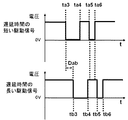
具体的な駆動信号を図7に示す。図7の駆動信号は、隣り合っている加圧室列にそれぞれ送られる、遅延時間の短い駆動信号と、遅延時時間の長い駆動信号である。別の言い方をすれば、遅延時間が長い駆動信号は、遅延時間の短い駆動信号に対して遅延が与えられている。遅延時間の短い駆動信号は、時刻ta3〜4のメインパルスと、時刻ta5〜6のキャンセルパルスとかならなる。遅延時間の短い駆動信号は、時刻tb3〜4のメインパルスと、時刻tb5〜6のキャンセルパルスとかならなる。それぞれの駆動信号は自体は同じ、すなわち、電圧差が同じで、時刻ta3からta4〜6までの時間の長さは、時刻tb3からtb4〜6までの時間の長さと同じである。ただし、それぞれの駆動信号は、形成される画素サイズが近くなるように、多少異なる駆動信号にしてもよい。遅延時間の短い駆動信号と、遅延時時間の長い駆動信号との遅延時間の差はDabである。 Specific drive signals are shown in FIG. The drive signals in FIG. 7 are a drive signal with a short delay time and a drive signal with a long delay time, which are sent to adjacent pressurizing chamber rows. In other words, a drive signal with a long delay time is given a delay with respect to a drive signal with a short delay time. The drive signal with a short delay time consists of a main pulse at times ta3-4 and a cancel pulse at times ta5-6. The drive signal with a short delay time consists of a main pulse at times tb3 to 4 and a cancel pulse at times tb5 to 6. Each drive signal itself is the same, that is, the voltage difference is the same, and the length of time from time ta3 to ta4-6 is the same as the length of time from time tb3 to tb4-6. However, the drive signals may be slightly different so that the pixel size to be formed is close. The difference in delay time between the drive signal with a short delay time and the drive signal with a long delay time is Dab.
そして、隣り合っている加圧室列のうち、遅延時間が短い駆動信号の時刻ta5〜6のキャンセルパルスは、遅延時間が長い駆動信号の、メインパルスとキャンセルパルスとの間である時刻tb4〜5の間に送られるとともに、遅延時間が長い駆動信号の時刻tb5〜6キャンセルパルスは、遅延時間が短い駆動信号のキャンセルパルスを送り終えた時刻ta6の後(より詳細には、次の駆動周期のメインパルスの前)に送られる。これにより、キャンセルパルスは、隣接する変位素子50にパルスが送られていない間に送られるため、それぞれのキャンセルパルスの働きに差異が生じ難いので、吐出特性の差を小さくできる。メインパルスが複数送られる駆動波形を用いる場合には、遅延時間が短い駆動信号のキャンセルパルスは、遅延時間が長い駆動信号の、メインパルスとメインパルスとの間に送ってもよい。
In addition, among the adjacent pressurizing chamber trains, the cancel pulse at the time ta5-6 of the drive signal with a short delay time is between the main pulse and the cancel pulse of the drive signal with a long delay time. 5 and the time tb5-6 cancel pulse of the drive signal having a long delay time is after the time ta6 when the cancel pulse of the drive signal having a short delay time has been sent (more specifically, the next drive cycle). Before the main pulse. Accordingly, since the cancel pulse is sent while the pulse is not sent to the
なお、プレパレスを含む駆動信号の場合も同様に、遅延時間が長い駆動信号のプレパルスは、遅延時間が短い駆動信号の、メインパルスとプレパルスとの間に送られるとともに、遅延時間が短い駆動信号のプレパルスは、遅延時間が長い駆動信号のプレパルスを送り出す前(より詳細には、前の駆動周期のキャンセルパルスの後)に送られることにより、プレパルスも、隣接する変位素子50にパルスが送られていない間に送られるため、それぞれのプレパルスの働きに差異が生じ難いので、吐出特性の差を小さくできる。
Similarly, in the case of a drive signal including a pre-pause, a pre-pulse of a drive signal having a long delay time is sent between the main pulse and the pre-pulse of a drive signal having a short delay time and a drive signal having a short delay time. The pre-pulse is sent before the pre-pulse of the drive signal having a long delay time (more specifically, after the cancel pulse of the previous drive cycle), so that the pre-pulse is also sent to the
より具体的には、駆動信号を、メインパルスの長さ(ta4−ta3)を8μs、メインパルスとキャンセルパルスの間隔(ta5−ta4)を4.5μs、キャンセルパルスの長さ(ta6−ta5)を1.8μsとし、16列の加圧室列の遅延時間を端から順に0μs(遅延無し)と2.5μsにすれば、上述の関係が満たされ、吐出特性のばらつきを小さくできる。なお、この駆動信号は、直径約30μmの画素となるように吐出するものである。600dpi(画素ピッチ約42μm)の印刷では、この画素サイズは中間諧調となり、吐出量のばらつきが目立ち易い画素サイズであるが、このような遅延時間にすることで、この画素サイズが並んだ印刷を行なっても印刷ばらつきが目立ち難くできる。これよりも画素サイズが大きくなる駆動信号や、小さくなる駆動信号を送るときも、これと同じ遅延時間で送れば、ドライバICの回路などが簡単になり好ましい。吐出量のばらつきが目立ち易い画素サイズで、ばらつきを低減できればよいので、それらの駆動信号では、上述の条件が成り立っていなくてもよいが、それらの駆動信号でも、上述の条件が成り立つようにすれば、より好ましい。そのために、駆動信号の種類によって遅延時間を変えてもよい。 More specifically, the drive signal has a main pulse length (ta4-ta3) of 8 μs, a main pulse-cancel pulse interval (ta5-ta4) of 4.5 μs, and a cancel pulse length (ta6-ta5). Is set to 1.8 μs, and the delay time of the 16 pressurizing chamber rows is set to 0 μs (no delay) and 2.5 μs in order from the end, the above relationship is satisfied, and variations in ejection characteristics can be reduced. The drive signal is discharged so as to form a pixel having a diameter of about 30 μm. In printing at 600 dpi (pixel pitch of about 42 μm), this pixel size is an intermediate tone, and the variation in the discharge amount is conspicuous. By using such a delay time, printing in which the pixel sizes are arranged is performed. Even if it is carried out, variations in printing can be made inconspicuous. When a drive signal with a larger pixel size or a drive signal with a smaller pixel size is sent, it is preferable to send the drive signal with the same delay time because the circuit of the driver IC is simplified. Since it is sufficient that the variation in the discharge amount is conspicuous and the variation can be reduced, the above conditions may not be satisfied in those drive signals, but the above conditions may be satisfied in these drive signals. More preferable. Therefore, the delay time may be changed depending on the type of drive signal.
続いて、プレパルスとメインパルスとキャンセルパルスとで構成された駆動信号において、キャンセルパルスあるいはプレパレスの一部を、隣接する変位素子50にパルス(メインパルスおよびキャンセルパルス)が送られている状態で送るようにする場合を説明する。上述したようにプレパルスおよびキャンセルパルスの両方を送るタイミングを、隣接する変位素子50にパルスが送られていない状態にしてもよいが、液体の吐出量が吐出速度を調整するなどの理由で駆動信号を変えようとしても、プレパルスおよびキャンセルパルスを送ることのできるタイミングが限られるため、タイミングをそのように調整するのは難しい場合がある。そこで、逆にキャンセルパルスあるいはプレパレスの一部を、隣接する変位素子50にパルスが送られている状態のタイミングで送る。
Subsequently, in the drive signal composed of the pre-pulse, the main pulse, and the cancel pulse, a part of the cancel pulse or the pre-palace is sent in a state where the pulses (main pulse and cancel pulse) are sent to the
プレパルスおよびキャンセルパルスは、基本的にメインパルスで吐出される液滴の量を少なくするように働くため、プレパルスおよびキャンセルパルスが、隣接する変位素子50の駆動信号のパルスが送られている状態で送られると、その働きが弱くなり、吐出量が増えることになる。人間の知覚の特性として、同じ程度画素サイズの違いの場合、一部が濃くなっている状態より、一部が薄くなっている状態の方が、知覚され易い。そこで、もっとも画素サイズが小さくなる、プレパルスおよびキャンセルパルスの両方が、隣接する変位素子50の駆動信号のパルスが送られている状態で送られることのないようにする。さらに、プレパルスおよびキャンセルパルスの働きを弱めて、画素サイズが小さくなる液滴を吐出さえないためには、メインパルスに近い側の電圧変化が、隣接する変位素子50の駆動信号のパルスが送られている状態で送られることのないようにする。
Since the pre-pulse and the cancel pulse basically work to reduce the amount of liquid droplets ejected by the main pulse, the pre-pulse and the cancel pulse are in a state where the pulse of the drive signal for the
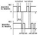
具体的な駆動信号を図8に示す。図8の駆動信号は、隣り合っている加圧室列にそれぞれ送られる、遅延時間の短い駆動信号と、遅延時時間の長い駆動信号である。遅延時間の短い駆動信号は、時刻tc1〜2のプレパルスと、時刻tc3〜4のメインパルスと、時刻tc5〜6のキャンセルパルスとかならなる。遅延時間の短い駆動信号は、時刻td1〜2のプレパルスと、時刻td3〜4のメインパルスと、時刻td5〜6のキャンセルパルスとかならなる。それぞれの駆動信号は自体は同じ、すなわち、電圧差が同じで、時刻tc13からtc2〜6までの時間の長さは、時刻td1からtd2〜6までの時間の長さと同じである。ただし、それぞれの駆動信号は、形成される画素サイズが近くなるように、多少異なる駆動信号にしてもよい。遅延時間の短い駆動信号と、遅延時時間の長い駆動信号との遅延時間の差はDcdである。 Specific drive signals are shown in FIG. The drive signals in FIG. 8 are a drive signal with a short delay time and a drive signal with a long delay time, which are sent to adjacent pressurizing chamber rows. The drive signal with a short delay time is composed of a pre-pulse at time tc1 to 2, a main pulse at time tc3 to 4, and a cancel pulse at time tc5 to 6. The drive signal with a short delay time is composed of a pre-pulse at time td1 to 2, a main pulse at time td3 to 4, and a cancel pulse at time td5 to 6. Each drive signal is the same, that is, the voltage difference is the same, and the time length from time tc13 to tc2-6 is the same as the time length from time td1 to td2-6. However, the drive signals may be slightly different so that the pixel size to be formed is close. The difference in delay time between the drive signal with a short delay time and the drive signal with a long delay time is Dcd.
そして、プレパルスの加圧室10の体積を減少させる信号が、その加圧室10に対して行方向に隣り合っている加圧室10に対応している加圧部50に送られるメインパルスまたはキャンセルパルスが送られている間に送られるか、キャンセルパルスの加圧室10の体積を増加させる信号が、その加圧室10に対して行方向に隣り合っている加圧室10に対応する加圧部50に送られるメインパルスまたはプレパルスが送られている間に送られるかのうちの少なくとも一方であることにより、画素サイズが小さい(薄くなる)状態が生じ難くなっている。なお、ここで言う行方向に隣り合っている加圧室10とは、行方向に並んでいる加圧室列が3列以上ある場合などの中央の加圧室列に属する加圧室10に対しては、行方向のうち一方の方向に隣り合っている加圧室10、および、その反対の方向に隣り合っている加圧室10の両方を指す。
Then, a signal for reducing the volume of the pressurizing
具体的には、遅延時間が短い駆動信号においては、キャンセルパルスの体積を増加させる信号(時刻tc5)が、遅延時間が長い駆動信号の、メインパルス(時刻td3〜4)の間に送られている間に、送られており、遅延時間が長い駆動信号においては、プレパルスの体積を減少させる信号(時刻td2)が、遅延時間が短い駆動信号の、メインパルス(時刻tc3〜4)の間に送られている間に、送られている。 Specifically, in a drive signal with a short delay time, a signal for increasing the volume of the cancel pulse (time tc5) is sent during the main pulse (time td3 to 4) of the drive signal with a long delay time. In the case of a drive signal that is being transmitted and has a long delay time, a signal that reduces the volume of the prepulse (time td2) is between the main pulses (time tc3 to 4) of the drive signal that has a short delay time. Sent while being sent.
遅延時間の短い駆動信号のキャンセルパルスの体積を増加させる信号(時刻tc5)は、遅延時間の長い駆動信号のプレパルス(時刻td1〜2)が間に送られている間に、送られてもよい。また遅延時間の長い駆動信号のプレパルスの体積を減少させる信号(時刻td2)は、遅延時間の短い駆動信号のプレパルス(時刻tc5〜6)が間に送られている間に、送られてもよい。プレパルス同士、キャンセルパルス同士でこのようなこのような関係にしないのは、そのようにすると、2つの波形同士が時間的に近接して送られることになり、各電圧変化がそれぞれ時間的に近くなるので、クロストークの影響が大きくなるからである。 The signal (time tc5) that increases the volume of the cancel pulse of the drive signal with a short delay time may be sent while the pre-pulse (time td1 to 2) of the drive signal with a long delay time is being sent. . Further, the signal (time td2) for reducing the volume of the prepulse of the drive signal having a long delay time may be sent while the prepulse (time tc5 to 6) of the drive signal having a short delay time is being sent. . The reason why the pre-pulses and cancel pulses do not have such a relationship is that if they do so, the two waveforms are sent close in time, and each voltage change is close in time. This is because the influence of crosstalk becomes large.
ここで、キャンセルパルスの体積を減少させる信号が送られる時刻とは、時刻tc5のことである。これは、キャンセルパルスの体積を減少させる信号が送り始められる時刻であり、電圧変化が生じ始める時刻のことである。これは、プレパルスの体積を減少させる信号についても同様である。また、電圧変化が生じる時刻から電圧変化が終了する時刻までが、他のパルスが送られている間の中に入るように送れば、より画素サイズが小さくなり難くできる。 Here, the time when the signal for reducing the volume of the cancel pulse is sent is the time tc5. This is the time when a signal for decreasing the volume of the cancel pulse starts to be sent and the time when the voltage change starts to occur. The same applies to signals that reduce the volume of the prepulse. In addition, if the time from when the voltage change occurs to the time when the voltage change ends is sent so that it enters the other pulse being sent, the pixel size can be made less likely to be smaller.
なお、図8においては、遅延時間の短い駆動信号のキャンセルパルス(時刻tc5〜6)全体が、遅延時間が長い駆動信号の、メインパルス(時刻td3〜4)の間に送られている。これは必ずしも必要でないが、このようにすることで、より画素サイズが小さくなり難くできる。また、遅延時間の長い駆動信号のプレパルス(時刻td1〜2)全体が、遅延時間が短い駆動信号の、メインパルス(時刻tc3〜4)の間に送られている。これも必ずしも必要でないが、このようにすることで、より画素サイズが小さくなり難くできる。 In FIG. 8, the entire cancel pulse (time tc5-6) of the drive signal with a short delay time is sent during the main pulse (time td3-4) of the drive signal with a long delay time. This is not always necessary, but by doing so, the pixel size can be made less likely to be smaller. The entire pre-pulse (time td1 to 2) of the drive signal having a long delay time is sent during the main pulse (time tc3 to 4) of the drive signal having a short delay time. This is not always necessary, but by doing so, the pixel size can be less likely to be reduced.
また、プレパルスとキャンセルパルスの両方が他のパルスと重ならないようにすれば、すなわち、1つの駆動信号において、プレパルスの加圧室10の体積を減少させる信号が、その加圧室10に対して行方向に隣り合っている加圧室10に対応している加圧部50に送られるメインパルスまたはキャンセルパルスが送られている間に送られるか、キャンセルパルスの加圧室10の体積を増加させる信号が、その加圧室10に対して行方向に隣り合っている加圧室10に対応する加圧部50に送られるメインパルスまたはプレパルスが送られている間に送られるかのうちのいずれか一方にすることで、画素サイズが大きくならないようにできる。
Further, if both the pre-pulse and the cancel pulse do not overlap with other pulses, that is, a signal for reducing the volume of the pressurizing
以上の吐出条件は、加圧室列が3列以上あると、隣接する加圧室列が2つある加圧室列が存在するため、遅延時間の設定が複雑になるが、上述の条件を満たすように設定すればよい。特に加圧室列が4列以上になると、隣接する加圧室列が2つある加圧室列が、加圧室列の半分以上になり、設定可能な遅延時間も3つ(1つの加圧室列は遅延なしと考えるため)になるため、無作為に遅延時間を変えた試験を行なっても、印刷ばらつきを低減するのは難しく、上述のような条件を考慮した遅延時間の設定が必要になる。 The above discharge condition is that if there are three or more pressurizing chamber rows, there is a pressurizing chamber row having two adjacent pressurizing chamber rows, which makes the setting of the delay time complicated. What is necessary is just to set so that it may satisfy | fill. In particular, when the number of pressurizing chamber rows is four or more, the pressurizing chamber row having two adjacent pressurizing chamber rows becomes more than half of the pressurizing chamber row, and three delay times that can be set (one additional value). Therefore, it is difficult to reduce the variation in printing even if a test is performed with random changes in the delay time, and it is difficult to set the delay time in consideration of the above conditions. I need it.
また、隣り合っている加圧室列が3つ以上ある場合、隣接する加圧室列が2つある加圧室列が存在するが、その場合、上述の条件は、プレパルスのキャンセルパルスいずれにおいても、重なる他のパルスは、1つでも2でもよい。これは、他のパルスが2つ重なった場合に与える影響と他のパルスが1つ重なった場合に与える影響との差が、他のパルスと重ならない場合に対して他のパルスが1つ重なった場合に与える影響に比べて少ないからである。これは、他のパルスと1つ重なった状態にあることで、変位素子50は応力を受けているので、隣接した加圧室10に対応する変位素子50から同程度に応力を受けてもさらに変化する余地が少なく、変位に与える影響が少なくなるからである。
In addition, when there are three or more adjacent pressurizing chamber rows, there is a pressurizing chamber row having two adjacent pressurizing chamber rows. In that case, the above-mentioned condition is applied to any prepulse cancel pulse. However, the number of other overlapping pulses may be one or two. This is because the difference between the effect when two other pulses overlap and the effect when one other pulse overlaps is different from the case where another pulse does not overlap another pulse. This is because the influence on the case is small. This is because the
しかし、他のパルスと1つ重なった状態と、他のパルスと2つ重なった状態との間にも差はあり、また。一番端の加圧室列は隣接する加圧室列が1つなので、他のパルスと2つ重なった状態にできないので、他のパルスと1つ重なった状態にするのがよい。 However, there is also a difference between the state where one pulse overlaps another pulse and the state where it overlaps another pulse. Since the pressurization chamber row at the end is one adjacent pressurization chamber row, it cannot be in a state where it overlaps with other pulses, so it is preferable to overlap with other pulses.
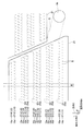
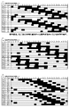
具体的な駆動信号と遅延時間の例を図9(a)〜(c)に示す。図はそれぞれ、16列の加圧室列に送る、40kHzの駆動周期の1周期分である25μs分の駆動信号である。着色した部分は、加圧室の体積を大きくするパルスが送られている時間帯を示している。駆動信号は、いずれもプレパルスの長さ(tc2−tc1)が1μs、プレパルスとメインパルスの間隔(tc3−tc2)が2.2μs、メインパルスの長さ(tc4−tc3)が6.2μs、メインパルスとキャンセルパルスの間隔(tc5−tc4)が2.4μs、キャンセルパルスの長さ(tc6−tc5)が1.6μsである。 Examples of specific drive signals and delay times are shown in FIGS. Each figure shows a drive signal for 25 μs, which is one cycle of a 40 kHz drive cycle, sent to 16 rows of pressurizing chambers. The colored portion indicates a time zone during which a pulse for increasing the volume of the pressurizing chamber is sent. In the drive signals, the pre-pulse length (tc2-tc1) is 1 μs, the interval between the pre-pulse and the main pulse (tc3-tc2) is 2.2 μs, the main pulse length (tc4-tc3) is 6.2 μs, main The interval between the pulse and the cancel pulse (tc5-tc4) is 2.4 μs, and the length of the cancel pulse (tc6-tc5) is 1.6 μs.
図9(a)〜(c)は、F1〜16の加圧室列に送られる駆動波形の例である。着色部は、駆動波形のうち、加圧室10の体積を減少させている信号の加わっていることを表している。つまり、図6(a)のt1〜t2、t3〜t4、t5〜t6に相当する時間が着色されている。
FIGS. 9A to 9C show examples of drive waveforms sent to the pressurization chamber rows F1 to F16. The colored portion represents that a signal for reducing the volume of the pressurizing
図9(a)で示した駆動方法では、遅延時間を加圧室列の端から順に、0、3、6、9、12、15、18、13、0、3、6、9、12、15、18、13μsにしている。このようにすることで、各駆動信号は、プレパルスの加圧室10の体積を減少させる信号(プレパルスのメインパルス側の電圧変化)とキャンセルパルスの加圧室10の体積を増加させる信号(キャンセルパルスのメインパルス側の電圧変化)との少なくとも一方が、隣接する加圧室10に送られる他のパルスに重なっている状態になるので、吐出ばらつきを少なくできる。
In the driving method shown in FIG. 9A, the delay times are set to 0, 3, 6, 9, 12, 15, 18, 13, 0, 3, 6, 9, 12, 15, 18, and 13 μs. In this way, each drive signal is a signal that decreases the volume of the pre-pulse pressurization chamber 10 (voltage change on the prepulse main pulse side) and a signal that increases the volume of the
図9(b)で示した駆動方法では、遅延時間を加圧室列の端から順に、4、0、8、4、12、8、16、12、20、16、24、20、3、24、7、3μsにしている。このようにすることで、各駆動信号は、プレパルスとキャンセルパルスのどちらか一方が隣接する加圧室10に送られるメインパルスに重なっている状態になるので、吐出ばらつきをより少なくできる。
In the driving method shown in FIG. 9B, the delay time is set to 4, 0, 8, 4, 12, 8, 16, 12, 20, 16, 24, 20, 3, 24, 7, and 3 μs. By doing so, each drive signal is in a state in which either the pre-pulse or the cancel pulse overlaps the main pulse sent to the adjacent pressurizing
図9(c)で示した駆動方法では、遅延時間を加圧室列の端から順に、0、5、6.8、8.6、10.6、12.6、14.6、10.2、0、5、6.8、8.6、10.6、12.6、14.6、10.2μsにしている。このようにすることで、各駆動信号は、プレパルスとキャンセルパルスのどちらか一方が隣接する加圧室10に送られるメインパルスに重なっている状態で、さらに、重なるメインパルスが1つになるので、吐出ばらつきをより少なくできる。
In the driving method shown in FIG. 9C, the delay times are set to 0, 5, 6.8, 8.6, 10.6, 12.6, 14.6, 14.6, 10. 2, 0, 5, 6.8, 8.6, 10.6, 12.6, 14.6, and 10.2 μs. By doing so, each drive signal is overlapped with the main pulse sent to the adjacent pressurizing
また、以上は圧力伝搬によるクロストークに着目して説明してきたが、さらに液体の供給について考慮して、遅延時間を調整するのが好ましい。駆動周波数が高くなると、単位時間当たりの吐出回数が増えるので、単位時間当たりの液体吐出総量が増える。吐出される液体は、マニホールド5を通じて加圧室10に供給されるが、液体吐出の総量が増えると、液体の供給が追い付かず、液体が吐出できなくなってしまうことがある。
Although the above has been described focusing on crosstalk due to pressure propagation, it is preferable to adjust the delay time in consideration of liquid supply. As the drive frequency increases, the number of ejections per unit time increases, so the total amount of liquid ejection per unit time increases. The liquid to be discharged is supplied to the pressurizing
駆動波形が送られことにより、本来、吐出されるべき時間当たりの液体吐出の総量が、時間当たりの供給可能量を上回ってしまうと、駆動波形を加えても吐出できない場合が生じ、全ての吐出を正常に行なうことはできなくなってしまう。さらに、時間当たりの液体吐出の総量が、時間当たりの供給可能量を、平均的には上回っていなくても、吐出ができなくなることがある。すなわち、マニホールド5内には、加圧室10に繋がる流路の開口が多数開いているが、これらに開口のうち、距離的に近接する開口が、時間的に近接してマニホールド5内の液体を吸い込もうとすると、局所的に液体が供給不足となり、吐出ができなくなることがある。
If the total amount of liquid discharge per hour that should be discharged exceeds the amount that can be supplied per hour due to the drive waveform being sent, it may not be possible to discharge even if the drive waveform is added. Cannot be performed normally. Furthermore, even if the total amount of liquid discharged per hour does not exceed the amount that can be supplied per hour on average, it may become impossible to discharge. That is, the
マニホールド5において、加圧室10から繋がる流路の開口が隣り合う加圧室10に対応する変位素子50に加える駆動信号をずらすことにより、このような局所的な供給不足を抑制できる。
By shifting the drive signal applied to the
マニホールド5から加圧室10に液体を引き込まれるのは、駆動信号のうち、加圧室10の体積を増加させる信号の後である。キャンセルパルスやプレパルスでは、体積を増加させる信号の後、すぐに体積を減少させる信号が続くので、マニホールド5から引き込まれる液体の量は少ない。これらと比較して、メインパルスは、引き込む液体の量が多いので、マニホールド5上で近接している開口に繋がっている加圧室10に対応する変位素子50に、メインパルスが時間的に近接して送られると供給不足になるおそれがある。
The liquid is drawn into the pressurizing
先に説明したように、隣り合っている加圧室10同士の間では、どちらかに送られる駆動信号に遅延が与えれる。マニホールド5に繋がっている加圧室列が、隣り合った2行の加圧室列である場合には、この遅延により、供給不足の発生を抑制できる。しかし、3行以上の加圧室列が繋がっている場合などは、間に一行の加圧室列を挟んで隣り合っている加圧室列がマニホールド5に繋がっていることになるので、それらの加圧室列に属する加圧室10から繋がっているがマニホールド5内の開口が近接している場合には、それらに送る駆動信号のタイミングを調整するのが好ましい。
As described above, between the pressurizing
メインパルスの加圧室10の体積を増加させる信号が加わると、加圧室10の体積は約AL/2の時間をかけて最大に達する。そのため、異なる加圧室列に属する加圧室10のうち、加圧室10から繋がっているマニホールド5内の開口間の距離がもっとも近い加圧室10に対応する変位素子50に、メインパルスを送る際に、メインパルスのうちの体積を増加させる信号を送るタイミングがAL/2以上ずれるように、それぞれの遅延時間を調節すれば、局所的な供給不足を抑制できる。すなわち、
When a signal for increasing the volume of the pressurizing
1・・・プリンタ
2・・・液体吐出ヘッド
4・・・流路部材
5・・・マニホールド(共通流路)
5a・・・副マニホールド
5b・・・開口
6・・・個別供給流路
8・・・吐出孔
9・・・加圧室群
10・・・加圧室
11a、b、c、d・・・加圧室列
12・・・しぼり
15a、b、c、d・・・吐出孔列
21・・・圧電アクチュエータ基板
21a・・・圧電セラミック層(振動板)
21b・・・圧電セラミック層
22〜31・・・プレート
32・・・個別流路
34・・・共通電極
35・・・個別電極
35a・・・個別電極本体
35b・・・引出電極
36・・・接続電極
50・・・変位素子DESCRIPTION OF
5a ... Sub-manifold 5b ...
21b ... Piezoelectric ceramic layer 22-31 ...
Claims (8)
前記加圧部に送られる駆動信号は、当該加圧部に対応する前記加圧室の体積を増加させた後、当該加圧室の体積を減少させて液体を吐出させるメインパルスと、該メインパルスを1つあるいは複数送る前に送られる、当該加圧室の体積を前記メインパルスよりも短い時間増加させた後、当該加圧室の体積を減少させて液体を吐出させないプレパルスと、前記メインパルスを1つあるいは複数送った後に送られる、当該加圧室の体積を前記メインパルスよりも短い時間増加させた後、当該加圧室の体積を減少させて液体を吐出させないキャンセルパルスとを含んでおり、
各々の前記加圧室列に対応する前記加圧部には同時に駆動信号が送られ始めるとともに、隣り合っている前記加圧室列間には遅延を与えて駆動信号が送られ、
各々の前記加圧部に送られる駆動信号は、
前記プレパルスの前記加圧室の体積を減少させる信号が、当該加圧室に対して前記行方向に隣り合っている前記加圧室に対応している前記加圧部に送られる前記メインパルスまたは前記キャンセルパルスが送られている間に送られるか、
前記キャンセルパルスの前記加圧室の体積を増加させる信号が、当該加圧室に対して前記行方向に隣り合っている前記加圧室に対応する前記加圧部に送られる前記メインパルスまたは前記プレパルスが送られている間に送られるか、
のうちの少なくとも一方であることを特徴とする液体吐出ヘッドの駆動方法。A plurality of discharge holes and a flow path member having a plurality of pressurization chambers connected to the plurality of discharge holes, respectively, and are stacked on the flow path member so as to cover the plurality of pressurization chambers, And a piezoelectric actuator substrate having a plurality of pressurizing sections that pressurize the liquid in the plurality of pressurizing chambers, respectively, and the flow path member includes a plurality of the pressurizing chambers arranged in a straight line. A plurality of pressurizing chamber columns, wherein the plurality of pressurizing chamber columns are arranged adjacent to each other in the row direction,
The drive signal sent to the pressurizing unit includes a main pulse for increasing the volume of the pressurizing chamber corresponding to the pressurizing unit and then decreasing the volume of the pressurizing chamber to discharge liquid, and the main pulse A pre-pulse which is sent before sending one or a plurality of pulses, increases the volume of the pressurizing chamber for a shorter time than the main pulse, and then decreases the volume of the pressurizing chamber so as not to discharge the liquid; A cancellation pulse that is sent after sending one or more pulses, and increases the volume of the pressurizing chamber for a shorter time than the main pulse, and then decreases the volume of the pressurizing chamber and does not discharge liquid. And
A driving signal is simultaneously sent to the pressurizing units corresponding to the respective pressurizing chamber rows, and a driving signal is sent with a delay between the adjacent pressurizing chamber rows,
The drive signal sent to each of the pressurizing units is
A signal for reducing the volume of the pressurizing chamber of the pre-pulse is sent to the pressurizing unit corresponding to the pressurizing chamber adjacent to the pressurizing chamber in the row direction, or Sent while the cancel pulse is being sent,
A signal for increasing the volume of the pressurizing chamber of the cancel pulse is sent to the pressurizing unit corresponding to the pressurizing chamber adjacent to the pressurizing chamber in the row direction, or the Sent while the prepulse is being sent,
A method for driving a liquid discharge head, wherein the method is at least one of the above.
前記プレパルスの前記加圧室の体積を減少させる信号が、当該加圧室に対して前記行方向に隣り合っている前記加圧室に対応している前記加圧部に送られる前記メインパルスまたは前記キャンセルパルスが送られている間に送られるか、
前記キャンセルパルスの前記加圧室の体積を増加させる信号が、当該加圧室に対して前記行方向に隣り合っている前記加圧室に対応する前記加圧部に送られる前記メインパルスまたは前記プレパルスが送られている間に送られるか、
のうちのいずれか一方であることを特徴とする請求項1記載の液体吐出ヘッドの駆動方法。The drive signal sent to each of the pressure units is
A signal for reducing the volume of the pressurizing chamber of the pre-pulse is sent to the pressurizing unit corresponding to the pressurizing chamber adjacent to the pressurizing chamber in the row direction, or Sent while the cancel pulse is being sent,
A signal for increasing the volume of the pressurizing chamber of the cancel pulse is sent to the pressurizing unit corresponding to the pressurizing chamber adjacent to the pressurizing chamber in the row direction, or the Sent while the prepulse is being sent,
The method of driving a liquid ejection head according to claim 1, wherein the driving method is any one of the above.
前記プレパルスの前記加圧室の体積を減少させる信号が、当該加圧室に対して前記行方向に隣り合っている前記加圧室に対応している前記加圧部に送られる前記メインパルスまたは前記キャンセルパルスが送られている間に送られる場合、前記プレパルスの全体が、前記メインパルスまたは前記キャンセルパルスが送られている間に送られ、
前記キャンセルパルスの前記加圧室の体積を増加させる信号が、当該加圧室に対して前記行方向に隣り合っている前記加圧室に対応する前記加圧部に送られる前記メインパルスまたは前記プレパルスが送られている間に送られる場合、前記キャンセルパルスの全体が前記メインパルスまたは前記プレパルスが送られている間に送られることを特徴とする請求項1または2に記載の液体吐出ヘッドの駆動方法。The drive signal sent to each of the pressure units is
A signal for reducing the volume of the pressurizing chamber of the pre-pulse is sent to the pressurizing unit corresponding to the pressurizing chamber adjacent to the pressurizing chamber in the row direction, or When sent while the cancel pulse is being sent, the entire pre-pulse is sent while the main pulse or the cancel pulse is being sent,
A signal for increasing the volume of the pressurizing chamber of the cancel pulse is sent to the pressurizing unit corresponding to the pressurizing chamber adjacent to the pressurizing chamber in the row direction, or the 3. The liquid discharge head according to claim 1, wherein when the pre-pulse is sent, the entire cancel pulse is sent while the main pulse or the pre-pulse is sent. 4. Driving method.
前記プレパルスの前記加圧室の体積を減少させる信号が、当該加圧室に対して前記行方向に隣り合っている前記加圧室に対応している前記加圧部に送られる前記メインパルスが送られている間に送られる場合、前記プレパルスの全体が、前記メインパルスが送られている間に送られ、
前記キャンセルパルスの前記加圧室の体積を増加させる信号が、当該加圧室に対して前記行方向に隣り合っている前記加圧室に対応する前記加圧部に送られる前記メインパルスが送られている間に送られる場合、前記キャンセルパルスの全体が前記メインパルスが送られている間に送られることを特徴とする請求項1または2に記載の液体吐出ヘッドの駆動方法。The drive signal sent to each of the pressure units is
The main pulse sent to the pressurization unit corresponding to the pressurization chamber adjacent to the pressurization chamber in the row direction is a signal for reducing the volume of the pressurization chamber of the prepulse. When sent while being sent, the whole of the pre-pulse is sent while the main pulse is being sent,
A signal for increasing the volume of the pressurizing chamber of the cancel pulse is sent to the pressurizing unit corresponding to the pressurizing chamber adjacent to the pressurizing chamber in the row direction. 3. The method of driving a liquid ejection head according to claim 1, wherein the cancel pulse is sent while the main pulse is being sent when the cancel pulse is sent.
前記加圧部に送られる駆動信号は、当該加圧部に対応する前記加圧室の体積を増加させた後、当該加圧室の体積を減少させて液体を吐出させるメインパルスと、該メインパルス1つあるいは複数送った後に送られる、当該加圧室の体積を前記メインパルスよりも短い時間増加させた後、当該加圧室の体積を減少させて液体を吐出させないキャンセルパルスとを含んでおり、
各々の前記加圧室列に対応する前記加圧部には同時に駆動信号が送られ始めるとともに、隣り合っている前記加圧室列間には遅延を与えて駆動信号が送られ、
各々の前記加圧部に送られる駆動信号は、
前記行方向に隣り合っている前記加圧室に対応する前記加圧部のうちの一方の前記加圧部に送られる、遅延が与えられていない駆動信号の前記キャンセルパルスが、他方の前記加圧部に送られる、遅延が与えられている駆動信号の前記メインパルスと前記キャンセルパルスとが送られる間、もしくは前記メインパルスを複数送る場合の前記メインパルスと前記メインパルスとが送られる間に送られるとともに、
遅延が与えられている駆動信号の前記キャンセルパルスが、遅延が与えられてない駆動信号の前記キャンセルパルスが送られ終った後に送られることを特徴とする液体吐出ヘッドの駆動方法。A plurality of discharge holes and a flow path member having a plurality of pressurization chambers connected to the plurality of discharge holes, respectively, and are stacked on the flow path member so as to cover the plurality of pressurization chambers, And a piezoelectric actuator substrate having a plurality of pressurizing sections that pressurize the liquid in the plurality of pressurizing chambers, respectively, and the flow path member includes a plurality of the pressurizing chambers arranged in a straight line. A plurality of pressurizing chamber columns, wherein the plurality of pressurizing chamber columns are arranged adjacent to each other in the row direction,
The drive signal sent to the pressurizing unit includes a main pulse for increasing the volume of the pressurizing chamber corresponding to the pressurizing unit and then decreasing the volume of the pressurizing chamber to discharge liquid, and the main pulse A cancel pulse that is sent after one or more pulses are sent, and the volume of the pressurizing chamber is increased for a shorter time than the main pulse, and then the volume of the pressurizing chamber is decreased and liquid is not discharged. And
A driving signal is simultaneously sent to the pressurizing units corresponding to the respective pressurizing chamber rows, and a driving signal is sent with a delay between the adjacent pressurizing chamber rows,
The drive signal sent to each of the pressurizing units is
The cancel pulse of the drive signal sent to one of the pressurizing units corresponding to the pressurizing chambers adjacent to the row direction without delay is applied to the other pressurizing unit. While the main pulse and the cancel pulse of the drive signal to which the delay is given are sent, or between the main pulse and the main pulse when a plurality of the main pulses are sent Sent,
A method of driving a liquid ejection head, wherein the cancel pulse of a drive signal to which a delay is given is sent after the cancel pulse of a drive signal to which a delay is not given is sent.
各々の前記開口に対して、
当該開口に繋がっている前記加圧室に対応する前記加圧部と、
当該開口に繋がっている前記加圧室の属する前記加圧室列と異なる前記加圧室列に属する前記加圧室に繋がっている前記開口のうちで、前記共通流路内における当該開口との距離がもっとも短い前記開口に繋がっている前記加圧室に対応する前記加圧部と
に送られる駆動信号が送られ始めるタイミングの差が、前記加圧室から前記吐出孔までを液体の圧力波が伝わる時間であるALの半分以上になるように遅延を与えられて送られることを特徴とする請求項1〜5のいずれかに記載の液体吐出ヘッドの駆動方法。The flow path member has a common flow path connected to the plurality of pressurization chambers, and the common flow path is provided with openings connected to the plurality of pressurization chambers.
For each said opening,
The pressurizing unit corresponding to the pressurizing chamber connected to the opening;
Of the openings connected to the pressurizing chamber belonging to the pressurizing chamber row different from the pressurizing chamber row belonging to the pressurizing chamber connected to the opening, the opening in the common flow path The difference in timing at which the drive signal sent to the pressurizing unit corresponding to the pressurization chamber connected to the opening having the shortest distance starts to be sent from the pressurization chamber to the discharge hole. 6. The method of driving a liquid ejection head according to claim 1, wherein the liquid ejection head is sent with a delay so as to be more than half of AL, which is a time during which the liquid is transmitted.
前記制御部の送る駆動信号は、前記加圧部に対応する前記加圧室の体積を増加させた後、当該加圧室の体積を減少させて液体を吐出させるメインパルスと、該メインパルスを1つあるいは複数送る前に送られる、当該加圧室の体積を前記メインパルスよりも短い時間増加させた後、当該加圧室の体積を減少させて液体を吐出させないプレパルスと、前記メインパルスを1つあるいは複数送った後に送られる、当該加圧室の体積を前記メインパルスよりも短い時間増加させた後、当該加圧室の体積を減少させて液体を吐出させないキャンセルパルスとを含んでおり、
各々の前記加圧室列に対応する前記加圧部には同時に駆動信号が送られ始めるとともに、隣り合っている前記加圧室列間には遅延を与えて駆動信号が送られ、
前記制御部が各々の前記加圧部に送る駆動信号は
前記プレパルスの前記加圧室の体積を減少させる信号が、当該加圧室に対して前記行方向に隣り合っている前記加圧室に対応している前記加圧部に送られる前記メインパルスまたは前記キャンセルパルスが送られている間に送られるか、
前記キャンセルパルスの前記加圧室の体積を増加させる信号が、当該加圧室に対して前記行方向に隣り合っている前記加圧室に対応する前記加圧部に送られる前記メインパルスまたは前記プレパルスが送られている間に送られるか、
のうちの少なくとも一方であることを特徴とする記録装置。A plurality of discharge holes and a flow path member having a plurality of pressurization chambers connected to the plurality of discharge holes, respectively, and are stacked on the flow path member so as to cover the plurality of pressurization chambers, And a piezoelectric actuator substrate having a plurality of pressurizing sections that pressurize the liquid in the plurality of pressurizing chambers, respectively, and the flow path member includes a plurality of the pressurizing chambers arranged in a straight line. A plurality of pressurizing chamber rows, the liquid ejecting head in which the plurality of pressurizing chamber rows are arranged adjacent to each other in a row direction, a transport unit that transports a recording medium to the liquid ejecting head, and the liquid A recording apparatus comprising a control unit for controlling the ejection head,
The drive signal sent by the control unit includes a main pulse for increasing the volume of the pressurizing chamber corresponding to the pressurizing unit and then discharging the liquid by decreasing the volume of the pressurizing chamber, and the main pulse. A pre-pulse that is sent before one or a plurality of times and increases the volume of the pressurizing chamber for a shorter time than the main pulse, and then decreases the volume of the pressurizing chamber and does not discharge the liquid; And a cancel pulse that is sent after one or a plurality of feeds, increases the volume of the pressurizing chamber for a shorter time than the main pulse, and then decreases the volume of the pressurizing chamber and does not discharge liquid. ,
A driving signal is simultaneously sent to the pressurizing units corresponding to the respective pressurizing chamber rows, and a driving signal is sent with a delay between the adjacent pressurizing chamber rows,
The drive signal that the control unit sends to each pressurizing unit is a signal that reduces the volume of the pressurizing chamber of the pre-pulse to the pressurizing chamber that is adjacent to the pressurizing chamber in the row direction. Sent while the main pulse or the cancel pulse sent to the corresponding pressurizing unit is being sent,
A signal for increasing the volume of the pressurizing chamber of the cancel pulse is sent to the pressurizing unit corresponding to the pressurizing chamber adjacent to the pressurizing chamber in the row direction, or the Sent while the prepulse is being sent,
A recording apparatus characterized by being at least one of the above.
前記制御部の送る駆動信号は、前記加圧部に対応する前記加圧室の体積を増加させた後、当該加圧室の体積を減少させて液体を吐出させるメインパルスと、該メインパルスを1つあるいは複数送った後に送られる、当該加圧室の体積を前記メインパルスよりも短い時間増加させた後、当該加圧室の体積を減少させて液体を吐出させないキャンセルパルスとを含んでおり、
各々の前記加圧室列に対応する前記加圧部には同時に駆動信号が送られ始めるとともに、隣り合っている前記加圧室列間には遅延を与えて駆動信号が送られ、
前記制御部が各々の前記加圧部に送る駆動信号は
前記行方向に隣り合っている前記加圧室に対応する前記加圧部のうちの一方の前記加圧部に送られる、遅延が与えられていない駆動信号の前記キャンセルパルスが、他方の前記加圧部に送られる、遅延が与えられている駆動信号の前記メインパルスと前記キャンセルパルスとが送られる間、もしくは前記メインパルスを複数送る場合の前記メインパルスと前記メインパルスとが送られる間に送られるとともに、
遅延が与えられている駆動信号の前記キャンセルパルスが、遅延が与えられてない駆動信号の前記キャンセルパルスが送られ終った後に送られることを特徴とする記録装置。
A plurality of discharge holes and a flow path member having a plurality of pressurization chambers connected to the plurality of discharge holes, respectively, and are stacked on the flow path member so as to cover the plurality of pressurization chambers, And a piezoelectric actuator substrate having a plurality of pressurizing sections that pressurize the liquid in the plurality of pressurizing chambers, respectively, and the flow path member includes a plurality of the pressurizing chambers arranged in a straight line. A plurality of pressurizing chamber rows, the liquid ejecting head in which the plurality of pressurizing chamber rows are arranged adjacent to each other in a row direction, a transport unit that transports a recording medium to the liquid ejecting head, and the liquid A recording apparatus comprising a control unit for controlling the ejection head,
The drive signal sent by the control unit includes a main pulse for increasing the volume of the pressurizing chamber corresponding to the pressurizing unit and then discharging the liquid by decreasing the volume of the pressurizing chamber, and the main pulse. And a cancel pulse that is sent after one or a plurality of feeds, increases the volume of the pressurizing chamber for a shorter time than the main pulse, and then decreases the volume of the pressurizing chamber and does not discharge liquid. ,
A driving signal is simultaneously sent to the pressurizing units corresponding to the respective pressurizing chamber rows, and a driving signal is sent with a delay between the adjacent pressurizing chamber rows,
The drive signal sent by the control unit to each of the pressurizing units is sent to the pressurizing unit of one of the pressurizing units corresponding to the pressurizing chambers adjacent to each other in the row direction. The cancel pulse of the drive signal that has not been sent is sent to the other pressurizing unit, while the main pulse and the cancel pulse of the drive signal to which the delay is given is sent, or a plurality of the main pulses are sent And when the main pulse and the main pulse of the case are sent,
The recording apparatus, wherein the cancel pulse of the drive signal to which the delay is given is sent after the cancel pulse of the drive signal to which the delay is not given is sent.
Priority Applications (1)
| Application Number | Priority Date | Filing Date | Title |
|---|---|---|---|
| JP2014507587A JP5806387B2 (en) | 2012-03-27 | 2013-02-28 | Method for driving liquid ejection head and recording apparatus |
Applications Claiming Priority (4)
| Application Number | Priority Date | Filing Date | Title |
|---|---|---|---|
| JP2012071540 | 2012-03-27 | ||
| JP2012071540 | 2012-03-27 | ||
| JP2014507587A JP5806387B2 (en) | 2012-03-27 | 2013-02-28 | Method for driving liquid ejection head and recording apparatus |
| PCT/JP2013/055595 WO2013146092A1 (en) | 2012-03-27 | 2013-02-28 | Method for driving liquid-discharging head and recording device |
Publications (2)
| Publication Number | Publication Date |
|---|---|
| JP5806387B2 true JP5806387B2 (en) | 2015-11-10 |
| JPWO2013146092A1 JPWO2013146092A1 (en) | 2015-12-10 |
Family
ID=49259367
Family Applications (1)
| Application Number | Title | Priority Date | Filing Date |
|---|---|---|---|
| JP2014507587A Active JP5806387B2 (en) | 2012-03-27 | 2013-02-28 | Method for driving liquid ejection head and recording apparatus |
Country Status (5)
| Country | Link |
|---|---|
| US (1) | US9061490B2 (en) |
| EP (1) | EP2832544B1 (en) |
| JP (1) | JP5806387B2 (en) |
| CN (1) | CN104144789B (en) |
| WO (1) | WO2013146092A1 (en) |
Family Cites Families (15)
| Publication number | Priority date | Publication date | Assignee | Title |
|---|---|---|---|---|
| JP4075317B2 (en) * | 2001-04-11 | 2008-04-16 | 富士ゼロックス株式会社 | Inkjet recording head and inkjet recording apparatus |
| JP3920596B2 (en) * | 2001-06-25 | 2007-05-30 | 東芝テック株式会社 | Inkjet recording apparatus and inkjet recording method |
| JP2003305852A (en) | 2002-02-18 | 2003-10-28 | Brother Ind Ltd | Ink jet head and ink jet printer having the same |
| CN100579779C (en) * | 2004-03-31 | 2010-01-13 | 京瓷株式会社 | liquid ejection device |
| JP4543847B2 (en) * | 2004-09-14 | 2010-09-15 | ブラザー工業株式会社 | Line-type inkjet printer |
| JP2006110857A (en) * | 2004-10-14 | 2006-04-27 | Brother Ind Ltd | Ink droplet ejection device |
| JP2006123397A (en) * | 2004-10-29 | 2006-05-18 | Brother Ind Ltd | Line type ink jet recording apparatus and ink jet recording apparatus |
| US7604313B2 (en) * | 2005-04-26 | 2009-10-20 | Brother Kogyo Kabushiki Kaisha | Ink-droplet ejecting apparatus |
| JP2007190901A (en) * | 2005-04-26 | 2007-08-02 | Brother Ind Ltd | Ink droplet ejection device |
| JP2007015127A (en) * | 2005-07-05 | 2007-01-25 | Seiko Epson Corp | Liquid ejector |
| JP4687442B2 (en) * | 2005-12-21 | 2011-05-25 | セイコーエプソン株式会社 | Liquid ejector |
| JP5034582B2 (en) * | 2007-03-16 | 2012-09-26 | ブラザー工業株式会社 | Droplet ejector |
| JP4569657B2 (en) * | 2008-03-31 | 2010-10-27 | ブラザー工業株式会社 | Droplet ejection apparatus and droplet ejection control program |
| JP5309808B2 (en) * | 2008-09-04 | 2013-10-09 | セイコーエプソン株式会社 | Liquid ejecting apparatus and method for controlling liquid ejecting apparatus |
| JP5598113B2 (en) * | 2010-06-21 | 2014-10-01 | ブラザー工業株式会社 | Liquid ejection device, control device, and program |
-
2013
- 2013-02-28 EP EP13770050.6A patent/EP2832544B1/en active Active
- 2013-02-28 JP JP2014507587A patent/JP5806387B2/en active Active
- 2013-02-28 WO PCT/JP2013/055595 patent/WO2013146092A1/en not_active Ceased
- 2013-02-28 CN CN201380012224.8A patent/CN104144789B/en active Active
- 2013-02-28 US US14/389,202 patent/US9061490B2/en active Active
Also Published As
| Publication number | Publication date |
|---|---|
| CN104144789B (en) | 2016-02-03 |
| US20150042707A1 (en) | 2015-02-12 |
| EP2832544B1 (en) | 2020-11-18 |
| EP2832544A4 (en) | 2017-03-01 |
| EP2832544A1 (en) | 2015-02-04 |
| CN104144789A (en) | 2014-11-12 |
| WO2013146092A1 (en) | 2013-10-03 |
| JPWO2013146092A1 (en) | 2015-12-10 |
| US9061490B2 (en) | 2015-06-23 |
Similar Documents
| Publication | Publication Date | Title |
|---|---|---|
| JP4977803B2 (en) | Liquid discharge head and recording apparatus using the same | |
| JP5869295B2 (en) | Liquid ejection head device, recording device using the same, and printing method | |
| JP6114058B2 (en) | Flow path member for liquid discharge head, liquid discharge head using the same, and recording apparatus | |
| JP4935418B2 (en) | Inkjet recording device | |
| CN100443304C (en) | Droplet ejection device and driving method thereof | |
| JP5932490B2 (en) | Liquid discharge head and recording apparatus using the same | |
| JP2006150816A (en) | Inkjet recording apparatus and waveform determination method | |
| JP5183547B2 (en) | Recording device | |
| JP2012116040A (en) | Recording device | |
| JP2012071594A (en) | Liquid ejection head and recorder using the same | |
| JP5687002B2 (en) | Method for driving liquid ejection head and recording apparatus | |
| JP5806387B2 (en) | Method for driving liquid ejection head and recording apparatus | |
| JP5829513B2 (en) | Liquid ejecting apparatus and recording apparatus using the same | |
| JP4588618B2 (en) | Inkjet recording device | |
| EP4011627B1 (en) | Inkjet head | |
| JP6034887B2 (en) | Liquid discharge head and recording apparatus using the same | |
| JP2012116039A (en) | Liquid discharge head, and recording device using the same | |
| JP5473559B2 (en) | Method for driving liquid ejection head and recording apparatus | |
| JP2012045889A (en) | Liquid ejection head and recording device using the same | |
| JP5832276B2 (en) | Liquid ejecting apparatus and recording apparatus using the same | |
| JP6134030B2 (en) | Liquid discharge head and recording apparatus using the same | |
| JP2012096385A (en) | Liquid ejection head, and recording apparatus using the same | |
| JP2011194886A (en) | Liquid ejection head and recorder using the same | |
| JP2014008684A (en) | Printing method and recording apparatus | |
| JP2010228144A (en) | Liquid discharge head, recording apparatus using the same, and method of using liquid discharge head |
Legal Events
| Date | Code | Title | Description |
|---|---|---|---|
| TRDD | Decision of grant or rejection written | ||
| A01 | Written decision to grant a patent or to grant a registration (utility model) |
Free format text: JAPANESE INTERMEDIATE CODE: A01 Effective date: 20150806 |
|
| A61 | First payment of annual fees (during grant procedure) |
Free format text: JAPANESE INTERMEDIATE CODE: A61 Effective date: 20150903 |
|
| R150 | Certificate of patent or registration of utility model |
Ref document number: 5806387 Country of ref document: JP Free format text: JAPANESE INTERMEDIATE CODE: R150 |