JP5805624B2 - Multiple screw - Google Patents
Multiple screw Download PDFInfo
- Publication number
- JP5805624B2 JP5805624B2 JP2012507429A JP2012507429A JP5805624B2 JP 5805624 B2 JP5805624 B2 JP 5805624B2 JP 2012507429 A JP2012507429 A JP 2012507429A JP 2012507429 A JP2012507429 A JP 2012507429A JP 5805624 B2 JP5805624 B2 JP 5805624B2
- Authority
- JP
- Japan
- Prior art keywords
- head
- longitudinal axis
- bone
- openings
- opening
- Prior art date
- Legal status (The legal status is an assumption and is not a legal conclusion. Google has not performed a legal analysis and makes no representation as to the accuracy of the status listed.)
- Expired - Fee Related
Links
Images


Classifications
-
- A—HUMAN NECESSITIES
- A61—MEDICAL OR VETERINARY SCIENCE; HYGIENE
- A61B—DIAGNOSIS; SURGERY; IDENTIFICATION
- A61B17/00—Surgical instruments, devices or methods, e.g. tourniquets
- A61B17/56—Surgical instruments or methods for treatment of bones or joints; Devices specially adapted therefor
- A61B17/58—Surgical instruments or methods for treatment of bones or joints; Devices specially adapted therefor for osteosynthesis, e.g. bone plates, screws, setting implements or the like
- A61B17/68—Internal fixation devices, including fasteners and spinal fixators, even if a part thereof projects from the skin
- A61B17/84—Fasteners therefor or fasteners being internal fixation devices
- A61B17/86—Pins or screws or threaded wires; nuts therefor
- A61B17/8605—Heads, i.e. proximal ends projecting from bone
-
- A—HUMAN NECESSITIES
- A61—MEDICAL OR VETERINARY SCIENCE; HYGIENE
- A61B—DIAGNOSIS; SURGERY; IDENTIFICATION
- A61B17/00—Surgical instruments, devices or methods, e.g. tourniquets
- A61B17/56—Surgical instruments or methods for treatment of bones or joints; Devices specially adapted therefor
- A61B17/58—Surgical instruments or methods for treatment of bones or joints; Devices specially adapted therefor for osteosynthesis, e.g. bone plates, screws, setting implements or the like
- A61B17/68—Internal fixation devices, including fasteners and spinal fixators, even if a part thereof projects from the skin
- A61B17/74—Devices for the head or neck or trochanter of the femur
- A61B17/742—Devices for the head or neck or trochanter of the femur having one or more longitudinal elements oriented along or parallel to the axis of the neck
- A61B17/744—Devices for the head or neck or trochanter of the femur having one or more longitudinal elements oriented along or parallel to the axis of the neck the longitudinal elements coupled to an intramedullary nail
-
- A—HUMAN NECESSITIES
- A61—MEDICAL OR VETERINARY SCIENCE; HYGIENE
- A61B—DIAGNOSIS; SURGERY; IDENTIFICATION
- A61B17/00—Surgical instruments, devices or methods, e.g. tourniquets
- A61B17/56—Surgical instruments or methods for treatment of bones or joints; Devices specially adapted therefor
- A61B17/58—Surgical instruments or methods for treatment of bones or joints; Devices specially adapted therefor for osteosynthesis, e.g. bone plates, screws, setting implements or the like
- A61B17/68—Internal fixation devices, including fasteners and spinal fixators, even if a part thereof projects from the skin
- A61B17/74—Devices for the head or neck or trochanter of the femur
- A61B17/742—Devices for the head or neck or trochanter of the femur having one or more longitudinal elements oriented along or parallel to the axis of the neck
- A61B17/746—Devices for the head or neck or trochanter of the femur having one or more longitudinal elements oriented along or parallel to the axis of the neck the longitudinal elements coupled to a plate opposite the femoral head
-
- A—HUMAN NECESSITIES
- A61—MEDICAL OR VETERINARY SCIENCE; HYGIENE
- A61B—DIAGNOSIS; SURGERY; IDENTIFICATION
- A61B17/00—Surgical instruments, devices or methods, e.g. tourniquets
- A61B17/56—Surgical instruments or methods for treatment of bones or joints; Devices specially adapted therefor
- A61B17/58—Surgical instruments or methods for treatment of bones or joints; Devices specially adapted therefor for osteosynthesis, e.g. bone plates, screws, setting implements or the like
- A61B17/68—Internal fixation devices, including fasteners and spinal fixators, even if a part thereof projects from the skin
- A61B17/80—Cortical plates, i.e. bone plates; Instruments for holding or positioning cortical plates, or for compressing bones attached to cortical plates
- A61B17/8052—Cortical plates, i.e. bone plates; Instruments for holding or positioning cortical plates, or for compressing bones attached to cortical plates immobilised relative to screws by interlocking form of the heads and plate holes, e.g. conical or threaded
- A61B17/8057—Cortical plates, i.e. bone plates; Instruments for holding or positioning cortical plates, or for compressing bones attached to cortical plates immobilised relative to screws by interlocking form of the heads and plate holes, e.g. conical or threaded the interlocking form comprising a thread
Description
〔優先権主張〕
本出願は、2009年4月24日出願の「Multiplexed Screws」と題する米国特許仮出願第61/172,451号の優先権を主張するものであり、当該出願の全開示内容を、参照により本明細書に援用する。
[Priority claim]
This application claims priority from US Provisional Application No. 61 / 172,451 entitled “Multiplexed Screws” filed Apr. 24, 2009, the entire disclosure of which is incorporated herein by reference. This is incorporated into the description.
本発明は、骨折の処置のための器具に関し、具体的には、限られたスペース内において、様々な骨固定要素で骨折を固定することを可能とする、複数の開口を含むスクリューのような、骨接合用インプラントに関する。 The present invention relates to an instrument for the treatment of fractures, in particular, such as a screw comprising a plurality of openings, which allows the fracture to be fixed with various bone anchoring elements in a limited space. The present invention relates to an osteosynthesis implant.
骨折は、プレート、ネイル、スクリューのような器具を用いて固定されうる。現在、例えばロッキングヘッドスクリュー、可変角スクリュー、ピンおよびブレードのような、種々の異なる骨固定要素が利用可能である。しかしながら、プレートおよびネイルは、一般に、特定の型の骨固定要素との係合に限定されている。加えて、特定の状況においては、骨片の固定および再配置のために僅かなスペースしか利用することができず、そのために、このような骨折の固定に適する手法が限定される。 Fractures can be fixed using instruments such as plates, nails and screws. Currently, a variety of different bone anchoring elements are available, such as rocking head screws, variable angle screws, pins and blades. However, plates and nails are generally limited to engagement with certain types of bone anchoring elements. In addition, in certain situations, little space is available for bone fragment fixation and repositioning, which limits the techniques suitable for such fracture fixation.
本発明は、骨固定要素を対象としており、この骨固定要素は、周囲に分布された複数の固定要素開口を含む頭部と結合する、固定要素の長手軸にほぼ沿って延在するシャフトを含み、固定要素開口の各々は、頭部を通って、頭部の近位面から頭部の遠位面まで延在し、固定要素開口の各々は、頭部を通って、開口軸にそって延在する。 The present invention is directed to a bone anchoring element that includes a shaft extending generally along a longitudinal axis of the anchoring element that couples to a head including a plurality of anchoring element openings distributed around the bone anchoring element. Each of the fixation element openings extends through the head from the proximal face of the head to the distal face of the head, and each of the fixation element openings passes along the opening axis through the head. Extend.
本発明は、以下の説明および添付の図面を参照することで更に理解されうるものであり、ここで、類似の要素は同一の参照番号によって参照される。本発明は、骨折の処置のための器具に関し、具体的には、スクリューのような骨接合用インプラントに関する。本発明の例示的実施形態は、限られたスペース内において、様々な骨固定要素で骨折を固定することを可能とする、複数の開口を含む多重スクリューを提供する。本明細書で用いる近位および遠位の用語は、任意の特定の方向に言及するために用いられるものではなく、外科医または他の本器具の使用者に向かう方向(近位)および離れる方向(遠位)を記述するために用いられるものであることに留意すべきである。 The present invention may be further understood with reference to the following description and the appended drawings, wherein like elements are referred to with the same reference numerals. The present invention relates to a device for the treatment of fractures, and in particular to an osteosynthesis implant such as a screw. Exemplary embodiments of the present invention provide a multiple screw that includes a plurality of apertures that allow a fracture to be fixed with various bone fixation elements within a limited space. As used herein, the terms proximal and distal are not used to refer to any particular direction, but to a surgeon or other user of the instrument (proximal) and away ( Note that it is used to describe (distal).
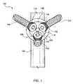
図1〜図11に示すように、システム100は、骨折を固定するために、複数の骨固定要素106がそこを通して挿入され得る、インプラント104内に挿入可能な多重スクリュー102を含む。インプラント104は、例えば骨プレート、ネイル等のような、任意の骨接合用インプラントでありうる。しかしながら、インプラント104は、多重スクリュー102も同様に骨内に直接挿入されうるということを要求されうるものではないことが、当業者に理解されるであろう。多重スクリュー102は、種々の異なる種類の骨折、特に、スクリューが占めうるスペースが限定されているような骨折を固定するために用いられうることもまた、当業者に理解されるであろう。
As shown in FIGS. 1-11, the
図3〜図5に示すように、多重スクリュー102は、頭部108および頭部から遠位に延在する本体部110を含む。好適な実施形態において、頭部108および本体部110は一体に形成される。頭部108は、手術部位において骨内に挿入される時、骨から離れた方向に面する近位面112と、手術部位において、骨と面する遠位面114とを含む。また、頭部108は、頭部108の周囲に分布し、各々がその中に骨固定要素106を収容できるようなサイズおよび形状とされている、複数の開口116を含む。
As shown in FIGS. 3-5, the
第1の例示的な実施形態において、図1〜図9に示すように、近位面112は実質的に凹状でありうる一方で、遠位面114は実質的に凸状でありうる。開口116の各々は、頭部108を通って、近位面112から遠位面114まで、近位面112に対してほぼ垂直に延在し、開口116は、近位面112の近位の点において、多重スクリュー102の長手軸Lに対して最大70°の角度で、開口116の各々の中心軸Cが長手軸Lと交差するように配向されている。代替の実施形態においては、図10に示すように、近位面112は実質的に凸状、および/または遠位面114は実質的に凹状でありうるものであり、遠位面114の遠位の点において、長手軸Lに対して最大−45°の角度で、開口116の各々の中心軸Cが長手軸Lと交差する。別の代替の実施形態においては、図11に示すように、開口116の中心軸Cは、近位面112の近位の点または遠位面114の遠位の点のいずれにおいても、長手軸Lと関与しない。むしろ、中心軸Cは、中心軸Cが長手軸Lとほぼ平行であるように、同様に頭部108を通って延在しうる。加えて、近位面112および/または遠位面114は実質的に平面でありうる。
In the first exemplary embodiment, as shown in FIGS. 1-9, the
当業者には理解されるであろうが、複数の中心軸Cと長手軸Lの間の交点の角度は、互いに等しいものであるか、または特定の適用の要件に応じて、異なるものでありうる。具体的には、これらの角度は、スクリュー102を介して骨内に挿入される複数の骨固定要素が、所望の程度で長手軸L(および本体部110)から離れて広がるようにして、それによって、骨固定要素によって固定される骨の領域を増大させるように選択される。頭部108のサイズを縮小するため、開口116は、頭部108によって部分的にのみ囲まれうる。すなわち、開口116の各々の近位部は、開放された状態でありうる。したがって、図12〜図14に示すように、各々の開口は、180°以上から360°(この場合、開口116は完全に囲まれる)までの範囲で囲まれうる。好適な実施形態において、開口116は、およそ240°〜270°の範囲で囲まれうる。
As will be appreciated by those skilled in the art, the angles of intersection between the plurality of central axes C and longitudinal axes L are equal to each other or may vary depending on the requirements of a particular application. sell. Specifically, these angles are such that a plurality of bone anchoring elements inserted into the bone via the
1つまたは複数の開口116は、そこを通って挿入される骨固定要素106のロッキングヘッド上の対応するねじ切りと係合するための、開口116の内部表面120に沿ったねじ切り122を含みうる。ねじ切り122は、例えば、そこを通って挿入される骨固定要素のロッキングヘッドのねじ切りの経路に対応する螺旋経路に沿って形成されうる。好適な実施形態において頭部108は3つの開口116を含みうるが、頭部108は任意の数の開口116を含みうることが、当業者によって理解されるであろう。
The one or
好適な実施形態において、最小のスペース内で、複数の骨固定要素106が頭部108を通って挿入されることを可能としうるように、頭部108はほぼ円形でありうる。好適な実施形態において、頭部108は、40mm未満の直径を有しうる。しかしながら、頭部108のサイズは、例えば、開口116の数、開口116に収容される骨固定要素106のサイズ、および長手軸Lに対する中心軸Cの角度のような、多数の要因に応じて変化しうることが、当業者によって理解されるであろう。頭部108は、様々な形状およびサイズを取りうることもまた、当業者によって理解されるであろう。また、頭部108は、近位面112上の、駆動工具と接合するためのサイズおよび形状とされた接合要素124を含みうる。好適な実施形態において、接合要素124は、駆動工具の六角形状部と接合可能な、六角形状の凹部でありうる。しかしながら、接合要素124は、多重スクリュー102がインプラント104内に挿入される際に、長手軸について回転しうるように、駆動工具と接合可能な任意の凹部または突起部でありうることが、当業者によって理解されるであろう。
In a preferred embodiment, the
本体部110は、近位端126から遠位端128まで長手方向に延在しうるものであり、近位端126は、頭部108の遠位面114に取り付けられる。本体部110は、インプラント104と係合するために、少なくともその長さの一部に沿ったねじ切り130を含みうる。インプラント104を骨に対して固定するために、多重スクリュー102は、インプラント104の開口140を通して挿入可能であることが、当業者によって理解されるであろう。したがって、本体部110は、インプラント104の開口140を通して挿入可能なサイズおよび形状とされる。また、多重スクリュー102は、例えば鋼鉄、チタン、およびPEEKのような、様々な生体適合性の材料で形成されうることも、当業者によって理解されるであろう。
The
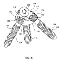
複数の骨固定要素106は、例えばロッキングヘッドスクリューのような、任意の種類の骨固定要素を含みうる。図6〜図9に示すように、複数の骨固定要素の各々は、頭部132およびそこから延在するシャフト134を含みうる。頭部132が任意の複数の開口116のねじ切り122と係合しうるように、頭部132は、その周囲にねじ切り136または他の係合機構を含みうる。シャフト134もまた、骨と係合するために、少なくともその長さの一部に沿ったねじ切り138を含みうる。骨固定要素106の各々は、開口116の各々の中心軸Cに沿って挿入可能である。中心軸Cと長手軸Lの交点の角度によって、骨固定要素106のシャフト134は、図6〜図9に示すように、骨内に更に挿入されるにつれて(すなわち、多重スクリュー102の遠位面114の遠位で)、長手軸Lに対して外側に広がるか、図10に示すように、長手軸Lに対して内側に向かうか、または図11〜図12に示すように、長手軸Lに対して平行となる。複数の骨固定要素106は、小さなスペースを通じて、単一の骨固定要素のシャフトによって固定されるであろう領域よりも広い骨の領域を固定することが可能であることが、当業者によって理解されるであろう。図1〜図3に示すように、骨固定要素106の各々は、骨またはインプラント104の別の開口142のいずれかと係合するための1つまたは複数の開口116を通して挿入可能であることもまた、当業者によって理解されるであろう。
The plurality of
システム100の例示的な外科的用途によれば、図13〜図14に示すように、スクリュー102は、例えば大腿骨頚部骨折の処置の為の髄内釘のようなインプラント104と共に用いられうる。(完全に囲まれた複数の開口116と共に示す)スクリュー102の本体部110は、頭部108が骨の外部表面と隣接するまで、骨の中に、髄内釘104内の穴105を通して挿入されうる。その後、骨固定要素106が、開口116を通して挿入されうる。示す実施形態において、更なる固定および安定性を提供するために、骨固定要素106が髄内釘104の両側に沿って延在するように、骨固定要素106は、スクリュー102の長手軸Lに対して外側に広がる。髄内釘104を骨に対して固定するために、追加の固定要素が髄内釘104の他の穴を通して挿入されうることが、当業者によって理解されるであろう。
According to an exemplary surgical application of the
第2の例示的実施形態において、図15に示すように、システム200は、そこを通して複数の骨固定要素206を受容するように適合および構成された多重スクリュー202を含む。多重スクリュー102と同様に、多重スクリュー202は、頭部208と、本体部210とを含む。しかしながら、頭部208と本体部210が互いに対して可動であるように、頭部208と本体部210は2部品アセンブリを形成する。具体的には、この実施形態における頭部208と本体部210は、その長手軸Lについて、互いに対して回転可能である。
In a second exemplary embodiment, as shown in FIG. 15, the
頭部208は、頭部108と実質的に類似でありうるものであり、開口116に類似する開口216を含むが、そこを通って延在し、スクリュー202の本体部210の近位端258を収容する中央開口250の第1の部分252を有する一方で、第2の部分254は、近位端258を本体部210の遠位部260と接続する縮小径部262を収容する、中央開口250を更に含む。第1の部分252は、直径において第2の部分254よりも大きいので、拡大径近位端258はそこから遠位に通過することができない。第2の部分254は、本体部210が頭部208内に組み込まれる際に、対応する遠位部260上のねじ切り264と係合するためのねじ切り256を含む。当業者には理解されるであろうが、近位端258は、駆動工具と係合するための、その近位端における駆動要素224を更に含みうる。遠位部260のねじ切り264が中央開口250のねじ切り256から係脱され、第2の部分254が縮小径部262を受容するまで、本体部210は、駆動要素224を介して、開口250を通って遠位に動かされうる。したがって、中央開口250のねじ切り256の遠位端は、ねじ切り264の近位端を包囲して、本体部210が頭部208内部で回転することを可能とし、また、本体部210が不注意によりそこから除去されてしまうことを防止する。
The
システム200は、システム100に関して先に説明したものとほぼ同様の様式で用いられうることが、当業者によって理解されるであろう。具体的には、多重スクリュー202の頭部208内部に本体部210が永続的に搭載されると、多重スクリュー202は、駆動要素224を介して、インプラントの開口および/または骨の中へと動かされうる。その後、所望の通りに骨を固定するために、骨固定要素206が、開口216の各々の中心軸に沿って挿入されうる。
It will be appreciated by those skilled in the art that
図16〜図18に示すように、第3の例示的実施形態によるシステム300は、先に説明したシステム100と実質的に類似であり、スクリュー102と実質的に類似のスクリュー302を備える。スクリュー302は、頭部308と、そこから遠位に延在し、目標の骨304内に挿入可能な本体部310と、を有する。本体部310は、少なくともその長さの一部に沿って延在するねじ切り330を含み、頭部308は、そこを通ってその近位面312から遠位面314まで延在する、複数の第1の型の開口316を含む。開口316は、開口116と実質的に類似する。第1の型の開口316は、第1の型の骨固定要素306を受容するように構成され、第1の型の骨固定要素306は、そこを通して挿入され、回転安定性を与え、および/または付加的な曲げ強度を与える。頭部308は、スクリュー302を骨に係止する、第2の型の骨スクリュー372を受容するための、頭部308を通って近位面312から遠位面314まで延在する、少なくとも1つの第2の型の開口370を更に含む。好適な実施形態において、スクリュー302は、3つの第2の型の開口370を含む。
As shown in FIGS. 16-18, a
好適な実施形態において、第1の型の開口316の各々は、第1の型の骨固定要素306が、開口316を通ってスクリュー302の本体部310とほぼ平行に延在するように、スクリュー302の長手軸L´とほぼ平行に中心軸C´を画定する。しかしながら、システム100に関して先に検討したとおり、第1の型の骨固定要素306が、長手軸L´に対して、それぞれ外側または内側に広がるように、中心軸C´もまた、近位面312の近位で、または遠位面314の遠位で、長手軸L´と交差しうることが、当業者によって理解されるであろう。
In a preferred embodiment, each of the first type of
第2の型の開口370の各々は、近位面312の近位で長手軸L´と交差する中心軸Sを有する。好適な実施形態において、中心軸Sは、およそ30°の角度で長手軸L´と交差する。しかしながら、この交角は、特定の適用の要件に応じて変化しうることが、当業者によって理解されるであろう。第2の型の骨固定要素370は、完全に囲まれうるものであり、その内部表面に沿って、第2の型の骨固定要素372の頭部(図示せず)に沿った対応するねじ切りを収容するための、ねじ切り374を含みうる。第2の型の骨固定要素372は、第1の型の骨固定要素306が第1の型の開口316を通して挿入された後に、スクリュー302を骨に係止するため、およびスクリュー302が骨から後退するのを防止するために、第2の型の開口370を通して挿入されうる。スクリュー302は、種々のサイズおよび/または型の骨固定要素を収容するために、異なる角度で頭部308を通って延在する、更なる型の開口を含みうることが、当業者によって理解されるであろう。頭部308はまた、ガイドワイヤを収容するための更なる開口も含みうる。スクリュー302は、互いに等しいか、または特定の適用の要件に応じて異なる、中心軸Sおよび長手軸L´の間の交点を有する、2以上の第2の型の開口370を含みうることもまた、当業者によって理解されるであろう。
Each of the
図18に示すように、システム300は、例えば大腿骨等の、骨の頚部における骨折を固定するために用いられうる。システム300の例示的な外科的手法によれば、骨の骨折部分を一時的に整列させるために、k−ワイヤが骨内に挿入されうる。所望のスクリュー302の位置に対応するために、追加的なk−ワイヤが骨内に配置されうる。その後、そこを通して穴を開けるために、ドリルが追加的k−ワイヤ上を摺動しうる。穴が開けられると、スクリュー302の本体310がその穴を通して挿入され、スクリュー302が周囲の骨に係合するねじ切り330を介して締め付けられるように、本体310を長手軸L´について回転させる。スクリュー302が締め付けられる際に、骨折部が圧迫され、一時的な固定を与えていた一又は複数のk−ワイヤを取り外すことが可能となる。
As shown in FIG. 18, the
その後、骨に対応する穴を開けることを促すために、ドリルガイドが第1の型の開口316内に配置される。次いで、第1の型の骨固定スクリュー306が、開口316内に挿入され、スクリュー302に回転安定性を与え、および/または骨折の固定のための更なる支持を与える。所望の数の骨固定要素306が骨を通して挿入され、スクリュー302の頭部308と係合すると、ドリルガイドが開口370を通して挿入され、骨内に対応する穴が開けられる。その後、第2の型の骨固定要素372が、開口370を介して骨内に挿入され、スクリュー302を骨に係止し、スクリュー302が骨から後退することを防止する。上述の外科的手法は、システム100に対しても同様に用いられうることが、当業者によって理解されるであろう。しかしながら、システム100は第2の型の開口を含まないため、第2の型の骨固定要素がその任意の部分を通して挿入されることはない。
A drill guide is then placed in the
本発明の趣旨または範囲から逸脱することなく、本発明に様々な修正を行いうることが、当業者には明らかであろう。したがって、本発明の修正および変形は、それが添付の特許請求の範囲およびその均等物の範囲のものである限り、本発明に包含されることが意図されている。 It will be apparent to those skilled in the art that various modifications can be made to the present invention without departing from the spirit or scope of the invention. Accordingly, modifications and variations of the invention are intended to be encompassed by the invention as long as it is within the scope of the appended claims and their equivalents.
Claims (13)
前記固定要素の長手軸にほぼ沿って延在するシャフトと、
頭部であって、その周囲に分布された複数の固定要素開口を含む頭部と、
を備え、
前記固定要素開口の各々は、前記頭部を通って前記頭部の近位面から前記頭部の遠位面まで延在し、前記固定要素開口の各々は、前記頭部を通って開口軸に沿って延在し、前記固定要素開口の少なくとも2つは、部分的に開放されている、骨固定要素。 A bone anchoring element,
A shaft extending substantially along the longitudinal axis of the securing element;
A head, and including the head portion a plurality of fixing elements apertures distributed around,
Equipped with a,
Each of the fixing element openings extends through the head from a proximal surface of the head to a distal surface of the head, and each of the fixing element openings passes through the head and has an opening axis. A bone anchoring element extending along the at least two of the anchoring element openings, wherein at least two of the anchoring element openings are partially open .
主要固定要素であって、
前記固定要素の長手軸にほぼ沿って延在するシャフトと、
頭部であって、その周囲に分布された複数の固定要素開口を含む頭部と、
を含む、主要固定要素と、
前記固定要素開口の各々を通して挿入するためのサイズおよび形状とされた複数の補助的骨固定要素であって、第1の前記補助的骨固定要素の1つは、その頭部上に、前記補助的骨固定要素が挿入される前記固定要素開口の1つの対応するねじ切りと係止接合するように適合されたねじ切りを含む、複数の補助的骨固定要素と、
を含み、
前記固定要素開口の各々は、前記頭部を通って前記頭部の近位面から前記頭部の遠位面まで延在し、前記固定要素開口の各々は、前記頭部を通って開口軸に沿って延在し、前記固定要素開口の少なくとも2つは、部分的に開放されているシステム。 A system for treating bone,
The main fixed element,
A shaft extending substantially along the longitudinal axis of the securing element;
A head, and including the head portion a plurality of fixing elements apertures distributed around,
A main fixing element, including
A plurality of auxiliary bone fixation elements sized and shaped for insertion through each of said fixation element openings, wherein one of said first auxiliary bone fixation elements is on said head, said auxiliary bone fixation element; A plurality of auxiliary bone fixation elements including threading adapted to lockingly engage with one corresponding threading of the fixation element opening into which the mechanical bone fixation element is inserted;
Only including,
Each of the fixing element openings extends through the head from a proximal surface of the head to a distal surface of the head, and each of the fixing element openings passes through the head and has an opening axis. And at least two of the fixation element openings are partially open .
The system of claim 9, wherein the shaft is rotatable relative to the head.
Applications Claiming Priority (3)
| Application Number | Priority Date | Filing Date | Title |
|---|---|---|---|
| US17245109P | 2009-04-24 | 2009-04-24 | |
| US61/172,451 | 2009-04-24 | ||
| PCT/US2010/032232 WO2010124205A1 (en) | 2009-04-24 | 2010-04-23 | Multiplexed screws |
Publications (3)
| Publication Number | Publication Date |
|---|---|
| JP2012524634A JP2012524634A (en) | 2012-10-18 |
| JP2012524634A5 JP2012524634A5 (en) | 2013-06-06 |
| JP5805624B2 true JP5805624B2 (en) | 2015-11-04 |
Family
ID=42244314
Family Applications (1)
| Application Number | Title | Priority Date | Filing Date |
|---|---|---|---|
| JP2012507429A Expired - Fee Related JP5805624B2 (en) | 2009-04-24 | 2010-04-23 | Multiple screw |
Country Status (8)
| Country | Link |
|---|---|
| US (1) | US10335214B2 (en) |
| EP (1) | EP2421457B1 (en) |
| JP (1) | JP5805624B2 (en) |
| KR (1) | KR101659617B1 (en) |
| CN (1) | CN102421382B (en) |
| BR (1) | BRPI1014256A2 (en) |
| CA (1) | CA2758527A1 (en) |
| WO (1) | WO2010124205A1 (en) |
Families Citing this family (30)
| Publication number | Priority date | Publication date | Assignee | Title |
|---|---|---|---|---|
| US7951176B2 (en) | 2003-05-30 | 2011-05-31 | Synthes Usa, Llc | Bone plate |
| BR0318428A (en) | 2003-08-26 | 2006-08-01 | Synthes Gmbh | bone plate |
| US11259851B2 (en) | 2003-08-26 | 2022-03-01 | DePuy Synthes Products, Inc. | Bone plate |
| US8574268B2 (en) | 2004-01-26 | 2013-11-05 | DePuy Synthes Product, LLC | Highly-versatile variable-angle bone plate system |
| US11291484B2 (en) | 2004-01-26 | 2022-04-05 | DePuy Synthes Products, Inc. | Highly-versatile variable-angle bone plate system |
| US7637928B2 (en) | 2004-01-26 | 2009-12-29 | Synthes Usa, Llc | Variable angle locked bone fixation system |
| CA2719699C (en) | 2008-03-26 | 2018-05-15 | Synthes Usa, Llc | Universal anchor for attaching objects to bone tissue |
| WO2009149371A1 (en) | 2008-06-05 | 2009-12-10 | Synthes Usa, Llc | Articulating disc implant |
| US9044282B2 (en) * | 2008-06-24 | 2015-06-02 | Extremity Medical Llc | Intraosseous intramedullary fixation assembly and method of use |
| AT507271B1 (en) * | 2008-08-20 | 2010-07-15 | Univ Wien Med | KNOCHENSCHRAUBENSET |
| BR112012005187A2 (en) | 2009-09-14 | 2017-09-12 | Synthes Gmbh | VARIABLE ANGLE COMPRESSION PLATE |
| BR112012030248A2 (en) * | 2010-06-02 | 2017-01-24 | Synthes Gmbh | bone plate |
| US9387021B2 (en) * | 2012-08-20 | 2016-07-12 | Ebi, Llc | Implant with semi-enclosed screws |
| KR102183765B1 (en) * | 2012-08-22 | 2020-11-30 | 신세스 게엠바하 | Anchor-in-anchor system |
| US20140066998A1 (en) * | 2012-09-06 | 2014-03-06 | Jean-Jacques Martin | Assembly comprising an implantable part designed to be fastened to one or more bones or bone portions to be joined, and at least one screw for fastening the implantable part to said bone(s) |
| US9510880B2 (en) | 2013-08-13 | 2016-12-06 | Zimmer, Inc. | Polyaxial locking mechanism |
| US9649133B2 (en) * | 2014-11-11 | 2017-05-16 | Intrepid Orthopedics | Supplemental fixation screw |
| KR101681556B1 (en) * | 2014-12-03 | 2016-12-01 | 백혜선 | A Fixation Tool for Closed Wedge Distal Femur Osteotomy |
| US10905476B2 (en) | 2016-09-08 | 2021-02-02 | DePuy Synthes Products, Inc. | Variable angle bone plate |
| US10624686B2 (en) | 2016-09-08 | 2020-04-21 | DePuy Synthes Products, Inc. | Variable angel bone plate |
| US10820930B2 (en) | 2016-09-08 | 2020-11-03 | DePuy Synthes Products, Inc. | Variable angle bone plate |
| CN106344141B (en) * | 2016-10-20 | 2024-01-12 | 中国人民解放军总医院 | Two-way fixed steel plate and backbone fixing system |
| US20220378483A1 (en) * | 2016-10-20 | 2022-12-01 | Tianjin Zhengtian Medical Instrument Co., Ltd | Bidirectional fixation steel plate and a bone shaft fixation system |
| US11026727B2 (en) | 2018-03-20 | 2021-06-08 | DePuy Synthes Products, Inc. | Bone plate with form-fitting variable-angle locking hole |
| US10772665B2 (en) | 2018-03-29 | 2020-09-15 | DePuy Synthes Products, Inc. | Locking structures for affixing bone anchors to a bone plate, and related systems and methods |
| US11013541B2 (en) | 2018-04-30 | 2021-05-25 | DePuy Synthes Products, Inc. | Threaded locking structures for affixing bone anchors to a bone plate, and related systems and methods |
| US11272968B2 (en) | 2018-10-03 | 2022-03-15 | DePuy Synthes Products, Inc. | Slotted periprosthetic plate for variable angle holes |
| US10925651B2 (en) | 2018-12-21 | 2021-02-23 | DePuy Synthes Products, Inc. | Implant having locking holes with collection cavity for shavings |
| US11478277B2 (en) | 2020-03-11 | 2022-10-25 | DePuy Synthes Products, Inc. | Compression nut and a system for treating a bone |
| US11471200B2 (en) * | 2020-03-11 | 2022-10-18 | DePuy Synthes Products, Inc. | Compression nut, a system and a method for treating a bone |
Family Cites Families (23)
| Publication number | Priority date | Publication date | Assignee | Title |
|---|---|---|---|---|
| US3641590A (en) * | 1970-01-16 | 1972-02-15 | Arthur A Michele | Acetabular replacement prosthesis and method of assembling |
| GB1590985A (en) * | 1977-11-30 | 1981-06-10 | Bredon Hydraulics | Hydraulic power packs |
| US4727700A (en) * | 1986-06-09 | 1988-03-01 | Eberle George F | Ceiling or wall having improved fire resistance and method of installing the same |
| US5032132A (en) * | 1990-01-22 | 1991-07-16 | Boehringer Mannheim Corporation | Glenoid component |
| FR2704747B1 (en) | 1993-05-06 | 1995-07-21 | Medinov Sa | Support intended to receive a glenoid organ. |
| US5578034A (en) | 1995-06-07 | 1996-11-26 | Danek Medical, Inc. | Apparatus for preventing screw backout in a bone plate fixation system |
| EP1402833B1 (en) * | 1997-02-11 | 2008-05-14 | Warsaw Orthopedic, Inc. | Single-lock anterior cervical plating system |
| US6017345A (en) * | 1997-05-09 | 2000-01-25 | Spinal Innovations, L.L.C. | Spinal fixation plate |
| US6030389A (en) * | 1997-08-04 | 2000-02-29 | Spinal Concepts, Inc. | System and method for stabilizing the human spine with a bone plate |
| FR2802799B1 (en) * | 1999-12-23 | 2002-08-16 | Depuy France | SHOULDER PROSTHESIS KIT |
| DE10103482C2 (en) * | 2001-01-26 | 2002-12-19 | Mathys Medizinaltechnik Ag Bet | expandable socket |
| US6511481B2 (en) | 2001-03-30 | 2003-01-28 | Triage Medical, Inc. | Method and apparatus for fixation of proximal femoral fractures |
| ATE488189T1 (en) * | 2002-07-22 | 2010-12-15 | Acumed Llc | BONE FUSION SYSTEM |
| FR2848413B1 (en) * | 2002-12-11 | 2005-07-29 | Fixano | OSTEOSYNTHESIS PLATE FOR OSTEOSYNTHESIS OF SMALL BONE NEIGHBORS OF OTHERS |
| US7160303B2 (en) * | 2003-01-23 | 2007-01-09 | Cervitech, Inc. | Medical implant with a secured bone screw |
| FR2851155B1 (en) * | 2003-02-17 | 2005-11-11 | Groupe Lepine | COTYLOID IMPLANT OF HIP PROSTHESIS |
| EP1713410B1 (en) | 2004-01-23 | 2010-11-24 | Depuy Products, Inc. | Proximal humeral fracture fixation system comprising a plate including a post rotationally locked in a post hole, and a rigid cross support |
| US8236034B2 (en) * | 2004-04-19 | 2012-08-07 | Globus Medical, Inc. | Bone fixation plate |
| US7678139B2 (en) | 2004-04-20 | 2010-03-16 | Allez Spine, Llc | Pedicle screw assembly |
| US7241314B1 (en) * | 2004-09-16 | 2007-07-10 | Biomet Manufacturing Corp. | Reverse shoulder prosthesis |
| WO2007056516A2 (en) | 2005-11-09 | 2007-05-18 | Abdou M S | Bone fixation systems and methods of implantation |
| US20070142922A1 (en) * | 2005-12-21 | 2007-06-21 | Lewis Paul P P | Modular hip cup assembly, fastener assembly & fastener |
| JP4572301B2 (en) * | 2007-02-27 | 2010-11-04 | 国立大学法人佐賀大学 | Fixture and fixture set |
-
2010
- 2010-04-23 KR KR1020117023913A patent/KR101659617B1/en active IP Right Grant
- 2010-04-23 WO PCT/US2010/032232 patent/WO2010124205A1/en active Application Filing
- 2010-04-23 US US12/766,452 patent/US10335214B2/en active Active
- 2010-04-23 CA CA2758527A patent/CA2758527A1/en not_active Abandoned
- 2010-04-23 CN CN201080018277.7A patent/CN102421382B/en not_active Expired - Fee Related
- 2010-04-23 EP EP10716218.2A patent/EP2421457B1/en not_active Not-in-force
- 2010-04-23 JP JP2012507429A patent/JP5805624B2/en not_active Expired - Fee Related
- 2010-04-23 BR BRPI1014256A patent/BRPI1014256A2/en not_active Application Discontinuation
Also Published As
| Publication number | Publication date |
|---|---|
| EP2421457A1 (en) | 2012-02-29 |
| CN102421382A (en) | 2012-04-18 |
| KR101659617B1 (en) | 2016-09-23 |
| CA2758527A1 (en) | 2010-10-28 |
| BRPI1014256A2 (en) | 2016-04-12 |
| US10335214B2 (en) | 2019-07-02 |
| EP2421457B1 (en) | 2017-04-12 |
| US20100274296A1 (en) | 2010-10-28 |
| KR20120013319A (en) | 2012-02-14 |
| JP2012524634A (en) | 2012-10-18 |
| WO2010124205A1 (en) | 2010-10-28 |
| CN102421382B (en) | 2015-04-01 |
Similar Documents
| Publication | Publication Date | Title |
|---|---|---|
| JP5805624B2 (en) | Multiple screw | |
| US7604657B2 (en) | Bone fixation plate with complex suture anchor locations | |
| CA2707241C (en) | Distal tibia plating system | |
| KR102044141B1 (en) | Femoral neck fracture implant | |
| CA2641874C (en) | Method and apparatus for bone fracture fixation | |
| US7780664B2 (en) | Endosteal nail | |
| US8382760B2 (en) | Intermarrow nail to be inserted into a fractured long bone | |
| RU2396919C2 (en) | Plate for fixation of small fragments in humeral bone | |
| KR102211262B1 (en) | Intramedullary fixation assembly | |
| JP7134651B2 (en) | bone stabilization system | |
| KR20060067920A (en) | Intramedullary nail for femur fracture fixation | |
| JP2013512042A (en) | Planar fixation concept for distal radius fractures | |
| EP1865866A1 (en) | Plate and screws for treatment of bone fractures | |
| JP2011511650A (en) | Nail / plate combination | |
| CA2758168A1 (en) | Osseosynthesis plate with keyhole feature | |
| US8668693B2 (en) | Fixation device for proximal elbow fractures and method of using same | |
| US20220361900A1 (en) | Minimally Invasive Surgery Targeting Guides and Methods of Use | |
| US11925364B2 (en) | Implant, alignment guides, system and methods of use | |
| JP7412508B2 (en) | Bone fixation implants and transplantation methods | |
| JP2022089814A (en) | Systems and methods for treating rib fractures and osteotomies using implant | |
| WO2023086579A1 (en) | Interlocking screws for orthopedic surgery | |
| RU2301638C1 (en) | Pin for intramedular ostheosynthesis of shoulder bone |
Legal Events
| Date | Code | Title | Description |
|---|---|---|---|
| A521 | Written amendment |
Free format text: JAPANESE INTERMEDIATE CODE: A523 Effective date: 20130416 |
|
| A621 | Written request for application examination |
Free format text: JAPANESE INTERMEDIATE CODE: A621 Effective date: 20130416 |
|
| A977 | Report on retrieval |
Free format text: JAPANESE INTERMEDIATE CODE: A971007 Effective date: 20131212 |
|
| A131 | Notification of reasons for refusal |
Free format text: JAPANESE INTERMEDIATE CODE: A131 Effective date: 20140114 |
|
| A601 | Written request for extension of time |
Free format text: JAPANESE INTERMEDIATE CODE: A601 Effective date: 20140411 |
|
| A602 | Written permission of extension of time |
Free format text: JAPANESE INTERMEDIATE CODE: A602 Effective date: 20140418 |
|
| A521 | Written amendment |
Free format text: JAPANESE INTERMEDIATE CODE: A523 Effective date: 20140512 |
|
| A131 | Notification of reasons for refusal |
Free format text: JAPANESE INTERMEDIATE CODE: A131 Effective date: 20140722 |
|
| A131 | Notification of reasons for refusal |
Free format text: JAPANESE INTERMEDIATE CODE: A131 Effective date: 20150324 |
|
| A521 | Written amendment |
Free format text: JAPANESE INTERMEDIATE CODE: A523 Effective date: 20150622 |
|
| TRDD | Decision of grant or rejection written | ||
| A01 | Written decision to grant a patent or to grant a registration (utility model) |
Free format text: JAPANESE INTERMEDIATE CODE: A01 Effective date: 20150818 |
|
| A61 | First payment of annual fees (during grant procedure) |
Free format text: JAPANESE INTERMEDIATE CODE: A61 Effective date: 20150902 |
|
| R150 | Certificate of patent or registration of utility model |
Ref document number: 5805624 Country of ref document: JP Free format text: JAPANESE INTERMEDIATE CODE: R150 |
|
| R250 | Receipt of annual fees |
Free format text: JAPANESE INTERMEDIATE CODE: R250 |
|
| R250 | Receipt of annual fees |
Free format text: JAPANESE INTERMEDIATE CODE: R250 |
|
| LAPS | Cancellation because of no payment of annual fees |