JP5802388B2 - Visual control panel assembly with contrasting color liner - Google Patents
Visual control panel assembly with contrasting color liner Download PDFInfo
- Publication number
- JP5802388B2 JP5802388B2 JP2010510941A JP2010510941A JP5802388B2 JP 5802388 B2 JP5802388 B2 JP 5802388B2 JP 2010510941 A JP2010510941 A JP 2010510941A JP 2010510941 A JP2010510941 A JP 2010510941A JP 5802388 B2 JP5802388 B2 JP 5802388B2
- Authority
- JP
- Japan
- Prior art keywords
- color
- film layer
- assembly
- design
- layer
- Prior art date
- Legal status (The legal status is an assumption and is not a legal conclusion. Google has not performed a legal analysis and makes no representation as to the accuracy of the status listed.)
- Active
Links
- 230000000007 visual effect Effects 0.000 title description 43
- 239000010410 layer Substances 0.000 claims description 204
- 238000013461 design Methods 0.000 claims description 120
- 238000003384 imaging method Methods 0.000 claims description 60
- 239000000853 adhesive Substances 0.000 claims description 40
- 239000000463 material Substances 0.000 claims description 36
- 238000000034 method Methods 0.000 claims description 32
- 238000007639 printing Methods 0.000 claims description 32
- 239000000758 substrate Substances 0.000 claims description 22
- 239000011148 porous material Substances 0.000 claims description 19
- 239000004820 Pressure-sensitive adhesive Substances 0.000 claims description 17
- 239000012790 adhesive layer Substances 0.000 claims description 17
- 238000005520 cutting process Methods 0.000 claims description 16
- 238000004519 manufacturing process Methods 0.000 claims description 16
- 239000003086 colorant Substances 0.000 claims description 10
- 230000001070 adhesive effect Effects 0.000 claims description 8
- 230000007935 neutral effect Effects 0.000 claims description 6
- 239000000976 ink Substances 0.000 description 53
- 239000002313 adhesive film Substances 0.000 description 14
- 238000000576 coating method Methods 0.000 description 14
- 229920001296 polysiloxane Polymers 0.000 description 14
- 239000011248 coating agent Substances 0.000 description 13
- 239000002904 solvent Substances 0.000 description 12
- 230000008901 benefit Effects 0.000 description 9
- 238000006243 chemical reaction Methods 0.000 description 9
- 239000000047 product Substances 0.000 description 9
- NIXOWILDQLNWCW-UHFFFAOYSA-N acrylic acid group Chemical group C(C=C)(=O)O NIXOWILDQLNWCW-UHFFFAOYSA-N 0.000 description 8
- 230000000712 assembly Effects 0.000 description 8
- 238000000429 assembly Methods 0.000 description 8
- 125000000391 vinyl group Chemical group [H]C([*])=C([H])[H] 0.000 description 8
- 229920002554 vinyl polymer Polymers 0.000 description 8
- 238000007641 inkjet printing Methods 0.000 description 7
- 230000008569 process Effects 0.000 description 7
- 230000002829 reductive effect Effects 0.000 description 7
- 239000012780 transparent material Substances 0.000 description 7
- 229920006266 Vinyl film Polymers 0.000 description 6
- 239000003795 chemical substances by application Substances 0.000 description 6
- 230000000694 effects Effects 0.000 description 6
- 230000004438 eyesight Effects 0.000 description 6
- 239000011521 glass Substances 0.000 description 6
- 229920006267 polyester film Polymers 0.000 description 6
- 238000010023 transfer printing Methods 0.000 description 6
- 230000001788 irregular Effects 0.000 description 5
- 238000007650 screen-printing Methods 0.000 description 5
- 229920012485 Plasticized Polyvinyl chloride Polymers 0.000 description 4
- 239000002131 composite material Substances 0.000 description 4
- 239000011800 void material Substances 0.000 description 4
- 239000004743 Polypropylene Substances 0.000 description 3
- 238000001723 curing Methods 0.000 description 3
- 239000012467 final product Substances 0.000 description 3
- 238000005286 illumination Methods 0.000 description 3
- 230000003287 optical effect Effects 0.000 description 3
- 230000008447 perception Effects 0.000 description 3
- 239000002985 plastic film Substances 0.000 description 3
- 229920000728 polyester Polymers 0.000 description 3
- -1 polypropylene Polymers 0.000 description 3
- 229920001155 polypropylene Polymers 0.000 description 3
- 229920000915 polyvinyl chloride Polymers 0.000 description 3
- 239000007787 solid Substances 0.000 description 3
- 238000012360 testing method Methods 0.000 description 3
- OKTJSMMVPCPJKN-UHFFFAOYSA-N Carbon Chemical compound [C] OKTJSMMVPCPJKN-UHFFFAOYSA-N 0.000 description 2
- 230000008859 change Effects 0.000 description 2
- 238000000151 deposition Methods 0.000 description 2
- 230000003993 interaction Effects 0.000 description 2
- 238000005259 measurement Methods 0.000 description 2
- 238000012986 modification Methods 0.000 description 2
- 230000004048 modification Effects 0.000 description 2
- 239000002245 particle Substances 0.000 description 2
- 239000000049 pigment Substances 0.000 description 2
- 229920006255 plastic film Polymers 0.000 description 2
- 239000004417 polycarbonate Substances 0.000 description 2
- 229920000515 polycarbonate Polymers 0.000 description 2
- 230000003334 potential effect Effects 0.000 description 2
- 239000004447 silicone coating Substances 0.000 description 2
- 238000000859 sublimation Methods 0.000 description 2
- 230000008022 sublimation Effects 0.000 description 2
- 238000012546 transfer Methods 0.000 description 2
- 230000016776 visual perception Effects 0.000 description 2
- 239000012855 volatile organic compound Substances 0.000 description 2
- JOYRKODLDBILNP-UHFFFAOYSA-N Ethyl urethane Chemical compound CCOC(N)=O JOYRKODLDBILNP-UHFFFAOYSA-N 0.000 description 1
- 206010043458 Thirst Diseases 0.000 description 1
- 238000003848 UV Light-Curing Methods 0.000 description 1
- 230000002745 absorbent Effects 0.000 description 1
- 239000002250 absorbent Substances 0.000 description 1
- 238000010521 absorption reaction Methods 0.000 description 1
- 230000002411 adverse Effects 0.000 description 1
- 230000004075 alteration Effects 0.000 description 1
- 239000012298 atmosphere Substances 0.000 description 1
- 230000009286 beneficial effect Effects 0.000 description 1
- 230000005540 biological transmission Effects 0.000 description 1
- 230000015572 biosynthetic process Effects 0.000 description 1
- 210000004556 brain Anatomy 0.000 description 1
- 238000004040 coloring Methods 0.000 description 1
- 230000007812 deficiency Effects 0.000 description 1
- 230000008021 deposition Effects 0.000 description 1
- 238000011161 development Methods 0.000 description 1
- 238000010586 diagram Methods 0.000 description 1
- 239000006185 dispersion Substances 0.000 description 1
- 239000000975 dye Substances 0.000 description 1
- 238000005265 energy consumption Methods 0.000 description 1
- 238000005516 engineering process Methods 0.000 description 1
- 230000007613 environmental effect Effects 0.000 description 1
- 210000000887 face Anatomy 0.000 description 1
- 230000002349 favourable effect Effects 0.000 description 1
- 238000010304 firing Methods 0.000 description 1
- PCHJSUWPFVWCPO-UHFFFAOYSA-N gold Chemical compound [Au] PCHJSUWPFVWCPO-UHFFFAOYSA-N 0.000 description 1
- 229910052737 gold Inorganic materials 0.000 description 1
- 239000010931 gold Substances 0.000 description 1
- 230000000670 limiting effect Effects 0.000 description 1
- 239000007788 liquid Substances 0.000 description 1
- 239000011159 matrix material Substances 0.000 description 1
- 239000002184 metal Substances 0.000 description 1
- 229910052751 metal Inorganic materials 0.000 description 1
- 239000000203 mixture Substances 0.000 description 1
- 229920003023 plastic Polymers 0.000 description 1
- 238000012545 processing Methods 0.000 description 1
- 230000001681 protective effect Effects 0.000 description 1
- 230000009467 reduction Effects 0.000 description 1
- 238000009877 rendering Methods 0.000 description 1
- 239000011347 resin Substances 0.000 description 1
- 229920005989 resin Polymers 0.000 description 1
- 230000000717 retained effect Effects 0.000 description 1
- 229910052709 silver Inorganic materials 0.000 description 1
- 239000004332 silver Substances 0.000 description 1
- 239000000126 substance Substances 0.000 description 1
- 238000006467 substitution reaction Methods 0.000 description 1
- 238000009333 weeding Methods 0.000 description 1
Images


Classifications
-
- B—PERFORMING OPERATIONS; TRANSPORTING
- B44—DECORATIVE ARTS
- B44F—SPECIAL DESIGNS OR PICTURES
- B44F1/00—Designs or pictures characterised by special or unusual light effects
-
- B—PERFORMING OPERATIONS; TRANSPORTING
- B44—DECORATIVE ARTS
- B44C—PRODUCING DECORATIVE EFFECTS; MOSAICS; TARSIA WORK; PAPERHANGING
- B44C1/00—Processes, not specifically provided for elsewhere, for producing decorative surface effects
- B44C1/16—Processes, not specifically provided for elsewhere, for producing decorative surface effects for applying transfer pictures or the like
- B44C1/165—Processes, not specifically provided for elsewhere, for producing decorative surface effects for applying transfer pictures or the like for decalcomanias; sheet material therefor
- B44C1/17—Dry transfer
- B44C1/1708—Decalcomanias provided with a layer being specially adapted to facilitate their release from a temporary carrier
-
- G—PHYSICS
- G09—EDUCATION; CRYPTOGRAPHY; DISPLAY; ADVERTISING; SEALS
- G09F—DISPLAYING; ADVERTISING; SIGNS; LABELS OR NAME-PLATES; SEALS
- G09F19/00—Advertising or display means not otherwise provided for
- G09F19/22—Advertising or display means on roads, walls or similar surfaces, e.g. illuminated
-
- G—PHYSICS
- G09—EDUCATION; CRYPTOGRAPHY; DISPLAY; ADVERTISING; SEALS
- G09F—DISPLAYING; ADVERTISING; SIGNS; LABELS OR NAME-PLATES; SEALS
- G09F21/00—Mobile visual advertising
- G09F21/04—Mobile visual advertising by land vehicles
-
- G—PHYSICS
- G09—EDUCATION; CRYPTOGRAPHY; DISPLAY; ADVERTISING; SEALS
- G09F—DISPLAYING; ADVERTISING; SIGNS; LABELS OR NAME-PLATES; SEALS
- G09F7/00—Signs, name or number plates, letters, numerals, or symbols; Panels or boards
-
- Y—GENERAL TAGGING OF NEW TECHNOLOGICAL DEVELOPMENTS; GENERAL TAGGING OF CROSS-SECTIONAL TECHNOLOGIES SPANNING OVER SEVERAL SECTIONS OF THE IPC; TECHNICAL SUBJECTS COVERED BY FORMER USPC CROSS-REFERENCE ART COLLECTIONS [XRACs] AND DIGESTS
- Y10—TECHNICAL SUBJECTS COVERED BY FORMER USPC
- Y10T—TECHNICAL SUBJECTS COVERED BY FORMER US CLASSIFICATION
- Y10T156/00—Adhesive bonding and miscellaneous chemical manufacture
- Y10T156/10—Methods of surface bonding and/or assembly therefor
- Y10T156/1052—Methods of surface bonding and/or assembly therefor with cutting, punching, tearing or severing
- Y10T156/1056—Perforating lamina
-
- Y—GENERAL TAGGING OF NEW TECHNOLOGICAL DEVELOPMENTS; GENERAL TAGGING OF CROSS-SECTIONAL TECHNOLOGIES SPANNING OVER SEVERAL SECTIONS OF THE IPC; TECHNICAL SUBJECTS COVERED BY FORMER USPC CROSS-REFERENCE ART COLLECTIONS [XRACs] AND DIGESTS
- Y10—TECHNICAL SUBJECTS COVERED BY FORMER USPC
- Y10T—TECHNICAL SUBJECTS COVERED BY FORMER US CLASSIFICATION
- Y10T156/00—Adhesive bonding and miscellaneous chemical manufacture
- Y10T156/10—Methods of surface bonding and/or assembly therefor
- Y10T156/1052—Methods of surface bonding and/or assembly therefor with cutting, punching, tearing or severing
- Y10T156/1062—Prior to assembly
- Y10T156/1075—Prior to assembly of plural laminae from single stock and assembling to each other or to additional lamina
- Y10T156/1077—Applying plural cut laminae to single face of additional lamina
-
- Y—GENERAL TAGGING OF NEW TECHNOLOGICAL DEVELOPMENTS; GENERAL TAGGING OF CROSS-SECTIONAL TECHNOLOGIES SPANNING OVER SEVERAL SECTIONS OF THE IPC; TECHNICAL SUBJECTS COVERED BY FORMER USPC CROSS-REFERENCE ART COLLECTIONS [XRACs] AND DIGESTS
- Y10—TECHNICAL SUBJECTS COVERED BY FORMER USPC
- Y10T—TECHNICAL SUBJECTS COVERED BY FORMER US CLASSIFICATION
- Y10T428/00—Stock material or miscellaneous articles
- Y10T428/14—Layer or component removable to expose adhesive
- Y10T428/1476—Release layer
-
- Y—GENERAL TAGGING OF NEW TECHNOLOGICAL DEVELOPMENTS; GENERAL TAGGING OF CROSS-SECTIONAL TECHNOLOGIES SPANNING OVER SEVERAL SECTIONS OF THE IPC; TECHNICAL SUBJECTS COVERED BY FORMER USPC CROSS-REFERENCE ART COLLECTIONS [XRACs] AND DIGESTS
- Y10—TECHNICAL SUBJECTS COVERED BY FORMER USPC
- Y10T—TECHNICAL SUBJECTS COVERED BY FORMER US CLASSIFICATION
- Y10T428/00—Stock material or miscellaneous articles
- Y10T428/14—Layer or component removable to expose adhesive
- Y10T428/1486—Ornamental, decorative, pattern, or indicia
-
- Y—GENERAL TAGGING OF NEW TECHNOLOGICAL DEVELOPMENTS; GENERAL TAGGING OF CROSS-SECTIONAL TECHNOLOGIES SPANNING OVER SEVERAL SECTIONS OF THE IPC; TECHNICAL SUBJECTS COVERED BY FORMER USPC CROSS-REFERENCE ART COLLECTIONS [XRACs] AND DIGESTS
- Y10—TECHNICAL SUBJECTS COVERED BY FORMER USPC
- Y10T—TECHNICAL SUBJECTS COVERED BY FORMER US CLASSIFICATION
- Y10T428/00—Stock material or miscellaneous articles
- Y10T428/24—Structurally defined web or sheet [e.g., overall dimension, etc.]
- Y10T428/24273—Structurally defined web or sheet [e.g., overall dimension, etc.] including aperture
- Y10T428/24322—Composite web or sheet
- Y10T428/24331—Composite web or sheet including nonapertured component
-
- Y—GENERAL TAGGING OF NEW TECHNOLOGICAL DEVELOPMENTS; GENERAL TAGGING OF CROSS-SECTIONAL TECHNOLOGIES SPANNING OVER SEVERAL SECTIONS OF THE IPC; TECHNICAL SUBJECTS COVERED BY FORMER USPC CROSS-REFERENCE ART COLLECTIONS [XRACs] AND DIGESTS
- Y10—TECHNICAL SUBJECTS COVERED BY FORMER USPC
- Y10T—TECHNICAL SUBJECTS COVERED BY FORMER US CLASSIFICATION
- Y10T428/00—Stock material or miscellaneous articles
- Y10T428/24—Structurally defined web or sheet [e.g., overall dimension, etc.]
- Y10T428/24802—Discontinuous or differential coating, impregnation or bond [e.g., artwork, printing, retouched photograph, etc.]
- Y10T428/24851—Intermediate layer is discontinuous or differential
- Y10T428/2486—Intermediate layer is discontinuous or differential with outer strippable or release layer
Description
相互参照
[0001] 本出願は、2007年6月4日出願の「Vision CONTROL Panel Assembly With A Contrasting Liner」という名称の米国仮特許出願第60/941,882号に対する優先権の利益を主張する。同出願を参照により本明細書に組み込む。
Cross reference
[0001] This application claims the benefit of priority to US Provisional Patent Application No. 60 / 941,882, filed June 4, 2007, entitled "Vision CONTROL Panel Assembly With A Contrasting Liner". That application is incorporated herein by reference.
[0002] 本発明は、概して、視覚制御パネル、例えば片側に、反対側からは見えず反対側は透視させるデザインを有する1方向視覚パネルを作製するように窓に適用させるための自己接着性フィルムアセンブリの分野に関する。 [0002] The present invention generally relates to a self-adhesive film for application to a window to create a visual control panel, such as a one-way visual panel having a design that is visible on one side, not visible from the opposite side, but transparent on the opposite side. Relates to the field of assembly.
[0003] 視覚制御パネル、例えば、米国特許第RE37,186号に開示されている、不透明のシルエットパターン上に重ね合わせたデザインを有するパネル、および米国特許第6,212,805号に開示されている、半透明の「ベースパターン」("base pattern")上に重ね合わせたデザインを有し、パネルの反対側からデザインを照射できるパネルは周知である。これらの特許はどちらも、光透過性フィルムフェースストック層(light-permeable film facestock layer)と、接着層(adhesive layer)と、ライナ(liner)またはリリースライナ(release liner)と呼ばれることがあるリムーバブル保護フィルム層(removable protective film layer)とを備える自己接着性アセンブリ(self-adhesive assemblies)を開示している。そのような自己接着性アセンブリはフェースストックフィルムを含む。フェースストックフィルムは、有孔ビニル、もしくは個別の細長い領域、例えばストライプへと切断されたビニル、または非有孔透明フィルムである [0003] Visual control panels, such as those disclosed in US Pat. No. RE37,186, having a design superimposed on an opaque silhouette pattern, and disclosed in US Pat. No. 6,212,805. Panels that have a design superimposed on a translucent “base pattern” that can be illuminated from the opposite side of the panel are well known. Both of these patents are called light-permeable film facestock layer, adhesive layer, and removable protection, sometimes called liner or release liner Self-adhesive assemblies comprising a removable protective film layer are disclosed. Such self-adhesive assemblies include face stock films. Face stock film is perforated vinyl, or vinyl cut into discrete elongated regions, such as stripes, or non-perforated transparent film
[0004] 1993年9月、米国ノースカロライナ州のVisual Technologies社が、有孔自己接着性ビニルアセンブリの有孔ライナに追加の非有孔バッキング層(non-perforated backing layer)を付加することを公開した。これは、米国特許第5,773,110号および米国特許第5,609,938号にも開示されている。非有孔バッキング層を有するアセンブリの利益は様々であり、それには、真空吸引装置を用いてアセンブリを、例えばスクリーン印刷機の台上で保持できること、またデジタルインクジェット印刷機からのインクが穿孔穴を通って、例えば印刷機の圧盤上に至るのを防ぐことが含まれる。米国特許第5,858,155号は、同じ利益および追加の利益を実現するために、一時的な有孔ライナを除去した後に、有孔接着層に付与される非有孔交換ライナを開示している。 [0004] In September 1993, Visual Technologies, Inc., North Carolina, USA, announced the addition of an additional non-perforated backing layer to the perforated liner of a perforated self-adhesive vinyl assembly. . This is also disclosed in US Pat. No. 5,773,110 and US Pat. No. 5,609,938. The benefits of an assembly having a non-perforated backing layer vary, including the ability to hold the assembly using a vacuum suction device, for example, on a screen printing press platform, and the ink from a digital inkjet printing press can perforate. Including, for example, preventing reaching the platen of the printing press. US Pat. No. 5,858,155 discloses a non-perforated exchange liner applied to a perforated adhesive layer after removing the temporary perforated liner to achieve the same benefit and additional benefits. ing.
[0005] そのようなプロダクトは、有孔基材(perforated base material)または有孔自己接着性アセンブリ(perforated self-adhesive assembly)または有孔フィルムアセンブリ(perforated film assembly)または有孔自己接着性フィルム(perforated self-adhesive film)と呼ばれることがあり、通常、スクリーンプリントおよび様々なデジタルイメージング方法、例えばインクジェット印刷、静電転写印刷および熱質量転写印刷または昇華、を含む複数の印刷技法の1つによって画像化される。その後窓の外側への適用のための有孔フィルムアセンブリは通常、黒地に白のフェースストックを有し、または白色のフェースストックを黒色接着剤とともに有する。追加の非有孔バッキング層は通常、白色の自己接着性「アプリケーションテープ」("application tape")によって、または熱接合フィルム、例えば無色ポリプロピレンフィルムによって提供される。交換ライナは通常、白色または透明であり、通常、白色のシリコーンコーティング紙またはシリコーンでコーティングされた透明ポリエステルである。あるデザインが画像化されると、ライナの除去および窓への適用後、このデザインは通常、自然の昼光によって照射された、例えば建物または車両の窓の外側から見られるものとする。したがって、広告または標識などのデザインは通常、建物または車両の室内の比較的暗い背景の下で見られる。こうした背景を暗くする効果を補償するために、PCT/US96/09888にも開示されているように、インクの「下色除去」("undercolor removal")の既知技法が使用されてきた。 [0005] Such products include perforated base material or perforated self-adhesive assembly or perforated film assembly or perforated self-adhesive film. -adhesive film) and is usually imaged by one of several printing techniques including screen printing and various digital imaging methods such as inkjet printing, electrostatic transfer printing and thermal mass transfer printing or sublimation The A perforated film assembly for subsequent application to the outside of the window usually has a white facestock on a black background or a white facestock with black adhesive. The additional non-perforated backing layer is typically provided by a white self-adhesive “application tape” or by a thermal bonding film, such as a colorless polypropylene film. The replacement liner is usually white or transparent, usually white silicone coated paper or clear polyester coated with silicone. Once a design has been imaged, after removal of the liner and application to a window, the design is typically viewed from the outside of a building or vehicle window, for example, illuminated by natural daylight. Thus, designs such as advertisements or signs are usually found under a relatively dark background in a building or vehicle interior. In order to compensate for this darkening effect, the known technique of “undercolor removal” of the ink has been used, as also disclosed in PCT / US96 / 09888.
[0006] 非有孔ライナを有し接着層をもたない有孔静電クリングフィルム(cling film)アセンブリも知られている。 [0006] A perforated electrostatic cling film assembly having a non-perforated liner and no adhesive layer is also known.
[0007] 米国特許第6,552,820号は、透過性基板に不透明の印刷パターン、例えばライン状の印刷パターンが部分的に印刷された視覚制御パネルを印刷する方法を開示している。光学走査装置が印刷の選択領域の前縁および後縁を識別し、デジタル印刷機に対して、重ね合わせた層を、通常、デザインを、印刷パターン、例えばインクジェット印刷ヘッドの主な動きの方向と垂直に向けた不透明の黒地に白のライン状のパターン、の領域上に印刷するように指示する。これらの領域は、不透明の印刷されたライン間の印刷されていない透過性基板と対照をなして認識される。 [0007] US Pat. No. 6,552,820 discloses a method of printing a visual control panel in which an opaque print pattern, for example a line-like print pattern, is partially printed on a transparent substrate. The optical scanning device identifies the leading and trailing edges of the selected area of the print, and for the digital printing machine, the superimposed layer, usually the design, the print pattern, eg the main movement direction of the inkjet print head, Instructs to print on the area of the white line pattern on the opaque black background vertically. These areas are recognized in contrast to an unprinted transmissive substrate between opaque printed lines.
[0008] 米国特許第5,250,336号(Greuse)は、キスカットされた自己接着性ラベルの分野において自己接着性アセンブリ内で対比色(contrasting color)のライナを使用すると、周囲の不要なフェースストック材料を「除草」("weeding")した後、キスカットされたラベルの縁部の切断の品質をより容易に評価できることを開示している。 [0008] US Pat. No. 5,250,336 (Greuse) describes the use of a contrasting color liner within a self-adhesive assembly in the field of kiss-cut self-adhesive labels to eliminate unwanted faces around It is disclosed that after “weeding” a stock material, the quality of the cut at the edge of the kiss-cut label can be more easily assessed.
[0009] 様々な上記で論じた(および/または他の)プロダクトを画像化するとき、印刷された画像の外観が、白色または透明の無孔層を背景に見ると、「色あせた」("washed out")ようにまたは視覚的な影響が弱いように見えるという問題がある。インク受容性表面をもたない無孔層、例えば非有孔層として使用されるシリコーンコーティングからリリースライナまたは接着剤コーティングからアプリケーションテープ上に、有孔を通してインクを堆積させる方法によってデザインが印刷される場合、インクまたは他のマーキング材料は、正常な被写域をもたない。例えば、デザインが溶剤インクジェット式で印刷される場合、インクは通常、小球に接着せず、また小球を合体もしくは形成せず、またはその他の形で白色もしくは透明無地の層全体を覆わない。静電または熱転写印刷では、孔領域には画像が付与されない。こうした画像化領域の低減は、窓への適用前にプロダクトの良好な視覚的印象を与えず、またその最終的な外観を正しく表現しない。その結果、印刷の操作者は、印刷の際により良好な視覚的外観を得ようとして、例えば必要以上にインクジェット印刷の適用を繰り返すことによって、最終プロダクトで実際に必要な量または所望の量より多くのデザイン着色剤を与えることが知られている。最終プロダクトでは過度に高価であり、ならびに視覚的に不必要でかつ/または視覚的に望ましくないことは別にして、過度のインクの付与は、例えば画像化されたプロダクトから溶剤が局地的にも世界的にも放出されることから、または溶剤インクを硬化させる際のエネルギー消費の点から、環境的に望ましくない。 [0009] When imaging various (and / or other) products discussed above, the appearance of the printed image is "faded" when viewed against a white or transparent non-porous layer (" The problem is that it seems to be washed out ") or the visual effect seems weak. The design is printed by a method of depositing ink through the perforated layer from a non-porous layer that does not have an ink receptive surface, such as a silicone coating used as a non-porous layer, or from a release liner or adhesive coating onto the application tape. In some cases, the ink or other marking material does not have a normal coverage area. For example, if the design is printed with a solvent ink jet, the ink typically does not adhere to the globules and does not coalesce or form the globules or otherwise cover the entire white or transparent plain layer. In electrostatic or thermal transfer printing, no image is applied to the hole area. Such reduction of the imaging area does not give a good visual impression of the product before application to the window and does not correctly represent its final appearance. As a result, the printing operator is trying to obtain a better visual appearance during printing, for example by repeating the application of ink jet printing more than necessary, so that the final product is more than what is actually needed or desired. It is known to give design colorants. Apart from being overly expensive in the final product and visually unnecessary and / or visually undesirable, excessive ink application can be caused, for example, by the localized solvent from the imaged product. In terms of energy consumption when curing solvent inks, which are environmentally undesirable.
[0010] また、画像化表面に適した硬化法は通常、無地のライナ表面上の有孔の底部ではそれほど効果的でない。硬化されなかったインク、例えば非有孔層上に残っている溶剤インクジェットインクは、例えば溶剤が感圧接着層を腐食させることによって、アセンブリ内の他の材料に有害な影響を及ぼす可能性がある。 [0010] Also, curing methods suitable for imaging surfaces are usually less effective at the perforated bottoms on plain liner surfaces. Uncured ink, such as solvent inkjet ink remaining on the non-porous layer, can adversely affect other materials in the assembly, for example, by the solvent corroding the pressure sensitive adhesive layer. .
[0011] 類似の問題は、米国特許第RE37,186号、米国特許第6,212,805号、米国特許第6,267,052号、米国特許第6,899,775号、および米国特許出願第60/727,462号に開示されている、「無地」("solid")のリリースライナ、通常白色のシリコーンコーティング紙上に配置された切断フィルム、例えば自己接着性ビニルラインまたは「ストライプ」("stripe")を備える視覚制御パネル、ならびに例えば米国特許第RE37,186号、米国特許第6,212,805号、米国特許第6,210,776号、米国特許第6,552,820号、米国特許第6,506,475号、米国特許第6,267,052号、および米国特許第6,899,775号に開示されている透明で透過性の無孔自己接着性フィルムを備える視覚制御パネルにも存在する。 [0011] Similar problems are found in US Pat. No. RE37,186, US Pat. No. 6,212,805, US Pat. No. 6,267,052, US Pat. No. 6,899,775, and US patent applications. No. 60 / 727,462, a “solid” release liner, a cutting film usually placed on white silicone-coated paper, such as self-adhesive vinyl lines or “stripes” (“ visual control panel with stripe "), as well as, for example, US Pat. No. RE37,186, US Pat. No. 6,212,805, US Pat. No. 6,210,776, US Pat. No. 6,552,820, US The transparent, permeable, non-porous self-adhesive film disclosed in US Pat. No. 6,506,475, US Pat. No. 6,267,052, and US Pat. No. 6,899,775. Also present the visual control panel comprising a beam.
[0012] 逆に、例えばデジタルインクジェット機によって付与されるUV硬化インクは、有孔または切断フィルム自己接着性アセンブリの白色または透明の非有孔ライナ構成要素上で硬化させると、ライナが除去される前には、連続する白色または透明の表面を覆って付与されたデザインの視覚的印象を与えることがある。これは、ライナを除去することによって、そして外部の昼光と比較すると室内が比較的暗い建物または車両の窓に画像化された有孔または切断フィルムを適用させることによって影響を低減させた場合と比較すると、デザインが非常に肉太である印象を与える。 [0012] Conversely, UV curable ink applied, for example, by a digital inkjet machine, removes the liner when cured on a white or transparent non-porous liner component of a perforated or cut film self-adhesive assembly. Previously, it may give a visual impression of the applied design over a continuous white or transparent surface. This is the case when the impact is reduced by removing the liner and by applying imaged perforated or cut film to the windows of buildings or vehicles where the room is relatively dark compared to the outside daylight. In comparison, it gives the impression that the design is very thick.
[0013] 本発明の1つまたは複数の実施形態は、対比色のリリースライナを提供することによって、上記で論じた従来技術の欠陥の1つまたは複数を克服する。そのような対比(contrast)は、
(A)白色または無色のリリースライナを有する従来技術の自己接着性フィルムアセンブリ上に印刷されたデザインのより淡く、「色あせた」、「白くなった」、またはその他の形でより弱くなった外観と比較すると、最初に自己接着性フィルムアセンブリ上に印刷され、したがって、より強い画像を実現するために、印刷職人が必要な量または所望の量より多くのインクを与える一般的な従来技術の慣行を低減させる傾向があるとき、
(B)ライナの除去前に、例えば消費者によって、画像化された自己接着性アセンブリとして観察され、したがって、画像化された従来技術のプロダクトのより淡く、色あせた、白くなった、または他の形でより弱くなった外観を低減および/または排除するとき、
(C)リリースライナの除去、及びデザインが観察される背景となる通常比較的暗い室内背景を有する窓への画像化された光透過性フィルム層の適用の後、完成した視覚制御パネルまたはシースルーグラフィックパネルに更に密接に類似するように、
視覚制御パネルを作製するために使用される画像化された自己接着性フィルムアセンブリ上のデザインの知覚を改善することができる。
[0013] One or more embodiments of the present invention overcome one or more of the prior art deficiencies discussed above by providing a contrasting color release liner. Such contrast is
(A) Lighter, “faded”, “whitened”, or otherwise weakened appearance of designs printed on prior art self-adhesive film assemblies with white or colorless release liners Compared to the general prior art practice, which is first printed on the self-adhesive film assembly and thus gives the print craftsman the required or desired amount of ink to achieve a stronger image When there is a tendency to reduce
(B) Prior to removal of the liner, for example, by a consumer, observed as an imaged self-adhesive assembly, and thus a lighter, faded, whitened, or other imaged prior art product When reducing and / or eliminating the appearance that is weaker in shape,
(C) The finished visual control panel or see-through graphic after removal of the release liner and application of the imaged light transmissive film layer to a window with a normally dark interior background, the background on which the design is observed. To more closely resemble the panel,
The perception of the design on the imaged self-adhesive film assembly used to make the visual control panel can be improved.
[0014] 本発明の一実施形態によれば、アセンブリが、光透過性フィルム層と、リリースライナと、印刷パターンとを含み、該印刷パターンは基層を含み、該基層は、
(i)有孔フィルム、
(ii)複数の細長いフィルム層領域へと切断された切断フィルム層、または
(iii)無孔透過性フィルムに付与されたマーキング材料を含み、
前記印刷パターンは前記フィルム層を複数の個別の基層領域および/または複数の透過性領域に細分し、前記基層は第1の色のデザイン画像化表面を含み、前記リリースライナは無孔材料を含み、前記リリースライナはリリース表面を含み、
このアセンブリは、前記無孔材料が、前記光透過性フィルム層を通して見ると第2の色を有し、該第2の色が、前記第1の色のグレートーンとは少なくとも10%異なる該第2の色のグレートーンをもって前記第1の色と対比することを特徴とする。
[0014] According to one embodiment of the present invention, the assembly includes a light transmissive film layer, a release liner, and a printing pattern, the printing pattern including a base layer, the base layer comprising:
(I) a perforated film,
(Ii) a cutting film layer cut into a plurality of elongated film layer regions, or (iii) a marking material applied to a non-porous permeable film,
The printed pattern subdivides the film layer into a plurality of individual substrate regions and / or a plurality of transparent regions, the substrate layer includes a first color design imaging surface, and the release liner includes a non-porous material. The release liner includes a release surface;
The assembly includes the nonporous material having a second color when viewed through the light transmissive film layer, wherein the second color is at least 10% different from the gray tone of the first color. The first color is compared with a gray tone of two colors.
[0015] 本発明の別の実施形態は、アセンブリを作製する方法であって、該アセンブリが、光透過性フィルム層と、リリースライナと、印刷パターンとを含み、該印刷パターンが基層を含み、該印刷パターンが前記アセンブリを複数の個別の基層領域および/または複数の個別の透過性領域に細分し、該基層が第1の色のデザイン画像化表面を含む方法において、
(i)フェースストックフィルム層と、該フェースストックフィルム層に着脱自在に取り付けられた初期リリースライナとを備える自己接着性アセンブリを提供するステップと、
(ii)前記印刷パターンの前記基層を、
(1)前記フェースストックフィルム層および前記初期リリースライナを通して前記自己接着性アセンブリに穴を開けて、前記基層を形成する有孔フェースストックフィルム層と、該有孔フェースストックフィルム層に着脱自在に取り付けられた有孔初期リリースライナとを形成し、また、前記第2の色の無孔材料を該有孔初期リリースライナに接着させて、該有孔初期リリースライナおよび該無孔材料が前記リリースライナを形成するステップ、
(2)前記フェースストックフィルム層および前記初期リリースライナを通して前記自己接着性アセンブリに穴を開けて、前記基層を形成する有孔フェースストックフィルム層と、該有孔フェースストックフィルム層に着脱自在に取り付けられた有孔初期リリースライナとを形成し、また、該有孔初期リリースライナを除去し且つ該有孔初期リリースライナを前記第2の色を有する前記リリースライナと交換するステップ、
(3)前記フェースストックフィルム層を前記フェースストックフィルム層の複数の細長い領域にキスカットし、交互の細長い領域を除去して前記基層を形成する複数の細長いフィルム領域を残し、前記初期リリースライナが前記第2の色を有し且つ前記リリースライナを形成するステップ、または
(4)前記印刷パターン内の前記基層を、透過性である前記フェースストックフィルム層上に付与するステップ
によって形成するステップとを含み、
前記リリースライナが、少なくとも10%のグレートーン間隔をもって前記第1の色と対比する第2の色の無孔材料を含み、また、該第2の色が、前記光透過性フィルム層を通して見ることができる、方法を含む。
[0015] Another embodiment of the invention is a method of making an assembly, the assembly including a light transmissive film layer, a release liner, and a printing pattern, the printing pattern including a base layer; In the method, wherein the printed pattern subdivides the assembly into a plurality of individual substrate regions and / or a plurality of individual transparent regions, the substrate layer including a first color design imaging surface.
(I) providing a self-adhesive assembly comprising a facestock film layer and an initial release liner removably attached to the facestock film layer;
(Ii) the base layer of the print pattern;
(1) A perforated facestock film layer that forms a base layer by piercing the self-adhesive assembly through the facestock film layer and the initial release liner, and detachably attached to the perforated facestock film layer. And the second color non-porous material is adhered to the perforated initial release liner so that the perforated initial release liner and the non-porous material are the release liner. Forming steps,
(2) A perforated facestock film layer that forms a base layer by piercing the self-adhesive assembly through the facestock film layer and the initial release liner, and is detachably attached to the perforated facestock film layer. Forming a perforated initial release liner, and removing the perforated initial release liner and replacing the perforated initial release liner with the release liner having the second color;
(3) kiss-cut the facestock film layer into a plurality of elongated regions of the facestock film layer, removing alternate elongated regions to leave a plurality of elongated film regions forming the base layer, wherein the initial release liner is Forming the release liner having a second color, or (4) forming the base layer in the printed pattern by applying on the facestock film layer that is transparent. ,
The release liner includes a non-porous material of a second color that contrasts with the first color with a gray tone spacing of at least 10%, and the second color is viewed through the light transmissive film layer. Including methods.
[0016] 本発明の別の実施形態は、視覚制御パネルを作製する方法であって、
(i)上記で論じたアセンブリの1つを作製するステップと、
(ii)デザインを前記第1の色の前記デザイン画像化表面に付与させて、画像化された光透過性フィルム層を形成するステップと、
(iii)少なくとも10%のグレートーン間隔をもって前記第1の色と対比する前記第2の色の前記リリースライナを除去するステップと、
(iv)前記画像化された光透過性フィルム層を透過性材料に与えるステップとを含む方法を含む。
[0016] Another embodiment of the invention is a method of making a visual control panel comprising:
(I) making one of the assemblies discussed above;
(Ii) applying a design to the design imaging surface of the first color to form an imaged light transmissive film layer;
(Iii) removing the release liner of the second color that contrasts with the first color with a gray tone spacing of at least 10%;
(Iv) providing the imaged light transmissive film layer to a transmissive material.
[0017] 「視覚制御パネル」は、透過性シートと透過性シートを部分的に覆う印刷パターンとを備え、これらは、パネルの両側の照射の条件とともに、パネルの片側からの、パネルの反対側から離隔された物体の可視性を変更する。 [0017] The "visual control panel" comprises a permeable sheet and a printed pattern that partially covers the permeable sheet, which together with the illumination conditions on both sides of the panel, from one side of the panel to the opposite side of the panel Change the visibility of objects separated from.
[0018] 「シースルーグラフィックパネル」とは、印刷パターン内でデザイン画像化表面の一部上に重ね合わせたデザインまたはデザイン画像化表面の一部を形成するデザインを備える視覚制御パネルである。米国特許第RE37,186号は、不透明の印刷パターンまたは「シルエットパターン」("silhouette pattern")を備えるシースルーグラフィックパネルを開示している。米国特許第6,212,805号は、半透明のデザインおよび半透明の印刷パターンまたは「ベースパターン」("base pattern")を備えるシースルーグラフィックパネルを開示している。 [0018] A "see-through graphic panel" is a visual control panel that includes a design that overlays a portion of a design imaging surface or a portion of a design imaging surface within a printed pattern. U.S. Pat. No. RE37,186 discloses a see-through graphic panel with an opaque printed pattern or "silhouette pattern". U.S. Pat. No. 6,212,805 discloses a see-through graphic panel with a translucent design and a translucent printed pattern or "base pattern".
[0019] 当業者には理解されるように、スルービジョンは通常、パネルの近い側から観察すると印刷パターンおよび何らかのデザインから反射されかつ/またはそれを通って伝送される照射に対して、パネルの遠い側からパネルを通して知覚される照射のレベルが十分に高いとき、視覚制御パネルを通ってどちらかの方向で得ることができる。 [0019] As will be appreciated by those skilled in the art, through vision is typically sensitive to the printed pattern and illumination reflected from and / or transmitted through some design when viewed from the near side of the panel. When the level of illumination perceived through the panel from the far side is sufficiently high, it can be obtained in either direction through the visual control panel.
[0020] 「光透過性材料」は、光の伝送を可能にする。 [0020] "Light transmissive material" allows light transmission.
[0021] 本発明では、「透明」という用語は、透明材料、またはフィルム層内の1つもしくは複数の空隙、例えば有孔フィルム内の有孔もしくは切断フィルム「ストライプ」間の間隙を指す。 [0021] As used herein, the term "transparent" refers to a transparent material, or one or more voids in a film layer, such as a gap between perforated or cut film "stripes" in a perforated film.
[0022] 「透明材料」により、透明材料の片側にいる観察者は、透明材料の反対側から離隔された物体に焦点を合わせることができる。透明材料の例には、ガラスおよび透明プラスチック、例えば透明ポリエステル、アクリル、ポリカーボネート、またはPVCが含まれる。 [0022] "Transparent material" allows an observer on one side of the transparent material to focus on an object spaced from the opposite side of the transparent material. Examples of transparent materials include glass and transparent plastics such as transparent polyester, acrylic, polycarbonate, or PVC.
[0023] 「印刷パターン」は、光透過性フィルム層を複数の個別の印刷領域および/または複数の個別の透過性領域に細分する。印刷パターンはまた、アセンブリを複数の個別の基層領域および/または複数の個別の基層を欠いている領域に細分する。任意選択により、印刷パターンは、点状のパターンなどの規則的な配置内の規則的な幾何学的要素、不規則な配置内の規則的な幾何学的要素、規則的な配置内の自由形式の要素、不規則な配置内の自由形式の要素、または規則的かつ/もしくは不規則な配置内の規則的な要素と自由形式の要素の組合せである。印刷パターンは、相互接続された透過性区域を有する複数の別々の要素ではなく、ライン間の間隙が異なるライン状のパターンなどの別々の印刷パターン要素からなるパターンとすることができる。印刷パターンは、ネット状、格子状、もしくはメッシュ状のパターンなどの別々の透過性領域を有する相互接続された印刷パターン要素または有孔材料によって形成することができる。 [0023] A "print pattern" subdivides a light transmissive film layer into a plurality of individual print areas and / or a plurality of individual transmissive areas. The printed pattern also subdivides the assembly into a plurality of individual substrate regions and / or regions lacking a plurality of individual substrate layers. Optionally, the printed pattern can be a regular geometric element in a regular arrangement, such as a dotted pattern, a regular geometric element in an irregular arrangement, or a free form in a regular arrangement. Elements, free form elements in an irregular arrangement, or a combination of regular and free form elements in a regular and / or irregular arrangement. The print pattern can be a pattern of separate print pattern elements, such as line-like patterns with different gaps between the lines, rather than a plurality of separate elements having interconnected transparent areas. The printed pattern can be formed by interconnected printed pattern elements or perforated materials having separate transmissive regions such as net-like, grid-like, or mesh-like patterns.
[0024] 「デザイン」は、デザイン画像化表面の第1の色とは異なる色のデザイン色層を備える。デザインという用語は、あらゆるタイプの表示、写真画像、または多色画像などのあらゆるグラフィック画像を含むものである。デザインは通常、リリースライナを除去して視覚制御パネルを作製する前にデザインをアセンブリに与えた直後にも、また画像化された光透過性フィルム層を透過性材料に付与させて視覚制御パネルを形成する前に画像化されたアセンブリからリリースライナを除去した後にも、印刷パターンの要素とは視覚的に独立しているように知覚される。このフィーチャは、画像化されたアセンブリまたは視覚制御パネルのうちのデザインが正常に見える側に隣接する観察者によって試験することができる。観察者が、印刷パターンの個別の要素および/または相互接続された要素を観察者の目によって分解できなくなるまで、画像化されたアセンブリまたは視覚制御パネルから直角の方向にパネルの片側から遠ざかっても、デザインは、はっきりと知覚できるままである。デザイン画像化技法には、石版印刷、スクリーン印刷、および様々なデジタル画像化方法、例えばインクジェット印刷、静電転写印刷、および熱質量転写印刷または昇華が含まれる。 “Design” comprises a design color layer of a color different from the first color of the design imaging surface. The term design is intended to encompass any type of graphic image, such as any type of display, photographic image, or multicolor image. The design is usually applied immediately after the design is applied to the assembly before the release liner is removed to produce the visual control panel, and the visual control panel is applied by applying an imaged light transmissive film layer to the transmissive material. Even after removal of the release liner from the imaged assembly prior to formation, it is perceived to be visually independent of the elements of the printed pattern. This feature can be tested by an observer adjacent to the side of the imaged assembly or visual control panel where the design normally appears. The observer may move away from one side of the panel in a direction perpendicular to the imaged assembly or visual control panel until individual elements and / or interconnected elements of the printed pattern cannot be disassembled by the observer's eyes. The design remains clearly perceivable. Design imaging techniques include lithographic printing, screen printing, and various digital imaging methods such as ink jet printing, electrostatic transfer printing, and thermal mass transfer printing or sublimation.
[0025] 「デザイン色」は、無彩色と呼ばれる単色の黒色、白色、もしくは灰色、または銀もしくは金などの任意の金属色を含めて、任意の「色相」、「飽和度」、および「値」またはグレートーン(その暗さまたは明るさを決定する)の任意の色とすることができる。 [0025] “Design color” refers to any “hue”, “saturation”, and “value”, including a solid black, white, or grey, or any metal color such as silver or gold, referred to as an achromatic color. "Or any color of gray tone (determining its darkness or lightness).
[0026] 色相、飽和度、および値を含めて、色を記述するための色測定およびパラメータのいくつかの異なるシステムが存在する。 [0026] There are several different systems of color measurements and parameters for describing color, including hue, saturation, and value.
[0027] 「色相」とは、光の波長によって定義される純色である。「飽和度」は、その灰色の含有率に関する色の純度を指す。最大飽和度または「彩度」の色は灰色を含まない。 “Hue” is a pure color defined by the wavelength of light. “Saturation” refers to the purity of the color with respect to its gray content. Maximum saturation or “saturation” colors do not include gray.
[0028] 「値」は、色がどれだけ明るいのかまたは暗いのかを指し、明度または輝度と呼ばれることがあるが、本発明の目的で、「グレースケール」上の「グレートーン」と記述する。これは通常、0(黒色)〜256(白色)、または0%(白色)〜100%(黒色)のパーセンテージとして数の上で定量化することができる。灰色またはグレートーンの2つの値の差は、「間隔」もしくは「対比値」と呼ばれ、または本明細書では、「グレートーン間隔」もしくは「グレートーンの差」と呼ぶ。 [0028] "Value" refers to how bright or dark a color is, sometimes referred to as lightness or brightness, but for the purposes of the present invention, it is described as "graytone" on "grayscale". This can usually be quantified over the number as a percentage from 0 (black) to 256 (white), or from 0% (white) to 100% (black). The difference between two values of gray or gray tone is referred to as “interval” or “contrast value”, or referred to herein as “gray tone interval” or “gray tone difference”.
[0029] 本発明による「第2の色」または「対比色」という用語は、デザイン画像化表面の第1の色とのグレートーンの平均差が少なくとも10%である単一の色または複数の色を含む。ただし実際には、第1の色とのグレートーンの平均差は、少なくとも30%であることが好ましい。「グレートーンの平均差」という用語は、例えば複数の色からなるまだらの、縞のついた、中間調の、またはビットマップ状の外観の、むらのある第2の色の加重平均を意味する。これは、ガウスぼかしと呼ばれることがある。「第2の色」は通常、デザイン色における色相の修正が知覚されないようにするために、灰色または複数の無彩色である。ただし、本当の無彩色の灰色は、インク、顔料、染料、およびトナーなどのいわゆる減法混色の着色剤では実現できないことを理解されたい。必然的に、印刷された灰色には、何らかの色相がわずかではあるが存在し、また実際には、任意選択により、印刷された灰色は、本当に無彩色の白色というわけではない白色のデザイン画像化表面上に、シアン、マゼンタ、および黄色、ならびに黒色のインクの堆積物を備える。 [0029] The term "second color" or "contrast color" according to the present invention refers to a single color or a plurality of colors that have an average gray tone difference of at least 10% from the first color of the design imaging surface. Including color. In practice, however, the average difference in gray tones from the first color is preferably at least 30%. The term “gray-tone mean difference” means a weighted average of a secondary color with a mottled, striped, halftone or bitmap-like appearance consisting of several colors, for example. . This is sometimes called Gaussian blur. The “second color” is typically gray or a plurality of achromatic colors to avoid perceiving hue modifications in the design color. However, it should be understood that true achromatic gray cannot be achieved with so-called subtractive colorants such as inks, pigments, dyes, and toners. Inevitably, the printed gray has a slight hue, and in practice, optionally, the printed gray is a white design imaging that is not really a neutral white. On the surface, there is a deposit of cyan, magenta, and yellow, and black ink.
[0030] 本発明では、無色の着色されていない透過性または半透明の材料のグレートーンは、0%(ゼロパーセント)であるものと見なされる。例えば、デザイン画像化表面が透過性である場合、グレートーンが少なくとも10%である任意の第2の色のグレートーンには、透過性の「第1の色」のグレートーンに対して少なくとも10%の差があるものと見なされる。逆に、例えば無色の着色されていない透過性または半透明のリリースライナは、白色のデザイン画像化表面に対して10%のグレートーン色対比を提供するのではなく、ゼロパーセントの対比を有するはずである。 [0030] In the present invention, the gray tone of a colorless, uncolored transparent or translucent material is considered to be 0% (zero percent). For example, if the design imaging surface is transmissive, any second color graytone that is at least 10% graytone will have at least 10 for a transmissive “first color” graytone. % Difference is considered. Conversely, a colorless uncolored transparent or translucent release liner, for example, should have a zero percent contrast rather than providing a 10% graytone color contrast for a white design imaging surface. It is.
[0031] 2つの外側の縁部を有するリリースライナと、光透過性フィルム層と、複数の交互の基層部分および基層を欠いている部分とを備え、各基層部分が2つの外側の縁部を構成する、本発明の典型的なアセンブリの横断面を取ることができる。基層部分の2つの縁部間の平均幅は、通常10mm未満であり、好ましくは6mm未満であり、またより好ましくは3mm未満である。基層を欠いている部分の平均幅は、通常10mm未満であり、好ましくは6mm未満であり、またより好ましくは3mm未満である。デザイン画像化層を備えるデザインを与えた後、上記と同じ位置の横断面は、デザイン画像化層によって画像化された基層部分を備え、任意選択によりデザイン画像化層は、前記複数の基層部分のすべてまたは数を低減させた複数に与えられ、デザイン画像化層は通常、前記複数の基層部分のデザイン画像化表面のすべてを覆わず、上述のように、デザインは単独のものになり、また基層部分を備える印刷パターンとは独立しているように知覚される。 [0031] A release liner having two outer edges, a light transmissive film layer, and a plurality of alternating base layer portions and portions lacking the base layer, each base layer portion having two outer edges. The cross section of a typical assembly of the present invention can be taken. The average width between the two edges of the base layer portion is usually less than 10 mm, preferably less than 6 mm, and more preferably less than 3 mm. The average width of the portion lacking the base layer is usually less than 10 mm, preferably less than 6 mm, and more preferably less than 3 mm. After providing the design with the design imaging layer, the cross-section at the same location as described above comprises a base layer portion imaged by the design imaging layer, and optionally the design imaging layer comprises the plurality of base layer portions. Design imaging layers usually do not cover all of the design imaging surfaces of the plurality of base layer portions, as described above, the design is single and the base layer is given to all or a plurality of reduced numbers. Perceived as independent of the printed pattern comprising the part.
[0032] 本発明の第1の実施形態では、有孔フィルムアセンブリは、
(i)第1の色のデザイン画像化表面、例えば黒地に白のビニルフィルム層または白色のビニルフィルム層の白色のデザイン画像化表面を構成する有孔フィルム層と、
(ii)有孔接着層、例えば透明または黒色の感圧接着剤と、
(iii)有孔リリースライナ、例えばシリコーンコーティングを有する有孔紙ライナと、
(iv)有孔リリースライナに接着されて複合リリースライナを形成する、有孔フィルム層の第1の色と対比する第2の色、例えば暗い灰色または黒色の、追加の非有孔バッキング層とを備える。追加の非有孔バッキング層は、有孔ライナおよび追加の非有孔バッキング層を備える複合リリースライナを除去して、画像化された有孔フィルム層を透過性材料、例えば窓に有孔接着層を用いて付着させ、シースルーグラフィックパネルを形成する前に、有孔フィルム層の画像化表面に付与されたデザインに対する背景として働く。任意選択により、追加の非有孔バッキング層は、有孔リリースライナに接着された紙、例えば自己接着性の紙、例えばいわゆるアプリケーションテープ、または例えば有孔リリースライナに熱接合された、例えばポリプロピレンのプラスチックフィルムである。第2の色は、追加の非有孔バッキング層の母材の色、あるいはバッキング層に付与されたコーティング、例えば自己接着性アプリケーションテープの感圧接着層または非有孔バッキング層上に印刷もしくはその他の形でコーティングされた着色層の色のいずれかである。
[0032] In a first embodiment of the invention, the perforated film assembly comprises:
(I) a perforated film layer constituting a design imaging surface of a first color, for example a white vinyl film layer on a black background or a white design imaging surface of a white vinyl film layer;
(Ii) a perforated adhesive layer, such as a transparent or black pressure sensitive adhesive;
(Iii) a perforated release liner, such as a perforated paper liner having a silicone coating;
(Iv) an additional non-perforated backing layer of a second color, eg dark gray or black, contrasted with the first color of the perforated film layer that is bonded to the perforated release liner to form a composite release liner; Is provided. The additional non-perforated backing layer removes the perforated liner and the composite release liner with the additional non-perforated backing layer, making the imaged perforated film layer a permeable material, e.g. a perforated adhesive layer on the window And serve as a background to the design imparted to the imaging surface of the perforated film layer prior to forming a see-through graphic panel. Optionally, the additional non-perforated backing layer is a paper bonded to a perforated release liner, such as a self-adhesive paper, such as a so-called application tape, or a heat bonded, for example, perforated release liner, such as polypropylene. It is a plastic film. The second color can be the color of the base material of the additional non-perforated backing layer, or a coating applied to the backing layer, such as a pressure sensitive adhesive layer of a self-adhesive application tape or a non-perforated backing layer printed or otherwise Any of the colors of the colored layer coated in the form of
[0033] 第2の実施形態では、有孔フィルムアセンブリは、
(i)第1の色のデザイン画像化表面、例えば黒地に白のビニルフィルム層または白色のビニルフィルム層の白色のデザイン画像化表面を構成する有孔フィルムと、
(ii)有孔接着層、例えば透明または黒色の感圧接着剤と、
(iii)有孔フィルム層の第1の色と対比する第2の色、例えば灰色または黒色を有する非有孔リリースライナ、例えばリリース剤でコーティングされた紙、例えばシリコーンコーティング紙、またはシリコーンでコーティングされたポリエステルフィルム、例えば米国特許第5,858,155号による交換ライナ(replacement liner)とを備える。
[0033] In a second embodiment, the perforated film assembly comprises:
(I) a perforated film constituting a design imaging surface of a first color, for example a white design imaging surface of a white vinyl film layer or a white vinyl film layer on a black background;
(Ii) a perforated adhesive layer, such as a transparent or black pressure sensitive adhesive;
(Iii) a non-perforated release liner having a second color, eg gray or black, as opposed to the first color of the perforated film layer, eg paper coated with a release agent, eg silicone coated paper, or coated with silicone Polyester film, for example, a replacement liner according to US Pat. No. 5,858,155.
[0034] 第3の実施形態では、有孔フィルムアセンブリは、
(i)第1の色のデザイン画像化表面を構成し、ガラスへの接着特性を有する有孔フィルム、例えば、例えば黒地に白の高度に可塑化されたPVCフィルムまたは例えばウレタンでコーティングされたポリエステルフィルムを含む静電クリングフィルムと、
(ii)有孔フィルム層の第1の色と対比する第2の色を有する、例えば灰色または黒色の非有孔リリースライナ、例えばリリース剤でコーティングされた紙、例えばシリコーンコーティング紙とを含む。
[0034] In a third embodiment, the perforated film assembly comprises:
(I) a perforated film comprising a design imaging surface of the first color and having adhesive properties to glass, for example a white highly plasticized PVC film on a black background or a polyester coated with, for example, urethane An electrostatic cling film including a film;
(Ii) including a non-porous release liner, such as a gray or black non-porous release liner, such as a paper coated with a release agent, such as a silicone-coated paper, having a second color relative to the first color of the perforated film layer.
[0035] 本発明の第4の実施形態では、切断フィルムアセンブリは、
(i)第1の色のデザイン画像化表面を構成する切断フィルム、例えば切断された黒地に白のビニルストライプと、
(ii)切断接着層、例えば切断された透明または黒色の感圧接着剤と、
(iii)切断フィルム層の第1の色と対比する第2の色、例えば灰色または黒色を有する非有孔リリースライナ、例えばリリース剤でコーティングされた紙、例えばシリコーンコーティング紙、またはシリコーンでコーティングされたポリエステルフィルムとを備える。
[0035] In a fourth embodiment of the invention, the cutting film assembly comprises:
(I) a cut film constituting the design imaging surface of the first color, for example, a white vinyl stripe on a cut black background;
(Ii) a cut adhesive layer, such as a cut transparent or black pressure sensitive adhesive;
(Iii) a non-perforated release liner having a second color, eg gray or black, as opposed to the first color of the cut film layer, eg paper coated with a release agent, eg silicone coated paper, or coated with silicone A polyester film.
[0036] 第5の実施形態では、透過性フィルムアセンブリは、
(i)第1の色の、例えば白色インクのデザイン画像化表面を有する印刷パターンを備える無孔透過性フィルムと、
(ii)接着層、通常無色透明の感圧接着剤と、
(iii)印刷パターンのデザイン画像化表面の第1の色と対比する第2の色、例えば灰色または黒色を有する非有孔リリースライナ、例えばリリース剤でコーティングされた紙、例えばシリコーンコーティング紙、またはシリコーンでコーティングされたポリエステルフィルムとを備える。
[0036] In a fifth embodiment, the permeable film assembly comprises:
(I) a non-porous permeable film comprising a printed pattern having a design imaging surface of a first color, for example white ink;
(Ii) an adhesive layer, usually a colorless and transparent pressure sensitive adhesive;
(Iii) Design of printed pattern Non-perforated release liner having a second color, e.g. gray or black, as opposed to the first color of the imaging surface, e.g. paper coated with a release agent, e.g. silicone coated paper, or A polyester film coated with silicone.
[0037] これらの実施形態の1つまたは複数では、任意選択により、第2の色は、非有孔リリースライナの母材の色、またはコーティング、例えば印刷された着色層もしくは着色されたリリース剤コーティングの色である。 [0037] In one or more of these embodiments, optionally, the second color is a non-porous release liner matrix color, or a coating, such as a printed colored layer or colored release agent. The color of the coating.
[0038] 上記の実施形態の1つまたは複数では、第2の色は、少なくとも10%のグレートーンの差だけ光透過性フィルム層の第1の色と対比することができ、通常、少なくとも30%のグレートーンの差を有する。リリースライナを除去した後、画像化された有孔フィルム層は、透過性材料、例えば建物、車両、バス待合所、もしくは公衆電話ボックスのガラス窓、またはプラスチックシート、例えば小売店のディスプレイのアクリルもしくはポリカーボネートのシートに付着される。 [0038] In one or more of the above embodiments, the second color can be contrasted with the first color of the light transmissive film layer by a gray tone difference of at least 10%, typically at least 30. % Gray tone difference. After removal of the release liner, the imaged perforated film layer can be made of transparent material, such as glass windows in buildings, vehicles, bus shelters, or public telephone boxes, or plastic sheets, such as acrylic or acrylic in retail store displays. Adhered to a sheet of polycarbonate.
[0039] デザインインク、例えばシアン(C)、マゼンタ(M)、黄色(Y)、およびプロセスブラック(K)は、通常半透明であり、また通常、画像化された有孔材料が建物または車両の比較的暗い室内の窓に付与されるという使用時の条件に類似する背景を印刷されたデザインに提供する黒色または暗い灰色に着色されたライナを背景にするとはっきり見えない。 [0039] Design inks such as cyan (C), magenta (M), yellow (Y), and process black (K) are usually translucent, and usually the imaged perforated material is a building or vehicle It is not clearly visible in the background with a black or dark gray colored liner that provides the printed design with a background that is similar to the conditions in use of being applied to relatively dark room windows.
[0040] 本発明の様々な実施形態は、上記の実施形態に対する多くの代替形態および変形形態を含む。暗い対比色のライナを有するある例示的な有孔フィルムアセンブリは、非有孔で対比色のライナ上に、事前に有孔されたフェースストックフィルムと、透明感圧接着剤の個別の領域とを備える。別の例として、有孔フィルムアセンブリは、事前に有孔されたフェースストックフィルムに積層された無孔で透明の支持フィルム層、例えばポリエステルフィルム、例えば黒地に白のフィルム積層板と、非有孔で透明の感圧接着層と、非有孔で対比色のライナとを備える。 [0040] Various embodiments of the invention include many alternatives and variations to the above-described embodiments. One exemplary perforated film assembly having a dark contrasting color liner comprises a pre-perforated facestock film and a separate area of transparent pressure sensitive adhesive on a non-perforated, contrasting color liner. Prepare. As another example, a perforated film assembly is a non-porous, transparent support film layer laminated to a pre-perforated facestock film, such as a polyester film, such as a white film laminate on a black background, and a non-porous And a transparent pressure-sensitive adhesive layer and a non-porous, contrasting liner.
[0041] 任意選択により、対比色のライナの非有孔構成要素は、例えば有孔ライナのうち有孔接着層から遠い側を熱活性型接着剤でコーティングすることによって、例えば第1の実施形態の有孔ライナに接着された吸収材料、例えば密閉されていない黒色の紙を備える。任意選択により、無孔材料は再生紙を含む。例えば再生紙は、任意選択によりむらのない灰色の対比色よりも好ましい粒子効果を有する。同様に、任意選択により、リリースライナは、例えば、無孔材料上に精細なパターン、例えば精細な中間調、または不規則でまだらな、縞のついた、もしくはビットマップ状のパターンが黒色印刷された多色効果またはコーティングを含む。任意選択により、対比色の非有孔ライナは、必要な色、例えば黒色または灰色を提供するために顔料として働く活性化された炭素粒子を備え、炭素粒子はまた、溶剤を吸収して、着色剤からの臭い、例えば溶剤インクから放出される溶剤の臭いを低減させるであろう。 [0041] Optionally, the non-perforated component of the contrasting color liner is coated, for example, with a thermally activated adhesive on the side of the perforated liner that is remote from the perforated adhesive layer, for example in the first embodiment. Absorbent material adhered to a perforated liner, such as black paper that is not sealed. Optionally, the non-porous material includes recycled paper. For example, recycled paper has a particle effect that is more favorable than an even gray contrasting color, optionally. Similarly, optionally, the release liner is printed with a black pattern, for example, a fine pattern on a non-porous material, for example a fine halftone, or irregular, mottled, striped or bitmapped pattern. Including multicolor effects or coatings. Optionally, the contrasting non-porous liner comprises activated carbon particles that act as pigments to provide the required color, e.g., black or gray, which also absorbs the solvent and becomes colored It will reduce the odor from the agent, for example the odor of the solvent released from the solvent ink.
[0042] 最初の3つの上記で論じた実施形態の場合、対比色のライナを備える有孔フィルムアセンブリは通常、印刷機、例えばインクジェット印刷機内に組み込まれた光学走査装置に見える対比色の実質上円形の開口からなる配列を提示する。そのようなシステムは、装入された自己接着性アセンブリシートもしくはロールからデータを収集して、
(i)装入されたシートもしくはロール上の任意の場所の任意の有孔の寸法を獲得し、
(ii)任意の直線もしくは面積測定単位当たりの有孔の数を獲得し、
(iii)材料と空隙の精密な比を計算し、
(iv)装入された材料シートの向きを確認し、
(v)例えばライセンス製品と侵害している製品を区別するための装置として、「極めて特徴的な孔」もしくは他の極めて特徴的な孔以外のフィーチャの位置および/もしくは存在を探索して検証し、
(vi)インクが空隙内に堆積するのを実質上防止するように、画像の噴射を変更し、
(vii)画像の強度および対比特性が空隙と材料の均衡に適するように、画像の噴射を変更し、
(viii)極めて特徴的な孔の存在を使用して、固有の符号、記号、文字、もしくはロゴを画像データとともにシート上に噴射し、
(ix)孔の存在を使用して、有用な画像化領域として利用可能な領域の範囲およびその向きを計算し、
(x)空隙と画像領域の視覚的な相互作用から生じるデジタルアーティファクトを回避もしくは最小限にするように、例えばモアレ縞効果を回避するために、噴射された画像をシート上に位置決めし、
(xi)画像化された領域と同延の切断経路を作って実行し、可能な限り、切断経路により空隙間の切断が回避され、したがってシートの構造上の完全性を最適化するようにし、かつ/または
(xii)提示された孔の配列内で張力によって誘発される歪みの範囲および量を計算して、例えば張力によって誘発される歪みが緩和されたときに補償するように、噴射された画像を歪ませることができる。
[0042] For the first three above-discussed embodiments, a perforated film assembly with a contrasting color liner is typically substantially contrasting color that appears to be an optical scanning device incorporated in a printing press, such as an ink jet printing press. An array of circular openings is presented. Such a system collects data from the loaded self-adhesive assembly sheet or roll,
(I) obtain any perforated dimensions anywhere on the loaded sheet or roll;
(Ii) obtain the number of perforations per arbitrary straight line or area measurement unit;
(Iii) calculate the exact ratio of material to void,
(Iv) Check the orientation of the loaded material sheet,
(V) For example, as a device for distinguishing licensed products from infringing products, the location and / or presence of “very characteristic holes” or other non-characteristic holes is verified and verified. ,
(Vi) changing the firing of the image to substantially prevent ink from accumulating in the voids;
(Vii) changing the jet of the image so that the intensity and contrast characteristics of the image are suitable for the balance between the air gap and the material;
(Viii) using the presence of highly characteristic holes to inject a unique code, symbol, letter or logo onto the sheet along with the image data;
(Ix) using the presence of holes to calculate the extent of the area available as a useful imaging area and its orientation;
(X) positioning the ejected image on the sheet to avoid or minimize digital artifacts resulting from the visual interaction of the air gap and the image area, for example to avoid moire fringe effects;
(Xi) Create and execute a cutting path that is coextensive with the imaged region, avoiding cutting between gaps as much as possible, thus optimizing the structural integrity of the sheet, And / or (xii) jetted to calculate the range and amount of tension-induced strain within the presented array of pores, for example to compensate when the strain induced by tension is relaxed The image can be distorted.
[0043] 第4および第5の実施形態の切断されたフィルムまたは印刷された印刷パターンからも、類似のデータおよび利益を導出することができる。 [0043] Similar data and benefits can be derived from the cut films or printed print patterns of the fourth and fifth embodiments.
[0044] 本発明の1つまたは複数の実施形態のフィーチャは、印刷機が、適切な場合には、従来技術のアセンブリの場合より少ないインクをアセンブリに与えるできることを確信している点である。本発明の1つまたは複数の実施形態の他のフィーチャには、インクジェット印刷などの特定のタイプの印刷の場合に印刷時間が短縮されること、およびインクのコストが低くなることが含まれる。本発明の1つまたは複数の実施形態の別のフィーチャは、通常デザイン画像化表面上に堆積するインクがより少なく、また溶剤インクにより、連続するインク堆積物の濡れたもの同士の相互作用が低減されるため、あらゆるインクを硬化させる休止時間または経過時間が短縮されることである。本発明の1つまたは複数の実施形態による環境上のフィーチャには、大気中に放出される、例えばインク溶剤内のVOC(揮発性有機化合物)がより少ないことが含まれる。 [0044] A feature of one or more embodiments of the present invention is that it is confident that the printer can, when appropriate, provide less ink to the assembly than in prior art assemblies. Other features of one or more embodiments of the present invention include reduced printing time and lower ink costs for certain types of printing, such as inkjet printing. Another feature of one or more embodiments of the present invention is that less ink typically deposits on the design imaging surface and the solvent ink reduces the interaction between the wet ones of successive ink deposits. Therefore, the pause time or elapsed time for curing any ink is shortened. Environmental features according to one or more embodiments of the present invention include less VOC (volatile organic compounds) released into the atmosphere, eg, in an ink solvent.
[0045] 従来技術の有孔または切断フィルムアセンブリがインクジェット印刷される場合、インクは通常、印刷パターンと空隙領域の両方に与えられる。 [0045] When prior art perforated or cut film assemblies are inkjet printed, ink is typically applied to both the printed pattern and the void area.
[0046] 最初の4つの実施形態のうちの1つまたは複数では、例えば、例えばインクジェット印刷機内のインクジェット印刷ヘッド配列の前方に位置するカメラを備える画像認識システムによって、有孔または切断フィルム層を選択的に印刷することができ、空隙位置にインクが堆積するのを低減しまたはなくすことができる。第5の実施形態では、そのようなカメラ認識システムを使用して、例えば印刷パターンの白色のデザイン画像化表面上へデザインインクを選択的に付与させることもできる。 [0046] In one or more of the first four embodiments, the perforated or cut film layer is selected, for example, by an image recognition system comprising a camera located in front of an inkjet printhead array in an inkjet printer, for example Printing can be performed and ink deposition at void locations can be reduced or eliminated. In a fifth embodiment, such a camera recognition system can be used to selectively apply design ink, for example, onto a white design imaging surface of a printed pattern.
[0047] 写真画像化技法を使用して、例えば、知られた写真ネガもしくはポジ、または例えばダースト(Durst)もしくはラスターグラフィックス(Raster Graphics)によって供給されるようなデジタルレーザ画像化機によって、例えば有孔または切断フィルムの感光性フィルム上にデザインを印刷することができる。黒色で対比するライナは、画像化ハードウェアへまたは望ましくない画像アーティファクトを生じうる空隙領域の周辺に光を後方散乱させるのではなく、光を吸収するので、写真画像化処理に利益を与えることができる。写真画像化の際には、対比色のライナは、その後の現像処理のため、液体を吸収しないことが好ましい。任意選択により、リリースライナは、写真技術では知られた「ハレーション防止」("antihalation")処理を備える。 [0047] Using photographic imaging techniques, for example, by a known photographic negative or positive, or by a digital laser imager such as, for example, supplied by Durst or Raster Graphics The design can be printed on a perforated or cut film photosensitive film. The black contrasting liner can benefit the photographic imaging process because it absorbs light rather than backscattering it to the imaging hardware or around void areas that can cause undesirable image artifacts. it can. In photographic imaging, the contrasting color liner preferably does not absorb liquid for subsequent development processing. Optionally, the release liner comprises an “antihalation” process known in the photographic art.
[0048] 有孔フィルム層の様々な従来技術のUVインクジェット式の画像化に伴う潜在的な欠点は、ライナを除去する際にUV硬化の化学的架橋がフェースストックとともに除去される結果、孔内に付与されたインクが十分なフィルム強度または「面内」強度を獲得しうることである。本発明の1つまたは複数の実施形態による灰色または黒色のリリースライナを用いると、白色またはそうでない場合は反射性のライナと比較すると、灰色または黒色のライナ上で不要なインクが硬化する速度を低減させることができる。インクを通って後方反射されるUV光線より、吸収されるUV光線の割合が大きいからである。こうして吸収が大きくなると、有孔内のインクのフィルム強度または面内強度が低減する傾向があり、望みに応じてライナとともに除去することができる。 [0048] A potential drawback associated with various prior art UV inkjet imaging of perforated film layers is that as UV curing chemical crosslinks are removed along with the facestock when the liner is removed, The ink applied to the film can acquire sufficient film strength or “in-plane” strength. Using a gray or black release liner according to one or more embodiments of the present invention, the rate at which unwanted ink cures on a gray or black liner compared to a white or otherwise reflective liner. Can be reduced. This is because the proportion of absorbed UV light is greater than the UV light reflected back through the ink. When the absorption increases in this way, the film strength or in-plane strength of the ink in the perforations tends to be reduced and can be removed together with the liner as desired.
[0049] 様々な対比色のライナとともに下色除去の技法を使用して、アンダーカバー(undercover)除去技法が提供するインクをさらに節約するとともに、例えば窓に付与させた後の最終プロダクトにおける所望の視覚的効果を実現するのに役立てると有利である。 [0049] Using the undercolor removal technique with various contrasting color liners further saves the ink provided by the undercover removal technique, and may be desirable, for example, in a final product after being applied to a window. It is advantageous to help achieve a visual effect.
[0050] 理論的には、灰色領域を提供すると(従来技術の白色領域の場合のように)、隣接する印刷された色と対比する色が灰色部分上で見られる「同時対比」の現象の可能性がもたらされることがあるが、印刷された部分および印刷された部分間の間隙の精細さにより、この潜在的な効果は肉眼で認識できないはずである。 [0050] Theoretically, providing a gray area (as in the case of the white area of the prior art), the phenomenon of "simultaneous contrast" phenomenon where the color contrasted with the adjacent printed color is seen on the gray area. The potential effect may come, but due to the fineness of the printed parts and the gaps between the printed parts, this potential effect should not be visible to the naked eye.
[0051] 計器、例えば分光光度計を使用して色を解析することができ、また本発明の場合、所望の効果を現場で、通常建物または車両の窓上に実現するように、デザインの色を操作することができる。様々な実施形態によれば、ライナの対比色は、通常30%の中間または無彩色グレートーンから黒色の範囲内であり、好ましくは50%から黒色であり、また場合によってはより好ましくは70%から黒色である。本発明の一実施形態の主要な意図が、例えばインクの過度の付与を回避するために、印刷職人に対する画像化されたアセンブリの知覚を改善することである場合、選択されるグレートーンは通常、60%〜80%の範囲内であろう。デザインの視覚的な影響または強度は、一部には、色の対比、色の並置、および色のそれぞれ比例する領域によって決定される。特定の企画に対する所望の効果を実現するには、何らかの下色除去と併せて、通常は色「値」、そうでない場合はグレートーンおよび明度と呼ばれる所望の調整を決定するように、分光光度計を較正しかつ調整することができる。色の色相は通常変化しないが、当技術分野では周知の様々な技法を使用することができ、例えば青色を白色に加えると、その結果白色の明度が明らかに増大する。 [0051] The color can be analyzed using an instrument, such as a spectrophotometer, and in the case of the present invention, the color of the design so that the desired effect is achieved on site, usually on a building or vehicle window. Can be operated. According to various embodiments, the contrasting color of the liner is typically in the range of 30% intermediate or neutral gray tone to black, preferably 50% to black, and in some cases more preferably 70%. To black. If the primary intent of one embodiment of the present invention is to improve the perception of the imaged assembly to the print craftsman, for example to avoid excessive application of ink, the selected gray tone is usually It will be in the range of 60% -80%. The visual impact or intensity of the design is determined in part by color contrast, color juxtaposition, and proportional areas of color. To achieve the desired effect for a particular project, a spectrophotometer is used to determine the desired adjustment, usually called color "value", otherwise gray tone and lightness, in conjunction with some undercolor removal. Can be calibrated and adjusted. The hue of the color usually does not change, but various techniques well known in the art can be used, for example, adding blue to white results in a clear increase in white brightness.
[0052] 商業用に実用的でかつ所望の背景グレートーンを決定する1つの基礎は、白色でむらのない背景上に従来印刷された「標準的」な画像と比較して、画像化された自己接着性アセンブリの視覚的な知覚を考慮することである。従来の視覚的知覚試験方法論に従い、5人の訓練を受けていない参加者を使用して試験を行った。参加者は、
(i)透明基板に付与された有孔基材フェースストック上に印刷された画像の下にある最小分散量がグレートーン5%である8つの異なる背景と、それに加えて、
(ii)溶剤インクジェットインクが合体して各孔領域のほんの一部だけを覆う従来技術の白色ライナを有する同じタイプのフェースストック上に、同じ画像が印刷された1つの従来技術のアセンブリと、
(iii)溶剤インクジェットインクが合体して各孔領域のほんの一部だけを覆う、グレートーンが約90%であると評価された本発明のグレートーンの暗いライナを有する同じタイプのフェースストック上に、同じ画像が印刷された1つの従来技術のアセンブリとを含む合計10個の選択項目を観察した。
[0052] One basis for determining a commercially viable and desired background gray tone was imaged compared to a "standard" image conventionally printed on a white, consistent background. Consider the visual perception of the self-adhesive assembly. The test was conducted using 5 untrained participants according to conventional visual perception testing methodology. participant is,
(I) 8 different backgrounds with a minimum dispersion amount of 5% gray tone below the image printed on the perforated substrate facestock applied to the transparent substrate, plus
(Ii) one prior art assembly in which the same image is printed on the same type of facestock with a prior art white liner where solvent ink jet inks coalesce and cover only a small portion of each hole area;
(Iii) on the same type of facestock having a gray tone dark liner of the present invention, evaluated as about 90% gray tone, where solvent inkjet inks coalesce and cover only a small portion of each pore area. A total of 10 selections were observed, including one prior art assembly on which the same image was printed.
[0053] すべての参加者には、
(i)無作為の文字で印をつけた異なる背景グレートーンを有する10個の選択項目を、明るいと知覚したものから暗いと知覚したものの順に格付けし、
(ii)無作為に文字をつけたサンプルのうち、白色の非有孔基板上に印刷された「標準」版の画像に最も似ているように見えたのはどれかを識別し、そして
(iii)「標準的」な画像に20点を与え、また黒色でグレートーン100%の背景に10点を与えるのと比較して、従来技術の画像化されたサンプルおよび(ii)で選択した選択項目の類似性を20の段階で「採点する」ように求めた。
すべての参加者は、5%のグレートーン間隔を有するグレートーンが60%〜80%の5つを含めて、10個すべての選択項目を正確に格付けした。この結果は、何十万もの異なる色を区別する人間の脳の知られた能力を考えると、予想可能なものである。すべての参加者は、特定の標準的な画像に最もよく似ているものとして、同じ選択項目を選択した。標準的な画像と比較した従来技術の画像化されたサンプルの類似性の点数は、1〜4の範囲であり、平均は2.8であり、また選択された選択項目(ii)の類似性の点数は、10〜14の範囲であり、平均は12.2であった。これは、本発明の様々な実施形態の利益をはっきりと示すものである。この試験プログラムはまた、従来技術の白色の背景よりもグレートーン30%のグレートーン背景が好ましいと見なされ、また選択された画像を有する従来技術の構造よりも30%〜100%の範囲内の任意のグレートーン背景が好ましいと見なされることを示した。
[0053] For all participants,
(I) rank the 10 choices with different background gray tones marked with random letters in the order of what was perceived as bright to those perceived as dark;
(Ii) identify which of the randomly marked samples appeared to be most similar to the “standard” version of the image printed on the white non-perforated substrate, and ( iii) 20 points for the “standard” image and 10 points for the black and gray-tone 100% background, compared to the prior art imaged sample and the selection selected in (ii) Item similarity was asked to “score” in 20 steps.
All participants correctly rated all 10 choices, including 5 with 60% -80% graytone with 5% graytone spacing. This result is predictable given the known ability of the human brain to distinguish hundreds of thousands of different colors. All participants selected the same choice as being most similar to a particular standard image. The similarity score of the prior art imaged sample compared to the standard image ranges from 1 to 4, the average is 2.8, and the similarity of the selected choice (ii) The score was in the range of 10-14, and the average was 12.2. This clearly demonstrates the benefits of various embodiments of the present invention. This test program also considers a graytone background of 30% graytone to be preferred over a white background of the prior art, and is within the range of 30% to 100% over prior art structures with selected images. It has been shown that any gray tone background is considered preferable.
[0054] 各種の画像に対する特定のグレートーンを最適化することは、理論的には可能でかつ複雑であるが、実際には重要でないことがわかった。白色無地の背景上に「標準的」に描画された画像に対する印刷された自己接着性アセンブリの所望の類似性を考慮して、
(A)印刷職人が過剰なインクを与えるのを阻止するため、そして
(B)印刷された自己接着性アセンブリを納めた際の顧客満足度を実現するために、
商業用広告の特定の分野における複数の選択された代表的な画像が、グラフィックアートで一般的な方法論によって、無彩色またはグレートーンの画像に変換された。これらの画像は、画像ごとに加重平均グレートーンを生成する従来技術の方法で処理され、これらのパーセンテージの値は、グレートーンの間隔が5%であるサンプルに対して評価された。次いで、選択された画像のグレートーンの加重平均の簡単な算術平均を計算することによって、この範囲の画像に対して平均的な背景グレートーンが約70%であることが決定された。
[0054] Optimizing specific gray tones for various images has been found to be theoretically possible and complex, but not really important. Considering the desired similarity of a printed self-adhesive assembly to a “standard” drawn image on a white plain background,
(A) to prevent printing craftsmen from applying excess ink, and (B) to achieve customer satisfaction when receiving printed self-adhesive assemblies,
A plurality of selected representative images in a particular area of commercial advertising were converted to a neutral or gray tone image by a methodology common in graphic arts. These images were processed in a prior art method that generated a weighted average graytone for each image, and these percentage values were evaluated for samples with a graytone spacing of 5%. It was then determined that the average background graytone was about 70% for this range of images by calculating a simple arithmetic average of the weighted average of the graytones of the selected images.
[0055] 商業的に所望の背景グレートーンを決定する別の基礎は、
(C)窓に付着させた後の外観に対して印刷された自己接着性アセンブリを評価できるようにするために、画像化された自己接着性フィルムが付着される窓に対する典型的な背景室内の考えられる暗さを考慮することであろう。室内の暗さは、室内の空間的な寸法、すべての窓の面積および構成、昼光または外部の人工光を空間に入れるあらゆるガラスを嵌めた区画およびドア、あらゆる室内の人工照明、ならびに室内表面の色、質感、およびその結果生じる反射を含む多くの要因に依存する。特定の条件では、室内は外部より明るいこともある。特定の市場、例えばバスの窓に付着させるべき画像化された有孔基材に対する特有の結論に達することができるが、ライナに対して概して所望でかつ適用可能な対比色を決定する際、基準(A)および(B)が通常最も重要であると考えられる。試験の結論は、60〜80%の範囲内の無彩色グレートーン(または平均グレートーン)の第2の色(多色の第2の色という選択項目を含む)が、広い範囲の商業用グラフィック画像に概して適合しているが、30〜100%の範囲内の任意の無彩色グレートーンの第2の色が有益であるということであった。1つまたは複数の実施形態によれば、印刷パターンのネガパターンがデザイン14の知覚に与える影響を低減させるには、リリースライナの無孔材料に対して精細で不規則な多色の無彩色の「第2の色」を用いると特に有利であることがわかった。
[0055] Another basis for determining the commercially desired background gray tone is:
(C) In a typical background room for a window to which an imaged self-adhesive film is attached, so that the printed self-adhesive assembly can be evaluated for appearance after being attached to the window. Consider the possible darkness. Room darkness refers to the room's spatial dimensions, the area and composition of all windows, any glass-filled compartments and doors that allow daylight or outside artificial light to enter the space, any indoor artificial lighting, and indoor surfaces Depends on many factors, including the color, texture, and resulting reflections. Under certain conditions, the room may be brighter than the outside. A unique conclusion can be reached for an imaged perforated substrate to be attached to a particular market, for example, a bus window, but the criteria (A ) And (B) are usually considered the most important. The conclusion of the test is that a neutral graytone (or average graytone) second color in the range of 60-80% (including the choice of multicolor second color) is a wide range of commercial graphics. It was generally fit for the image, but any neutral gray tone second color within the range of 30-100% was beneficial. In accordance with one or more embodiments, to reduce the impact of the negative pattern of the printed pattern on the perception of the
[0056] 本発明の追加のかつ/または代替の目的、フィーチャ、態様、および利点は、以下の説明、添付の図面、および添付の特許請求の範囲から明らかになるであろう。 [0056] Additional and / or alternative objects, features, aspects, and advantages of the present invention will become apparent from the following description, the accompanying drawings, and the appended claims.
[0057] 本発明の実施形態ならびに本発明の他の目的およびさらなるフィーチャをよりよく理解するために、添付の図面とともに使用すべき以下の説明を参照されたい。 [0057] For a better understanding of embodiments of the present invention and other objects and further features of the present invention, reference should be made to the following description that should be used in conjunction with the accompanying drawings.
[0087] 図1A〜Hは、本発明の第1の実施形態の一例を示す。図1Aは、第1の色のデザイン画像化表面20を有するフェースストックフィルム層2と、接着層4と、初期リリースライナ6とを備える自己接着性フィルムアセンブリ40の横断面である。フェースストックフィルム層2は、例えば、黒地に白のビニル積層板、または黒色のコーティングを有する白色のビニルフィルム、もしくは白色のビニルフィルムである。接着層4は通常、感圧接着剤であり、例えば、黒地に白のもしくは白色のフェースストックフィルム層2の場合は透明のアクリルベースの感圧接着剤、または白色のフェースストックフィルム層2の場合は黒色のアクリルベースの感圧接着剤である。通常、白色のデザイン画像化表面20が提供される。初期リリースライナ6は通常、リリース表面17を有する紙、例えばシリコーンコーティング紙を備える。図1Bでは、自己接着性アセンブリ40には、孔10のパターンが有孔され、孔10は、光透過性フィルム層3内に透過性領域を構成し、また残りのフェースストックフィルム層2は、印刷パターン5を画定する。図1Cでは、第1の色に対比する第2の色の無孔材料が、追加の非有孔バッキング層8を構成する。例えば有孔初期リリースライナ6のうちフェースストックフィルム層2から遠い方の表面上の熱活性型接着剤によって、例えば、黒色または灰色の紙が有孔初期リリースライナ6に付着されて、複合リリースライナ15を形成する。別の例として、追加の非有孔バッキング層8は、プラスチックフィルム、例えば有孔初期リリースライナ6に熱接合されたポリプロピレンである。そのような有孔フィルム自己接着性アセンブリは通常、例えば石版印刷、スクリーン印刷、またはデジタル印刷、例えばインクジェット印刷もしくは熱質量転写印刷によって、図1D内の横断面X−Xに示すように、デザイン14の画像化用に印刷会社に販売されるものとする。横断面X−Xの位置は、図1Gに示す。画像化された自己接着性有孔材料を別の表面に付着させるには、まず図1Eに示すように、複合リリースライナ15が除去され、そして図1Fに示すように、有孔接着層4が透過性材料16、例えば窓に付着される。図1Gは、図1Dのアセンブリの平面図であり、フェースストックフィルム層2を備える光透過性フィルム層3上のデザイン14が、孔10を通して対比色の追加の非有孔バッキング層8を背景に見られる。図1Hは、透過性材料16に付与された画像化された光透過性フィルム層3の平面図である。
1A to 1H show an example of the first embodiment of the present invention. FIG. 1A is a cross section of a self-
[0088] 図2A〜Kは、本発明の第2の実施形態の一例を示す。図2Aおよび2Bは、図1Aおよび1Bに類似している。図2Cでは、有孔初期リリースライナ6が除去されており、図2Dに示すように、有孔接着層4の表面を露出させる。図2Eでは、対比する第2の色の交換リリースライナ9が、露出した接着表面に付与されて、図2Fに示すように、通常デザイン14の画像化用に印刷会社に販売するための別のタイプの有孔自己接着性フィルムアセンブリを形成する。画像化された有孔自己接着性材料を別の表面に付着させるために、図2Gに示すように、交換リリースライナ9が除去され、そして図2Hに示すように、露出した接着表面が透過性材料16に付着される。図2Jは、暗い色の光吸収層22、例えば黒色のPVCフィルム層に積層された、画像化表面20を有する明るい色の光反射層21、例えば白色のPVCフィルム層を備えるフェースストックフィルム層2の一例の横断面である。光反射層21は、任意選択により、例えば水性インクジェットインクを受容するための印刷受容性のコーティングを備える。視覚制御材料の技術では、デザインを画像化するには、通常、白色の画像化表面が提供され、また、例えばいわゆる1方向の視覚制御パネル内でシースルー性能を最大限にするには、通常、黒色の層が提供される。そのようなパネルは、例えば「バスのラップ」広告の一部としてバスの窓上に提供される。
2A to K show an example of the second embodiment of the present invention. 2A and 2B are similar to FIGS. 1A and 1B. In FIG. 2C, the perforated
[0089] 交換リリースライナ9は、任意選択により自己発色性であり、例えば実質上透明のシリコーンリリースコーティングを有する黒色もしくは灰色の1枚の紙であり、または図2Kに示すように、デザイン画像化表面の第1の色に対比する第2の色、例えば黒色もしくは灰色のインクのコーティング12が付与された、例えば白色の紙の基材11であり、その上に実質上透明のシリコーンリリースコーティングが付与されており、あるいは例えば米国特許第5,250,336号に開示されているように、付与されたコーティング12は、対比色のリリースコーティングである。
[0089] The
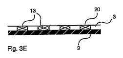
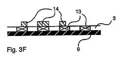
[0090] 図3A〜Hは、本発明の第3の実施形態の一例を示す。図3Aは、第1の色のデザイン画像化表面20を有するクリングフィルム13、例えば高度に可塑化されたPVCクリングフィルムを、初期リリースライナ6とともに示す。図3Bでは、この静電クリングフィルムアセンブリに孔10が有孔される。有孔クリングフィルム13は、光透過性フィルム層3を形成する。任意選択により、クリングフィルム13は、白色のデザイン画像化表面、例えば黒色の高度に可塑化されたPVCフィルムに積層された白色の高度に可塑化されたPVCフィルムまたは白色の印刷処理されたポリエステルフィルムを構成する。任意選択により、図3CおよびDに示すように、有孔初期リリースライナ6は除去され、そして図3Eに示すように、第1の色に対比する第2の色の交換リリースライナ9が付加されて、通常印刷会社に販売するための別のタイプの有孔フィルムアセンブリを形成する。図3Fは、有孔クリングフィルム13に与えられたデザイン14を示し、また図3Gは、交換ライナが除去されたことを示し、したがって図3Hに示すように、画像化された有孔クリングフィルム層13を透過性材料16、通常窓に付着させることが可能になる。
3A to H show an example of the third embodiment of the present invention. FIG. 3A shows a cling
[0091] 図4A〜Nは、本発明の第4の実施形態の一例を示す。図4Aは、キスカット可能な自己接着性フィルムアセンブリ42の平面図であり、図4Bには、接着層4を対比色のリリースライナ7とともに含む横断面X−Xを示す。画像化表面20を有するフェースストックフィルム層2は、切断パターン30状にキスカットされて、切断フィルムの細長い領域または「ストライプ」と、細長い領域34(II)の前縁を包含する任意選択の透過性リリースコーティング45とを提供し、米国特許出願第60/727,462号(国際特許出願第PCT/IB2006/004217号)に従って、切り口32間の自己接着性ビニル材料の長さにわたって、細長い領域34(I)を選択的に除去することを可能にする。図4Cは、デザイン14が画像化されたフェースストックフィルム層2を示し、同じく図4Dには横断面Y−Yを示す。図4Eは、例えばフェースストックフィルム層2に与えられたコネクタ領域37および/またはアプリケーションテープ(図示せず)を用いて、細長い領域34(I)が除去されたことを示す。リリースコーティング45は、細長い領域34(II)の前縁がこの処理で持ち上がるのを防止する。これは、PCT/IB2006/004217号に開示されている他の手段によって実現することもできる。こうして除去された切断フィルムは、図4HおよびJに示すように、透過性材料16に直接付着させることができ、または図4Fおよび4Gに示すように、対比色の交換リリースライナ9に付加して、例えば、画像化された切断フィルム自己接着性アセンブリを別の位置、例えば建物へ移動させ、対比色の交換リリースライナ9を除去した後、透過性材料16、例えば窓に付着させて、図4HおよびJに示すような視覚制御パネルを形成することができる(透過性リリース層45は図示せず)。図4Kは、対比色のリリースライナ7上に残っている細長い領域34(II)を備える画像化された切断フィルムを示し、同じく図4Lには横断面W−Wを示す。デザイン14は、対比色のリリースライナ7を背景に見ることができる。細長いフィルム領域34(II)は、残留するコネクタ領域35によって接続され、コネクタ領域35は、任意選択により、無孔リリースライナ7を除去して透過性材料16に付加した後、通常アプリケーションテープ(図示せず)を用いて図4Mおよび4Nの最終パネル内に保持され、または残留するコネクタ領域35は、任意選択により除去される。図4Pは、例えば、印刷機、例えばGerber Edge(商標)(米国Gerber Scientific Products社の商標)、熱質量転写デジタル印刷機の中をアセンブリが動くことができるように、切断パターン30および繰出し孔47を有する別のキスカット可能な自己接着性の切断フィルムアセンブリ42を示す。そうでない場合、アセンブリ42は通常、図4A〜Nと同様に、または例えば前述のもしくはPCT/IB2006/004217号に記載の他の変形形態と同様に処理される。上記の方法には、多くの潜在的な変形形態が存在する。例えば、自己接着性ビニルストライプをキスカットする前に、デザインをフェースストックフィルム層2に与えることができる。別の例として、リリース層45を必要とすることなく、アプリケーションテープによって交互の細長い領域を除去できることがわかった。
4A to N show an example of the fourth embodiment of the present invention. FIG. 4A is a plan view of a kiss-cuttable self-
[0092] 図5A〜Cは、本発明の第5の実施形態の一例を示す。図5Aの自己接着性の無孔透過性フィルムアセンブリ41は、無孔透過性フィルム23、例えばポリエステルフィルムと、接着層4、例えば透明のアクリルベースの感圧接着剤と、無孔リリースライナ7、例えば黒色または暗い灰色のシリコーンコーティング紙とを備える。図5Bでは、例えば黒色インク25上に白色のデザイン画像化表面20を有する白色インク24の第1の色のライン状の印刷パターン5が、例えば米国特許第RE37,186号に開示されている実質上正確な位置合わせ印刷の方法の1つによるスクリーン印刷によって印刷されている。デザイン14は、例えば米国特許第6,267,052号に開示されている異なる受容性を用いた印刷の方法の1つによって、例えばデジタルで与えられた顔料で着色した樹脂に対して受容性のある画像化表面20へのデザイン14のデジタル熱質量転写によって、画像化表面20に与えられ、一方無孔透過性フィルム23は、この画像化方法に受容性をもたず、印刷されたライン間は透過性のままになる。デザイン14は、デザイン画像化表面20の第1の色に対比する第2の色、例えばグレートーン70%の無孔リリースライナ7を背景に見られる。図5Dでは、無孔リリースライナ7は除去され、画像化された無孔透過性フィルム23が、接着層4を用いて透過性材料16、例えばガラス窓に付着されている。
FIGS. 5A to 5C show an example of the fifth embodiment of the present invention. The self-adhesive non-porous
[0093] 図6A〜Bは、本発明の第5の実施形態の別の例を示す。これは、黒色インク25上の通常白色インク24の印刷パターンが2つの層の正確な位置合わせを伴わない印刷方法によって与えられ、デザイン画像化表面20を有する白色インクライン24が黒色インクライン25の幅の範囲内に印刷されることを除いて、図5A〜Bの例に類似している。リリースライナ7は、第1の色、例えば白色に対比する第2の色、例えば黒色であり、それにより光学走査システムは、黒色インク25および黒色リリースライナ7の黒色の背景の下で、白色インク層24の範囲を識別すること、そしてデジタル印刷機に対して、図6Cに示すように、デザイン14を実質上白色インクライン24内に堆積させるように指示することができる。この処理には、図6Dの変形形態を役立てることができ、図6Dの変形形態では、デザイン14のラインは、黒色ライン25内ではあるが白色ライン24の外側に印刷される。例えば米国特許第6,210,776号によれば、デザインインクが半透明、例えばCMYKプロセスインクである場合、デザイン14は、白色インクライン24を背景に見えるが、ラインの黒色の縁部を背景とする可視性は実質上低減されて、白色ライン24を背景とするデザイン14の所望の演色性または知覚された色を提供するであろう。図6Eでは、無孔リリースライナ7は除去され、画像化された無孔透過性フィルム23が、接着層4、例えば透過性のアクリルベースの感圧接着剤を用いて、透過性材料16、例えばガラス窓に付着されている。
[0093] FIGS. 6A-B show another example of the fifth embodiment of the present invention. This is given by a printing method in which the printing pattern of the normal
[0094] 図7Aは、孔10を通して従来技術の白色のリリースライナ26が現れる、デザイン14が画像化された従来の有孔自己接着性フィルムアセンブリを表す。これは、図7Bの意図される完全なデザイン14より白く、明るく、弱く、淡い画像を生成する。図7Cは、この例ではグレートーン60%の対比色のライナ9が孔10を通って見える、本発明の一実施形態のアセンブリに付与された同じデザイン14を示す。これは、図7Aの従来技術の画像よりはるかに良好に図7Bの完全なデザインを表すことがわかる。本発明は、画像化されたアセンブリを受け取る際に消費者により良好な印象を提供し、また図7Aの従来技術のアセンブリの場合と比べて、印刷職人が良好な画像を得ようとして余分のインクを与える可能性を低くする。図7Cの画像ではまた、パネルの後ろの室内空間が比較的暗い場合に昼光で見たとき、窓に適用された画像化された有孔フィルムを備える視覚制御パネルがより良好に描写される。
FIG. 7A represents a conventional perforated self-adhesive film assembly with the
[0095] 上記の実施形態およびさらに多くの実施形態の1つまたは複数を用いると、光透過性フィルム層と、複数の個別の基層領域および/または複数の個別の基層を欠いている領域を含む印刷パターンと、第1の色のデザイン画像化表面を含む基層と、少なくとも10%のグレートーン間隔だけ第1の色に対比し、光透過性フィルム層を透かして見える第2の色の無孔材料を含むリリースライナとを備える、「うまく設計された基板」が形成されるように構成することが可能である。任意選択により、そのようなうまく設計された基板は、デザイン色層を備えるデザインを付与させて画像化された光透過性フィルム層を形成する印刷機への販売用に大量生産される。そのフィルム層上では、無孔材料の第2の色は通常、光透過性フィルム層を透かして見えたままであり、無孔材料は画像化され、または第2の色は、通常半透明の1つもしくは複数のデザイン色層と組み合わせて、また任意選択により1つもしくは複数のデザイン色層によって修正されて見える。デザインは、光透過性フィルム層の透過性部分において、現れた第2の色および/または修正された第2の色と組み合わせて見える。 [0095] Using one or more of the above embodiments and many more embodiments, includes a light transmissive film layer and a plurality of individual substrate regions and / or regions lacking a plurality of individual substrate layers A printed pattern, a base layer including a design imaging surface of a first color, and a non-porous second color visible through the light transmissive film layer in contrast to the first color by a gray tone spacing of at least 10%. It can be configured to form a “well-designed substrate” with a release liner containing material. Optionally, such well-designed substrates are mass produced for sale to a printing press that provides a design with a design color layer to form an imaged light transmissive film layer. On that film layer, the second color of the nonporous material usually remains visible through the light transmissive film layer, the nonporous material is imaged, or the second color is usually a translucent 1 It appears to be modified in combination with one or more design color layers and optionally with one or more design color layers. The design appears in combination with the second color that appears and / or the second color that has been modified in the transmissive portion of the light transmissive film layer.
[0096] 1つまたは複数の実施形態の前述の利益に加えて、画像化されたアセンブリは、シースルーグラフィックパネルの潜在的な消費者に、この製品が現場でどのように動作するのかを実証する有利な方法を提供する。白色無地の背景上に印刷された完全な画像は、現場で実現可能な品質のシースルーでは異なる印象を与え、これは必ずしも、完全な画像ほど良好であるいうわけではなく、また必要以上に期待を高めてその後不満を招く可能性があり、一方白色のリリースライナを有する従来技術のサンプルは、現場で実現可能な品質の非常に乏しい印象を与え、その結果ほぼ確実に、売上げの割合の損失をもたらす。本発明の1つまたは複数の実施形態の画像化されたアセンブリは、例えば建物および車両の窓上でシースルーグラフィックの潜在的な品質を写実的に実証するのに役立ち、したがって売上げに役立つであろう。 [0096] In addition to the aforementioned benefits of one or more embodiments, the imaged assembly demonstrates to a potential consumer of a see-through graphic panel how the product operates in the field. An advantageous method is provided. A complete image printed on a white solid background gives a different impression with the quality see-through that can be achieved in the field, which is not necessarily as good as a complete image and is more than expected. Prior art samples with white release liners give a very poor impression of quality achievable in the field, which almost certainly results in a loss in the percentage of sales. Bring. The imaged assembly of one or more embodiments of the present invention will help to realistically demonstrate the potential quality of see-through graphics, for example, on buildings and vehicle windows, and thus help sales. .
[0097] 前記に示した実施形態は、本発明の構造上および機能上の原理を説明するために提供され、限定するものではない。逆に、本発明の原理は、以下の特許請求の範囲の精神および範囲内のあらゆるすべての変更形態、改変形態、および/または置換えを包含するものである。 [0097] The embodiments set forth above are provided to illustrate the structural and functional principles of the invention and are not intended to be limiting. On the contrary, the principles of the invention are intended to embrace all such alterations, modifications and / or substitutions that fall within the spirit and scope of the following claims.
Claims (22)
(i)有孔フィルム、
(ii)複数の細長いフィルム層領域へと切断された切断フィルム層、または
(iii)無孔透過性フィルムに付与されたマーキング材料を含み、
前記印刷パターンが前記フィルム層を複数の個別の基層領域および/または複数の透過性領域に細分し、前記基層が第1の色のデザイン画像化表面を含み、前記リリースライナが無孔材料を含み、前記リリースライナがリリース表面を含み、
前記無孔材料が、前記光透過性フィルム層を通して見ると第2の色を有し、該第2の色が、前記第1の色のグレートーンとは少なくとも10%異なる該第2の色のグレートーンをもって前記第1の色と対比し、
前記第1の色が白色である、ことを特徴とするアセンブリ。 An assembly comprising a light transmissive film layer, a release liner, a pressure sensitive adhesive layer between the light transmissive film layer and the release liner, and a printed pattern, the printed pattern comprising a base layer, The base layer is
(I) a perforated film,
(Ii) a cutting film layer cut into a plurality of elongated film layer regions, or (iii) a marking material applied to a non-porous permeable film,
The printed pattern subdivides the film layer into a plurality of individual substrate regions and / or a plurality of transparent regions, the substrate layer includes a first color design imaging surface, and the release liner includes a non-porous material. The release liner includes a release surface;
The non-porous material has a second color when viewed through the light transmissive film layer, and the second color is at least 10% different from the first color gray tone. Contrast with the first color with a gray tone,
The assembly wherein the first color is white.
(i)フェースストックフィルム層と、該フェースストックフィルム層に着脱自在に取り付けられた初期リリースライナとを備える自己接着性アセンブリを提供するステップと、
(ii)前記印刷パターンの前記基層を、
(1)前記フェースストックフィルム層および前記初期リリースライナを通して前記自己接着性アセンブリに穴を開けて、前記基層を形成する有孔フェースストックフィルム層と、該有孔フェースストックフィルム層に着脱自在に取り付けられた有孔初期リリースライナとを形成し、また、前記第2の色の無孔材料を該有孔初期リリースライナに接着させて、該有孔初期リリースライナおよび該無孔材料が前記リリースライナを形成するステップ、
(2)前記フェースストックフィルム層および前記初期リリースライナを通して前記自己接着性アセンブリに穴を開けて、前記基層を形成する有孔フェースストックフィルム層と、該有孔フェースストックフィルム層に着脱自在に取り付けられた有孔初期リリースライナとを形成し、また、該有孔初期リリースライナを除去し且つ該有孔初期リリースライナを前記第2の色を有する前記リリースライナと交換するステップ、
(3)前記フェースストックフィルム層を前記フェースストックフィルム層の複数の細長い領域にキスカットし、交互の細長い領域を除去して前記基層を形成する複数の細長いフィルム領域を残し、前記初期リリースライナが前記第2の色を有し且つ前記リリースライナを形成する、ステップ、または
(4)前記印刷パターン内の前記基層を、透過性である前記フェースストックフィルム層上に付与するステップ
のうちの1つによって形成するステップとを含み、
前記リリースライナが、少なくとも10%のグレートーン間隔をもって前記第1の色と対比する第2の色の無孔材料を含み、
前記第2の色が、前記光透過性フィルム層を通して見ることができ、また
前記第1の色が白色である、方法。 A method of making an assembly, the assembly comprising a light transmissive film layer, a release liner, and a printing pattern, the printing pattern comprising a base layer, the printing pattern comprising a plurality of individual base layers. Subdividing a region and / or a plurality of individual transmissive regions, wherein the base layer includes a first color design imaging surface;
(I) providing a self-adhesive assembly comprising a facestock film layer and an initial release liner removably attached to the facestock film layer;
(Ii) the base layer of the print pattern;
(1) A perforated facestock film layer that forms a base layer by piercing the self-adhesive assembly through the facestock film layer and the initial release liner, and detachably attached to the perforated facestock film layer. And the second color non-porous material is adhered to the perforated initial release liner so that the perforated initial release liner and the non-porous material are the release liner. Forming steps,
(2) A perforated facestock film layer that forms a base layer by piercing the self-adhesive assembly through the facestock film layer and the initial release liner, and is detachably attached to the perforated facestock film layer. Forming a perforated initial release liner, and removing the perforated initial release liner and replacing the perforated initial release liner with the release liner having the second color;
(3) kiss-cut the facestock film layer into a plurality of elongated regions of the facestock film layer, removing alternate elongated regions to leave a plurality of elongated film regions forming the base layer, wherein the initial release liner is Having one of a second color and forming the release liner, or (4) applying one of the base layers in the printed pattern onto the facestock film layer that is transparent. Forming, and
The release liner includes a non-porous material of a second color that contrasts with the first color with a gray tone spacing of at least 10%;
The method wherein the second color is visible through the light transmissive film layer and the first color is white.
(i)有孔フィルム、
(ii)複数の細長いフィルム層領域へと切断された切断フィルム層、または
(iii)無孔透過性フィルムに付与されたマーキング材料を含み、
前記印刷パターンが前記フィルム層を複数の個別の基層領域および/または複数の透過性領域に細分し、前記基層が第1の色のデザイン画像化表面を含み、前記リリースライナが、第2の色を有する無孔材料を含み、該第2の色が、前記第1の色のグレートーンとは少なくとも10%異なる該第2の色のグレートーンをもって前記第1の色と対比し、前記リリースライナがリリース表面を含み、デザインが、前記デザイン画像化表面に付与されて画像化された光透過性フィルム層を形成するデザイン色層を含み、
前記無孔材料が、前記光透過性フィルム層を通して見ることができ、また、前記第2の色、または前記デザイン色層によって修正された前記第2の色が、前記光透過性フィルム層を通して見ることができ、
前記第1の色が白色である、ことを特徴とする画像化されたアセンブリ。 An imaged assembly comprising a light transmissive film layer, a release liner, a pressure sensitive adhesive layer between the light transmissive film layer and the release liner, and a printed pattern, wherein the printed pattern is a base layer And the base layer is
(I) a perforated film,
(Ii) a cutting film layer cut into a plurality of elongated film layer regions, or (iii) a marking material applied to a non-porous permeable film,
The printed pattern subdivides the film layer into a plurality of individual base layer regions and / or a plurality of transmissive regions, the base layer includes a first color design imaging surface, and the release liner includes a second color The release color of the second liner in contrast to the first color with a gray tone of the second color that is at least 10% different from the gray tone of the first color; Includes a release surface and the design includes a design color layer applied to the design imaging surface to form an imaged light transmissive film layer;
The non-porous material can be seen through the light transmissive film layer, and the second color, or the second color modified by the design color layer, is seen through the light transmissive film layer. It is possible,
An imaged assembly, wherein the first color is white.
該方法が、(iii)前記デザイン色層を含む前記デザインを与えて、画像化された光透過性フィルム層を形成するステップをさらに含み、
前記無孔材料が前記光透過性フィルム層を通して見ることができ、前記無孔材料が画像化されておらず、または前記第2の色が、通常半透明の1つもしくは複数のデザイン色層と組み合わせて且つ任意選択により1つもしくは複数のデザイン色層によって修正されて見ることができ、また、前記デザインが、前記光透過性フィルム層の前記透過性領域において、前記現れた第2の色および/または修正された第2の色と組み合わせて見ることができる、方法。 The method of claim 9, further comprising a design wherein the assembly includes a design color layer;
And (iii) providing the design including the design color layer to form an imaged light transmissive film layer;
The non-porous material is visible through the light transmissive film layer, the non-porous material is not imaged, or the second color is usually translucent with one or more design color layers Can be viewed in combination and optionally modified by one or more design color layers, and the design can be seen in the transmissive region of the light transmissive film layer with the second color and A method that can be viewed in combination with a modified second color.
(ii)少なくとも10%のグレートーン間隔をもって前記第1の色と対比する前記第2の色の前記リリースライナを除去するステップと、
(iii)前記画像化された光透過性フィルム層を透過性材料に付与するステップとをさらに含む、請求項9に記載の方法。 (I) providing a design to the design imaging surface of the first color to form an imaged light transmissive film layer;
(Ii) removing the release liner of the second color that contrasts with the first color with a gray tone spacing of at least 10%;
10. The method of claim 9, further comprising: (iii) applying the imaged light transmissive film layer to a transmissive material.
Applications Claiming Priority (3)
| Application Number | Priority Date | Filing Date | Title |
|---|---|---|---|
| US94188207P | 2007-06-04 | 2007-06-04 | |
| US60/941,882 | 2007-06-04 | ||
| PCT/IB2008/052189 WO2008149301A2 (en) | 2007-06-04 | 2008-06-04 | Vision control panel assembly with a contrasting colored liner |
Publications (3)
| Publication Number | Publication Date |
|---|---|
| JP2010529498A JP2010529498A (en) | 2010-08-26 |
| JP2010529498A5 JP2010529498A5 (en) | 2011-07-21 |
| JP5802388B2 true JP5802388B2 (en) | 2015-10-28 |
Family
ID=40094254
Family Applications (1)
| Application Number | Title | Priority Date | Filing Date |
|---|---|---|---|
| JP2010510941A Active JP5802388B2 (en) | 2007-06-04 | 2008-06-04 | Visual control panel assembly with contrasting color liner |
Country Status (9)
| Country | Link |
|---|---|
| US (1) | US8394477B2 (en) |
| EP (2) | EP2505376B1 (en) |
| JP (1) | JP5802388B2 (en) |
| CN (1) | CN101754865B (en) |
| AU (1) | AU2008259392B2 (en) |
| CA (1) | CA2688609C (en) |
| HK (1) | HK1141768A1 (en) |
| PL (1) | PL2505376T3 (en) |
| WO (1) | WO2008149301A2 (en) |
Families Citing this family (11)
| Publication number | Priority date | Publication date | Assignee | Title |
|---|---|---|---|---|
| US8283617B2 (en) * | 2009-03-05 | 2012-10-09 | Silitek Electronic (Guangzhou) Co., Ltd. | Display device and light sensing system |
| US9604428B2 (en) | 2010-08-24 | 2017-03-28 | James Walker | Ventilated structural panels and method of construction with ventilated structural panels |
| US9091049B2 (en) * | 2010-08-24 | 2015-07-28 | James Walker | Ventilated structural panels and method of construction with ventilated structural panels |
| CN103826867B (en) | 2011-07-08 | 2017-03-22 | 反相有限公司 | Open perforated material and method of imaging to form a vision control panel |
| WO2013175298A1 (en) * | 2012-05-25 | 2013-11-28 | Contra Vision Ltd. | Perforated adhesive assembly with removable non-perforated bonding layer |
| USD740035S1 (en) * | 2013-04-29 | 2015-10-06 | Vorwek & Co. Interholding Gmbh | Floor covering with dot pattern |
| CN106915195A (en) * | 2015-12-24 | 2017-07-04 | 兴亮工业有限公司 | Panel and its manufacture method with multi-level drawing and stereochemical structure |
| US20170192245A1 (en) * | 2015-12-31 | 2017-07-06 | Sheng-Wen Lai | Panel Assembly with a Three-Dimensional Visual Effect |
| WO2019055469A1 (en) * | 2017-09-12 | 2019-03-21 | Corning Incorporated | Deadfront for displays including a touch panel on decorative glass and related methods |
| US11065960B2 (en) | 2017-09-13 | 2021-07-20 | Corning Incorporated | Curved vehicle displays |
| JP6512563B1 (en) * | 2018-06-04 | 2019-05-15 | 株式会社サンリュウ | Image representing method and image representing product using base material having convex portion |
Family Cites Families (23)
| Publication number | Priority date | Publication date | Assignee | Title |
|---|---|---|---|---|
| DE3574579D1 (en) | 1984-07-28 | 1990-01-11 | Contra Vision Ltd | Platte. |
| JPH0739166B2 (en) | 1991-12-13 | 1995-05-01 | 本州製紙株式会社 | Colored release sheet |
| US5250336A (en) * | 1992-02-11 | 1993-10-05 | Morgan Adhesives Company | Colored release liner |
| US5609938A (en) | 1993-06-23 | 1997-03-11 | Creative Minds Foundation, Inc. | Image display apparatus with holes for opposite side viewing |
| US5773110A (en) * | 1994-02-28 | 1998-06-30 | Creative Minds Foundation | Window painting apparatus and method |
| GB9426401D0 (en) | 1994-12-30 | 1995-03-01 | Contra Vision Ltd | Perforated adhesive assembly |
| GB9521797D0 (en) | 1995-10-24 | 1996-01-03 | Contra Vision Ltd | Partial printing of a substrate |
| GB9600247D0 (en) | 1996-01-06 | 1996-03-06 | Contra Vision Ltd | Panel with light permeable images |
| AU730258B2 (en) | 1996-06-14 | 2001-03-01 | Minnesota Mining And Manufacturing Company | Display unit and methods of displaying an image |
| ES2175474T3 (en) * | 1996-10-24 | 2002-11-16 | Contra Vision Ltd | METHOD FOR FORMING LASTING IMAGES ON SUBSTRATES. |
| JPH10282918A (en) | 1997-04-02 | 1998-10-23 | Max Co Ltd | Display method for unidirectional see-through image |
| JPH10278379A (en) * | 1997-04-09 | 1998-10-20 | Seiko Epson Corp | Printer printing method, and recording medium |
| CN2293470Y (en) * | 1997-08-05 | 1998-10-07 | 王水木 | Decorative sheet with visual effect |
| CN1305412A (en) * | 1998-06-15 | 2001-07-25 | 美国3M公司 | Multi-component unidirectional graphic article |
| JP2000081842A (en) | 1998-09-07 | 2000-03-21 | Kimoto & Co Ltd | Sheet for manufacturing display plate |
| US6506475B1 (en) | 2001-01-19 | 2003-01-14 | Contra Vision Ltd. | Partial printing of a substrate with edge sealed printed portions |
| JP3080805U (en) | 2001-04-03 | 2001-10-12 | 宣彦 宮澄 | Translucent light film for window glass |
| US20020162874A1 (en) | 2001-05-07 | 2002-11-07 | 3M Innovative Properties Company | Adhesive film constructions with detectable transparent release liners |
| US6899775B2 (en) | 2002-01-23 | 2005-05-31 | Contra Vision Ltd. | Printing with differential adhesion |
| US20050112315A1 (en) * | 2003-11-06 | 2005-05-26 | Farmer Michael S. | Transfer product with contrasting backing |
| CN1914287A (en) * | 2004-02-02 | 2007-02-14 | 3M创新有限公司 | Method of producing colored graphic marking films |
| NZ552669A (en) | 2004-07-02 | 2009-06-26 | Gsp Print Pty Ltd | A method of printing and images printed thereby |
| CA2623742A1 (en) | 2005-09-27 | 2007-10-11 | Contra Vision Ltd. | Method of making a vision control panel using cut film |
-
2008
- 2008-06-04 EP EP12169357.6A patent/EP2505376B1/en active Active
- 2008-06-04 CN CN200880025306.5A patent/CN101754865B/en active Active
- 2008-06-04 EP EP08763192A patent/EP2170624A2/en not_active Withdrawn
- 2008-06-04 AU AU2008259392A patent/AU2008259392B2/en active Active
- 2008-06-04 WO PCT/IB2008/052189 patent/WO2008149301A2/en active Application Filing
- 2008-06-04 PL PL12169357T patent/PL2505376T3/en unknown
- 2008-06-04 JP JP2010510941A patent/JP5802388B2/en active Active
- 2008-06-04 US US12/663,184 patent/US8394477B2/en active Active
- 2008-06-04 CA CA2688609A patent/CA2688609C/en not_active Expired - Fee Related
-
2010
- 2010-09-02 HK HK10108321.1A patent/HK1141768A1/en not_active IP Right Cessation
Also Published As
| Publication number | Publication date |
|---|---|
| AU2008259392B2 (en) | 2014-02-13 |
| HK1141768A1 (en) | 2010-11-19 |
| JP2010529498A (en) | 2010-08-26 |
| PL2505376T3 (en) | 2017-05-31 |
| EP2505376B1 (en) | 2016-10-19 |
| WO2008149301A2 (en) | 2008-12-11 |
| WO2008149301A3 (en) | 2009-07-23 |
| AU2008259392A1 (en) | 2008-12-11 |
| CN101754865B (en) | 2013-06-19 |
| US20100181020A1 (en) | 2010-07-22 |
| EP2170624A2 (en) | 2010-04-07 |
| US8394477B2 (en) | 2013-03-12 |
| CA2688609A1 (en) | 2008-12-11 |
| CN101754865A (en) | 2010-06-23 |
| CA2688609C (en) | 2016-02-16 |
| EP2505376A1 (en) | 2012-10-03 |
Similar Documents
| Publication | Publication Date | Title |
|---|---|---|
| JP5802388B2 (en) | Visual control panel assembly with contrasting color liner | |
| EP1093418B1 (en) | Unidirectional graphic article and method for making | |
| US8343611B2 (en) | One way vision film for ink jet printing, printing film, and method for producing them | |
| JP2007527803A (en) | Method for producing colored graphic marking film | |
| US20060010735A1 (en) | License plate frame | |
| CN102941717A (en) | See-through film and manufacturing method thereof | |
| JP2010529498A5 (en) | ||
| US20050123707A1 (en) | Method for printing unidirectional and see-through graphics | |
| DE69919871T2 (en) | LUMINIZING, PERFORATED, SINGLE-SIDED FOIL | |
| US6582801B1 (en) | Signage with opaque and transparent elements and method of making the same | |
| JP2004226478A (en) | Transparent sticker and its manufacturing method | |
| EP4094241A1 (en) | Aerospace warning tags | |
| JP6585566B2 (en) | sticker | |
| JP2005232889A (en) | Method for manufacturing one-way perspective decorative sheet | |
| JPH08132794A (en) | Decoration sheet | |
| JP3044297U (en) | Porous printing film with double printed images and characters | |
| KR20060074010A (en) | Polypropylene synthetic paper for inkjet blackout and manufacturing method thereof | |
| JP2014000707A (en) | Image recorded matter and image recording method | |
| MXPA97009720A (en) | Method to manufacture a luminescent reproduction, and reproduction results |
Legal Events
| Date | Code | Title | Description |
|---|---|---|---|
| A521 | Request for written amendment filed |
Free format text: JAPANESE INTERMEDIATE CODE: A523 Effective date: 20110603 |
|
| A621 | Written request for application examination |
Free format text: JAPANESE INTERMEDIATE CODE: A621 Effective date: 20110603 |
|
| A977 | Report on retrieval |
Free format text: JAPANESE INTERMEDIATE CODE: A971007 Effective date: 20120815 |
|
| A131 | Notification of reasons for refusal |
Free format text: JAPANESE INTERMEDIATE CODE: A131 Effective date: 20120918 |
|
| A601 | Written request for extension of time |
Free format text: JAPANESE INTERMEDIATE CODE: A601 Effective date: 20121212 |
|
| A602 | Written permission of extension of time |
Free format text: JAPANESE INTERMEDIATE CODE: A602 Effective date: 20121219 |
|
| A601 | Written request for extension of time |
Free format text: JAPANESE INTERMEDIATE CODE: A601 Effective date: 20130115 |
|
| A602 | Written permission of extension of time |
Free format text: JAPANESE INTERMEDIATE CODE: A602 Effective date: 20130122 |
|
| A601 | Written request for extension of time |
Free format text: JAPANESE INTERMEDIATE CODE: A601 Effective date: 20130218 |
|
| A602 | Written permission of extension of time |
Free format text: JAPANESE INTERMEDIATE CODE: A602 Effective date: 20130225 |
|
| A521 | Request for written amendment filed |
Free format text: JAPANESE INTERMEDIATE CODE: A523 Effective date: 20130315 |
|
| A131 | Notification of reasons for refusal |
Free format text: JAPANESE INTERMEDIATE CODE: A131 Effective date: 20140106 |
|
| A601 | Written request for extension of time |
Free format text: JAPANESE INTERMEDIATE CODE: A601 Effective date: 20140404 |
|
| A602 | Written permission of extension of time |
Free format text: JAPANESE INTERMEDIATE CODE: A602 Effective date: 20140411 |
|
| A601 | Written request for extension of time |
Free format text: JAPANESE INTERMEDIATE CODE: A601 Effective date: 20140502 |
|
| A602 | Written permission of extension of time |
Free format text: JAPANESE INTERMEDIATE CODE: A602 Effective date: 20140513 |
|
| A601 | Written request for extension of time |
Free format text: JAPANESE INTERMEDIATE CODE: A601 Effective date: 20140602 |
|
| A602 | Written permission of extension of time |
Free format text: JAPANESE INTERMEDIATE CODE: A602 Effective date: 20140609 |
|
| A02 | Decision of refusal |
Free format text: JAPANESE INTERMEDIATE CODE: A02 Effective date: 20141211 |
|
| A521 | Request for written amendment filed |
Free format text: JAPANESE INTERMEDIATE CODE: A523 Effective date: 20150410 |
|
| A911 | Transfer to examiner for re-examination before appeal (zenchi) |
Free format text: JAPANESE INTERMEDIATE CODE: A911 Effective date: 20150605 |
|
| TRDD | Decision of grant or rejection written | ||
| A01 | Written decision to grant a patent or to grant a registration (utility model) |
Free format text: JAPANESE INTERMEDIATE CODE: A01 Effective date: 20150803 |
|
| A61 | First payment of annual fees (during grant procedure) |
Free format text: JAPANESE INTERMEDIATE CODE: A61 Effective date: 20150831 |
|
| R150 | Certificate of patent or registration of utility model |
Ref document number: 5802388 Country of ref document: JP Free format text: JAPANESE INTERMEDIATE CODE: R150 |
|
| R250 | Receipt of annual fees |
Free format text: JAPANESE INTERMEDIATE CODE: R250 |
|
| R250 | Receipt of annual fees |
Free format text: JAPANESE INTERMEDIATE CODE: R250 |
|
| R250 | Receipt of annual fees |
Free format text: JAPANESE INTERMEDIATE CODE: R250 |
|
| R250 | Receipt of annual fees |
Free format text: JAPANESE INTERMEDIATE CODE: R250 |
|
| R250 | Receipt of annual fees |
Free format text: JAPANESE INTERMEDIATE CODE: R250 |
|
| R250 | Receipt of annual fees |
Free format text: JAPANESE INTERMEDIATE CODE: R250 |