JP5800553B2 - Distribution device, video distribution method, and program - Google Patents
Distribution device, video distribution method, and program Download PDFInfo
- Publication number
- JP5800553B2 JP5800553B2 JP2011085651A JP2011085651A JP5800553B2 JP 5800553 B2 JP5800553 B2 JP 5800553B2 JP 2011085651 A JP2011085651 A JP 2011085651A JP 2011085651 A JP2011085651 A JP 2011085651A JP 5800553 B2 JP5800553 B2 JP 5800553B2
- Authority
- JP
- Japan
- Prior art keywords
- video
- communication path
- data
- image
- quality
- Prior art date
- Legal status (The legal status is an assumption and is not a legal conclusion. Google has not performed a legal analysis and makes no representation as to the accuracy of the status listed.)
- Active
Links
- 238000000034 method Methods 0.000 title claims description 21
- 230000005540 biological transmission Effects 0.000 claims description 95
- 238000004891 communication Methods 0.000 claims description 83
- 230000008569 process Effects 0.000 claims description 10
- 238000012360 testing method Methods 0.000 description 12
- 238000012545 processing Methods 0.000 description 8
- 230000004048 modification Effects 0.000 description 7
- 238000012986 modification Methods 0.000 description 7
- 238000010586 diagram Methods 0.000 description 6
- 230000007423 decrease Effects 0.000 description 4
- 230000004044 response Effects 0.000 description 3
- 230000008054 signal transmission Effects 0.000 description 3
- 230000008901 benefit Effects 0.000 description 1
- 230000008859 change Effects 0.000 description 1
- 230000006835 compression Effects 0.000 description 1
- 238000007906 compression Methods 0.000 description 1
- 230000006866 deterioration Effects 0.000 description 1
- 238000005516 engineering process Methods 0.000 description 1
- 230000000737 periodic effect Effects 0.000 description 1
- 230000009467 reduction Effects 0.000 description 1
- 230000002194 synthesizing effect Effects 0.000 description 1
Images


Classifications
-
- H—ELECTRICITY
- H04—ELECTRIC COMMUNICATION TECHNIQUE
- H04N—PICTORIAL COMMUNICATION, e.g. TELEVISION
- H04N21/00—Selective content distribution, e.g. interactive television or video on demand [VOD]
- H04N21/60—Network structure or processes for video distribution between server and client or between remote clients; Control signalling between clients, server and network components; Transmission of management data between server and client, e.g. sending from server to client commands for recording incoming content stream; Communication details between server and client
- H04N21/63—Control signaling related to video distribution between client, server and network components; Network processes for video distribution between server and clients or between remote clients, e.g. transmitting basic layer and enhancement layers over different transmission paths, setting up a peer-to-peer communication via Internet between remote STB's; Communication protocols; Addressing
- H04N21/637—Control signals issued by the client directed to the server or network components
- H04N21/6377—Control signals issued by the client directed to the server or network components directed to server
-
- H—ELECTRICITY
- H04—ELECTRIC COMMUNICATION TECHNIQUE
- H04N—PICTORIAL COMMUNICATION, e.g. TELEVISION
- H04N21/00—Selective content distribution, e.g. interactive television or video on demand [VOD]
- H04N21/20—Servers specifically adapted for the distribution of content, e.g. VOD servers; Operations thereof
- H04N21/23—Processing of content or additional data; Elementary server operations; Server middleware
- H04N21/234—Processing of video elementary streams, e.g. splicing of video streams or manipulating encoded video stream scene graphs
- H04N21/23418—Processing of video elementary streams, e.g. splicing of video streams or manipulating encoded video stream scene graphs involving operations for analysing video streams, e.g. detecting features or characteristics
-
- H—ELECTRICITY
- H04—ELECTRIC COMMUNICATION TECHNIQUE
- H04N—PICTORIAL COMMUNICATION, e.g. TELEVISION
- H04N21/00—Selective content distribution, e.g. interactive television or video on demand [VOD]
- H04N21/60—Network structure or processes for video distribution between server and client or between remote clients; Control signalling between clients, server and network components; Transmission of management data between server and client, e.g. sending from server to client commands for recording incoming content stream; Communication details between server and client
- H04N21/63—Control signaling related to video distribution between client, server and network components; Network processes for video distribution between server and clients or between remote clients, e.g. transmitting basic layer and enhancement layers over different transmission paths, setting up a peer-to-peer communication via Internet between remote STB's; Communication protocols; Addressing
- H04N21/631—Multimode Transmission, e.g. transmitting basic layers and enhancement layers of the content over different transmission paths or transmitting with different error corrections, different keys or with different transmission protocols
-
- H—ELECTRICITY
- H04—ELECTRIC COMMUNICATION TECHNIQUE
- H04N—PICTORIAL COMMUNICATION, e.g. TELEVISION
- H04N21/00—Selective content distribution, e.g. interactive television or video on demand [VOD]
- H04N21/80—Generation or processing of content or additional data by content creator independently of the distribution process; Content per se
- H04N21/81—Monomedia components thereof
- H04N21/816—Monomedia components thereof involving special video data, e.g 3D video
Landscapes
- Engineering & Computer Science (AREA)
- Multimedia (AREA)
- Signal Processing (AREA)
- Two-Way Televisions, Distribution Of Moving Picture Or The Like (AREA)
Description
本発明は、複数の無線送信機と複数の無線受信機との間の複数の通信経路を介して映像データを複数の映像出力装置へ伝送する技術に関する。 The present invention relates to a technique for transmitting video data to a plurality of video output devices via a plurality of communication paths between a plurality of wireless transmitters and a plurality of wireless receivers.
複数のプロジェクタを用いて分割された映像を投影し、投影された画像を合成して大画面映像を表示するシステムや輝度が不足するプロジェクタの画像を複数重ねて表示するシステムがある。更に、左右の画像を重ねて3D映像を表示するシステム等、大画面を複数の画像として表示するマルチプロジェクションシステムもある。 There are a system for projecting divided images using a plurality of projectors and combining the projected images to display a large screen image and a system for displaying a plurality of images of projectors with insufficient brightness. In addition, there are multi-projection systems that display a large screen as a plurality of images, such as a system that displays 3D images by overlapping left and right images.
このような大画像のマルチプロジェクションシステムの映像は、高品位な画質も求められ、映像データは膨大になる。また、画面の大型化に伴い、プロジェクタ及び映像ソース間の距離が延び、配線が複数化するため、ワイヤレス化への要望が非常に大きくなってきている。 Such a large image multi-projection system image is required to have high image quality, and the image data is enormous. In addition, as the screen becomes larger, the distance between the projector and the video source is increased, and the number of wirings is increased. Therefore, there is a great demand for wireless.
無線通信システムにおいては、MIMO技術やミリ波伝送等、大容量化がなされてきているが、大画像、高品位の圧縮されていない映像を複数のプロジェクタに送信するためには複数の無線通信装置を用いて複数のチャネルで通信する必要がある。 In wireless communication systems, the capacity has been increased, such as MIMO technology and millimeter wave transmission, but in order to transmit large images and high-quality uncompressed images to a plurality of projectors, a plurality of wireless communication devices It is necessary to communicate using a plurality of channels.
例えば、特許文献1では、複数の映像データを複数のチャネルを用いて伝送する技術が提案されている()。特許文献1では、複数の伝送チャネルの合計伝送レート内で、画像チャネルごとの発生情報量に応じて、画像チャネルごとに伝送レートを可変にしている。さらに、1伝送チャネルの伝送レート以上に多く割り当てられた画像チャネルのデータを、隣接する画像チャネルに対応する伝送チャネルを利用して伝送している。 For example, Patent Document 1 proposes a technique for transmitting a plurality of video data using a plurality of channels (). In Patent Document 1, within the total transmission rate of a plurality of transmission channels, the transmission rate is made variable for each image channel according to the amount of information generated for each image channel. Further, image channel data allocated more than the transmission rate of one transmission channel is transmitted using a transmission channel corresponding to an adjacent image channel.
複数の映像データを複数の無線通信機で送受信するマルチプロジェクションシステムにおいて、無線通信の電磁波の遮蔽物や、他の通信機器による電波干渉等により伝搬環境が変化すると、必要な伝送レートが維持できない場合がある。1つの通信経路の伝送レートが低下すると、その通信経路を介して伝送される映像が乱れ、大画面映像の場合、乱れのある映像と乱れの無い映像とのつなぎ目が目立ち、映像全体の画質が低下してしまう。 In a multi-projection system that transmits and receives multiple video data with multiple wireless communication devices, the required transmission rate cannot be maintained if the propagation environment changes due to radio wave shielding or radio interference from other communication devices. There is. When the transmission rate of one communication path is reduced, the video transmitted through the communication path is disrupted. In the case of a large screen video, the connection between the disordered video and the video without disturbance is noticeable, and the image quality of the entire video is reduced. It will decline.
また、3D映像や輝度を向上させるために映像を重ね合わせる場合、高品位の映像と低品位の映像が重ね合わされると、低品位の映像による画像の乱れが際立ち、全体の映像の画質の低下が目立つことがある。 Also, when superimposing 3D video and video to improve brightness, if high-quality video and low-quality video are overlaid, image disturbance due to low-quality video will stand out and the quality of the entire video will deteriorate. May stand out.
本発明は、複数の通信経路のいずれかの伝送レートが低下しても、合成して表示される各映像を均質化することを目的とする。 An object of the present invention is to homogenize each video displayed in combination even if the transmission rate of any of a plurality of communication paths decreases.
本発明は、第1の通信経路と当該第1の通信経路よりも伝送レートが小さい第2の通信経路とを介して伝送された少なくとも第1の映像と第2の映像を合成して表示する映像表示システムにおける分配装置であって、前記第1の通信経路と前記第2の通信経路の伝送レートの和に基づいて前記第1の映像と前記第2の映像の品質が均質になるように書く映像の品質を決定する決定手段と、前記複数の通信経路それぞれの伝送レートと前記決定手段により決定された品質に基づいて、前記第1の通信経路に前記第1の映像と前記第2の映像の一部とを分配し、前記第2の通信経路に前記第2の映像の残りを分配する分配手段と、を有することを特徴とする。
The present invention is displayed by synthesizing at least a first image and the second image than the first communication path and the first communication path is transmitted via a second communication path transmission rate is less A distribution device in a video display system, wherein the quality of the first video and the second video is uniform based on a sum of transmission rates of the first communication path and the second communication path determining means for determining the quality of the image writing based on the determined quality by the plurality of communication paths each transmission rate and said determining means, said first image and said second to said first communication path distributing a portion of the image, and having a a distribution means for distributing the remainder of said second image on the second communication path.
本発明によれば、複数の通信経路のいずれかの伝送レートが低下しても、合成して表示される各映像の品質の違いによる映像全体の画質低下を抑制できる。 ADVANTAGE OF THE INVENTION According to this invention, even if the transmission rate of any one of several communication paths falls, the image quality fall of the whole image | video by the difference in the quality of each image | video displayed by composition can be suppressed.
以下、図面を参照しながら発明を実施するための形態について詳細に説明する。実施の形態では、複数の通信経路を介して伝送された少なくとも2つの映像を合成して表示する映像表示システムにおける分配装置及び映像分配方法について説明する。 Hereinafter, embodiments for carrying out the invention will be described in detail with reference to the drawings. In the embodiment, a distribution device and a video distribution method in a video display system that synthesizes and displays at least two videos transmitted via a plurality of communication paths will be described.
尚、複数の通信経路が、第1の通信経路と第2の通信経路の場合を説明するが、本発明はこれに限定されるものではない。また、第1の映像と第2の映像を映像分配する場合を説明するが、本発明はこれに限定されるものではない。 Although the case where the plurality of communication paths are the first communication path and the second communication path will be described, the present invention is not limited to this. Although the case where the first video and the second video are distributed will be described, the present invention is not limited to this.
[第1の実施形態]
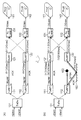
図1の(A)は通常の伝送状態を示す図である。一方、図1の(B)は障害物によって無線送信機(TxRF)から無線受信機(RxRF)への無線通信経路が妨害され、壁の反射パスを用いたため、データ伝送量が低下した場合の動作を示す図である。尚、以下の説明では、無線送信機及び無線受信機を単に送信機及び受信機と呼ぶ。
[First Embodiment]
FIG. 1A shows a normal transmission state. On the other hand, (B) of FIG. 1 shows a case where the obstacle is that the wireless communication path from the wireless transmitter (TxRF) to the wireless receiver (RxRF) is obstructed and the reflection path of the wall is used, so that the data transmission amount decreases. It is a figure which shows operation | movement. In the following description, the wireless transmitter and the wireless receiver are simply referred to as a transmitter and a receiver.
本実施例では、プロジェクタ141が大画面の右側の映像を映写し、プロジェクタ142が左側の映像を映写し、これら左右の映像をつなぎ合わせることで大画面の映像を映写するシステムを例に説明する。しかしながら、プロジェクタ141、142の各映像を重ね合わせて映写映像の輝度を向上させるシステム、プロジェクタ141、142が3D映像の左右の映像を映写し、これら映像を重ねて3D化した映像を表示するシステムであっても本発明を適用できる。
In the present embodiment, an example of a system in which the
図1に示すデータ分配器(TxDiv)101は、1つの映像データが右側映像(HDMI1)と左側画像(HDMI2)に分割された各映像データを入力し、複数の映像出力装置(プロジェクタ)141、142の映像データに分配する。送信機111、112はそれぞれの映像データを無線送信する。受信機121、122はそれぞれの映像データを受信する。データ合成器131、132は、受信機121、122の両方に有線で接続されている。なお、データ分配機101に右側映像(HDMI1)と左側画像(HDMI2)が入力される構成を例に説明するが、データ分配機101が1つの映像を右側映像と左側画像とに分割する構成にしてもよい。
A data distributor (TxDiv) 101 shown in FIG. 1 inputs video data obtained by dividing one video data into a right video (HDMI1) and a left video (HDMI2), and a plurality of video output devices (projectors) 141, It distributes to 142 video data. The
プロジェクタ141、142は、伝送レートが2Gbpsの通信経路を介して映像を伝送すれば、最高品位の映像を得ることができるものとする。ここで、図1の(A)のように、送信機111及び受信機121と、送信機112及び受信機122との間の通信経路の伝送レートがそれぞれ2Gbpsで通信できている場合、プロジェクタ141、142から映写される映像は最高品位である。データ分配機101はプロジェクタ141の映像データのみを送信機111に分配し、プロジェクタ142の映像データのみを送信機112に分配する。送信機111への映像データのヘッダには映像データの宛先が全てプロジェクタ141であることを示す内容が含まれる。また同様に、送信機112への映像データのヘッダには映像データの宛先が全てプロジェクタ142であることを示す内容が含まれる。
It is assumed that the
受信機121は、データ合成器131、132の両方に有線で接続されているが、受信されたヘッダの内容に従ってデータ合成器131のみに映像データを送信し、データ合成器131からプロジェクタ141へ全ての映像データが送信される。受信機122も、データ合成器131、132の両方に有線で接続され、受信されたヘッダの内容に従ってデータ合成器132のみに映像データを送信し、データ合成器132からプロジェクタ142へ全ての映像データが送信される。
The
図1の(B)では、送信機111及び受信機121の間の通信経路は最高品位の2Gbpsの伝送レートでで通信できている。一方、送信機112及び受信機122の間の通信経路は伝送レートが1Gbpsの品位でしか通信できていない。そこで、データ分配器101は合計で3Gbpsの伝送レートで通信するように映像データの品質を決め、各通信経路で伝送される映像データの分配を決定する。つまり、プロジェクタ141、142のぞれぞれに、1.5Gbpsの伝送レートで映像が伝送されるように映像品質を決定し、入力された映像の品質を調整する。映像品質の調整は、映像の解像度又は階調度のビット幅を調整することにより行われる。しかしながら、映像の圧縮率を調整してもよいし、フレームレートを調整してもよいし、両方を調整しても、他の方法により調整してもよい。
In FIG. 1B, the communication path between the
データ分配器101は、送信機111及び受信機121の間の通信経路の2Gbpsの伝送レートのうち、プロジェクタ141宛ての映像データに1.5Gbpsを割り当て、プロジェクタ142宛ての映像データに0.5Gbpsを割り当てる。そしてこれらの伝送レートで伝送する映像データを送信機111に分配する。また、送信機112及び受信機122の間の通信経路の1Gbpsの伝送レートの全てをプロジェクタ142の映像データに割り当て、1Gbpsで伝送する映像データを送信機112に分配する。この分配は、プロジェクタ142に伝送する1.5Gbpsの映像データのうち、0.5Gbps分のパケットをを送信機111に分配し、1.0Gbps分のパケットを送信機112に分配すればよい。
The
送信機111への映像データのヘッダには1.5Gbpsの映像データの宛先がプロジェクタ141であり、0.5Gbpsの映像データの宛先がプロジェクタ142であることを示す内容が含まれる。一方、送信機112への映像データのヘッダには映像データの宛先が全てプロジェクタ142であることを示す内容が含まれる。
The header of the video data to the
受信機121は、受信されたヘッダの内容に従ってデータ合成器131に1.5Gbpsの伝送レートで伝送されたプロジェクタ141宛ての映像データを送信する。更に、受信機121は、データ合成器132に0.5Gbpsの伝送レート伝送されたプロジェクタ142宛ての映像データを送信する。これにより、データ合成器131からプロジェクタ141へ1.5Gbpsの伝送レートで伝送された映像データが送信される。受信機122は、受信されたヘッダの内容に従ってデータ合成器132のみに1Gbpsの伝送レートで伝送されたプロジェクタ142宛ての映像データを送信する。そして、データ合成器132により受信機121から送信された0.5Gbpsの映像データと合成されてプロジェクタ142へ1.5Gbpsの映像データが送信される。
The
上述したように、複数のプロジェクタに伝送される映像データの品質を均質化することにより、左右の映像出力が均質化され、映像の境界を目立たなくすることが可能になる。 As described above, by homogenizing the quality of the video data transmitted to the plurality of projectors, the left and right video outputs are homogenized, and the video boundaries can be made inconspicuous.
ここで、第1の実施形態におけるデータ分配器、送信機、及び受信機によって行われる全体的な処理を、図2を用いて説明する。まず、データ分配器は、複数の通信経路の初期状態を調べるために、接続されている全ての送信機から全ての受信機へテスト信号を送信させるテスト信号送信指示を行う(201)。次に、全ての受信機から返されてきた肯定応答(Ack)から各通信経路の伝送レートを把握する(202)。尚、図1に示す例では送信機及び受信機は各々2台であるが、映像画面の大きさ、分割の仕方、伝送レート等で通信経路の必要数が変化するので、この台数に限定されるものではない。 Here, the overall processing performed by the data distributor, transmitter, and receiver in the first embodiment will be described with reference to FIG. First, the data distributor issues a test signal transmission instruction for transmitting a test signal from all connected transmitters to all receivers in order to check the initial states of a plurality of communication paths (201). Next, the transmission rate of each communication path is grasped from the acknowledgments (Ack) returned from all receivers (202). In the example shown in FIG. 1, there are two transmitters and two receivers each. However, the required number of communication paths varies depending on the size of the video screen, the way of division, the transmission rate, etc., so the number is limited to this number. It is not something.
次に、データ分配器は、全ての通信経路の伝送レートの総和を算出し、総和の伝送レートで伝送できるデータ量に基づいて、映像品質を決定する(203)。さらに、各プロジェクタに伝送される映像の画質が均質化されるように、各プロジェクタに伝送される映像の品質を調整することにより、各プロジェクタに伝送される映像データの量を決定する。そして、データ分配器は、各通信経路の伝送レートに合わせて、各送信機から送信させる複数の映像データのデータ配分を決定する(204)。次に、データ分配器は、各送信機に送信させる映像データにヘッダを挿入する(205)。尚、ヘッダには、データ配分に従って決定された映像データの宛先、データ量、順番、伝送レート等の情報が含まれる。 Next, the data distributor calculates the sum of the transmission rates of all the communication paths, and determines the video quality based on the amount of data that can be transmitted at the total transmission rate (203). Further, the amount of video data transmitted to each projector is determined by adjusting the quality of the video transmitted to each projector so that the image quality of the video transmitted to each projector is homogenized. Then, the data distributor determines data distribution of the plurality of video data to be transmitted from each transmitter in accordance with the transmission rate of each communication path (204). Next, the data distributor inserts a header into the video data to be transmitted to each transmitter (205). The header includes information such as the destination of the video data, the data amount, the order, and the transmission rate determined according to the data distribution.
次に、データ分配器は、通信経路が確保されていない送信機を除く全ての送信機に対してヘッダを挿入したデータを送信する(206)。その後、通信経路の伝送レートを把握する処理に戻り、各送信機が送信した映像データに対する肯定応答から各通信経路の伝送レートの把握を行う。 Next, the data distributor transmits the data with the header inserted to all transmitters except the transmitter for which the communication path is not secured (206). Thereafter, the process returns to the process of grasping the transmission rate of the communication path, and the transmission rate of each communication path is grasped from the acknowledgment for the video data transmitted by each transmitter.
また、各送信機では、初期状態として伝送レートが最大に設定されている(211)。そして、送信機がデータ分配器からテスト信号送信指示を受けると、受信機へテスト信号を送信する(212)。このテスト信号の送信後、受信機から肯定応答(Ack)を受信するのを待ち(213)、肯定応答を受信できなければ、伝送レートが最小か判断する(214)。判断の結果、最小でなければ、伝送レートの引き下げを行い(215)、受信機にテスト信号を送信する処理に戻る。ここで、最小の伝送レートでも、肯定応答を受信できない場合、その伝送ルートは切断する(216)。一方、肯定応答を受信できた場合、その時の伝送レートを保存し、データ分配器に伝送レートを伝える。 In each transmitter, the transmission rate is set to the maximum as the initial state (211). When the transmitter receives a test signal transmission instruction from the data distributor, the transmitter transmits a test signal to the receiver (212). After transmission of this test signal, it waits for reception of an acknowledgment (Ack) from the receiver (213). If the acknowledgment is not received, it is determined whether the transmission rate is minimum (214). If it is not the minimum as a result of the determination, the transmission rate is reduced (215), and the process returns to the process of transmitting the test signal to the receiver. Here, if an acknowledgment cannot be received even at the minimum transmission rate, the transmission route is disconnected (216). On the other hand, if an acknowledgment is received, the transmission rate at that time is stored, and the transmission rate is transmitted to the data distributor.
また、その後のデータ伝送時には、テスト信号の肯定応答を受信できた伝送レートでデータを送信する(217)。そして、肯定応答の受信を待ち(218)、肯定応答を受信できないときは、テスト信号の送信と同様に、最小伝送ルートか判断する(219)。判断の結果、最小でなければ、伝送レートの引き下げを行う(21a)。ここで、最小の伝送レートでも、肯定応答を受信できなければ、その伝送ルートは切断する(21b)。 In subsequent data transmission, data is transmitted at a transmission rate at which an acknowledgment of the test signal was received (217). Then, it waits for reception of an affirmative response (218). If an affirmative response cannot be received, it is determined that the transmission route is the minimum transmission route as in the case of transmission of the test signal (219). If the result of determination is not the minimum, the transmission rate is reduced (21a). If no acknowledgment is received even at the minimum transmission rate, the transmission route is disconnected (21b).
更に、各受信機では、送信機からテスト信号又はデータを受信し(221、223)、受信できた場合には肯定応答を送信する(222、224)。 Furthermore, each receiver receives a test signal or data from the transmitter (221, 223), and transmits an affirmative response (222, 224) if it can be received.
次に、通信経路(無線伝送パス)の切り替えを伴う場合の送信機及び受信機の処理を、図3を用いて説明する。ここでは、送信機及び受信機の間の無線伝送パス切り替えを伴う以外は変わらないため、図2に示すデータ分配器の処理は省いている。 Next, processing of the transmitter and the receiver when switching communication paths (wireless transmission paths) is described with reference to FIG. Here, since there is no change except accompanied by switching of the wireless transmission path between the transmitter and the receiver, the processing of the data distributor shown in FIG. 2 is omitted.
図3では、図2に示す処理に次の処理が追加されている点が異なる。つまり、受信機の肯定応答に含まれる受信品質が予め決められた閾値以上か否かを判定し(301、304)、閾値以上でない場合に、同じ閾値以上の無線伝送パスがあれば(302、305)、その無線伝送パスに切り替える(303、306)。このように、無線伝送パス切り替えと伝送レートの引き下げの2重ループにより、最適な伝送パスで且つ最大伝送レートでデータ送信が可能となる。 FIG. 3 is different in that the following processing is added to the processing shown in FIG. That is, it is determined whether or not the reception quality included in the acknowledgment of the receiver is equal to or higher than a predetermined threshold (301, 304), and if it is not equal to or higher than the threshold, if there is a wireless transmission path equal to or higher than the threshold (302, 304). 305) and switch to the wireless transmission path (303, 306). In this way, data transmission can be performed at the optimum transmission path and at the maximum transmission rate by the double loop of the radio transmission path switching and the transmission rate reduction.
このように、データ分配器101は、全通信経路の伝送レートの総和に応じて、解像度又は階調度のビット幅を調整する。更に、各通信経路を介して伝送する各プロジェクタへの映像データの映像品質及びデータ量を調整し、各プロジェクタから出力される映像品質をほぼ等しくする。そして、映像データをそれぞれ無線パケットサイズに細分化し、送信機111、112へ送信する。ここで、映像データをパケットサイズに細分化する際に、複数のプロジェクタ141、142の映像が均質化されるように、各通信経路の伝送レートと各通信経路で伝送する映像データの比率と各映像データのパケットサイズを決定する。
As described above, the
図4に、図1に示す送信機111、112のパケット構成の一例を示す。図4の(A)は、図1の(A)における送信機111、112から送信されるパケットの構成を示す図である。パケットは、プリアンブル411、421、ヘッダ412、422、データ区間413、423、CRC(周期的冗長検査)415、425で構成されている。ここで、映像データを伝送する場合、映像データを伝送するパケットに加え、不図示のAck受信期間、次の映像データ用のプリアンブルまでの待ち時間を含む時間で必要なデータを伝送する必要がある。従って、スループットが2Gbpsの映像データを伝送する通信経路の場合は、データ区間413、423での伝送レートは2Gbpsより大きい。ヘッダ412、422には、データ区間413、423の伝送レート又はその伝送レートを実現する時の変調方式(図1では16QAM)、符号化率、データ長等の情報が含まれる。そして、これらの情報からプロジェクタ141、142の映像データのスループット2Gbpsが実現される。
FIG. 4 shows an example of the packet configuration of the
図4の(B)は、図1の(B)における送信機111、112のパケットの構成を示す図である。パケットの構成は図4の(A)の場合と同様である。しかし、図4の(B)の送信機111のヘッダ432は、変調方式、符号化率等の情報、データ区間433、434の位置と長さ、データ区間434がプロジェクタ142用のどの部分のデータかを示す情報等を含んでいる。また、送信機112のヘッダ442は、伝送レートが下がった後の変調方式(図1ではQPSK)、符号化率等の情報と、プロジェクタ142用のどの部分のデータかを示す情報等を含んでいる。
FIG. 4B is a diagram illustrating a packet configuration of the
尚、図4にはパケット内のデータの長さでデータシェアを行う方法の一例を示したが、OFDM変調のサブキャリア等、異なるデータシェアを行ってもよい。 Although FIG. 4 shows an example of a method for performing data sharing based on the length of data in the packet, different data sharing such as OFDM modulation subcarriers may be performed.
ここで、第1の実施形態の変形例を、図5、図6を用いて説明する。図5は、変形例1の構成例を示すブロック図である。変形例1では、受信機121、122はそれぞれ一つのデータ合成器131、132に接続され、データ合成器131、132はデータ伝送が双方向に可能なように有線で接続されている。データ合成器131は受信した映像データのヘッダの内容に従って映像データをプロジェクタ141またはデータ合成器132に送信する。同様に、データ合成器132は受信した映像データのヘッダの内容に従って映像データをプロジェクタ142またはデータ合成器131に送信する。図5(B)の例では、データ合成器131は受信した映像データのうち、プロジェクタ141宛ての1.5Gbpsの映像データをプロジェクタ141に送信する。また、データ合成器131は受信した映像データのうち、プロジェクタ142宛ての0.5Gbpsの映像データをデータ合成器132に送信する。データ合成器132は、データ合成器131から受信した0.5Gbpsの映像データと受信機122から受信した1Gbpsの映像データとを合成し、プロジェクタ142に送信する。この構成によれば、受信機とデータ合成器の数が多い場合や受信機とデータ合成器の距離が離れている場合に有効でなる。
Here, the modification of 1st Embodiment is demonstrated using FIG. 5, FIG. FIG. 5 is a block diagram illustrating a configuration example of the first modification. In the first modification, each of the
図6は、変形例2の構成例を示すブロック図である。変形例2では、送信機111及び受信機121と、送信機112及び受信機122とが64QAMで通信可能で、各無線通信経路は3Gbpsに相当するデータ伝送レートがある。一方、プロジェクタ141、142、143はそれぞれ2Gbpsのスループットがあればよく、プロジェクタ3台分のデータを無線通信経路2本で伝送できる。図6の(A)は、送信機111及び受信機121の間でプロジェクタ141用のデータ2Gbpsとプロジェクタ143用のデータ1Gbpsを伝送する。そして、送信機112及び受信機122の間でプロジェクタ142用のデータ2Gbpsとプロジェクタ143用のデータ1Gbpsを伝送する。ここで、データ合成器131、132はプロジェクタ143用のデータ1Gbps分をデータ合成器133に有線経由で送信する。そして、データ合成器133では、それらの映像データを合成してプロジェクタ143に送信する。
FIG. 6 is a block diagram illustrating a configuration example of the second modification. In the second modification, the
図6の(B)は、送信機112及び受信機122の間で伝送レートが1Gbpsになると、送信機111及び受信機121の間でプロジェクタ141、143、142の映像データをそれぞれ1.3Gbps、1.3Gbps、0.3Gbps伝送する。一方、送信機112及び受信機122の間ではプロジェクタ142のデータ1Gbpsのみを伝送する。データ合成器131ではそれぞれのプロジェクタのデータを分離し、プロジェクタ143、142用の映像データを有線経由で送信する。データ合成器133ではプロジェクタ143、142用の映像データからプロジェクタ143用のデータのみを選択、分離し、プロジェクタ143へ伝送する。また、データ合成器132ではプロジェクタ143、142用の映像データからプロジェクタ142用の映像データのみを選択、分離し、受信機122で受信された映像データと合成してプロジェクタ142へ伝送する。
6B shows that when the transmission rate between the
第1の実施形態では、プロジェクタ数と無線通信経路の数が一致している場合と、プロジェクタ数が無通信経路の数より多い場合を説明したが、これに限定されるものではなく、無線通信経路の数がプロジェクタ数より多くてもよい。 In the first embodiment, the case where the number of projectors matches the number of wireless communication paths and the case where the number of projectors is larger than the number of non-communication paths have been described. However, the present invention is not limited to this. The number of routes may be larger than the number of projectors.
以上のように本実施例によれば、一部の通信経路の伝送レートが低下しても、各映像出力装置から出力される映像品質をほぼ等しく均質化することができる。また、複数の通信経路全体の伝送レートに基づいて映像品質を決め、各通信経路で伝送する映像を決めるので、通信経路を効率よく利用でき、出力される映像品質をより高くすることができる。例えば、各映像出力装置から出力された映像をつなぎ合わせて大画面化する場合には、各画像の画質の違いによるつなぎ目の目立ちを抑制できる。また、各映像出力装置から出力された映像を重ね合わせて輝度をあげたり、3D化する場合にも映像全体の画質低下を抑制できる。 As described above, according to the present embodiment, the video quality output from each video output device can be homogenized almost equally even if the transmission rates of some communication paths are lowered. Further, since the video quality is determined based on the transmission rate of the entire plurality of communication paths and the video to be transmitted through each communication path is determined, the communication path can be used efficiently and the output video quality can be further improved. For example, when the video output from each video output device is connected to make a large screen, the conspicuousness of the joint due to the difference in image quality of each image can be suppressed. In addition, even when the video output from each video output device is superimposed to increase the brightness or to make it 3D, it is possible to suppress the deterioration of the image quality of the entire video.
[第2の実施形態]
次に、図面を参照しながら本発明に係る第2の実施形態を、図7、図8を用いて詳細に説明する。尚、図7に示す構成要素において、図1に示す第1の実施形態と同じ構成要素には同じ番号を用いている。
[Second Embodiment]
Next, a second embodiment according to the present invention will be described in detail with reference to FIGS. In addition, in the component shown in FIG. 7, the same number is used for the same component as 1st Embodiment shown in FIG.
第2の実施形態では、送信機111及び受信機121がデータ分配器101とプロジェクタ141との間のデータ伝送線の置き換えを目的に挿入されている。また、送信機112及び受信機122もデータ分配器101とプロジェクタ142との間のデータ伝送線の置き換えを目的に挿入されている。
In the second embodiment, the
この構成において、データ分配器101は、プロジェクタ141、142が同じ画質になるように映像データを分配する。また、図7の(B)のように、送信機112及び受信機122の間の通信経路が障害物152によって妨害され、反射パスで伝送レートが低くなった場合、低くなった経路に合わせて送信機111及び受信機121の間の通信経路の伝送レートも下げる。これにより、プロジェクタ141、142へのスループットが等しくなり、画質が均質化されるため、一方の画質の低下により画像の継ぎ目が気になることはない。
In this configuration, the
図8は、第1の実施形態におけるデータ分配器、送信機、及び受信機によって行われる全体的な処理を示すフローチャートである。図8において、送信機及び受信機の動作は、図2と同様である。 FIG. 8 is a flowchart showing the overall processing performed by the data distributor, transmitter, and receiver in the first embodiment. In FIG. 8, the operations of the transmitter and the receiver are the same as those in FIG.
データ分配器は、通信経路の初期状態を調べるために、接続されている全ての送信機から受信機へテスト信号を送信させるテスト信号送信指示を行う(201)。次に、第2の実施形態では、全通信経路を最小伝送レートの通信経路に合わせるため、切断されているルートがないことを確認する(802)。もし、切断されている通信経路が存在する場合は、その経路の送信機に通信経路が確立されるまでテスト信号を送信させる。切断ルートがなくなると、全ての送信機が受信した肯定応答から各通信経路の伝送レートを把握する(202)。尚、図8では送信機及び受信機はそれぞれ2台を例に説明したが、映像画面の大きさ、分割の仕方、伝送レート等で通信経路の必要数が変化するので、この台数に限定されるものではない。 In order to check the initial state of the communication path, the data distributor issues a test signal transmission instruction for transmitting a test signal from all the connected transmitters to the receiver (201). Next, in the second embodiment, in order to match all communication paths to the communication path with the minimum transmission rate, it is confirmed that there is no disconnected route (802). If there is a communication path that is disconnected, the transmitter of that path is caused to transmit a test signal until the communication path is established. When there is no disconnection route, the transmission rate of each communication path is grasped from the acknowledgments received by all transmitters (202). In FIG. 8, two transmitters and receivers have been described as examples. However, since the required number of communication paths varies depending on the size of the video screen, the way of division, the transmission rate, etc., the number is limited to this number. It is not something.
次に、データ分配器は、全ての送信機の肯定応答からそれぞれの伝送レートがわかると、最小伝送レートに合わせて、プロジェクタの映像品質を決定する(803)。そして、データ分配器は、各送信機に送信させるデータの前にヘッダを挿入する(804)。このヘッダには、決定された伝送レート等の情報が含まれる。次に、データ分配器は、各送信機に対してヘッダを挿入した映像データを送信する(206)。その後、切断されているルートがないかを判定する処理に戻り、各送信機が送信した映像データに対する肯定応答から各通信経路の伝送経路の伝送レートの把握を行う。 Next, when each transmission rate is known from the acknowledgments of all transmitters, the data distributor determines the video quality of the projector in accordance with the minimum transmission rate (803). Then, the data distributor inserts a header before the data to be transmitted to each transmitter (804). This header includes information such as the determined transmission rate. Next, the data distributor transmits the video data with the header inserted to each transmitter (206). Thereafter, the process returns to the process for determining whether there is a disconnected route, and the transmission rate of the transmission path of each communication path is grasped from the acknowledgment for the video data transmitted by each transmitter.
以上、複数の映像データを複数の無線通信装置で伝送し、複数の映像出力装置を用いて複数の映像データを合成して1つの映像を表示するシステムにおいて、無線伝送する際に、伝送レートに合わせて複数の映像データから出力される映像の品質を均質化できる。 As described above, in a system in which a plurality of video data is transmitted by a plurality of wireless communication devices, and a plurality of video data is synthesized using a plurality of video output devices to display one video, the transmission rate is set to the transmission rate. In addition, the quality of video output from a plurality of video data can be homogenized.
また、映像のスループットの変更の仕方として、映像の最小ピクセルの大きさを変えたり、色調の分解能を変える等、様々な方法が考えられるが、映像のスループットの変更の仕方も本発明の適応範囲外である。 Various methods of changing the video throughput are conceivable, such as changing the minimum pixel size of the video and changing the resolution of the color tone. The method of changing the video throughput is also applicable to the present invention. Outside.
[他の実施形態]
また、本発明は、以下の処理を実行することによっても実現される。即ち、上述した実施形態の機能を実現するソフトウェア(プログラム)を、ネットワーク又は各種記憶媒体を介してシステム或いは装置に供給し、そのシステム或いは装置のコンピュータ(またはCPUやMPU等)がプログラムを読み出して実行する処理である。
[Other Embodiments]
The present invention can also be realized by executing the following processing. That is, software (program) that realizes the functions of the above-described embodiments is supplied to a system or apparatus via a network or various storage media, and a computer (or CPU, MPU, or the like) of the system or apparatus reads the program. It is a process to be executed.
Claims (6)
前記第1の通信経路と前記第2の通信経路の伝送レートの和に基づいて前記第1の映像と前記第2の映像の品質が均質になるように各映像の品質を決定する決定手段と、
前記決定手段により決定された品質に基づいて、前記第1の通信経路に前記第1の映像と前記第2の映像の一部とを分配し、前記第2の通信経路に前記第2の映像の残りを分配する分配手段と、
を有することを特徴とする分配装置。 In a video display system for combining and displaying at least a first video and a second video transmitted via a first communication path and a second communication path having a transmission rate smaller than that of the first communication path A dispensing device,
Determining means for determining the quality of each video so that the quality of the first video and the second video is uniform based on a sum of transmission rates of the first communication path and the second communication path ; ,
Based on the quality determined by pre SL determining means, wherein a portion of the first image and the second image is distributed to the first communication path, the second to the second communication path A distribution means for distributing the rest of the video ;
A dispensing device comprising:
前記分配装置の決定手段が、前記第1の通信経路の伝送レートと前記第2の通信経路の伝送レートの和に基づいて前記第1の映像と前記第2の映像の品質が均質になるように各映像の品質を決定する工程と、
前記分配装置の分配手段が、前記決定された品質に基づいて、前記第1の通信経路に前記第1の映像と前記第2の映像の一部とを分配し、前記第2の通信経路に前記第2の映像の残りを分配する工程と、
を有することを特徴とする分配装置の映像分配方法。 In the video display system for displaying by combining at least a first image and a second image is also transmitted via the second communication path transmission rate is less than the first communication path and the first communication path A video distribution method for a distribution device, comprising:
The determining unit of the distribution device makes the quality of the first video and the second video uniform based on the sum of the transmission rate of the first communication path and the transmission rate of the second communication path. The process of determining the quality of each video ,
Said dispensing means dispensing device based on the prior SL determined quality, the first distributing a portion of the first image and the second image to the communication path, said second communication path Distributing the remainder of the second video to
A video distribution method for a distribution apparatus, comprising:
Priority Applications (2)
| Application Number | Priority Date | Filing Date | Title |
|---|---|---|---|
| JP2011085651A JP5800553B2 (en) | 2011-04-07 | 2011-04-07 | Distribution device, video distribution method, and program |
| US13/435,866 US20120257114A1 (en) | 2011-04-07 | 2012-03-30 | Distribution apparatus and video distribution method |
Applications Claiming Priority (1)
| Application Number | Priority Date | Filing Date | Title |
|---|---|---|---|
| JP2011085651A JP5800553B2 (en) | 2011-04-07 | 2011-04-07 | Distribution device, video distribution method, and program |
Publications (3)
| Publication Number | Publication Date |
|---|---|
| JP2012222571A JP2012222571A (en) | 2012-11-12 |
| JP2012222571A5 JP2012222571A5 (en) | 2014-05-15 |
| JP5800553B2 true JP5800553B2 (en) | 2015-10-28 |
Family
ID=46965844
Family Applications (1)
| Application Number | Title | Priority Date | Filing Date |
|---|---|---|---|
| JP2011085651A Active JP5800553B2 (en) | 2011-04-07 | 2011-04-07 | Distribution device, video distribution method, and program |
Country Status (2)
| Country | Link |
|---|---|
| US (1) | US20120257114A1 (en) |
| JP (1) | JP5800553B2 (en) |
Families Citing this family (5)
| Publication number | Priority date | Publication date | Assignee | Title |
|---|---|---|---|---|
| JP2014082550A (en) | 2012-10-12 | 2014-05-08 | Canon Inc | Communication device, communication method, and program |
| JP6055117B2 (en) * | 2014-01-09 | 2016-12-27 | 株式会社Pfu | Network video transmission system, transmission video switching method, and program |
| WO2015140897A1 (en) * | 2014-03-17 | 2015-09-24 | 株式会社 東芝 | Electronic device, moving image data transfer method and program |
| KR102209292B1 (en) * | 2015-11-04 | 2021-01-29 | 삼성전자 주식회사 | Method and apparatus for providing data in multimedia system |
| WO2017209573A1 (en) * | 2016-06-03 | 2017-12-07 | Samsung Electronics Co., Ltd. | Multi-point content transmission method and apparatus |
Family Cites Families (12)
| Publication number | Priority date | Publication date | Assignee | Title |
|---|---|---|---|---|
| JPH1141608A (en) * | 1997-07-23 | 1999-02-12 | Matsushita Electric Ind Co Ltd | Image transmitter, image coding method and image coder |
| JP4489932B2 (en) * | 2000-11-27 | 2010-06-23 | 富士通株式会社 | System and method for synchronizing multiple communications |
| US20040098753A1 (en) * | 2002-03-20 | 2004-05-20 | Steven Reynolds | Video combiner |
| US9325998B2 (en) * | 2003-09-30 | 2016-04-26 | Sharp Laboratories Of America, Inc. | Wireless video transmission system |
| JP3882929B2 (en) * | 2004-03-29 | 2007-02-21 | セイコーエプソン株式会社 | Image processing system, projector, and image processing method |
| US20090122207A1 (en) * | 2005-03-18 | 2009-05-14 | Akihiko Inoue | Image Display Apparatus, Image Display Monitor, and Television Receiver |
| JP4727401B2 (en) * | 2005-12-02 | 2011-07-20 | 日本電信電話株式会社 | Wireless multicast transmission system, wireless transmission device, and wireless multicast transmission method |
| US9544602B2 (en) * | 2005-12-30 | 2017-01-10 | Sharp Laboratories Of America, Inc. | Wireless video transmission system |
| JP4301262B2 (en) * | 2006-08-08 | 2009-07-22 | セイコーエプソン株式会社 | Multi-display system and display method |
| JP5033598B2 (en) * | 2007-11-28 | 2012-09-26 | 株式会社日立製作所 | Display device and video equipment |
| US8786711B2 (en) * | 2007-12-12 | 2014-07-22 | Nec Corporation | Image quality evaluation system, and apparatus, method and program used for the evaluation system |
| JP2010109932A (en) * | 2008-10-31 | 2010-05-13 | Toshiba Corp | Multi-display system and coding control method |
-
2011
- 2011-04-07 JP JP2011085651A patent/JP5800553B2/en active Active
-
2012
- 2012-03-30 US US13/435,866 patent/US20120257114A1/en not_active Abandoned
Also Published As
| Publication number | Publication date |
|---|---|
| JP2012222571A (en) | 2012-11-12 |
| US20120257114A1 (en) | 2012-10-11 |
Similar Documents
| Publication | Publication Date | Title |
|---|---|---|
| JP5800553B2 (en) | Distribution device, video distribution method, and program | |
| KR101640508B1 (en) | Method and system for progressive rate adaptation for uncompressed video communication in wireless systems | |
| JP7262877B2 (en) | Adaptive High Dynamic Range Tonemapping with Overlay Directives | |
| US9661189B2 (en) | Method and apparatus for adaptive rate-based image data transmission and reception | |
| KR101826701B1 (en) | Method and system for multiplexing data streaming in audio/video networks | |
| US9660836B2 (en) | Network topology discovery | |
| US12089082B1 (en) | Multichannel communication systems | |
| WO2013108676A1 (en) | Multiple gateway device, multiple line communication system, multiple line communication method and program | |
| CN101895745B (en) | Wireless transmitter, wireless transmission method, wireless receiver and wireless reception method | |
| US8973074B2 (en) | Method and system for isochronous communication in audio/video networks | |
| JP6048091B2 (en) | COMMUNICATION DEVICE, COMMUNICATION METHOD, AND COMMUNICATION PROGRAM | |
| US20120151537A1 (en) | Method and system for asynchronous and isochronous data transmission in a high speed video network | |
| US8963996B2 (en) | Communication of stereoscopic three-dimensional (3D) video information including an uncompressed eye view video frames | |
| US9886980B2 (en) | Method for synchronizing A/V streams | |
| JP6467822B2 (en) | Display system, transmission device, and display system control method | |
| JP2016225922A (en) | Radio communication system and method | |
| KR20130099515A (en) | Apparatas and method of displaying a contents using for key frame in a terminal | |
| US9003466B2 (en) | Method and system for isochronous data stream management in high speed audio/video networks | |
| US20140082685A1 (en) | Method and apparatus for adjusting data transmission rate in a wireless communication system | |
| GB2522468A (en) | Methods and devices for distributing video data in a multi-display system using a collaborative video cutting scheme | |
| JP2016225744A (en) | Radio communication system and method | |
| US10728466B2 (en) | Video multiviewer systems | |
| US20240267487A1 (en) | Video transmission apparatus, video receiving apparatus, video transmission method, video receiving method, video transmission system, and program | |
| US20140139516A1 (en) | Image processing apparatus with transmission formats and control method thereof | |
| JP2020088659A (en) | Transmission device, reception device, and video signal transmission/reception system |
Legal Events
| Date | Code | Title | Description |
|---|---|---|---|
| A521 | Written amendment |
Free format text: JAPANESE INTERMEDIATE CODE: A523 Effective date: 20140328 |
|
| A621 | Written request for application examination |
Free format text: JAPANESE INTERMEDIATE CODE: A621 Effective date: 20140328 |
|
| A977 | Report on retrieval |
Free format text: JAPANESE INTERMEDIATE CODE: A971007 Effective date: 20141225 |
|
| A131 | Notification of reasons for refusal |
Free format text: JAPANESE INTERMEDIATE CODE: A131 Effective date: 20150126 |
|
| A521 | Written amendment |
Free format text: JAPANESE INTERMEDIATE CODE: A523 Effective date: 20150317 |
|
| TRDD | Decision of grant or rejection written | ||
| A01 | Written decision to grant a patent or to grant a registration (utility model) |
Free format text: JAPANESE INTERMEDIATE CODE: A01 Effective date: 20150727 |
|
| A61 | First payment of annual fees (during grant procedure) |
Free format text: JAPANESE INTERMEDIATE CODE: A61 Effective date: 20150825 |
|
| R151 | Written notification of patent or utility model registration |
Ref document number: 5800553 Country of ref document: JP Free format text: JAPANESE INTERMEDIATE CODE: R151 |