JP5799503B2 - Submerged plasma generator, submerged plasma processing apparatus, submerged plasma generating method, and submerged plasma processing method - Google Patents
Submerged plasma generator, submerged plasma processing apparatus, submerged plasma generating method, and submerged plasma processing method Download PDFInfo
- Publication number
- JP5799503B2 JP5799503B2 JP2010293135A JP2010293135A JP5799503B2 JP 5799503 B2 JP5799503 B2 JP 5799503B2 JP 2010293135 A JP2010293135 A JP 2010293135A JP 2010293135 A JP2010293135 A JP 2010293135A JP 5799503 B2 JP5799503 B2 JP 5799503B2
- Authority
- JP
- Japan
- Prior art keywords
- liquid
- unit
- microwave
- electric field
- plasma
- Prior art date
- Legal status (The legal status is an assumption and is not a legal conclusion. Google has not performed a legal analysis and makes no representation as to the accuracy of the status listed.)
- Active
Links
Images


Landscapes
- Plasma Technology (AREA)
- Physical Or Chemical Processes And Apparatus (AREA)
Description
本発明の実施形態は、液中プラズマ発生装置、液中プラズマ処理装置、液中プラズマ発生方法、および液中プラズマ処理方法に関する。 Embodiments described herein relate generally to a submerged plasma generator, a submerged plasma processing apparatus, a submerged plasma generation method, and a submerged plasma processing method.
近年、液体中に含まれている有機物、有害物質、細菌類などの分解や、液体から反応生成物を生成するためにプラズマ処理が用いられるようになってきている。
このようなプラズマ処理においては、散気装置や超音波振動装置などにより液体中に気泡を生成し、この気泡を放電空間とするようにしている(例えば、特許文献1を参照)。 そのため、液体中に気泡を生成するための散気装置や超音波振動装置などが必要となり、装置の大型化や高コスト化などを招いていた。
また、散気装置や超音波振動装置などにより液体中に気泡を生成する場合には、生成された気泡中の圧力が大気圧以上となる。そのため、気泡中においてプラズマを発生させることが困難となり、この観点からも装置の大型化や高コスト化などを招いていた。
In recent years, plasma treatment has been used to decompose organic substances, harmful substances, bacteria, and the like contained in liquids and generate reaction products from liquids.
In such plasma processing, bubbles are generated in a liquid by an air diffuser, an ultrasonic vibration device, or the like, and these bubbles are used as a discharge space (see, for example, Patent Document 1). For this reason, an air diffuser or an ultrasonic vibration device for generating bubbles in the liquid is required, leading to an increase in size and cost of the device.
In addition, when bubbles are generated in the liquid using an air diffuser, an ultrasonic vibration device, or the like, the pressure in the generated bubbles is equal to or higher than atmospheric pressure. For this reason, it is difficult to generate plasma in the bubbles, and from this viewpoint, the apparatus is increased in size and cost.
また、気泡中においてプラズマを発生させるために、高電圧が印加される金属電極を液体中に設ける必要があった。そのため、金属電極が液体に触れることで腐食したり、金属電極が腐食することで液体が金属汚染されたりするおそれがある。
この場合、液体が金属汚染されるとプラズマ処理された液体の用途が限定されるおそれがある。例えば、プラズマ処理された液体を半導体装置などの電子デバイスの洗浄などに用いる場合には、金属汚染などの問題が生じるおそれがある。
また、特許文献1のようにマイクロ波を気泡に印加するものはあっても、マイクロ波を共振させていないため、放電着火がし難くなるおそれがあった。
Further, in order to generate plasma in the bubbles, it is necessary to provide a metal electrode to which a high voltage is applied in the liquid. Therefore, there is a possibility that the metal electrode is corroded by touching the liquid, or the metal is corroded by the metal electrode being corroded.
In this case, if the liquid is contaminated with metal, the use of the plasma-treated liquid may be limited. For example, when the plasma-treated liquid is used for cleaning an electronic device such as a semiconductor device, a problem such as metal contamination may occur.
Further, even if there is a device that applies a microwave to a bubble as in Patent Document 1, since the microwave is not resonated, there is a risk that it is difficult to perform discharge ignition.
本発明が解決しようとする課題は、液体の金属汚染を抑制することができる液中プラズマ発生装置、液中プラズマ処理装置、液中プラズマ発生方法、および液中プラズマ処理方法を提供することである。 The problem to be solved by the present invention is to provide an in-liquid plasma generator, an in-liquid plasma processing apparatus, an in-liquid plasma generation method, and an in-liquid plasma processing method capable of suppressing liquid metal contamination. .
実施形態によれば、液体を供給する液体供給部と、マイクロ波を発生させるマイクロ波発生部と、前記液体の流速を上昇させることで前記液体の圧力を減圧させて気泡を発生させるまたは前記気泡を発生させやすくする減圧部と、前記マイクロ波を共振させ、前記共振させたマイクロ波の電界を空間的に集中、または、パルス状に印加して前記マイクロ波を前記減圧部に放射する共振部と、を備え、前記減圧部により、前記液体と、前記共振部と、が離隔されたことを特徴とする液中プラズマ発生装置が提供される。 According to the embodiment, a liquid supply unit that supplies a liquid, a microwave generation unit that generates a microwave, and a bubble is generated by reducing a pressure of the liquid by increasing a flow rate of the liquid, or the bubble And a resonating unit that resonates the microwave and spatially concentrates the electric field of the resonated microwave or applies a pulse to radiate the microwave to the depressurizing unit. The in-liquid plasma generator is provided in which the liquid and the resonance unit are separated by the decompression unit.
また、他の実施形態によれば、上記の液中プラズマ発生装置と、前記液中プラズマ発生装置でプラズマ処理された液体により処理される被処理物を載置する載置部と、を備えたことを特徴とする液中プラズマ処理装置が提供される。 Moreover, according to another embodiment, the above-mentioned submerged plasma generation device and a mounting unit that mounts an object to be processed by the liquid plasma-processed by the submerged plasma generation device are provided. An in-liquid plasma processing apparatus is provided.
また、他の実施形態によれば、液体の流速を上昇させることで前記液体の圧力を減圧させて気泡を発生させる工程と、マイクロ波を発生させる工程と、共振器を用いて前記マイクロ波を共振させる工程と、前記共振させたマイクロ波の電界を空間的に集中、または、パルス状に印加して前記マイクロ波を前記気泡が発生した領域に放射する工程と、を備え、前記マイクロ波を放射する工程において、前記共振器と、前記液体と、を誘電体により離隔したことを特徴とする液中プラズマ発生方法が提供される。 According to another embodiment, the step of generating bubbles by reducing the pressure of the liquid by increasing the flow rate of the liquid, the step of generating microwaves, and the microwave using a resonator Resonating, and spatially concentrating the electric field of the resonated microwave or applying the pulse to radiate the microwave to a region where the bubble is generated, and the microwave In the radiating step, there is provided a method for generating plasma in liquid, wherein the resonator and the liquid are separated by a dielectric.
また、他の実施形態によれば、上記の液中プラズマ発生方法により液体をプラズマ処理する工程を備えたことを特徴とする液中プラズマ処理方法が提供される。 According to another embodiment, there is provided an in-liquid plasma processing method comprising a step of plasma processing a liquid by the above-described in-liquid plasma generation method.
本発明の実施形態によれば、液体の金属汚染を抑制することができる液中プラズマ発生装置、液中プラズマ処理装置、液中プラズマ発生方法、および液中プラズマ処理方法が提供される。 According to the embodiments of the present invention, a submerged plasma generator, a submerged plasma processing apparatus, a submerged plasma generation method, and a submerged plasma processing method that can suppress metal contamination of a liquid are provided.
以下、図面を参照しつつ、実施の形態について例示をする。なお、各図面中、同様の構成要素には同一の符号を付して詳細な説明は適宜省略する。
[第1の実施形態]
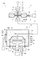
図1は、第1の実施形態に係る液中プラズマ発生装置および液中プラズマ処理装置を例示するための模式断面図である。
なお、図1は、一例として、半導体ウェーハやガラス基板などの被処理物Wを処理する液中プラズマ処理装置100を例示するものである。
図1に示すように、液中プラズマ処理装置100には、液中プラズマ発生装置1と処理部10とが設けられている。
Hereinafter, embodiments will be illustrated with reference to the drawings. In addition, in each drawing, the same code | symbol is attached | subjected to the same component and detailed description is abbreviate | omitted suitably.
[First embodiment]
FIG. 1 is a schematic cross-sectional view for illustrating an in-liquid plasma generator and an in-liquid plasma processing apparatus according to the first embodiment.
In addition, FIG. 1 illustrates the in-liquid
As shown in FIG. 1, the in-liquid
液中プラズマ発生装置1には、共振部2、導波部3、マイクロ波発生部4、プラズマ処理部5、液体供給部6、配管7、配管8が設けられている。
共振部2は、マイクロ波Mを共振させ、後述する減圧部5に共振させたマイクロ波Mを放射する。
共振部2には、環状部2a、強電界発生部2bが設けられている。
環状部2aは、中空の環状を呈し、外周面側には導波部3が設けられている。環状部2aの内部空間と導波部3の内部空間とが連通され、導波部3を介して環状部2aにマイクロ波Mが導入されるようになっている。
The submerged plasma generator 1 is provided with a
The
The
The
強電界発生部2bは、環状部2aの内周面側に設けられた互いに平行な一対の板状体を有している。強電界発生部2bの一対の板状体間に形成される内部空間と環状部2aの内部空間とが連通され、環状部2aの内部空間から強電界発生部2bの内部空間にマイクロ波Mが導入されるようになっている。
また、強電界発生部2bの一対の板状体間をプラズマ処理部5の減圧部5bが貫通している。
ここで、一対の板状体同士の間の寸法は、環状部2aの軸方向の内部空間の寸法よりも短くなっており、電界強度を強くすることができる。また、環状部2aの内部空間から強電界発生部2bの内部空間に導入されたマイクロ波Mを共振させることができるので、さらに電界強度を強くすることができる。この場合、強電界発生部2bの内部空間が強電界発生領域となる。なお、強電界発生部2bは、マイクロ波Mを共振させることで、気泡Bに含まれた気体の絶縁破壊電界強度を超えた電界強度を生じさせる。また、強電界発生部2bによれば、磁場強度を強くすることもできる。そのため、強い電界強度と強い磁場強度とを有するマイクロ波Mを気泡Bを含んだ液体Lに導入することができる。
The strong
Further, the
Here, the dimension between the pair of plate-like bodies is shorter than the dimension of the internal space in the axial direction of the
導波部3は、管状(例えば、角管状)を呈し、その一端は環状部2aの外周面側に設けられ、その他端はマイクロ波発生部4に設けられている。導波部3は、マイクロ波発生部4において発生させたマイクロ波Mを環状部2aの内部空間に向けて導波する。
環状部2a、強電界発生部2b、導波部3は、例えば、アルミニウム合金や銅合金などから形成されるものとすることができる。
The
The
マイクロ波発生部4は、所定の周波数を有するマイクロ波Mを発生させ、導波部3の内部空間に向けて放射する。
発生させるマイクロ波Mの周波数は、例えば、2.45GHzとすることができる。
The
The frequency of the microwave M to be generated can be set to 2.45 GHz, for example.
プラズマ処理部5には、流入部5a、減圧部5b、流出部5cが設けられている。
流入部5aは、管状を呈し、配管7を介して液体供給部6から供給された液体Lを減圧部5bに流入させる。
流出部5cは、管状を呈し、減圧部5bにおいてプラズマ処理された液体Lを配管8に向けて流出させる。
The
The
The
減圧部5bは、液体Lの流速を上昇させることで液体Lの圧力を減圧させて溶存している気体の気泡Bを発生させる、もしくは、気泡Bを発生させやすくする。また、減圧部5bにおいては、後述するマイクロ波Mによる加熱により液体Lを沸騰させて気泡Bを発生させる。
減圧部5bの内部空間の液体Lの流れ方向と垂直な方向における断面積は、流入部5aの内部空間の液体Lの流れ方向と垂直な方向における断面積よりも小さくなっている。そのため、流入部5aから減圧部5bに流入した液体Lの流速を上昇させることができるので、減圧部5bにおける液体Lの圧力を減圧することができる。その結果、減圧部5bにおいて液体L中に気泡Bを発生させることができ、気泡Bを含んだ液体Lに強い電界強度を有するマイクロ波Mを導入することができる。そして、減圧部5bの内部において、気泡Bと導入されたマイクロ波Mとによりプラズマが発生する領域Pが形成されることになる。
また、減圧部5bにおいては、気泡Bを発生させるまでに至らなくても、減圧することによって気泡Bを発生させやすくするだけでもよい。気泡Bを発生させやすくされた液体Lは、導入されたマイクロ波Mの加熱によって、沸騰現象を起こし、気泡Bを容易に発生させることができる。
The
The cross-sectional area in the direction perpendicular to the flow direction of the liquid L in the internal space of the
Further, in the
流入部5a、減圧部5b、流出部5cは、例えば、円管状を呈し、石英などの誘電体から形成されたものとすることができる。
The
ここで、高電圧が印加される金属電極間においてプラズマ処理を行う場合には、金属電極を液体L中に設ける必要がある。そのため、金属電極などが液体Lに触れることで腐食したり、金属電極などが腐食することで液体Lが金属汚染されたりするおそれがある。 Here, when performing plasma treatment between metal electrodes to which a high voltage is applied, it is necessary to provide the metal electrodes in the liquid L. Therefore, there is a possibility that the metal electrode or the like corrodes when it touches the liquid L, or the liquid L or the like corrodes the metal when the metal electrode or the like corrodes.
これに対し、本実施の形態によれば、減圧部5bの外側から内側にマイクロ波Mを導入することができる。すなわち、減圧部5bにより液体Lと共振部2の強電界発生部2bとを離隔させることができるので、強電界発生部2bが液体Lに触れることで腐食したり、強電界発生部2bが腐食することで液体Lが金属汚染されたりすることを抑制することができる。また、後述する微細体が絶縁体であったとしてもプラズマ処理による微細体の生成が可能となる。
On the other hand, according to the present embodiment, the microwave M can be introduced from the outside to the inside of the
液体供給部6は、配管7を介して流入部5aに液体Lを供給する。液体供給部6は、例えば、図示しないタンクや送液ポンプなどを備えたものとすることができる。なお、液体供給部6による送液は、例えば、高低差を利用したものであってもよいし、送液ポンプなどにより圧送されるものであってもよい。
The
また、液体供給部6には図示しない流量制御弁などを適宜設けるようにすることができる。液体供給部6に図示しない流量制御弁などを設けて減圧部5bにおける液体Lの流速(圧力)を制御するようにすれば、気泡Bの発生量を制御することができる。また、プラズマ処理された液体Lの供給の開始、供給の停止、流量の調整などを行うこともできる。この場合、後述する吐出部14に図示しない流量制御弁などを設けるようにすれば、プラズマ処理により生成されたプラズマ生成物が失活してしまうおそれがある。そのため、プラズマ生成物の失活を抑制するという観点からは、液体供給部6に図示しない流量制御弁などを設けるようにすることが好ましい。
The
また、液体供給部6には、液体L中に気体を導入して液体L中に溶存する気体の量を増加させる図示しない気体導入装置などを設けるようにしてもよい。
また、流入部5aの上流側に液体Lに超音波を照射する図示しない超音波発生装置などを設け、超音波発生装置により発生させた気泡を併せて用いるようにしてもよい。
図示しない気体導入装置や超音波発生装置などを設けるようにすれば、プラズマ処理を行う際の気泡量を増加させることができる。
The
Further, an ultrasonic generator (not shown) that irradiates the liquid L with ultrasonic waves may be provided on the upstream side of the
If a gas introduction device, an ultrasonic generator, etc. (not shown) are provided, the amount of bubbles when performing the plasma treatment can be increased.
液体Lは、特に限定されるわけではなく気体を溶存させることができるものであってもよい。この場合、液体Lは、気体を溶解する能力、比重や比熱などの物理的な性質、被処理物Wなどに対する化学的な性質、後述するプラズマ処理により生成される微細体などを考慮して適宜選択することができる。
液体Lとしては、例えば、水などの無機溶剤、アルコールなどの有機溶剤、無機溶剤と有機溶剤との混合液などを例示することができる。
また、液体Lには、気体以外の物質を含ませるようにすることもできる。
また、液体Lには気体が溶存していなくてもよく、液体Lのみで構成されていてもよい。その場合、液体Lを減圧により沸騰させる、もしくは加熱により沸騰させることによって液体L自体が気化して気体となり、液体L中にその気体を内包した気泡Bを発生させることができる。
The liquid L is not particularly limited, and may be a liquid that can dissolve a gas. In this case, the liquid L is appropriately selected in consideration of the ability to dissolve a gas, physical properties such as specific gravity and specific heat, chemical properties with respect to the workpiece W, fine bodies generated by plasma processing described later, and the like. You can choose.
Examples of the liquid L include an inorganic solvent such as water, an organic solvent such as alcohol, a mixed liquid of an inorganic solvent and an organic solvent, and the like.
Further, the liquid L can contain a substance other than gas.
Further, the liquid L may not be dissolved in gas, and may be composed of only the liquid L. In that case, when the liquid L is boiled under reduced pressure or boiled by heating, the liquid L itself is vaporized into a gas, and bubbles B enclosing the gas in the liquid L can be generated.
配管7は、液体供給部6と流入部5aとの間に設けられ、液体供給部6から流入部5aに向けて液体Lを流通させる。
配管8は、流出部5cと処理部10の吐出部14との間に設けられ、流出部5cから吐出部14に向けてプラズマ処理された液体Lを流通させる。
配管7、配管8の材料は特に限定されないが、少なくとも配管8の材料は後述するプラズマ生成物が失活し難い材料とすることが好ましい。配管8の材料は、例えば、フッ素樹脂(例えば、ポリテトラフルオロエチレン)などとすることができる。
なお、配管7、配管8は必ずしも設ける必要はなく、プラズマ処理部5、液体供給部6、処理部10などの配置に応じて適宜設けるようにすることができる。
The
The
The material of the
The
処理部10には、処理容器12、載置部13、吐出部14、遮蔽部15が設けられている。
処理容器12は、プラズマ処理された液体Lに対する耐性の高い有機材料などから形成されるようにすることができる。処理容器12は、例えば、フッ素樹脂(例えば、ポリテトラフルオロエチレン)などから形成されるようにすることができる。また、処理容器12は、液体Lなどが外部に漏れないように気密構造とすることができる。
The
The
処理容器12の側壁には、被処理物W(例えば、ウェーハやガラス基板など)の搬入搬出を行うための開口部12aが設けられ、開口部12aを気密に開閉可能な開閉扉12bが設けられている。開閉扉12bは、開閉機構12cにより開閉動作するようになっている。また、開口部12aを閉鎖する場合には、開閉扉12bに設けられたシール部12dを処理容器12の側壁面に押し付けることで開口部12aを気密に閉鎖できるようになっている。
また、処理容器12の底部には、処理容器12内の排気および使用済みの液体Lなどを排出させるための排出口12eが設けられている。排出口12eには、排出された排気および使用済みの液体Lなどを処理する図示しない処理装置などを接続することができる。
The side wall of the
Further, an
処理容器12の内部には、載置部13が設けられている。
被処理物Wを載置、保持して回転させる載置部13には、載置台22、駆動部23が設けられている。
載置台22は円板状を呈し、一方の主面が被処理物Wを載置する載置面22aとなっている。また、載置台22にはバキュームチャックなどの図示しない保持部が設けられており、載置された被処理物Wを保持することができるようになっている。なお、載置面22aの周縁に被処理物Wの周端を支持する図示しない支持部を設けて、被処理物Wの周端を支持することで載置面22aに載置された被処理物Wが保持されるようにしてもよい。
A
A mounting table 22 and a driving
The mounting table 22 has a disk shape, and one main surface is a mounting
載置台22の他方の主面の中心には回転軸22bが設けられている。回転軸22bは駆動部23と接続され、載置面22aに保持された被処理物Wを回転軸22b周りに回転させることができるようになっている。また、回転軸22bが処理容器12の底部を挿通する部分にはシール部26が設けられており、使用済みの液体Lなどが処理容器12外に漏れ出ないようになっている。
駆動部23は、例えば、サーボモータなどの制御モータなどから構成され、載置台22を回転軸22b周りに回転させるとともに、回転数、起動、停止などの制御ができるようになっている。
A
The
吐出部14の一端に設けられた吐出口14aは被処理物Wの処理面Waに向けて設けられ、吐出部14の他端には配管8が接続されている。吐出部14は、載置台22の載置面22aに保持された被処理物Wの処理面Waにプラズマ処理された液体Lを供給する。また、載置面22aに対する吐出口14aの位置(プラズマ処理された液体Lの供給位置)を変化させる図示しない移動部を適宜設けるようにすることができる。
A
吐出部14の少なくとも液体Lと接触する部分は、プラズマ処理された液体Lに対する耐性が高く、且つ、プラズマ生成物が失活し難い材料から形成されるようにすることが好ましい。そのような材料としては、例えば、フッ素樹脂(例えば、ポリテトラフルオロエチレン)などを例示することができる。
なお、被処理物Wに対する液体Lの供給位置は図1に例示をしたものに限定されるわけではなく適宜変更することができる。
It is preferable that at least a portion of the
In addition, the supply position of the liquid L with respect to the to-be-processed object W is not necessarily limited to what was illustrated in FIG. 1, but can be changed suitably.
遮蔽部15には、カップ体24、駆動部25が設けられている。
カップ体24は、載置台22の外周方向を覆うように設けられている。
カップ体24には、基部24a、カバー24b、昇降軸24cが設けられている。
基部24aは、円管状を呈し、上面および下面が開口されている。
カバー24bは、基部24aの上端に設けられている。カバー24bは傾斜面となっており、その上端が基部24aの中心に近づく方向に傾斜している。この様な形態を有するカバー24bとすることで、被処理物Wの処理面Waに供給された液体Lがカバー24bの上面から飛散することを抑制することができる。また、カバー24bの上面は開口されており、カバー24bの開口が被処理物Wよりも大きくなっている。
The shielding
The
The
The
The
基部24aの下端には昇降軸24cの一端が接続され、昇降軸24cの他端は駆動部25に接続されている。また、昇降軸24cが処理容器12の底部を挿通する部分にはシール部27が設けられており、使用済みの液体Lなどが処理容器12の外部に漏れ出ないようになっている。
駆動部25は、例えば、サーボモータなどの制御モータや空圧シリンダーなどから構成され、昇降軸24cを介して基部24a、カバー24bを昇降させることができるようになっている。この場合、被処理物Wの処理面Waに供給された液体Lがカバー24bの上面から飛散するのを抑制することができる位置を上昇端とし、載置台22への被処理物Wの載置が容易となる位置を下降端とすることができる。なお、上昇端、下降端の位置は、図示しない検出器によりカップ体24の昇降位置を検出することで制御することができる。
One end of an elevating
The
なお、処理容器12に設けられた要素、回転軸22b、駆動部23、遮蔽部15に設けられた要素などは必ずしも必要ではなく、必要に応じて適宜設けるようにすることができる。
In addition, the element provided in the
次に、液中プラズマ処理装置100の作用について例示する。
まず、液中プラズマ発生装置1の作用について例示する。
液体供給部6から配管7を介してプラズマ処理部5の流入部5aに液体Lが供給される。前述したように、流入部5aから減圧部5bに液体Lが流入すると、流入した液体Lの流速が上昇する。そのため、液体Lの圧力が低下することで沸騰現象が生じ、液体L自体が気化した気体や液体Lに溶存していた気体を内包する気泡Bが発生する。
または、液体Lの圧力が低下することで沸騰現象が生じやすくなり、後述する加熱による気泡Bを発生させやすくすることができる。
Next, the operation of the in-liquid
First, the operation of the in-liquid plasma generator 1 will be illustrated.
The liquid L is supplied from the
Or it becomes easy to produce a boiling phenomenon because the pressure of the liquid L falls, and it can make it easy to generate the bubble B by the heating mentioned later.
一方、マイクロ波発生部4から導波部3を介して共振部2の環状部2aにマイクロ波Mが導入される。環状部2aに導入されたマイクロ波Mは、強電界発生部2bにおいて共振されるので強い電界強度を有するマイクロ波Mとなる。
共振部2において電界強度が強められたマイクロ波Mは、石英などの誘電体から形成された減圧部5bの内部に導入される。
ここで、気泡Bが減圧部5bにおいて未だ発生していなくても、マイクロ波Mが減圧部5bに導入されることで、減圧部5bにおける液体Lが加熱されて沸騰現象が生じ、液体L中に気泡Bが発生する。
そして、単に液体中にマイクロ波Mを導入してもプラズマを発生させることはできないが、液体Lには気泡Bが含まれているので気泡B中においてプラズマを発生させることができる。この場合、減圧部5bの圧力が減圧されていることになるので、気泡B中の圧力を低下させることができる。そのため、プラズマ発生の容易化を図ることができる。
On the other hand, the microwave M is introduced from the
The microwave M whose electric field strength is increased in the
Here, even if the bubble B has not yet occurred in the
And even if the microwave M is simply introduced into the liquid, plasma cannot be generated. However, since the liquid L contains the bubbles B, the plasma can be generated in the bubbles B. In this case, since the pressure of the
そして、発生したプラズマによりプラズマ処理が行われる。
例えば、気泡B中に含まれる蒸気や気体、あるいは気泡Bと液体Lとの界面にある液体Lや液体Lに含まれている物質などがプラズマによって励起、活性化されて中性活性種、イオンや電子などの荷電粒子などのプラズマ生成物が生成される。
また、減圧部5bの内部に所望の材料から形成された部材を設けるようにすれば、荷電粒子を部材に衝突させることができるので部材の成分からなるナノ粒子などの微細体を生成することもできる。すなわち、減圧部5bの内部に設けられた物質をスパッタリングすることで、ナノ粒子などの微細体を生成することができる。なお、所望の材料から形成された減圧部5b自体の内壁をスパッタリングすることで、ナノ粒子などの微細体を生成することもできる。
また、液体Lに含まれている物質や液体L自体からナノ粒子などの微細体を生成することもできる。例えば、液体Lに含まれている有機物の炭素からカーボンナノファイバーなどの炭素系の微細体を生成することもできる。
また、生成されたプラズマ生成物により液体Lに含まれている有機物、有害物質、細菌類などの物質を分解することもできる。
Then, plasma processing is performed by the generated plasma.
For example, the vapor or gas contained in the bubble B, or the liquid L or the substance contained in the liquid L at the interface between the bubble B and the liquid L are excited and activated by the plasma to be neutral active species, ions Plasma products such as charged particles such as electrons and electrons are generated.
Further, if a member made of a desired material is provided inside the
Moreover, fine bodies such as nanoparticles can be generated from the substances contained in the liquid L and the liquid L itself. For example, carbon-based fine bodies such as carbon nanofibers can be generated from organic carbon contained in the liquid L.
Moreover, organic substances, harmful substances, bacteria, and other substances contained in the liquid L can be decomposed by the generated plasma product.
このようにして生成されたプラズマ生成物や微細体は液体L中に拡散され、プラズマ処理された液体Lが生成される。また、生成されたプラズマ生成物により液体Lに含まれている有機物、有害物質、細菌類などの物質を分解する場合には、有機物、有害物質、細菌類などの物質が分解された液体Lがプラズマ処理された液体Lとなる。プラズマ処理された液体Lは、流出部5c、配管8を介して吐出部14に供給される。
The plasma products and fine bodies thus generated are diffused into the liquid L, and the plasma-treated liquid L is generated. In addition, when decomposing substances such as organic substances, toxic substances, and bacteria contained in the liquid L by the generated plasma product, the liquid L obtained by decomposing substances such as organic substances, toxic substances, and bacteria is obtained. The liquid L is plasma-treated. The plasma-treated liquid L is supplied to the
次に、処理部10の作用について例示する。
まず、駆動部25により、基部24a、カバー24bが下降端まで下降する。
次に、開閉機構12cにより開閉扉12bが開けられ、開口部12aを介して図示しない搬入搬出装置などにより被処理物Wが処理容器12の内部に搬入される。搬入された被処理物Wは載置台22の載置面22aに載置される。載置面22aに載置された被処理物Wは、バキュームチャックなどの図示しない保持部により保持される。なお、載置面22aの周縁に被処理物Wの周端を支持する図示しない支持部が設けられている場合には、図示しない支持部により被処理物Wの周端が支持されることで、載置面22aに載置された被処理物Wが保持される。
被処理物Wが保持されることで、載置台22が回転した際に被処理物Wの位置がずれることを抑制することができる。
Next, the operation of the
First, the
Next, the opening /
By holding the workpiece W, it is possible to prevent the position of the workpiece W from shifting when the mounting table 22 rotates.
次に、開閉機構12cにより開閉扉12bを閉め、駆動部25により、基部24a、カバー24bを上昇端まで上昇させる。
次に、駆動部23により回転軸22bを回転させることで、載置面22aに保持された被処理物Wを所定の回転数で回転させる。
なお、一例として、回転させた被処理物Wの処理面Waにプラズマ処理された液体Lを供給する場合を例示するが、プラズマ処理された液体Lが処理面Waに供給された被処理物Wを回転させることもできる。
Next, the opening /
Next, the to-be-processed object W hold | maintained on the mounting
As an example, a case where the plasma-treated liquid L is supplied to the processing surface Wa of the rotated workpiece W is illustrated, but the workpiece W supplied with the plasma-treated liquid L is supplied to the processing surface Wa. Can also be rotated.
次に、吐出部14の吐出口14aから被処理物Wの処理面Waにプラズマ処理された液体Lが供給される。この場合、プラズマ処理された液体Lの供給の開始、供給の停止、流量の調整などは液体供給部6に設けられた図示しない流量制御弁などにより行うことができる。
処理面Waに供給されたプラズマ処理された液体Lは、被処理物Wを回転させることで処理面Waの全域に行きわたり所望の処理が行われる。
例えば、プラズマ生成物を含む液体Lを用いて処理面Waに付着している有機物などを除去するようにすることができる。
また、例えば、微細体を含む液体Lを用いて処理面Waに微細体を付着させるようにすることができる。
Next, the plasma-processed liquid L is supplied from the
The plasma-processed liquid L supplied to the processing surface Wa reaches the entire surface of the processing surface Wa by rotating the workpiece W and is subjected to a desired processing.
For example, the organic substance adhering to the processing surface Wa can be removed using the liquid L containing the plasma product.
Further, for example, the fine body can be attached to the processing surface Wa using the liquid L containing the fine body.
使用済みの液体Lは遠心力により被処理物Wの径外方向に排出される。被処理物Wの径外方向に排出された使用済みの液体Lは、カップ体24の基部24a、カバー24bにより飛散が抑制され、処理容器12の底部に集められる。処理容器12の底部に集められた使用済みの液体Lは、排出口12eから排出される。
The used liquid L is discharged out of the diameter of the workpiece W by centrifugal force. The used liquid L discharged in the radially outward direction of the workpiece W is prevented from being scattered by the base 24 a and the
処理面Waに残留した液体Lは、いわゆるスピン乾燥を行うことで蒸散させることができる。
なお、図示しない吐出部からリンス液や有機溶媒を処理面Waにさらに供給することもできる。この場合、有機溶媒と処理面Waに残留している液体Lとを置換したり、より蒸散させやすい混合液を形成させたりすることで、ウォータマークなどが抑制された乾燥を行うこともできる。
The liquid L remaining on the processing surface Wa can be evaporated by performing so-called spin drying.
Note that a rinsing liquid or an organic solvent may be further supplied to the processing surface Wa from a discharge unit (not shown). In this case, the organic solvent and the liquid L remaining on the processing surface Wa can be replaced, or a mixture liquid that is more easily evaporated can be formed to perform drying with the watermark suppressed.
次に、被処理物Wの回転を止め、駆動部25により、基部24a、カバー24bを下降端まで下降させる。そして、開閉機構12cにより開閉扉12bを開け、被処理物Wを図示しない搬入搬出装置などにより搬出する。その後、必要に応じて前述した動作を繰り返すことで被処理物Wの処理を連続的に行うことができる。
Next, the rotation of the workpiece W is stopped, and the
本実施の形態によれば、高電圧が印加される金属電極を液体L中に設けたり、する必要がない。すなわち、減圧部5bにより液体Lと強電界発生部2bとを離隔させることができるので、液体Lの金属汚染を抑制することができる。例えば、強電界発生部2bが液体Lに触れることで腐食したり、強電界発生部2bが腐食することで液体Lが金属汚染されたりすることを抑制することができる。そのため、例えば、プラズマ処理された液体Lを半導体装置などの電子デバイスの洗浄などに用いる場合であっても金属汚染などの発生を抑制することができる。
また、被処理物Wの処理面Waに微細体を付着させる場合には、金属不純物の混入を抑制することができる。
また、強い電界強度と強い磁場強度とを有するマイクロ波Mを気泡Bを含んだ液体Lに導入することができる。そのため、低パワーでもプラズマの放電着火、プラズマの維持がしやすくなり、プラズマ処理の効率を向上させることができる。
According to the present embodiment, it is not necessary to provide the metal electrode to which the high voltage is applied in the liquid L. That is, since the liquid L and the strong
In addition, when a fine body is attached to the processing surface Wa of the workpiece W, mixing of metal impurities can be suppressed.
Further, the microwave M having a strong electric field strength and a strong magnetic field strength can be introduced into the liquid L containing the bubbles B. As a result, plasma discharge ignition and plasma can be easily maintained even at low power, and the efficiency of plasma processing can be improved.
[第2の実施形態]
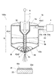
図2は、第2の実施形態に係る液中プラズマ発生装置および液中プラズマ処理装置を例示するための模式断面図である。
なお、図2は、一例として、半導体ウェーハやガラス基板などの被処理物Wを処理する液中プラズマ処理装置100aを例示するものである。
図2に示すように、液中プラズマ処理装置100aには、液中プラズマ発生装置1aと処理部10aとが設けられている。
[Second Embodiment]
FIG. 2 is a schematic cross-sectional view for illustrating an in-liquid plasma generator and an in-liquid plasma processing apparatus according to the second embodiment.
FIG. 2 illustrates, as an example, an in-liquid
As shown in FIG. 2, the in-liquid
液中プラズマ発生装置1aには、共振部32、マイクロ波発生部4、プラズマ処理部5、液体供給部6、配管7、配管8が設けられている。
共振部32には、導波部32a、整合器32b、定在波形成部32cが設けられている。
導波部32aは、管状(例えば、角管状)を呈し、その一端はマイクロ波発生部4に設けられている。導波部32aは、マイクロ波発生部4において発生させたマイクロ波Mを導波する。
導波部32aは、例えば、アルミニウム合金や銅合金などから形成されるものとすることができる。
The submerged
The resonating
The
The
導波部32aには、導波部32aの軸方向に直交する方向にプラズマ処理部5の減圧部5bが貫通している。なお、減圧部5bは必ずしも導波部32aを貫通している必要はなく、導波部32aにスロットを設けこのスロットに面する位置に減圧部5bを設けるようにすることもできる。
整合器32bは、プラズマ処理部5とマイクロ波発生部4との間に設けられ、マイクロ波Mのインピーダンスマッチングを行う。整合器32bは、例えば、スタブチューナなどとすることができる。
The
The matching
定在波形成部32cには、導波部32aの終端側の内部に設けられた可動板32c1と、可動板32c1の位置を導波部32aの軸方向に変化させる移動部32c2とが設けられている。可動板32c1は、導波部32aの内部空間を導波されてきたマイクロ波Mを反射させることで共振させるとともに定在波を形成させる。また、可動板32c1の位置を導波部32aの軸方向に変化させることで定在波の最大電界強度位置を変化させる。この場合、移動部32c2は、可動板32c1の位置を変化させることで導波部32aの内部に形成された定在波の最大電界強度位置が、マイクロ波Mを放射する位置となるようにする。すなわち、移動部32c2は、可動板32c1の位置を変化させることで減圧部5bの位置が定在波の最大電界強度位置となるようにする。なお、最大電界強度位置において発生する電界強度は、気泡Bに含まれた気体の絶縁破壊電界強度を超えるものとなっている。
なお、導波部32aの内部に形成された定在波の最大電界強度位置が、マイクロ波を放射する位置となるように、定在波形成部32cを予め調整すれば、移動部32c2は設けなくてもよく、可動板32c1は調整後には位置を固定するようにしてもよい。導波部32aの内部に形成された定在波の最大電界強度位置がマイクロ波を放射する位置となるように、可動板32c1の位置を予め設計するようにすれば、可動板32c1は移動するものではなく共振部32に固定されたものであってもよい。
The standing
If the standing
この様に、導波部32a内部における減圧部5bの近傍が強電界発生領域となる。そのため、強電界発生領域における異常放電を抑制するために、強電界発生領域の減圧部5b以外の部分には、気泡Bに含まれた気体以上の絶縁破壊電界強度を有した図示しない絶縁部を設けるようにすることもできる。
また、処理部10aには、吐出部14、載置台22が設けられている。
In this way, the vicinity of the
The
次に、液中プラズマ処理装置100aの作用について図2を参照して例示する。
まず、液中プラズマ発生装置1aの作用について例示する。
液体供給部6から配管7を介してプラズマ処理部5の流入部5aに液体Lが供給される。前述したように、流入部5aから減圧部5bに液体Lが流入すると、流入した液体Lの流速が上昇する。そのため、液体Lの圧力が低下することで沸騰現象が生じ、液体Lに溶存していた気体、もしくは液体L自体が気化した気体を内包する気泡Bが発生する。
Next, the operation of the in-liquid
First, the operation of the in-
The liquid L is supplied from the
一方、マイクロ波発生部4から導波部32aの内部空間にマイクロ波Mが放射される。導波部32aの内部空間に放射されたマイクロ波Mは、整合器32bによりインピーダンスマッチングが行われるとともに、定在波形成部32cにより共振されるとともに定在波が形成される。この際、減圧部5bの位置が定在波の最大電界強度位置となるように可動板32c1の位置が移動部32c2により制御される。
On the other hand, the microwave M is radiated from the
定在波形成部32cにより電界強度が強められたマイクロ波Mは、石英などの誘電体から形成された減圧部5bの内部に導入される。ここで、単に液体中にマイクロ波Mを導入してもプラズマを発生させることはできないが、液体Lには気泡Bが含まれているので気泡B中においてプラズマを発生させることができる。この場合、減圧部5bの圧力が減圧されていることになるので、気泡B中の圧力を低下させることができる。そのため、プラズマ発生の容易化を図ることができる。
The microwave M whose electric field strength is strengthened by the standing
そして、前述したものと同様に、発生したプラズマによりプラズマ生成物が生成される。
また、減圧部5bの内部に所望の材料から形成された部材を設けるようにすれば、荷電粒子を部材に衝突させることができるので部材の成分からなるナノ粒子などの微細体を生成することもできる。
また、減圧部5bを所望の材料で形成し、減圧部5b自体の内壁をスパッタリングすることで、ナノ粒子などの微細体を生成することもできる。
また、液体Lに含まれている物質や液体L自体からナノ粒子などの微細体を生成することもできる。
また、生成されたプラズマ生成物により液体Lに含まれている有機物、有害物質、細菌類などの物質を分解することもできる。
And a plasma product is produced | generated by the generated plasma similarly to what was mentioned above.
Further, if a member made of a desired material is provided inside the
Moreover, fine bodies, such as a nanoparticle, can also be produced | generated by forming the
Moreover, fine bodies such as nanoparticles can be generated from the substances contained in the liquid L and the liquid L itself.
Moreover, organic substances, harmful substances, bacteria, and other substances contained in the liquid L can be decomposed by the generated plasma product.
このようにして生成されたプラズマ生成物や微細体は液体L中に拡散され、プラズマ処理された液体Lが生成される。また、生成されたプラズマ生成物により液体Lに含まれている有機物、有害物質、細菌類などの物質を分解する場合には、有機物、有害物質、細菌類などの物質が分解された液体Lがプラズマ処理された液体Lとなる。プラズマ処理された液体Lは、流出部5c、配管8を介して吐出部14に供給される。
The plasma products and fine bodies thus generated are diffused into the liquid L, and the plasma-treated liquid L is generated. In addition, when decomposing substances such as organic substances, toxic substances, and bacteria contained in the liquid L by the generated plasma product, the liquid L obtained by decomposing substances such as organic substances, toxic substances, and bacteria is obtained. The liquid L is plasma-treated. The plasma-treated liquid L is supplied to the
次に、処理部10aの作用について例示する。
まず、図示しない搬入搬出装置などにより被処理物Wが搬入される。搬入された被処理物Wは載置台22の載置面22aに載置される。載置面22aに載置された被処理物Wは、バキュームチャックなどの図示しない保持部により保持される。なお、載置面22aの周縁に被処理物Wの周端を支持する図示しない支持部が設けられている場合には、図示しない支持部により被処理物Wの周端が支持されることで、載置面22aに載置された被処理物Wが保持される。
Next, the operation of the
First, the workpiece W is loaded by a loading / unloading device (not shown). The loaded workpiece W is placed on the
次に、吐出部14の吐出口14aから被処理物Wの処理面Waにプラズマ処理された液体Lが供給される。この場合、プラズマ処理された液体Lの供給の開始、供給の停止、流量の調整などは液体供給部6に設けられた図示しない流量制御弁などにより行うことができる。
処理面Waに供給されたプラズマ処理された液体Lは、処理面Waの全域に行きわたり所望の処理が行われる。
例えば、プラズマ生成物を含む液体Lを用いて処理面Waに付着している有機物などを除去するようにすることができる。
また、例えば、微細体を含む液体Lを用いて処理面Waに微細体を付着させるようにすることができる。
使用済みの液体Lは被処理物Wの径外方向に排出される。被処理物Wの径外方向に排出された使用済みの液体Lは、図示しない回収部により回収される。
Next, the plasma-processed liquid L is supplied from the
The plasma-processed liquid L supplied to the processing surface Wa reaches the entire surface of the processing surface Wa and is subjected to a desired processing.
For example, the organic substance adhering to the processing surface Wa can be removed using the liquid L containing the plasma product.
Further, for example, the fine body can be attached to the processing surface Wa using the liquid L containing the fine body.
The used liquid L is discharged in the radially outward direction of the workpiece W. The used liquid L discharged in the radially outward direction of the workpiece W is recovered by a recovery unit (not shown).
なお、図示しない吐出部からリンス液や有機溶媒を処理面Waにさらに供給することもできる。この場合、有機溶媒と処理面Waに残留している液体Lとを置換したり、より蒸散させやすい混合液を形成させたりすることで、ウォータマークなどが抑制された乾燥を行うこともできる。
次に、被処理物Wを図示しない搬入搬出装置などにより搬出する。その後、必要に応じて前述した動作を繰り返すことで被処理物Wの処理を連続的に行うことができる。
Note that a rinsing liquid or an organic solvent may be further supplied to the processing surface Wa from a discharge unit (not shown). In this case, the organic solvent and the liquid L remaining on the processing surface Wa can be replaced, or a mixture liquid that is more easily evaporated can be formed to perform drying with the watermark suppressed.
Next, the workpiece W is unloaded by a loading / unloading device (not shown). Thereafter, the processing of the workpiece W can be continuously performed by repeating the above-described operation as necessary.
本実施の形態によれば、高電圧が印加される金属電極を液体L中に設けたり、マイクロ波Mの導入部を液体L中や液面の近傍に設けたりする必要がない。すなわち、減圧部5bにより液体Lと定在波形成部32cとを離隔させることができるので、液体Lの金属汚染を抑制することができる。例えば、導波部32aなどが液体Lに触れることで腐食したり、導波部32aなどが腐食することで液体Lが金属汚染されたりすることを抑制することができる。
そのため、例えば、プラズマ処理された液体Lを半導体装置などの電子デバイスの洗浄などに用いる場合であっても金属汚染などの発生を抑制することができる。
また、被処理物Wの処理面Waに微細体を付着させる場合には、不純物の混入を抑制することができる。
また、強い電界強度と強い磁場強度とを有するマイクロ波Mを気泡Bを含んだ液体Lに導入することができる。そのため、プラズマ処理の効率を向上させることができる。
According to the present embodiment, it is not necessary to provide a metal electrode to which a high voltage is applied in the liquid L, or to provide an introduction part of the microwave M in the liquid L or in the vicinity of the liquid surface. That is, since the liquid L and the standing
Therefore, for example, even when the plasma-treated liquid L is used for cleaning an electronic device such as a semiconductor device, the occurrence of metal contamination can be suppressed.
In addition, when a fine object is attached to the processing surface Wa of the workpiece W, it is possible to suppress mixing of impurities.
Further, the microwave M having a strong electric field strength and a strong magnetic field strength can be introduced into the liquid L containing the bubbles B. Therefore, the efficiency of plasma processing can be improved.
[第3の実施形態]
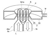
図3は、第3の実施形態に係る液中プラズマ発生装置および液中プラズマ処理装置を例示するための模式断面図である。
なお、図3は、一例として、半導体ウェーハやガラス基板などの被処理物Wを処理する液中プラズマ処理装置100bを例示するものである。
図3に示すように、液中プラズマ処理装置100bには、液中プラズマ発生装置1bと処理部としての載置台22とが設けられている。
[Third embodiment]
FIG. 3 is a schematic cross-sectional view for illustrating an in-liquid plasma generator and an in-liquid plasma processing apparatus according to the third embodiment.
FIG. 3 illustrates, as an example, an in-liquid plasma processing apparatus 100b that processes a workpiece W such as a semiconductor wafer or a glass substrate.
As shown in FIG. 3, the in-liquid plasma processing apparatus 100b is provided with an in-
液中プラズマ発生装置1bには、共振部としての強電界発生部42a、導波部43、マイクロ波発生部4、プラズマ処理部35、液体供給部6、配管7が設けられている。
なお、図3中のEは、発生する電界を表している。
強電界発生部42aは、筒状(例えば、円筒状)を呈し、軸方向の端面が塞がれている。また、強電界発生部42aの中央部分にはプラズマ処理部35が貫通するようにして設けられている。強電界発生部42aのプラズマ処理部35が貫通している部分には、マイクロ波Mを遮蔽する遮蔽部42a1が設けられている。減圧部5bの流出側先端近傍には遮蔽部42a1が設けられておらず、この部分がマイクロ波Mを放射する放射部42a2となる。強電界発生部42aにおいて共振されたマイクロ波Mは、放射部42a2を介して減圧部5bに向けて放射される。
The in-
In addition, E in FIG. 3 represents the electric field which generate | occur | produces.
The strong electric
また、強電界発生部42aの軸方向の寸法Hは、マイクロ波Mの波長の約1/2とされている。この寸法Hは、マイクロ波Mの共振を起こさせることができるように、調整により決定されるものである。そのため、内部導体43cのアンテナとして機能する部分43c1から強電界発生部42aの内部空間に放射されたマイクロ波Mを共振させることができる。なお、強電界発生部42aにおいて発生する電界強度は、気泡Bに含まれた気体の絶縁破壊電界強度を超えるものとなっている。
Further, the dimension H in the axial direction of the strong
導波部43には、外部導体43a、誘電体部43b、内部導体43cが設けられている。
外部導体43aは、一端が強電界発生部42aに接続され、他端がマイクロ波発生部4に接続されている。
誘電体部43bは、外部導体43aの内部に設けられ、外部導体43aと内部導体43cとを絶縁する。
The
One end of the
The
内部導体43cは、一端が強電界発生部42aに接続され、他端がマイクロ波発生部4に接続されている。また、強電界発生部42aの内部において誘電体部43bから内部導体43cが突出している部分43c1がアンテナとして機能する。
One end of the
プラズマ処理部35には、流入部5a、減圧部5b、吐出口5cが設けられている。
減圧部5bの流出側先端部分は流路断面積が漸減するようになっており、流出側先端が吐出口5cとなっている。
また、減圧部5bの流出側先端近傍、すなわち、放射部42a2が設けられている部分の近傍は強電界発生領域となるので、強電界発生領域の減圧部5b以外の部分には、気泡Bに含まれた気体以上の絶縁破壊電界強度を有した絶縁部36を設けるようにすることができる。絶縁部36を設けるようにすれば、強電界発生領域における異常放電を抑制することができる。絶縁破壊電界強度の高い材料としては、例えば、石英などを例示することができる。
The
The flow passage cross-sectional area gradually decreases at the outflow side front end portion of the
Further, the vicinity of the outflow side tip of the
次に、液中プラズマ処理装置100bの作用について例示する。
まず、液中プラズマ発生装置1bの作用について例示する。
液体供給部6から配管7を介してプラズマ処理部35の流入部5aに液体Lが供給される。前述したように、流入部5aから減圧部5bに液体Lが流入すると、流入した液体Lの流速が上昇する。そのため、液体Lの圧力が低下することで沸騰現象が生じ、液体Lに溶存していた気体、もしくは液体L自体が気化した気体を内包する気泡Bが発生する。
Next, the operation of the in-liquid plasma processing apparatus 100b will be illustrated.
First, the operation of the in-
The liquid L is supplied from the
一方、マイクロ波発生部4から導波部43の内部導体43cにマイクロ波Mが放射される。内部導体43cに放射されたマイクロ波Mは、内部導体43cのアンテナとして機能する部分43c1から強電界発生部42aの内部空間に放射される。強電界発生部42aの内部空間に放射されたマイクロ波Mは、強電界発生部42aにおいて共振されるので強い電界強度を有するマイクロ波Mとなる。
On the other hand, the microwave M is radiated from the
強電界発生部42aにおいて電界強度が強められたマイクロ波Mは、放射部42a2を介して石英などの誘電体から形成された減圧部5bの内部に導入される。ここで、単に液体中にマイクロ波Mを導入してもプラズマを発生させることはできないが、液体Lには気泡Bが含まれているので気泡B中においてプラズマを発生させることができる。この場合、減圧部5bの圧力が減圧されていることになるので、気泡B中の圧力を低下させることができる。そのため、プラズマ発生の容易化を図ることができる。
The microwave M whose electric field strength has been strengthened in the strong electric
そして、前述したものと同様に、発生したプラズマによりプラズマ生成物が生成される。
また、減圧部5bの内部に所望の材料から形成された部材を設けるようにすれば、荷電粒子を部材に衝突させることができるので部材の成分からなるナノ粒子などの微細体を生成することもできる。
また、減圧部5bを所望の材料で形成し、減圧部5b自体の内壁をスパッタリングすることで、ナノ粒子などの微細体を生成することもできる。
And a plasma product is produced | generated by the generated plasma similarly to what was mentioned above.
Further, if a member made of a desired material is provided inside the
Moreover, fine bodies, such as a nanoparticle, can also be produced | generated by forming the
また、液体Lに含まれている物質や液体L自体からナノ粒子などの微細体を生成することもできる。
また、生成されたプラズマ生成物により液体Lに含まれている有機物、有害物質、細菌類などの物質を分解することもできる。
Moreover, fine bodies such as nanoparticles can be generated from the substances contained in the liquid L and the liquid L itself.
Moreover, organic substances, harmful substances, bacteria, and other substances contained in the liquid L can be decomposed by the generated plasma product.
このようにして生成されたプラズマ生成物や微細体は液体L中に拡散され、プラズマ処理された液体Lが生成される。また、生成されたプラズマ生成物により液体Lに含まれている有機物、有害物質、細菌類などの物質を分解する場合には、有機物、有害物質、細菌類などの物質が分解された液体Lがプラズマ処理された液体Lとなる。プラズマ処理された液体Lは、吐出口5cから被処理物Wの処理面Waに向けて吐出される。
The plasma products and fine bodies thus generated are diffused into the liquid L, and the plasma-treated liquid L is generated. In addition, when decomposing substances such as organic substances, toxic substances, and bacteria contained in the liquid L by the generated plasma product, the liquid L obtained by decomposing substances such as organic substances, toxic substances, and bacteria is obtained. The liquid L is plasma-treated. The plasma-processed liquid L is discharged from the
次に、載置台22における処理について例示する。
まず、図示しない搬入搬出装置などにより被処理物Wが搬入される。搬入された被処理物Wは載置台22の載置面22aに載置される。載置面22aに載置された被処理物Wは、バキュームチャックなどの図示しない保持部により保持される。なお、載置面22aの周縁に被処理物Wの周端を支持する図示しない支持部が設けられている場合には、図示しない支持部により被処理物Wの周端が支持されることで、載置面22aに載置された被処理物Wが保持される。
Next, the process in the mounting table 22 is illustrated.
First, the workpiece W is loaded by a loading / unloading device (not shown). The loaded workpiece W is placed on the
次に、プラズマ処理部35の吐出口5cから被処理物Wの処理面Waにプラズマ処理された液体Lが供給される。この場合、プラズマ処理された液体Lの供給の開始、供給の停止、流量の調整などは液体供給部6に設けられた図示しない流量制御弁などにより行うことができる。
処理面Waに供給されたプラズマ処理された液体Lは、処理面Waの全域に行きわたり所望の処理が行われる。
例えば、プラズマ生成物を含む液体Lを用いて処理面Waに付着している有機物などを除去するようにすることができる。
また、例えば、微細体を含む液体Lを用いて処理面Waに微細体を付着させるようにすることができる。
また、例えば、被処理物Wの表面改質を行うこともできる。
使用済みの液体Lは被処理物Wの径外方向に排出される。被処理物Wの径外方向に排出された使用済みの液体Lは、図示しない回収部により回収される。
Next, the plasma-processed liquid L is supplied to the processing surface Wa of the workpiece W from the
The plasma-processed liquid L supplied to the processing surface Wa reaches the entire surface of the processing surface Wa and is subjected to a desired processing.
For example, the organic substance adhering to the processing surface Wa can be removed using the liquid L containing the plasma product.
Further, for example, the fine body can be attached to the processing surface Wa using the liquid L containing the fine body.
Further, for example, the surface modification of the workpiece W can be performed.
The used liquid L is discharged in the radially outward direction of the workpiece W. The used liquid L discharged in the radially outward direction of the workpiece W is recovered by a recovery unit (not shown).
なお、図示しない吐出部からリンス液や有機溶媒を処理面Waにさらに供給することもできる。この場合、有機溶媒と処理面Waに残留している液体Lとを置換したり、より蒸散させやすい混合液を形成させたりすることで、ウォータマークなどが抑制された乾燥を行うこともできる。
次に、被処理物Wを図示しない搬入搬出装置などにより搬出する。その後、必要に応じて前述した動作を繰り返すことで被処理物Wの処理を連続的に行うことができる。
Note that a rinsing liquid or an organic solvent may be further supplied to the processing surface Wa from a discharge unit (not shown). In this case, the organic solvent and the liquid L remaining on the processing surface Wa can be replaced, or a mixture liquid that is more easily evaporated can be formed to perform drying with the watermark suppressed.
Next, the workpiece W is unloaded by a loading / unloading device (not shown). Thereafter, the processing of the workpiece W can be continuously performed by repeating the above-described operation as necessary.
本実施の形態によれば、高電圧が印加される金属電極を液体L中に設けたり、マイクロ波Mの導入部を液体L中や液面の近傍に設けたりする必要がない。すなわち、減圧部5bにより液体Lと強電界発生部42aとを離隔させることができるので、液体Lの金属汚染を抑制することができる。例えば、強電界発生部42aが液体Lに触れることで腐食したり、強電界発生部42aが腐食することで液体Lが金属汚染されたりすることを抑制することができる。
そのため、例えば、プラズマ処理された液体Lを半導体装置などの電子デバイスの洗浄などに用いる場合であっても金属汚染などの発生を抑制することができる。
また、被処理物Wの処理面Waに微細体を付着させる場合には、不純物の混入を抑制することができる。
また、強い電界強度と強い磁場強度とを有するマイクロ波Mを気泡Bを含んだ液体Lに導入することができる。そのため、プラズマ処理の効率を向上させることができる。
また、強電界発生領域の減圧部5b以外の部分には、気泡Bに含まれた気体以上の絶縁破壊電界強度を有した絶縁部36が設けられているので、強電界発生領域における異常放電を抑制することができる。
また、プラズマ処理された液体Lを、プラズマ処理の直後に吐出口5cから吐出させて被処理物Wの処理面Waにそのまま供給することができる。そのため、プラズマ処理により生成されたプラズマ生成物が失活する前に処理面Waに供給することができるようになる。
吐出口5cと被処理物Wの処理面Waとの距離は、機械的な制限を受けなければ、可能な限り接近させた方がよい。
また、被処理物Wを吐出口5cに対し一方方向に相対移動させながら、液体Lを被処理物Wの処理面Waに供給し、処理を行うようにしてもよい。
According to the present embodiment, it is not necessary to provide a metal electrode to which a high voltage is applied in the liquid L, or to provide an introduction part of the microwave M in the liquid L or in the vicinity of the liquid surface. That is, since the liquid L and the strong
Therefore, for example, even when the plasma-treated liquid L is used for cleaning an electronic device such as a semiconductor device, the occurrence of metal contamination can be suppressed.
In addition, when a fine object is attached to the processing surface Wa of the workpiece W, it is possible to suppress mixing of impurities.
Further, the microwave M having a strong electric field strength and a strong magnetic field strength can be introduced into the liquid L containing the bubbles B. Therefore, the efficiency of plasma processing can be improved.
In addition, since the insulating
In addition, the plasma-processed liquid L can be discharged from the
The distance between the
Further, the liquid L may be supplied to the processing surface Wa of the workpiece W while the workpiece W is relatively moved in one direction with respect to the
なお、図1〜図3において例示をした処理は、被処理物Wの処理面Waにプラズマ処理された液体Lを供給するものであるがこれに限定されるわけではない。
例えば、プラズマ処理された液体Lを収納した槽に被処理物Wを浸漬させるようにしたものとすることもできる。また、被処理物Wを1つずつ処理する枚葉式とすることもできるし、複数の被処理物Wを同時に処理するバッチ式とすることもできる。
The processing illustrated in FIGS. 1 to 3 supplies the liquid L that has been subjected to plasma processing to the processing surface Wa of the workpiece W, but is not limited thereto.
For example, the workpiece W may be immersed in a tank containing the plasma-treated liquid L. Moreover, it can also be set as the single wafer type which processes the to-be-processed object W one by one, and can also be set as the batch type which processes several to-be-processed objects W simultaneously.
[第4の実施形態]
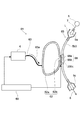
図4は、第4の実施形態に係る液中プラズマ発生装置を例示するための模式断面図である。
液中プラズマ発生装置1cには、共振部2、導波部3、マイクロ波発生部4、プラズマ処理部5、液体供給部6、配管7、配管8、絶縁部36aが設けられている。
液中プラズマ発生装置1cと、前述した液中プラズマ発生装置1とでは、絶縁部36aが設けられていることが異なる。
前述したように、強電界発生部2bの内部空間は強電界発生領域となる。そのため、絶縁部36aは、強電界発生領域である強電界発生部2bの内部空間を埋めるようにして設けられている。
[Fourth Embodiment]
FIG. 4 is a schematic cross-sectional view for illustrating a submerged plasma generation device according to a fourth embodiment.
The submerged
The submerged
As described above, the internal space of the strong
絶縁部36aは、発生した気泡Bに含まれた気体以上の絶縁破壊電界強度を有したものとすることができる。そのため、強電界発生領域における異常放電を抑制することができる。絶縁破壊電界強度の高い材料としては、例えば、石英などを例示することができる。 本実施の形態に係る液中プラズマ発生装置1cによれば、図1において例示をした液中プラズマ発生装置1と同様の効果を奏することができる。
またさらに、強電界発生領域である強電界発生部2bの内部空間における異常放電を抑制することができる。
The insulating
Furthermore, abnormal discharge in the internal space of the strong electric
[第5の実施形態]
ここで、プラズマの発生においては、いわゆる着火がランダムな現象となる。そのため、気泡Bに含まれた気体の絶縁破壊電界強度を超えた電界強度を発生させたとしても直ぐに着火するとは限らない。
この場合、強電界発生領域を大きくすれば、液体Lが強電界発生領域に滞在する時間を長くすることができるので、着火の確率を高めることができる。
しかしながら、強電界発生領域を大きくすれば、共振部の大型化、必要となるマイクロ波エネルギーの増大などを招くことにもなる。
そのため、以下に例示をする液中プラズマ発生装置においては、強電界発生領域における液体Lの流路長が長くなるような減圧部の形状を有したものとされている。なお、プラズマ処理部以外の要素は、図1〜図4などにおいて例示をしたものと同様とすることができるので、それらの例示は適宜省略する。
[Fifth Embodiment]
Here, in the generation of plasma, so-called ignition becomes a random phenomenon. Therefore, even if an electric field strength exceeding the dielectric breakdown electric field strength of the gas contained in the bubble B is generated, it does not always ignite immediately.
In this case, if the strong electric field generation region is enlarged, the time during which the liquid L stays in the strong electric field generation region can be lengthened, so that the probability of ignition can be increased.
However, enlarging the strong electric field generation region leads to an increase in the size of the resonance part and an increase in necessary microwave energy.
Therefore, in the in-liquid plasma generator illustrated below, it has the shape of the pressure reduction part so that the flow path length of the liquid L in a strong electric field generation region becomes long. In addition, since elements other than the plasma processing unit can be the same as those illustrated in FIGS. 1 to 4 and the like, their illustration is omitted as appropriate.
図5は、蛇行形状を有する減圧部を例示するための模式図である。
図5に示すように、プラズマ処理部45には、流入部5a、減圧部5b1、流出部5cが設けられている。
減圧部5b1は、蛇行形状を有し、強電界発生領域200における液体Lの流路長が長くなるようにされている。
蛇行形状を有する減圧部5b1とすれば、液体Lが強電界発生領域200に滞在する時間を長くすることができるので、着火の確率を高めることができる。
FIG. 5 is a schematic diagram for illustrating a decompression unit having a meandering shape.
As shown in FIG. 5, the
The decompression unit 5b1 has a meandering shape, and the flow path length of the liquid L in the strong electric
If the decompression section 5b1 has a meandering shape, the time during which the liquid L stays in the strong electric
図6は、蛇行形状を有する減圧部を共振部に設けた状態を例示するための模式図である。
図6は、強電界発生部2bの互いに平行な一対の板状体を複数回貫通するような減圧部5b1aを有したプラズマ処理部45aを例示するものである。
すなわち、プラズマ処理部45aには、流入部5a、減圧部5b1a、流出部5cが設けられている。そして、蛇行形状を有する減圧部5b1aは、マイクロ波Mを共振させることで生じた強電界発生領域を複数回貫通するように設けられている。
このようなプラズマ処理部45aとすれば、強電界発生領域である強電界発生部2bの内部空間を液体Lが複数回通過するようにすることができる。すなわち、強電界発生領域における液体Lの流路長をその分長くすることができる。そのため、液体Lが強電界発生領域に滞在する実質的な時間を長くすることができるので、着火の確率を高めることができる。
FIG. 6 is a schematic diagram for illustrating a state in which a pressure reducing part having a meandering shape is provided in the resonance part.
FIG. 6 illustrates a
That is, the
With such a
図7は、強電界発生部の内部空間内を蛇行するような減圧部を共振部に設けた状態を例示するための模式図である。なお、図7(a)は平断面図、図7(b)は図7(a)におけるA−A方向矢視断面図である。
図7に示すように、プラズマ処理部45bには、流入部5a、減圧部5b1b、流出部5cが設けられている。そして、蛇行形状を有する減圧部5b1bは強電界発生部2bの内部空間内を蛇行するように設けられている。
このようなプラズマ処理部45bとすれば、強電界発生領域200aである強電界発生部2bの内部空間内における液体Lの流路長を長くすることができる。そのため、液体Lが強電界発生領域200aに滞在する時間を長くすることができるので、着火の確率を高めることができる。
FIG. 7 is a schematic diagram for exemplifying a state in which a decompression unit that meanders in the internal space of the strong electric field generation unit is provided in the resonance unit. 7A is a cross-sectional plan view, and FIG. 7B is a cross-sectional view taken along line AA in FIG. 7A.
As shown in FIG. 7, the
With such a
図8は、螺旋形状を有する減圧部を例示するための模式図である。
図8に示すように、プラズマ処理部55には、流入部5a、減圧部5b2、流出部5cが設けられている。
減圧部5b2は、螺旋形状を有し、強電界発生領域200bにおける液体Lの流路長が長くなるようにされている。
螺旋形状を有する減圧部5b2とすれば、液体Lが強電界発生領域200bに滞在する時間を長くすることができるので、着火の確率を高めることができる。
FIG. 8 is a schematic diagram for illustrating a decompression unit having a spiral shape.
As shown in FIG. 8, the
The decompression unit 5b2 has a spiral shape, and the flow path length of the liquid L in the strong electric
If the decompression unit 5b2 having a spiral shape is used, the time during which the liquid L stays in the strong electric
図9は、強電界発生部の内部空間内に螺旋形状を有する減圧部を設けた場合を例示するための模式図である。なお、図9(a)は平断面図、図9(b)は図9(a)におけるC−C方向矢視断面図である。
図9に示すように、プラズマ処理部55には、流入部5a、減圧部5b2、流出部5cが設けられている。そして、螺旋形状を有する減圧部5b2は強電界発生部2bの内部空間内に設けられている。
このようなプラズマ処理部55とすれば、強電界発生領域200bである強電界発生部2bの内部空間内における液体Lの流路長を長くすることができる。そのため、液体Lが強電界発生領域200baに滞在する時間を長くすることができるので、着火の確率を高めることができる。
FIG. 9 is a schematic diagram for illustrating a case where a decompression unit having a spiral shape is provided in the internal space of the strong electric field generation unit. 9A is a cross-sectional plan view, and FIG. 9B is a cross-sectional view taken along the direction CC in FIG. 9A.
As shown in FIG. 9, the
With such a
図10は、蛇行形状を有する減圧部を共振部に設け、強電界発生領域の減圧部を除いた部分に絶縁体を設けた状態を例示するための模式図である。なお、図10は、図6において例示をしたものに、さらに絶縁部36bを設けた場合である。
図11は、強電界発生部の内部空間内を蛇行するような減圧部を共振部に設け、強電界発生領域の減圧部を除いた部分に絶縁体を設けた状態を例示するための模式図である。なお、図11(a)は平断面図、図11(b)は図11(a)におけるD−D方向矢視断面図である。また、図11は、図7において例示をしたものに、さらに絶縁部36cを設けた場合である。
図12は、強電界発生部の内部空間内に螺旋形状を有する減圧部を設け、強電界発生領域の減圧部を除いた部分に絶縁体を設けた場合を例示するための模式図である。なお、図12(a)は平断面図、図12(b)は図12(a)におけるF−F方向矢視断面図である。なお、図12は、図9において例示をしたものに、さらに絶縁部36dを設けた場合である。
FIG. 10 is a schematic diagram for illustrating a state in which a pressure reducing portion having a meandering shape is provided in the resonance portion, and an insulator is provided in a portion excluding the pressure reducing portion in the strong electric field generation region. FIG. 10 shows a case where an insulating
FIG. 11 is a schematic diagram for exemplifying a state in which a pressure reducing part that meanders in the internal space of the strong electric field generating part is provided in the resonance part, and an insulator is provided in a portion excluding the pressure reducing part in the strong electric field generating region. It is. 11A is a cross-sectional plan view, and FIG. 11B is a cross-sectional view in the DD direction in FIG. 11A. FIG. 11 shows a case where an insulating
FIG. 12 is a schematic diagram for illustrating a case where a decompression unit having a spiral shape is provided in the internal space of the strong electric field generation unit, and an insulator is provided in a portion excluding the decompression unit of the strong electric field generation region. 12A is a cross-sectional plan view, and FIG. 12B is a cross-sectional view taken along the line FF in FIG. 12A. FIG. 12 shows a case where an insulating
前述したように、強電界発生部2bの内部空間は強電界発生領域となる。そのため、絶縁部36b、36c、36dは、強電界発生領域である強電界発生部2bの内部空間を埋めるようにして設けられている。
絶縁部36b、36c、36dは、それぞれの減圧部以上の絶縁破壊電界強度を有したものとすることができる。そのため、強電界発生領域における異常放電を抑制することができる。絶縁破壊電界強度の高い材料としては、例えば、石英などを例示することができる。
なお、図5〜図12において例示をした液中プラズマ発生装置の基本的な作用は、図1において例示をした液中プラズマ発生装置1と同様とすることができるので、詳細な説明は省略する。
As described above, the internal space of the strong
The insulating
The basic operation of the submerged plasma generator illustrated in FIGS. 5 to 12 can be the same as that of the submerged plasma generator 1 illustrated in FIG. .
本実施の形態に係る液中プラズマ発生装置によれば、図1において例示をした液中プラズマ発生装置1と同様の効果を奏することができる。
またさらに、液体Lが強電界発生領域に滞在する時間を長くすることができるので、着火の確率を高めることができる。
また、強電界発生領域である強電界発生部2bの内部空間に減圧部以上の絶縁破壊電界強度を有した絶縁部を設けるようにすれば、異常放電を抑制することができる。
According to the submerged plasma generator according to the present embodiment, the same effects as those of the submerged plasma generator 1 illustrated in FIG. 1 can be obtained.
Furthermore, since the time during which the liquid L stays in the strong electric field generation region can be increased, the probability of ignition can be increased.
Further, if an insulating part having a breakdown electric field strength equal to or higher than the decompression part is provided in the internal space of the strong electric
[第6の実施形態]
ここで、強電界発生領域においてより強い電界強度を発生させることができれば、プラズマ発生の安定化や効率化などの向上を図ることができる。
そのため、本実施の形態に係る液中プラズマ発生装置においては、さらに強い電界強度を実効的に発生させることができるようになっている。
[Sixth Embodiment]
Here, if a stronger electric field strength can be generated in the strong electric field generating region, it is possible to improve the stabilization and efficiency of plasma generation.
Therefore, in the in-liquid plasma generator according to the present embodiment, a stronger electric field strength can be effectively generated.
図13は、第6の実施形態に係る液中プラズマ発生装置を例示するための模式図である。
図13に示すように、液中プラズマ発生装置61には、共振部62、導波部63、マイクロ波発生部4、プラズマ処理部65、液体供給部6、配管7、配管8、導入制御部68、制御部69が設けられている。なお、図13中の矢印63aはマイクロ波Mの導波方向を表している。また、200cは強電界発生領域を表している。
FIG. 13 is a schematic view for illustrating an in-liquid plasma generation device according to a sixth embodiment.
As shown in FIG. 13, the in-
共振部62には、強電界発生部62a、放射部62bが設けられている。
強電界発生部62aは、導入されたマイクロ波Mを共振させることで強い電界強度を発生させる。強電界発生部62aの構成は特に限定されるわけではなく、例えば、図1〜図3に例示をしたような各種の空胴共振器とすることができる。
放射部62bは、例えば、スロットや孔などとすることができ、強電界発生部62aにおいて共振されたマイクロ波Mを減圧部5b3に向けて放射する。
The
The strong
The radiating
導波部63は、マイクロ波発生部4から放射されたマイクロ波Mを導波して強電界発生部62aに導入する。導波部63の構成は特に限定されるわけではなく、例えば、図1、図2に例示をしたような導波管、図3に例示をしたような同軸ケーブルなどとすることができる。
The
プラズマ処理部65には、流入部5a、減圧部5b3、流出部5cが設けられている。 減圧部5b3は、遮蔽部68aを挟んで放射部62bと対峙する位置に設けられている。減圧部5b3は、液体Lの圧力を減圧して溶存していた気体、もしくは液体L自体が気化した気体を内包する気泡を発生させる。もしくは、気泡を発生しやすくする。減圧部5b3の形状は特に限定されるわけではなく、例えば、図1〜図4に例示をしたような直線形状、図5〜図7、図10、図11に例示をしたような蛇行形状、図8、図9、図12に例示をしたような螺旋形状、図示は省略するが任意の曲線からなる形状、任意の曲線と直線とからなる形状などとすることができる。
The
導入制御部68は、共振部62と減圧部5b3との間に設けられ、マイクロ波Mの減圧部5b3への導入を制御する。
導入制御部68には、遮蔽部68a、移動部68bが設けられている。
遮蔽部68aは、放射部62bからマイクロ波Mが放射されないように遮蔽する。遮蔽部68aは、例えば、アルミニウムやステンレスなどの金属から形成された板状体などとすることができる。
移動部68bは、放射部62bに対する遮蔽部68aの位置を変化させる。そして、放射部62bを覆う位置に遮蔽部68aを移動させることでマイクロ波Mの放射を停止させ、放射部62bが露出する位置に遮蔽部68aを移動させることでマイクロ波Mの放射を行わせる。移動部68bは、瞬間的に遮蔽部68aを移動させることができるものとして、例えば、圧電素子やMEMS(Micro Electro Mechanical Systems)を駆動源に有するものなどとすることができる。
なお、導入制御部68の一例として、スロットや孔などの放射部62bを機械的に開閉する遮蔽部68a、移動部68bを例示したがこれに限定されるわけではない。例えば、強電界発生部62aと減圧部5b3との間にPINダイオードなどを備えた電気的な開閉を行う要素を設けるようにすることもできる。
The
The
The shielding
The moving
In addition, as an example of the
制御部69は、マイクロ波発生部4と導入制御部68とを制御する。
制御部69は、マイクロ波発生部4を制御することでマイクロ波M(例えば、パルス状のマイクロ波M)を発生させ、導入制御部68を制御することで共振部62からのマイクロ波Mの放射を抑制してマイクロ波エネルギーを蓄積し、蓄積されたマイクロ波エネルギーを瞬間的に放出することで電界強度を強める。なお、このことに関する詳細は後述する。
The
The
次に、導入制御部68に関してさらに例示する。
図14は、導入制御部68が設けられていない場合を例示するための模式グラフ図である。
なお、図14(a)はマイクロ波発生部4から放射されたマイクロ波Mのパワーの時間変化を例示する模式グラフ図、図14(b)は放射部62bの開口率の時間変化を例示する模式グラフ図、図14(c)は強電界発生部62aのQ値(Quality factor)の時間変化を例示する模式グラフ図、図14(d)は強電界発生部62aにおける電界強度の時間変化を例示する模式グラフ図、図14(e)は強電界発生領域200cにおける電界強度の時間変化を例示する模式グラフ図である。
Next, the
FIG. 14 is a schematic graph for illustrating a case where the
14A is a schematic graph illustrating the time change of the power of the microwave M radiated from the
導入制御部68が設けられていない場合には、図14(b)に示すように放射部62bの開口率は高い状態で一定となる。
この様な場合には、図14(c)に示すように強電界発生部62aのQ値は低い状態で一定となる。すなわち、強電界発生部62aのエネルギー蓄積能力が低いまま一定となる。
そのため、図14(a)に示すようなパルス状のマイクロ波Mがマイクロ波発生部4から放射されても強電界発生部62aに蓄積されるマイクロ波エネルギーは少ないものとなる。
When the
In such a case, as shown in FIG. 14C, the Q value of the strong
Therefore, even if the pulsed microwave M as shown in FIG. 14A is radiated from the
その結果、図14(d)に示すように、強電界発生部62aにおける電界強度は、パルス状のマイクロ波Mが強電界発生部62aに導入されている間、わずかに高くなる程度となる。
そして、強電界発生部62aにおける電界強度が足りない場合があるため、図14(e)に示すように、強電界発生領域200cにおける電界強度も、パルス状のマイクロ波Mが強電界発生部62aに導入されている間、わずかに高くなる程度となる。
As a result, as shown in FIG. 14D, the electric field strength in the strong
Then, since the electric field strength in the strong electric
図15は、導入制御部68が設けられている場合を例示するための模式グラフ図である。
なお、図15(a)はマイクロ波発生部4から放射されたマイクロ波Mのパワーの時間変化を例示する模式グラフ図、図15(b)は放射部62bの開口率の時間変化を例示する模式グラフ図、図15(c)は強電界発生部62aのQ値の時間変化を例示する模式グラフ図、図15(d)は強電界発生部62aにおける電界強度の時間変化を例示する模式グラフ図、図15(e)は強電界発生領域200cにおける電界強度の時間変化を例示する模式グラフ図である。
FIG. 15 is a schematic graph for illustrating a case where the
15A is a schematic graph illustrating the time change of the power of the microwave M radiated from the
導入制御部68が設けられている場合には、図15(b)に示すように放射部62bに対する遮蔽部68aの位置により放射部62bの開口率を変化させることができる。すなわち、放射部62bを覆う方向に遮蔽部68aを移動させることで放射部62bの開口率を低くすることができる。また、放射部62bが露出する方向に遮蔽部68aを移動させることで放射部62bの開口率を高くすることができる。
When the
この様な場合には、図15(c)に示すように強電界発生部62aのQ値を放射部62bの開口率に応じて変化させることができる。すなわち、遮蔽部68aにより放射部62bが覆われることで放射部62bの開口率が低くなれば強電界発生部62aのQ値が高くなる。このことは、強電界発生部62aに多くのマイクロ波エネルギーを蓄積することができることを意味する。一方、遮蔽部68aを移動させて放射部62bが露出するようにすれば、放射部62bの開口率が高くなり強電界発生部62aのQ値が低くなる。
In such a case, as shown in FIG. 15C, the Q value of the strong electric
この場合、例えば、図15(a)に示すようなパルス状のマイクロ波Mがマイクロ波発生部4から放射され、パルス状のマイクロ波Mが強電界発生部62aに導入されている際に、遮蔽部68aにより放射部62bの開口率を変化させれば、強電界発生領域200cにおける電界強度を瞬間的に極めて強いものとすることができる。
In this case, for example, when a pulsed microwave M as shown in FIG. 15A is radiated from the
すなわち、図15(d)に示すように、遮蔽部68aにより放射部62bの開口率が低くされている間は、強電界発生部62aにおける電界強度が徐々に強くなり、放射部62bの開口率が高くなると強電界発生部62aにおける電界強度が段階的に弱くなる。
そして、強電界発生部62aにおける電界強度が強いところから弱いところへと変化する時点において、図15(e)に示すように、強電界発生領域200cにおける電界強度が瞬間的に極めて強いものとなる。
That is, as shown in FIG. 15D, while the aperture ratio of the radiating
Then, at the time when the electric field strength in the strong
そのため、制御部69によりマイクロ波発生部4と移動部68bとを制御して、マイクロ波Mの放射と遮蔽部68aの位置の変化との同期をとれば、強電界発生領域200cにおいて極めて強い電界強度を繰り返し発生させることができる。すなわち、強電界発生部62aにマイクロ波エネルギーを貯めてこれを放出する際に極めて強い電界強度を瞬間的に発生させ、この極めて強い電界強度を繰り返し発生させるようにすることができる。
本実施の形態に係る液中プラズマ発生装置61によれば、さらに強い電界強度を実効的に発生させることができる。
Therefore, if the
According to the in-
次に、液中プラズマ発生装置61の作用について例示する。
液体供給部6から配管7を介してプラズマ処理部65の流入部5aに液体Lが供給される。前述したように、流入部5aから減圧部5b3に液体Lが流入すると、流入した液体Lの流速が上昇する。そのため、液体Lの圧力が低下することで沸騰現象が生じ、液体Lに溶存していた気体の気泡Bが発生する。
Next, the operation of the in-
The liquid L is supplied from the
一方、制御部69によりマイクロ波発生部4を制御することで、マイクロ波M(例えば、パルス状のマイクロ波M)が導波部63を介して強電界発生部62aに導入される。強電界発生部62aにおいては、共振によりマイクロ波Mの電界強度が強められる。
この際、制御部69により移動部68bを制御することで、強電界発生領域200cにおいて極めて強い電界強度を繰り返し発生させる。
すなわち、前述したように、マイクロ波Mがマイクロ波発生部4から放射され、マイクロ波Mが強電界発生部62aに導入されている際に、遮蔽部68aにより放射部62bの開口率を変化させ、瞬間的に極めて強い電界強度を強電界発生領域200cにおいて発生させる。そして、瞬間的に極めて強い電界強度の発生を繰り返すことで強い電界強度を実効的に発生させる。
On the other hand, by controlling the
At this time, by controlling the moving
That is, as described above, when the microwave M is radiated from the
この様にして電界強度が強められたマイクロ波Mは、石英などの誘電体から形成された減圧部5b3の内部に導入される。ここで、液体Lには気泡Bが含まれているので導入されたマイクロ波Mによりプラズマが発生する。この場合、減圧部5b3の圧力が減圧されていることになるので、気泡B中の圧力を低下させることができる。そのため、プラズマ発生の容易化を図ることができる。 The microwave M whose electric field strength is increased in this way is introduced into the decompression section 5b3 formed of a dielectric such as quartz. Here, since the liquid L contains bubbles B, plasma is generated by the introduced microwave M. In this case, since the pressure of the decompression unit 5b3 is reduced, the pressure in the bubble B can be reduced. Therefore, plasma generation can be facilitated.
そして、前述したものと同様に、発生したプラズマによりプラズマ生成物が生成される。
また、減圧部5b3の内部に所望の材料から形成された部材を設けるようにすれば、荷電粒子を部材に衝突させることができるので部材の成分からなるナノ粒子などの微細体を生成することもできる。
また、減圧部5b3を所望の材料で形成し、減圧部5b3自体の内壁をスパッタリングすることで、ナノ粒子などの微細体を生成することもできる。
And a plasma product is produced | generated by the generated plasma similarly to what was mentioned above.
Further, if a member made of a desired material is provided inside the decompression unit 5b3, charged particles can collide with the member, so that a fine body such as a nanoparticle made of a component of the member can be generated. it can.
Further, a fine body such as nanoparticles can be generated by forming the decompression part 5b3 with a desired material and sputtering the inner wall of the decompression part 5b3 itself.
また、液体Lに含まれている物質や液体L自体からナノ粒子などの微細体を生成することもできる。
また、生成されたプラズマ生成物により液体Lに含まれている有機物、有害物質、細菌類などの物質を分解することもできる。
Moreover, fine bodies such as nanoparticles can be generated from the substances contained in the liquid L and the liquid L itself.
Moreover, organic substances, harmful substances, bacteria, and other substances contained in the liquid L can be decomposed by the generated plasma product.
このようにして生成されたプラズマ生成物や微細体は液体L中に拡散され、プラズマ処理された液体Lが生成される。また、生成されたプラズマ生成物により液体Lに含まれている有機物、有害物質、細菌類などの物質を分解する場合には、有機物、有害物質、細菌類などの物質が分解された液体Lがプラズマ処理された液体Lとなる。プラズマ処理された液体Lは、流出部5c、配管8を介して図示しない処理部などに送られる。
The plasma products and fine bodies thus generated are diffused into the liquid L, and the plasma-treated liquid L is generated. In addition, when decomposing substances such as organic substances, toxic substances, and bacteria contained in the liquid L by the generated plasma product, the liquid L obtained by decomposing substances such as organic substances, toxic substances, and bacteria is obtained. The liquid L is plasma-treated. The plasma-treated liquid L is sent to a processing unit (not shown) or the like via the
本実施の形態に係る液中プラズマ発生装置61によれば、図1において例示をした液中プラズマ発生装置1と同様の効果を奏することができる。
またさらに、強電界発生領域200cにおいて極めて強い電界強度を発生させることができるので、プラズマ発生の安定化や効率化などの向上をさらに容易とすることができる。
According to the submerged
Furthermore, since an extremely strong electric field strength can be generated in the strong electric
[第7の実施形態]
次に、本実施の形態に係る液中プラズマ発生方法について例示する。
[Seventh Embodiment]
Next, the submerged plasma generation method according to this embodiment will be exemplified.
本実施の形態に係る液中プラズマ発生方法は、液体Lの流速を上昇させることで液体Lの圧力を減圧させて気泡Bを発生させる工程と、マイクロ波Mを発生させる工程と、共振器を用いてマイクロ波Mを共振させる工程と、気泡Bが発生した領域に共振させたマイクロ波Mを放射する工程と、を備えている。そして、マイクロ波Mを放射する工程において、共振器と液体Lとを誘電体により離隔している。 The method for generating plasma in liquid according to the present embodiment includes a step of reducing the pressure of the liquid L by increasing the flow rate of the liquid L to generate bubbles B, a step of generating microwave M, and a resonator. And a step of resonating the microwave M and a step of radiating the microwave M resonated in the region where the bubble B is generated. In the step of radiating the microwave M, the resonator and the liquid L are separated from each other by a dielectric.
また、マイクロ波Mを共振させる工程において、気泡Bに含まれた気体の絶縁破壊電界強度を超えた電界強度を生じさせるようにすることができる。
また、マイクロ波Mを共振させる工程において、共振器の一部である互いに平行な一対の板状体の間にマイクロ波Mを導入することでマイクロ波Mを共振させるようにすることができる。
また、マイクロ波Mを共振させる工程において、共振器において定在波を形成し、定在波の最大電界強度位置がマイクロ波Mを放射する位置となるようにすることができる。
Further, in the step of resonating the microwave M, an electric field strength exceeding the dielectric breakdown field strength of the gas contained in the bubble B can be generated.
In the step of resonating the microwave M, the microwave M can be resonated by introducing the microwave M between a pair of parallel plates that are part of the resonator.
Further, in the step of resonating the microwave M, a standing wave can be formed in the resonator so that the maximum electric field strength position of the standing wave becomes a position where the microwave M is emitted.
また、マイクロ波Mを放射する工程において、放射されたマイクロ波Mにより形成された強電界発生領域に設けられた蛇行形状および螺旋形状の少なくともいずれかを有した流路を減圧された液体Lが流通するようにすることができる。
また、マイクロ波Mを放射する工程において、強電界発生領域を複数回通過するように設けられた流路を減圧された液体Lが流通するようにすることができる。
また、マイクロ波Mを放射する工程において、気泡Bに含まれた気体以上の絶縁破壊電界強度を有した絶縁部を介して誘電体側にマイクロ波Mが導入されるようにすることができる。
また、共振器を用いてマイクロ波Mを共振させる工程において、共振器からのマイクロ波Mの放射を抑制してマイクロ波エネルギーを蓄積し、マイクロ波Mを放射する工程において、蓄積されたマイクロ波エネルギーを瞬間的に放出することで電界強度を強めるようにすることができる。
なお、各工程の内容は、前述した液中プラズマ発生装置や液中プラズマ処理装置などにおいて例示をしたものと同様とすることができるので、詳細な説明は省略する。
Further, in the step of radiating the microwave M, the liquid L that has been depressurized in the flow path having at least one of the meandering shape and the spiral shape provided in the strong electric field generation region formed by the emitted microwave M. It can be distributed.
Further, in the step of radiating the microwave M, the decompressed liquid L can flow through the flow path provided to pass through the strong electric field generation region a plurality of times.
Further, in the step of radiating the microwave M, the microwave M can be introduced to the dielectric side through an insulating portion having a dielectric breakdown electric field strength higher than that of the gas contained in the bubble B.
Further, in the step of resonating the microwave M using the resonator, the microwave energy is accumulated by suppressing the emission of the microwave M from the resonator, and the accumulated microwave is accumulated in the step of radiating the microwave M. Electric field intensity can be increased by instantaneously releasing energy.
The contents of each step can be the same as those exemplified in the submerged plasma generation apparatus and submerged plasma processing apparatus described above, and detailed description thereof will be omitted.
[第8の実施形態]
次に、本実施の形態に係る液中プラズマ処理方法について例示する。
[Eighth embodiment]
Next, the submerged plasma processing method according to this embodiment will be exemplified.
本実施の形態に係る液中プラズマ処理方法は、前述した液中プラズマ発生方法により液体Lをプラズマ処理する工程を備えている。
また、液体Lをプラズマ処理する工程において、液体Lに含まれた物質が分解されるようにすることができる。
また、液体Lをプラズマ処理する工程において、液体Lおよび液体Lに含まれた物質の少なくともいずれかから微細体が生成されるようにすることができる。
また、液体Lをプラズマ処理する工程において、液体Lおよび気泡Bに含まれた気体の少なくともいずれかから反応生成物が生成されるようにすることができる。
また、液体Lをプラズマ処理する工程において、発生させたプラズマまたは生成された反応生成物により液体Lに接触している物質がスパッタリングされて微細体が生成されるようにすることができる。 また、プラズマ処理された液体Lにより被処理物を処理する工程をさらに備え、被処理物を処理する工程において、被処理物の処理面に前述した微細体を付着させるようにすることができる。
また、プラズマ処理された液体Lにより被処理物を処理する工程をさらに備え、被処理物を処理する工程において、被処理物の処理面にある物質を前述した反応生成物により除去するようにすることができる。
また、被処理物の表面改質を行うこともできる。
なお、各工程の内容は、前述した液中プラズマ発生装置や液中プラズマ処理装置などにおいて例示をしたものと同様とすることができるので、詳細な説明は省略する。
The submerged plasma processing method according to the present embodiment includes a step of plasma processing the liquid L by the submerged plasma generation method described above.
Further, in the step of plasma processing the liquid L, the substance contained in the liquid L can be decomposed.
Further, in the step of plasma processing the liquid L, a fine body can be generated from at least one of the liquid L and the substance contained in the liquid L.
Further, in the step of plasma-treating the liquid L, a reaction product can be generated from at least one of the gas contained in the liquid L and the bubbles B.
Further, in the step of plasma treatment of the liquid L, a substance in contact with the liquid L can be sputtered by the generated plasma or the generated reaction product to generate a fine body. Moreover, the process of processing a to-be-processed object with the plasma-processed liquid L can further be provided, and the process can be made to adhere the fine body mentioned above to the processing surface of a to-be-processed object.
Further, the method further includes a step of processing the object to be processed with the plasma-processed liquid L, and in the step of processing the object to be processed, the substance on the processing surface of the object to be processed is removed by the reaction product described above. be able to.
In addition, surface modification of the object to be processed can be performed.
The contents of each step can be the same as those exemplified in the submerged plasma generation apparatus and submerged plasma processing apparatus described above, and detailed description thereof will be omitted.
以上、実施の形態について例示をした。しかし、本発明はこれらの記述に限定されるものではない。
前述の実施の形態に関して、当業者が適宜、構成要素の追加、削除若しくは設計変更を行ったもの、または、工程の追加、省略若しくは条件変更を行ったものも、本発明の特徴を備えている限り、本発明の範囲に包含される。
例えば、前述した各液中プラズマ処理装置、各液中プラズマ発生装置などに設けられた各要素の形状、寸法、材料、配置、数などは、例示をしたものに限定されるわけではなく適宜変更することができる。
また、前述した各実施の形態が備える各要素は、可能な限りにおいて組み合わせることができ、これらを組み合わせたものも本発明の特徴を含む限り本発明の範囲に包含される。
The embodiment has been illustrated above. However, the present invention is not limited to these descriptions.
Regarding the above-described embodiment, those in which those skilled in the art appropriately added, deleted, or changed the design, or added the process, omitted, or changed the conditions also have the features of the present invention. As long as it is within the scope of the present invention.
For example, the shape, size, material, arrangement, number, etc., of each element provided in each of the above-described plasma processing apparatuses and plasma generators are not limited to those illustrated, but may be changed as appropriate. can do.
Moreover, each element with which each embodiment mentioned above is combined can be combined as much as possible, and what combined these is also included in the scope of the present invention as long as the characteristics of the present invention are included.
1 液中プラズマ発生装置、1a〜1c 液中プラズマ発生装置、2 共振部、2a 環状部、2b 強電界発生部、3 導波部、4 マイクロ波発生部、5 プラズマ処理部、5a 流入部、5b 減圧部、5b1 減圧部、5b1a 減圧部、5b1b 減圧部、5b2 減圧部、5b3 減圧部、5c 流出部、6 液体供給部、10 処理部、10a 処理部、13 載置部、14 吐出部、22 載置台、32 共振部、32a 導波部、32b 整合器、32c 定在波形成部、35 プラズマ処理部、36 絶縁部、36a 絶縁部、36b 絶縁部、36c 絶縁部、36d 絶縁部、42a 強電界発生部、43 導波部、45 プラズマ処理部、45a プラズマ処理部、45b プラズマ処理部、55 プラズマ処理部、61 液中プラズマ発生装置、62 共振部、62a 強電界発生部、62b 放射部、63 導波部、65 プラズマ処理部、68 導入制御部、68a 遮蔽部、68b 移動部、69 制御部、100 液中プラズマ処理装置、100a 液中プラズマ処理装置、100b 液中プラズマ処理装置、200 強電界発生領域、200a 強電界発生領域、200b 強電界発生領域、200c 強電界発生領域、B 気泡、L 液体、M マイクロ波、W 被処理物、Wa 処理面 DESCRIPTION OF SYMBOLS 1 In-liquid plasma generator, 1a-1c In-liquid plasma generator, 2 Resonance part, 2a Annular part, 2b Strong electric field generation part, 3 Waveguide part, 4 Microwave generation part, 5 Plasma processing part, 5a Inflow part, 5b decompression section, 5b1 decompression section, 5b1a decompression section, 5b1b decompression section, 5b2 decompression section, 5b3 decompression section, 5c outflow section, 6 liquid supply section, 10 treatment section, 10a treatment section, 13 mounting section, 14 discharge section, 22 mounting table 32 resonating unit 32a waveguide unit 32b matching unit 32c standing wave forming unit 35 plasma processing unit 36 insulating unit 36a insulating unit 36b insulating unit 36c insulating unit 36d insulating unit 42a Strong electric field generating section, 43 Waveguide section, 45 Plasma processing section, 45a Plasma processing section, 45b Plasma processing section, 55 Plasma processing section, 61 Plasma generation in liquid 62, resonance unit, 62a strong electric field generation unit, 62b radiation unit, 63 waveguide unit, 65 plasma processing unit, 68 introduction control unit, 68a shielding unit, 68b moving unit, 69 control unit, 100 in-liquid plasma processing apparatus, 100a In-liquid plasma processing apparatus, 100b In-liquid plasma processing apparatus, 200 Strong electric field generation region, 200a Strong electric field generation region, 200b Strong electric field generation region, 200c Strong electric field generation region, B bubble, L liquid, M microwave, W covered Processed object, Wa treatment surface
Claims (10)
マイクロ波を発生させるマイクロ波発生部と、
前記液体の流速を上昇させることで前記液体の圧力を減圧させて気泡を発生させるまたは前記気泡を発生させやすくする減圧部と、
前記マイクロ波を共振させ、前記共振させたマイクロ波の電界を空間的に集中、または、パルス状に印加して前記マイクロ波を前記減圧部に放射する共振部と、
を備え、
前記減圧部により、前記液体と、前記共振部と、が離隔されたことを特徴とする液中プラズマ発生装置。 A liquid supply section for supplying liquid;
A microwave generator for generating microwaves;
Reducing the pressure of the liquid by increasing the flow rate of the liquid to generate bubbles or to easily generate the bubbles;
Resonating the microwave, spatially concentrating the electric field of the resonated microwave , or applying a pulse to radiate the microwave to the decompression unit; and
With
The in-liquid plasma generating apparatus, wherein the liquid and the resonance part are separated by the decompression part.
前記一対の板状体同士の間の寸法は、前記環状部の軸方向の寸法よりも短いことを特徴とする請求項1記載の液中プラズマ発生装置。 The resonating part has an annular part that introduces the microwave having an annular shape, and a strong electric field generating part that has a pair of parallel plates provided on the inner peripheral side of the annular part. And
The dimension between each other pair of plate bodies, according to claim 1 Symbol placement of liquid plasma generating apparatus being shorter than the axial dimension of the annular portion.
前記移動部は、前記可動板の位置を変化させることで前記導波部の内部に形成された定在波の最大電界強度位置が、前記マイクロ波を放射する位置となるようにすることを特徴とする請求項1記載の液中プラズマ発生装置。 The resonance unit includes a tubular waveguide unit that guides the microwave, a movable plate provided inside a terminal side of the waveguide unit, and a moving unit that changes the position of the movable plate. And
The moving unit is configured to change a position of the movable plate so that a maximum electric field strength position of a standing wave formed inside the waveguide unit becomes a position where the microwave is radiated. to claim 1 Symbol placement of liquid plasma generating apparatus.
前記マイクロ波発生部と、前記導入制御部と、を制御する制御部と、
をさらに備え、
前記制御部は、前記マイクロ波発生部を制御することで前記マイクロ波を発生させ、前記導入制御部を制御することで前記共振部からの前記マイクロ波の放射を抑制してマイクロ波エネルギーを蓄積し、前記蓄積されたマイクロ波エネルギーを放出することで電界強度を強めることを特徴とする請求項1〜5のいずれか1つに記載の液中プラズマ発生装置。 An introduction control unit configured to control introduction of the microwave to the decompression unit provided between the resonance unit and the decompression unit;
A control unit for controlling the microwave generation unit and the introduction control unit;
Further comprising
The control unit controls the microwave generation unit to generate the microwave, and controls the introduction control unit to suppress the emission of the microwave from the resonance unit and accumulate microwave energy. and, the stored liquid plasma generating apparatus according to any one of claims 1-5, characterized in that to enhance the electric field intensity by releasing microwave energy.
前記液中プラズマ発生装置でプラズマ処理された液体により処理される被処理物を載置する載置部と、
を備えたことを特徴とする液中プラズマ処理装置。 In-liquid plasma generator according to any one of claims 1 to 7 ,
A mounting unit for mounting an object to be processed by the liquid plasma-processed by the in-liquid plasma generator;
An in-liquid plasma processing apparatus comprising:
マイクロ波を発生させる工程と、
共振器を用いて前記マイクロ波を共振させる工程と、
前記共振させたマイクロ波の電界を空間的に集中、または、パルス状に印加して前記マイクロ波を前記気泡が発生した領域に放射する工程と、
を備え、
前記マイクロ波を放射する工程において、前記共振器と、前記液体と、を誘電体により離隔したことを特徴とする液中プラズマ発生方法。 A step of reducing the pressure of the liquid by increasing the flow rate of the liquid to generate bubbles,
A step of generating microwaves;
Resonating the microwave with a resonator;
Spatially concentrating the electric field of the resonated microwave , or applying the pulse to radiate the microwave to a region where the bubbles are generated; and
With
In the step of radiating microwaves, the resonator and the liquid are separated from each other by a dielectric material.
Priority Applications (1)
| Application Number | Priority Date | Filing Date | Title |
|---|---|---|---|
| JP2010293135A JP5799503B2 (en) | 2010-12-28 | 2010-12-28 | Submerged plasma generator, submerged plasma processing apparatus, submerged plasma generating method, and submerged plasma processing method |
Applications Claiming Priority (1)
| Application Number | Priority Date | Filing Date | Title |
|---|---|---|---|
| JP2010293135A JP5799503B2 (en) | 2010-12-28 | 2010-12-28 | Submerged plasma generator, submerged plasma processing apparatus, submerged plasma generating method, and submerged plasma processing method |
Publications (3)
| Publication Number | Publication Date |
|---|---|
| JP2012142150A JP2012142150A (en) | 2012-07-26 |
| JP2012142150A5 JP2012142150A5 (en) | 2014-02-13 |
| JP5799503B2 true JP5799503B2 (en) | 2015-10-28 |
Family
ID=46678232
Family Applications (1)
| Application Number | Title | Priority Date | Filing Date |
|---|---|---|---|
| JP2010293135A Active JP5799503B2 (en) | 2010-12-28 | 2010-12-28 | Submerged plasma generator, submerged plasma processing apparatus, submerged plasma generating method, and submerged plasma processing method |
Country Status (1)
| Country | Link |
|---|---|
| JP (1) | JP5799503B2 (en) |
Families Citing this family (6)
| Publication number | Priority date | Publication date | Assignee | Title |
|---|---|---|---|---|
| WO2013039189A1 (en) * | 2011-09-16 | 2013-03-21 | 国立大学法人北陸先端科学技術大学院大学 | Plasma generation device and emission spectrophotometer |
| JP6244141B2 (en) * | 2013-08-30 | 2017-12-06 | 国立大学法人名古屋大学 | Plasma generator and use thereof |
| KR101600522B1 (en) * | 2014-11-14 | 2016-03-21 | 주식회사 플래닛 | Apparatus for treating toxic gas |
| WO2017217170A1 (en) * | 2016-06-15 | 2017-12-21 | パナソニックIpマネジメント株式会社 | Apparatus for producing reforming liquid and method for producing reforming liquid |
| JP6667166B2 (en) * | 2016-06-15 | 2020-03-18 | パナソニックIpマネジメント株式会社 | Modified liquid generation apparatus and modified liquid generation method |
| JP6579587B2 (en) * | 2017-09-20 | 2019-09-25 | 住友理工株式会社 | Plasma processing equipment |
Family Cites Families (8)
| Publication number | Priority date | Publication date | Assignee | Title |
|---|---|---|---|---|
| JP4107736B2 (en) * | 1998-11-16 | 2008-06-25 | 東京エレクトロン株式会社 | Plasma processing apparatus and plasma processing method |
| JP2000173797A (en) * | 1998-12-01 | 2000-06-23 | Sumitomo Metal Ind Ltd | Microwave plasma treating device |
| JP2004306029A (en) * | 2003-03-27 | 2004-11-04 | Techno Network Shikoku Co Ltd | Chemical reactor and decomposing method of toxic substance |
| JP4735095B2 (en) * | 2005-07-15 | 2011-07-27 | 東京エレクトロン株式会社 | Apparatus for measuring electric field distribution of remote plasma generation unit, remote plasma generation unit, processing apparatus, and method for adjusting characteristics of remote plasma generation unit |
| JP4852934B2 (en) * | 2005-08-26 | 2012-01-11 | パナソニック電工株式会社 | Microbubble generator |
| JP2007059317A (en) * | 2005-08-26 | 2007-03-08 | Honda Electronic Co Ltd | Plasma generator and plasma generation method |
| JP4982658B2 (en) * | 2007-09-21 | 2012-07-25 | 本多電子株式会社 | Submerged plasma processing apparatus and submerged plasma processing method |
| JP4849382B2 (en) * | 2008-02-18 | 2012-01-11 | 株式会社安川電機 | Water treatment equipment |
-
2010
- 2010-12-28 JP JP2010293135A patent/JP5799503B2/en active Active
Also Published As
| Publication number | Publication date |
|---|---|
| JP2012142150A (en) | 2012-07-26 |
Similar Documents
| Publication | Publication Date | Title |
|---|---|---|
| JP5799503B2 (en) | Submerged plasma generator, submerged plasma processing apparatus, submerged plasma generating method, and submerged plasma processing method | |
| JP4527431B2 (en) | Plasma processing equipment | |
| JP5396745B2 (en) | Plasma processing equipment | |
| KR102322816B1 (en) | Plasma processing apparatus | |
| JP2011029475A (en) | Plasma processing device, and plasma processing method | |
| KR102523730B1 (en) | Dual-frequency surface wave plasma source | |
| KR101974420B1 (en) | Apparatus and Method for treating substrate | |
| US11551909B2 (en) | Ultra-localized and plasma uniformity control in a plasma processing system | |
| JP2008187062A (en) | Plasma processing equipment | |
| JP2009302285A (en) | Plasma treatment apparatus, plasma treatment method, and method of manufacturing electronic device | |
| JP6277041B2 (en) | Organic substance removing device and organic substance removing method | |
| WO2020116255A1 (en) | Plasma processing apparatus and plasma processing method | |
| JP7390434B2 (en) | Substrate processing equipment and substrate processing method | |
| JP5737606B2 (en) | Plasma generating apparatus, plasma processing apparatus, plasma generating method, and plasma processing method | |
| KR102107310B1 (en) | Plasma processing apparatus | |
| KR20170119537A (en) | Plasma source and apparatus for treating substrate including the same | |
| JP2011187507A (en) | Apparatus and method of plasma processing | |
| EP3965139B1 (en) | Apparatus, system and method for sustaining inductively coupled plasma | |
| JP2010098174A (en) | Plasma processing apparatus | |
| JP7137737B2 (en) | METHOD FOR MANUFACTURING METAL NANOPARTICLES | |
| WO2016098582A1 (en) | Plasma treatment device | |
| JP5363901B2 (en) | Plasma processing apparatus and plasma processing method | |
| JP2010166093A (en) | Method for processing plasma, and apparatus for processing plasma | |
| JP6366307B2 (en) | Cleaning system and cleaning method | |
| JP6574588B2 (en) | Plasma processing equipment |
Legal Events
| Date | Code | Title | Description |
|---|---|---|---|
| A521 | Request for written amendment filed |
Free format text: JAPANESE INTERMEDIATE CODE: A523 Effective date: 20131224 |
|
| A621 | Written request for application examination |
Free format text: JAPANESE INTERMEDIATE CODE: A621 Effective date: 20131224 |
|
| A521 | Request for written amendment filed |
Free format text: JAPANESE INTERMEDIATE CODE: A821 Effective date: 20131225 |
|
| A977 | Report on retrieval |
Free format text: JAPANESE INTERMEDIATE CODE: A971007 Effective date: 20140826 |
|
| A131 | Notification of reasons for refusal |
Free format text: JAPANESE INTERMEDIATE CODE: A131 Effective date: 20140829 |
|
| A131 | Notification of reasons for refusal |
Free format text: JAPANESE INTERMEDIATE CODE: A131 Effective date: 20150304 |
|
| A521 | Request for written amendment filed |
Free format text: JAPANESE INTERMEDIATE CODE: A523 Effective date: 20150402 |
|
| TRDD | Decision of grant or rejection written | ||
| A01 | Written decision to grant a patent or to grant a registration (utility model) |
Free format text: JAPANESE INTERMEDIATE CODE: A01 Effective date: 20150721 |
|
| A61 | First payment of annual fees (during grant procedure) |
Free format text: JAPANESE INTERMEDIATE CODE: A61 Effective date: 20150810 |
|
| R150 | Certificate of patent or registration of utility model |
Ref document number: 5799503 Country of ref document: JP Free format text: JAPANESE INTERMEDIATE CODE: R150 |
|
| R250 | Receipt of annual fees |
Free format text: JAPANESE INTERMEDIATE CODE: R250 |
|
| R250 | Receipt of annual fees |
Free format text: JAPANESE INTERMEDIATE CODE: R250 |
|
| R250 | Receipt of annual fees |
Free format text: JAPANESE INTERMEDIATE CODE: R250 |
|
| R250 | Receipt of annual fees |
Free format text: JAPANESE INTERMEDIATE CODE: R250 |
|
| R250 | Receipt of annual fees |
Free format text: JAPANESE INTERMEDIATE CODE: R250 |
|
| R250 | Receipt of annual fees |
Free format text: JAPANESE INTERMEDIATE CODE: R250 |