JP5798158B2 - Coaxial cable assembly - Google Patents
Coaxial cable assembly Download PDFInfo
- Publication number
- JP5798158B2 JP5798158B2 JP2013156829A JP2013156829A JP5798158B2 JP 5798158 B2 JP5798158 B2 JP 5798158B2 JP 2013156829 A JP2013156829 A JP 2013156829A JP 2013156829 A JP2013156829 A JP 2013156829A JP 5798158 B2 JP5798158 B2 JP 5798158B2
- Authority
- JP
- Japan
- Prior art keywords
- cable
- coaxial cable
- conductor
- circuit board
- housing
- Prior art date
- Legal status (The legal status is an assumption and is not a legal conclusion. Google has not performed a legal analysis and makes no representation as to the accuracy of the status listed.)
- Expired - Fee Related
Links
Images


Classifications
-
- H—ELECTRICITY
- H01—ELECTRIC ELEMENTS
- H01R—ELECTRICALLY-CONDUCTIVE CONNECTIONS; STRUCTURAL ASSOCIATIONS OF A PLURALITY OF MUTUALLY-INSULATED ELECTRICAL CONNECTING ELEMENTS; COUPLING DEVICES; CURRENT COLLECTORS
- H01R24/00—Two-part coupling devices, or either of their cooperating parts, characterised by their overall structure
- H01R24/38—Two-part coupling devices, or either of their cooperating parts, characterised by their overall structure having concentrically or coaxially arranged contacts
- H01R24/40—Two-part coupling devices, or either of their cooperating parts, characterised by their overall structure having concentrically or coaxially arranged contacts specially adapted for high frequency
- H01R24/50—Two-part coupling devices, or either of their cooperating parts, characterised by their overall structure having concentrically or coaxially arranged contacts specially adapted for high frequency mounted on a PCB [Printed Circuit Board]
-
- H—ELECTRICITY
- H01—ELECTRIC ELEMENTS
- H01R—ELECTRICALLY-CONDUCTIVE CONNECTIONS; STRUCTURAL ASSOCIATIONS OF A PLURALITY OF MUTUALLY-INSULATED ELECTRICAL CONNECTING ELEMENTS; COUPLING DEVICES; CURRENT COLLECTORS
- H01R12/00—Structural associations of a plurality of mutually-insulated electrical connecting elements, specially adapted for printed circuits, e.g. printed circuit boards [PCB], flat or ribbon cables, or like generally planar structures, e.g. terminal strips, terminal blocks; Coupling devices specially adapted for printed circuits, flat or ribbon cables, or like generally planar structures; Terminals specially adapted for contact with, or insertion into, printed circuits, flat or ribbon cables, or like generally planar structures
- H01R12/70—Coupling devices
- H01R12/71—Coupling devices for rigid printing circuits or like structures
- H01R12/75—Coupling devices for rigid printing circuits or like structures connecting to cables except for flat or ribbon cables
-
- H—ELECTRICITY
- H01—ELECTRIC ELEMENTS
- H01R—ELECTRICALLY-CONDUCTIVE CONNECTIONS; STRUCTURAL ASSOCIATIONS OF A PLURALITY OF MUTUALLY-INSULATED ELECTRICAL CONNECTING ELEMENTS; COUPLING DEVICES; CURRENT COLLECTORS
- H01R13/00—Details of coupling devices of the kinds covered by groups H01R12/70 or H01R24/00 - H01R33/00
- H01R13/62—Means for facilitating engagement or disengagement of coupling parts or for holding them in engagement
- H01R13/627—Snap or like fastening
- H01R13/6275—Latching arms not integral with the housing
-
- H—ELECTRICITY
- H01—ELECTRIC ELEMENTS
- H01R—ELECTRICALLY-CONDUCTIVE CONNECTIONS; STRUCTURAL ASSOCIATIONS OF A PLURALITY OF MUTUALLY-INSULATED ELECTRICAL CONNECTING ELEMENTS; COUPLING DEVICES; CURRENT COLLECTORS
- H01R13/00—Details of coupling devices of the kinds covered by groups H01R12/70 or H01R24/00 - H01R33/00
- H01R13/648—Protective earth or shield arrangements on coupling devices, e.g. anti-static shielding
- H01R13/658—High frequency shielding arrangements, e.g. against EMI [Electro-Magnetic Interference] or EMP [Electro-Magnetic Pulse]
- H01R13/6591—Specific features or arrangements of connection of shield to conductive members
- H01R13/6594—Specific features or arrangements of connection of shield to conductive members the shield being mounted on a PCB and connected to conductive members
-
- H—ELECTRICITY
- H01—ELECTRIC ELEMENTS
- H01R—ELECTRICALLY-CONDUCTIVE CONNECTIONS; STRUCTURAL ASSOCIATIONS OF A PLURALITY OF MUTUALLY-INSULATED ELECTRICAL CONNECTING ELEMENTS; COUPLING DEVICES; CURRENT COLLECTORS
- H01R9/00—Structural associations of a plurality of mutually-insulated electrical connecting elements, e.g. terminal strips or terminal blocks; Terminals or binding posts mounted upon a base or in a case; Bases therefor
- H01R9/03—Connectors arranged to contact a plurality of the conductors of a multiconductor cable, e.g. tapping connections
- H01R9/05—Connectors arranged to contact a plurality of the conductors of a multiconductor cable, e.g. tapping connections for coaxial cables
- H01R9/0515—Connection to a rigid planar substrate, e.g. printed circuit board
-
- H—ELECTRICITY
- H01—ELECTRIC ELEMENTS
- H01R—ELECTRICALLY-CONDUCTIVE CONNECTIONS; STRUCTURAL ASSOCIATIONS OF A PLURALITY OF MUTUALLY-INSULATED ELECTRICAL CONNECTING ELEMENTS; COUPLING DEVICES; CURRENT COLLECTORS
- H01R2103/00—Two poles
-
- H—ELECTRICITY
- H01—ELECTRIC ELEMENTS
- H01R—ELECTRICALLY-CONDUCTIVE CONNECTIONS; STRUCTURAL ASSOCIATIONS OF A PLURALITY OF MUTUALLY-INSULATED ELECTRICAL CONNECTING ELEMENTS; COUPLING DEVICES; CURRENT COLLECTORS
- H01R9/00—Structural associations of a plurality of mutually-insulated electrical connecting elements, e.g. terminal strips or terminal blocks; Terminals or binding posts mounted upon a base or in a case; Bases therefor
- H01R9/03—Connectors arranged to contact a plurality of the conductors of a multiconductor cable, e.g. tapping connections
- H01R9/05—Connectors arranged to contact a plurality of the conductors of a multiconductor cable, e.g. tapping connections for coaxial cables
- H01R9/0518—Connection to outer conductor by crimping or by crimping ferrule
Description
本明細書の内容は概して同軸ケーブルアセンブリに関連する。 The content herein relates generally to coaxial cable assemblies.
同軸ケーブルアセンブリは、一般的に同軸ケーブルの端部に終端処理されるコネクターを含む。そのコネクターは、同軸ケーブルの中心ワイヤーに終端処理される中心接点、および同軸ケーブルの編組線(cable braid)または外側導体に終端処理されるシールド体を含む。コネクターは、補完的に連結し、連結コネクターによって保持される連結接点を有するコネクター(例えば、プラグおよびレセプタクル)に終端処理される。連結コネクターは、回路基板に直接終端処理をされてもよく、電気的接触をするコネクターと回路基板との界面を作る。 Coaxial cable assemblies typically include connectors that are terminated at the end of the coaxial cable. The connector includes a center contact that is terminated to the central wire of the coaxial cable, and a shield that is terminated to a cable braid or outer conductor of the coaxial cable. The connectors are terminated to connectors (eg, plugs and receptacles) that complementarily connect and have connecting contacts held by the connecting connector. The connecting connector may be terminated directly to the circuit board, creating an interface between the connector and circuit board that make electrical contact.
このような同軸ケーブルアセンブリはデメリットなしにはありえない。例えば、システムは、多くの部品、および回路基板の信号用パッドと同軸ケーブルアセンブリの中心ワイヤーとの間の多くの界面を含む。例えば、典型的なシステムは、1)回路基板と連結接点、2)連結接点と中心接点および3)中心接点と中心ワイヤー、に規定される3つの界面を含む。それぞれの界面は信号劣化(signal degradation)を引き起こし得る。加えて、連結コネクターおよび同軸ケーブルアセンブリのコネクターは、積み重ねることによる問題があり、回路基板の上部の全体の高さまたは外形を増加させる。いくつかの用途では、薄型のコネクターが望まれる。さらに、回路基板に連結コネクターを備え付けることは、例えば回路基板に連結接触部をはんだ付けするような、組立時間を増加させる。 Such a coaxial cable assembly is not possible without its disadvantages. For example, the system includes many components and many interfaces between the circuit board signal pads and the central wire of the coaxial cable assembly. For example, a typical system includes three interfaces defined on 1) a circuit board and a connection contact, 2) a connection contact and a center contact, and 3) a center contact and a center wire. Each interface can cause signal degradation. In addition, connection connectors and connectors in coaxial cable assemblies are problematic due to stacking, increasing the overall height or profile of the top of the circuit board. For some applications, a thin connector is desired. Further, providing the connection connector on the circuit board increases assembly time, for example, soldering the connection contact to the circuit board.
費用効率が高く信頼性のある方法で回路基板につながることができる同軸ケーブルアセンブリについての必要性が依然としてある。 There remains a need for a coaxial cable assembly that can be connected to a circuit board in a cost-effective and reliable manner.
1つの実施形態において同軸ケーブルアセンブリは、導体が露出している終端を有する同軸ケーブルを備えて提供される。ケーブルハウジングは同軸ケーブルを保持し、露出した導体を受容する導体スロットを有する。ケーブルシールドはケーブルハウジングにつながり、同軸ケーブルの終端に電気的な遮蔽を提供する。ケーブルハウジングは回路基板につながり、そこに電気的に接続するために露出した導体が回路基板の信号用パッドに直接係合する(engage)ように構成されている。 In one embodiment, a coaxial cable assembly is provided with a coaxial cable having a termination with exposed conductors. The cable housing holds a coaxial cable and has a conductor slot that receives the exposed conductor. The cable shield connects to the cable housing and provides electrical shielding at the end of the coaxial cable. The cable housing is configured to connect to the circuit board and have the exposed conductors engage directly with the signal pads on the circuit board for electrical connection thereto.
必要に応じて、分離可能な界面で回路基板の信号用パッドに直接つながるように導体が構成されてもよい。導体は、信号用パッドに直接係合するための導体スロット内に保持される同軸ケーブルの中心ワイヤーを含んでもよい。導体は、同軸ケーブルの中心ワイヤーおよび中心ワイヤーに終端処理されたくさび状の接触部を含んでもよく、導体スロット内で保持されているくさび状の接触部により信号用パッドに直接係合する。 If necessary, the conductor may be configured to be directly connected to the signal pad of the circuit board at the separable interface. The conductor may include a coaxial cable center wire held in a conductor slot for direct engagement with the signal pad. The conductor may include a center wire of the coaxial cable and a wedge-shaped contact that is terminated to the center wire, and is directly engaged to the signal pad by a wedge-shaped contact held in the conductor slot.
必要に応じて、ケーブルハウジングは、ケーブルハウジングの端部でノーズ(または先端、nose)を含んでもよく、ノーズにおいて、導体スロットが提供され、また信号用パッドに直接載置されるように導体が露出する。ケーブルハウジングは回路基板に対してばね付勢されても(spring biased)よく、ケーブルハウジングが回路基板につながれた際、露出した導体は信号用パッドに押しつけられる。ケーブルシールドは、同軸ケーブルの外側導体に電気的に接続してもよい。ケーブルハウジングは、ケーブルシールドの内部に頭頂部(crown)を含んでもよく、同軸ケーブルの中心ワイヤーは頭頂部の周りに曲げられ、信号用パッドに対して押しつけられるように構成されている先端を規定する。 If desired, the cable housing may include a nose at the end of the cable housing, in which a conductor slot is provided and the conductor is placed directly on the signal pad. Exposed. The cable housing may be spring biased against the circuit board, and when the cable housing is connected to the circuit board, the exposed conductor is pressed against the signal pad. The cable shield may be electrically connected to the outer conductor of the coaxial cable. The cable housing may include a crown inside the cable shield, and the central wire of the coaxial cable is bent around the top and defines a tip configured to be pressed against the signal pad To do.
必要に応じて、アセンブリは回路基板に載置されるように構成されているベースシェルを含んでもよい。ベースシェルは、露出した導体を信号用パッドに押しつけるように、ケーブルハウジングおよびケーブルシールドの少なくとも1つに対してばね付勢されるばねレバーを含んでもよい。ケーブルハウジングは、回路基板に対向するように構成されている底部を含んでもよい。 If desired, the assembly may include a base shell configured to be mounted on a circuit board. The base shell may include a spring lever that is spring biased against at least one of the cable housing and the cable shield to press the exposed conductor against the signal pad. The cable housing may include a bottom configured to face the circuit board.
別の実施形態において、同軸ケーブルアセンブリは、回路基板の信号用パッド上の回路基板につながるように構成されているベースシェルを有して提供される。アセンブリはまた、終端を有する同軸ケーブルも含み、終端において導体が露出する。ケーブルハウジングは、同軸ケーブルを保持し、露出した導体を受容する導体スロットを有する。ケーブルシールドはケーブルハウジングにつながり、同軸ケーブルの終端に電気的な遮蔽を提供する。ケーブルハウジングおよびケーブルシールドはベースシェルの空洞内に装着され、ベースシェルはケーブルハウジングを保持し、電気的に接続するために露出した導体が直接回路基板の信号用パッドに係合するように構成されている。 In another embodiment, a coaxial cable assembly is provided having a base shell configured to connect to a circuit board on a circuit board signal pad. The assembly also includes a coaxial cable having a termination, with the conductor exposed at the termination. The cable housing holds a coaxial cable and has a conductor slot that receives the exposed conductor. The cable shield connects to the cable housing and provides electrical shielding at the end of the coaxial cable. The cable housing and cable shield are mounted within the cavity of the base shell, and the base shell holds the cable housing and is configured so that the exposed conductors directly engage the signal pads on the circuit board for electrical connection. ing.
さらなる実施形態において、同軸ケーブルアセンブリは、終端を有する同軸ケーブルを備えて提供される。導体は終端において露出する。導体は同軸ケーブルの中心ワイヤーを含み、導体は中心ワイヤーの端部に終端処理されたくさび状の接触部を含む。アセンブリは、同軸ケーブルを保持し、くさび状の接触部を受容する導体スロットを有するケーブルハウジングを含む。ケーブルシールドはケーブルハウジングにつながり、同軸ケーブルの終端に電気的な遮蔽を提供する。ケーブルハウジングは、回路基板につながるように構成され、電気的に接続するためにくさび状の接触部が直接回路基板の信号用パッドに係合する。 In a further embodiment, a coaxial cable assembly is provided comprising a coaxial cable having a termination. The conductor is exposed at the end. The conductor includes a center wire of a coaxial cable, and the conductor includes a wedge-shaped contact that is terminated at the end of the center wire. The assembly includes a cable housing having a conductor slot that holds a coaxial cable and receives a wedge-shaped contact. The cable shield connects to the cable housing and provides electrical shielding at the end of the coaxial cable. The cable housing is configured to connect to the circuit board, and a wedge-shaped contact directly engages a signal pad on the circuit board for electrical connection.
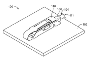
図1は、1つの例示的な実施形態に従い形成された同軸ケーブルアセンブリ100の上面斜視図である。図2は、同軸ケーブルアセンブリ100の部分的な分解図である。同軸ケーブルアセンブリ100は回路基板102に載置されるように構成されている。1つの例示的な実施形態において同軸ケーブルアセンブリ100は、その間の中間コネクターを必要とすることなく、直接回路基板102に接続される。
FIG. 1 is a top perspective view of a
同軸ケーブルアセンブリ100は、同軸ケーブル104、ケーブルハウジング106、ケーブルシールド108およびベースシェル110を含む。同軸ケーブル104、ケーブルハウジング106およびケーブルシールド108は、ベースシェル110に挿入されるように構成されているケーブルサブアセンブリ111を規定し、同軸ケーブル104を回路基板102に電気的に終端処理する。ベースシェル110は、回路基板102に直接載置される。同軸ケーブル104はケーブルハウジング106の中で受容され、ケーブルシールド108はケーブルハウジング106につながり、同軸ケーブル104に電気的な遮蔽を提供する。同軸ケーブル104、ケーブルハウジング106およびケーブルシールド108は、ベースシェル110内に装着され、同軸ケーブル104は回路基板102に直接つながる。
The
図2に示すように、同軸ケーブル104は導体112、導体112を取り囲む絶縁体114、絶縁体114を取り囲む外側導体116および外側導体116を取り囲む外部被覆118を含む。1つの例示的な実施形態において、導体112は同軸ケーブル104の中心ワイヤーにより規定され、以降、中心ワイヤー112として呼んでよい。絶縁体114は中心ワイヤー112を外側導体116から絶縁する。必要に応じて、外側導体116は編組線、箔または中心ワイヤー112に対する他の種類の遮蔽であってもよい。同軸ケーブル104は、同軸ケーブル104の終端120を剥離することにより準備され、中心ワイヤー112を露出する。必要に応じて、さらに外側導体116も終端120において露出してもよい。
As shown in FIG. 2, the
導体112の露出部分は、回路基板102に直接電気的につながるように構成されている。外側導体116の露出部分は、ケーブルシールド108および/またはベースシェル110に電気的に接続するように構成されている。1つの例示的な実施形態において、ベースシェル110はケーブルシールド108および/またはケーブルハウジング106を押し付け、中心ワイヤー112を回路基板102に押し付け、それらに電気的に接続する。分離可能で、押し込み可能な電気的接続は中心ワイヤー112と回路基板102との間で、例えば回路基板102上の信号用パッドに対して行われる。
The exposed portion of the
ケーブルハウジング106は、同軸ケーブル104を受容するケーブルチャネル122を含む。必要に応じて、同軸ケーブル104は締まり嵌めによってケーブルチャネル122内に保持される。あるいは、保持機能は、ケーブルチャネル122内で同軸ケーブル104を固定するように提供されてもよい。ケーブルチャネル122は同軸ケーブル104を受容するように成形されてもよい。必要に応じて、ケーブルチャネル122は複数の異なる直径の同軸ケーブル104を受容し、複数の異なるサイズの同軸ケーブル104を収容してもよい。
The
ケーブルハウジング106は、ケーブルハウジング106の前端においてノーズ124を含む。導体スロット126はノーズ124において提供される。必要に応じて、導体スロット126はノーズ124の前部で開口してもよい。あるいは、導体スロット126は、ノーズ124を通る内部の通路(an internal passage)であってもよい。導体スロット126は中心ワイヤー112を受容し、絶縁体114の一部を受容してもよい。必要に応じて、導体スロット126は外側導体116の一部を受容してもよい。組立の際、同軸ケーブル104の終端120はノーズ124に巻き付けられ、中心ワイヤー112は導体スロット126内に受容される。中心ワイヤー112はケーブルハウジング106の底部128に巻きつく。底部128は一般的にケーブルチャネル122の反対側にある。ケーブルハウジング106はベースシェル110内に受容され、底部128は回路基板102と平行に延在する。中心ワイヤー112の露出部分は、回路基板102に直接終端処理されるように、底部128に沿って露出する。
The
図3は、ケーブルサブアセンブリ111の部分的な分解図である。同軸ケーブル104は、ケーブルハウジング106につながれて示されている。同軸ケーブル104はケーブルチャネル122内で受容される。同軸ケーブル104の終端120はノーズ124に巻き付けられ、終端120は導体スロット126で受容される。必要に応じてノーズ124は、同軸ケーブル104が滑らかに移動できるように丸みを帯びてもよい。1つの例示的な実施形態において、外側導体116の一部はノーズ124に沿って露出する。
FIG. 3 is a partially exploded view of the
ケーブルハウジング106は、向かい合った側面130、132を含む。側面130、132は、そこから外側に広がる留め具(catch)134を有する。留め具134は、ケーブルシールド108をケーブルハウジング106に固定するように用いられる。側面130、132はケーブルハウジング106の上部136にまで延在する。1つの例示的な実施形態において、ケーブルチャネル122は上部136を通って開口し、同軸ケーブル104は、開口した上部136を通ってケーブルチャネル122の上に装着されてもよい。あるいは、上部136は閉じられてもよく、同軸ケーブル104はケーブルハウジング106の後部138を通って装着されてもよい。
ケーブルシールド108は、ケーブルハウジング106につながるように構成されている。1つの例示的な実施形態において、ケーブルシールド108は金属材料(例えば、銅材料または別の導体材料)から製造され、ケーブルサブアセンブリ111に電気的な遮蔽を提供する。1つの例示的な実施形態において、ケーブルシールド108は、型打ち成形された部品であってもよい。ケーブルシールド108は、側面140、142、および側面140と142との間に広がる上部144を含む。窓146は、側面140、142を通って開口している。ケーブルシールド108がケーブルハウジング106につながる際、窓146は留め具134を受容する。
The
ケーブルシールド108は、ケーブルシールド108の後部150において張力緩和部(strain relief)148を含む。張力緩和部148は同軸ケーブル140につながるように構成され、ケーブルサブアセンブリ111と同軸ケーブル104との間に張力緩和部を提供する。必要に応じて、張力緩和部148は同軸ケーブル104に圧着(crimp)してもよい。別の実施形態においては、他の固定方法を用いてケーブルシールド108を同軸ケーブル104に固定してもよい。
The
ケーブルシールド108は、ケーブルシールド108の前部154にスプリングフィンガー(spring finger)152を含む。スプリングフィンガー152はノーズ124に沿って延在する。スプリングフィンガー152は、ケーブルシールド108がケーブルハウジング106につながった際、外側導体116の露出部分と係合するように構成されている。スプリングフィンガー152は外側導体116に対してばね付勢されてもよく、ケーブルシールド108と外側導体116との間で確実に電気的な接続が維持される。スプリングフィンガー152は、ノーズ124に直接係合してもよい。1つの例示的な実施形態において、スプリングフィンガー152は、外側導体116の前方にある絶縁体114に係合するように構成されている。スプリングフィンガー152は絶縁体114を押しつけて、絶縁体114および導体112(図1で示す)を導体スロット126内に緊密に保持する。
The
図4は、1つの例示的な実施形態に従い形成されたケーブルサブアセンブリ111の正面図である。図5は、ケーブルサブアセンブリ111の底面図である。図6は、ケーブルサブアセンブリの側面図である。導体112は、ケーブルハウジング106のノーズ124の周りからケーブルハウジング106の底部128へと巻き付いて示される。導体112の露出部分は、回路基板102(図1に示す)に直接電気的に接続するように底部128で露出する。
FIG. 4 is a front view of a
導体112の露出部分は、導体112の露出部分の先端において連結界面(mating interface)160を含む。連結界面160は、回路基板102を押しつけられるように構成されている。連結界面160は、回路基板102から分離可能である。連結界面160は、回路基板102との間でのはんだ付け接続無しに、回路基板102と直接電気的に接続する。連結界面160は、例えば接点または端子のような、その間に別の部材または界面なしに、回路基板102と電気的に接続する。1つの界面は中心ワイヤー112と回路基板102の信号用パッドとの間に規定される。
The exposed portion of the
図5に示すように、導体112の端162はケーブルハウジング106に固定されている。必要に応じて、ケーブルハウジング106は、導体112の端162を受容する堅穴(well)164を含んでもよい。端162は、例えば、ケーブルハウジング106のプラスチック材料の変形、つば出し成形(dimpling)もしくはコイニングのような固定手段または機構(または特徴、features)により、エポキシ樹脂を用いる事により、または別の部品を用いることにより、堅穴164内に固定されてもよい。
As shown in FIG. 5, the
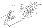
図7は、ベースシェル110内に装着されているケーブルサブアセンブリ111を示す同軸ケーブルアセンブリ100を例示する。図8は、ベースシェル110内に装着されているケーブルサブアセンブリ111を示す同軸ケーブルアセンブリ100の側面図である。ベースシェル110は、回路基板102の表面172につながれたベース170を含む。必要に応じて、ベース170は表面172にはんだ付けされてもよい。別の実施形態において、ベース170は、他の手段または機構を用いて表面172に固定されてもよく、例えば、ファスナー(または締結具、fasteners)、干渉タブおよび同様のものを用いてもよい。ベースシェル110は、ベース170から延在する側壁174、176を含む。
FIG. 7 illustrates the
ベースシェル110は、ベースシェル110の前部180に近接するばねレバー178を含む。空洞182は、側壁174、176およびばねレバー178との間に規定される。空洞182は、ケーブルサブアセンブリ111を受容する。1つの例示的な実施形態において、ベースシェル110は、側壁174、176から空洞182内に延在する保持タブ184を含む。保持タブ184は、ベースシェル110の後部に近接して位置する。保持タブ184はケーブルサブアセンブリ111に係合するように構成され、ケーブルサブアセンブリ111は空洞182内に保持される。例えば、保持タブ184がケーブルハウジング106の後部138に係合するように構成され、ケーブルサブアセンブリ111の空洞182からの引き抜きを制限する。ひとたびケーブルサブアセンブリ111が空洞182内に装着されると、保持タブ184はケーブルサブアセンブリ111の反発動作(reward movement)に抵抗する。
ベースシェル110は、側壁174、176から延在するラッチ(または掛け金、latches)188を含む。ラッチ188は、ケーブルサブアセンブリ111より上部の、ベースシェル110の蓋190を固定するように用いられる。蓋190は、ベースシェル110の前部180から延在する。例示された実施形態において、蓋190は自在に回転できるようにベース170につながる。ケーブルサブアセンブリ111が空洞182内に装着された後、蓋190は閉じられケーブルサブアセンブリ111を空洞182内に保持する。カバー190は、ラッチ188と相互に作用して蓋190を側壁174、176に固定するラッチタブ(latching tab)192を含む。必要に応じて、蓋190はケーブルサブアセンブリ111に押しつけて、ケーブルサブアセンブリ111を回路基板102に対して押しつけてもよい。
1つの例示的な実施形態において、蓋190は、ケーブルシールド108にばね付勢するように構成されている接地フィンガー(grounding finger)194を含む。接地フィンガー194は、ベースシェル110をケーブルシールド108に電気的に接続する。接地フィンガー194は、ケーブルサブアセンブリ111の上部に対してばね力を与え、ケーブルサブアセンブリを回路基板102に対して下向きに押しつけることができる。
In one exemplary embodiment, the
組立の際、ケーブルサブアセンブリ111はベースシェル110内に挿入される。必要に応じて、ケーブルサブアセンブリ111は空洞182内に斜めに装着し、それから最終位置へ回転してもよい。ノーズ124は、ばねレバー178の下の空洞182内に装着される。ばねレバー178はノーズ124の上部に係合し、ケーブルサブアセンブリ111を回路基板102に下向きに押しつける。1つの例示的な実施形態において、ばねレバー178はケーブルシールド108上のスプリングフィンガー152に係合し、ベースシェル110をケーブルシールド108に電気的に接続する。1つの例示的な実施形態において、ばねレバー178は、ワイヤー112(図2に示す)の露出部分の直上のケーブルサブアセンブリ111に、下向きに垂直な力を与え、中心ワイヤー112を回路基板102(例えば、回路基板102の信号用パッド)に押しつける。中心ワイヤー112と回路基板102との間で、押し込み可能な接続がなされる。押し込みは、少なくとも一部分において、ばねレバー178により与えられる。
During assembly, the
図9は、同軸ケーブルアセンブリ100の側面図である。図10は、同軸ケーブルアセンブリ100の断面図である。ひとたび組み立てられると、ケーブルサブアセンブリ111は、ベースシェル110によって空洞182内に保持される。蓋190はケーブルサブアセンブリ111の上部を押しつけ、ケーブルサブアセンブリ111を空洞182内に保持する。保持タブ184はケーブルハウジング106の後方に延在し、ケーブルサブアセンブリ111を空洞182内に保持する。
FIG. 9 is a side view of the
同軸ケーブルアセンブリ100は、回路基板102に電気的に接続する。導体112の露出部分は回路基板102に直接係合する。同軸ケーブル104はノーズ124に巻き付く。導体112の端162は堅穴164に受容され、その中で固定される。連結界面160は、導体112の先端または最下点において規定される。
The
1つの例示的な実施形態において、ケーブルハウジング106は頭頂部196を含む。導体112は頭頂部196の周りに曲げられ、回路基板102と直接電気的に接続するように配置される。1つの例示的な実施形態において、ケーブルハウジング106は、後部138に近接する足198を含む。足198は、回路基板102と平行に、ケーブルハウジング106の底部128に配置する。1つの例示的な実施形態において、足198は、回路基板102に載置されるため連結界面160と同一平面上にある。
In one exemplary embodiment,
図11は、1つの例示的な実施形態に従い形成したケーブルサブアセンブリ211の分解図である。ケーブルサブアセンブリ211は、同軸ケーブルアセンブリ200(図12に示す)の一部として用いられる。ケーブルサブアセンブリ211は、ケーブルサブアセンブリ111(図1に示す)と同様であるが、ケーブルサブアセンブリ211は、回路基板の信号用パッドへ直接電気的終端処理をするために、ケーブルハウジングの内部に保持される中心ワイヤーのかぎ形状の端を含み、ケーブルサブアセンブリ111のようにケーブルハウジングの前部に巻き付けられることとは対照的である。
FIG. 11 is an exploded view of a
図12は、同軸ケーブルアセンブリ200の断面図である。同軸ケーブルアセンブリ200は回路基板202に直接つながり、その間を媒介するコネクターを必要としない。同軸ケーブルアセンブリ200は、同軸ケーブル204、ケーブルハウジング206、ケーブルシールド208およびベースシェル210を含む。同軸ケーブル204、ケーブルハウジング206およびケーブルシールド208は、ベースシェル210に挿入されるように構成されているケーブルサブアセンブリ211を規定し、同軸ケーブル204を回路基板202に電気的に終端処理する。ベースシェル210は回路基板202に直接載置される。同軸ケーブル204はケーブルハウジング206内で受容され、ケーブルシールド208はケーブルハウジング206につながれて、同軸ケーブル204に電気的な遮蔽を提供する。
FIG. 12 is a cross-sectional view of the
図11に戻り、同軸ケーブル204は導体212、導体212を取り囲む絶縁体214、絶縁体214を取り囲む外側導体216および外側導体216を取り囲む外部被覆218を含む。1つの例示的な実施形態において、導体212は同軸ケーブル204の中心ワイヤーによって規定され、以降、中心ワイヤー212として呼んでよい。中心ワイヤー212は、回路基板202(図12に示す)に直接電気的に接続するように、同軸ケーブル204の終端220で露出する。中心ワイヤー212の露出部分は、ケーブルハウジング206への装着のため、および分離可能な連結界面における回路基板202への直接つながるために、所定の形状に曲げられる。1つの例示的な実施形態において、中心ワイヤー212はかぎ形状に曲げられる。中心ワイヤー212の露出部分はU字形状に曲げられてもよく、端部は同軸ケーブル204のケーブルの軸方向に大まかに垂直に延在する。
Returning to FIG. 11, the
ケーブルハウジング206は、同軸ケーブル204を受容するケーブルチャネル222を含む。ケーブルハウジング206は、ケーブルハウジング206の前端でノーズ224を含む。導体スロット226はノーズ224において提供される。必要に応じて、導体スロット226は内側に開口してもよく、ノーズ224の前部は導体スロット226の前方で閉じてもよい。導体スロット226は、ノーズ224を通る内部通路である。導体スロット226は中心ワイヤー212を受容し、絶縁体214の一部を受容してもよい。必要に応じて、導体スロット226は外側導体216の一部を受容してもよい。図12に示すように、組立の際、中心ワイヤー212の露出部分はノーズ224の内部の導体スロット226の表面によって規定される頭頂部296の周りに引っかけられる。頭頂部296は、ケーブルハウジング206の底部228の近くに位置し、頭頂部296は中心ワイヤー212のU字形状の一部を受容する。必要に応じて、中心ワイヤー212は、事前に曲げられるよりもむしろ、組立中に頭頂部296に巻き付けられてもよい。ケーブルハウジング206は、頭頂部296の前方に堅穴264を含み、中心ワイヤー212の端262を受容する。端262は堅穴264内に固定されてもよい。
ケーブルハウジング206は、向かい合った側面230、232を含む。側面230、232は、そこから外側に広がる留め具234を有する。留め具234は、ケーブルシールド208をケーブルハウジング206に固定するように用いられる。側面230、232は、ケーブルハウジング206の上部236にまで延在する。1つの例示的な実施形態において、ケーブルチャネル222は上部236を通って開口しており、同軸ケーブル204は開口した上部236を通ってケーブルチャネル222の上に装着されてもよい。あるいは、上部236は閉じていてもよく、同軸ケーブル204はケーブルハウジング206の後部238を通って装着されてもよい。
ケーブルシールド208は、ケーブルハウジング206につながるように構成されている。1つの例示的な実施形態において、ケーブルシールド208は金属材料(例えば、銅材料または別の導体材料)から製造され、同軸ケーブルアセンブリ200に電気的な遮蔽を提供する。1つの例示的な実施形態において、ケーブルシールド208は、型打ち成形された部品であってもよい。ケーブルシールド208は、側面240、242、および側面240と242との間に広がる上部244を含む。側面240、242は側面230、232と平行に延在し、ケーブルハウジング206上のケーブルシールド208を留める(clip)。留め具234は側面240、242の後方に位置し、ケーブルハウジング206が後方にすべり外れないようにケーブルシールド208を保持する。
The
ケーブルシールド208は、ケーブルシールド208の後部250に張力緩和部248を含む。ケーブルシールド208は、ケーブルシールド208がケーブルハウジング206につながる際、外側導体216の露出部分と係合するように構成されているスプリングフィンガー252を含む。
The
図12を参照して、ベースシェル210は、ベースシェル210の前部280に近接するばねレバー278を含む。空洞282は、ベースシェル210によって規定される。空洞282はケーブルサブアセンブリ211を受容する。ばねレバー278は、ノーズ224の上部と係合し、ケーブルサブアセンブリ211を回路基板202に下向きに押しつける。1つの例示的な実施形態において、ばねレバー278はケーブルシールド208と係合し、ベースシェル210をケーブルシールド208に電気的に接続する。1つの例示的な実施形態において、ばねレバー278は、中心ワイヤー212の露出部分の直上部のケーブルサブアセンブリ211に下向きに垂直な力を与え、中心ワイヤー212を回路基板202(例えば、回路基板202の信号用パッド)に押し付ける。中心ワイヤー212と回路基板202との間で、押し込み可能な接続がなされる。押し込みは、少なくとも一部分において、ばねレバー278により与えられる。
With reference to FIG. 12, the
ケーブルサブアセンブリ211が空洞282に装着された後、蓋290は閉じられ、ケーブルサブアセンブリ211を空洞282内に保持する。蓋290は、ケーブルシールド208にばね付勢するように構成されている接地フィンガー294を含む。接地フィンガー294は、ベースシェル210をケーブルシールド208に電気的に接続する。接地フィンガー294は、ケーブルサブアセンブリ211の上部に対してばね力を与え、ケーブルサブアセンブリを回路基板202に対して下向きに押しつけることができる。
After the
図13は、1つの例示的な実施形態に従って形成したケーブルサブアセンブリ211の正面図である。図14は、ケーブルサブアセンブリ211の正面斜視図である。図15は、ケーブルサブアセンブリ211の側面図である。図16は、ケーブルサブアセンブリ211の底面図である。導体212は、回路基板202(図12に示す)に直接電気的に接続するように、ケーブルハウジング206の底部228に沿って露出して示される。
FIG. 13 is a front view of a
導体212の露出部分は、導体212の露出部分の先端において連結界面260を含む。連結界面260は、回路基板202に押しつけられるように構成されている。連結界面260は、回路基板202から分離可能である。連結界面260は、回路基板202との間でのはんだ付け接続無しに、回路基板202と直接電気的に接続する。連結界面260は、例えば接点または端子のような、その間に別の部材また界面なしに、回路基板202と電気的に接続する。1つの界面は中心ワイヤー212と回路基板202の信号用パッドとの間に規定される。
The exposed portion of the
図17は、1つの例示的な実施形態に従って形成したケーブルサブアセンブリ311の分解図である。ケーブルサブアセンブリ311は、同軸ケーブルアセンブリ300(図18に示す)の一部として用いられる。ケーブルサブアセンブリ311は、ケーブルサブアセンブリ111(図1に示す)と同様であるが、ケーブルサブアセンブリ311は、中心ワイヤー312とくさび状の接触部313の両方により規定され、回路基板の信号用パッドに直接電気終端処理をするためにケーブルハウジングによって保持される導体301を含み、中心ワイヤーのみによって規定される導体112(図2に示す)とは対照的である。
FIG. 17 is an exploded view of a
図18は、同軸ケーブルアセンブリ300の断面図である。同軸ケーブルアセンブリ300は、その間に中間コネクターを必要とすることなく回路基板302に直接つながる。同軸ケーブルアセンブリ300は同軸ケーブル304、ケーブルハウジング306、ケーブルシールド308およびベースシェル310を含む。同軸ケーブル304、ケーブルハウジング306およびケーブルシールド308は、ベースシェル310に挿入されるように構成されているケーブルサブアセンブリ311を規定し、回路基板302に導体301を電気的な終端処理をする。ベースシェル310は回路基板302に直接載置される。同軸ケーブル304およびくさび状の接触部313はケーブルハウジング306内で受容され、ケーブルシールド308はケーブルハウジング306につながり、同軸ケーブル304およびくさび状の接触部313に電気的な遮蔽を提供する。
FIG. 18 is a cross-sectional view of the
図17に戻り、同軸ケーブル304は中心ワイヤー312、中心ワイヤー312を取り囲む絶縁体314、絶縁体314を取り囲む外側導体316、および外側導体316を取り囲む外部被覆318を含む。中心ワイヤー312は、くさび状の接触部313に直接電気的に接続するように、同軸ケーブル304の終端320において露出する。必要に応じて、くさび状の接触部313は中心ワイヤー312に圧着されてもよい。あるいは、くさび状の接触部313は中心ワイヤー312に、はんだ付けまたは他の電気的および/または機械的につながれてもよい。くさび状の接触部313はその端部に、回路基板302(図18に示す)に直接電気的に接続するように構成されている連結界面360を有する。くさび状の接触部313は、中心ワイヤー312の端部364を受容するワイヤーバレル(wire barrel)362を有する。くさび状の接触部313は、ワイヤーバレル362から延在する連結タブ(mating tab)366を有する。連結タブ366の端部は、連結界面360を規定する。必要に応じて、くさび状の接触部313は型打ち成形されてもよい。くさび状接触部313を締まり嵌めによってケーブルハウジング306内に固定するように、くさび状接触部313はくさび形状を有してもよい。くさび状接触部313は、連結界面360においてくさび形状を有して、ケーブルサブアセンブリ311をベースシェル310内に装着している間、連結界面360を回路基板302に押し込んでもよい。
Returning to FIG. 17, the
ケーブルハウジング306は、同軸ケーブル304を受容するケーブルチャネル322を含む。ケーブルハウジング306は、ケーブルハウジング306の前端部においてノーズ324を含む。導体スロット326は、ノーズ324において提供される。必要に応じて、前部を通るくさび状接触部313を受容するために、導体スロット326はノーズ324の前部において開口していてもよい。導体スロット326は、前部とケーブルチャネル322との間で開口していてもよく、くさび状接触部313を中心ワイヤー312に終端処理するために中心ワイヤー312がケーブルチャネル322から導体スロット326へ通り抜けることができる。導体スロット326は中心ワイヤー312を受容し、絶縁体314の一部を受容してもよい。必要に応じて、導体スロット326は外側導体316の一部を受容してもよい。
The
ケーブルハウジング306は向かい合った側面330、332を含む。側面330、332は、そこから外側に広がる留め具334を有する。留め具334は、ケーブルシールド308をケーブルハウジング306に固定するように用いられる。側面330、332はケーブルハウジング306の上部336にまで延在する。1つの例示的な実施形態において、ケーブルチャネル322は上部336を通って開口し、同軸ケーブル304は開口した上部336を通ってケーブルチャネル322の上に装着されてもよい。あるいは、上部336は閉じられてもよく、同軸ケーブル304はケーブルハウジング306の後部338を通って装着されてもよい。
ケーブルシールド308は、ケーブルハウジング306につながるように構成されている。1つの例示的な実施形態において、ケーブルシールド308は金属材料(例えば、銅材料または別の導体材料)から製造され、同軸ケーブルセンブリ300に電気的な遮蔽を提供する。1つの例示的な実施形態において、ケーブルシールド308は、型打ち成形された部品であってもよい。ケーブルシールド308は、側面340、342、および側面340と342との間に広がる上部344を含む。側面340、342は側面330、332と平行に延在し、ケーブルハウジング306上のケーブルシールド308を留める。留め具334は側面340、342の後方に位置し、ケーブルハウジング306が後方にすべり外れないようにケーブルシールド308を保持する。
The
ケーブルシールド308は、ケーブルシールド308の後部350に張力緩和部348を含む。ケーブルシールド308は、ケーブルシールド308がケーブルハウジング306につながる際、外側導体316の露出部分と係合するように構成されているスプリングフィンガー352を含む。
The
図18を参照して、ベースシェル310は、ベースシェル310の前部380に近接するばねレバー378を含む。空洞382は、ベースシェル310によって規定される。空洞382はケーブルサブアセンブリ311を受容する。ばねレバー378は、ノーズ324の上部と係合し、ケーブルサブアセンブリ311を回路基板302に下向きに押しつける。1つの例示的な実施形態において、ばねレバー378はケーブルシールド308と係合し、ベースシェル310をケーブルシールド308と電気的に接続する。1つの例示的な実施形態において、ばねレバー378は、くさび状接触部313の露出部分の直上部のケーブルサブアセンブリ311に下向きに垂直な力を与え、くさび状接触部313を回路基板302(例えば、回路基板302の信号用パッド)に押し付ける。くさび状接触部313と回路基板302との間で、押し込み可能な接続がなされる。押し込みは、少なくとも一部分において、ばねレバー378により与えられる。
With reference to FIG. 18, the
ケーブルサブアセンブリ311が空洞382に装着された後、蓋390は閉じられ、ケーブルサブアセンブリ311を空洞382内に保持する。蓋390は、ケーブルシールド308にばね付勢するように構成されている接地フィンガー394を含む。接地フィンガー394は、ベースシェル310をケーブルシールド308に電気的に接続する。接地フィンガー394は、ケーブルサブアセンブリ311の上部に対してばね力を与え、ケーブルサブアセンブリを回路基板302に対して下向きに押しつけることができる。
After the
図19は、1つの例示的な実施形態に従って形成したケーブルサブアセンブリ311の正面図である。図20は、ケーブルサブアセンブリ311の側面図である。導体301は、回路基板302(図20に示す)に直接電気接続するために、ケーブルハウジング306の底部328に沿って露出して示される。
FIG. 19 is a front view of a
くさび状接触部313は、回路基板302に押し込まれるように構成されている導体301の露出部分を規定する。連結界面360は、回路基板302から分離可能である。連結界面360は、回路基板302との間でのはんだ付け接続無しに、回路基板302と直接電気につながる。連結界面360は、例えば連結接点または連結端子のような、その間に別の部材または界面なしに、回路基板302と電気的に接続する。2つの界面のみが中心ワイヤー312と回路基板302の信号用パッドとの間に規定されるが、すなわち、中心ワイヤー312とくさび状接触部313との間の界面と、くさび状接触部313と回路基板302の信号用パッドとの間の界面である。
The wedge-shaped
当然のことながら、上述したことは例示であって、限定するものではないことを意図する。例えば、上述の実施形態(および/またはその態様)は、互いに組み合わせて用いてもよい。さらに、特定の状況または材料に適応するように、本範囲から逸脱することなく多くの改良が本発明の内容に対してなされてもよい。寸法、材料の種類、様々な成分の配向性、ならびに本明細書に記載される様々な成分の数および配置は、ある実施形態のパラメータを規定するように意図され、また決して限定的ではなく、単なる例示的な実施形態である。他の多くの実施形態、ならびに本発明の精神および請求の範囲内での改良は、当業者が上述のことを考察するにあたり明白である。従って、本発明の範囲は添付の請求項を参照して、加えてこのような権利を付与される請求項と均等な全ての請求の範囲とともに決定されるべきである。添付する請求項における、“〜を含む(including)”および“in which”は、平易な英語で言うところ、それぞれ“〜を含む(comprising)”および“wherein”と同等の意味で用いられる。さらに、次の請求項で、“第1の”、“第2の”および“第3の”等の用語は、単なる分類として用いられ、その対象に数的な条件を与えることを意図していない。
なお、本発明の実施形態は以下の態様を含む。
・態様1:
同軸ケーブルアセンブリであって、導体が露出している終端を有する同軸ケーブルと、前記同軸ケーブルを保持し、前記露出した導体を受容する導体スロットを有するケーブルハウジングと、前記ケーブルハウジングにつながり、前記同軸ケーブルの前記終端に電気的な遮蔽を提供するケーブルシールドと、を含み、前記ケーブルハウジングが回路基板につながるように構成され、前記露出した導体が前記回路基板の信号用パッドに電気的に接続するように直接係合する、同軸ケーブルアセンブリ。
・態様2:
前記導体が、分離可能な界面において前記回路基板の前記信号用パッドに直接つながるように構成されている、態様1に記載の同軸ケーブルアセンブリ。
・態様3:
前記導体が、前記同軸ケーブルの中心ワイヤーを含み、前記信号用パッドに直接係合するように前記中心ワイヤーが前記導体スロット内で保持されている、態様1に記載の同軸ケーブルアセンブリ。
・態様4:
前記導体が、前記同軸ケーブルの中心ワイヤーと前記中心ワイヤーに終端処理されるくさび状の接触部とを含み、前記信号用パッドに直接係合するように前記くさび状の接触部が前記導体スロット内に保持されている、態様1に記載の同軸ケーブルアセンブリ。
・態様5:
前記ケーブルハウジングが前記ケーブルハウジングの端部においてノーズを含み、前記導体スロットが前記ノーズにおいて提供され、前記信号用パッドに直接載置されるように前記導体が前記ノーズにおいて露出している、態様1に記載の同軸ケーブルアセンブリ。
・態様6:
前記ケーブルハウジングが、前記回路基板に対してばね付勢されるように構成され、前記ケーブルハウジングが前記回路基板につながれる際に前記露出した導体が前記信号用パッドに対して押しつけられている、態様1に記載の同軸ケーブルアセンブリ。
・態様7:
前記ケーブルシールドが前記同軸ケーブルの外側導体に電気的に接続されている、態様1に記載の同軸ケーブルアセンブリ。
・態様8:
前記ケーブルハウジングが前記ケーブルシールド内に頭頂部を含み、前記導体が前記同軸ケーブルの中心ワイヤーを含み、前記中心ワイヤーが前記頭頂部の周りで曲げられ、前記信号用パッドに対して押しつけられるように構成された先端を規定する、態様1に記載の同軸ケーブルアセンブリ。
・態様9:
前記回路基板に載置されるように構成されているベースシェルをさらに含み、前記ベースシェルが、前記露出した導体を前記信号用パッドに押しつけるように前記ケーブルハウジングおよび前記ケーブルシールドの少なくとも1つに対してばね付勢されるばねレバーを含む、態様1に記載の同軸ケーブルアセンブリ。
・態様10:
前記ケーブルハウジングが前記回路基板に対向するように構成されている底部を含む、態様1に記載の同軸ケーブルアセンブリ。
・態様11:
前記ベースシェルが前記回路基板の前記信号用パッド上の前記回路基板につながるように構成され、前記ベースシェルが空洞を有し、前記ケーブルハウジングおよびケーブルシールドが前記ベースシェルの前記空洞内に装着され、前記ベースシェルが前記ケーブルハウジングを保持している、態様1に記載の同軸ケーブルアセンブリ。
Of course, what has been described above is intended to be illustrative and not limiting. For example, the above-described embodiments (and / or aspects thereof) may be used in combination with each other. In addition, many modifications may be made to the content of the invention without departing from the scope so as to accommodate particular circumstances or materials. The dimensions, material types, orientation of the various components, and the number and arrangement of the various components described herein are intended to define the parameters of certain embodiments, and are in no way limiting. It is merely an exemplary embodiment. Many other embodiments, and modifications within the spirit and scope of the invention, will be apparent to those skilled in the art from a consideration of the foregoing. The scope of the invention should, therefore, be determined with reference to the appended claims, along with all claims that are equivalent to the claims entitled to such rights. In the appended claims, “including” and “in which” are used in plain English to mean equivalent to “comprising” and “wherein”, respectively. Further, in the following claims, terms such as “first”, “second” and “third” are used as mere classifications and are intended to give a numerical condition to the subject. Absent.
The embodiment of the present invention includes the following aspects.
Aspect 1:
A coaxial cable assembly having a terminal with an exposed conductor, a cable housing having a conductor slot holding the coaxial cable and receiving the exposed conductor, and connected to the cable housing, the coaxial A cable shield that provides electrical shielding to the end of the cable, wherein the cable housing is configured to connect to a circuit board, and the exposed conductor electrically connects to a signal pad on the circuit board Coaxial cable assembly that engages directly.
-Aspect 2:
The coaxial cable assembly according to aspect 1, wherein the conductor is configured to directly connect to the signal pad of the circuit board at a separable interface.
Aspect 3:
The coaxial cable assembly according to aspect 1, wherein the conductor includes a center wire of the coaxial cable, and the center wire is held in the conductor slot so as to directly engage the signal pad.
Aspect 4:
The conductor includes a center wire of the coaxial cable and a wedge-shaped contact portion terminated to the center wire, and the wedge-shaped contact portion is disposed in the conductor slot so as to directly engage with the signal pad. The coaxial cable assembly according to aspect 1, wherein
-Aspect 5:
Aspect 1 wherein the cable housing includes a nose at an end of the cable housing, the conductor slot is provided in the nose, and the conductor is exposed at the nose such that it is placed directly on the signal pad. A coaxial cable assembly according to claim 1.
-Mode 6:
The cable housing is configured to be spring-biased with respect to the circuit board, and the exposed conductor is pressed against the signal pad when the cable housing is connected to the circuit board. The coaxial cable assembly according to aspect 1.
-Mode 7:
The coaxial cable assembly according to aspect 1, wherein the cable shield is electrically connected to an outer conductor of the coaxial cable.
Aspect 8:
The cable housing includes a top in the cable shield, the conductor includes a center wire of the coaxial cable, and the center wire is bent around the top and pressed against the signal pad. The coaxial cable assembly according to aspect 1, wherein the coaxial cable assembly defines a configured tip.
Aspect 9:
And a base shell configured to be mounted on the circuit board, wherein the base shell is against at least one of the cable housing and the cable shield to press the exposed conductor against the signal pad. A coaxial cable assembly according to aspect 1, comprising a spring lever that is spring biased against.
Aspect 10:
The coaxial cable assembly of aspect 1, wherein the cable housing includes a bottom configured to face the circuit board.
Aspect 11:
The base shell is configured to connect to the circuit board on the signal pad of the circuit board, the base shell has a cavity, and the cable housing and the cable shield are mounted in the cavity of the base shell. The coaxial cable assembly according to aspect 1, wherein the base shell holds the cable housing.
Claims (10)
導体が露出している終端を有する同軸ケーブルと、
前記同軸ケーブルを保持し、前記露出した導体を受容する導体スロットを有するケーブルハウジングと、
前記ケーブルハウジングにつながり、前記同軸ケーブルの前記終端に電気的な遮蔽を提供するケーブルシールドと、
を含み、前記ケーブルハウジングが回路基板につながるように構成され、前記露出した導体が前記回路基板の信号用パッドに電気的に接続するように直接係合し、
前記回路基板に載置されるように構成されているベースシェルをさらに含み、前記ベースシェルが、前記露出した導体を前記信号用パッドに押しつけるように前記ケーブルハウジングおよび前記ケーブルシールドの少なくとも1つに対してばね付勢されるばねレバーを含む、同軸ケーブルアセンブリ。 A coaxial cable assembly,
A coaxial cable having a termination with exposed conductors;
A cable housing having a conductor slot for holding the coaxial cable and receiving the exposed conductor;
A cable shield connected to the cable housing and providing electrical shielding for the end of the coaxial cable;
Hints, said cable housing is configured to be connected to the circuit board, and directly engage so that the exposed conductors are electrically connected to the signal pads of the circuit board,
And a base shell configured to be mounted on the circuit board, wherein the base shell is against at least one of the cable housing and the cable shield to press the exposed conductor against the signal pad. A coaxial cable assembly including a spring lever that is spring biased against .
Applications Claiming Priority (2)
| Application Number | Priority Date | Filing Date | Title |
|---|---|---|---|
| US13/561,444 | 2012-07-30 | ||
| US13/561,444 US8939794B2 (en) | 2012-07-30 | 2012-07-30 | Coaxial cable assembly |
Publications (3)
| Publication Number | Publication Date |
|---|---|
| JP2014067695A JP2014067695A (en) | 2014-04-17 |
| JP2014067695A5 JP2014067695A5 (en) | 2014-09-11 |
| JP5798158B2 true JP5798158B2 (en) | 2015-10-21 |
Family
ID=49995311
Family Applications (1)
| Application Number | Title | Priority Date | Filing Date |
|---|---|---|---|
| JP2013156829A Expired - Fee Related JP5798158B2 (en) | 2012-07-30 | 2013-07-29 | Coaxial cable assembly |
Country Status (4)
| Country | Link |
|---|---|
| US (1) | US8939794B2 (en) |
| JP (1) | JP5798158B2 (en) |
| KR (1) | KR20140016189A (en) |
| CN (1) | CN103579794B (en) |
Families Citing this family (22)
| Publication number | Priority date | Publication date | Assignee | Title |
|---|---|---|---|---|
| TWI479960B (en) * | 2012-12-28 | 2015-04-01 | Hon Hai Prec Ind Co Ltd | Fixing device for fixing flexible cable and electric device using same |
| JP6005575B2 (en) * | 2013-04-11 | 2016-10-12 | 日本航空電子工業株式会社 | connector |
| US9306325B2 (en) * | 2014-03-18 | 2016-04-05 | Cho-Yao Cheng | Plug, socket and their combined structure of electrical connector |
| US9405331B2 (en) * | 2014-08-07 | 2016-08-02 | Dell Products L.P. | Cable grounding system for an information handling system |
| US9960510B2 (en) * | 2016-05-18 | 2018-05-01 | J.S.T. Mfg. Co., Ltd. | Connector |
| CN205960252U (en) * | 2016-07-12 | 2017-02-15 | 泰科电子(上海)有限公司 | Connecting device and connecting device assembly |
| JP6761730B2 (en) | 2016-10-28 | 2020-09-30 | 日本航空電子工業株式会社 | Electronic devices and connectors |
| CN206282999U (en) * | 2016-11-11 | 2017-06-27 | 番禺得意精密电子工业有限公司 | Connector assembly |
| JP6443433B2 (en) * | 2016-12-22 | 2018-12-26 | 第一精工株式会社 | Connector and connector manufacturing method |
| JP6583643B2 (en) * | 2017-04-27 | 2019-10-02 | 第一精工株式会社 | Electrical connector and electrical connector device |
| MY192137A (en) * | 2017-06-07 | 2022-07-29 | Samtec Inc | Transceiver assembly array with fixed heatsink and floating transceivers |
| CN109411967A (en) * | 2017-08-17 | 2019-03-01 | 春源科技(深圳)有限公司 | High-frequency RF connecting elements and its high-frequency RF wire jumper and plate terminal adapter |
| JP6959832B2 (en) * | 2017-10-31 | 2021-11-05 | 日本航空電子工業株式会社 | connector |
| TWI672877B (en) * | 2018-05-15 | 2019-09-21 | 和碩聯合科技股份有限公司 | Connecting seat and connection structure of coaxial cable |
| JP7109280B2 (en) * | 2018-07-02 | 2022-07-29 | 日本航空電子工業株式会社 | cable harness |
| CN110768037A (en) * | 2018-07-27 | 2020-02-07 | 春源科技(深圳)有限公司 | Ultrahigh frequency superfine coaxial RF connector assembly |
| WO2020078276A1 (en) * | 2018-10-19 | 2020-04-23 | 华为技术有限公司 | Connector, circuit board, and communication device |
| TWI673918B (en) * | 2018-12-03 | 2019-10-01 | 宣德科技股份有限公司 | Electrical connector |
| JP7143207B2 (en) * | 2018-12-21 | 2022-09-28 | ヒロセ電機株式会社 | Coaxial cable connector with housing having paired crimp lugs |
| US11133569B2 (en) * | 2019-06-14 | 2021-09-28 | Sensorview Incorporated | Compact connector for transmitting super high frequency signal |
| KR102311610B1 (en) * | 2019-06-14 | 2021-10-12 | 주식회사 센서뷰 | Small coaxial cable connector for transmitting super high frequency signal |
| JP7161462B2 (en) * | 2019-10-07 | 2022-10-26 | ヒロセ電機株式会社 | electrical connector |
Family Cites Families (24)
| Publication number | Priority date | Publication date | Assignee | Title |
|---|---|---|---|---|
| GB1154367A (en) * | 1965-10-14 | 1969-06-04 | Lucas Industries Ltd | Connectors for use with Flexible and Rigid Printed Circuits |
| US3980382A (en) * | 1974-06-03 | 1976-09-14 | Raychem Corporation | Matched impedance coaxial cable to printed circuit board terminator |
| US4072387A (en) * | 1976-02-20 | 1978-02-07 | Spectra-Strip Corporation | Multiple conductor connector unit and cable assembly |
| JPH0562742A (en) * | 1991-08-30 | 1993-03-12 | Fujikura Ltd | Connector for board |
| US5402088A (en) * | 1992-12-03 | 1995-03-28 | Ail Systems, Inc. | Apparatus for the interconnection of radio frequency (RF) monolithic microwave integrated circuits |
| FR2748862B1 (en) * | 1996-05-17 | 1998-07-17 | Radiall Sa | DEVICE FOR CONNECTING A COAXIAL CABLE TO A PRINTED CIRCUIT BOARD |
| US6321126B1 (en) * | 1998-12-07 | 2001-11-20 | Advanced Bionics Corporation | Implantable connector |
| JP4270335B2 (en) * | 1999-03-10 | 2009-05-27 | モレックス インコーポレイテド | Coaxial thin wire connection method and connector |
| JP3364681B2 (en) * | 1999-07-27 | 2003-01-08 | 日本航空電子工業株式会社 | connector |
| JP2001210404A (en) * | 2000-01-31 | 2001-08-03 | Clarion Co Ltd | Connector for coaxial cable |
| US6857898B2 (en) * | 2002-07-25 | 2005-02-22 | Tektronix, Inc. | Apparatus and method for low-profile mounting of a multi-conductor coaxial cable launch to an electronic circuit board |
| US6692262B1 (en) * | 2002-08-12 | 2004-02-17 | Huber & Suhner, Inc. | Connector assembly for coupling a plurality of coaxial cables to a substrate while maintaining high signal throughput and providing long-term serviceability |
| US6880241B2 (en) * | 2002-09-30 | 2005-04-19 | General Electric Company A New York Corporation | Method for connecting coaxial cables to a printed circuit board |
| JP2005347172A (en) * | 2004-06-04 | 2005-12-15 | Asahi Glass Co Ltd | Electric connection structure of glass plate |
| US7156678B2 (en) * | 2005-04-07 | 2007-01-02 | 3M Innovative Properties Company | Printed circuit connector assembly |
| JP4446930B2 (en) * | 2005-05-24 | 2010-04-07 | ヒロセ電機株式会社 | Photoelectric composite connector |
| JP4889243B2 (en) * | 2005-06-09 | 2012-03-07 | モレックス インコーポレイテド | Connector device |
| JP4882578B2 (en) * | 2005-11-30 | 2012-02-22 | ミツミ電機株式会社 | Electronic component connector |
| JP5200366B2 (en) * | 2006-11-29 | 2013-06-05 | カシオ計算機株式会社 | Thin film transistor panel and manufacturing method thereof |
| TWM357746U (en) * | 2008-12-09 | 2009-05-21 | Htc Corp | Electronic device and connector assembly |
| JP2012003874A (en) * | 2010-06-15 | 2012-01-05 | Fujitsu Ltd | Connector, receptacle connector and plug connector |
| TWM404525U (en) | 2010-10-14 | 2011-05-21 | Speedtech Corp | Coaxial cable end connector |
| US9419403B2 (en) * | 2011-07-01 | 2016-08-16 | Samtec, Inc. | Transceiver system |
| US8840432B2 (en) * | 2012-04-24 | 2014-09-23 | Tyco Electronics Corporation | Circuit board and wire assembly |
-
2012
- 2012-07-30 US US13/561,444 patent/US8939794B2/en not_active Expired - Fee Related
-
2013
- 2013-07-29 JP JP2013156829A patent/JP5798158B2/en not_active Expired - Fee Related
- 2013-07-29 KR KR1020130089491A patent/KR20140016189A/en not_active Application Discontinuation
- 2013-07-30 CN CN201310324342.4A patent/CN103579794B/en not_active Expired - Fee Related
Also Published As
| Publication number | Publication date |
|---|---|
| CN103579794B (en) | 2018-01-09 |
| US20140030917A1 (en) | 2014-01-30 |
| US8939794B2 (en) | 2015-01-27 |
| CN103579794A (en) | 2014-02-12 |
| JP2014067695A (en) | 2014-04-17 |
| KR20140016189A (en) | 2014-02-07 |
Similar Documents
| Publication | Publication Date | Title |
|---|---|---|
| JP5798158B2 (en) | Coaxial cable assembly | |
| JP2014067695A5 (en) | ||
| US7651375B2 (en) | Cable assembly having outer cover robustly supported | |
| US7134907B2 (en) | Connector assembly having low profile | |
| US8475206B2 (en) | Coaxial connector and method for assembling the same | |
| US8662927B2 (en) | Electrical connector for connecting to cables | |
| TWI517504B (en) | Electrical connector | |
| EP0118168A1 (en) | Electrical plug connector and receptacle therefor | |
| KR102222757B1 (en) | Electrical connector with terminal position assurance | |
| US8430693B2 (en) | Low profile cable assembly | |
| TW201244274A (en) | Plug electrical connector and electrical connector assembly | |
| JP6708025B2 (en) | Shielded connector | |
| US9698540B2 (en) | Cable connector assembly having internal metallic shield | |
| US20130078858A1 (en) | Electrical connector with improved grounding | |
| US9627815B2 (en) | Receptacle connector for cable | |
| JP2005310515A (en) | Coaxial cable connector | |
| US8870606B2 (en) | Electrical connector for connecting to cables | |
| US6821151B2 (en) | Cable end connector assembly | |
| KR20130137683A (en) | Harness connector | |
| US9401553B2 (en) | Connector device | |
| JP2012003882A (en) | Connector | |
| US20100317220A1 (en) | Electrical connector having grounding device | |
| US7059906B2 (en) | Electrical connector for laptop computer | |
| US20110250796A1 (en) | Cable assembly with improved terminating means | |
| CN218123811U (en) | Electrical connector |
Legal Events
| Date | Code | Title | Description |
|---|---|---|---|
| A521 | Request for written amendment filed |
Free format text: JAPANESE INTERMEDIATE CODE: A523 Effective date: 20140725 |
|
| A621 | Written request for application examination |
Free format text: JAPANESE INTERMEDIATE CODE: A621 Effective date: 20140725 |
|
| A131 | Notification of reasons for refusal |
Free format text: JAPANESE INTERMEDIATE CODE: A131 Effective date: 20150331 |
|
| A601 | Written request for extension of time |
Free format text: JAPANESE INTERMEDIATE CODE: A601 Effective date: 20150629 |
|
| A521 | Request for written amendment filed |
Free format text: JAPANESE INTERMEDIATE CODE: A523 Effective date: 20150721 |
|
| TRDD | Decision of grant or rejection written | ||
| A01 | Written decision to grant a patent or to grant a registration (utility model) |
Free format text: JAPANESE INTERMEDIATE CODE: A01 Effective date: 20150811 |
|
| A61 | First payment of annual fees (during grant procedure) |
Free format text: JAPANESE INTERMEDIATE CODE: A61 Effective date: 20150820 |
|
| R150 | Certificate of patent or registration of utility model |
Ref document number: 5798158 Country of ref document: JP Free format text: JAPANESE INTERMEDIATE CODE: R150 |
|
| R250 | Receipt of annual fees |
Free format text: JAPANESE INTERMEDIATE CODE: R250 |
|
| LAPS | Cancellation because of no payment of annual fees |