JP5795009B2 - Stent for positioning and securing a valve prosthesis at a patient's heart implantation site - Google Patents

Stent for positioning and securing a valve prosthesis at a patient's heart implantation site Download PDF

Info

Publication number
JP5795009B2
JP5795009B2 JP2012554334A JP2012554334A JP5795009B2 JP 5795009 B2 JP5795009 B2 JP 5795009B2 JP 2012554334 A JP2012554334 A JP 2012554334A JP 2012554334 A JP2012554334 A JP 2012554334A JP 5795009 B2 JP5795009 B2 JP 5795009B2
Authority
JP
Japan
Prior art keywords
stent
arches
arch
holding
positioning
Prior art date
Legal status (The legal status is an assumption and is not a legal conclusion. Google has not performed a legal analysis and makes no representation as to the accuracy of the status listed.)
Active
Application number
JP2012554334A
Other languages
Japanese (ja)
Other versions
JP2013520260A5 (en
JP2013520260A (en
Inventor
ストラウビンガー、ヘルムート
ユング、ヨハネス
ジェー. ジラード、マイケル
ジェー. ジラード、マイケル
マイヤー、アーナルフ
Original Assignee
イエナバルブ テクノロジー インク
イエナバルブ テクノロジー インク
Priority date (The priority date is an assumption and is not a legal conclusion. Google has not performed a legal analysis and makes no representation as to the accuracy of the date listed.)
Filing date
Publication date
Priority claimed from PCT/EP2010/052429 external-priority patent/WO2010086460A1/en
Application filed by イエナバルブ テクノロジー インク, イエナバルブ テクノロジー インク filed Critical イエナバルブ テクノロジー インク
Priority claimed from PCT/EP2011/052674 external-priority patent/WO2011104269A1/en
Publication of JP2013520260A publication Critical patent/JP2013520260A/en
Publication of JP2013520260A5 publication Critical patent/JP2013520260A5/ja
Application granted granted Critical
Publication of JP5795009B2 publication Critical patent/JP5795009B2/en
Active legal-status Critical Current
Anticipated expiration legal-status Critical

Links

Images

Classifications

    • AHUMAN NECESSITIES
    • A61MEDICAL OR VETERINARY SCIENCE; HYGIENE
    • A61FFILTERS IMPLANTABLE INTO BLOOD VESSELS; PROSTHESES; DEVICES PROVIDING PATENCY TO, OR PREVENTING COLLAPSING OF, TUBULAR STRUCTURES OF THE BODY, e.g. STENTS; ORTHOPAEDIC, NURSING OR CONTRACEPTIVE DEVICES; FOMENTATION; TREATMENT OR PROTECTION OF EYES OR EARS; BANDAGES, DRESSINGS OR ABSORBENT PADS; FIRST-AID KITS
    • A61F2/00Filters implantable into blood vessels; Prostheses, i.e. artificial substitutes or replacements for parts of the body; Appliances for connecting them with the body; Devices providing patency to, or preventing collapsing of, tubular structures of the body, e.g. stents
    • A61F2/02Prostheses implantable into the body
    • A61F2/24Heart valves ; Vascular valves, e.g. venous valves; Heart implants, e.g. passive devices for improving the function of the native valve or the heart muscle; Transmyocardial revascularisation [TMR] devices; Valves implantable in the body
    • A61F2/2412Heart valves ; Vascular valves, e.g. venous valves; Heart implants, e.g. passive devices for improving the function of the native valve or the heart muscle; Transmyocardial revascularisation [TMR] devices; Valves implantable in the body with soft flexible valve members, e.g. tissue valves shaped like natural valves
    • A61F2/2418Scaffolds therefor, e.g. support stents
    • AHUMAN NECESSITIES
    • A61MEDICAL OR VETERINARY SCIENCE; HYGIENE
    • A61FFILTERS IMPLANTABLE INTO BLOOD VESSELS; PROSTHESES; DEVICES PROVIDING PATENCY TO, OR PREVENTING COLLAPSING OF, TUBULAR STRUCTURES OF THE BODY, e.g. STENTS; ORTHOPAEDIC, NURSING OR CONTRACEPTIVE DEVICES; FOMENTATION; TREATMENT OR PROTECTION OF EYES OR EARS; BANDAGES, DRESSINGS OR ABSORBENT PADS; FIRST-AID KITS
    • A61F2230/00Geometry of prostheses classified in groups A61F2/00 - A61F2/26 or A61F2/82 or A61F9/00 or A61F11/00 or subgroups thereof
    • A61F2230/0002Two-dimensional shapes, e.g. cross-sections
    • A61F2230/0017Angular shapes
    • A61F2230/0023Angular shapes triangular

Description

本発明は、患者の心臓の移植部位で体内プロテーゼ(endoprosthesis)を位置決めし固定するためのステントに関する。特に、本発明は、心臓弁の狭窄(stenosis, narrowing)および/または心臓弁不全症の治療に用いられる体内プロテーゼ用の拡張ステントに関する。   The present invention relates to a stent for positioning and securing an endoprosthesis at a patient's heart implantation site. In particular, the present invention relates to an expansion stent for an endoprosthesis used to treat heart valve stenosis, narrowing and / or heart valve insufficiency.

本発明はまた、患者の心臓の移植部位でプロテーゼ(人工補綴物)を位置決めし固定するためのステントを備える体内プロテーゼに関する。特に、本発明は、心臓弁の狭窄および/または心臓弁不全症を治療するためにカテーテルを用いて移植部位に搬送可能であるステントを備える、折り畳みおよび拡張可能なプロテーゼに関する。   The present invention also relates to an endoprosthesis comprising a stent for positioning and securing a prosthesis at a site of implantation of a patient's heart. In particular, the present invention relates to a foldable and expandable prosthesis comprising a stent that can be delivered to an implantation site using a catheter to treat heart valve stenosis and / or heart valve insufficiency.

「心臓弁の狭窄(stenosis, narrowing)および/または心臓弁不全症」という表現は、遺伝的なものまたは発症したもののいずれかである一つ以上の心臓弁の機能的欠陥を含むように意図されている。左心室内の弁(大動脈弁および僧帽弁)は、心臓の右心部(肺動脈弁および三尖弁)よりも大きく影響を受けることが多いものの、この種の心臓欠陥は四つの心臓弁のそれぞれに影響を与えうる。機能的欠陥は狭窄、閉鎖不能(不全)または二つの組み合わせ(組み合わせ欠陥)を招く可能性がある。この発明は、このような心臓弁欠陥の治療のために患者の体内に経腔的に(transluminally)移植可能であり、また経皮的な(percutaneously)導入の後に半径方向に拡張される拡張ステントを備える体内プロテーゼに関する。   The expression “stenosis, narrowing and / or heart valve insufficiency” is intended to include one or more heart valve functional defects, either genetic or onset. ing. Although the valves in the left ventricle (aortic and mitral valves) are often more affected than the right heart of the heart (pulmonary and tricuspid valves), this type of heart defect is associated with four heart valves. Each can be affected. Functional defects can result in stenosis, inability to close (failure) or a combination of the two (combination defects). The present invention is an expandable stent that is transluminally implantable into a patient's body for the treatment of such heart valve defects and that is radially expanded after percutaneously introduced. An endoprosthesis comprising:

重症の心臓弁狭窄および/または心臓弁不全症に対する現在の治療では、狭窄したまたは病変した心臓弁が体内プロテーゼと交換される。この目的のために、病変した心臓弁を除去した後、胸の開口部を通して心臓弁ベッド内に典型的に外科的に縫い付けられる生体弁モデルまたは機械弁モデルが用いられる。この手術は、治療中に患者の血液循環を維持するための心肺装置を使用する必要があり、プロテーゼの移植中に心停止が誘発される。これは、長期の術後処置および回復期間に加え、患者にとって関連する危険を伴うリスクの高い外科手術である。このような手術は、多病の(polypathic)患者の場合、正当化できるリスクと見なされないことが多い。   Current treatments for severe heart valve stenosis and / or heart valve insufficiency replace the stenotic or diseased heart valve with an endoprosthesis. For this purpose, a biological or mechanical valve model is used that is typically surgically sewn into the heart valve bed through the chest opening after removal of the diseased heart valve. This procedure requires the use of a cardiopulmonary device to maintain the patient's blood circulation during treatment, and cardiac arrest is induced during the prosthesis implantation. This is a high-risk surgical procedure with long-term postoperative treatment and recovery period, with associated risks for the patient. Such surgery is often not considered a justifiable risk for polypathic patients.

低侵襲の治療形態が近年開発されてきており、これらは局所麻酔下での手術を可能とするという特徴がある。ある手法では、カテーテルシステムを用いて、折り畳み可能な弁プロテーゼ(valvular prosthesis)に接続された自己拡張可能なステントを移植する。このような自己拡張可能な体内プロテーゼは、カテーテルシステムによって鼠径動脈または静脈を通して心臓内の移植部位に導くことができる。移植部位への到達後、ステントを広げることができる。   Minimally invasive treatment forms have been developed in recent years, and they are characterized by enabling surgery under local anesthesia. In one approach, a catheter system is used to implant a self-expandable stent connected to a valvular prosthesis. Such a self-expandable endoprosthesis can be guided by a catheter system through an inguinal artery or vein to an implantation site in the heart. After reaching the implantation site, the stent can be expanded.

この目的のために、例えば、複数の自己拡張する縦方向のステントセグメントから構成され、セグメントが互いに関節接合されているステントが知られている。心臓の近くの適切な血管内にステントをしっかりと適所に固定するために、血管壁と係合する固定鉤(anchoring barb)が用いられることが多い。   For this purpose, for example, stents are known which are composed of a plurality of self-expanding longitudinal stent segments, the segments being articulated together. An anchoring barb that engages the vessel wall is often used to securely fix the stent in place in the appropriate vessel near the heart.

体内プロテーゼを締結および固定するための拡張ステントは、DE 10 010 074 A1の公開公報で知られている。これによると、ステントはワイヤで成形され相互に接続されたセグメントで本質的に形成される。DE10010074A1は、弁プロテーゼを締結および固定し、移植部位で体内プロテーゼを締結および支持する機能を担う様々なアーチ状要素を有するステントを提案する。具体的には、互いに対して120°間隔の空いた三つの同一構成の位置決めアーチが使用される。これらの位置決めアーチは固定関節によって互いに接続される。   An expansion stent for fastening and securing an endoprosthesis is known from the publication DE 10 010 074 A1. According to this, the stent is essentially formed of segments formed of wire and interconnected. DE 10010074A1 proposes a stent with various arched elements responsible for fastening and securing the valve prosthesis and fastening and supporting the endoprosthesis at the implantation site. In particular, three identically configured positioning arches spaced 120 ° from each other are used. These positioning arches are connected to each other by fixed joints.

位置決めアーチに加えて、補助的な曲線状保持アーチがステントの広がった後に血管壁を半径方向に押しつけることによって体内プロテーゼを固定する役割を果たす。   In addition to the positioning arch, an auxiliary curved retention arch serves to fix the endoprosthesis by radially pressing the vessel wall after the stent has expanded.

しかしながら、上述の解決法の使用には、体内プロテーゼの不正確なまたは不適当な移植というリスクがある。別の言い方をすると、移植される体内プロテーゼを正確に配置し縦方向に位置合わせをする必要がある。特に、縦横両方の方向でステントを十分正確に位置決めし、患者の病変した心臓弁の正しい領域に関連する体内プロテーゼを確実に配置することは、主治医である外科医または心臓専門医の側で優れた能力を用いるときにのみ可能である。   However, the use of the above-described solution involves the risk of incorrect or improper implantation of the endoprosthesis. In other words, the endoprosthesis to be implanted must be precisely positioned and aligned vertically. In particular, it is an excellent capability on the part of the surgeon or cardiologist who is the primary physician to position the stent sufficiently accurately in both longitudinal and lateral directions and to ensure that the endoprosthesis associated with the correct area of the patient's diseased heart valve is in place. Only possible when using.

中でも、最適でない位置の体内プロテーゼの不正確な移植は、かなりの室壁張力をもたらす漏出または弁不全を起こすことがある。例えば、体内プロテーゼが生体心臓弁の平面よりも遙か上方に移植された場合、冠状動脈口(冠状動脈の入口)の閉鎖または遮断、さらには致命的な冠動脈虚血および心筋梗塞に至る可能性もある。   Among other things, inaccurate implantation of suboptimal endoprostheses can cause leakage or valve failure resulting in significant chamber wall tension. For example, if the endoprosthesis is implanted far above the plane of the living heart valve, it can lead to closure or blockage of the coronary ostium (coronary artery entrance), and even fatal coronary ischemia and myocardial infarction There is also.

したがって、心臓弁狭窄または心臓弁不全症の最適な治療のために、治療される心臓弁の移植部位において、弁プロテーゼの固定されたステントを可能な限り正確に位置決めする必要がある。   Therefore, for optimal treatment of heart valve stenosis or heart valve insufficiency, it is necessary to position the fixed stent of the valve prosthesis as accurately as possible at the site of implantation of the heart valve to be treated.

大動脈弁不全を治療するための体内プロテーゼは、DE 20 2007 005 491 U1の公開公報で知られている。体内プロテーゼは、弁プロテーゼと、患者の心臓の移植部位に体内プロテーゼを位置決めし固定するためのステントとを備える。いくつかの(複数の、通常は三つであるが、二尖弁の場合は二つである)位置決めアーチを有するステントがこの体内プロテーゼで利用される。ステントが移植された状態では、これらの位置決めアーチが放射状に広がり、治療される生体(病変)心臓弁の嚢(pocket)内に係合する役割を果たす。ステントに固定された弁プロテーゼは、心臓弁の平面内に自己位置決めすることができる。体内プロテーゼの移植された状態では保持アーチが大動脈の血管壁に接触し、強制はめ合い(force-fit)接続を形成し、体内プロテーゼを固定するために使用される。   An endoprosthesis for the treatment of aortic valve insufficiency is known from the published publication of DE 20 2007 005 491 U1. The endoprosthesis includes a valve prosthesis and a stent for positioning and securing the endoprosthesis at the implantation site of the patient's heart. Stents with several positioning arches (multiple, usually three, but two for bicuspid valves) are utilized in this endoprosthesis. With the stent implanted, these positioning arches expand radially and serve to engage within the pocket of the living (lesion) heart valve being treated. A valve prosthesis secured to the stent can be self-positioning in the plane of the heart valve. In the implanted state of the endoprosthesis, the retention arch contacts the aortic vessel wall, forms a force-fit connection, and is used to secure the endoprosthesis.

位置決めアーチは、患者の心臓の移植部位でこの体内プロテーゼのステントを最適に位置決めすることができるものの、ステントの下端部に取り付けられた弁プロテーゼが心臓弁の平面内で実際に位置決めされることを保証することはできない。特に、心臓サイクルの充満期(心臓拡張期)の間に、体内プロテーゼにはかなりの力が作用するが、この力はステントに対して体内プロテーゼを縦方向に変位させる可能性がある。特に心臓の蠕動運動のために心臓および血管で生じる、移植された体内プロテーゼのこの縦方向変位に起因して、移植された体内プロテーゼがしっかりとした封止を提供できなくなることがある。   While the positioning arch can optimally position this endoprosthetic stent at the patient's heart implantation site, it ensures that the valve prosthesis attached to the lower end of the stent is actually positioned in the plane of the heart valve. It cannot be guaranteed. In particular, during the filling phase of the cardiac cycle (diastolic phase), a considerable force acts on the endoprosthesis, which can cause the endoprosthesis to be displaced longitudinally relative to the stent. Due to this longitudinal displacement of the implanted endoprosthesis, particularly in the heart and blood vessels due to the peristaltic movement of the heart, the implanted endoprosthesis may not be able to provide a tight seal.

さらに、蠕動運動とともに生じるステントに対する弁プロテーゼの縦方向変位のために、弁プロテーゼをステントに締結するために使用される糸または縫合が、ステントに対して擦り切れることがある。したがって、時間とともに締結糸がほつれて締結機能を喪失す事態も除外することはできない。このために、ステントから弁プロテーゼが少なくとも部分的に分離し、漏出、不適切な位置決め、または弁プロテーゼの完全な分離にさえつながる可能性がある。   Further, because of the longitudinal displacement of the valve prosthesis relative to the stent that occurs with the peristaltic movement, the thread or suture used to fasten the valve prosthesis to the stent may be frayed against the stent. Therefore, it is impossible to exclude a situation in which the fastening thread loses its fastening function with time. This can result in at least partial separation of the valve prosthesis from the stent, leading to leakage, improper positioning, or even complete separation of the valve prosthesis.

上記で概要を述べた問題に基づき、本発明の特定の実施形態は、最適な位置決め精度および移植される体内プロテーゼの固定を実現する、心臓弁狭窄または心臓弁不全症を治療するための自己拡張型体内プロテーゼを提供するという問題に対処する。加えて、心臓弁狭窄または心臓弁不全症の治療を簡単な手術で行うことで、患者に大きなストレスを与えない心臓弁狭窄または心臓弁不全症の日常治療を可能にする。   Based on the problems outlined above, certain embodiments of the present invention are self-expanding to treat heart valve stenosis or heart valve insufficiency that achieves optimal positioning accuracy and fixation of the implanted endoprosthesis. Address the problem of providing an in-mold prosthesis. In addition, treatment of heart valve stenosis or heart valve insufficiency is performed with a simple operation, thereby enabling daily treatment of heart valve stenosis or heart valve insufficiency without causing significant stress on the patient.

この点において、後で詳細に説明するように、本発明は、心臓弁の狭窄または心臓弁不全症の治療時に患者の心臓の移植部位に体内プロテーゼを位置決めし固定するための拡張ステントを提供する。ステントは、患者の生体心臓弁の複数の嚢内に配置されるとともに複数の生体心臓弁尖の第1側面に配置されるように構成された複数の位置決めアーチと、第1側面と反対側の、複数の生体心臓弁尖の第2側面に配置されるように構成された複数の保持アーチと、を備える。   In this regard, as will be described in detail later, the present invention provides an expansion stent for positioning and securing an endoprosthesis at the implantation site of the patient's heart during treatment of heart valve stenosis or heart valve insufficiency. . A stent disposed within a plurality of sac of a patient's living heart valve and configured to be positioned on a first side of the plurality of living heart leaflets; A plurality of holding arches configured to be disposed on a second side surface of the plurality of living heart leaflets.

後に詳細に説明するように、本発明のいくつかの実施形態では、拡張ステントは、二つの隣接する保持アーチの間の空間を占める少なくとも一つの補助アーチをさらに備えてもよい。少なくとも一つの補助アーチは、その第1端部で第1保持アーチに接続される第1アームと、その第1端部で第2保持アーチに接続される第2アームとを備える。少なくとも一つの補助アーチの第1および第2アームはそれぞれ、縫い目を受け入れるように構成された少なくとも一つの締結穴を含む接合部で互いに接続される第2端部を備える。   As will be described in detail later, in some embodiments of the present invention, the expansion stent may further comprise at least one auxiliary arch that occupies a space between two adjacent retention arches. The at least one auxiliary arch comprises a first arm connected at its first end to the first holding arch and a second arm connected at its first end to the second holding arch. The first and second arms of the at least one auxiliary arch each comprise a second end connected to each other at a joint including at least one fastening hole configured to receive a seam.

少なくとも一つの補助アーチに加えてまたはその代わりに、本発明に係るステントは、複数の位置決めアーチのうち少なくとも一つと実質的に円周方向に位置合わせされた少なくとも一つの放射アーチをさらに備えてもよい。   In addition to or instead of at least one auxiliary arch, the stent according to the present invention may further comprise at least one radial arch substantially circumferentially aligned with at least one of the plurality of positioning arches. Good.

または、本発明に係るステントには、複数の補助アーチがさらに設けられることも想定可能である。複数の補助アーチはそれぞれ、二つの隣接する保持アーチの間の空間を占め、その第1端部で第1保持アーチに接続される第1アームと、その第1端部で第2保持アーチに接続される第2アームとを備える。   Alternatively, it can be assumed that the stent according to the present invention is further provided with a plurality of auxiliary arches. Each of the plurality of auxiliary arches occupies a space between two adjacent holding arches, and has a first arm connected at its first end to the first holding arch and a second holding arch at its first end. And a second arm to be connected.

さらに、本発明に係るステントには、複数のエクストラアーチが設けられてもよい。複数のエクストラアーチはそれぞれ、第1保持アーチと、隣合う第2保持アーチとの間の空間を占める。   Furthermore, the stent according to the present invention may be provided with a plurality of extra arches. Each of the plurality of extra arches occupies a space between the first holding arch and the adjacent second holding arch.

本発明に係るステントは、複数の弁尖保護アーチをさらに備えることが好ましい。弁尖保護アーチはそれぞれ、複数の位置決めアーチのうち一つの二本のアームの間の空間を占める。   The stent according to the present invention preferably further includes a plurality of leaflet protection arches. Each leaflet protection arch occupies a space between two arms of one of the plurality of positioning arches.

本発明の特定の実施形態のさらなる目的は、心臓弁狭窄または心臓弁不全症の治療用の体内プロテーゼの仕様を定めることにあり、これによって体内プロテーゼを患者の心臓の移植部位にしっかりと固定することが可能になる。加えて、本発明の特定の実施形態は、心臓サイクルの充満期に体内プロテーゼに力が作用しても、移植された体内プロテーゼが理想的な移植部位からずれることを実質的に防止するという問題にも対処する。   A further object of certain embodiments of the invention is to define an endoprosthesis for the treatment of heart valve stenosis or heart valve insufficiency, thereby securing the endoprosthesis securely to the patient's heart implantation site. It becomes possible. In addition, certain embodiments of the present invention substantially prevent the implanted endoprosthesis from deviating from the ideal implantation site even if force is applied to the endoprosthesis during the heart cycle. Also deal with.

本発明は、請求項に定義されたステントと、ステントに取り付けられた弁プロテーゼとによって構成された体内プロテーゼも対象とする。   The present invention is also directed to an endoprosthesis comprised of a stent as defined in the claims and a valve prosthesis attached to the stent.

本明細書に記載するように、ステントは、経皮的に移植可能であり、経皮的な導入の後に半径方向に拡張することができる、半径方向拡張可能な血管内インプラントであってもよい。ステントは、鼓動心臓トランスアピカル手順または逆行経大動脈手順などの最小限侵襲アプローチを用いて、生体の狭窄した大動脈弁または肺動脈弁などの、患者の病変した生体弁を置換するように構成されてもよい。多数のアクセス点を経由して患者の体内にステントを導入することができるが、大腿部アクセスまたはトランスアピカルアクセスによる大動脈弁に対する血管横断(transvascular)アプローチが好ましい。しかしながら、本発明はこれらのアプローチに限定されない。   As described herein, a stent may be a radially expandable intravascular implant that is implantable percutaneously and can be radially expanded after percutaneous introduction. . Stents may also be configured to replace a patient's diseased biological valve, such as a stenotic aortic or pulmonary valve in a living body, using a minimally invasive approach, such as a beating heart transapical procedure or a retrograde transaortic procedure. Good. Although a stent can be introduced into a patient's body via multiple access points, a transvascular approach to the aortic valve with femoral or transapical access is preferred. However, the present invention is not limited to these approaches.

「生体大動脈弁」は三尖弁(三つの弁尖を有する)または先天的な二尖弁(二つの弁尖を有する)であってもよい。   A “biological aortic valve” may be a tricuspid valve (having three leaflets) or a congenital bicuspid valve (having two leaflets).

体内プロテーゼは、開弁して前方への血流を許し、閉弁して逆流を防ぐ、チェック弁として機能するインプラント(弁プロテーゼが取り付けられるステントとともに)を含んでもよい。弁プロテーゼは、少なくとも二つ、好適には三つの弁尖と、弁尖が接続される弁スカートとからなってもよい。   The endoprosthesis may include an implant (along with a stent to which the valve prosthesis is attached) that opens to allow blood flow forward and close to prevent backflow. The valve prosthesis may consist of at least two, preferably three, leaflets and a valve skirt to which the leaflets are connected.

一態様によると、本発明の特定の実施形態による折り畳みおよび拡張可能な(collapsible and expandable)プロテーゼが提案される。このステントは、弁プロテーゼをステントに接続する少なくとも一つの締結部を備える。加えて、ステントは位置決めアーチと保持アーチを備える。ステントの少なくとも一つの位置決めアーチは、第1接続ウェブによってステントの少なくとも一つの保持アーチに接続される。また、ステントは、それぞれの保持アーチのアームと相互接続する少なくとも一つの補助アーチをさらに備える。   According to one aspect, a collapsible and expandable prosthesis according to certain embodiments of the invention is proposed. The stent includes at least one fastener that connects the valve prosthesis to the stent. In addition, the stent includes a positioning arch and a retention arch. At least one positioning arch of the stent is connected to at least one retention arch of the stent by a first connecting web. The stent further includes at least one auxiliary arch that interconnects with the arms of the respective retention arch.

少なくとも一つの締結部がステントの縦軸に沿って延び、少なくとも一つの締結部の全長に沿って離れた位置に長手方向に分布した複数の締結穴を備える。各締結穴を通って糸または細いワイヤがガイドされ、弁プロテーゼをステントに固定するようにしてもよい。この特徴の利点は、移植後のステントに対する弁プロテーゼの縦方向変位が実質的に最小化され、そのため心臓の蠕動運動のためにプロテーゼが過度に害されたりまたは弱められたりしないことである。   At least one fastening portion extends along the longitudinal axis of the stent and includes a plurality of fastening holes distributed longitudinally at positions spaced along the entire length of the at least one fastening portion. A thread or thin wire may be guided through each fastening hole to secure the valve prosthesis to the stent. The advantage of this feature is that the longitudinal displacement of the valve prosthesis relative to the stent after implantation is substantially minimized so that the prosthesis is not overly compromised or weakened due to the peristaltic movement of the heart.

締結穴に加え、締結部は縫合材料の着座および保持を補助するための一つ以上の切り欠きを備えてもよい。切り欠きは、ステントへのプロテーゼの取り付けさえも補助し、締結穴と同様に、プロテーゼの縦方向変位を最小化する。   In addition to the fastening holes, the fastening portion may include one or more notches to assist in the seating and holding of the suture material. The notch assists even the attachment of the prosthesis to the stent and, like the fastening hole, minimizes the longitudinal displacement of the prosthesis.

一組の締結部の間からは締結アーチが延出し、弁組織がその上に置かれる。ステントとこれに取り付けられた弁プロテーゼが拡張され移植された状態では、ステントの締結アーチがステントの少なくとも下部で血管壁に寄りかかり、漏れを封止する。さらに、締結アーチを用いて、プロテーゼ組織が位置決めアーチおよび保持アーチから分離され離されており、プロテーゼの損傷および脆弱化につながりうるこれらのアーチと組織との摩擦の可能性を低減している。締結アーチは弁プロテーゼの下端を固定し材料に張力をかける役割を果たし、そのためプロテーゼは弁として有効なものとなる。締結部および締結アーチを有することによって、プロテーゼはステントの境界内に完全に支持され固定される。二つの締結機構の組み合わせは、一方の締結機構が壊れた場合のフェールセーフ機能を提供する。縫合が不完全であるプロテーゼは、縫合によってプロテーゼに与えられる追加の応力および張力によって本来あるべき状態ほど有効なものにならないので、これは特に重要である。こうして、アーチによって、縫合のみに依存しないでプロテーゼを固定することが可能になる。   A fastening arch extends from between the set of fasteners and the valve tissue is placed thereon. With the stent and the valve prosthesis attached thereto expanded and implanted, the stent fastening arch rests against the vessel wall at least at the bottom of the stent and seals the leak. In addition, fastening arches are used to separate and separate the prosthetic tissue from the positioning and retention arches, reducing the possibility of friction between these arches and tissue that can lead to damage and weakening of the prosthesis. The fastening arch serves to fix the lower end of the valve prosthesis and to tension the material, so that the prosthesis is effective as a valve. By having a fastener and a fastener arch, the prosthesis is fully supported and secured within the stent boundary. The combination of the two fastening mechanisms provides a fail-safe function when one fastening mechanism is broken. This is particularly important because prostheses that are imperfectly stitched are not as effective as they should be due to the additional stress and tension imparted to the prosthesis by the stitching. Thus, the arch allows the prosthesis to be secured independently of the sutures.

移植された構成では、ステントの少なくとも一つの位置決めアーチが全体的に半径方向にステントの周囲から延出する。これらの位置決めアーチは、交換される生体の(病変した)心臓弁の嚢に係合してステントの正確な位置決めを可能にするように設計される。さらに、移植時に、位置決めアーチは血管壁と生体心臓弁の弁尖との間に位置する。そして、位置決めアーチは対応する保持アーチと協働し、二つのアーチ間に生体の弁尖を挟む。このようにして位置決めアーチと保持アーチが共にステントを適所に保持し、ステントの軸回転を実質的に排除する。   In the implanted configuration, at least one positioning arch of the stent extends generally radially from the periphery of the stent. These positioning arches are designed to engage the sac of the living (lesioned) heart valve to be replaced to allow accurate positioning of the stent. Furthermore, at the time of implantation, the positioning arch is located between the vessel wall and the leaflets of the living heart valve. The positioning arch cooperates with the corresponding holding arch and sandwiches the living leaflet between the two arches. In this way, the positioning arch and holding arch together hold the stent in place and substantially eliminate axial rotation of the stent.

好適な実施形態(第18実施形態に係るステントを参照)では、位置決めアーチは実質的に凸形に成形されてもよい。言い換えると、生体弁の弁尖に位置するアーチの端部が、ステントの内側に向けてあるいはステントの縦軸に向けて曲がっていてもよい。このようにして、各位置決めアーチの形状が、生体弁の弁尖に対してさらなるクリップ力を与える。   In a preferred embodiment (see stent according to the eighteenth embodiment), the positioning arch may be shaped substantially convex. In other words, the end of the arch located at the leaflet of the biological valve may be bent toward the inside of the stent or toward the longitudinal axis of the stent. In this way, the shape of each positioning arch provides additional clip force on the leaflets of the biological valve.

少なくとも一つの保持アーチが接続ウェブによって位置決めアーチに接続される。ステントが内部に展開される血管壁を少なくとも一つの保持アーチが半径方向に作用する緊張力で押しつけるように、ステントの移植状態時に保持アーチが半径方向に延びる。その場所で、各保持アーチの端部が大動脈弁輪の下部に適合し、ステントを配置し固定するさらなる手段となる。少なくとも一つの保持アーチに加えて、本発明の特定の実施形態は、少なくとも一つの位置決めアーチに接続された少なくとも一つの保持アーチのそれぞれのアームと相互接続する少なくとも一つの補助アーチをさらに備える。少なくとも一つの保持アーチと同じく、ステントが内部に展開される血管壁を少なくとも一つの補助アーチが半径方向に作用する緊張力で押しつけるように、ステントの拡張状態時に少なくとも一つの補助アーチが半径方向に突出する。   At least one holding arch is connected to the positioning arch by a connecting web. The retention arch extends radially when the stent is implanted so that the vessel wall in which the stent is deployed is pressed with tension that at least one retention arch acts radially. At that location, the end of each retention arch fits into the lower part of the aortic annulus, providing a further means of placing and securing the stent. In addition to at least one holding arch, certain embodiments of the present invention further comprise at least one auxiliary arch that interconnects with respective arms of at least one holding arch connected to the at least one positioning arch. As with the at least one retention arch, the at least one auxiliary arch in the radial state when the stent is expanded so that the vessel wall in which the stent is deployed is pressed with tension that the at least one auxiliary arch acts radially. Protruding.

折り畳みおよび拡張が可能なプロテーゼのステントは、各位置決めアーチの間に配置された放射アーチを備えてもよく、各放射アーチはステントの上端に向けて上方に延出する。放射アーチは、移植前および移植中にステントをカテーテル内部に保持可能とする追加の手段を提供し、また移植後にステントを回収可能とする手段を提供する。アーチはステントの上端に半径方向の強度を加える。   A foldable and expandable prosthetic stent may include radial arches disposed between each positioning arch, each radial arch extending upwardly toward the upper end of the stent. The radial arch provides an additional means that allows the stent to be retained within the catheter before and during implantation, and provides a means that allows the stent to be retrieved after implantation. The arch adds radial strength to the upper end of the stent.

プロテーゼ全体の組織部分(tissue component)をステントに締結可能とするように用いられる、ステントの少なくとも一つの締結部には、複数の締結穴および選択的に一つ以上の切り欠きが提供される。これらの締結穴および切り欠きは、締結部の所与の位置に縦方向に分布しており、弁プロテーゼの組織部分をステントに締結する少なくとも一本の糸または細いワイヤを導き、これによってステント上でのプロテーゼ全体の組織部分の正確な位置決めを可能としている。このように、少なくとも一つの締結部に設けられた各個別の締結穴および切り欠きは、ステントの締結部に弁プロテーゼの組織部分を固定または縫合する糸または細いワイヤを導く働きをする。   At least one fastening portion of the stent, which is used to allow the tissue component of the entire prosthesis to be fastened to the stent, is provided with a plurality of fastening holes and optionally one or more notches. These fastening holes and notches are distributed longitudinally at a given location in the fastener, leading to at least one thread or thin wire that fastens the tissue portion of the valve prosthesis to the stent and thereby on the stent. Allows precise positioning of the tissue part of the entire prosthesis. Thus, each individual fastening hole and notch provided in at least one fastening portion serves to guide a thread or thin wire that secures or sutures the tissue portion of the valve prosthesis to the fastening portion of the stent.

ステントの締結部に弁プロテーゼの組織部分を締結するために提供される手段(糸または細いワイヤ)は、締結穴および切り欠きによって導かれ、そのためステントに対する弁プロテーゼの縦方向変位が実質的に最小化される。これにより、ステントに対する弁プロテーゼの正確な位置決めも可能になる。   The means (thread or fine wire) provided to fasten the tissue portion of the valve prosthesis to the fastener of the stent is guided by the fastening holes and notches so that the longitudinal displacement of the valve prosthesis relative to the stent is substantially minimal It becomes. This also allows for precise positioning of the valve prosthesis relative to the stent.

ステントの少なくとも一つの締結部への弁プロテーゼの組織部分のしっかりとした規定の固定は、ステントに組織部分を締結するために使用される手段(糸または細いワイヤ)がステントに対してこすられて長期の使用後に劣化することをより効果的に防止する。   A tight defined fixation of the tissue portion of the valve prosthesis to at least one fastening portion of the stent is achieved by the means (thread or thin wire) used to fasten the tissue portion to the stent being rubbed against the stent. More effectively prevent deterioration after long-term use.

締結部に複数の締結穴および任意の切り欠きを構成するために、少なくとも一つの締結部は、位置決めアーチ、保持アーチおよび補助保持アーチのそれぞれのアームと比較して、幅の広い部分となるように構成されることが好ましい。締結部は、比較的多量の材料を有し、ステントが移植されるときの移動および位置の分析を容易にするステント片である。例えば、挿入手術を監視するために蛍光透視法(心臓カテーテル=LHK)または超音波(経食道エコー検査=TEE)を使用するとき、ステントの締結部は特に見分けやすい。   In order to form a plurality of fastening holes and optional cutouts in the fastening part, at least one fastening part should be wider than the respective arms of the positioning arch, holding arch and auxiliary holding arch. Preferably it is comprised. The fastener is a stent piece that has a relatively large amount of material and facilitates movement and position analysis as the stent is implanted. For example, when using fluoroscopy (cardiac catheter = LHK) or ultrasound (transesophageal echocardiography = TEE) to monitor insertion surgery, the stent fasteners are particularly easy to distinguish.

本発明の特定の実施形態に係るステントの好適な実現形態は、ステントの保持アーチの各アーム内に構成された締結部を提供する。   A preferred implementation of a stent according to certain embodiments of the present invention provides a fastening portion configured within each arm of the retention arch of the stent.

ステントのそれぞれの保持アーチを強化するために、上述した補助アーチが提供される。補助アーチは締結部の下端から延出し、二つの隣合う保持アーチのそれぞれのアームを接続する。   To reinforce the respective retention arch of the stent, the auxiliary arch described above is provided. The auxiliary arch extends from the lower end of the fastening part and connects each arm of two adjacent holding arches.

本発明の特定の実施形態に係る弁プロテーゼで使用されるステントを製造するとき、チューブの一部、とりわけ金属管から一体的に切り出された構造をとるステントが考えられる。このステントは、位置決めアーチ、保持アーチおよび補助保持アーチ、並びに締結穴と切り欠きが画成された少なくとも一つの締結部を備える。比較的大きなチューブ、すなわち折り畳まれた構成の最終ステントの直径と比較して大きな直径を有するチューブからステントを切り出すことも想定される。例えば、このチューブから特定のステントパターンを切り出すために、約10mmの直径を有するチューブを使用してもよい。その場合、最初に切り出されたものよりも小さなものにステントを縮ませる(crimp)必要があるので、切断パターンは異なる。特に、この過程を用いると、切断および加工中に規定された態様で材料を除去することができ、これによって最終ステントの機能性が向上する。   When manufacturing a stent for use in a valve prosthesis according to certain embodiments of the present invention, a stent is contemplated that has a structure that is integrally cut from a portion of a tube, particularly a metal tube. The stent includes a positioning arch, a holding arch and an auxiliary holding arch, and at least one fastening portion in which a fastening hole and a notch are defined. It is also envisaged to cut the stent from a relatively large tube, i.e. a tube having a large diameter compared to the diameter of the final stent in the folded configuration. For example, a tube having a diameter of about 10 mm may be used to cut a specific stent pattern from the tube. In that case, the cutting pattern is different because it is necessary to crimp the stent to something smaller than the one originally cut out. In particular, this process can be used to remove material in a defined manner during cutting and processing, thereby improving the functionality of the final stent.

特に、レーザを使用して金属管からステント構造を切り出すことが考えられる。これによると、移植中の折り畳まれた状態から移植部位での拡張された状態へとステントが変形可能となるような適切な成形および熱処理過程が構造に与えられる。この成形および熱処理過程は、ステント構造への損傷を防止するために徐々に実行されると有利である。   In particular, it is conceivable to cut the stent structure from the metal tube using a laser. This provides the structure with an appropriate shaping and heat treatment process that allows the stent to deform from a folded state during implantation to an expanded state at the implantation site. This molding and heat treatment process is advantageously carried out gradually to prevent damage to the stent structure.

ステントが金属管から一体的に切り出された構造であることが特に好ましく、この場合、各位置決めアーチは一つの保持アーチに割り当てられ、ステントの上端を向いた位置決めアーチの各上端部は第1接続ウェブを介して関連する保持アーチの上端部と接続される。これによって、複数の締結穴が設けられた少なくとも一つの締結部が、保持アーチのアーム内に好適に構成される。   It is particularly preferred that the stent is of a structure cut out integrally from the metal tube, in which case each positioning arch is assigned to one holding arch and each upper end of the positioning arch facing the upper end of the stent is a first connection. Connected to the upper end of the associated holding arch via the web. Thereby, at least one fastening part provided with a plurality of fastening holes is suitably configured in the arm of the holding arch.

ステントは、第1の予め定義可能な形状から第2の予め定義可能な形状に変形可能である一体的に形成された構造であることが好ましく、これによってステントは、患者の体内への挿入中には第1の予め定義可能な形状(折り畳まれた形状)をとり、移植された後には第2の予め定義可能な形状(拡張された形状)をとる。第1の予め定義された形状から第2の予め定義された形状へと遷移中、このステントの設計のために、位置決めアーチ、保持アーチおよび補助アーチは、ステントの断面展開の機能として半径方向に拡張する。これによって、ステントが拡張されたときに、ステントが内部に展開される血管壁に保持アーチと補助アーチが接触するように、ステントの第2の形状が選択されることが好ましい。加えて、保持アーチの端部が生体弁輪の下方に配置され、これによりステントがさらに固定される。   The stent is preferably an integrally formed structure that is deformable from a first pre-definable shape to a second pre-definable shape so that the stent can be inserted into the patient's body. Takes a first predefinable shape (folded shape) and takes a second predefinable shape (expanded shape) after implantation. During the transition from the first pre-defined shape to the second pre-defined shape, for this stent design, the positioning arch, retention arch and auxiliary arch are radially positioned as a function of stent cross-section deployment. Expand. Thereby, when the stent is expanded, the second shape of the stent is preferably selected such that the retention arch and auxiliary arch contact the vessel wall within which the stent is deployed. In addition, the end of the retention arch is positioned below the biological annulus, which further secures the stent.

移植部位でステントをしっかりと固定するために、保持アーチと補助アーチの両方が、血管壁に半径方向の力をかけて押しつける。この半径方向の力は、ステント構造に適切な成形および熱処理過程を受けさせることによって設定することができる。   In order to secure the stent at the implantation site, both the retention arch and the auxiliary arch apply a radial force against the vessel wall. This radial force can be set by subjecting the stent structure to an appropriate shaping and heat treatment process.

「上部」という用語は、移植された状態で観察したときのステントを指すことが理解される。言い換えると、「上部」という用語は、移植時に心臓から離れて位置するステントの上端のことを言う。同様に、「下部」という用語の使用は、移植された位置でステントを観察するときに心臓の心室側に向けて配置されるステントの近位位置のことを言う。   It is understood that the term “upper” refers to the stent when viewed in the implanted state. In other words, the term “upper” refers to the upper end of the stent that is located away from the heart at the time of implantation. Similarly, the use of the term “lower” refers to the proximal position of the stent that is placed toward the ventricular side of the heart when viewing the stent in the implanted position.

本発明に係るステントの好ましい実施形態(第18実施形態)は、それぞれステントの下端部に向けて閉鎖する本質的にU字形、T字形またはV字形の構造を呈する位置決めアーチ、関連する保持アーチおよび補助アーチを提供する。関連する保持アーチの本質的にU字形、T字形またはV字形の構造が取られた金属管の材料部分から各位置決めアーチが切断されることが特に好ましい。それぞれの補助アーチは、本質的にU字形、T字形またはV字形の保持アーチ構造の間に位置する金属小管の材料部分から切り取られることが好ましい。   A preferred embodiment of the stent according to the present invention (Eighteenth Embodiment) comprises a positioning arch having an essentially U-shaped, T-shaped or V-shaped structure, each closing towards the lower end of the stent, an associated retaining arch and Provide an auxiliary arch. It is particularly preferred that each positioning arch is cut from a material portion of a metal tube that has an essentially U-shaped, T-shaped or V-shaped structure of the associated holding arch. Each auxiliary arch is preferably cut from the material portion of the metal tube located between the essentially U-shaped, T-shaped or V-shaped retaining arch structure.

ステント構造のこの好適な実施形態は、体内プロテーゼの下側領域を形成するそれぞれの保持アーチおよび補助アーチを提供し、位置決めアーチは保持アーチと対称的に構成されるが、好ましくは体内プロテーゼの上側領域に向けてやや上方に配置される。   This preferred embodiment of the stent structure provides respective retention arches and auxiliary arches that form the lower region of the endoprosthesis, the positioning arches being configured symmetrically with the retention arch, but preferably on the upper side of the endoprosthesis. It is arranged slightly above the area.

位置決めアーチのそれぞれの上端は、体内プロテーゼの上側領域で、第1接続ウェブによって関連する保持アーチのそれぞれの上端と接続される。締結部は保持アーチのそれぞれのアーム内に構成される。ステントの拡張状態では、締結部を有する下側領域と、それぞれの位置決めアーチおよび保持アーチの間でステントの上端に配置された接続ウェブの両方が展開し、この結果、ステントの下側領域とステントの上端部の両方から半径方向に作用する力が血管壁に加えられ、これによって移植部位でのステントのしっかりとした固定が可能になる。   Each upper end of the positioning arch is connected to the upper end of each associated retention arch by a first connecting web in the upper region of the endoprosthesis. The fastening portion is configured in each arm of the holding arch. In the expanded state of the stent, both the lower region with the fasteners and the connecting web located at the upper end of the stent between the respective positioning and holding arches deploy, resulting in the lower region of the stent and the stent. A radially acting force is applied to the vessel wall from both top ends of the tube, which allows for secure fixation of the stent at the implantation site.

好適な実施形態では、第1の形状(折り畳まれた形状)でのステントの外形は約4〜8mm、全長は30mm〜42mmである。より正確には、第1の形状(折り畳まれた形状)でのステントの外径は、約4.0mm〜8.0mm、好ましくは約5.0mm、より好ましくは約6.0mmであり、ステントの全長は、33.0mm〜40.0mm、好ましくは34.0mm〜40.0mm、より好ましくは34.0mm〜39.0mmである。これにより、例えば21Fデリバリ-システムを用いて患者の体内にステントを含むプロテーゼを容易に挿入し、また直径が19mm〜28mmの体内プロテーゼとともにステントを用いることが可能になる。上述の全長の仕様は現時点で好適な寸法であり、この寸法に基づくと治療される患者の大半にとってステントが適したものとなる。   In a preferred embodiment, the outer shape of the stent in the first shape (folded shape) is about 4-8 mm and the total length is 30 mm-42 mm. More precisely, the outer diameter of the stent in the first shape (folded shape) is about 4.0 mm to 8.0 mm, preferably about 5.0 mm, more preferably about 6.0 mm. Is 33.0 mm to 40.0 mm, preferably 34.0 mm to 40.0 mm, and more preferably 34.0 mm to 39.0 mm. This makes it possible to easily insert a prosthesis including a stent into a patient's body using, for example, a 21F delivery system, and to use the stent with an endoprosthesis having a diameter of 19 mm to 28 mm. The above full length specifications are currently preferred dimensions, and based on these dimensions, the stent is suitable for the majority of patients being treated.

引き伸ばされた弁プロテーゼが固定された移植後のステントを特にしっかりと固定するために、完成したステントが先細であるわずかに凹形の構成をとるように、製造中にステントに成形および熱処理過程を施すこともさらに考えられる。   In order to secure the post-implant stent with the stretched valve prosthesis fixed in particular, the stent is molded and heat-treated during manufacture so that the finished stent takes a slightly concave configuration with a taper. It is also possible to apply it.

例えば、完成したステントは、完全に拡張し移植された状態で、その上端に向けて次第に細くなるわずかに凹んだ構成であってもよい。ステントおよびステントに固定された弁プロテーゼが完全に拡張し移植された状態のとき、ステントの下端部の最大直径は環の下方に位置しており、たとえステントの上端部がわずかに大きく広がった場合にも、ステントの上端部よりも大きな直径となるようにしている。これによって、移植状態のステントおよびステントに取り付けられた弁プロテーゼを固定する、より大きな半径方向力を与えている。こうして、動脈壁に損傷を与えずに血管壁内にステントをしっかりと保持することができる。この構成は、心臓および動脈壁の蠕動運動に耐えられるしっかりとした固定を提供し、また、動脈壁に対してプロテーゼを高い信頼性で封止する役割も果たす。当然ながら、第2形状にあるステントの凹形の構成をより大きなまたは小さな凹面に設計することも考えられる。   For example, the completed stent may have a slightly concave configuration that, when fully expanded and implanted, gradually narrows toward its upper end. When the stent and the valve prosthesis secured to the stent are fully expanded and implanted, the maximum diameter of the lower end of the stent is located below the annulus, even if the upper end of the stent expands slightly larger In addition, the diameter is larger than the upper end of the stent. This provides a greater radial force that secures the implanted stent and the valve prosthesis attached to the stent. Thus, the stent can be securely held within the vessel wall without damaging the artery wall. This configuration provides a secure fixation that can withstand peristaltic motion of the heart and arterial wall and also serves to reliably seal the prosthesis to the arterial wall. Of course, it is also conceivable to design the concave configuration of the stent in the second shape with a larger or smaller concave surface.

好適には、ステントの下端部におけるステント直径は、目標直径の周りの環の直径範囲に適応できる大きさでなければならない。この範囲内では、拡張し移植されたステントの剛性に起因して血管壁に与えられる力は、移植されたステントの移動を防止するのに適してるが、環の損傷または房室結節の閉塞の原因となるほど大きくはない。ステントの上端部では、たとえ環の直径が目標直径とぴったりではないときでも、弁の癒合(coaptation)または開弁の性能に与える影響を最小限にするため、直径が著しく変化しないことが望ましい。   Preferably, the stent diameter at the lower end of the stent should be sized to accommodate the ring diameter range around the target diameter. Within this range, the force exerted on the vessel wall due to the stiffness of the expanded and implanted stent is suitable to prevent migration of the implanted stent, but may cause ring damage or atrioventricular node occlusion. Not big enough to cause. At the upper end of the stent, it is desirable that the diameter does not change significantly to minimize the impact on valve coaptation or valve opening performance even when the annulus diameter is not exactly the target diameter.

第2形状にあるときステントの下端領域の直径は22mm〜33mmであることが好ましく、25mm〜31mmであることが好ましい。ステントを二つ以上の異なる寸法で構成し、特定の患者に応じて最適なステントサイズを選択可能とすることも考えられる。加えて、特に熱処理過程によってステントを適切に硬化させることによって、所与のステントサイズから始まる正確かつ患者固有のステント寸法を実現することも可能である。   When in the second shape, the diameter of the lower end region of the stent is preferably 22 mm to 33 mm, and preferably 25 mm to 31 mm. It is also conceivable that the stent is constructed with two or more different dimensions so that the optimum stent size can be selected for a particular patient. In addition, it is possible to achieve accurate and patient-specific stent dimensions starting from a given stent size, particularly by properly curing the stent through a heat treatment process.

特定の好ましい実現形態では、ステントは、弁プロテーゼの組織部分が糸などによってステントの少なくとも一つ締結部に取り付けられた、好ましくは生体弁プロテーゼまたは心膜弁プロテーゼである弁プロテーゼを備える。   In certain preferred implementations, the stent comprises a valve prosthesis, preferably a bioprosthesis or a pericardial prosthesis, wherein the tissue portion of the valve prosthesis is attached to at least one fastener of the stent, such as by a thread.

ステントの材料として形状記憶材料を用いることが好ましく、この材料は、外部刺激の影響下でステントが一時的形状から恒久的形状に変形可能であるように設計される。一時的形状はステントの第1形状(すなわち、ステントが折り畳まれた状態)であり、恒久的形状はステントの第2形状(すなわち、ステントが拡張された状態)である。特に、ニッケルとチタンの等原子比合金であるニチノールなどの形状記憶材料を用いると、ステントの移植時に優しい移植手順が可能になる。   It is preferred to use a shape memory material as the material of the stent, which material is designed so that the stent can be deformed from a temporary shape to a permanent shape under the influence of an external stimulus. The temporary shape is the first shape of the stent (ie, the stent is in a folded state), and the permanent shape is the second shape of the stent (ie, the stent is in an expanded state). In particular, the use of a shape memory material such as Nitinol, which is an equiatomic alloy of nickel and titanium, allows for a gentle implantation procedure during stent implantation.

当然、ステントの材料として、例えば形状記憶ポリマーなどの他の形状記憶材料を使用することが想定される。結晶交換区画(crystalline switching segments)を有する結晶性または半結晶性高分子ネットワークを呈する高分子複合材料を使用して、ステントの少なくとも一部を形成してもよい。他方、非晶質交換区画(amorphous switching segments)を有する非晶質高分子ネットワークも想定することができる。   Of course, it is envisioned that other shape memory materials, such as shape memory polymers, may be used as the stent material. Polymer composites that exhibit crystalline or semi-crystalline polymer networks having crystalline switching segments may be used to form at least a portion of the stent. On the other hand, an amorphous polymer network having amorphous switching segments can also be envisaged.

好ましくは形状記憶材料でステントを製造するとき、ステント構造はチューブから切断された後に成形されることが好ましい。折り畳まれた構成の最終ステントの直径と比較して大きな直径を有するチューブからステントを切り出すことも想定される。続いて、レーザ加工されたチューブが縮められ(crimped)、これによって折り畳まれた構成のステントの直径が実現される。一旦所望の形状が形成されると、この形状が「固定」される。この過程は「プログラミング」として知られている。プログラミングは、ステント構造を加熱し、ステントを所望の形状に形成し、その後ステントを冷却することによって達成することができる。プログラミングは、低い温度でステント構造を形成および成形することによっても達成可能である。これは「コールドストレッチング」として知られている。こうして恒久的形状が保存され、ステントを保管し一時的な非形成の形状で移植することが可能になる。ステント構造に外部刺激が作用すると、形状記憶効果が発現し保存された恒久的形状が回復する。   When manufacturing a stent, preferably with a shape memory material, the stent structure is preferably molded after being cut from the tube. It is also envisaged to cut the stent from a tube having a large diameter compared to the diameter of the final stent in the folded configuration. Subsequently, the laser machined tube is crimped, thereby realizing the diameter of the stent in the folded configuration. Once the desired shape is formed, this shape is “fixed”. This process is known as “programming”. Programming can be accomplished by heating the stent structure, forming the stent into the desired shape, and then cooling the stent. Programming can also be achieved by forming and shaping the stent structure at low temperatures. This is known as “cold stretching”. The permanent shape is thus preserved and the stent can be stored and implanted in a temporary, non-formed shape. When an external stimulus acts on the stent structure, the shape memory effect is developed and the preserved permanent shape is restored.

特定の好適な実施形態は、定義可能な切替温度である外部刺激を提供する。形状記憶効果を発揮させステントの保存された恒久的形状を再現させるために、切替温度よりも滝合い温度までステント材料を加熱する必要があることも考えられる。形状記憶材料の化学成分の関連する選択によって、特定の切替温度をプリセットすることができる。   Certain preferred embodiments provide external stimuli that are definable switching temperatures. It may also be necessary to heat the stent material to a threshold temperature rather than a switching temperature in order to exert a shape memory effect and reproduce the preserved permanent shape of the stent. A specific switching temperature can be preset by the relevant selection of the chemical components of the shape memory material.

切替温度は、10°Cと患者の体温の間、好ましくは10°Cと室温の間の範囲に設定されることが特に好ましい。特に患者体内のインプラントとして仕様される医療機器に関して、そのようにすると有利である。したがって、ステント移植時にこの点に関して確実になす必要のあることの全ては、移植部位でステントを室温または患者の体温(37°C)まで暖めてステント材料の形状記憶効果を発揮させることである。   It is particularly preferred that the switching temperature is set in a range between 10 ° C and the patient's body temperature, preferably between 10 ° C and room temperature. This is particularly advantageous for medical devices that are designed as implants within a patient. Therefore, all that needs to be reliably done in this regard during stent implantation is to warm the stent to room temperature or the patient's body temperature (37 ° C.) at the implantation site to exert the shape memory effect of the stent material.

以下、添付の図面を参照して、本発明に係るステントの好適な実施形態をより詳細に説明する。   Hereinafter, preferred embodiments of a stent according to the present invention will be described in more detail with reference to the accompanying drawings.

本発明の第1実施形態に係る体内プロテーゼを支持および固定可能である心臓弁ステントの側面図であり、心臓弁ステントが折り畳まれた状態を示す図である。It is a side view of the heart valve stent which can support and fix the endoprosthesis concerning 1st Embodiment of this invention, and is a figure which shows the state by which the heart valve stent was folded. 本発明の第1実施形態に係る体内プロテーゼを支持および固定可能である心臓弁ステントの側面図であり、心臓弁ステントが拡張された状態を示す図である。It is a side view of the heart valve stent which can support and fix the endoprosthesis concerning 1st Embodiment of this invention, and is a figure which shows the state by which the heart valve stent was expanded. 本発明の第1実施形態に係る心臓弁ステントの下端部の上面図であり、心臓弁ステントが拡張された状態を示す図である。It is a top view of the lower end part of the heart valve stent which concerns on 1st Embodiment of this invention, and is a figure which shows the state by which the heart valve stent was expanded. 心臓弁狭窄または心臓弁不全を治療するための体内プロテーゼの側面図であり、体内プロテーゼが、体内プロテーゼを保持するために本発明の第1実施形態に係る心臓弁ステントを備える様子を示す図である。1 is a side view of an endoprosthesis for treating heart valve stenosis or heart valve failure, and the endoprosthesis includes a heart valve stent according to the first embodiment of the present invention for holding the endoprosthesis. FIG. is there. 本発明の第1実施形態に係る心臓弁ステントの平面展開図である。It is a plane development view of the heart valve stent concerning a 1st embodiment of the present invention. 本発明の第2実施形態に係る体内プロテーゼを支持および固定可能である心臓弁ステントの側面図であり、心臓弁ステントが折り畳まれた状態を示す図である。It is a side view of the heart valve stent which can support and fix the endoprosthesis concerning 2nd Embodiment of this invention, and is a figure which shows the state by which the heart valve stent was folded. 本発明の第2実施形態に係る体内プロテーゼを支持および固定可能である心臓弁ステントの第1側面斜視図であり、心臓弁ステントが拡張された状態を示す図である。It is a 1st side perspective view of the heart valve stent which can support and fix an endoprosthesis concerning a 2nd embodiment of the present invention, and is a figure showing the state where the heart valve stent was expanded. 本発明の第2実施形態に係る体内プロテーゼを支持および固定可能である心臓弁ステントの第2側面斜視図であり、心臓弁ステントが拡張された状態を示す図である。It is a 2nd side perspective view of the heart valve stent which can support and fix an endoprosthesis concerning a 2nd embodiment of the present invention, and is a figure showing the state where the heart valve stent was expanded. 心臓弁狭窄または心臓弁不全を治療するための体内プロテーゼの側面斜視図であり、体内プロテーゼが、体内プロテーゼを保持するために本発明の第2実施形態に係る心臓弁ステントを備える様子を示す図である。FIG. 6 is a side perspective view of an endoprosthesis for treating heart valve stenosis or heart valve failure, wherein the endoprosthesis includes a heart valve stent according to a second embodiment of the present invention to hold the endoprosthesis. It is. 本発明の第2実施形態に係る心臓弁ステントの平面展開図である。It is a plane expanded view of the heart valve stent which concerns on 2nd Embodiment of this invention. 本発明の第3実施形態に係る心臓弁ステントの平面展開図である。It is a plane expanded view of the heart valve stent which concerns on 3rd Embodiment of this invention. 本発明の第4実施形態に係る心臓弁ステントの平面展開図である。It is a plane expanded view of the heart valve stent which concerns on 4th Embodiment of this invention. 本発明の第5実施形態に係る体内プロテーゼを支持および固定可能である心臓弁ステントの第1側面斜視図であり、心臓弁ステントが拡張された状態を示す図である。It is a 1st side perspective view of the heart valve stent which can support and fix an endoprosthesis concerning a 5th embodiment of the present invention, and is a figure showing the state where the heart valve stent was expanded. 本発明の第5実施形態に係る体内プロテーゼを支持および固定可能である心臓弁ステントの第2側面斜視図であり、心臓弁ステントが拡張された状態を示す図である。It is a 2nd side perspective view of the heart valve stent which can support and fix an endoprosthesis concerning a 5th embodiment of the present invention, and is a figure showing the state where the heart valve stent was expanded. 本発明の第5実施形態に係る体内プロテーゼを支持および固定可能である心臓弁ステントの上端の平面図であり、心臓弁ステントが拡張された状態を示す図である。It is a top view of the upper end of the heart valve stent which can support and fix the endoprosthesis concerning 5th Embodiment of this invention, and is a figure which shows the state by which the heart valve stent was expanded. 本発明の第5実施形態に係る心臓弁ステントの平面展開図である。It is a plane expanded view of the heart valve stent which concerns on 5th Embodiment of this invention. 本発明の第6実施形態に係る体内プロテーゼを支持および固定可能である心臓弁ステントの第1側面斜視図であり、心臓弁ステントが拡張された状態を示す図である。It is a 1st side perspective view of the heart valve stent which can support and fix an endoprosthesis concerning a 6th embodiment of the present invention, and is a figure showing the state where the heart valve stent was expanded. 本発明の第6実施形態に係る体内プロテーゼを支持および固定可能である心臓弁ステントの第2側面斜視図であり、心臓弁ステントが拡張された状態を示す図である。It is a 2nd side perspective view of the heart valve stent which can support and fix an endoprosthesis concerning a 6th embodiment of the present invention, and is a figure showing the state where the heart valve stent was expanded. 本発明の第6実施形態に係る体内プロテーゼを支持および固定可能である心臓弁ステントの第3側面斜視図であり、心臓弁ステントが拡張された状態を示す図である。It is a 3rd side perspective view of the heart valve stent which can support and fix an endoprosthesis concerning a 6th embodiment of the present invention, and is a figure showing the state where the heart valve stent was expanded. 本発明の第6実施形態に係る心臓弁ステントの平面展開図である。It is a plane expanded view of the heart valve stent which concerns on 6th Embodiment of this invention. 心臓弁狭窄または心臓弁不全を治療するための体内プロテーゼの側面斜視図であり、体内プロテーゼが体内プロテーゼを保持するために本発明の一実施形態に係る心臓弁ステントを備え、心臓弁ステントが部分的に拡張された状態を示す図である。1 is a side perspective view of an endoprosthesis for treating heart valve stenosis or heart valve failure, the endoprosthesis comprising a heart valve stent according to one embodiment of the invention for holding the endoprosthesis, the heart valve stent being a portion It is a figure which shows the state expanded automatically. 心臓弁狭窄または心臓弁不全を治療するための体内プロテーゼの側面斜視図であり、体内プロテーゼが体内プロテーゼを保持するために本発明の第6実施形態に係る心臓弁ステントを備え、心臓弁ステントが拡張された状態を示す図である。FIG. 9 is a side perspective view of an endoprosthesis for treating heart valve stenosis or heart valve failure, the endoprosthesis comprising the heart valve stent according to the sixth embodiment of the present invention for holding the endoprosthesis, It is a figure which shows the state expanded. 図6fに示した体内プロテーゼの心臓弁ステントに属する保持アーチのヘッド部の詳細斜視図である。FIG. 6f is a detailed perspective view of the head portion of the retention arch belonging to the heart valve stent of the endoprosthesis shown in FIG. 6f. 図6fに示した体内プロテーゼの心臓弁ステントに属する追加固定部の詳細斜視図である。FIG. 6f is a detailed perspective view of an additional fixation portion belonging to the heart valve stent of the endoprosthesis shown in FIG. 6f. 図6fに示した体内プロテーゼの下端の平面図、すなわち図6fに示した体内プロテーゼの流入側から見た図である。6f is a plan view of the lower end of the endoprosthesis shown in FIG. 6f, that is, a view seen from the inflow side of the endoprosthesis shown in FIG. 6f. 本発明の第7実施形態に係る心臓弁ステントの平面展開図である。It is a plane expanded view of the heart valve stent which concerns on 7th Embodiment of this invention. 本発明の第7実施形態に係る体内プロテーゼを支持および固定可能である心臓弁ステントの第1側面図であり、心臓弁ステントが拡張された状態を示す図である。It is a 1st side view of the heart valve stent which can support and fix the endoprosthesis based on 7th Embodiment of this invention, and is a figure which shows the state by which the heart valve stent was expanded. 本発明の第7実施形態に係る体内プロテーゼを支持および固定可能である心臓弁ステントの第2側面図であり、心臓弁ステントが拡張された状態を示す図である。It is a 2nd side view of the heart valve stent which can support and fix the endoprosthesis based on 7th Embodiment of this invention, and is a figure which shows the state by which the heart valve stent was expanded. 本発明の第8実施形態に係る心臓弁ステントの平面展開図である。It is a plane expanded view of the heart valve stent which concerns on 8th Embodiment of this invention. 本発明の第8実施形態に係る体内プロテーゼを支持および固定可能である心臓弁ステントの第1側面斜視図であり、心臓弁ステントが拡張された状態を示す図である。It is a 1st side perspective view of the heart valve stent which can support and fix an endoprosthesis concerning an 8th embodiment of the present invention, and is a figure showing the state where the heart valve stent was expanded. 本発明の第8実施形態に係る体内プロテーゼを支持および固定可能である心臓弁ステントの第2側面斜視図であり、心臓弁ステントが拡張された状態を示す図である。It is a 2nd side perspective view of the heart valve stent which can support and fix the endoprosthesis based on 8th Embodiment of this invention, and is a figure which shows the state by which the heart valve stent was expanded. 本発明の第9実施形態に係る心臓弁ステントの平面展開図である。It is a plane expanded view of the heart valve stent which concerns on 9th Embodiment of this invention. 本発明の第9実施形態に係る体内プロテーゼを支持および固定可能である心臓弁ステントの側面斜視図であり、心臓弁ステントが拡張された状態を示す図である。It is a side perspective view of the heart valve stent which can support and fix the endoprosthesis according to the ninth embodiment of the present invention, and shows a state in which the heart valve stent is expanded. 本発明の第10実施形態に係る心臓弁ステントの平面展開図である。It is a plane expanded view of the heart valve stent which concerns on 10th Embodiment of this invention. 本発明の第11実施形態に係る心臓弁ステントの平面展開図である。It is a plane expanded view of the heart valve stent which concerns on 11th Embodiment of this invention. 本発明の第12実施形態に係る心臓弁ステントの平面展開図である。It is a plane expanded view of the heart valve stent which concerns on 12th Embodiment of this invention. 本発明の第13実施形態に係る心臓弁ステントの平面展開図である。It is a plane expanded view of the heart valve stent which concerns on 13th Embodiment of this invention. 本発明の第13実施形態に係る体内プロテーゼを支持および固定可能である心臓弁ステントの第1側面斜視図であり、心臓弁ステントが拡張された状態を示す図である。It is a 1st side perspective view of the heart valve stent which can support and fix an endoprosthesis concerning a 13th embodiment of the present invention, and is a figure showing the state where the heart valve stent was expanded. 本発明の第13実施形態に係る体内プロテーゼを支持および固定可能である心臓弁ステントの第2側面斜視図であり、心臓弁ステントが拡張された状態を示す図である。It is a 2nd side perspective view of the heart valve stent which can support and fix an endoprosthesis concerning a 13th embodiment of the present invention, and is a figure showing the state where the heart valve stent was expanded. 本発明の第14実施形態に係る心臓弁ステントの平面展開図である。It is a plane expanded view of the heart valve stent which concerns on 14th Embodiment of this invention. 本発明の第14実施形態に係る体内プロテーゼを支持および固定可能である心臓弁ステントの側面斜視図であり、心臓弁ステントが拡張された状態を示す図である。It is a side perspective view of the heart valve stent which can support and fix the endoprosthesis according to the fourteenth embodiment of the present invention, and shows the expanded state of the heart valve stent. 本発明の第15実施形態に係る心臓弁ステントの平面展開図である。It is a plane expanded view of the heart valve stent which concerns on 15th Embodiment of this invention. 本発明の第16実施形態に係る心臓弁ステントの平面展開図である。It is a plane expanded view of the heart valve stent which concerns on 16th Embodiment of this invention. 本発明の第16実施形態に係る体内プロテーゼを支持および固定可能である心臓弁ステントの第1側面斜視図であり、心臓弁ステントが拡張された状態を示す図である。It is a 1st side perspective view of the heart valve stent which can support and fix an endoprosthesis concerning a 16th embodiment of the present invention, and is a figure showing the state where the heart valve stent was expanded. 本発明の第16実施形態に係る体内プロテーゼを支持および固定可能である心臓弁ステントの第2側面斜視図であり、心臓弁ステントが拡張された状態を示す図である。It is a 2nd side perspective view of the heart valve stent which can support and fix an endoprosthesis concerning a 16th embodiment of the present invention, and is a figure showing the state where the heart valve stent was expanded. 本発明の第16実施形態に係る体内プロテーゼを支持および固定可能である心臓弁ステントの第3側面斜視図であり、心臓弁ステントが拡張された状態を示す図である。It is a 3rd side perspective view of the heart valve stent which can support and fix an endoprosthesis concerning a 16th embodiment of the present invention, and is a figure showing the state where the heart valve stent was expanded. 本発明の第16実施形態に係る体内プロテーゼを支持および固定可能である心臓弁ステントの上端の平面図であり、心臓弁ステントが拡張された状態を示す図である。It is a top view of the upper end of the heart valve stent which can support and fix the endoprosthesis based on 16th Embodiment of this invention, and is a figure which shows the state which the heart valve stent expanded. 心臓弁狭窄または心臓弁不全を治療するための体内プロテーゼの第1側面斜視図であり、体内プロテーゼが体内プロテーゼを保持するために本発明の一実施形態に係る心臓弁ステントを備え、心臓弁ステントが部分的に拡張された状態を示す図である。1 is a first side perspective view of an endoprosthesis for treating heart valve stenosis or heart valve failure, the endoprosthesis comprising a heart valve stent according to an embodiment of the present invention for holding the endoprosthesis, and a heart valve stent It is a figure which shows the state by which was expanded partially. 心臓弁狭窄または心臓弁不全を治療するための体内プロテーゼの第2側面斜視図であり、体内プロテーゼが体内プロテーゼを保持するために本発明の第6実施形態に係る心臓弁ステントを備え、心臓弁ステントが拡張された状態を示す図である。FIG. 7 is a second side perspective view of an endoprosthesis for treating heart valve stenosis or heart valve failure, the endoprosthesis comprising a heart valve stent according to a sixth embodiment of the present invention for holding the endoprosthesis, It is a figure which shows the state which the stent was expanded. 本発明の第17実施形態に係る心臓弁ステントの平面展開図である。It is a plane expanded view of the heart valve stent which concerns on 17th Embodiment of this invention. 本発明の第17実施形態に係る体内プロテーゼを支持および固定可能である心臓弁ステントの第1側面斜視図であり、心臓弁ステントが拡張された状態を示す図である。It is a 1st side perspective view of the heart valve stent which can support and fix an endoprosthesis concerning a 17th embodiment of the present invention, and is a figure showing the state where the heart valve stent was expanded. 本発明の第17実施形態に係る体内プロテーゼを支持および固定可能である心臓弁ステントの第2側面斜視図であり、心臓弁ステントが拡張された状態を示す図である。It is a 2nd side perspective view of the heart valve stent which can support and fix an endoprosthesis concerning a 17th embodiment of the present invention, and is a figure showing the state where the heart valve stent was expanded. 本発明の第17実施形態に係る体内プロテーゼを支持および固定可能である心臓弁ステントの第3側面斜視図であり、心臓弁ステントが拡張された状態を示す図である。It is a 3rd side perspective view of the heart valve stent which can support and fix an endoprosthesis concerning a 17th embodiment of the present invention, and is a figure showing the state where the heart valve stent was expanded. 本発明の第17実施形態に係る体内プロテーゼを支持および固定可能である心臓弁ステントの上端の平面図であり、心臓弁ステントが拡張された状態を示す図である。It is a top view of the upper end of the heart valve stent which can support and fix the endoprosthesis based on 17th Embodiment of this invention, and is a figure which shows the state by which the heart valve stent was expanded. (a)〜(c)は、本発明の特定の実施形態に係る心臓弁ステントと、ステントに取り付けられた弁プロテーゼと、を備える大動脈内プロテーゼの経動脈移植(transarterial implantation)を示す工程順序図である。(A)-(c) is a process sequence diagram illustrating a transarterial implantation of an intra-aortic prosthesis comprising a heart valve stent according to a specific embodiment of the present invention and a valve prosthesis attached to the stent. It is. 本発明の第18実施形態に係る体内プロテーゼを支持および固定可能である心臓弁ステントの第1側面斜視図であり、心臓弁ステントが拡張された状態を示す図である。It is a 1st side perspective view of the heart valve stent which can support and fix an endoprosthesis concerning an 18th embodiment of the present invention, and is a figure showing the state where the heart valve stent was expanded. 本発明の第18実施形態に係る体内プロテーゼを支持および固定可能である心臓弁ステントの第2側面斜視図であり、心臓弁ステントが拡張された状態を示す図である。It is a 2nd side perspective view of the heart valve stent which can support and fix the endoprosthesis based on 18th Embodiment of this invention, and is a figure which shows the state by which the heart valve stent was expanded. 本発明の第19実施形態に係る心臓弁ステントの平面展開図であり、心臓弁ステントの非拡張状態を示す図である。It is a plane expanded view of the heart valve stent which concerns on 19th Embodiment of this invention, and is a figure which shows the non-expanded state of a heart valve stent. 本発明の第19実施形態に係る体内プロテーゼを支持および固定可能である心臓弁ステントの第1側面斜視図であり、心臓弁ステントが拡張された状態を示す図である。It is a 1st side perspective view of the heart valve stent which can support and fix an endoprosthesis concerning a 19th embodiment of the present invention, and is a figure showing the state where the heart valve stent was expanded. 本発明の第19実施形態に係る体内プロテーゼを支持および固定可能である心臓弁ステントの第2側面斜視図であり、心臓弁ステントが拡張された状態を示す図である。It is a 2nd side perspective view of the heart valve stent which can support and fix an endoprosthesis concerning a 19th embodiment of the present invention, and is a figure showing the state where the heart valve stent was expanded. 本発明の第19実施形態に係る心臓弁ステントの平面展開図であり、心臓弁ステントが拡張された状態を示す図である。It is a top view expanded view of the heart valve stent which concerns on 19th Embodiment of this invention, and is a figure which shows the state by which the heart valve stent was expanded. 本発明の第20実施形態に係る心臓弁ステントの平面展開図であり、心臓弁ステントが拡張された状態を示す図である。It is a top view expanded view of the heart valve stent which concerns on 20th Embodiment of this invention, and is a figure which shows the state by which the heart valve stent was expanded. 本発明の第21実施形態に係る心臓弁ステントの平面展開図であり、心臓弁ステントが拡張された状態を示す図である。It is a plane expanded view of the heart valve stent which concerns on 21st Embodiment of this invention, and is a figure which shows the state by which the heart valve stent was expanded.

人間の心臓は右半分と左半分の両方とも心室と心房から構成される。これらの空洞は心臓の隔壁によって分離され、隔壁は心房中隔と心室中隔に分類される。   The human heart consists of the ventricle and the atrium in both the right and left halves. These cavities are separated by a heart septum, which is divided into an atrial septum and a ventricular septum.

心房と心室の間、かつ心房と接続した動脈内に位置する、機械弁のように機能する心臓弁のために、血液は心室を通って一方向にのみ流れることができる。上大静脈および下大静脈が右心房に流れ込む。それらは、体循環からの酸素を使い切った血液(静脈血)を心臓に供給する。心室収縮(心収縮)のときに血液が心房に逆流するのを防止する、機械弁のような三尖弁が、右心房と左心室の間に位置している。三尖弁は、靱帯によって心室筋組織にフラップ状に固定された三つの断片(弁尖とも呼ばれる)で構成される(そのため、「フラップ弁」とも呼ばれる)。二つの肺動脈が共通幹(肺動脈幹)を経由して心臓の右心室から出る。心室と肺動脈幹の間にも弁(いわゆる肺動脈弁)が存在する。この種の弁は、その形状のために半月弁とも呼ばれる。肺動脈は、酸素を使い切った血液を肺循環に供給する。   Due to the heart valve acting like a mechanical valve located between the atrium and the ventricle and in the artery connected to the atrium, blood can only flow through the ventricle in one direction. The superior and inferior vena cava flows into the right atrium. They supply depleted blood (venous blood) from the systemic circulation to the heart. Located between the right and left ventricles is a tricuspid valve, such as a mechanical valve, that prevents blood from flowing back into the atria during ventricular contractions (systoles). The tricuspid valve is composed of three pieces (also called valve leaflets) that are fixed in a flap-like manner to the ventricular musculature by the ligament (hence, also called “flap valve”). Two pulmonary arteries exit the right ventricle of the heart via a common trunk (pulmonary artery trunk). There is also a valve (so-called pulmonary valve) between the ventricle and the pulmonary trunk. This type of valve is also called a half-moon valve because of its shape. The pulmonary artery supplies oxygen exhausted blood to the pulmonary circulation.

続いて、酸素の豊富な血液(動脈血)が通常、四つの肺静脈を通って肺循環から左心房に流れる。そこから、血液はさらなるフラップ弁、すなわち僧帽弁を通って左心室に到達する。流出は、肺動脈と同様に半月弁(大動脈弁)を有する大動脈によって実行される。   Subsequently, oxygen-rich blood (arterial blood) usually flows from the pulmonary circulation to the left atrium through four pulmonary veins. From there, the blood reaches the left ventricle through an additional flap valve, the mitral valve. Outflow is performed by the aorta with a meniscal valve (aortic valve) as well as the pulmonary artery.

心臓のサイクルの間、はじめに心房が満たされ心室は同時に血液を動脈内に吐き出す。心室筋組織が弛緩すると、心室内の圧力低下のためにフラップ弁が開き、血液が心房から流れ込む(心収縮(auricular systole))。これは、心房の収縮によって補助される。心室収縮がその後に続く。すなわち、心室筋組織が収縮し、圧力が上昇し、フラップ弁が閉じ、そして血液が開いた半月弁を通って動脈内へと流れることができる。弛緩期(心臓拡張期)中の動脈からの血液の逆流は、流れの方向が弁のみによって定められるように半月弁を閉じることによって防止される。   During the heart cycle, the atrium is initially filled and the ventricles simultaneously exhale blood into the arteries. When ventricular musculature relaxes, the flap valve opens due to the pressure drop in the ventricle and blood flows from the atria (auricular systole). This is aided by atrial contraction. A ventricular contraction follows. That is, ventricular musculature contracts, pressure increases, the flap valve closes, and blood can flow through the open meniscus into the artery. Blood regurgitation from the artery during the relaxation phase (diastolic phase) is prevented by closing the meniscal valve so that the direction of flow is determined solely by the valve.

四つの心臓弁は、心臓内で機械弁のように動作し、誤った方向への血液の逆流を防止する。心臓のいずれの半分もフラップ弁(房室弁)と半月弁とを有する。房室弁は心房と心室との間に位置し、二尖弁/僧帽弁および三尖弁と呼ばれる。半月弁は心室と血管流との間に位置し、それぞれ肺動脈弁および大動脈弁と呼ばれる。   The four heart valves act like mechanical valves in the heart and prevent blood backflow in the wrong direction. Every half of the heart has a flap valve (atrioventricular valve) and a meniscal valve. The atrioventricular valve is located between the atria and the ventricles and is called the bicuspid / mitral and tricuspid valves. The meniscal valve is located between the ventricle and the vascular flow and is called the pulmonary valve and the aortic valve, respectively.

心臓の左側にある弁(大動脈弁および僧帽弁)は、心臓の右側にある弁(肺動脈弁および三尖弁)よりも顕著に影響を受けることが多いものの、弁の欠陥、すなわち心臓弁の機能障害は、四つの心臓弁のいずれにも影響を与えうる。機能障害は、狭窄(constriction, stenosis)、不全症または二つの組み合わせ(組み合わせ欠陥)を包含することができる。   Valves on the left side of the heart (aortic and mitral) are often more significantly affected than valves on the right side of the heart (pulmonary and tricuspid valves), but valve defects, Dysfunction can affect any of the four heart valves. A dysfunction can include constriction, stenosis, insufficiency or a combination of the two (combination defects).

医学において、「大動脈弁閉鎖不全症(aortic valve insufficiency)」または略して「大動脈弁不全症(aortic insufficiency)」という用語は、心臓の大動脈弁の閉鎖の欠陥およびその結果としての大動脈から左心室への血液の拡張期逆流のことを指す。大動脈弁不全症の重症度および大動脈の枯渇に対する抵抗の程度に応じて、逆流の量は左心室の排出量(通常の心拍出量は40〜70ml)の最大三分の二にまでなり得る。これは、特徴的な高血圧の振幅となって現れる。この逆流血液は左心室の拡張期充満を増大させ、心臓のこの部分の血液量が過剰となり、結果として遠心性肥大(eccentric hypertrophy)となる。   In medicine, the term “aortic valve insufficiency” or, for short, “aortic insufficiency” refers to a defect in the closure of the aortic valve of the heart and the resulting aorta to the left ventricle. It refers to the diastolic regurgitation of blood. Depending on the severity of aortic valve insufficiency and the degree of resistance to aortic depletion, the amount of regurgitation can be up to two-thirds of left ventricular output (normal cardiac output is 40-70 ml) . This appears as a characteristic hypertension amplitude. This reflux blood increases the diastolic filling of the left ventricle, resulting in excessive blood volume in this part of the heart, resulting in an eccentric hypertrophy.

大動脈弁の狭窄は、大動脈弁の不完全な開きによって引き起こされる心臓弁膜症である。大動脈弁が狭窄を起こすと、左心室と大動脈の間に圧較差(pressure gradient)が生じる。弁がさらに狭窄すると、左心室と大動脈の間の圧較差がさらに高くなる。例えば、軽度の大動脈弁狭窄では、圧較差は20mmHgになり得る。これは、収縮期のピークにおいて、左心室が140mmHgの圧力を発生させる間、大動脈に伝わる圧力が120mmHgに過ぎないことを意味する。   Aortic stenosis is a valvular heart disease caused by an incomplete opening of the aortic valve. When the aortic valve is stenotic, a pressure gradient is created between the left ventricle and the aorta. As the valve becomes more constricted, the pressure difference between the left ventricle and the aorta becomes even higher. For example, for mild aortic stenosis, the pressure range can be 20 mmHg. This means that at the peak of the systole, while the left ventricle generates a pressure of 140 mmHg, the pressure transmitted to the aorta is only 120 mmHg.

大動脈弁狭窄を起こした個体では、狭窄した大動脈弁によって生じた増大した負荷を克服するために、左心室は増大した圧力を発生させて左心室から血液を排出しなければならない。大動脈弁狭窄がさらに深刻になると、左心室の収縮期圧と動脈の収縮期圧の間の圧較差がさらに高くなる。左心室によって発生する増大した圧力のために、左心室の心筋(筋肉)は肥大する(筋肉量が増加する)。   In individuals with aortic stenosis, the left ventricle must generate increased pressure to drain blood from the left ventricle in order to overcome the increased load created by the stenotic aortic valve. As aortic stenosis becomes more severe, the pressure difference between the left ventricular systolic pressure and the arterial systolic pressure becomes even higher. Due to the increased pressure generated by the left ventricle, the myocardium (muscle) of the left ventricle enlarges (increases muscle mass).

大動脈弁狭窄の状況で起こる狭心症は、大動脈弁狭窄によって生じた圧較差を克服するために必要となる増大した圧力の持続生成によって生じる左心室肥大に続発する症状である。左心室の心筋(すなわち、心臓の筋肉)が厚くなる一方で、心筋に血液を供給する動脈は有意に長くなったり大きくなったりはしないので、心筋は虚血性になる(すなわち、適切な血液供給を受けられなくなる)。虚血は、最初は運動時、すなわち心筋が増大した負荷を埋め合わせるために増大した血液供給を必要とするときに明らかになるかもしれない。個人は、労作性狭心症を訴えるかもしれない。この段階では、画像を用いた負荷試験が虚血を示唆することもある。   Angina pectoris that occurs in the context of aortic stenosis is a symptom secondary to left ventricular hypertrophy that results from the sustained generation of increased pressure required to overcome the pressure differential caused by aortic stenosis. The myocardium becomes ischemic (ie, proper blood supply) because the left ventricular myocardium (ie, the heart muscle) becomes thicker while the arteries that supply blood to the heart muscle do not become significantly longer or larger. Can no longer be received). Ischemia may initially become apparent during exercise, that is, when the myocardium requires an increased blood supply to make up for the increased load. Individuals may complain of exertional angina. At this stage, stress tests using images may indicate ischemia.

僧帽弁閉鎖不全症は、人間医学および少なくとも一部の動物種においてよく見られる弁欠陥である。これは、閉鎖の欠陥すなわち心臓の僧帽弁の「漏れ」を引き起こし、駆出期(収縮期)中の左心室から左心房への血液の逆流につながる。   Mitral regurgitation is a valve defect common in human medicine and at least some animal species. This causes an occlusion defect, or “leak” of the mitral valve of the heart, leading to blood reflux from the left ventricle to the left atrium during ejection (systole).

僧帽弁は、心臓の左心房と左心室の間で機械弁のように機能する。僧帽弁は心室の充満期(拡張期)に開き、心房からの血液の流入を可能にする。駆出期(収縮期)の開始時に、心室内での急激な圧力増加により僧帽弁が閉鎖し、心房を「封鎖」する。その際、わずか約8mmHgの圧力が心房内に広がり、同時に心室内の約120mmHgの収縮期圧によって血液はその通常経路に沿って大動脈内に送られる。   The mitral valve functions like a mechanical valve between the left atrium and the left ventricle of the heart. The mitral valve opens during ventricular filling (diastolic phase) and allows blood to enter the atria. At the beginning of the ejection phase (systole), the rapid increase in pressure in the ventricle closes the mitral valve and “blocks” the atria. In doing so, a pressure of only about 8 mmHg spreads into the atrium, while blood is sent along the normal path into the aorta by a systolic pressure of about 120 mmHg in the ventricle.

しかしながら、深刻な僧帽弁閉鎖不全症の場合、逆流時の開口は40mmよりも大きくなり、逆流量は60mlよりも大きくなる。これは、深刻かつ時には生死にかかわる変化となり得る。 However, for severe mitral regurgitation, the opening during regurgitation will be greater than 40 mm 2 and the regurgitation will be greater than 60 ml. This can be a serious and sometimes life-threatening change.

急性期には、左心室と左心房が通常の大きさの場合、心房内で、したがって肺静脈内でも顕著な圧力増加が生じる。これは最大100mmHgにもなることがあり、肺動脈が正常の状態であると仮定すると、急性の肺水腫を引き起こす。圧倒的な血液の逆流によって動脈内への流出が不十分になり、全ての臓器への血流量が低下する可能性がある。   In the acute phase, when the left ventricle and left atrium are of normal size, a significant pressure increase occurs in the atrium and therefore also in the pulmonary veins. This can be as high as 100 mm Hg and causes acute pulmonary edema, assuming the pulmonary artery is in a normal state. An overwhelming blood regurgitation may result in insufficient flow into the arteries, reducing blood flow to all organs.

深刻な心臓弁狭窄または心臓弁不全症を治療するためには、狭窄したまたは病変した心臓弁の弁機能を体内プロテーゼが遂行する必要がある。この点の本質は、心臓の移植部位、すなわち置換すべき(病変した)心臓弁の平面内に、体内プロテーゼをしっかりと位置決めおよび固定して、ときにはかなり大きくなる力が弁プロテーゼに作用した場合にも、弁プロテーゼが変位したりずれたりしないようにすることである。また、心収縮中の効果的な封止も僧帽弁および心拡張時の大動脈弁にとっては受容である。   In order to treat severe heart valve stenosis or heart valve insufficiency, the endoprosthesis must perform the valve function of a stenotic or diseased heart valve. The essence of this point is when the endoprosthesis is firmly positioned and fixed in the heart implantation site, ie in the plane of the (lesioned) heart valve to be replaced, and sometimes a significant force is applied to the valve prosthesis. Is to prevent the valve prosthesis from being displaced or displaced. Effective sealing during systole is also acceptable for mitral and aortic valves during diastole.

本発明は、心臓弁の狭窄(stenosis, narrowing)および/または心臓弁不全症の治療に用いられる体内プロテーゼ用の拡張ステントに関する。さらに、本発明は、心臓弁の狭窄および/または心臓弁不全症を治療するためにカテーテルを用いて移植部位に搬送可能であるステントを備える、折り畳みおよび拡張可能なプロテーゼに関する。本発明のステントおよびステントに取り付けられた弁プロテーゼを用いて、四つの異なる心臓弁、特に肺動脈弁および大動脈弁のいずれかを置換することができるが、以下では、簡単のために、病変した大動脈弁の治療への本発明の適用について説明する。   The present invention relates to an expansion stent for an endoprosthesis used to treat heart valve stenosis, narrowing and / or heart valve insufficiency. The present invention further relates to a foldable and expandable prosthesis comprising a stent that can be delivered to an implantation site using a catheter to treat heart valve stenosis and / or heart valve insufficiency. The stent of the present invention and the valve prosthesis attached to the stent can be used to replace any of four different heart valves, in particular the pulmonary valve and the aortic valve. The application of the present invention to valve therapy will be described.

上述の弁プロテーゼを位置決めし固定するために、弁プロテーゼ100が適切に固定される心臓弁ステント10が本発明の少なくとも特定の実施形態で採用される。心臓弁狭窄または心臓弁不全症を治療するための、心臓弁ステント10およびステント10に固定された弁プロテーゼ100からなる医療機器を、以下では単に体内プロテーゼ(endoprosthesis)1と呼ぶ。   In order to position and secure the valve prosthesis described above, a heart valve stent 10 to which the valve prosthesis 100 is suitably secured is employed in at least certain embodiments of the invention. A medical device composed of a heart valve stent 10 and a valve prosthesis 100 fixed to the stent 10 for treating heart valve stenosis or heart valve insufficiency is hereinafter simply referred to as an endoprosthesis 1.

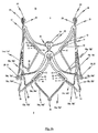
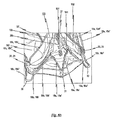
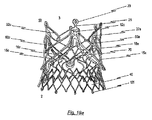
図1dは、心臓弁狭窄または心臓弁不全症を治療するための体内プロテーゼ1の側面斜視図である。体内プロテーゼ1は、本発明の第1実施形態に係る弁プロテーゼ100を保持する心臓弁ステント10を備える。図2dは、同様に、心臓弁狭窄または心臓弁不全症を治療するための別の体内プロテーゼ1の側面斜視図であり、本発明の第2実施形態に係る心臓弁ステント10が採用される。   FIG. 1d is a side perspective view of an endoprosthesis 1 for treating heart valve stenosis or heart valve insufficiency. The endoprosthesis 1 includes a heart valve stent 10 that holds the valve prosthesis 100 according to the first embodiment of the present invention. FIG. 2d is also a side perspective view of another endoprosthesis 1 for treating heart valve stenosis or heart valve insufficiency, employing a heart valve stent 10 according to a second embodiment of the present invention.

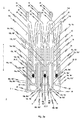
以下の説明は、本発明の好適な実施形態を詳細に説明するための図面を参照して行われる。本発明の特定の実施形態に係る心臓弁ステント10(以下、単に「ステント」と呼ぶ)は、ステント10が折り畳まれた状態である第1の予め定義された形状から、ステント10が拡張された状態である第2の予め定義された形状に変形可能な拡張構造を有する。図1aは、本発明の第1実施形態に係るステント10の側面図であり、ステント10が折り畳まれた状態である。図2aは、本発明の第2実施形態に係る折り畳まれたステント10を示す。   The following description is made with reference to the drawings for describing preferred embodiments of the present invention in detail. A heart valve stent 10 (hereinafter simply referred to as a “stent”) according to a specific embodiment of the present invention is obtained by expanding the stent 10 from a first predefined shape in which the stent 10 is folded. An expansion structure that is deformable to a second predefined shape in a state. FIG. 1 a is a side view of the stent 10 according to the first embodiment of the present invention, in a state where the stent 10 is folded. FIG. 2a shows a folded stent 10 according to a second embodiment of the present invention.

二つの実施形態において、ステント10とステントに取り付けられた弁プロテーゼは、挿入カテーテルシステム(図には明示せず)を使用して第1の形状(図1aおよび図2aを参照)で患者の体内に低侵襲的に挿入される。挿入の間は、ステント10に固定された弁プロテーゼ100も同様に折り畳まれた状態である。しかしながら、明瞭さのために、図1aと図2aの両方とも、ステント10に固定された弁プロテーゼ100の表示が省かれている。   In two embodiments, the stent 10 and the valve prosthesis attached to the stent are in a first configuration (see FIGS. 1a and 2a) using an insertion catheter system (not explicitly shown) in the patient's body. Inserted in a minimally invasive manner. During the insertion, the valve prosthesis 100 fixed to the stent 10 is also folded. However, for clarity, both FIGS. 1 a and 2 a omit the representation of the valve prosthesis 100 secured to the stent 10.

患者の心臓に移植部位に到達すると、ステント10は拡張された形状に変形する。ステント10に固定された弁プロテーゼ100も展開し拡張される。ステント10の拡張された形状は、プログラミングによって設定された恒久的な形状である。完全に展開し拡張された弁プロテーゼ100が同様に固定された、本発明の第1/第2実施形態に係る完全に拡張されたステント10が、図1dおよび図2dに示されている。ステント10の第2形状、すなわち完全に拡張したが移植されていない状態のステント10の形状が、完全に拡張し移植された状態のステント10の形状と異なっていてもよい点に注意するのが重要である。なぜなら、移植された状態では、完全に拡張したステント10の形状は、移植部位における生体構造によって少なくとも部分的に制限されるからである。   Upon reaching the implantation site in the patient's heart, the stent 10 deforms into an expanded shape. The valve prosthesis 100 secured to the stent 10 is also deployed and expanded. The expanded shape of the stent 10 is a permanent shape set by programming. A fully expanded stent 10 according to the first / second embodiment of the present invention, in which the fully deployed and expanded valve prosthesis 100 is similarly secured, is shown in FIGS. 1d and 2d. It should be noted that the second shape of stent 10, that is, the shape of stent 10 in a fully expanded but unimplanted state, may be different from the shape of stent 10 in a fully expanded and implanted state. is important. This is because in the implanted state, the shape of the fully expanded stent 10 is at least partially limited by the anatomy at the implantation site.

図1bおよび図1cは、弁プロテーゼ100が除かれた異なる視点からの本発明の第1実施形態に係る完全に拡張されたステント10を示す。図2bおよび図2cは、同様に弁プロテーゼ100が除かれた異なる視点からの本発明の第2実施形態に係る完全に拡張されたステント10を示す。   1b and 1c show a fully expanded stent 10 according to a first embodiment of the present invention from a different point of view, with the valve prosthesis 100 removed. 2b and 2c show a fully expanded stent 10 according to a second embodiment of the present invention from a different point of view, with the valve prosthesis 100 removed as well.

以下、ステント10の第1実施形態の説明において図1aから図1eを最初に参照する。   Reference is first made to FIGS. 1a to 1e in the description of the first embodiment of the stent 10.

第1実施形態に係るステント10は、チューブ、特に金属管の一部から一体的に切断された構造をしている。ステント10の設計を形作るために使用された切断パターンが、図1eの二次元投影図の中に描かれている。   The stent 10 according to the first embodiment has a structure that is integrally cut from a part of a tube, particularly a metal tube. The cutting pattern used to shape the stent 10 design is depicted in the two-dimensional projection of FIG. 1e.

詳細には、ステント10は、ステントを肺動脈弁または大動脈弁の平面内に自ら位置決めさせる機能を担う三つの位置決めアーチ15a、15b、15cを有する。位置決めアーチ15a、15b、15cは、心臓の移植部位(図18a参照)においてステント10を位置決めする間、治療対象の(病変した)心臓弁の嚢(pocket)Tに係合する丸まったヘッド部20を有する。   Specifically, the stent 10 has three positioning arches 15a, 15b, 15c that serve to position the stent itself in the plane of the pulmonary or aortic valve. The positioning arches 15a, 15b, 15c are rounded head portions 20 that engage the pocket T of the (lesioned) heart valve to be treated while positioning the stent 10 at the heart implantation site (see FIG. 18a). Have

生体弁のものと一致する対称性を提供する他、三つの位置決めアーチ15a、15b、15cは回転の精度、回転対称性および回転安定性を提供する。当然ながら、ステント10は全部で三つの位置決めアーチの使用に限定されるものではない。   In addition to providing symmetry consistent with that of a biological valve, the three positioning arches 15a, 15b, 15c provide rotational accuracy, rotational symmetry and rotational stability. Of course, the stent 10 is not limited to the use of all three positioning arches.

それぞれがステント10の下端2の方を向く位置決めアーチ15a、15b、15cのヘッド部20は、位置決めアーチ15a、15b、15cが置換される心臓弁Hの嚢Tに係合するときに血管壁が損傷しないように丸くされている。ステント10の移植中の移動及び位置の分析を改善するため、位置決めアーチ15a、15b、15cのヘッド部20上にまたはその内部に基準マーカ21が設けられる。赤外線または超音波によって活性化可能な放射線を通さない(radio opaque)マーカが特に適している。   The head portions 20 of the positioning arches 15a, 15b, 15c, each facing the lower end 2 of the stent 10, engage the vessel wall when the positioning arches 15a, 15b, 15c are engaged with the sac T of the heart valve H to be replaced. It is rounded to prevent damage. In order to improve the movement and position analysis during implantation of the stent 10, a fiducial marker 21 is provided on or within the head portion 20 of the positioning arch 15a, 15b, 15c. Particularly suitable are radio opaque markers that can be activated by infrared or ultrasound.

位置決めアーチ15a、15b、15cはそれぞれ、ステント10の下端で閉鎖する本質的にU字形またはV字形の構造を呈する。したがって、各位置決めアーチ15a、15b、15cは、関連する位置決めアーチ15a、15b、15cのヘッド部20からステント10の上端3に向けてそれぞれ延び出す全部で二つのアーム(腕部)15a’、15a”、15b’、15b”、15c’、15c”を有する。そうすることで、二つの隣合う位置決めアーチのそれぞれの隣接するアームが、接続部22を介して互いに接続される。   The positioning arches 15a, 15b, 15c each have an essentially U-shaped or V-shaped structure that closes at the lower end of the stent 10. Accordingly, each positioning arch 15a, 15b, 15c has a total of two arms (arms) 15a ', 15a extending from the head portion 20 of the associated positioning arch 15a, 15b, 15c toward the upper end 3 of the stent 10, respectively. ", 15b ', 15b", 15c', 15c ". In this way, the adjacent arms of each of the two adjacent positioning arches are connected to each other via the connection 22.

適切なカテーテルシステムを用いてステント10およびステントに取り付けられた弁プロテーゼを移植および外植するため、ステント10はその上端3にカテーテル保持手段23を備えている。接続部22はそれぞれ、接続ウェブ25を介してカテーテル保持手段23と接続される。接続ウェブ25は、以下では「第2接続ウェブ25」と呼ばれる。   In order to implant and explant the stent 10 and the valve prosthesis attached to the stent using a suitable catheter system, the stent 10 is provided with a catheter holding means 23 at its upper end 3. Each of the connecting portions 22 is connected to the catheter holding means 23 via the connecting web 25. The connection web 25 is hereinafter referred to as “second connection web 25”.

カテーテル保持手段23は、それぞれが対応する長円形の小穴24を有する長円形のヘッド部を備える。カテーテル保持手段23の形状は、ステント10の移植/外植に使用されるカテーテルシステムのカテーテルの先端のクラウンを補完する。カテーテル先端のクラウンは、カテーテル保持手段23の負側として構成された突出要素を有する。代替的には、突出要素が小穴24の補完的な形状であり、カテーテル保持ヘッドとして構成される。これは、ステント10の上部領域3と解放可能に係合するようにクラウンの突出要素を形成し、カテーテル先端にステント10を解放可能に取り付けることで実現可能である。   The catheter holding means 23 includes an oval head portion having an oval small hole 24 corresponding to each. The shape of the catheter holding means 23 complements the crown of the catheter tip of the catheter system used to implant / explant the stent 10. The crown of the catheter tip has a protruding element configured as the negative side of the catheter holding means 23. Alternatively, the protruding element is complementary to the eyelet 24 and is configured as a catheter holding head. This can be accomplished by forming a crown protruding element to releasably engage the upper region 3 of the stent 10 and releasably attaching the stent 10 to the catheter tip.

第1接続ウェブ17は、ステント10の長手方向Lに本質的に延出し、上端部17dと下端部17pとを有する。上端部17dは、上述した第2接続ウェブ25に加えて、二つの隣合う位置決めアーチ15a、15b、15cの二つのアーム15a’、15a”、15b’、15b”、15c’、15c”の間の接続部22の中に開く。図1bから分かるように、第1接続ウェブ17は本質的に逆Y字形の構成を有し、その下端部17pで分岐して二つの隣合う保持アーチ16a、16b、16cのそれぞれのアーム16a’、16a”、16b’、16b”、16c’、16c”に道を譲る。   The first connection web 17 essentially extends in the longitudinal direction L of the stent 10 and has an upper end portion 17d and a lower end portion 17p. In addition to the second connecting web 25 described above, the upper end 17d is formed between two arms 15a ′, 15a ″, 15b ′, 15b ″, 15c ′, 15c ″ of two adjacent positioning arches 15a, 15b, 15c. 1b, the first connecting web 17 has an essentially inverted Y-shaped configuration, branching off at its lower end 17p, and two adjacent holding arches 16a, Give way to each arm 16a ', 16a ", 16b', 16b", 16c ', 16c "of 16b, 16c.

それぞれの位置決めアーチ15と保持アーチ16の間には、締結アーチ(fastening arch)19がある。図1bに特に明瞭に示すように、締結アーチは締結部11の下端から延出し、ステント10の下端で閉鎖する実質的にU字形またはV字形の構造を有する。図1dに示されるように、締結アーチは弁プロテーゼ100の下端を支持する役割を果たす。プロテーゼ100は、締結アーチ19a、19b、19cが弁材料のポケット内に配置されるような形状とされる。   Between each positioning arch 15 and holding arch 16 is a fastening arch 19. As shown particularly clearly in FIG. 1 b, the fastening arch has a substantially U-shaped or V-shaped structure extending from the lower end of the fastening portion 11 and closing at the lower end of the stent 10. As shown in FIG. 1 d, the fastening arch serves to support the lower end of the valve prosthesis 100. The prosthesis 100 is shaped such that the fastening arches 19a, 19b, 19c are placed in a pocket of valve material.

このステント設計は軸対称の構造を実現し、各位置決めアーチ15a、15b、15cが一つの締結アーチ19a、19b、19cと一つの保持アーチ16a、16b、16cに割り当てられる。したがって、図1aから図1dに描かれた第1実施形態のステント10は、図1dに例示として描かれたように、弁プロテーゼ100を収容するためのステント10の保持セグメントを構成する全部で三つの保持アーチ16a、16b、16cを備える。   This stent design provides an axisymmetric structure, with each positioning arch 15a, 15b, 15c assigned to one fastening arch 19a, 19b, 19c and one holding arch 16a, 16b, 16c. Accordingly, the stent 10 of the first embodiment depicted in FIGS. 1a to 1d comprises a total of three constituting the retention segments of the stent 10 for accommodating the valve prosthesis 100, as depicted by way of example in FIG. 1d. Two holding arches 16a, 16b, 16c are provided.

ステント10が第1の(折り畳まれた)形状である、図1aに示すステント10の状態では、位置決めアーチ15a、15b、15cのそれぞれのアーム15a’、15a”、15b’、15b”、15c’、15c”は、締結アーチ19a、19b、19cのそれぞれのアーム19a’、19a”、19b’、19b”、19c’、19c”と直接隣接し、アーム19a’、19a”、19b’、19b”、19c’、19c”は関連する保持アーチ16a、16b、16cのそれぞれのアーム16a’、16a”、16b’、16b”、16c’、16c”と直接隣接する。   In the state of the stent 10 shown in FIG. 1a, where the stent 10 is in a first (folded) shape, the respective arms 15a ′, 15a ″, 15b ′, 15b ″, 15c ′ of the positioning arches 15a, 15b, 15c. , 15c ″ are directly adjacent to the respective arms 19a ′, 19a ″, 19b ′, 19b ″, 19c ′, 19c ″ of the fastening arches 19a, 19b, 19c, and the arms 19a ′, 19a ″, 19b ′, 19b ″. , 19c ′, 19c ″ are directly adjacent to the respective arms 16a ′, 16a ″, 16b ′, 16b ″, 16c ′, 16c ″ of the associated holding arch 16a, 16b, 16c.

第1実施形態に従ったステント10が第2の拡張された形状で示されている図1bを参照する。各位置決めアーチ15a、15b、15c、関連する締結アーチ19a、19b、19cおよび保持アーチ16a、16b、16cのそれぞれが、ステント10の下端2に向けて閉鎖する本質的にU字形またはV字形の構造を呈することが、この図から特に認識できる。具体的には、各位置決めアーチ15a、15b、15cは、関連する締結アーチ19a、19b、19cの本質的にU字形またはV字形の構造が取られたチューブの一部の材料片から切り出される。このことは、図1eに描かれた切断パターンから理解することができる。   Reference is made to FIG. 1b, in which a stent 10 according to a first embodiment is shown in a second expanded shape. Each positioning arch 15 a, 15 b, 15 c, associated fastening arch 19 a, 19 b, 19 c and retaining arch 16 a, 16 b, 16 c each has an essentially U-shaped or V-shaped structure that closes toward the lower end 2 of the stent 10. It can be particularly recognized from this figure that Specifically, each positioning arch 15a, 15b, 15c is cut from a piece of material that is part of a tube that has an essentially U-shaped or V-shaped configuration of the associated fastening arch 19a, 19b, 19c. This can be understood from the cutting pattern depicted in FIG.

図1aと図1bを比較すると、ステント10の拡張時、すなわちステント10が第1形状から第2形状に変形するとき、ステント10の長手方向Lの長さが短くなる一方、同時に断面が拡大することが分かる。ステント10の拡張状態では、位置決めアーチ15a、15b、15cは、ステント10の上端3と比較して、ステント10の下端2における半径方向でより大きく拡大する。半径方向により大きく突出するので、位置決めアーチ15a、15b、15cを、置換される心臓弁Hの心臓弁嚢Tの中に特に簡単な態様で展開することができる。   Comparing FIG. 1a and FIG. 1b, when the stent 10 is expanded, that is, when the stent 10 is deformed from the first shape to the second shape, the length in the longitudinal direction L of the stent 10 is shortened, while the cross section is enlarged simultaneously. I understand that. In the expanded state of the stent 10, the positioning arches 15 a, 15 b, 15 c expand more greatly in the radial direction at the lower end 2 of the stent 10 as compared to the upper end 3 of the stent 10. Since it projects more radially, the positioning arches 15a, 15b, 15c can be deployed in a particularly simple manner into the heart valve sac T of the heart valve H to be replaced.

ステント10の拡張状態時にステント10から半径方向に既に突出している位置決めアーチ15a、15b、15cのために、心臓の移植部位でステント10およびステントに取り付けられた弁プロテーゼの特定の固定が達成されているときでさえも、位置決めアーチ15a、15b、15cから血管壁に作用する接触力はステント10を移植部位にしっかりと固定するには不十分であることに注意する。ステント10の下端2を形成する上述した保持アーチ16a、16b、16cは、この理由のために設けられている。保持アーチ16a、16b、16cは、拡張状態時にステント10の周囲から半径方向に突出し、その結果、保持アーチ16a、16b、16cは半径方向に作用する接触力を持ってステントの展開される血管壁を押しつける。加えて、保持アーチ16a、16b、16cの閉鎖端部が外方に広がり、ステント10の周囲からさらに半径方向に突出する。この形状により、保持アーチ16a、16b、16cの端部を生体弁輪(native valve annulus )の下方に位置づけるか、または少なくとも生体弁輪の上に位置づけることが可能になり、これによってステント10およびステントに取り付けられた弁プロテーゼがさらに固定される。   Due to the positioning arches 15a, 15b, 15c already protruding radially from the stent 10 when the stent 10 is expanded, a specific fixation of the stent 10 and the valve prosthesis attached to the stent is achieved at the heart implantation site. Note that the contact force acting on the vessel wall from the positioning arches 15a, 15b, 15c is insufficient to secure the stent 10 firmly at the implantation site, even when in contact. The retaining arches 16a, 16b, 16c described above that form the lower end 2 of the stent 10 are provided for this reason. The retaining arches 16a, 16b, 16c project radially from the periphery of the stent 10 in the expanded state, so that the retaining arches 16a, 16b, 16c have a radially acting contact force and the vessel wall where the stent is deployed. Press. In addition, the closed ends of the retention arches 16a, 16b, 16c extend outward and protrude further radially from the periphery of the stent 10. This shape allows the ends of the retention arches 16a, 16b, 16c to be positioned below the native valve annulus, or at least above the biological annulus, thereby providing the stent 10 and stent. A valve prosthesis attached to the is further secured.

保持アーチ16a、16b、16cに加えて、ステント10は補助アーチ(auxiliary arch)18a、18b、18cをさらに備える。補助アーチ18a、18b、18cは、ステント10の移植部位で血管壁に対して半径方向に作用する接触力を同様に及ぼし、これによって移植部位におけるステント10およびステントに取り付けられた弁プロテーゼの固定がさらに改善される。   In addition to the retention arches 16a, 16b, 16c, the stent 10 further comprises auxiliary arches 18a, 18b, 18c. The auxiliary arches 18a, 18b, 18c similarly exert a contact force acting radially on the vessel wall at the site of implantation of the stent 10 to thereby secure the stent 10 and the valve prosthesis attached to the stent at the site of implantation. Further improvement.

図1bから分かるように、ステント10は、ステント10の下端2に向けて閉鎖する全部で三つの本質的にU字形またはV字形の補助アーチ18a、18b、18cを備える。各補助アーチ18a、18b、18cは、第1の保持アーチ16a、16b、16cを、第1の保持アーチと隣合う第2の保持アーチと接続する。   As can be seen from FIG. 1 b, the stent 10 comprises a total of three essentially U-shaped or V-shaped auxiliary arches 18 a, 18 b, 18 c that close towards the lower end 2 of the stent 10. Each auxiliary arch 18a, 18b, 18c connects the first holding arch 16a, 16b, 16c with a second holding arch adjacent to the first holding arch.

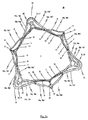
拡張されたステント10の下端領域2の上面図(図1c参照)では、下端領域2は、保持アーチ16a、16b、16cの個々のアーム16a’、16a”、16b’、16b”、16c’、16c”および補助アーチ18a、18b、18cの個々のアーム18a’、18a”、18b’、18b”、18c’、18c”から形成された、12角形の多角形構造を呈する。このステント設計は、特に、ステント10の下端領域2の周りに一様に分布した全部で6つのアーチ16a、16b、16c、18a、18b、18cを提供する。アーチのそれぞれは血管壁を押しつけ、ステント10が拡張され移植された状態においてステント10およびステントに取り付けられた弁プロテーゼを効果的に適切な位置に保持する。   In a top view of the lower end region 2 of the expanded stent 10 (see FIG. 1c), the lower end region 2 includes the individual arms 16a ′, 16a ″, 16b ′, 16b ″, 16c ′ of the holding arches 16a, 16b, 16c, 16c ″ and the individual arms 18a ′, 18a ″, 18b ′, 18b ″, 18c ′, 18c ″ of the auxiliary arches 18a, 18b, 18c exhibit a dodecagonal polygonal structure. This stent design in particular provides a total of six arches 16a, 16b, 16c, 18a, 18b, 18c that are uniformly distributed around the lower end region 2 of the stent 10. Each of the arches presses against the vessel wall, effectively holding the stent 10 and the valve prosthesis attached to the stent in place when the stent 10 is expanded and implanted.

要約すると、一方で保持アーチ16a、16b、16cを設け、他方で補助アーチ18a、18b、18cを設けることで、これらのアーチのそれぞれの下端部によって血管壁に半径方向の力が及ぼされる。これにより、ステント10に固定された弁プロテーゼ100の血管壁に対する強固な封止と、心臓の移植部位におけるステント10のしっかりとした固定の両方を確実に行うことができる。   In summary, by providing the holding arches 16a, 16b, 16c on the one hand and the auxiliary arches 18a, 18b, 18c on the other hand, a radial force is exerted on the vessel wall by the lower end of each of these arches. Thereby, both the strong sealing with respect to the blood vessel wall of the valve prosthesis 100 fixed to the stent 10 and the firm fixation of the stent 10 at the implantation site of the heart can be reliably performed.

保持アーチ16a、16b、16cおよび補助アーチ18a、18b、18cによって血管壁に及ぼされる接触力に加えて、ステント10が完全に拡張したが移植されていない状態のときに、ステント10の上端領域3を下端領域2と比較して半径方向に10%から25%だけ大きく拡張させることも考えられる。こうすると、ステント10は、下端領域2に向けて先細であるわずかに凹形の構造となる。しかしながら、移植された状態のステントの形状は移植側の生体組織によって制限されるので、完全に拡張し移植された状態では、ステント10の上端部3は下端領域2と比較して10%から25%だけ半径方向に拡張されないことがある。しかしながら、ステント10の上端部3は、ステント10の制約を受ける下端部2の環の直径と比較して、やや半径方向に広がる傾向にある。これにより、血管壁を押しつけるステント10の上端領域2によってステント10が血管内にしっかりと固定される。   In addition to the contact force exerted on the vessel wall by the retention arches 16a, 16b, 16c and the auxiliary arches 18a, 18b, 18c, the upper end region 3 of the stent 10 when the stent 10 is fully expanded but not implanted. It is also conceivable that the width is expanded by 10% to 25% in the radial direction compared with the lower end region 2. In this way, the stent 10 has a slightly concave structure that tapers towards the lower end region 2. However, since the shape of the stent in the implanted state is limited by the living tissue on the implantation side, the upper end portion 3 of the stent 10 is 10% to 25% compared to the lower end region 2 in the completely expanded and implanted state. % May not expand radially. However, the upper end portion 3 of the stent 10 tends to expand slightly in the radial direction as compared with the diameter of the ring of the lower end portion 2 that is restricted by the stent 10. Thereby, the stent 10 is firmly fixed in the blood vessel by the upper end region 2 of the stent 10 that presses against the blood vessel wall.

ステント10およびステントに取り付けられた弁プロテーゼが中に展開された心臓および血管の蠕動運動の間でさえも、ステント10に固定された弁プロテーゼのステント10に対する縦方向の変位が確実に最小となるように、図面に示された本発明のステント10の実施形態は、ステント10の長手方向Lに延び、弁プロテーゼ100の組織部分をステント10に固定する手段である複数の締結部11をステント10に備えている。心臓弁狭窄または心臓弁不全症を治療するための体内プロテーゼ1の側面斜視図である図1dを参照する。体内プロテーゼ1は、本発明の第1実施形態にしたがった、弁プロテーゼ100を保持するステント10を備える。弁プロテーゼ100は、生体材料または合成材料で作られた少なくとも一つの弁尖102を備える。   Even during the peristaltic movement of the heart and blood vessels in which the stent 10 and the valve prosthesis attached thereto are deployed, the longitudinal displacement of the valve prosthesis fixed to the stent 10 with respect to the stent 10 is reliably minimized. Thus, the embodiment of the stent 10 of the present invention shown in the drawings includes a plurality of fastening portions 11 that extend in the longitudinal direction L of the stent 10 and are means for securing the tissue portion of the valve prosthesis 100 to the stent 10. In preparation. Reference is made to FIG. 1d, which is a side perspective view of an endoprosthesis 1 for treating heart valve stenosis or heart valve insufficiency. The endoprosthesis 1 includes a stent 10 that holds a valve prosthesis 100 according to a first embodiment of the present invention. The valve prosthesis 100 comprises at least one leaflet 102 made of biomaterial or synthetic material.

ブタやウマなどの動物から除去された生体弁、心膜などの結合組織から作成された人工の生体弁、細胞培養で育成された組織、ニチノールなどの人工材料および人工繊維を含む、任意の適切な材料で弁プロテーゼを作成できることは認められよう。   Any suitable, including biological valves removed from animals such as pigs and horses, artificial biological valves made from connective tissue such as pericardium, tissue grown in cell culture, artificial materials such as nitinol and artificial fibers It will be appreciated that the valve prosthesis can be made of any material.

詳細には、ステント10の第1接続ウェブ17は、上端17dを介して接続部22と接続し、下端17pを介して締結部11の上端13と接続する。一つのおよび同一の接続ウェブ17と接続された締結部の下端14はそれぞれ、ステント10の下端2に向けて閉鎖する本質的にU字形またはV字形の補助アーチ18a、18b、18cを介して互いに接続される。   Specifically, the first connection web 17 of the stent 10 is connected to the connection portion 22 via the upper end 17d and is connected to the upper end 13 of the fastening portion 11 via the lower end 17p. The lower ends 14 of the fasteners connected to one and the same connecting web 17 are respectively connected to each other via essentially U-shaped or V-shaped auxiliary arches 18a, 18b, 18c that close towards the lower end 2 of the stent 10. Connected.

具体的には、本発明の第1実施形態のステント10の拡張された状態が図1dに示されており、ここではステント10によって引き伸ばされた糸101または細いワイヤによって弁プロテーゼ100が上記ステント10に固定されている。弁プロテーゼ100が配置されたステント10の中央領域および下端領域2を拡大することで、体内プロテーゼの展開が実現されることは容易に理解される。同時に、保持アーチ16a、16b、16cおよび補助アーチ18a、18b、18cの下端部が、(図1dに不図示の)血管壁に半径方向の力を及ぼす。   Specifically, an expanded state of the stent 10 of the first embodiment of the present invention is shown in FIG. 1d, where the valve prosthesis 100 is connected to the stent 10 by a thread 101 or a thin wire stretched by the stent 10. It is fixed to. It will be readily understood that deployment of the endoprosthesis is achieved by enlarging the central and lower end regions 2 of the stent 10 where the valve prosthesis 100 is located. At the same time, the lower ends of the holding arches 16a, 16b, 16c and the auxiliary arches 18a, 18b, 18c exert a radial force on the vessel wall (not shown in FIG. 1d).

図1dから理解できるように、ステント10のそれぞれの締結部11内に規定の複数の締結穴12が構成されており、これらが締結部11に沿った予め定められた長手方向位置に分布するように配置されている。弁プロテーゼ100の組織部分をステント10に固定する糸101または細いワイヤは、それぞれの締結穴12を通して導かれる。   As can be understood from FIG. 1 d, a plurality of prescribed fastening holes 12 are configured in each fastening portion 11 of the stent 10, so that these are distributed at predetermined longitudinal positions along the fastening portion 11. Is arranged. The thread 101 or thin wire that secures the tissue portion of the valve prosthesis 100 to the stent 10 is guided through the respective fastening hole 12.

体内プロテーゼ1を構成する部品、すなわちステント10と弁プロテーゼ100の両方が、外科的処置の直前まで互いに接続されなくてもよい。そのように構成された体内プロテーゼ1は、弁プロテーゼ100の組織の構造的劣化を起こすことなく、拡張された形状で長期間保存することができる。外科的処置の直前に体内プロテーゼ1を圧縮して折り畳み形状にされる。続いて、体内プロテーゼ1は、体内プロテーゼ1の移植に用いられるカテーテルシステム内に挿入される準備ができる。   The components that make up the endoprosthesis 1, ie, both the stent 10 and the valve prosthesis 100, may not be connected to each other until just prior to the surgical procedure. The thus configured endoprosthesis 1 can be stored for a long time in an expanded shape without causing structural deterioration of the tissue of the valve prosthesis 100. Immediately prior to the surgical procedure, the endoprosthesis 1 is compressed into a folded shape. Subsequently, the endoprosthesis 1 is ready for insertion into a catheter system used for implantation of the endoprosthesis 1.

当然、体内プロテーゼ1を構成する部品、すなわちステント10と弁プロテーゼ100の両方が、外科的処置の直前まで接続されないことも想定可能である。この場合、ステント10は第2の形状、すなわち拡張された状態で保存され、外科的処置の直前まで第1の(折り畳まれた)形状にされない。   Of course, it is possible to envisage that the components that make up the endoprosthesis 1, ie both the stent 10 and the valve prosthesis 100, are not connected until just before the surgical procedure. In this case, the stent 10 is stored in the second shape, ie, expanded, and is not in the first (folded) shape until just prior to the surgical procedure.

図1bおよび図1dから、それぞれの締結部11が、ステント10の保持アーチ16a、16b、16cのそれぞれのアーム16a’、16a”、16b’、16b”、16c’、16c”内に構成されることが分かる。締結部11内に構成される締結穴12の大きさは、弁プロテーゼ100の組織部分をステント10に締結するために使用される糸101またはワイヤの太さに適合させるべきである。   From FIGS. 1b and 1d, the respective fastening portions 11 are configured in the respective arms 16a ′, 16a ″, 16b ′, 16b ″, 16c ′, 16c ″ of the retaining arches 16a, 16b, 16c of the stent 10, respectively. It can be seen that the size of the fastening hole 12 configured in the fastening portion 11 should be adapted to the thickness of the thread 101 or wire used to fasten the tissue portion of the valve prosthesis 100 to the stent 10. .

締結穴12の断面形状も、弁プロテーゼ100の締結に使用される糸101またはワイヤの断面形状に適合させてもよい。これにより、ステント10に対して予め定められた正確な位置に弁プロテーゼ100を固定することができる。弁プロテーゼ100をステント10に固定するために複数の締結穴12を設けることによって、ステント10への弁プロテーゼ100正確な位置決めが実現される。   The cross-sectional shape of the fastening hole 12 may also be adapted to the cross-sectional shape of the thread 101 or wire used for fastening the valve prosthesis 100. As a result, the valve prosthesis 100 can be fixed at a predetermined accurate position with respect to the stent 10. By providing a plurality of fastening holes 12 to secure the valve prosthesis 100 to the stent 10, accurate positioning of the valve prosthesis 100 on the stent 10 is achieved.

締結穴12は、弁プロテーゼ100をステント10に固定するために使用される糸101またはワイヤの太さおよび/または断面形状に適合されているので、体内プロテーゼ1が移植されるとき、心臓の蠕動運動に起因するステント10と弁プロテーゼ100との間の相対移動を効果的に防ぐことができる。体内プロテーゼ1が完全に拡張して移植された状態にあるとき、弁プロテーゼ100は、弁プロテーゼの固定に使用される糸101またはワイヤの摩擦で引き起こされる摩耗が最小化されるような、最小限の遊びでステント10に締結される。   The fastening hole 12 is adapted to the thickness and / or cross-sectional shape of the thread 101 or wire used to secure the valve prosthesis 100 to the stent 10 so that when the endoprosthesis 1 is implanted, the heart is peristalized. Relative movement between the stent 10 and the valve prosthesis 100 due to movement can be effectively prevented. When the endoprosthesis 1 is in a fully expanded and implanted state, the valve prosthesis 100 is such that the wear caused by the friction of the thread 101 or wire used to secure the valve prosthesis is minimized. It is fastened to the stent 10 by play.

弁組織、すなわち弁プロテーゼ100の組織部分がステント10にしっかりと締結されるが、弁組織は、折り畳まれるときにステントが伸びるようにして損傷を与えることなく変形できるようなものでなければならない。   Although the valve tissue, i.e., the tissue portion of the valve prosthesis 100, is securely fastened to the stent 10, the valve tissue must be such that it can be deformed without damage as it is stretched when folded.

上述したように、それぞれの締結部11内に構成された締結穴12は、弁プロテーゼ100をステント10に固定するために使用される糸101の直径に応じて、および/または弁プロテーゼ100の組織部分をステント10に固定するために利用される縫製技術に応じて、直径、数または断面形状(長円形、四角形など)が異なっていてもよい。少なくとも一つの締結穴12の直径、数および/または断面形状は、体内プロテーゼ1(すなわち、心臓弁狭窄および/または心臓弁不全症の治療に用いられる医療機器)の種類の表示としての役割を果たしてもよい。この点において、少なくとも一つの締結穴12の直径、数および/または断面形状を、ステント10に固定されるように適合された弁プロテーゼ100の異なるサイズまたは種類を区別するための表示として使用してもよいし、あるいは、弁プロテーゼ100が既にステント10に固定されている場合、体内プロテーゼ1の異なるサイズまたは種類を区別するための表示として使用してもよい。例えば、ステントに固定された小さいサイズの弁プロテーゼ100を有する小さなサイズのステント10、あるいは小さなサイズの弁プロテーゼ100を運ぶように適合され構成された小さなサイズのステント10は、円形の締結穴12を有してもよく、一方、ステントに固定された大きなサイズの弁プロテーゼ100を有する大きなサイズのステント10、あるいは大きなサイズの弁プロテーゼ100を運ぶように適合され構成された大きなサイズのステント10は、三角形の締結穴12を有してもよい。これにより、執刀医/心臓スタッフが、測定の必要なしに、異なる弁のサイズ、ステントの種類、および/または弁プロテーゼの種類を簡単にかつ視覚的に見分けることが可能になる。   As described above, the fastening holes 12 configured in each fastening portion 11 may depend on the diameter of the thread 101 used to secure the valve prosthesis 100 to the stent 10 and / or the tissue of the valve prosthesis 100. Depending on the sewing technique utilized to secure the portion to the stent 10, the diameter, number or cross-sectional shape (eg, oval, square, etc.) may vary. The diameter, number and / or cross-sectional shape of the at least one fastening hole 12 serves as an indication of the type of endoprosthesis 1 (ie, a medical device used to treat heart valve stenosis and / or heart valve insufficiency). Also good. In this regard, the diameter, number and / or cross-sectional shape of the at least one fastening hole 12 is used as an indication to distinguish different sizes or types of valve prostheses 100 adapted to be secured to the stent 10. Alternatively, if the valve prosthesis 100 is already secured to the stent 10, it may be used as an indicator to distinguish between different sizes or types of the endoprosthesis 1. For example, a small sized stent 10 having a small sized valve prosthesis 100 secured to the stent, or a small sized stent 10 adapted and configured to carry a small sized valve prosthesis 100 may have a circular fastening hole 12. A large size stent 10 having a large size valve prosthesis 100 secured to the stent, or a large size stent 10 adapted and configured to carry a large size valve prosthesis 100, A triangular fastening hole 12 may be provided. This allows the surgeon / cardiac staff to easily and visually distinguish between different valve sizes, stent types, and / or valve prosthesis types without the need for measurements.

図1a〜eに示す第1実施形態では、ステント10の締結部11(その上に弁プロテーゼ100が縫製されるか縫製可能である)は、ステント10が圧縮されるとき、例えばステント10が図1aに示す第1の(折り畳まれた)形状であるときに、自身の形状を変化させない。この事象は、標準のチューブ状ステントが使用されるときに発生する。したがって、糸が摩耗するリスクは最小限になる。   In the first embodiment shown in FIGS. 1 a-e, the fastening portion 11 of the stent 10 (on which the valve prosthesis 100 can be sewn or sewn) can be used when the stent 10 is compressed, for example When it is the first (folded) shape shown in 1a, it does not change its shape. This event occurs when a standard tubular stent is used. Thus, the risk of thread wear is minimized.

しかしながら、本発明の第16および第17実施形態で詳細に説明するように、保持アーチと、保持アーチの各アームに設けられる締結部とは、ステント10が折り畳まれるときにその形状が変化しないように構成されてもよい。詳細には、本発明のステント設計の第16および第17実施形態によると、ステントが拡張されるとき保持アーチは曲がっているが、ステントが折り畳まれているときには相対的に直線である。   However, as will be described in detail in the sixteenth and seventeenth embodiments of the present invention, the shape of the holding arch and the fastening portion provided on each arm of the holding arch does not change when the stent 10 is folded. May be configured. Specifically, according to the sixteenth and seventeenth embodiments of the stent design of the present invention, the retention arch is bent when the stent is expanded, but is relatively straight when the stent is folded.

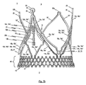
第2実施形態に係るステント10が図2aから図2cに描かれており、これは図1aから図1cに示したステント10の第1実施形態と構造および機能が類似している。図1eに係る切断パターンと原則として同等である、図2eに示す切断パターンにも同様のことが当てはまる。したがって、共通する特徴の詳細な説明は省略される。     A stent 10 according to a second embodiment is depicted in FIGS. 2a to 2c, which is similar in structure and function to the first embodiment of the stent 10 shown in FIGS. 1a to 1c. The same applies to the cutting pattern shown in FIG. 2e, which is in principle equivalent to the cutting pattern according to FIG. 1e. Therefore, detailed description of common features is omitted.

相違点は、ステント10の上端3に設けられたカテーテル保持手段23の構成に見られる。本発明の第1実施形態のステント10と対照的に、本質的に丸い構成のヘッド部が第2実施形態におけるカテーテル保持手段23として使用されており、いずれの場合も本質的に長円形の小穴24が設けられている。ヘッド部の丸い構成のために、損傷または障害を与える危険性が低下する。それゆえ、ヘッド部の本質的に丸い構成はより傷つけないようになっている(atraumatic)。   The difference is seen in the configuration of the catheter holding means 23 provided at the upper end 3 of the stent 10. In contrast to the stent 10 of the first embodiment of the present invention, an essentially rounded head is used as the catheter retaining means 23 in the second embodiment, in each case an essentially oval eyelet. 24 is provided. Due to the round configuration of the head, the risk of damage or obstruction is reduced. Therefore, the essentially round configuration of the head is less traumatic (atraumatic).

既に示したように、本発明の特定の実施形態に係るステント10は、チューブの一部から、特に金属管から一体的に切断された構造を呈する。締結アーチ19a、19b、19cおよび保持アーチ16a、16b、16cが、各位置決めアーチ15a、15b、15cに割り当てられており、各保持アーチ16a、16b、16cは補助アーチ18a、18b、18cによって隣合う保持アーチと接続される。特定の数の締結穴12を有する締結部11が、保持アーチ16a、16b、16cの各アーム16a’、16a”、16b’、16b”、16c’、16c”内に構成される。   As already indicated, the stent 10 according to certain embodiments of the invention exhibits a structure that is integrally cut from a portion of the tube, particularly from a metal tube. Fastening arches 19a, 19b, 19c and holding arches 16a, 16b, 16c are assigned to each positioning arch 15a, 15b, 15c, and each holding arch 16a, 16b, 16c is adjacent by auxiliary arches 18a, 18b, 18c Connected with holding arch. A fastening portion 11 having a specific number of fastening holes 12 is configured in each arm 16a ', 16a ", 16b', 16b", 16c ', 16c "of the holding arch 16a, 16b, 16c.

図1eおよび図2eはそれぞれ、本発明の第1または第2実施形態に従ったステント10の展開図を示す。これらの展開図はそれぞれ、本発明の第1または第2実施形態に従ったステント10の製造に使用可能である切断パターンの二次元投影図に対応する。これにより、チューブの一部、特に金属管から一体的なステント10を切り出すことが可能になる。一方では、本発明のステント10は、ステント10の個々の部品(位置決めアーチ、保持アーチ、補助アーチ)の間の固定ジョイントまたは他の類似の接続デバイスを省略している。他方では、位置決めアーチ15a、15b、15cによって提供されるような位置決め機能と、保持アーチ16a、16b、16cの各アーム16a’、16a”、16b’、16b”、16c’、16c”内に構成された締結穴11によって提供されるような弁プロテーゼ100の規定の締結の機能とが、長手方向の広がりが最小限であるステント10に与えられる。   FIGS. 1e and 2e each show an exploded view of the stent 10 according to the first or second embodiment of the present invention. Each of these developments corresponds to a two-dimensional projection of a cutting pattern that can be used to manufacture the stent 10 according to the first or second embodiment of the present invention. This makes it possible to cut the integral stent 10 from a portion of the tube, in particular from a metal tube. On the one hand, the stent 10 of the present invention omits fixed joints or other similar connection devices between the individual parts of the stent 10 (positioning arch, holding arch, auxiliary arch). On the other hand, the positioning function as provided by the positioning arches 15a, 15b, 15c and the construction within each arm 16a ', 16a ", 16b', 16b", 16c ', 16c "of the holding arches 16a, 16b, 16c The defined fastening function of the valve prosthesis 100 as provided by the formed fastening holes 11 is provided to the stent 10 with minimal longitudinal spread.

保持アーチ16a、16b、16cに加えて、ステント10は、心臓の移植部位にステント10を特にしっかりと固定可能にする補助アーチ18a、18b、18cをさらに備える。   In addition to the retention arches 16a, 16b, 16c, the stent 10 further comprises auxiliary arches 18a, 18b, 18c that allow the stent 10 to be secured particularly securely at the heart implantation site.

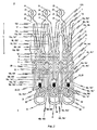
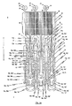
本発明の第3実施形態に係るステント10も、チューブの一部、特に金属管から切り出された一体構造を有する。ステント設計を形成するために使用される切断パターンが、図3の二次元投影図に示される。   The stent 10 according to the third embodiment of the present invention also has an integral structure cut out from a part of the tube, particularly from a metal tube. The cutting pattern used to form the stent design is shown in the two-dimensional projection of FIG.

ステントの第3実施形態と第1および第2実施形態との間の相違点は、図3に示す二次元の切断パターンの参照によって理解することができる。第1または第2実施形態の場合のように、ステント10の第三実施形態は、全部で三つの位置決めアーチ15a、15b、15cを有している。位置決めアーチは、肺動脈弁または大動脈弁の平面内に心臓弁ステントを自動的に位置決めする機能を引き受ける。   The differences between the third embodiment of the stent and the first and second embodiments can be understood by reference to the two-dimensional cutting pattern shown in FIG. As in the first or second embodiment, the third embodiment of the stent 10 has a total of three positioning arches 15a, 15b, 15c. The positioning arch assumes the function of automatically positioning the heart valve stent in the plane of the pulmonary or aortic valve.

ステント10はニチノールから作られる。ステントが拡張された状態のとき、すなわち切替温度を越えて恒久的形状となったとき、図1b、図1d、図2bおよび図2dに示すように位置決めアーチが半径方向に広がるだけでなく同時にステント10の方向にわずかに凸状に曲がるとなるように、位置決めアーチ15a、15b、15cが製造時に適切な熱処理によって調整される。この手段により、位置決めアーチ15a、15b、15cのヘッド部20を理想的なかたちで拡張ステント10の長手軸Lと平行にすることが可能になる。結果として、心臓弁ステント10の移植の間、位置決めアーチ15a、15b、15cのヘッド部20を生体弁Hの嚢T(図12a参照)の中に特に容易に挿入することができる。とりわけ、位置決めアーチ15a、15b、15cを生体弁Hの嚢Tの中に挿入するときに周囲組織への損傷が最小となる。生体弁の弁尖を各アーチの底部で挟むことによって、位置決めアーチ15a、15b、15c生体弁の弁尖にさらにクリップ力を及ぼすことができる。   Stent 10 is made from Nitinol. When the stent is in an expanded state, i.e., when it is in a permanent shape beyond the switching temperature, the positioning arch not only radially expands as shown in FIGS. 1b, 1d, 2b and 2d, but at the same time The positioning arches 15a, 15b, 15c are adjusted by an appropriate heat treatment at the time of manufacture so as to bend in a slightly convex shape in the direction of 10. By this means, the head part 20 of the positioning arch 15a, 15b, 15c can be made parallel to the longitudinal axis L of the expansion stent 10 in an ideal manner. As a result, during implantation of the heart valve stent 10, the head portion 20 of the positioning arch 15a, 15b, 15c can be inserted particularly easily into the sac T of the biological valve H (see FIG. 12a). In particular, when the positioning arches 15a, 15b, 15c are inserted into the sac T of the biological valve H, damage to the surrounding tissue is minimized. Clipping force can be further exerted on the leaflets of the positioning valves 15a, 15b and 15c by sandwiching the leaflets of the biological valves between the bottoms of the arches.

加えて、位置決めアーチ15a、15b、15cの凸状の湾曲によって、移植部位でステント10を特にしっかりと支持できるようになるが、これは位置決めアーチ15a、15b、15cが生体心臓弁Hの嚢Tおよびその周囲の組織により適合しているからである。   In addition, the convex curvature of the positioning arches 15a, 15b, 15c allows the stent 10 to be supported particularly firmly at the implantation site, where the positioning arches 15a, 15b, 15c have a capsule T of the living heart valve H. And because it is more compatible with the surrounding tissue.

第1および第2実施形態に係るステント10(例えば、図1b、1c、1d、2b、2c、2d)におけるように、第3実施形態のステント10は、小穴24を有するカテーテル保持手段23を備える。上述の実施形態と同様に、適切なカテーテルシステムがカテーテル保持手段23と切り離し可能に結合され、低侵襲の血管を横断する(transvascular)ステント10の移植および外植を容易に行えるようにする。   As in the stent 10 according to the first and second embodiments (eg, FIGS. 1 b, 1 c, 1 d, 2 b, 2 c, 2 d), the stent 10 of the third embodiment includes a catheter holding means 23 having a small hole 24. . Similar to the embodiment described above, a suitable catheter system is releasably coupled with the catheter retaining means 23 to facilitate the implantation and explantation of the stent 10 that traverses a minimally invasive blood vessel.

第1および第2実施形態のステント10と同様に、保持アーチ16a、16b、16cおよび補助アーチ18a、18b、18cは、ステント10を移植部位に半径方向にしっかりと固定し、締結アーチ19a、19b、19cによってステント10に締結された弁プロテーゼを拡張する役に立つ。ステントの本実施形態の保持アーチ16a、16b、16cおよび補助アーチ18a、18b、18cもまた移植された弁プロテーゼを封止する機能があることを説明するために、さらなる議論は必要がない。同様に、保持アーチ16a、16b、16cおよび位置決めアーチ15a、15b、15cがペーパークリップのように生体心臓弁Hを挟み、その結果心臓の移植部位にステント10をしっかりと固定することに貢献する。   Similar to the stent 10 of the first and second embodiments, the retention arches 16a, 16b, 16c and the auxiliary arches 18a, 18b, 18c secure the stent 10 radially to the implantation site and the fastening arches 19a, 19b. , 19c helps to expand the valve prosthesis fastened to the stent 10. No further discussion is necessary to explain that the retention arches 16a, 16b, 16c and the auxiliary arches 18a, 18b, 18c of this embodiment of the stent are also capable of sealing the implanted valve prosthesis. Similarly, the holding arches 16a, 16b, 16c and the positioning arches 15a, 15b, 15c pinch the living heart valve H like a paper clip, thereby contributing to secure the stent 10 at the heart implantation site.

第3実施形態に係るステント10は、各保持アーチ16a、16b、16cのそれぞれのアーム16a’、16a”、16b’、16b”、16c’、16c”が、締結部11から心臓弁ステントの下端2に延び、接続部30によって互いに接続される点で、第1および第2実施形態とは相違する。図1b、1c、1d、2b、2c、2dに係る実施形態のU字形またはV字形の接続部30と比較すると、接続部30は異なる形状を有する。特に、接続部20は、締結アーチの対応する接続部30’の直上にくびれ部を有している。保持アーチおよび締結アーチのくびれ部は、各補助アーチ18a、18b、18cの下端で拡張されたヘッド31を収容する。   In the stent 10 according to the third embodiment, the arms 16a ′, 16a ″, 16b ′, 16b ″, 16c ′, 16c ″ of the respective holding arches 16a, 16b, 16c are connected to the lower end of the heart valve stent from the fastening portion 11. 2 and differs from the first and second embodiments in that they are connected to each other by a connection 30. The U-shaped or V-shaped embodiment of the embodiment according to Figs. 1b, 1c, 1d, 2b, 2c, 2d. The connecting part 30 has a different shape compared to the connecting part 30. In particular, the connecting part 20 has a constriction directly above the corresponding connecting part 30 'of the fastening arch. The part accommodates the head 31 extended at the lower end of each auxiliary arch 18a, 18b, 18c.

図3を詳細に観察すると、保持アーチ16a、16b、16cの二つのアーム16a’、16a”、16b’、16b”、16c’、16c”を接続する各接続部30は、略O字形の構成を有する。この形状は、弁プロテーゼ100をステント10に締結するためのより大きな空間を提供し、弁プロテーゼとステントの間で荷重伝達がなされている間に体内プロテーゼの移植された状態で生じうる荷重ピークの発生に効果的に対抗する。   When observing FIG. 3 in detail, each connection part 30 connecting the two arms 16a ′, 16a ″, 16b ′, 16b ″, 16c ′, 16c ″ of the holding arches 16a, 16b, 16c has a substantially O-shaped configuration. This shape provides a larger space for fastening the valve prosthesis 100 to the stent 10 and may occur with the endoprosthesis implanted during load transfer between the valve prosthesis and the stent. It effectively counters the occurrence of load peaks.

接続部30の代替的形状は、ステントが拡張された状態で移植部位に位置決めされるとき、保持アーチ16a、16b、16cの下端と血管壁との間の実効接触面積をさらに増大させる。このため、弁プロテーゼが取り付けられたステントと血管壁との間の封止を改善することができる。さらに、保持アーチ16a、16b、16cを介して血管壁に伝達される、ステントの拡張状態時に作用する半径方向の力が、分離した接触面積にわたって分配され、これにより荷重ピークの発生に対抗する。保持アーチ16a、16b、16cから血管壁に対する損傷の危険性も軽減される。   The alternative shape of the connection 30 further increases the effective contact area between the lower ends of the retention arches 16a, 16b, 16c and the vessel wall when the stent is positioned at the implantation site in the expanded state. This can improve the seal between the stent to which the valve prosthesis is attached and the vessel wall. Furthermore, the radial force acting during the expanded state of the stent, transmitted to the vessel wall via the retaining arches 16a, 16b, 16c, is distributed over the separated contact area, thereby counteracting the occurrence of load peaks. The risk of damage to the vessel wall from the holding arches 16a, 16b, 16c is also reduced.

締結アーチ19a、19b、19cの二つのアーム19a’、19a”、19b’、19b”、19c’、19c”を接続する各接続部30’は、弁プロテーゼ100のステント10への固定を補助する、より角の多い形状を有する。   Each connection 30 ′ connecting the two arms 19a ′, 19a ″, 19b ′, 19b ″, 19c ′, 19c ″ of the fastening arches 19a, 19b, 19c assists in securing the valve prosthesis 100 to the stent 10. , Have a more angular shape.

保持アーチ16および締結アーチ19の閉鎖端部の代替的な形状は、短縮された補助アーチ18a、18b、18cの拡大ヘッド部31を収容する。拡大ヘッド部31により、補助アーチを用いて弁材料100を支持することが可能になり、また、追加の半径方向の力を与えることができる。ヘッド部31は、ステントに取り付けられる弁プロテーゼ100をさらに安定にする、弁プロテーゼ100の追加取付具のための締結穴12を備える。追加の締結穴12は、ステント10内での弁100の位置合わせミスの可能性を低減し、また体内プロテーゼ1が移植された後の弁100のあらゆる縦方向移動を最小化する。加えて、また保持アーチ16a、16b、16cに関連して既に述べたように、拡大されたヘッド部31には拡張された接触面積が与えられ、これは移植部位におけるステント10の固定を強化する一方で、血管壁に対する損傷の危険性を最小化する。   Alternative shapes for the closed ends of the retaining arch 16 and fastening arch 19 accommodate the enlarged head portions 31 of the shortened auxiliary arches 18a, 18b, 18c. The enlarged head portion 31 allows the valve material 100 to be supported using an auxiliary arch and can provide additional radial force. The head portion 31 includes a fastening hole 12 for an additional fitting of the valve prosthesis 100 that further stabilizes the valve prosthesis 100 attached to the stent. The additional fastening holes 12 reduce the possibility of misalignment of the valve 100 within the stent 10 and minimize any longitudinal movement of the valve 100 after the endoprosthesis 1 has been implanted. In addition, and as already described in connection with the retention arches 16a, 16b, 16c, the enlarged head portion 31 is provided with an expanded contact area, which enhances the fixation of the stent 10 at the implantation site. On the other hand, the risk of damage to the vessel wall is minimized.

図3の切断パターンから分かるように、それぞれの保持アーチ16a、16b、16cの上側アーム部は、関連する締結部11の下側領域14と接続される。その一方、補助アーチ18a、18b、18cの上側アーム部は、関連する締結部11の中央領域と接続される。こうすると、ステント10の全体サイズを拡大することなく、保持アーチ16a、16b、16cのアーム16a’、16a”、16b’、16b”、16c’、16c”並びに補助アーチ18a、18b、18cのアーム18a’、18a”、18b’、18b”、18c’、18c”と締結部11との間をしっかりと接続することができる。   As can be seen from the cutting pattern of FIG. 3, the upper arm portion of each holding arch 16 a, 16 b, 16 c is connected to the lower region 14 of the associated fastening portion 11. On the other hand, the upper arm portions of the auxiliary arches 18a, 18b, 18c are connected to the central region of the associated fastening portion 11. In this way, the arms 16a ′, 16a ″, 16b ′, 16b ″, 16c ′, 16c ″ of the holding arches 16a, 16b, 16c and the arms of the auxiliary arches 18a, 18b, 18c can be obtained without increasing the overall size of the stent 10. 18a ', 18a ", 18b', 18b", 18c ', 18c "and the fastening part 11 can be firmly connected.

第3実施形態のステントと第1および第2実施形態のステントとのさらなる相違点は、切り欠き26を含むことである。図3に示すように、切り欠き26は締結部11の下端に位置し、補助アーチ18a、18b、18cと保持アーチ16a、16b、16cのアーム内に形成される。ステントの強度が確実に維持されるように、切り欠きはアームから切り出されるのではなくアーム内に成形される。切り欠き26は、縫合糸またはワイヤ用の追加ガイドおよび固定点として機能する。   A further difference between the stent of the third embodiment and the stent of the first and second embodiments is that it includes a notch 26. As shown in FIG. 3, the notch 26 is located at the lower end of the fastening portion 11 and is formed in the arms of the auxiliary arches 18a, 18b, 18c and the holding arches 16a, 16b, 16c. In order to ensure that the strength of the stent is maintained, the notches are molded into the arms rather than cut out of the arms. Notch 26 serves as an additional guide and anchor point for the suture or wire.

切り欠き26を収容するために、補助アーチ18a、18b、18cは、締結部11の下端からではなく、締結部11の全長に沿った中間から延出する。この構成は、短縮された補助アーチから欠落しかねない十分な柔軟性を各補助アーチ18a、18b、18cに与える。   In order to accommodate the notch 26, the auxiliary arches 18 a, 18 b, 18 c extend from the middle along the entire length of the fastening portion 11, not from the lower end of the fastening portion 11. This configuration provides each auxiliary arch 18a, 18b, 18c with sufficient flexibility that can be lost from the shortened auxiliary arch.

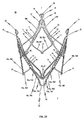
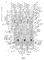
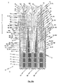
図4は、本発明の第4実施形態に係るステント10の平面展開図であり、本発明の第4実施形態に係るステント10の製造に適した切断パターンの二次元投影図に対応する。   FIG. 4 is a plan development view of the stent 10 according to the fourth embodiment of the present invention, and corresponds to a two-dimensional projection view of a cutting pattern suitable for manufacturing the stent 10 according to the fourth embodiment of the present invention.

ステント10の第4実施形態は、第3実施形態と類似している。しかしながら、第4実施形態のステントは、弁プロテーゼを締結するために追加の締結穴12aが設けられている。具体的には、追加の締結穴12aは、第1接続ウェブ17の下端17pにある。追加の締結穴12aは、締結部11と接続部22の間の第1接続ウェブ17上の小穴として構成される。当然ながら、追加の締結穴12aを小穴として構成せずに、第1接続ウェブ内に直接形成することも想定される。追加の締結穴12aにより、弁プロテーゼの上側領域をステント10に対してさらにしっかりと固定することが可能になる。   The fourth embodiment of the stent 10 is similar to the third embodiment. However, the stent of the fourth embodiment is provided with an additional fastening hole 12a for fastening the valve prosthesis. Specifically, the additional fastening hole 12 a is at the lower end 17 p of the first connection web 17. The additional fastening hole 12 a is configured as a small hole on the first connection web 17 between the fastening part 11 and the connection part 22. Of course, it is also envisaged that the additional fastening holes 12a are formed directly in the first connecting web without being configured as small holes. The additional fastening hole 12a allows the upper region of the valve prosthesis to be more securely fixed to the stent 10.

追加の締結穴12aの大きさは、弁プロテーゼをステント10に締結するために使用される特定の糸またはワイヤの太さに適合させてもよい。追加の締結穴12aの断面形状も、弁プロテーゼを締結するために使用される糸またはワイヤの断面形状に適合させてもよい。弁プロテーゼを心臓弁ステントに固定するための複数の追加の締結穴12aが存在するために、心臓弁ステントに対する弁プロテーゼの締結位置を正確に定めることができる。   The size of the additional fastening holes 12a may be adapted to the particular thread or wire thickness used to fasten the valve prosthesis to the stent 10. The cross-sectional shape of the additional fastening hole 12a may also be adapted to the cross-sectional shape of the thread or wire used to fasten the valve prosthesis. Due to the presence of a plurality of additional fastening holes 12a for securing the valve prosthesis to the heart valve stent, the fastening position of the valve prosthesis relative to the heart valve stent can be accurately determined.

締結穴12aの代わりに、ステント10の同じ領域に一つ以上の切り欠きが設けられていてもよい。これらの切り欠きは締結穴12aと同じ機能を果たし、ステント100内での弁プロテーゼのさらなる固定に貢献する。   Instead of the fastening hole 12a, one or more notches may be provided in the same region of the stent 10. These notches serve the same function as the fastening holes 12a and contribute to further securing the valve prosthesis within the stent 100.

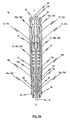
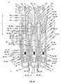
本発明の第5実施形態に係るステント10が、ステントの拡張された状態で図5a−図5cに示されている。図5aおよび図5bはステント10の側面図であり、図5cはステント10の上端3の平面図である。図5dは、本発明の第5実施形態に係るステントの平面展開図であり、本発明の第5実施形態に係るステントの製造に適した切断パターンの二次元投影図に対応する。ステントはチューブの一部、特に金属管から一体的に切り出される。   A stent 10 according to a fifth embodiment of the invention is shown in FIGS. 5a-5c with the stent expanded. FIGS. 5 a and 5 b are side views of the stent 10 and FIG. 5 c is a plan view of the upper end 3 of the stent 10. FIG. 5d is a plan development view of the stent according to the fifth embodiment of the present invention, and corresponds to a two-dimensional projection view of a cutting pattern suitable for manufacturing the stent according to the fifth embodiment of the present invention. The stent is integrally cut from a portion of the tube, particularly a metal tube.

第5実施形態に係るステント10は、第3実施形態のステントと構造および機能の点で類似する。特に、第5実施形態のステント10は、全部で三つの位置決めアーチ15a、15b、15cを同様に有しており、これらが肺動脈弁または大動脈弁の平面内でステント10を自動的に位置決めする機能を引き受ける。ステント10の他の実施形態のように、位置決めアーチ15a、15b、15cは丸いヘッド部20を有し、これが心臓の移植部位(図18a参照)におけるステント10の位置決めの間、治療される生体の心臓弁Hの嚢に係合する。   The stent 10 according to the fifth embodiment is similar in structure and function to the stent of the third embodiment. In particular, the stent 10 of the fifth embodiment similarly has a total of three positioning arches 15a, 15b, 15c that function to automatically position the stent 10 in the plane of the pulmonary or aortic valve. Undertake. As with other embodiments of the stent 10, the positioning arches 15a, 15b, 15c have a round head 20 which is the body of the body being treated during positioning of the stent 10 at the heart implantation site (see FIG. 18a). Engage with the sac of the heart valve H.

全部で三つの保持アーチ16a、16b、16cと三つの締結アーチ19a、19b、19cも設けられる。   A total of three holding arches 16a, 16b, 16c and three fastening arches 19a, 19b, 19c are also provided.

第5実施形態のステント10は、締結部11内に締結穴12に加えてさらに切り欠き26aが設けられている点で、第3実施形態のステントと相違する。図5dから分かるように、弁プロテーゼ100の組織部分の追加固定手段として、および縫合糸またはワイヤのガイドとして機能する一連の切り欠き26aが設けられる。これらの追加切り欠き26aは、体内プロテーゼ1が移植されるとき、縫合糸またはワイヤの移動を最小化し、第1接続ウェブ17とのこすれによる糸またはワイヤの摩耗を低減する。追加切り欠き26aによって弁プロテーゼの上側領域を心臓弁ステント10にしっかりと締結することができ、プロテーゼの移動を最小限とし、これによって縫合糸またはワイヤの摩擦により生じる摩耗の可能性がさらに最小化される。   The stent 10 of the fifth embodiment is different from the stent of the third embodiment in that a notch 26 a is further provided in the fastening portion 11 in addition to the fastening hole 12. As can be seen from FIG. 5d, a series of notches 26a are provided that serve as additional means of securing the tissue portion of the valve prosthesis 100 and as a guide for the suture or wire. These additional cutouts 26a minimize the movement of the suture or wire when the endoprosthesis 1 is implanted and reduce the wear of the yarn or wire due to rubbing with the first connecting web 17. An additional notch 26a allows the upper region of the valve prosthesis to be securely fastened to the heart valve stent 10, minimizing prosthesis movement, thereby further minimizing the possibility of wear caused by suture or wire friction. Is done.

当然ながら、追加ノッチ26aを縫合糸またはワイヤの太さに適合させることも考えられる。とりわけ、縫合糸またはワイヤの損傷を最小化するように追加ノッチ26aの半径を定めてもよい。   Of course, it is also conceivable to adapt the additional notch 26a to the thickness of the suture or wire. In particular, the radius of the additional notch 26a may be defined to minimize suture or wire damage.

ステント10の第5実施形態は、位置決めアーチ15a、15b、15cからステント10の上端3に向けて延びる放射アーチ32a、32b、32cを備える。図5aおよび図5bに最も明瞭に示されているように、ステント10は三つの放射アーチ32a、32b、32cを有し、各アーチ32a、32b、32cは、各位置決めアーチ15a、15b、15cの二つのアーム15a’、15a”、15b’、15b”、15c’、15c”の間に位置している。各放射アーチ32a、32b、32cは、各位置決めアーチ15a、15b、15cとはおおよそ逆の形状を有しており、位置決めアーチ15a、15b、15cのそれぞれ一つと反対の方向に延出する。   The fifth embodiment of the stent 10 includes radial arches 32 a, 32 b, 32 c that extend from the positioning arches 15 a, 15 b, 15 c toward the upper end 3 of the stent 10. As most clearly shown in FIGS. 5a and 5b, the stent 10 has three radial arches 32a, 32b, 32c, each arch 32a, 32b, 32c of each positioning arch 15a, 15b, 15c. Located between the two arms 15a ', 15a ", 15b', 15b", 15c ', 15c ". Each radial arch 32a, 32b, 32c is approximately the opposite of each positioning arch 15a, 15b, 15c. Each of the positioning arches 15a, 15b, 15c extends in the opposite direction.

図5dに示す切断パターンから特によく分かるように、放射アーチ32の各アーム32’、32”は、ステント10の全長の略中点で、反対側の位置決めアーチ15a、15b、15cのアーム15a’、15a”、15b’、15b”、15c’、15c”と融合する。   As can be seen particularly well from the cutting pattern shown in FIG. , 15a ″, 15b ′, 15b ″, 15c ′, 15c ″.

各放射アーチ32a、32b、32cの二つのアーム32’、32”は、丸い接続部またはヘッド部33によってステント10の上端3で互いに接続される。このヘッド部33は丸いだけでなく、ステント10が拡張され移植される状態にあるとき、血管の内壁に対して可能な限り大きな接触面積で接触するように先端が広がっている。   The two arms 32 ′, 32 ″ of each radial arch 32a, 32b, 32c are connected to each other at the upper end 3 of the stent 10 by a round connection or head 33. This head 33 is not only round, but also the stent 10 When the is in an expanded and implanted state, the tip expands to contact the inner wall of the blood vessel with as much contact area as possible.

各放射アーチ32a、32b、32cのヘッド部33は、移植前および移植中にステント10をカテーテル内に保持し、および/または移植後にステントを取り戻すことのできる追加手段としても機能する。   The head portion 33 of each radial arch 32a, 32b, 32c also serves as an additional means by which the stent 10 can be retained in the catheter before and / or during implantation and / or the stent can be retrieved after implantation.

図5cは、ステント10の上端3からみた斜視平面図であり、ステント10が拡張された状態にあるとき、ステント10の周囲外方に半径方向に延出するように放射アーチ32a、32b、32cがプログラムされている様子を示す。こうすると、ステント10の上端領域によって、血管壁に対して増大した接触力を与えることができる。したがって、その場所でステント10を固定するときの安全性が増加し、これによってステントが移動する可能性が低下する。したがって、拡張された状態では、位置決めアーチのクランプ効果に加えて、全てがステント10の周囲から半径方向外方に突出する保持アーチ16a、16b、16c、補助アーチ18a、18b、18cおよび放射アーチ32a、32b、32cによって及ぼされる半径方向の力によって、第5実施形態のステント10が適切な位置に固定される。   FIG. 5c is a perspective plan view from the upper end 3 of the stent 10, and when the stent 10 is in an expanded state, the radial arches 32a, 32b, 32c extend radially outwardly around the stent 10. FIG. Shows how is programmed. In this way, an increased contact force can be applied to the blood vessel wall by the upper end region of the stent 10. Therefore, the safety when fixing the stent 10 in place increases, thereby reducing the possibility of the stent moving. Thus, in the expanded state, in addition to the clamping effect of the positioning arches, the retaining arches 16a, 16b, 16c, the auxiliary arches 18a, 18b, 18c and the radial arches 32a all project radially outward from the periphery of the stent 10. , 32b, 32c, the radial force exerted on the stent 10 of the fifth embodiment is fixed in place.

カテーテル保持手段23または締結小穴24を有する締結手段が位置する平面を越えて、放射アーチ32a、32b、32cがステント10の長手方向Lに突出しないことが、図5dに示す切断パターンから分かる。これは、放射アーチ32a、32b、32cのヘッド部33と干渉することなく、カテーテル保持手段23が適切な移植カテーテル内の対応手段と協働できるようにしている。実際、上述したように、ヘッド部33自体をステント10の外植を遂行するための追加のカテーテル保持手段または追加手段として使用することができる。   It can be seen from the cutting pattern shown in FIG. 5d that the radial arches 32a, 32b, 32c do not protrude in the longitudinal direction L of the stent 10 beyond the plane in which the catheter holding means 23 or the fastening means having the fastening eyelets 24 are located. This allows the catheter holding means 23 to cooperate with corresponding means in a suitable implantation catheter without interfering with the head 33 of the radial arches 32a, 32b, 32c. Indeed, as described above, the head portion 33 itself can be used as an additional catheter holding or additional means for performing explantation of the stent 10.

原理上、半径方向の接触力をさらに増大するために、ステント10は三つより多い数の放射アーチ32を備えてもよい。例えば、移植部位においてステント10をさらに良好に固定可能とするために、放射アーチ32a、32b、32cの一部または全てに鉤状(barb)要素を設けることも可能である。   In principle, the stent 10 may include more than three radial arches 32 to further increase the radial contact force. For example, some or all of the radial arches 32a, 32b, 32c may be provided with barb elements to enable better fixation of the stent 10 at the implantation site.

本発明の第6実施形態に係るステント10を図6a−6dおよび図6f−6iに示す。図6a−6cは、拡張された状態にあるステント10の様々な側面斜視図である。一方、第6実施形態に係るステントの平面展開図を図6dに示す。この平面展開図は、第6実施形態に係るステントの製造に適した切断パターンの二次元投影図に対応する。   A stent 10 according to a sixth embodiment of the present invention is shown in FIGS. 6a-6d and 6f-6i. 6a-6c are various side perspective views of the stent 10 in an expanded state. On the other hand, a plan development view of the stent according to the sixth embodiment is shown in FIG. This plan development view corresponds to a two-dimensional projection view of a cutting pattern suitable for manufacturing the stent according to the sixth embodiment.

図6eは、心臓弁狭窄または心臓弁不全症を治療するための体内プロテーゼの側面斜視図であり、体内プロテーゼは、本発明の第6実施形態と同様の、弁プロテーゼを保持するための心臓弁ステントを備える。詳細には、図6eは、弁プロテーゼ100をステント10に固定する方法の一例として、ステント10に取り付けられた弁プロテーゼ100を示す。この例は、本明細書で述べるステント実施形態に適用可能である。   FIG. 6e is a side perspective view of an endoprosthesis for treating heart valve stenosis or heart valve insufficiency, the endoprosthesis being similar to the sixth embodiment of the present invention for holding a valve prosthesis With a stent. Specifically, FIG. 6 e shows the valve prosthesis 100 attached to the stent 10 as an example of a method for securing the valve prosthesis 100 to the stent 10. This example is applicable to the stent embodiments described herein.

図6fは、心臓弁狭窄または心臓弁不全症を治療するための体内プロテーゼの側面斜視図であり、体内プロテーゼは、本発明の第6実施形態に係る、弁プロテーゼを保持するための心臓弁ステントを備える。   FIG. 6f is a side perspective view of an endoprosthesis for treating heart valve stenosis or heart valve insufficiency, the endoprosthesis according to the sixth embodiment of the present invention for holding a valve prosthesis. Is provided.

図6gおよび図6hは、図6fに示した体内プロテーゼの様々な側面詳細図である。図6iは、図6fに示した体内プロテーゼの下端部の平面図である。   6g and 6h are various side detail views of the endoprosthesis shown in FIG. 6f. 6i is a plan view of the lower end of the endoprosthesis shown in FIG. 6f.

上述した実施形態にあるように、第6実施形態のステント10は、チューブの一部、特に金属管から切断された一体構造として構成される。切断パターンは、図6に二次元投影図として示されている。   As in the above-described embodiment, the stent 10 of the sixth embodiment is configured as an integral structure cut from a part of a tube, particularly a metal tube. The cutting pattern is shown as a two-dimensional projection in FIG.

ステント10の第6実施形態は、原理上、第5実施形態と構造および機能の点で類似している。繰り返しを避けるために、第5実施形態の上記説明を参照する。特に、ステント10の上側領域における半径方向に作用する接触力を増大させるために、本質的にU字形またはV字形の放射アーチ32a、32b、32cが同様に設けられる。   The sixth embodiment of the stent 10 is in principle similar in structure and function to the fifth embodiment. To avoid repetition, reference is made to the above description of the fifth embodiment. In particular, essentially U-shaped or V-shaped radial arches 32a, 32b, 32c are likewise provided to increase the radially acting contact force in the upper region of the stent 10.

弁プロテーゼの組織部分をさらに締結するために、追加締結部11aを備えた固定ブリッジ27が設けられている点で、第6実施形態は第5実施形態と相違する。心膜などの生体材料のシートから構築された弁が弁プロテーゼとして使用されるとき、すなわち、弁プロテーゼが数片の材料で構成されるとき、追加締結部11aを備えた固定ブリッジ27の存在は特に有利となる。心膜弁が使用されるとき、心膜材料がステント10にしっかりと取り付けられることを保証するために注意を払わなければならない。この理由のため、第6実施形態に係るステント10は、それぞれが追加締結部11aを備える全部で三つの固定ブリッジ27を有する。各固定ブリッジ27は第1接続ウェブ17の一つに取り付けられ、ステント10の下端2の方向に延出する。   The sixth embodiment differs from the fifth embodiment in that a fixing bridge 27 having an additional fastening portion 11a is provided to further fasten the tissue portion of the valve prosthesis. When a valve constructed from a sheet of biomaterial such as pericardium is used as a valve prosthesis, i.e. when the valve prosthesis is composed of several pieces of material, the presence of a fixed bridge 27 with an additional fastening part 11a is This is particularly advantageous. When a pericardial valve is used, care must be taken to ensure that the pericardial material is securely attached to the stent 10. For this reason, the stent 10 according to the sixth embodiment has a total of three fixed bridges 27 each provided with an additional fastening part 11a. Each fixed bridge 27 is attached to one of the first connecting webs 17 and extends in the direction of the lower end 2 of the stent 10.

固定ブリッジ27に設けられた追加締結部11aは、心膜材料または弁プロテーゼをステント10に締結するために使用される糸または細いワイヤを固定するための締結穴12bおよび/または他の締結手段、例えば切り欠き26bをさらに有しており、これによって弁プロテーゼの移動を最小限に、好ましくはゼロにすることができる。当然ながら、その直径が弁プロテーゼを締結するために使用される糸またはワイヤの太さに適合された締結穴または締結小穴を設けることも想定される。一般に、締結穴12bまたは切り欠き26bの半径は、摩擦により生ずる糸またはワイヤの摩耗をできるだけ最小とするように設定されるべきである。   An additional fastening portion 11a provided in the securing bridge 27 includes fastening holes 12b and / or other fastening means for securing a thread or thin wire used to fasten pericardial material or valve prosthesis to the stent 10. For example, it further includes a notch 26b, which allows the movement of the valve prosthesis to be minimized, preferably zero. Of course, it is also envisaged to provide fastening holes or fastening holes whose diameter is adapted to the thickness of the thread or wire used to fasten the valve prosthesis. In general, the radius of the fastening hole 12b or notch 26b should be set to minimize the wear of the yarn or wire caused by friction as much as possible.

心臓弁狭窄または心臓弁不全症を治療するための体内プロテーゼ1の側面図を表す図6eおよび図6fを参照する。図6fに示した実施形態では、ステント10は、弁プロテーゼ100を保持するための、本発明の第6実施形態にしたがうステントに対応する。第6実施形態に関して弁プロテーゼ100をステント10に固定する方法の説明は、本明細書に記載の他の実施形態に係るステント10にも適用可能である。   Reference is made to FIGS. 6e and 6f, which represent side views of an endoprosthesis 1 for treating heart valve stenosis or heart valve insufficiency. In the embodiment shown in FIG. 6 f, the stent 10 corresponds to a stent according to a sixth embodiment of the invention for holding the valve prosthesis 100. The description of the method of securing the valve prosthesis 100 to the stent 10 with respect to the sixth embodiment is also applicable to stents 10 according to other embodiments described herein.

弁プロテーゼ100は、生体材料または合成材料で作られた少なくとも一つの弁尖102(図6i参照)を備える。特に、図6eは体内プロテーゼ1の側面斜視図を表し、心臓弁ステント10が部分的に拡張された状態で示されている。図6fは体内プロテーゼ1の側面斜視図を表し、心臓弁ステント10が完全に拡張された状態で示されている。図6g−iは、図6fに示した体内プロテーゼ1の様々な詳細斜視図である。詳細には、図6gは保持アーチ16aのヘッド部30の詳細斜視図であり、図6hは追加締結部11aの詳細斜視図である。図6iは図6fに示した体内プロテーゼ1の下端部2の平面図である。   The valve prosthesis 100 comprises at least one leaflet 102 (see FIG. 6i) made of biomaterial or synthetic material. In particular, FIG. 6e represents a side perspective view of the endoprosthesis 1 with the heart valve stent 10 shown in a partially expanded state. FIG. 6f represents a side perspective view of the endoprosthesis 1 with the heart valve stent 10 fully expanded. 6g-i are various detailed perspective views of the endoprosthesis 1 shown in FIG. 6f. Specifically, FIG. 6g is a detailed perspective view of the head portion 30 of the holding arch 16a, and FIG. 6h is a detailed perspective view of the additional fastening portion 11a. 6i is a plan view of the lower end 2 of the endoprosthesis 1 shown in FIG. 6f.

ステント10が展開された心臓および血管の蠕動運動の間でさえも、ステント10に固定された弁プロテーゼ100のステント10に対する長手方向の変位が最小になるように、本発明の第6実施形態に係るステント10は、ステント10の長手方向Lに延びる複数の締結部11を備える。加えて、第6実施形態に係るステント100には、それぞれが第1接続ウェブ17の一つに取り付けられステント10の下端2の方向に延出する追加締結部11aが設けられる。締結部11および追加締結部11aの両方によって、弁プロテーゼ100の組織部分がステント10に固定される。   In a sixth embodiment of the present invention, the longitudinal displacement of the valve prosthesis 100 secured to the stent 10 relative to the stent 10 is minimized even during peristaltic movement of the heart and blood vessels in which the stent 10 is deployed. The stent 10 includes a plurality of fastening portions 11 extending in the longitudinal direction L of the stent 10. In addition, the stent 100 according to the sixth embodiment is provided with an additional fastening portion 11 a that is attached to one of the first connection webs 17 and extends in the direction of the lower end 2 of the stent 10. The tissue portion of the valve prosthesis 100 is fixed to the stent 10 by both the fastening portion 11 and the additional fastening portion 11a.

詳細には、弁プロテーゼ100の組織部分は、締結部11および追加締結部11aの締結穴12、12bをそれぞれ通して導かれる糸101または細いワイヤによって、ステント10に締結される。これにより、ステント10に対して予め定義された正確な位置に、弁プロテーゼ100をステント10に固定することが可能になる。弁プロテーゼ100をステント10に固定するための複数の締結穴12を設けることによって、ステント10上での弁プロテーゼ100の正確な位置決めが実現される。   Specifically, the tissue portion of the valve prosthesis 100 is fastened to the stent 10 by a thread 101 or thin wire guided through the fastening holes 11 and 12b of the fastening part 11 and the additional fastening part 11a, respectively. This allows the valve prosthesis 100 to be secured to the stent 10 at a precise position predefined with respect to the stent 10. By providing a plurality of fastening holes 12 for securing the valve prosthesis 100 to the stent 10, accurate positioning of the valve prosthesis 100 on the stent 10 is achieved.

本発明の第6実施形態に係るステントの変形例であるステント10を備えた体内プロテーゼ1を示す図6eを参照する。図6eに示したステント10は、まだ完全には拡張されていない。本発明の第6実施形態に係るステント10が完全に拡張された体内プロテーゼ1は、図6fに示されている。   Reference is made to FIG. 6e showing an endoprosthesis 1 comprising a stent 10 which is a variation of the stent according to the sixth embodiment of the present invention. The stent 10 shown in FIG. 6e has not yet been fully expanded. An endoprosthesis 1 with a fully expanded stent 10 according to a sixth embodiment of the invention is shown in FIG. 6f.

図18a−cを参照して詳細に後述するように、本発明に係るステント10は、心尖から(すなわちトランスアピカル(transapical))、または大腿動脈および大動脈弓を通して(すなわちトランスフェモラル(transfemoral))心臓の移植部位に到達する挿入カテーテルシステムを介して、侵襲を最小限にして折り畳まれた状態で前進する。挿入手順の間、弁プロテーゼ100が固定されたステント10は、カテーテルシステムの先端K内に折り畳まれた状態で収容される(図18a参照)。心臓の移植部位に到達すると、弁プロテーゼ100が固定されたステント10は、カテーテルシステムの搬送部の近位側Kの部分を選択的に操作することによって順に解放される。   As will be described in detail below with reference to FIGS. 18a-c, the stent 10 according to the present invention may be either from the apex (ie transapical) or through the femoral artery and aortic arch (ie transfemoral). Advance in a folded state with minimal invasion through an insertion catheter system that reaches the heart implantation site. During the insertion procedure, the stent 10 with the valve prosthesis 100 secured is housed in a folded state within the tip K of the catheter system (see FIG. 18a). Upon reaching the heart implantation site, the stent 10 with the fixed valve prosthesis 100 is released in sequence by selectively manipulating the proximal K portion of the catheter system delivery.

図18a−cに示す挿入手順は、大腿動脈および大動脈弓を通して(すなわち経大腿)心臓の移植部位に体内プロテーゼ1が挿入される挿入手順であることに注意するのが重要である。しかしながら、本発明は図18a−cを参照して説明される特定の搬送アクセスに限定されない。むしろ、体内プロテーゼ1の移植のために様々なアプローチを使用することができる。例えば、心尖から移植部位に体内プロテーゼを運ぶ、大動脈弁を治療するためのトランスアピカルアプローチなどである。   It is important to note that the insertion procedure shown in FIGS. 18a-c is an insertion procedure in which the endoprosthesis 1 is inserted through the femoral artery and the aortic arch (ie transfemoral) at the heart implantation site. However, the present invention is not limited to the specific transport access described with reference to FIGS. 18a-c. Rather, various approaches can be used for implantation of the endoprosthesis 1. For example, a transapical approach for treating an aortic valve that carries an internal prosthesis from the apex to the implantation site.

詳細には、第1解放ステップの間、ステント10の残りの部分、特に保持アーチ16a、16b、16c、補助アーチ18a−cおよび放射アーチ32a−cが依然として折り畳まれた状態(図18a参照)である一方、ステント10の位置決めアーチ15a−cが解放されるように、挿入カテーテルシステムの搬送部の近位側Kが操作される。第1解放ステップ中に解放される位置決めアーチ15a−cは、半径方向外方に拡張し展開する。その後、カテーテルシステムの搬送部の近位側Kを適切に移動することによって、拡張された位置決めアーチ15a−cを患者の生体心臓弁Hの嚢Tの中に挿入することができる(図18a参照)。   Specifically, during the first release step, the rest of the stent 10, in particular the retaining arches 16a, 16b, 16c, the auxiliary arches 18a-c and the radial arches 32a-c are still folded (see FIG. 18a). On the other hand, the proximal side K of the delivery portion of the insertion catheter system is manipulated so that the positioning arches 15a-c of the stent 10 are released. The positioning arches 15a-c released during the first release step expand and deploy radially outward. Thereafter, the expanded positioning arch 15a-c can be inserted into the sac T of the patient's living heart valve H by appropriately moving the proximal side K of the delivery portion of the catheter system (see FIG. 18a). ).

後に続く第2解放ステップでは、ステント10の下端部2を形成するアーチ(補助アーチ18a−cおよび保持アーチ16a、16b、16c)が解放される一方、ステント10の上端部3は依然として挿入カテーテルシステムの搬送部の近位側Kにしっかりと固定され、解放されることがないように、挿入カテーテルシステムの搬送部の近位側Kが操作される(図18a参照)。   In a subsequent second release step, the arches forming the lower end 2 of the stent 10 (auxiliary arches 18a-c and retaining arches 16a, 16b, 16c) are released while the upper end 3 of the stent 10 is still in the insertion catheter system. The proximal side K of the delivery part of the insertion catheter system is manipulated so that it is firmly fixed to the proximal side K of the delivery part of the insertion catheter and not released (see FIG. 18a).

ステント10に配置された位置決めアーチ15a−cおよび保持アーチ16a、16b、16cは、下側方向に、すなわちステント10の下端部2に向けて凸状および円弧状にカーブしていてもよく、このような丸みのある形状は、動脈の損傷を低減するとともに自己拡張中の展開を容易にすることができる。このような設計により、近隣の組織または血管を損傷することなく、生体心臓弁の嚢内に位置決めアーチ15a−cをより容易に挿入することが可能になる。   The positioning arches 15a-c and the holding arches 16a, 16b, 16c arranged on the stent 10 may be curved in a downward direction, that is, in a convex shape and an arc shape toward the lower end 2 of the stent 10, Such rounded shapes can reduce arterial damage and facilitate deployment during self-expansion. Such a design allows the positioning arches 15a-c to be more easily inserted into the sac of a living heart valve without damaging nearby tissue or blood vessels.

図6eには、弁プロテーゼ100が上記ステント10に固定された本発明の一実施形態に係るステント10を有する体内プロテーゼ1の第2解放ステップ後の状態が示されている。第2解放ステップでは、カテーテル保持手段23を備える上端部3のみが挿入カテーテルシステムの先端Kにしっかりと接続され、ステント10の残りの部分は既に解放され半径方向に拡張されている。図6eから、保持アーチ16a、16b、16cおよび補助アーチ18a−cの自己拡張のために、これらに固定された弁プロテーゼ100が既に(少なくとも部分的に)拡張されていることが分かる。   FIG. 6 e shows the state after the second release step of the endoprosthesis 1 having the stent 10 according to an embodiment of the present invention in which the valve prosthesis 100 is fixed to the stent 10. In the second release step, only the upper end 3 with the catheter holding means 23 is firmly connected to the tip K of the insertion catheter system, and the rest of the stent 10 has already been released and radially expanded. It can be seen from FIG. 6e that the valve prosthesis 100 secured thereto has already been (at least partially) expanded due to the self-expansion of the holding arches 16a, 16b, 16c and the auxiliary arches 18a-c.

図6eに示すように、ステント10の上端3は依然として挿入カテーテルシステムの搬送部(図6eには明示されていない)内の袖状部P内に収容されている。機能の確認が可能になる程度まで弁プロテーゼ100の展開および位置決めが行われるまで、この状態が維持される。   As shown in FIG. 6e, the upper end 3 of the stent 10 is still housed in the sleeve P in the delivery section of the insertion catheter system (not explicitly shown in FIG. 6e). This state is maintained until the valve prosthesis 100 is deployed and positioned to the extent that the function can be confirmed.

機能テストによって弁プロテーゼ100が十分に機能することが分かると、カテーテル保持手段23を有するステント10の上端3が完全に解放される(図18c参照)ように、袖状部Pを遠位に引き戻すことができる。   When the functional test shows that the valve prosthesis 100 is fully functional, the sleeve P is pulled back so that the upper end 3 of the stent 10 with the catheter retaining means 23 is fully released (see FIG. 18c). be able to.

糸101を用いて弁プロテーゼ100をステント10に固定する方法が図6eからさらに理解される。二つの隣合う保持アーチ16a、16bの間に延びる固定ブリッジ27の締結穴12bに縫い付けられた心膜弁プロテーゼ100が図示の実施形態で用いられる。図6cおよび図6fを参照のこと。弁プロテーゼ100は、実質的に円形の断面を有する事実上の管状であってもよい。ステント10の下端2では、弁プロテーゼ100はビード(bead)105状になる。体内プロテーゼ1の平面図では環状であるこのビード105は、弁プロテーゼ100を自身の上に巻き上げて弁プロテーゼ100の下端部を裏返すことによって形成される。図6eに示すように、環状ビード105は糸101によって縁取り(overedge)されている。環状のビード105は異なる構造であってもよい。   The method of securing the valve prosthesis 100 to the stent 10 using the thread 101 is further understood from FIG. A pericardial valve prosthesis 100 sewn into a fastening hole 12b of a fixed bridge 27 extending between two adjacent holding arches 16a, 16b is used in the illustrated embodiment. See Figures 6c and 6f. The valve prosthesis 100 may be substantially tubular with a substantially circular cross section. At the lower end 2 of the stent 10, the valve prosthesis 100 is in the form of a bead 105. This bead 105, which is annular in the plan view of the endoprosthesis 1, is formed by rolling the valve prosthesis 100 over itself and turning the lower end of the valve prosthesis 100 upside down. As shown in FIG. 6 e, the annular bead 105 is overedge by the thread 101. The annular bead 105 may have a different structure.

弁プロテーゼ100の下端にある環状ビード105は、蠕動運動があった場合でも、弁プロテーゼ100の周辺領域を体内プロテーゼ1の移植部位における血管にしっかりと固定することができ、また血管壁をしっかりと封止することができる。   The annular bead 105 at the lower end of the valve prosthesis 100 can firmly fix the peripheral region of the valve prosthesis 100 to the blood vessel at the implantation site of the internal prosthesis 1 and can firmly fix the blood vessel wall. It can be sealed.

弁プロテーゼ100の下端の環状ビード105は、ステント10の下端部2で良好な接触とより一様な構造とを提供して、移植状態の体内プロテーゼ1を固定するのに必要な半径方向力をより均一に分布させる。この点において、体内プロテーゼ1の移植後に封止および漏れの防止を実現することができる。時間が経過すると、組織が成長して体内プロテーゼ1をさらに固定し、体内プロテーゼ1の移植された状態の血管に対する任意の移動または漏れを防止する。生体血管内に体内プロテーゼ1を移植するとき、環状ビード105の周辺領域と血管壁との間のあらゆる漏れは、体内プロテーゼ1と病変した生体弁輪との間の良好な接触と半径方向圧力とによって封止される。したがって、ビード形状の領域105は、特に心臓サイクルの充満期(心臓拡張期)の間、しっかりとした封止を提供する。   An annular bead 105 at the lower end of the valve prosthesis 100 provides good contact and a more uniform structure at the lower end 2 of the stent 10 to provide the radial force necessary to secure the implanted endoprosthesis 1. Distribute more uniformly. In this respect, sealing and leakage prevention can be achieved after implantation of the endoprosthesis 1. Over time, the tissue grows to further secure the endoprosthesis 1 and prevent any movement or leakage of the endoprosthesis 1 relative to the implanted blood vessel. When implanting the endoprosthesis 1 in a living vessel, any leakage between the peripheral region of the annular bead 105 and the vessel wall will cause good contact and radial pressure between the endoprosthesis 1 and the diseased living annulus. Is sealed. Thus, the bead-shaped region 105 provides a tight seal, especially during the full phase of the cardiac cycle (diastolic phase).

図6iは、例えば図6fに示された体内プロテーゼ1の下端2の平面図であり、図6fに示された体内プロテーゼの流入側から見た図である。ここでは、体内プロテーゼ1のステント10が完全に拡張された状態で示されている。   6i is a plan view of the lower end 2 of the endoprosthesis 1 shown in FIG. 6f, for example, as viewed from the inflow side of the endoprosthesis shown in FIG. 6f. Here, the stent 10 of the endoprosthesis 1 is shown in a fully expanded state.

図6iに示すように、弁プロテーゼ100の弁尖102は、心臓の拡張期の開始時と同様に、半分閉鎖された位置にある。   As shown in FIG. 6i, the leaflets 102 of the valve prosthesis 100 are in a half-closed position, similar to the beginning of the diastole of the heart.

図6fおよび図6gに詳細に示されているように、追加締結部11aを備える固定ブリッジ27は、弁膜材料または弁プロテーゼ100の組織部分をステント10に締結するために用いられる糸または細いワイヤを固定するための切り欠き26bを有しており、弁プロテーゼの移動を最小限に、好ましくはゼロにすることができる。さらに、弁プロテーゼ100をステント10に固定するための締結手段として、補助アーチ18a−cが使用される。   As shown in detail in FIGS. 6f and 6g, the fixation bridge 27 with the additional fastening portion 11a is a thread or thin wire used to fasten the leaflet material or tissue portion of the valve prosthesis 100 to the stent 10. It has a notch 26b for locking so that the movement of the valve prosthesis can be minimized, preferably zero. In addition, auxiliary arches 18 a-c are used as fastening means for securing valve prosthesis 100 to stent 10.

図6fおよび図6gから、締結アーチ19a−cのそれぞれのヘッド部30’と補助アーチ18a−cのそれぞれのヘッド部31とがその中で係合する円周フラップを形成するように、弁プロテーゼ100の下側が裏返されていることが分かる。体内プロテーゼ1が移植されるとき、心臓の蠕動運動に起因するステント10と弁プロテーゼ100の間の相対運動が効果的に防止されるように、弁プロテーゼ100は遊びが最小限となるようにステント10に締結される。   From FIG. 6f and FIG. 6g, the valve prosthesis is such that each head portion 30 'of the fastening arch 19a-c and each head portion 31 of the auxiliary arch 18a-c form a circumferential flap that engages therein. It can be seen that the underside of 100 is turned over. When the endoprosthesis 1 is implanted, the valve prosthesis 100 is stented to minimize play so that relative movement between the stent 10 and the valve prosthesis 100 due to the peristaltic movement of the heart is effectively prevented. 10 is fastened.

本発明のステント10の第7実施形態を、図7a−cを参照して以下に説明する。ここで、図7bおよび図7cはそれぞれ、第7実施形態に係る完全に拡張されたステント10の斜視図である。   A seventh embodiment of the stent 10 of the present invention is described below with reference to FIGS. 7a-c. Here, FIGS. 7b and 7c are perspective views of the fully expanded stent 10 according to the seventh embodiment, respectively.

下端部を除き、第7実施形態に係るステント10は、図6a−dおよび図6f−iを参照して上述した本発明の第6実施形態に係るステントに本質的に対応している。   Except for the lower end, the stent 10 according to the seventh embodiment essentially corresponds to the stent according to the sixth embodiment of the present invention described above with reference to FIGS. 6a-d and 6f-i.

したがって、第7実施形態に係るステント10は全部で三つの位置決めアーチ15a、15b、15cを有しており、これらは肺動脈弁または大動脈弁の弁平面内でのステント10の自動位置決め機能を引き受ける。ステント10の他の実施形態のように、位置決めアーチ15a、15b、15cは、心臓の移植部位におけるステント10の位置決め中に(図18a参照)、治療される生体心臓弁Hの嚢に係合する丸いヘッド部20を有する。   Thus, the stent 10 according to the seventh embodiment has a total of three positioning arches 15a, 15b, 15c, which take over the automatic positioning function of the stent 10 in the valve plane of the pulmonary or aortic valve. As with other embodiments of stent 10, positioning arches 15a, 15b, 15c engage the sac of living heart valve H to be treated during positioning of stent 10 at the heart implantation site (see FIG. 18a). It has a round head portion 20.

全部で三つの保持アーチ16a、16b、16cも設けられる。しかしながら、第6実施形態のステント設計とは異なり、第17実施形態に係るステント設計では、各保持アーチ16a、16b、16cの二つのアーム16a’、16a”、16b’、16b”、16c’、16c”は、ほぼO字形構成を有する接続部を介して互いに接続されない。むしろ、第7実施形態では、保持アーチ16a、16b、16cの各アームの下端部が環状カラー40に融合するが、これについては以下でさらに詳細に説明する。   A total of three holding arches 16a, 16b, 16c are also provided. However, unlike the stent design of the sixth embodiment, in the stent design according to the seventeenth embodiment, the two arms 16a ′, 16a ″, 16b ′, 16b ″, 16c ′ of each holding arch 16a, 16b, 16c, 16c "are not connected to each other via a connection having a substantially O-shaped configuration. Rather, in the seventh embodiment, the lower ends of the arms of the holding arches 16a, 16b, 16c are fused to the annular collar 40, Will be described in more detail below.

本発明の第6実施形態におけるように、第7実施形態に係るステント設計には追加締結部11aを備える固定ブリッジ27が設けられ、弁プロテーゼの組織部分または弁プロテーゼの一部をさらに締結する。各固定ブリッジ27は第1接続ウェブ17の一つに取り付けられ、ステント10の下端2の方向に延出する。固定ブリッジ27に設けられた追加締結部11aは、弁膜材料または弁プロテーゼの組織部分をステント10に締結するために使用される糸または細いワイヤを固定する締結穴12bおよび切り欠き26bをさらに有し、弁プロテーゼの移動を最小限に、好ましくは移動しないようにすることができる。当然ながら、弁プロテーゼの組織部分を締結するために使用される糸またはワイヤの太さにその直径が適合された締結穴または締結小穴を設けることも想定される。   As in the sixth embodiment of the present invention, the stent design according to the seventh embodiment is provided with a fixed bridge 27 with an additional fastening portion 11a to further fasten the tissue portion of the valve prosthesis or a portion of the valve prosthesis. Each fixed bridge 27 is attached to one of the first connecting webs 17 and extends in the direction of the lower end 2 of the stent 10. The additional fastening portion 11a provided in the securing bridge 27 further has a fastening hole 12b and a notch 26b for securing a thread or thin wire used for fastening the tissue portion of the valve membrane material or the valve prosthesis to the stent 10. The movement of the valve prosthesis can be minimized, preferably not moved. Of course, it is also envisaged to provide a fastening hole or a fastening hole whose diameter is adapted to the thickness of the thread or wire used for fastening the tissue part of the valve prosthesis.

ステント10の第7実施形態は、位置決めアーチ15a、15b、15cからステント10の上端3に向けて延出する放射アーチ32a、32b、32cも備える。図7bおよび図7cに最も明瞭に示されているように、ステント10は、各位置決めアーチ15a、15b、15cの二つのアーム15a’、15a”、15b’、15b”、15c’、15c”の間に各アーチ32a、32b、32cが配置された、三つの放射アーチ32a、32b、32cを有する。各放射アーチ32a、32b、32cは、各位置決めアーチ15a、15b、15cとはおおよそ反対の形状を有し、位置決めアーチ15a、15b、15cのそれぞれ一つと反対方向に延びる。   The seventh embodiment of the stent 10 also includes radial arches 32a, 32b, 32c extending from the positioning arches 15a, 15b, 15c toward the upper end 3 of the stent 10. As most clearly shown in FIGS. 7b and 7c, the stent 10 includes two arms 15a ′, 15a ″, 15b ′, 15b ″, 15c ′, 15c ″ of each positioning arch 15a, 15b, 15c. It has three radial arches 32a, 32b, 32c with each arch 32a, 32b, 32c disposed in between, each radial arch 32a, 32b, 32c being roughly opposite in shape to each positioning arch 15a, 15b, 15c. Extending in the opposite direction to each of the positioning arches 15a, 15b, 15c.

体内プロテーゼ1の移植された状態では、心臓サイクルの充満期(心臓拡張期)の間にかなりの力が弁プロテーゼ100に作用し、この力は弁プロテーゼ100に固定されたステントに伝達されるので、弁プロテーゼ100の固定されたステント10を移植部位にしっかりと固定することが重要なのは明らかである。以下で述べるステント10の第7−第11実施形態は、保持アーチ、補助アーチおよび放射アーチの上述の実施形態に追加して提供可能であり、移植部位においてステント10、体内プロテーゼ1をそれぞれさらにしっかりと固定することができ、また体内プロテーゼ1の位置変位を防止することができる、さらなる手段を含む。   In the implanted state of the endoprosthesis 1, a significant force acts on the valve prosthesis 100 during the full phase of the cardiac cycle (diastolic phase) and this force is transmitted to the stent secured to the valve prosthesis 100. Clearly, it is important to secure the stent 10 with the valve prosthesis 100 secured to the implantation site. Seventh to eleventh embodiments of the stent 10 described below can be provided in addition to the above-described embodiments of the retention arch, auxiliary arch and radial arch, which further secure the stent 10 and the endoprosthesis 1 respectively at the implantation site. And further means that can prevent positional displacement of the endoprosthesis 1.

詳細には、図7b−cに示すステント10の追加固定手段として、ステント10の下端部2を形成する少なくとも一つの環状カラー(襟状部)40が第7実施形態にしたがって提供される。   Specifically, at least one annular collar (collar) 40 forming the lower end 2 of the stent 10 is provided according to the seventh embodiment as an additional securing means for the stent 10 shown in FIGS. 7b-c.

図7aは、本発明の第7実施形態に係る別の心臓弁ステントの平面展開図である。図7aの平面展開図は、第7実施形態にしたがった心臓弁ステントをチューブの一部、特に金属管から一体的に切り出して第7実施形態に係る心臓弁ステントを製造するのに使用可能である切断パターンの二次元投影図に対応する。   FIG. 7a is a developed plan view of another heart valve stent according to the seventh embodiment of the present invention. 7a can be used to manufacture a heart valve stent according to the seventh embodiment by integrally cutting a heart valve stent according to the seventh embodiment from a part of a tube, particularly a metal tube. It corresponds to a two-dimensional projection view of a certain cutting pattern.

環状カラー40のステント本体への接続とは別に、図7aに示すステント設計は、図7b−cに示すステント10の設計に対応する。詳細には、図7aの展開図に示すステント設計によると、第7実施形態の修正では、締結アーチ19a、19b、19cと保持アーチ16a、16b、16cとがステントに設けられる。図7aの展開図に示すように、一つの結アーチ19a、19b、19cと一つの保持アーチ16a、16b、16cとが各位置決めアーチ15a、15b、15cに割り当てられる。各保持アーチ16a、16b、16cは、補助アーチ18a、18b、18cによって隣合う保持アーチと接続される。保持アーチ16a、16b、16cの各アーム16a’、16a”、16b’、16b”、16c’、16c”に、複数の締結穴12を持つ締結部が設けられる。   Apart from connecting the annular collar 40 to the stent body, the stent design shown in FIG. 7a corresponds to the design of the stent 10 shown in FIGS. 7b-c. Specifically, according to the stent design shown in the exploded view of FIG. 7a, in the modification of the seventh embodiment, fastening arches 19a, 19b, 19c and retaining arches 16a, 16b, 16c are provided on the stent. As shown in the developed view of FIG. 7a, one connection arch 19a, 19b, 19c and one holding arch 16a, 16b, 16c are assigned to each positioning arch 15a, 15b, 15c. Each holding arch 16a, 16b, 16c is connected to an adjacent holding arch by auxiliary arches 18a, 18b, 18c. Each arm 16a ', 16a ", 16b', 16b", 16c ', 16c "of the holding arch 16a, 16b, 16c is provided with a fastening portion having a plurality of fastening holes 12.

しかしながら、例えば第6実施形態のステント設計とは異なり、図7aのステント設計では、各保持アーチ16a、16b、16cの二つのアーム16a’、16a”、16b’、16b”、16c’、16c”と、各締結アーチ19a、19b、19cの二つのアーム19a’、19a”、19b’、19b”、19c’、19c”のいずれも、ほぼO字形構成を有する接続部を介して互いに接続されない。むしろ、図7aに示すステント設計では、保持アーチ16a、16b、16cの各アームの下端部と、締結アーチ19a、19b、19cの各アームの下端部とが、図7b−cに示すステント設計の環状カラーと同一の構成を有する環状カラー40に融合する。   However, unlike, for example, the stent design of the sixth embodiment, in the stent design of FIG. 7a, the two arms 16a ′, 16a ″, 16b ′, 16b ″, 16c ′, 16c ″ of each holding arch 16a, 16b, 16c. Neither of the two arms 19a ′, 19a ″, 19b ′, 19b ″, 19c ′, 19c ″ of each fastening arch 19a, 19b, 19c is connected to each other via a connection portion having a substantially O-shaped configuration. Rather, in the stent design shown in FIG. 7a, the lower end of each arm of the retaining arches 16a, 16b, 16c and the lower end of each arm of the fastening arches 19a, 19b, 19c are the same as in the stent design shown in FIGS. The annular collar 40 having the same configuration as the annular collar is fused.

図7aに示すステント設計とは異なり、図b−cに示すステント10には、保持アーチ16a、16b、16cの各保持アーム16a’、16a”、16b’、16b”、16c’、16c”の下端部のそれぞれまたは一部と単に接続される環状カラー40が設けられるが、この理由は、図7b−cに示すステント10には、図7aに示すステント設計のような締結アーチが設けられていないからである。しかしながら、図7aに示すステント設計には、保持アーチ16a、16b、16cの各保持アーム16a’、16a”、16b’、16b”、16c’、16c”の下端部のそれぞれまたは一部と接続されるとともに、締結アーチ19a−cの各アーム19a’、19a”、19b’、19b”、19c’、19c”の下端部のそれぞれまたは一部と接続される環状カラー40が設けられる。   Unlike the stent design shown in FIG. 7a, the stent 10 shown in FIGS. Bc includes the holding arms 16a ′, 16a ″, 16b ′, 16b ″, 16c ′, 16c ″ of the holding arches 16a, 16b, 16c. An annular collar 40 is provided that is simply connected to each or a portion of the lower end because the stent 10 shown in FIGS. 7b-c is provided with a fastening arch such as the stent design shown in FIG. 7a. However, the stent design shown in Fig. 7a includes a respective lower end of each holding arm 16a ', 16a ", 16b', 16b", 16c ', 16c "of the holding arch 16a, 16b, 16c or Each of the arms 19a ′, 19a ″, 19b ′, 19b ″, 19c ′, and 19c ″ of the fastening arch 19a-c is connected to a part of the arm 19a-c. Or annular collar 40 is provided to be connected to the part.

しかしながら、一般に、第7実施形態のステント10では、環状カラー40は、補助アーチ18a、18b、18cの各アーム18a’、18a”、18b’、18b”、18c’、18c”の下端部のそれぞれまたは一部と接続されてもよい。これは、図7aの平面展開図、図7bの側面図または図7cの斜視図から特に理解することができる。   However, in general, in the stent 10 of the seventh embodiment, the annular collar 40 is provided at the lower end of each arm 18a ′, 18a ″, 18b ′, 18b ″, 18c ′, 18c ″ of each of the auxiliary arches 18a, 18b, 18c. Alternatively, it may be connected to a part, which can be understood in particular from a plan development in FIG. 7a, a side view in FIG.

環状カラー40は、上記ステント10の非拡張状態時にステント10の長手軸と平行に走り、横方向ウェブ42(図7a参照)により相互接続される複数の支持ウェブ41を有する。ステント10の拡張状態時には、支持ウェブ41と横方向ウェブ42とが菱形状、または蛇紋状(serpentine)の環状カラー40を形成し、体内プロテーゼ1、ステント10それぞれの移植状態時に血管壁と接触する。図7bおよび図7cは、拡張状態にある環状カラー40を示す。   The annular collar 40 has a plurality of support webs 41 that run parallel to the longitudinal axis of the stent 10 when the stent 10 is unexpanded and are interconnected by transverse webs 42 (see FIG. 7a). When the stent 10 is in the expanded state, the support web 41 and the lateral web 42 form a diamond-shaped or serpentine-shaped collar 40 and come into contact with the blood vessel wall when the endoprosthesis 1 and the stent 10 are implanted. . Figures 7b and 7c show the annular collar 40 in an expanded state.

環状カラー40は、自己拡張により発現する半径方向の力を血管壁に伝達する経路となる支持体として機能する。ステント10の比較的広い接触面積が血管壁と相互作用するので、また環状カラー40の菱形状、または蛇紋状構造のために、半径方向の力が増大するにもかかわらず、動脈または組織に損傷を与える危険性を低減することができる。   The annular collar 40 functions as a support serving as a path for transmitting a radial force generated by self-expansion to the blood vessel wall. Due to the relatively large contact area of the stent 10 interacting with the vessel wall, and due to the diamond-shaped or serpentine structure of the annular collar 40, damage to the artery or tissue despite increased radial force Can reduce the risk of giving.

したがって、環状カラー40を設けることによって自己拡張後のステント10の剛性を高めるだけでなく、ステント10の移植部位での固定を改善すなわち強化することができる。加えて、環状カラー40の環状の断面形状は、血管壁と体内プロテーゼ1の間の封止も改善する。   Therefore, the provision of the annular collar 40 not only increases the rigidity of the stent 10 after self-expansion, but also improves or strengthens the fixation of the stent 10 at the implantation site. In addition, the annular cross-sectional shape of the annular collar 40 also improves the seal between the vessel wall and the endoprosthesis 1.

このような環状カラー40は、自己拡張可能な支持構造として有利に構成される。これは、半径方向外向きに作用する接触圧およびその設計のために、移植部位におけるステント10の固定がさらに改善されるという有利な効果を与え、その結果、弁プロテーゼ100を備えるステント10の変位または回転をさらに防止することができる。   Such an annular collar 40 is advantageously configured as a self-expandable support structure. This has the advantageous effect of further improving the fixation of the stent 10 at the implantation site due to the contact pressure acting radially outward and its design, so that the displacement of the stent 10 with the valve prosthesis 100 is improved. Or rotation can be further prevented.

本発明のステント10の第8実施形態を図8a−cに示す。詳細には、図8bおよび図8cはそれぞれ第8実施形態のステント10の斜視図であり、ステント10が完全に拡張されている。図8aは、本発明の第8実施形態に係る心臓弁ステントの平面展開図である。図8aの平面展開図は、第8実施形態にしたがった心臓弁ステントをチューブの一部、特に金属管から一体的に切り出す製造に適用可能である切断パターンの二次元投影図に対応する。   An eighth embodiment of the stent 10 of the present invention is shown in FIGS. 8a-c. Specifically, FIGS. 8b and 8c are perspective views of the stent 10 of the eighth embodiment, respectively, where the stent 10 is fully expanded. FIG. 8a is a developed plan view of a heart valve stent according to an eighth embodiment of the present invention. The plan development of FIG. 8a corresponds to a two-dimensional projection of a cutting pattern applicable to the production of a heart valve stent according to the eighth embodiment cut out of a part of the tube, in particular a metal tube.

上端部を除き、第8実施形態に係るステント10は、図5a−dを参照して上述した本発明の第5実施形態に係るステントと本質的に対応している。   Except for the upper end, the stent 10 according to the eighth embodiment essentially corresponds to the stent according to the fifth embodiment of the present invention described above with reference to FIGS. 5a-d.

したがって、第8実施形態のステント10は全部で三つの位置決めアーチ15a、15b、15cを有し、肺動脈弁または大動脈弁の弁平面内でのステント10の自動位置決め機能を引き受ける。ステント10の他の実施形態のように、位置決めアーチ15a、15b、15cは丸いヘッド部20を有し、ヘッド部は心臓の移植部位でのステントの位置決め中に、治療される生体心臓弁Hの嚢に係合する(図18a参照)。   Thus, the stent 10 of the eighth embodiment has a total of three positioning arches 15a, 15b, 15c and assumes the automatic positioning function of the stent 10 in the pulmonary or aortic valve plane. As in other embodiments of the stent 10, the positioning arches 15a, 15b, 15c have a round head portion 20, which is the head portion of the living heart valve H to be treated during stent positioning at the heart implantation site. Engage with the sac (see FIG. 18a).

全部で三つの保持アーチ16a、16b、16cおよび三つの締結アーチ19a、19b、19cも設けられる。   A total of three holding arches 16a, 16b, 16c and three fastening arches 19a, 19b, 19c are also provided.

さらに、第8実施形態のステント10には、締結部11内の締結穴12に加えて、弁プロテーゼ100の組織部分の追加固定手段および縫合糸またはワイヤのガイドとして機能する切り欠き26aが設けられる。これらの追加切り欠き26aは、縫合糸またはワイヤの移動を最小化し、これによって、体内プロテーゼ1が移植されるとき、第1接続ウェブ17上でのこすれによる糸またはワイヤの摩耗が低減される。追加切り欠き26aは、弁プロテーゼの上側領域が心臓弁ステント10にしっかりと締結されるようにし、プロテーゼの移動を最小限にし、これによって縫合糸またはワイヤの摩擦により生じる摩耗の可能性をさらに最小化する。   Furthermore, in addition to the fastening hole 12 in the fastening part 11, the stent 10 of the eighth embodiment is provided with a notch 26a that functions as an additional fixing means for the tissue portion of the valve prosthesis 100 and a suture or wire guide. . These additional cutouts 26a minimize the movement of the suture or wire, thereby reducing thread or wire wear due to rubbing on the first connecting web 17 when the endoprosthesis 1 is implanted. The additional notch 26a allows the upper region of the valve prosthesis to be securely fastened to the heart valve stent 10 to minimize prosthesis movement, thereby further minimizing the possibility of wear caused by suture or wire friction. Turn into.

全部で三つの保持アーチ16a、16b、16cおよび三つの締結アーチ19a、19b、19cも設けられる。   A total of three holding arches 16a, 16b, 16c and three fastening arches 19a, 19b, 19c are also provided.

しかしながら、第7実施形態(図7a−c参照)とは対照的に、ステント10の下端部2は第8実施形態で変更されないが、ステント10の上端部3には上部環状カラー40’が形成される。図8bおよび図8cに示すように、環状カラー40’は支持ウェブ41および横方向ウェブ42で構成され、拡張状態時に菱形の支持構造を形成する。   However, in contrast to the seventh embodiment (see FIGS. 7a-c), the lower end 2 of the stent 10 is not modified in the eighth embodiment, but the upper annular collar 40 ′ is formed at the upper end 3 of the stent 10. Is done. As shown in FIGS. 8b and 8c, the annular collar 40 'is composed of a support web 41 and a transverse web 42 to form a diamond-shaped support structure when in the expanded state.

図8aに係る切断パターンの図から、第8実施形態で利用される上部環状カラー40’は放射アーチ32a、32b、32cの上側ヘッド部と接続されることが分かる。他方、上部環状カラー40’は、拡張状態時(図8b、図8c参照)にカテーテル保持手段23が位置づけられる面から離して配置されるように第2接続ウェブ25と接続される。具体的には、第8実施形態の環状カラー40’は、カテーテル保持手段23が位置する平面と、隣合う位置決めアーチ15a−cの二つのアームの接続部22が位置する平面との間に置かれる。この目的のために、第5実施形態の接続ウェブと比較して、接続ウェブ25は幾分長くなるように構成される。   From the diagram of the cutting pattern according to FIG. 8a, it can be seen that the upper annular collar 40 'utilized in the eighth embodiment is connected to the upper head portions of the radial arches 32a, 32b, 32c. On the other hand, the upper annular collar 40 'is connected to the second connection web 25 so as to be arranged away from the surface on which the catheter holding means 23 is positioned in the expanded state (see FIGS. 8b and 8c). Specifically, the annular collar 40 ′ of the eighth embodiment is placed between the plane where the catheter holding means 23 is located and the plane where the connecting portions 22 of the two arms of the adjacent positioning arches 15 a-c are located. It is burned. For this purpose, the connecting web 25 is configured to be somewhat longer than the connecting web of the fifth embodiment.

第8実施形態で利用される上部環状カラー40’は、第7実施形態で利用される下部環状カラー40と機能の点で類似するので、明確さのためにこれ以上は説明しない。特に、上部環状カラー40’は、移植状態にある体内プロテーゼの移動を防止するように適切に固定し、また半径方向力を一様に分布させる。   The upper annular collar 40 'utilized in the eighth embodiment is similar in function to the lower annular collar 40 utilized in the seventh embodiment and will not be further described for clarity. In particular, the upper annular collar 40 'is properly secured to prevent movement of the endoprosthesis in the implanted state and distributes the radial force uniformly.

以下では、図9aおよび図9bを参照して本発明に係るステント10の第9実施形態を説明する。図9bは、第9実施形態に係るステント10の拡張された状態の斜視図である。図9aは、本発明の第9実施形態に係る心臓弁ステントの平面図である。図9aの平面図は、心臓弁ステントをチューブの一部から、特に金属管から一体的に切り出すために、本発明の第9実施形態に係る心臓弁ステントの製造に適用可能である切断パターンの二次元投影図に対応する。   Hereinafter, a ninth embodiment of the stent 10 according to the present invention will be described with reference to FIGS. 9a and 9b. FIG. 9 b is a perspective view of the expanded state of the stent 10 according to the ninth embodiment. FIG. 9a is a plan view of a heart valve stent according to a ninth embodiment of the present invention. The top view of FIG. 9a shows a cutting pattern applicable to the manufacture of a heart valve stent according to a ninth embodiment of the present invention in order to cut the heart valve stent from a part of the tube, in particular from a metal tube. Corresponds to 2D projection.

上部環状カラー40’はステント10の上端部3に同様に形成されるので、第9実施形態に係るステント10は、図8a−cに係る上述のステント(第8実施形態)と類似している。第8実施形態と比較して、第9実施形態の上部環状カラー40’は、ステント10の長手方向により長くなるように構成される。具体的には、図9bおよび図8bを比較すると、第9実施形態では、環状カラー40’として互いに頂上に位置する二つの菱形環状体が使用されていることが分かる。これは、ステント10が上端部3から及ぼす半径方向の接触力を増大させる。図9a−bに係る実施形態では、対応する細長い接続ウェブ25が利用される。   Since the upper annular collar 40 'is similarly formed on the upper end 3 of the stent 10, the stent 10 according to the ninth embodiment is similar to the above-described stent according to Figs. 8a-c (eighth embodiment). . Compared to the eighth embodiment, the upper annular collar 40 ′ of the ninth embodiment is configured to be longer in the longitudinal direction of the stent 10. Specifically, comparing FIG. 9b and FIG. 8b, it can be seen that in the ninth embodiment, two diamond-shaped annular bodies positioned on top of each other are used as the annular collar 40 '. This increases the radial contact force that the stent 10 exerts from the upper end 3. In the embodiment according to FIGS. 9a-b, a corresponding elongated connecting web 25 is utilized.

図10は、本発明の第10実施形態に係る心臓弁ステント10の平面展開図である。この平面図は、チューブの一部から、特に金属管から、本発明の第10実施形態に係る心臓弁ステント10を一体部品として切り出すために使用可能な切断パターンの二次元投影図である。   FIG. 10 is a plan development view of the heart valve stent 10 according to the tenth embodiment of the present invention. This plan view is a two-dimensional projection of a cutting pattern that can be used to cut out a heart valve stent 10 according to a tenth embodiment of the present invention from a part of a tube, in particular from a metal tube, as an integral part.

図8a−bを参照して上述した第8実施形態および図9a−bを参照して上述した第9実施形態と同じく、本発明のステント10の第10実施形態は、図5a−dを参照して上述した実施形態と本質的に対応している。   Similar to the eighth embodiment described above with reference to FIGS. 8a-b and the ninth embodiment described above with reference to FIGS. 9a-b, a tenth embodiment of the stent 10 of the present invention is described with reference to FIGS. 5a-d. This essentially corresponds to the embodiment described above.

しかしながら、例えば第8実施形態(図8a−c参照)とは対照的に、ステント10の上端部3は第10実施形態で変更されないが、ステント10の下端部2には下部環状カラー40が形成される。図10に示すように、環状カラー40は支持ウェブ41および横方向ウェブ42で構成され、拡張状態時に菱形の支持構造を形成する。   However, in contrast to, for example, the eighth embodiment (see FIGS. 8a-c), the upper end 3 of the stent 10 is not changed in the tenth embodiment, but the lower annular portion 40 is formed at the lower end 2 of the stent 10. Is done. As shown in FIG. 10, the annular collar 40 is composed of a support web 41 and a transverse web 42, and forms a diamond-shaped support structure in the expanded state.

図10に係る切断パターンの図から、第10実施形態で利用される下部環状カラー40は、保持アーチ16a、16b、16c、締結アーチ19a、19b、19cおよび補助アーチ18a、18b、18cの下側ヘッド部と接続されることが分かる。他方、下部環状カラー40は、拡張状態時にカテーテル保持手段23が位置づけられる面から離して配置されるように、保持アーチ16a、16b、16c、締結アーチ19a、19b、19cおよび補助アーチ18a、18b、18cと接続される。   From the diagram of the cutting pattern according to FIG. 10, the lower annular collar 40 used in the tenth embodiment is below the holding arches 16a, 16b, 16c, the fastening arches 19a, 19b, 19c and the auxiliary arches 18a, 18b, 18c. It can be seen that it is connected to the head part. On the other hand, the lower annular collar 40 is arranged away from the surface on which the catheter holding means 23 is positioned in the expanded state, the holding arches 16a, 16b, 16c, the fastening arches 19a, 19b, 19c and the auxiliary arches 18a, 18b, 18c.

第10実施形態で利用される下部環状カラー40は、第7実施形態で利用される下部環状カラー40と機能の点で類似するので、明確さのためにこれ以上は説明しない。   The lower annular collar 40 utilized in the tenth embodiment is similar in function to the lower annular collar 40 utilized in the seventh embodiment and will not be further described for clarity.

図11は、本発明の第11実施形態に係る心臓弁ステント10の平面展開図である。   FIG. 11 is a plan development view of the heart valve stent 10 according to the eleventh embodiment of the present invention.

上端部および下端部を除き、第11実施形態に係るステント10は、図5a−dを参照して上述した本発明の第5実施形態に係るステントと類似する。   Except for the upper and lower ends, the stent 10 according to the eleventh embodiment is similar to the stent according to the fifth embodiment of the present invention described above with reference to FIGS. 5a-d.

したがって、第11実施形態のステント10は全部で三つの位置決めアーチ15a、15b、15cを有し、肺動脈弁または大動脈弁の弁平面内でのステント10の自動位置決め機能を引き受ける。ステント10の他の実施形態のように、位置決めアーチ15a、15b、15cは丸いヘッド部20を有し、ヘッド部は心臓の移植部位でのステントの位置決め中に、治療される生体心臓弁Hの嚢に係合する(図18a参照)。   Accordingly, the stent 10 of the eleventh embodiment has a total of three positioning arches 15a, 15b, 15c and assumes the automatic positioning function of the stent 10 in the valve plane of the pulmonary or aortic valve. As in other embodiments of the stent 10, the positioning arches 15a, 15b, 15c have a round head portion 20, which is the head portion of the living heart valve H to be treated during stent positioning at the heart implantation site. Engage with the sac (see FIG. 18a).

全部で三つの保持アーチ16a、16b、16cおよび三つの締結アーチ19a、19b、19cも設けられる。   A total of three holding arches 16a, 16b, 16c and three fastening arches 19a, 19b, 19c are also provided.

ステント10の第11実施形態は、位置決めアーチ15a、15b、15cからステント10の上端3に向けて延出する放射アーチ32a、32b、32cも備える。図11に示すように、ステント10は、各位置決めアーチ15a、15b、15cの二つのアーム15a’、15a”、15b’、15b”、15c’、15c”の間に各アーチ32a、32b、32cが配置された、三つの放射アーチ32a、32b、32cを有する。各放射アーチ32a、32b、32cは、各位置決めアーチ15a、15b、15cとはおおよそ反対の形状を有し、位置決めアーチ15a、15b、15cのそれぞれ一つと反対方向に延びる。   The eleventh embodiment of the stent 10 also includes radial arches 32a, 32b, 32c extending from the positioning arches 15a, 15b, 15c toward the upper end 3 of the stent 10. As shown in FIG. 11, the stent 10 includes each arch 32a, 32b, 32c between two arms 15a ′, 15a ″, 15b ′, 15b ″, 15c ′, 15c ″ of each positioning arch 15a, 15b, 15c. The three radiating arches 32a, 32b, and 32c are disposed in the shape of each of the radiating arches 32a, 32b, and 32c. , 15c extend in the opposite direction.

ステント10の下端部2および上端部2’を形成する二つの環状カラー40、40’が第11実施形態にしたがってステント10の追加固定手段として設けられている点で、ステントの第11実施形態(図11参照)は図5a−dを参照して上述した本発明の第5実施形態とは異なる。図7a−cを参照して上述した第7実施形態のように、下部環状カラー40は、保持アーチ16a、16b、16cのそれぞれの保持アーム16a’、16a”、16b’、16b”、16c’、16c”の下端部、および締結アーチ19a−cのそれぞれのアーム19a’、19a”、19b’、19b”、19c’、19c”の下端部に接続されるが、このことは図11にしたがった切断パターンから特に理解することができる。他方、第11実施形態で利用される上部環状カラー40’は、放射アーチ32a、32b、32cの上側ヘッド部に接続される。詳細には、第11実施形態の環状カラー40’は、カテーテル保持手段23が位置する平面と、隣合う位置決めアーチ15a−cの二つのアームの接続部22が位置する平面の間に置かれる。   In the eleventh embodiment of the stent, two annular collars 40, 40 'forming the lower end 2 and the upper end 2' of the stent 10 are provided as additional fixing means for the stent 10 according to the eleventh embodiment. FIG. 11) differs from the fifth embodiment of the invention described above with reference to FIGS. 5a-d. As in the seventh embodiment described above with reference to FIGS. 7a-c, the lower annular collar 40 is provided with respective holding arms 16a ′, 16a ″, 16b ′, 16b ″, 16c ′ of the holding arches 16a, 16b, 16c. , 16c ″, and the lower ends of the respective arms 19a ′, 19a ″, 19b ′, 19b ″, 19c ′, 19c ″ of the fastening arch 19a-c, as shown in FIG. Can be particularly understood from the cutting pattern. On the other hand, the upper annular collar 40 'used in the eleventh embodiment is connected to the upper head portions of the radial arches 32a, 32b, 32c. Specifically, the annular collar 40 'according to the eleventh embodiment is placed between the plane where the catheter holding means 23 is located and the plane where the connecting portions 22 of the two arms of the adjacent positioning arches 15a-c are located.

本発明の第10実施形態に関して上述したように、上部環状カラーおよび下部環状カラー40、40’は、上記ステント10の非拡張状態時にステント10の長手軸と平行に走り、横方向ウェブ42(図11参照)によって相互接続される複数の支持ウェブ41を有する。ステント10の拡張状態時には、支持ウェブ41および横方向ウェブ42とが菱形状、または蛇紋状の環状カラー40、40’を形成し、体内プロテーゼ1、ステント10それぞれの移植状態時に血管壁と接触する。   As described above with respect to the tenth embodiment of the present invention, the upper and lower annular collars 40, 40 'run parallel to the longitudinal axis of the stent 10 when the stent 10 is in an unexpanded state, and the transverse web 42 (FIG. 11)). When the stent 10 is in the expanded state, the support web 41 and the lateral web 42 form a diamond-shaped or serpentine-shaped annular collar 40, 40 ', and come into contact with the blood vessel wall when the endoprosthesis 1 and the stent 10 are implanted. .

図8aおよび図9aに係る切断パターンを比較すると、第11実施形態に係るステント10は、第8実施形態(図8a−c参照)に係るステント10に基本的に由来することが分かる。固定を改善するために、追加の(下部)環状カラー40が、ステント10の下端部2に形成される。この追加の下部環状カラーは、第7実施形態(図7a−c)で利用された下部環状カラーと実質的に対応する。繰り返しを避けるために、第7および第8実施形態に対する上記記載を参照する。   Comparing the cutting patterns according to FIGS. 8a and 9a, it can be seen that the stent 10 according to the eleventh embodiment is basically derived from the stent 10 according to the eighth embodiment (see FIGS. 8a-c). An additional (lower) annular collar 40 is formed at the lower end 2 of the stent 10 to improve fixation. This additional lower annular collar substantially corresponds to the lower annular collar utilized in the seventh embodiment (FIGS. 7a-c). To avoid repetition, reference is made to the above description for the seventh and eighth embodiments.

当然ながら、環状カラー40または40’は、弁プロテーゼが位置する平面内に原理的に配置することができる。保持アーチ16a、16b、16cまたは補助締結アーチ19a−cの全ての端部に対して環状カラー40を接続することは必須ではない。また、必ずしも放射アーチ32の全ての端部に上部環状カラー40’を接続しなければならない訳ではない。   Of course, the annular collar 40 or 40 'can in principle be arranged in the plane in which the valve prosthesis is located. It is not essential to connect the annular collar 40 to all ends of the holding arches 16a, 16b, 16c or the auxiliary fastening arches 19a-c. In addition, the upper annular collar 40 ′ is not necessarily connected to all ends of the radiation arch 32.

図12は、本発明の第12実施形態に係る心臓弁ステントの平面展開図である。図12に示す展開図は、第12実施形態に係るステントを製造するための切断パターンとしても用いることができる。第12実施形態に係るステントの側面図または斜視図は図面には表れない。   FIG. 12 is a plan development view of a heart valve stent according to a twelfth embodiment of the present invention. The developed view shown in FIG. 12 can also be used as a cutting pattern for manufacturing the stent according to the twelfth embodiment. The side view or perspective view of the stent according to the twelfth embodiment does not appear in the drawings.

上述の要素と概ね同様である図12内の要素は、同様の要素について図1ないし11で使用された参照番号と同一の参照番号を有する。   Elements in FIG. 12 that are generally similar to the elements described above have the same reference numerals as those used in FIGS. 1-11 for similar elements.

原理的に、第12実施形態に係るステントは、図5a−dを参照して上述した第5実施形態のステントと同様である。繰り返しを避けるために、第5実施形態の上記記載が参照される。   In principle, the stent according to the twelfth embodiment is similar to the stent of the fifth embodiment described above with reference to FIGS. 5a-d. To avoid repetition, the above description of the fifth embodiment is referred to.

簡単に要約すると、第12実施形態のステントは、全部で三つの位置決めアーチ15a、15b、15cを同様に有しており、これらが肺動脈弁または大動脈弁の平面内でステントを自動的に位置決めする機能を引き受ける。ステントの他の実施形態のように、位置決めアーチ15a、15b、15cは丸いヘッド部20を有し、これが心臓の移植部位(図18a参照)におけるステント10の位置決めの間、治療される生体の心臓弁Hの嚢に係合する。   Briefly summarized, the stent of the twelfth embodiment has all three positioning arches 15a, 15b, 15c as well, which automatically position the stent in the plane of the pulmonary or aortic valve. Take on the function. As in other embodiments of the stent, the positioning arch 15a, 15b, 15c has a round head 20 that is treated during the positioning of the stent 10 at the heart implantation site (see FIG. 18a). Engage with the sac of valve H.

第12実施形態のステントには、全部で三つの保持アーチ16a、16b、16cが設けられる。しかしながら、第12実施形態に係るステントの図12に示された切断パターンによると、締結アーチが省かれてもよい。もちろん、例えば第5実施形態のステントに関して述べたように、第12実施形態に係るステント構造にそのような締結アーチを設けることも可能である。   The stent of the twelfth embodiment is provided with a total of three holding arches 16a, 16b, 16c. However, according to the cutting pattern shown in FIG. 12 of the stent according to the twelfth embodiment, the fastening arch may be omitted. Of course, it is also possible to provide such a fastening arch on the stent structure according to the twelfth embodiment, for example as described for the stent of the fifth embodiment.

加えて、ステントの上部領域3で半径方向に作用する接触力を増加させるために、本質的にU字形またはV字形の放射アーチ32a、32b、32cが同様に設けられる。第12実施形態に係るステントの放射アーチ32a、32b、32cは、位置決めアーチ15a、15b、15cからステントの上端3に向けて延出する。図12に示す切断パターンによると、第12実施形態のステントは、三つの放射アーチ32a、32b、32cを有し、各アーチ32a、32b、32cは、各位置決めアーチ15a、15b、15cの二つのアーム15a、15a’、15b、15b’、15c、15c’の間に位置している。各放射アーチ32a、32b、32cは、各位置決めアーチ15a、15b、15cとはおおよそ逆の形状を有しており、位置決めアーチ15a、15b、15cのそれぞれ一つと反対の方向に延出する。放射アーチ32の各アーム32’、32”は、ステントの全長の略中点で、反対側の位置決めアーチ15a、15b、15cのアーム15a’、15a”、15b’、15b”、15c’、15c”と融合する。   In addition, essentially U-shaped or V-shaped radial arches 32a, 32b, 32c are likewise provided for increasing the contact force acting radially in the upper region 3 of the stent. Radiation arches 32a, 32b, 32c of the stent according to the twelfth embodiment extend from the positioning arches 15a, 15b, 15c toward the upper end 3 of the stent. According to the cutting pattern shown in FIG. 12, the stent of the twelfth embodiment has three radial arches 32a, 32b, 32c, and each arch 32a, 32b, 32c has two positioning arches 15a, 15b, 15c. It is located between the arms 15a, 15a ′, 15b, 15b ′, 15c, 15c ′. Each radiation arch 32a, 32b, 32c has a shape approximately opposite to that of each positioning arch 15a, 15b, 15c, and extends in a direction opposite to one of the positioning arches 15a, 15b, 15c. Each arm 32 ′, 32 ″ of the radial arch 32 is substantially the midpoint of the entire length of the stent, and the arms 15a ′, 15a ″, 15b ′, 15b ″, 15c ′, 15c of the opposite positioning arches 15a, 15b, 15c. "

各放射アーチ32a、32b、32cの二つのアーム32’、32”は、丸い接続部またはヘッド部によってステントの上端3で互いに接続される。このヘッド部は丸いだけでなく、第12実施形態のステントが拡張され移植される状態にあるとき、血管の内壁に対して可能な限り大きな接触面積で接触するように先端が広がっている。   The two arms 32 ′, 32 ″ of each radial arch 32a, 32b, 32c are connected to each other at the upper end 3 of the stent by a round connection or head. This head is not only round, but also of the twelfth embodiment. When the stent is in the expanded and implanted state, the tip is widened to contact the inner wall of the blood vessel with as much contact area as possible.

各放射アーチ32a、32b、32cのヘッド部は、移植前および移植中に第12実施形態に係るステントをカテーテル内に保持し、および/または移植後にステントを取り戻すことのできる追加手段としても機能する。   The head portion of each radial arch 32a, 32b, 32c also serves as an additional means that can hold the stent according to the twelfth embodiment in the catheter before and / or during implantation and / or retrieve the stent after implantation. .

保持アーチ16a、16b、16cに加えて、第12実施形態のステントは、補助アーチ18a、18b、18cをさらに備える。補助アーチ18a、18b、18cは、ステントが移植された状態で血管壁に対して半径方向に作用する接触力を同様に及ぼし、これによって移植部位におけるステントの固定がさらに改善される。   In addition to the holding arches 16a, 16b, 16c, the stent of the twelfth embodiment further includes auxiliary arches 18a, 18b, 18c. The auxiliary arches 18a, 18b, 18c similarly exert a contact force that acts radially on the vessel wall with the stent implanted, thereby further improving the fixation of the stent at the implantation site.

要約すると、一方で保持アーチ16a、16b、16cを設け、他方で補助アーチ18a、18b、18cを設けることで、これらのアーチのそれぞれの下端部によって血管壁に半径方向の力が及ぼされる。これにより、ステントに固定された弁プロテーゼの血管壁に対する強固な封止と、心臓の移植部位におけるステントのしっかりとした固定の両方を確実に行うことができる。   In summary, by providing the holding arches 16a, 16b, 16c on the one hand and the auxiliary arches 18a, 18b, 18c on the other hand, a radial force is exerted on the vessel wall by the lower end of each of these arches. Thereby, both the strong sealing with respect to the blood vessel wall of the valve prosthesis fixed to the stent and the firm fixation of the stent at the implantation site of the heart can be surely performed.

図12に係る切断パターンから分かるように、第12実施形態に係るステントは、ステントの下端2に向けて閉鎖する全部で三つの本質的にU字形またはV字形の補助アーチ18a、18b、18cを備える。各補助アーチ18a、18b、18cは、第1の保持アーチ16a、16b、16cを、第1の保持アーチと隣合う第2の保持アーチと接続する。   As can be seen from the cutting pattern according to FIG. 12, the stent according to the twelfth embodiment comprises a total of three essentially U-shaped or V-shaped auxiliary arches 18a, 18b, 18c which close towards the lower end 2 of the stent. Prepare. Each auxiliary arch 18a, 18b, 18c connects the first holding arch 16a, 16b, 16c with a second holding arch adjacent to the first holding arch.

図12に係る切断パターンには明示されていないが、第12実施形態に係るステントが拡張した状態にあるとき、ステントの周囲外方に半径方向に延出するように放射アーチ32a、32b、32cがプログラムされていることが好ましい。こうすると、第12実施形態のステントが拡張され移植された状態のとき、ステントの上端領域によって血管壁に対して増大した接触力を与えることができる。したがって、その場所でステントを固定するときの安全性が増加し、これによってステントが移動する可能性が低下する。したがって、拡張され移植された状態では、位置決めアーチのクランプ効果に加えて、その全てがステントの周囲から半径方向外方に突出する保持アーチ16a、16b、16c、補助アーチ18a、18b、18cおよび放射アーチ32a、32b、32cによって及ぼされる半径方向の力によって、第12実施形態のステントが適切な位置に固定される。   Although not clearly shown in the cutting pattern according to FIG. 12, when the stent according to the twelfth embodiment is in the expanded state, the radial arches 32a, 32b, 32c extend radially outwardly around the stent. Is preferably programmed. Thus, when the stent of the twelfth embodiment is expanded and implanted, an increased contact force can be applied to the blood vessel wall by the upper end region of the stent. Thus, the safety of securing the stent in place is increased, thereby reducing the likelihood of the stent moving. Thus, in the expanded and implanted state, in addition to the clamping effect of the positioning arches, the retaining arches 16a, 16b, 16c, the auxiliary arches 18a, 18b, 18c, all of which project radially outward from the periphery of the stent and the radiation The radial force exerted by the arches 32a, 32b, 32c secures the stent of the twelfth embodiment in place.

カテーテル保持手段23または締結小穴24を有する締結手段が位置する平面を越えて、放射アーチ32a、32b、32cがステントの長手方向Lに突出しないことが、図12に示す切断パターンから分かる。これにより、放射アーチ32a、32b、32cのヘッド部と干渉することなく、カテーテル保持手段23が適切な移植カテーテル内の対応手段と協働できるようにしている。実際、上述したように、ヘッド部自体を第12実施形態のステントの外植を遂行するための追加のカテーテル保持手段または追加手段として使用することができる。   It can be seen from the cutting pattern shown in FIG. 12 that the radial arches 32a, 32b, 32c do not protrude in the longitudinal direction L of the stent beyond the plane in which the catheter holding means 23 or the fastening means having the fastening eyelets 24 are located. This allows the catheter holding means 23 to cooperate with the corresponding means in a suitable implantation catheter without interfering with the heads of the radiation arches 32a, 32b, 32c. In fact, as described above, the head itself can be used as an additional catheter holding means or additional means for performing the explantation of the stent of the twelfth embodiment.

第5実施形態と同様に、半径方向の接触力をさらに増大するために、第12実施形態に係るステントは三つより多い数の放射アーチ32を備えてもよい。例えば、移植部位においてステント10を固定するために、放射アーチ32a、32b、32cの一部または全てに鉤状要素を設けることも可能である。   Similar to the fifth embodiment, the stent according to the twelfth embodiment may comprise more than three radial arches 32 in order to further increase the radial contact force. For example, some or all of the radial arches 32a, 32b, 32c can be provided with hook-like elements to secure the stent 10 at the implantation site.

既に示したように、第12実施形態に係るステントは、チューブの一部から、特に金属管から一体的に切断された構造を呈する。本発明の他の実施形態と同様に、第12実施形態に係るステントにおいて、保持アーチ16a、16b、16cが各位置決めアーチ15a、15b、15cに割り当てられており、各保持アーチ16a、16b、16cは補助アーチ18a、18b、18cによって隣合う保持アーチと接続される。特定の数の締結穴12を有する少なくとも一つの締結部11が、保持アーチ16a、16b、16cの各アーム16a’、16a”、16b’、16b”、16c’、16c”内に構成される。   As already indicated, the stent according to the twelfth embodiment has a structure in which it is integrally cut from a part of the tube, particularly from a metal tube. Similar to the other embodiments of the present invention, in the stent according to the twelfth embodiment, the holding arches 16a, 16b, and 16c are assigned to the positioning arches 15a, 15b, and 15c, and the holding arches 16a, 16b, and 16c are assigned. Are connected to adjacent holding arches by auxiliary arches 18a, 18b, 18c. At least one fastening portion 11 having a certain number of fastening holes 12 is configured in each arm 16a ', 16a ", 16b', 16b", 16c ', 16c "of the holding arch 16a, 16b, 16c.

第12実施形態のステントは、特に、図5a−dに参照番号26aで示した追加の切り欠きが設けられている点で、第5実施形態のステントと相違する。追加の切り欠きの代わりに、第12実施形態に係るステントは、弁プロテーゼの組織部分または弁プロテーゼの一部をさらに締結するための第1および第2の追加締結部11a、11bを備える。   The stent of the twelfth embodiment differs from the stent of the fifth embodiment in that it is provided with an additional cut-out indicated by reference numeral 26a in FIGS. 5a-d. Instead of an additional notch, the stent according to the twelfth embodiment includes first and second additional fastening portions 11a, 11b for further fastening a tissue portion of the valve prosthesis or a part of the valve prosthesis.

詳細には、弁プロテーゼの組織部分または弁プロテーゼの一部をさらに締結するために第1追加締結部11aが設けられる。これらの第1追加締結部11aには、弁膜材料または弁プロテーゼの組織部分をステントに締結するために用いられる糸または細いワイヤを固定するための補助締結穴12bおよび/または他の締結手段、例えば切り欠きが設けられており、弁プロテーゼの移動を最小限に、好ましくはゼロにすることができる。第1追加締結部11aは、二つの隣接する保持アーチ16a、16b、16cの第1および第2アーム16a’、16a”、16b’、16b”、16c’、16c”の間に配置され、第1接続ウェブ17のそれぞれの下端17dからステントの下端3の方向に延出する。第1接続ウェブ17には、既に述べた第2追加締結部11bが設けられる。   Specifically, a first additional fastening portion 11a is provided for further fastening a tissue portion of the valve prosthesis or a part of the valve prosthesis. These first additional fastening portions 11a include auxiliary fastening holes 12b and / or other fastening means for securing a thread or thin wire used to fasten the tissue of the valve membrane material or valve prosthesis to the stent, such as Notches are provided so that the movement of the valve prosthesis can be minimized, preferably zero. The first additional fastening portion 11a is disposed between the first and second arms 16a ′, 16a ″, 16b ′, 16b ″, 16c ′, 16c ″ of two adjacent holding arches 16a, 16b, 16c, The first connecting web 17 extends from the lower end 17d of each connecting web 17 in the direction of the lower end 3 of the stent, and the first connecting web 17 is provided with the already-described second additional fastening portion 11b.

第1追加締結部11aに加えて、第12実施形態に係るステントは、第2追加締結部11bをさらに備える。詳細には、第12実施形態に係るステントの各第1接続ウェブ17には、少なくとも一つの第2追加締結部11bが設けられる。第2追加締結部11bの少なくとも一つは、追加補助締結穴12cおよび/または他の締結手段を備える部分である。第2追加締結部11bの少なくとも一つは、本質的に、第12実施形態に係るステントの長手方向Lに延出する。   In addition to the first additional fastening portion 11a, the stent according to the twelfth embodiment further includes a second additional fastening portion 11b. Specifically, each first connection web 17 of the stent according to the twelfth embodiment is provided with at least one second additional fastening portion 11b. At least one of the second additional fastening portions 11b is a portion provided with an additional auxiliary fastening hole 12c and / or other fastening means. At least one of the second additional fastening portions 11b essentially extends in the longitudinal direction L of the stent according to the twelfth embodiment.

例えば図5dに示した切断パターンと図12に示した切断パターンとを比較すると、第12実施形態に係るステントの第1接続ウェブ17のそれぞれには、一つの第2追加締結部11bが設けられることが分かる。この点に関して、第12実施形態に係るステントには、第2追加締結部11bが設けられる。第2追加締結部11bの上端部は、二つの隣合う位置決めアーチ15a、15b、15cの二つのアーム15a’、15a”、15b’、15b”、15c’、15c”の間の接続部22の中に開く。   For example, when the cutting pattern shown in FIG. 5d is compared with the cutting pattern shown in FIG. 12, each of the first connecting webs 17 of the stent according to the twelfth embodiment is provided with one second additional fastening portion 11b. I understand that. In this regard, the stent according to the twelfth embodiment is provided with the second additional fastening portion 11b. The upper end portion of the second additional fastening portion 11b is connected to the connecting portion 22 between the two arms 15a ′, 15a ″, 15b ′, 15b ″, 15c ′, 15c ″ of two adjacent positioning arches 15a, 15b, 15c. Open inside.

他方、第12実施形態に係るステント設計では、第2追加締結部11bを有する第1接続ウェブ17は、それぞれ、第1接続ウェブ17の下端部で分岐して二つの隣合う保持アーチ16a、16b、16cのそれぞれのアーム16a’、16a”、16b’、16b”、16c’、16c”に道を譲るような構造を呈する。   On the other hand, in the stent design according to the twelfth embodiment, the first connection web 17 having the second additional fastening portion 11b branches at the lower end portion of the first connection web 17, respectively, and two adjacent holding arches 16a and 16b. , 16c has a structure that gives way to the respective arms 16a ′, 16a ″, 16b ′, 16b ″, 16c ′, 16c ″.

詳細には、第2追加締結部11bを有する第1接続ウェブ17は、その上端17dを介して接続部22と接続し、第1追加締結部11aの上端と接続するとともに、その下端17pを介して保持アーチ16a、16b、16cのそれぞれのアーム16a’、16a”、16b’、16b”、16c’、16c”の上端と接続する。   Specifically, the first connection web 17 having the second additional fastening portion 11b is connected to the connection portion 22 through its upper end 17d, and is connected to the upper end of the first additional fastening portion 11a and through its lower end 17p. The upper ends of the arms 16a ′, 16a ″, 16b ′, 16b ″, 16c ′, 16c ″ of the holding arches 16a, 16b, 16c are connected.

第2追加締結部11bの追加補助締結穴12cおよび/または他の締結手段は、弁膜材料または弁プロテーゼの組織部分をステントに締結するために用いられる糸または細いワイヤを固定する役割を果たし、弁プロテーゼの移動を最小限に、好ましくはゼロにすることができる。   The additional auxiliary fastening holes 12c and / or other fastening means of the second additional fastening portion 11b serve to secure the thread or thin wire used to fasten the tissue material of the valve membrane material or valve prosthesis to the stent, Prosthesis movement can be minimized, preferably zero.

第12実施形態に係るステントの第1および第2追加締結部11a、11bに関して、締結穴12b、12cまたは締結小穴を設けることも当然想定可能である。穴の直径は、弁プロテーゼの組織部分の締結に用いられる糸またはワイヤの太さに適合される。締結穴12b、12cまたは締結小穴は、摩擦で引き起こされる糸またはワイヤの摩耗をできる限り最小化するような半径にされることが好ましい。   Of course, it is also conceivable to provide the fastening holes 12b, 12c or the fastening small holes with respect to the first and second additional fastening portions 11a, 11b of the stent according to the twelfth embodiment. The diameter of the hole is adapted to the thickness of the thread or wire used to fasten the tissue portion of the valve prosthesis. The fastening holes 12b, 12c or the fastening eyelets are preferably radiused so as to minimize friction or thread wear caused by friction.

補助および追加補助締結穴12b、12cを有する第1および第2追加締結部11a、11bが存在することは、心膜などの生体材料のシートから構築される弁が、いくつかの材料片で構成される弁プロテーゼを含む体内プロテーゼとして使用されるとき、特に有利である。   The presence of the first and second additional fastening portions 11a, 11b having auxiliary and additional auxiliary fastening holes 12b, 12c means that a valve constructed from a sheet of biomaterial such as pericardium is composed of several pieces of material. It is particularly advantageous when used as an endoprosthesis that includes a valve prosthesis.

心膜弁を使用するとき、心膜材料がステントにしっかりと取り付けられることを保証するために注意を払わなければならない。この理由のため、第12実施形態に係るステントは、それぞれが補助締結穴12bを備える全部で三つの第1追加締結部11aと、それぞれが追加補助締結穴12cを備える全部で三つの第2追加締結部11bとを有する。   When using a pericardial valve, care must be taken to ensure that the pericardial material is securely attached to the stent. For this reason, the stent according to the twelfth embodiment has a total of three first additional fastening portions 11a each having auxiliary fastening holes 12b and a total of three second additions each having additional auxiliary fastening holes 12c. And a fastening portion 11b.

上述の相違点は別として、第12実施形態のステントは、少なくとも一つのいわゆる「弁尖保護アーチ」が設けられている点で、第5実施形態のステントとは特に相違する。   Apart from the above differences, the stent of the twelfth embodiment is particularly different from the stent of the fifth embodiment in that at least one so-called “leaflet protection arch” is provided.

詳細には、図12に示す切断パターンによると、第12実施形態のステントには、全部で三つの弁尖保護アーチ50a、50b、50cが設けられている。弁尖保護アーチはそれぞれ二つの弁尖保護アームを備える。第12実施形態に係るステントの構造では、各位置決めアーチ15a、15b、15cの間に弁尖保護アーチ50a、50b、50cが設けられることが、図12に示す切断パターンから分かる。それゆえ、第12実施形態に係るステントでは、一つの弁尖保護アーチ50a、50b、50cが各位置決めアーチ15a、15b、15cに割り当てられている。   Specifically, according to the cutting pattern shown in FIG. 12, the stent of the twelfth embodiment is provided with a total of three leaflet protection arches 50a, 50b, 50c. Each leaflet protection arch includes two leaflet protection arms. It can be seen from the cutting pattern shown in FIG. 12 that the leaflet protection arches 50a, 50b, 50c are provided between the positioning arches 15a, 15b, 15c in the structure of the stent according to the twelfth embodiment. Therefore, in the stent according to the twelfth embodiment, one leaflet protection arch 50a, 50b, 50c is assigned to each positioning arch 15a, 15b, 15c.

各弁尖保護アーチ50a、50b、50cは、ステントの下端2で閉鎖する実質的にU字形またはV字形の構造を有する。特に、各弁尖保護アーチ50a、50b、50cは、対応する弁尖保護アーチ50a、50b、50cが間に配置される位置決めアーチ15a、15b、15cの形状とほぼ同様である。さらに、各弁尖保護アーチ50a、50b、50cは位置決めアーチ15a、15b、15cと同じ方向に延出する。   Each leaflet protection arch 50a, 50b, 50c has a substantially U-shaped or V-shaped structure that closes at the lower end 2 of the stent. In particular, each leaflet protection arch 50a, 50b, 50c has substantially the same shape as the positioning arch 15a, 15b, 15c between which the corresponding leaflet protection arch 50a, 50b, 50c is disposed. Further, each leaflet protection arch 50a, 50b, 50c extends in the same direction as the positioning arch 15a, 15b, 15c.

第12実施形態のステント設計では、弁尖保護アーチ50a、50b、50cの各アームは、放射アーチ32a、32b、32cのアーム全長の略中点で、反対側の放射アーチ32a、32b、32cと融合する。第12実施形態のステント設計によると、弁尖保護アーチ50a、50b、50cは、保持アーチ16a、16b、16cの各アーム16a’、16a”、16b’、16b”、16c’、16c”に構成された少なくとも一つの締結部11の下端部が位置する平面を越えて、ステントの長手方向Lに突出しないことが、図12に示す切断パターンから分かる。弁尖保護アーチ50a、50b、50cは、位置決めアーチ15a、15b、15cがステント10の拡大中に展開可能であり、弁尖保護アーチ50a、50b、50cが展開中に干渉しないような長さまで、締結部11の下端よりも下方に延出してもよい。   In the stent design of the twelfth embodiment, each arm of the leaflet protection arch 50a, 50b, 50c is substantially the midpoint of the total length of the radial arch 32a, 32b, 32c, and the opposite radial arch 32a, 32b, 32c. To merge. According to the stent design of the twelfth embodiment, the leaflet protection arches 50a, 50b, 50c are configured as arms 16a ′, 16a ″, 16b ′, 16b ″, 16c ′, 16c ″ of the holding arches 16a, 16b, 16c. It can be seen from the cutting pattern shown in Fig. 12 that the leaflet protection arches 50a, 50b, and 50c do not protrude in the longitudinal direction L of the stent beyond the plane on which the lower end of the at least one fastening portion 11 is positioned. The positioning arches 15a, 15b, 15c can be deployed during expansion of the stent 10 and extend below the lower end of the fastening portion 11 to such a length that the leaflet protection arches 50a, 50b, 50c do not interfere during deployment. May be.

その際、挿入手順中に、弁プロテーゼが固定されたステントを、心臓の移植部位への到達時に連続して解放することができる。第1解放ステップの間、ステントの残りの部分、特に弁尖保護アーチ50a、50b、50c、保持アーチ16a、16b、16c、補助アーチ18a−cおよび放射アーチ32a−cが依然として折り畳まれた状態(図18a参照)である一方、ステントの位置決めアーチ15a−cが解放されるように操作される。第1解放ステップ中に解放される位置決めアーチ15a−cは、半径方向外方に拡張し展開する。その後、カテーテルシステムの搬送部の近位側Kを適切に移動することによって、拡張された位置決めアーチ15a−cを患者の生体心臓弁Hの嚢Tの中に挿入することができる(図18a参照)。   In so doing, during the insertion procedure, the stent with the valve prosthesis secured can be released continuously upon reaching the heart implantation site. During the first release step, the rest of the stent, in particular the leaflet protection arches 50a, 50b, 50c, the retaining arches 16a, 16b, 16c, the auxiliary arches 18a-c and the radial arches 32a-c are still folded ( 18a), while the stent positioning arches 15a-c are manipulated to be released. The positioning arches 15a-c released during the first release step expand and deploy radially outward. Thereafter, the expanded positioning arch 15a-c can be inserted into the sac T of the patient's living heart valve H by appropriately moving the proximal side K of the delivery portion of the catheter system (see FIG. 18a). ).

後に続く第2解放ステップでは、弁尖保護アーチ50a、50b、50cが解放される一方、ステントの残りの部分、特に保持アーチ16a、16b、16c、補助アーチ18a−cおよび放射アーチ32a−cが依然として折り畳まれた状態であるように、挿入カテーテルシステムの搬送部の近位側Kが操作される。第2解放ステップ中に解放される弁尖保護アーチ50a、50b、50cは、半径方向外方に拡張し展開する。拡張した弁尖保護アーチ50a、50b、50cは、病変した弁尖、すなわち生体(病変した)心臓弁の弁尖を、近隣の組織すなわち血管壁に押し付ける。   In the subsequent second release step, the leaflet protection arches 50a, 50b, 50c are released while the rest of the stent, in particular the holding arches 16a, 16b, 16c, the auxiliary arches 18a-c and the radial arches 32a-c, are released. The proximal side K of the delivery portion of the insertion catheter system is manipulated so that it is still folded. The leaflet protection arches 50a, 50b, 50c released during the second release step expand and deploy radially outward. The expanded leaflet protection arches 50a, 50b, 50c press the diseased leaflets, i.e., the leaflets of living (lesioned) heart valves against the adjacent tissue or vessel wall.

後に続く第3解放ステップでは、ステントの下端部2を形成するアーチ(補助アーチ18a−cおよび保持アーチ16a、16b、16c)が解放される一方、ステントの上端3は依然としてスリーブ状部を用いることによって搬送部の近位側Kにしっかりと固定され、解放されることがないように、挿入カテーテルシステムの搬送部の近位側Kが操作される(図18a参照)。放射アーチ32a−cは依然として折り畳まれた状態のままである。   In the subsequent third release step, the arches forming the lower end 2 of the stent (auxiliary arches 18a-c and holding arches 16a, 16b, 16c) are released, while the upper end 3 of the stent still uses a sleeve-like part. The proximal side K of the insertion part of the insertion catheter system is manipulated so that it is firmly fixed to the proximal side K of the delivery part and not released (see FIG. 18a). Radiation arches 32a-c still remain folded.

機能テストは、ステントに固定された弁プロテーゼ100が満足に機能し、放射アーチ32a、32b、32cを解放しないようにカテーテルシステムの近位側Kのスリーブ状部をステント10の下端部の方向にさらに遠位に押し付けることができることを示している。   The functional test shows that the prosthesis 100 secured to the stent functions satisfactorily and the sleeve K on the proximal side K of the catheter system is directed toward the lower end of the stent 10 so as not to release the radial arches 32a, 32b, 32c. It can be pushed further distally.

続いて、図18cに示すように、カテーテル保持手段23を有するステント10の上端部3が完全に解放される。これは、カテーテルシステムの搬送部のスリーブ状部を、ステント10の下端部3の方向にさらに遠位に押し付けることによって達成することができる。   Subsequently, as shown in FIG. 18c, the upper end 3 of the stent 10 having the catheter holding means 23 is completely released. This can be achieved by pressing the sleeve of the delivery part of the catheter system further distally in the direction of the lower end 3 of the stent 10.

ステントに配置された位置決めアーチ15a−cと保持アーチ16a、16b、16cは、ステントの下端部の方向に、すなわちステントの下端2に向けて、凸状でアーチ形に曲がっていてもよい。このような丸みのある形態は、動脈の損傷を軽減するとともに、自己拡大中の展開を容易にすることができる。このような設計によって、近隣の組織または血管壁を相応に傷つけることなく、生体心臓弁の嚢内への位置決めアーチ15a−cの挿入を容易にすることができる。   The positioning arch 15a-c and the holding arch 16a, 16b, 16c disposed on the stent may be convex and arched in the direction of the lower end of the stent, i.e. towards the lower end 2 of the stent. Such rounded features can reduce arterial damage and facilitate deployment during self-expansion. Such a design can facilitate the insertion of the positioning arch 15a-c into the sac of a living heart valve without correspondingly damaging nearby tissue or vessel walls.

図12に係る切断パターンには明示されていないが、第12実施形態に係るステントが拡張した状態にあるとき、ステントの周囲外方に半径方向に延出するように弁尖保護アーチ50a、50b、50cがプログラムされていることが好ましい。こうすると、第12実施形態のステントが拡張され移植された状態のとき、生体(病変した)心臓弁の弁尖に対する接触力を増大することができる。これによって、その場所でステントを固定するときの安全性が増加する。   Although not clearly shown in the cutting pattern according to FIG. 12, when the stent according to the twelfth embodiment is in an expanded state, the leaflet protection arches 50a, 50b extend radially outward around the stent. 50c are preferably programmed. In this way, when the stent of the twelfth embodiment is expanded and implanted, the contact force of the living body (lesioned) heart valve with respect to the leaflets can be increased. This increases the safety when securing the stent in place.

ステントが拡張され移植された状態のとき、位置決めアーチ15a、15b、15cが生体弁尖の外側に置かれる場合に、弁尖保護アーチ50a、50b、50cは、病変した弁尖、すなわち生体心臓弁の弁尖が、ステントに固定された弁プロテーゼの弁尖組織に影響を与えないようにする。加えて、弁尖保護アーチ50a、50b、50cは、移動に対抗する追加の固定および保持を提供してもよい。この特徴は、病変した弁尖を邪魔にならないように押し出す位置決めアーチが設けられていない従来のステント設計で知られるケージと比較して特有のものである。   When the positioning arch 15a, 15b, 15c is placed outside the living leaflet when the stent is expanded and implanted, the leaflet protection arch 50a, 50b, 50c becomes a diseased leaflet, ie, a living heart valve. The leaflets of the vertebrae do not affect the leaflet tissue of the valve prosthesis secured to the stent. In addition, leaflet protection arches 50a, 50b, 50c may provide additional fixation and retention against movement. This feature is unique compared to cages known from conventional stent designs that do not have a positioning arch that pushes the diseased leaflet out of the way.

上述の特徴に加えて、第12実施形態に係るステント設計は、追加アーチが設けられている点で、例えば第5実施形態のステント設計とはさらに相違している。ステントが拡張された状態では、これらの追加アーチ(以下「エクストラアーチ」と呼ぶ)はそれぞれ、ステントの下端2で閉鎖する実質的にU字形またはV字形の構造を有する。特に、各エクストラアーチは保持アーチ16a、16b、16cおよび補助アーチ18a、18b、18cと同じ方向に延出し、それらの間に配置される。   In addition to the features described above, the stent design according to the twelfth embodiment is further different from, for example, the stent design of the fifth embodiment in that an additional arch is provided. When the stent is expanded, each of these additional arches (hereinafter “extra arches”) has a substantially U-shaped or V-shaped structure that closes at the lower end 2 of the stent. In particular, each extra arch extends in the same direction as the holding arches 16a, 16b, 16c and the auxiliary arches 18a, 18b, 18c and is disposed therebetween.

詳細には、図12に示す切断パターンによると、第12実施形態のステントには全部で6つのエクストラアーチ60a−fが設けられ、それぞれが二つのアームを備えている。これらのエクストラアーチ60a−fは、ステントが移植された状態で血管壁に対して半径方向に作用する接触力を与え、これによって移植部位におけるステントの固定をさらに改善している。   Specifically, according to the cutting pattern shown in FIG. 12, the stent of the twelfth embodiment is provided with a total of six extra arches 60a-f, each having two arms. These extra arches 60a-f provide a contact force that acts radially on the vessel wall when the stent is implanted, thereby further improving the fixation of the stent at the implantation site.

一方で保持アーチ16a、16b、16cおよび補助アーチ18a、18b、18cを設け、他方でエクストラアーチ60a−fを設けることで、これらのアーチのそれぞれの下端部によって血管壁に半径方向の力が及ぼされる。これにより、ステントに固定された弁プロテーゼが血管壁に対して強固に封止され、また心臓の移植部位においてステントがしっかりと固定される。   By providing the holding arches 16a, 16b, 16c and the auxiliary arches 18a, 18b, 18c on the one hand and the extra arches 60a-f on the other hand, a radial force is exerted on the blood vessel wall by the respective lower ends of these arches. It is. As a result, the valve prosthesis fixed to the stent is firmly sealed against the vessel wall, and the stent is firmly fixed at the heart implantation site.

図12に係る切断パターンから分かるように、第12実施形態に係るステントは、ステントの下端2に向けて閉鎖する全部で三つの本質的にU字形またはV字形のエクストラアーチ60a−fを備える。各エクストラアーチは、保持アーチ16a、16b、16cを、保持アーチ16a、16b、16cと隣合う補助アーチ18a、18b、18cと接続する。このため、第12実施形態に係るステントでは、各保持アーチ16a、16b、16cと各補助アーチ18a、18b、18cに対して一つのエクストラアーチが割り当てられる。   As can be seen from the cutting pattern according to FIG. 12, the stent according to the twelfth embodiment comprises a total of three essentially U-shaped or V-shaped extra arches 60a-f that close towards the lower end 2 of the stent. Each extra arch connects the holding arch 16a, 16b, 16c with the auxiliary arch 18a, 18b, 18c adjacent to the holding arch 16a, 16b, 16c. For this reason, in the stent according to the twelfth embodiment, one extra arch is assigned to each holding arch 16a, 16b, 16c and each auxiliary arch 18a, 18b, 18c.

このステント設計は、ステントの下端領域2に実質的に均一に分配される全部で12本のアーチ(保持アーチ16a、16b、16c、補助アーチ18a、18b、18c、およびエクストラアーチ60a−f)を提供する。各アーチは血管壁を押し、ステントが拡張し移植された状態でステントを適所に効率的に保持する。したがって、拡張したステントの下端領域2の上面図(明示せず)において、ステントの下端領域2は、保持アーチ16a、16b、16cの個々のアーム16a’、16a”、16b’、16b”、16c’、16c”、補助アーチ18a、18b、18cの個々のアーム18a’、18a”、18b’、18b”、18c’、18c”、およびエクストラアーチ60a、60b、60c、60d、60e、60fの個々のアームから形成された複数の頂点を有する多角形構造を呈する。この点において、第12実施形態に係るステントは、移植された状態のステントの固定を助け移動に抵抗する実質的に一様な半径方向力を提供する連続設計を備えた下端部2を有する。このような半径方向力は、漏れの危険性を最小化する助けにもなる。   This stent design has a total of 12 arches (retaining arches 16a, 16b, 16c, auxiliary arches 18a, 18b, 18c, and extra arches 60a-f) distributed substantially uniformly in the lower end region 2 of the stent. provide. Each arch pushes the vessel wall and efficiently holds the stent in place with the stent expanded and implanted. Thus, in a top view (not explicitly shown) of the lower end region 2 of the expanded stent, the lower end region 2 of the stent is shown in the individual arms 16a ′, 16a ″, 16b ′, 16b ″, 16c of the retaining arches 16a, 16b, 16c. ', 16c ", individual arms 18a', 18a", 18b ", 18b", 18c ', 18c "of the auxiliary arches 18a, 18b, 18c, and the individual extra arches 60a, 60b, 60c, 60d, 60e, 60f It exhibits a polygonal structure having a plurality of vertices formed from a plurality of arms. In this regard, the stent according to the twelfth embodiment has a lower end 2 with a continuous design that provides a substantially uniform radial force that assists in securing the implanted stent and resists movement. Such radial forces also help to minimize the risk of leakage.

他方、第12実施形態に係るステントのエクストラアーチ60a−fは、ステントの全長を増加させなくてもよい。このため、このステント設計は一様な変形方向力を与えるが、神経束の進入する場所で環の下方にステントの下端部がある場合でも、神経束に接触するリスクおよび心臓ブロックのリスクを軽減することができる。   On the other hand, the extra arches 60a-f of the stent according to the twelfth embodiment may not increase the overall length of the stent. For this reason, this stent design provides a uniform force in the direction of deformation, but reduces the risk of touching the nerve bundle and the risk of heart block even if the lower end of the stent is below the annulus where the nerve bundle enters. can do.

本発明の第13実施形態に係るステント10が図13bおよび図13cに示されている。詳細には、図13bおよび図13cは拡張した状態のステント10の様々な側面図であり、第13実施形態に係るステントの平面展開図は図13aに示されている。図13aに示す展開図は、第13実施形態に係るステントの製造に適した切断パターンの二次元投影図に対応する。上述の要素と概ね同様である図13a−c内の要素は同一の参照番号を有する。   A stent 10 according to a thirteenth embodiment of the invention is shown in FIGS. 13b and 13c. Specifically, FIGS. 13b and 13c are various side views of the stent 10 in an expanded state, and a developed plan view of the stent according to the thirteenth embodiment is shown in FIG. 13a. The development shown in FIG. 13a corresponds to a two-dimensional projection of a cutting pattern suitable for manufacturing a stent according to the thirteenth embodiment. Elements in FIGS. 13a-c that are generally similar to those described above have the same reference numbers.

上述の実施形態と同様に、第13実施形態のステント10は、チューブの一部から、特に金属管から切断された一体構造として構成される。その切断パターンは、図13aに二次元投影図として示されている。   Similar to the above-described embodiment, the stent 10 of the thirteenth embodiment is configured as an integral structure cut from a portion of the tube, particularly from a metal tube. The cutting pattern is shown as a two-dimensional projection in FIG. 13a.

ステント10の第13実施形態は、上述の第12実施形態と構造および機能の点で類似している。繰り返しを避けるために、第12実施形態の上記説明を参照する。   The thirteenth embodiment of the stent 10 is similar in structure and function to the twelfth embodiment described above. To avoid repetition, reference is made to the above description of the twelfth embodiment.

したがって、第13実施形態に係るステント10には、対応する保持アーチ16a、16b、16cが設けられる。一つの保持アーチ16a、16b、16cは、各位置決めアーチ15a、15b、15cに割り当てられる。各保持アーチ16a、16b、16cは、補助アーチ18a、18b、18cによって隣合う保持アーチに接続される。また、ステント10の第13実施形態によると、複数の締結穴12を備える少なくとも一つの締結部11が、保持アーチ16a、16b、16cの各アーム16a’、16a”、16b’、16b”、16c’、16c”に構成される。   Accordingly, the stent 10 according to the thirteenth embodiment is provided with corresponding holding arches 16a, 16b, 16c. One holding arch 16a, 16b, 16c is assigned to each positioning arch 15a, 15b, 15c. Each holding arch 16a, 16b, 16c is connected to an adjacent holding arch by auxiliary arches 18a, 18b, 18c. Also, according to the thirteenth embodiment of the stent 10, at least one fastening portion 11 having a plurality of fastening holes 12 is provided on each arm 16a ′, 16a ″, 16b ′, 16b ″, 16c of the holding arch 16a, 16b, 16c. ', 16c ".

少なくとも一つの締結部11に加えて、第13実施形態に係るステント10は、弁プロテーゼまた弁プロテーゼの一部をさらに締結するための第1および第2の追加締結部11a、11bを備える。この点において、ステント10は、弁プロテーゼの材料を取り付ける、改良された複数の締結部11、11a、11bを持つ構成を有する。   In addition to at least one fastening portion 11, the stent 10 according to the thirteenth embodiment includes first and second additional fastening portions 11a and 11b for further fastening a valve prosthesis or a part of the valve prosthesis. In this regard, the stent 10 has a configuration with a plurality of improved fasteners 11, 11a, 11b to which the valve prosthesis material is attached.

第12実施形態と同様に、図13bまたは図13cに示すステント10には、全部で三つの弁尖保護アーチ50a、50b、50cが設けられている。弁尖保護アーチ50a、50b、50cはそれぞれ二つの弁尖保護アームを備える。各位置決めアーチ15a、15b、15cの間に一つの弁尖保護アーチ50a、50b、50cが設けられることが、図13aに示す切断パターンから分かる。それゆえ、第13実施形態に係るステント設計では、一つの弁尖保護アーチ50a、50b、50cが各位置決めアーチ15a、15b、15cに割り当てられている。   Similar to the twelfth embodiment, the stent 10 shown in FIG. 13b or 13c is provided with a total of three leaflet protection arches 50a, 50b, 50c. The leaflet protection arches 50a, 50b, and 50c each include two leaflet protection arms. It can be seen from the cutting pattern shown in FIG. 13a that one leaflet protection arch 50a, 50b, 50c is provided between each positioning arch 15a, 15b, 15c. Therefore, in the stent design according to the thirteenth embodiment, one leaflet protection arch 50a, 50b, 50c is assigned to each positioning arch 15a, 15b, 15c.

図13bまたは図13cに示すように、弁尖保護アーチ50a、50b、50cの各アームは、放射アーチ32a、32b、32cのアーム全長の略中点で、反対側の放射アーチ32a、32b、32cのアームと融合する。第12実施形態に係るステント設計と同様に、第13実施形態に係るステント10の弁尖保護アーチ50a、50b、50cは、保持アーチ16a、16b、16cの各アーム16a’、16a”、16b’、16b”、16c’、16c”に構成された少なくとも一つの締結部11の下端部が位置する平面へと、ステントの長手方向Lに突出する。この点において、第12実施形態のステント設計に関連して上述したように、挿入手順中に、第13実施形態のステントを連続して解放することができる。   As shown in FIG. 13b or FIG. 13c, each arm of the leaflet protection arch 50a, 50b, 50c is substantially the midpoint of the total length of the radial arches 32a, 32b, 32c, and the opposite radial arches 32a, 32b, 32c. Fusion with the arm. Similar to the stent design according to the twelfth embodiment, the leaflet protection arches 50a, 50b, 50c of the stent 10 according to the thirteenth embodiment are the arms 16a ′, 16a ″, 16b ′ of the holding arches 16a, 16b, 16c. , 16b ″, 16c ′, 16c ″ projecting in the longitudinal direction L of the stent into the plane in which the lower end portion of at least one fastening portion 11 is located. In this respect, the stent design of the twelfth embodiment As described above in connection with this, the stent of the thirteenth embodiment can be continuously released during the insertion procedure.

上述したように、弁尖保護アーチ50a、50b、50cの各アームは、放射アーチ32a、32b、32cのアーム全長の略中点で、反対側の放射アーチ32a、32b、32cのアームと融合する。しかしながら、第12実施形態とは異なり、第13実施形態のステント設計では、放射アーチ32a、32b、32cのアーム32a’、32a”、32b’、32b”、32c’、32c”は、反対側の位置決めアーチ15a、15b、15cのアーム15a’、15a”、15b’、15b”、15c’、15c”とは融合しない。第13実施形態のステント設計によると、放射アーチ32a、32b、32cの各アーム32a’、32a”、32b’、32b”、32c’、32c”は、位置決めアーチ15a、15b、15cのアーム15a’、15a”、15b’、15b”、15c’、15c”と直接には接続しない。   As described above, each arm of the leaflet protection arch 50a, 50b, 50c is merged with the arm of the opposite radial arch 32a, 32b, 32c at approximately the midpoint of the total length of the radial arch 32a, 32b, 32c. . However, unlike the twelfth embodiment, in the stent design of the thirteenth embodiment, the arms 32a ′, 32a ″, 32b ′, 32b ″, 32c ′, 32c ″ of the radial arches 32a, 32b, 32c The positioning arches 15a, 15b, 15c do not fuse with the arms 15a ′, 15a ″, 15b ′, 15b ″, 15c ′, 15c ″. According to the stent design of the thirteenth embodiment, each arm 32a ′, 32a ″, 32b ′, 32b ″, 32c ′, 32c ″ of the radial arches 32a, 32b, 32c is an arm 15a ′ of the positioning arch 15a, 15b, 15c. , 15a ″, 15b ′, 15b ″, 15c ′, 15c ″ are not directly connected.

むしろ、第13実施形態に係るステント設計の弁尖保護アームは、第2接続ウェブ25のうち一つと、すなわちステント10の接続部22をカテーテル保持手段23と接続するウェブのうち一つと、直接に接続される。上述したように、ステント10の接続部22を使用して、二つの隣合う位置決めアーチ15a、15b、15cのそれぞれ二つの隣接するアーム15b”、15c’、15c”、15a’、15a”、15b’を接続する。この点において、弁嚢内の病変した弁尖の背後に位置決めアーチ15a、15b、15cが配置されるまで、弁尖保護アーチ50a、50b、50cを解放することなく位置決めアーチ15a、15b、15cの展開が強化される。   Rather, the leaflet protection arm of the stent design according to the thirteenth embodiment is directly connected to one of the second connection webs 25, that is, one of the webs connecting the connection part 22 of the stent 10 to the catheter holding means 23. Connected. As described above, using the connection portion 22 of the stent 10, two adjacent arms 15b ", 15c ', 15c", 15a', 15a ", 15b of two adjacent positioning arches 15a, 15b, 15c, respectively. At this point, the positioning arch 15a, without releasing the leaflet protection arches 50a, 50b, 50c until the positioning arches 15a, 15b, 15c are placed behind the diseased leaflets in the valve sac The development of 15b and 15c is strengthened.

図13aの二次元切断パターンから特に理解できるように、第13実施形態のステント設計には、全部で6つのエクストラアーチ60a−fが設けられる。エクストラアーチはそれぞれ、ステント10の下端2に向けて閉鎖する実質的にU字形またはV字形の構造を有する。特に、各エクストラアーチ60a−fは、対応するエクストラアーチ60a−fがその間に設けられる保持アーチ16a、16b、16cと補助アーチ18a、18b、18cと同一方向に延出する。   As can be particularly appreciated from the two-dimensional cutting pattern of FIG. 13a, the stent design of the thirteenth embodiment is provided with a total of six extra arches 60a-f. Each of the extra arches has a substantially U-shaped or V-shaped structure that closes toward the lower end 2 of the stent 10. In particular, each extra arch 60a-f extends in the same direction as the holding arch 16a, 16b, 16c and the auxiliary arch 18a, 18b, 18c between which the corresponding extra arch 60a-f is provided.

図13bまたは図13cを参照すると、第13実施形態のステント設計は、ステント10の下端領域2に実質的に均一に分配される全部で12本のアーチ(保持アーチ16a、16b、16c、補助アーチ18a、18b、18c、およびエクストラアーチ60a−f)を提供する。ステント10が拡張し移植された状態で、下端部2のこの特定の構造は血管壁を押してステント10を適所に保持する。   13b or 13c, the stent design of the thirteenth embodiment has a total of 12 arches (retaining arches 16a, 16b, 16c, auxiliary arches) that are substantially uniformly distributed in the lower end region 2 of the stent 10. 18a, 18b, 18c and extra arches 60a-f). With the stent 10 expanded and implanted, this particular structure at the lower end 2 pushes the vessel wall to hold the stent 10 in place.

第12実施形態に係るステント設計と同様に、第13実施形態のステント10の下端領域2は、保持アーチ16a、16b、16cの個々のアーム16a’、16a”、16b’、16b”、16c’、16c”、補助アーチ18a、18b、18cの個々のアーム18a’、18a”、18b’、18b”、18c’、18c”、およびエクストラアーチ60a、60b、60c、60d、60e、60fの個々のアームから形成された18個の頂点を有する多角形構造を呈する。この点において、第13実施形態に係るステントは、移植された状態のステント10の固定を助け移動に抵抗する実質的に一様な半径方向力を提供する連続設計を備えた下端部2を有する。このような一様な半径方向力は、ステント10およびステントに固定された弁プロテーゼが拡張され移植された状態での血液漏れのリスクを最小化する助けにもなる。   Similar to the stent design according to the twelfth embodiment, the lower end region 2 of the stent 10 of the thirteenth embodiment is formed by the individual arms 16a ′, 16a ″, 16b ′, 16b ″, 16c ′ of the holding arches 16a, 16b, 16c. , 16c ″, individual arms 18a ′, 18a ″, 18b ′, 18b ″, 18c ′, 18c ″ of auxiliary arches 18a, 18b, 18c, and individual of extra arches 60a, 60b, 60c, 60d, 60e, 60f It exhibits a polygonal structure with 18 vertices formed from arms. In this regard, the stent according to the thirteenth embodiment has a lower end 2 with a continuous design that provides a substantially uniform radial force that assists in securing the implanted stent 10 and resists movement. . Such uniform radial force also helps to minimize the risk of blood leakage when the stent 10 and the valve prosthesis secured to the stent are expanded and implanted.

第13実施形態に係るステント10は、ステント10の下端2に追加締結部が設けられている点でも第12実施形態のステントと相違する。詳細には、図13bまたは図13cによると、第13実施形態のステント10には、三つの本質的にU字形またはV字型の補助アーチ18a、18b、18cが設けられている。各補助アーチ18a、18b、18cには、それぞれのヘッド部31に設けられた追加締結部が下端部に設けられている。   The stent 10 according to the thirteenth embodiment is also different from the stent according to the twelfth embodiment in that an additional fastening portion is provided at the lower end 2 of the stent 10. Specifically, according to FIG. 13b or 13c, the stent 10 of the thirteenth embodiment is provided with three essentially U-shaped or V-shaped auxiliary arches 18a, 18b, 18c. Each auxiliary arch 18a, 18b, 18c is provided with an additional fastening portion provided at each head portion 31 at the lower end portion.

図13aから分かるように、補助アーチ18a、18b、18cのそれぞれのヘッド部31に設けられた締結部内に、複数の締結穴12dが画成されている。さらに、第13実施形態のステント設計では、各保持アーチ16a、16b、16cのそれぞれのアーム16a’、16a”、16b’、16b”、16c’、16c”が締結部11から心臓弁ステント10の下端2に向けて延出し、接続部30によって互いに接続される。この接続部30には締結穴12eが設けられる。   As can be seen from FIG. 13a, a plurality of fastening holes 12d are defined in the fastening portions provided in the respective head portions 31 of the auxiliary arches 18a, 18b, 18c. Further, in the stent design of the thirteenth embodiment, the respective arms 16a ′, 16a ″, 16b ′, 16b ″, 16c ′, 16c ″ of the respective holding arches 16a, 16b, 16c are connected to the heart valve stent 10 from the fastening portion 11. It extends toward the lower end 2 and is connected to each other by a connecting portion 30. The connecting portion 30 is provided with a fastening hole 12e.

この点において、締結穴12dを有する補助アーチ18a、18b、18と、締結穴12eを有する接続部30が、ステント10の下端部2に追加の締結穴12d、12eを提供する。これらの追加締結穴12d、12eは、ステント10の下端部2の連続設計に等しく分配されるように配置される。弁プロテーゼ100をステント10に取り付ける糸101または細いワイヤが、それぞれの締結穴12d、12eを通して導かれてもよい。   In this respect, the auxiliary arches 18 a, 18 b, 18 having the fastening holes 12 d and the connecting part 30 having the fastening holes 12 e provide additional fastening holes 12 d, 12 e in the lower end 2 of the stent 10. These additional fastening holes 12d, 12e are arranged to be equally distributed in the continuous design of the lower end 2 of the stent 10. A thread 101 or thin wire that attaches the valve prosthesis 100 to the stent 10 may be guided through the respective fastening holes 12d, 12e.

こうして、弁プロテーゼまたは弁プロテーゼの一部をさらに締結するための追加締結穴12d、12eがステント10の下端部2に設けられる。ステント10の下端部2における追加締結穴12d、12eの存在は、弁プロテーゼのバルブスカートを取り付け、漏れを最小にする追加の構造を提供してもよい。加えて、ステント10の下端部2における追加締結穴12d、12eは、弁プロテーゼが固定されたステントを移植するために弁がカテーテル内へと折り畳まれるときに、弁プロテーゼのスカートが移動しないようにする助けとなってもよい。   In this way, additional fastening holes 12d, 12e for further fastening the valve prosthesis or a part of the valve prosthesis are provided in the lower end 2 of the stent 10. The presence of additional fastening holes 12d, 12e in the lower end 2 of the stent 10 may provide an additional structure for attaching the valve skirt of the valve prosthesis and minimizing leakage. In addition, the additional fastening holes 12d, 12e in the lower end 2 of the stent 10 prevent the valve prosthesis skirt from moving when the valve is folded into the catheter to implant a stent with a fixed valve prosthesis. May help.

図14bは、本発明の第14実施形態に係るステント10の側面図である。ここでは、ステント10が完全に拡張した状態である。第14実施形態に係るステント10は、チューブの一部から、特に金属管から一体的に切断された構造をしている。第14実施形態に係るステント10の設計を形成するために使用される切断パターンは、図14aに二次元投影図として示されている。   FIG. 14 b is a side view of the stent 10 according to the fourteenth embodiment of the present invention. Here, the stent 10 is in a fully expanded state. The stent 10 according to the fourteenth embodiment has a structure that is integrally cut from a part of a tube, particularly from a metal tube. The cutting pattern used to form the design of the stent 10 according to the fourteenth embodiment is shown as a two-dimensional projection in FIG. 14a.

上述の要素と概ね同様である図14aおよび図14b内の要素は同一の参照番号を有する。   Elements in FIGS. 14a and 14b that are generally similar to the elements described above have the same reference numerals.

下端部2の構造を除いて、第14実施形態に係るステント10は、図13aおよび図13bを参照して上述した本発明の第13実施形態に係るステントと実質的に同様である。   Except for the structure of the lower end 2, the stent 10 according to the fourteenth embodiment is substantially the same as the stent according to the thirteenth embodiment of the present invention described above with reference to FIGS. 13a and 13b.

したがって、第14実施形態に係るステント10は全部で三つの位置決めアーチ15a、15b、15cを有しており、これらはステント10の自動位置決め機能を引き受ける。ステント10の他の実施形態のように、位置決めアーチ15a、15b、15cは、心臓の移植部位におけるステント10の位置決め中に(図18a参照)、治療される生体心臓弁Hの嚢に係合する丸いヘッド部20を有する。   Accordingly, the stent 10 according to the fourteenth embodiment has a total of three positioning arches 15a, 15b, 15c, which take over the automatic positioning function of the stent 10. As with other embodiments of stent 10, positioning arches 15a, 15b, 15c engage the sac of living heart valve H to be treated during positioning of stent 10 at the heart implantation site (see FIG. 18a). It has a round head portion 20.

ステント10の第14実施形態は、放射アーチ32a、32b、32cも備える。図14bに最も明瞭に示されているように、ステント10は、各位置決めアーチ15a、15b、15cの二つのアーム15a’、15a”、15b’、15b”、15c’、15c”の間に各アーチ32a、32b、32cが配置された、三つの放射アーチ32a、32b、32cを有する。各放射アーチ32a、32b、32cは、各位置決めアーチ15a、15b、15cとはおおよそ反対の形状を有し、位置決めアーチ15a、15b、15cのそれぞれ一つと反対方向に延びる。   The fourteenth embodiment of the stent 10 also includes radial arches 32a, 32b, 32c. As most clearly shown in FIG. 14b, the stent 10 is placed between the two arms 15a ′, 15a ″, 15b ′, 15b ″, 15c ′, 15c ″ of each positioning arch 15a, 15b, 15c. There are three radial arches 32a, 32b, 32c in which the arches 32a, 32b, 32c are arranged, each radial arch 32a, 32b, 32c having a shape approximately opposite to each positioning arch 15a, 15b, 15c. , Extending in the opposite direction to each one of the positioning arches 15a, 15b, 15c.

第13実施形態と同様に、第14実施形態のステント設計では、放射アーチ32a、32b、32cの各アーム32a’、32a”、32b’、32b”、32c’、32c”は、反対側の位置決めアーチ15a、15b、15cのアーム15a’、15a”、15b’、15b”、15c’、15c”と直接には接続しない。むしろ、放射アーチ32a、32b、32cの各アーム32a’、32a”、32b’、32b”、32c’、32c”は、弁尖保護アームと直接接続される。弁尖保護アームは、第2接続ウェブ25のうち一つと、すなわちステント10の接続部22をカテーテル保持手段23と接続するウェブのうち一つと、直接に接続される。この点において、弁嚢内の病変した弁尖の背後に位置決めアーチ15a、15b、15cが配置されるまで、弁尖保護アーチ50a、50b、50cを解放することなく位置決めアーチ15a、15b、15cの展開が強化される。   Similar to the thirteenth embodiment, in the stent design of the fourteenth embodiment, each arm 32a ′, 32a ″, 32b ′, 32b ″, 32c ′, 32c ″ of the radial arches 32a, 32b, 32c is positioned on the opposite side. The arches 15a, 15b, 15c are not directly connected to the arms 15a ′, 15a ″, 15b ′, 15b ″, 15c ′, 15c ″. Rather, each arm 32a ′, 32a ″, 32b ′, 32b ″, 32c ′, 32c ″ of the radial arches 32a, 32b, 32c is directly connected to the leaflet protection arm. The leaflet protection arm is the second connection. Directly connected to one of the webs 25, i.e. one of the webs connecting the connection 22 of the stent 10 to the catheter holding means 23. In this respect, a positioning arch behind the diseased leaflet in the valve capsule. The deployment of the positioning arches 15a, 15b, 15c is enhanced without releasing the leaflet protection arches 50a, 50b, 50c until the 15a, 15b, 15c are in place.

全部で三つの保持アーチ16a、16b、16cも設けられる。各位置決めアーチ15a、15b、15cに対して一つの保持アーチ16a、16b、16cが割り当てられる。また、本発明のステント10の第14実施形態によると、保持アーチ16a、16b、16cの各アーム16a’、16a”、16b’、16b”、16c’、16c”に、複数の締結穴12を有する少なくとも一つの締結部11が構成される。   A total of three holding arches 16a, 16b, 16c are also provided. One holding arch 16a, 16b, 16c is assigned to each positioning arch 15a, 15b, 15c. Further, according to the fourteenth embodiment of the stent 10 of the present invention, a plurality of fastening holes 12 are provided in the arms 16a ′, 16a ″, 16b ′, 16b ″, 16c ′, 16c ″ of the holding arches 16a, 16b, 16c. The at least 1 fastening part 11 which has is comprised.

少なくとも一つの締結部11に加えて、第14実施形態に係るステント10は、弁プロテーゼの組織部分または弁プロテーゼの一部をさらに締結するための第1および第2追加締結部11a、11bを備える。この点において、ステント10は、弁プロテーゼの材料を取り付ける強化された複数の締結部11、11a、11bを持つ構成を有する。   In addition to at least one fastening portion 11, the stent 10 according to the fourteenth embodiment includes first and second additional fastening portions 11a and 11b for further fastening a tissue portion of the valve prosthesis or a part of the valve prosthesis. . In this regard, the stent 10 has a configuration with a plurality of reinforced fasteners 11, 11a, 11b to which the valve prosthesis material is attached.

第12または第13実施形態と同様に、図14bに示すステント10には、全部で三つの弁尖保護アーチ50a、50b、50cが設けられている。弁尖保護アーチ50a、50b、50cはそれぞれ二つの弁尖保護アームを備える。図14aの切断パターンに示すように、各位置決めアーチ15a、15b、15cの間に一つの弁尖保護アーチ50a、50b、50cが設けられる。すなわち、一つの弁尖保護アーチ50a、50b、50cが各位置決めアーチ15a、15b、15cに割り当てられる。   Similar to the twelfth or thirteenth embodiment, the stent 10 shown in FIG. 14b is provided with a total of three leaflet protection arches 50a, 50b, 50c. The leaflet protection arches 50a, 50b, and 50c each include two leaflet protection arms. As shown in the cutting pattern of FIG. 14a, one leaflet protection arch 50a, 50b, 50c is provided between each positioning arch 15a, 15b, 15c. That is, one leaflet protection arch 50a, 50b, 50c is assigned to each positioning arch 15a, 15b, 15c.

弁尖保護アーチ50a、50b、50cの各アームは、アーム全長の略中点で反対側の放射アーチ32a、32b、32cのアームと融合する。第13実施形態と同様に、放射アーチ32a、32b、32cのアーム32a’、32a”、32b’、32b”、32c’、32c”は、反対側の位置決めアーチ15a、15b、15cのアーム15a’、15a”、15b’、15b”、15c’、15c”とは融合しない。なぜなら、放射アーチ32a、32b、32cの各アーム32a’、32a”、32b’、32b”、32c’、32c”は、反対側の位置決めアーチ15a、15b、15cのアーム15a’、15a”、15b’、15b”、15c’、15c”と直接には接続しないからである。むしろ、第14実施形態に係るステント設計の弁尖保護アームは、第2接続ウェブ25のうち一つと、すなわちステント10の接続部22をカテーテル保持手段23と接続するウェブのうち一つと、直接に接続される。上述したように、ステント10の接続部22を使用して、二つの隣合う位置決めアーチ15b、15c、15aのそれぞれ二つの隣接するアーム15b”、15c’、15c”、15a’、15a”、15b’を接続する。   Each arm of the leaflet protection arch 50a, 50b, 50c is fused with the arm of the opposite radial arch 32a, 32b, 32c at approximately the midpoint of the total arm length. Similar to the thirteenth embodiment, the arms 32a ′, 32a ″, 32b ′, 32b ″, 32c ′, 32c ″ of the radial arches 32a, 32b, 32c are the arms 15a ′ of the positioning arches 15a, 15b, 15c on the opposite side. , 15a ″, 15b ′, 15b ″, 15c ′, 15c ″. This is because the arms 32a ′, 32a ″, 32b ′, 32b ″, 32c ′, 32c ″ of the radial arches 32a, 32b, 32c are the arms 15a ′, 15a ″, 15b of the positioning arches 15a, 15b, 15c on the opposite side. This is because it is not directly connected to ', 15b ", 15c', 15c". Rather, the leaflet protection arm of the stent design according to the fourteenth embodiment is directly connected to one of the second connection webs 25, that is, one of the webs connecting the connection part 22 of the stent 10 to the catheter holding means 23. Connected. As described above, using the connecting portion 22 of the stent 10, two adjacent arms 15b ", 15c ', 15c", 15a', 15a ", 15b of two adjacent positioning arches 15b, 15c, 15a, respectively. Connect '.

図14bに示すステント10には、その下端部2にエクストラアーチが設けられていない。むしろ、第7実施形態(図7a−c参照)に係るステント設計と同様に、第14実施形態のステント10は、ステント10の下端部2を形成する少なくとも一つの環状カラー(襟状部)40を備える。この少なくとも一つの環状カラー40は、図14bに示すステント10の追加固定手段として機能する。   The stent 10 shown in FIG. 14b is not provided with an extra arch at the lower end 2 thereof. Rather, similar to the stent design according to the seventh embodiment (see FIGS. 7a-c), the stent 10 of the fourteenth embodiment has at least one annular collar (collar) 40 forming the lower end 2 of the stent 10. Is provided. The at least one annular collar 40 functions as an additional securing means for the stent 10 shown in FIG. 14b.

図14aの切断パターンから特に理解できるように、少なくとも一つの環状カラー40は、保持アーチ16a、16b、16cのそれぞれのアーム16a’、16a”、16b’、16b”、16c’、16c”の下端部とまたはその一部と接続されてもよい。   As can be seen in particular from the cutting pattern of FIG. 14a, at least one annular collar 40 is provided at the lower end of each arm 16a ′, 16a ″, 16b ′, 16b ″, 16c ′, 16c ″ of the holding arch 16a, 16b, 16c. May be connected to a part or a part thereof.

少なくとも一つの環状カラー40は、上記ステント10の非拡張状態時にステント10の長手軸と平行に走り、横方向ウェブ42(図14a参照)により相互接続される複数の支持ウェブ41を有する。ステント10の拡張状態時には、支持ウェブ41と横方向ウェブ42とが菱形状または蛇紋状(serpentine)の環状カラー40を形成し、ステント10の移植状態時に血管壁と接触する。図14bは、拡張状態にある環状カラー40を示す。   At least one annular collar 40 has a plurality of support webs 41 that run parallel to the longitudinal axis of the stent 10 when the stent 10 is unexpanded and are interconnected by transverse webs 42 (see FIG. 14a). When the stent 10 is in the expanded state, the support web 41 and the transverse web 42 form a diamond-shaped or serpentine annular collar 40 that contacts the vessel wall when the stent 10 is implanted. FIG. 14b shows the annular collar 40 in the expanded state.

環状カラー40は、自己拡張により発現する半径方向の力を血管壁に伝達する経路となる支持体として機能する。ステント10の比較的広い接触面積が血管壁と相互作用するので、また環状カラー40の菱形状または蛇紋状構造のために、半径方向の力が増大するにもかかわらず、動脈または組織に損傷を与える危険性を低減することができる。   The annular collar 40 functions as a support serving as a path for transmitting a radial force generated by self-expansion to the blood vessel wall. Due to the relatively large contact area of the stent 10 interacting with the vessel wall, and due to the diamond-shaped or serpentine structure of the annular collar 40, damage to the artery or tissue despite the increased radial force. The risk of giving can be reduced.

移植された体内プロテーゼ1の移動を防止するためには特定量の半径方向の力が必要であることに注意するのが重要である。それゆえ、ステントの下端部のより一様な構造のために、完全に拡張した状態のステントによって与えられる半径方向の圧力をさらに一様に分布させる。その際、完全に拡張した状態のステントによって与えられる半径方向の圧力が分布され、同一の半径方向の力全体に対して、高い接触圧が軽減される。   It is important to note that a certain amount of radial force is required to prevent movement of the implanted endoprosthesis 1. Therefore, due to the more uniform structure of the lower end of the stent, the radial pressure provided by the fully expanded stent is more evenly distributed. In doing so, the radial pressure imparted by the fully expanded stent is distributed, and the high contact pressure is reduced for the same overall radial force.

したがって、環状カラー40を設けることによって自己拡張後のステント10の剛性を高めるだけでなく、ステント10の移植部位での固定を改善すなわち強化することができる。加えて、環状カラー40の環状の断面形状は、血管壁と弁プロテーゼが取り付けられたステントとの間の封止も改善する。   Therefore, the provision of the annular collar 40 not only increases the rigidity of the stent 10 after self-expansion, but also improves or strengthens the fixation of the stent 10 at the implantation site. In addition, the annular cross-sectional shape of the annular collar 40 also improves the seal between the vessel wall and the stent to which the valve prosthesis is attached.

このような環状カラー40は、自己拡張可能な支持構造として有利に構成される。これは、半径方向外向きに作用する接触圧およびその設計のために、移植部位におけるステント10の固定がさらに改善されるという有利な効果を与え、その結果、弁プロテーゼが取り付けられたステント10の変位をさらに防止することができる。   Such an annular collar 40 is advantageously configured as a self-expandable support structure. This has the advantageous effect of further improving the fixation of the stent 10 at the implantation site due to the radially outwardly acting contact pressure and its design, so that the stent 10 with the valve prosthesis attached thereto can be improved. Displacement can be further prevented.

図14bに示すステント10には、ステント本体の下端部に補助アーチが設けられていない。むしろ、補助アーチの代わりに、第14実施形態に係るステント10は、隣合う(隣接する)二つの保持アーチ16a、16b、16cの隣接するアームの間の領域に複数の支柱(strut)によって形成された格子セル構造70を備える。これによって、ステント10に取り付けられた心臓弁プロテーゼの継ぎ目のさらなる支持を提供する。   The stent 10 shown in Fig. 14b is not provided with an auxiliary arch at the lower end of the stent body. Rather, instead of an auxiliary arch, the stent 10 according to the fourteenth embodiment is formed by a plurality of struts in the region between adjacent arms of two adjacent (adjacent) holding arches 16a, 16b, 16c. The lattice cell structure 70 is provided. This provides further support for the seam of the heart valve prosthesis attached to the stent 10.

加えて、隣合う二つの保持アーチ16a、16b、16cの隣接するアームの間の領域に複数の支柱によって形成された格子セル構造70は、心臓弁プロテーゼが取り付けられたステント10の移植された状態での血液の漏れを最小化する、一様なステント構造を提供してもよい。   In addition, the lattice cell structure 70 formed by a plurality of struts in the region between adjacent arms of the two adjacent holding arches 16a, 16b, 16c is an implanted state of the stent 10 to which the heart valve prosthesis is attached. A uniform stent structure may be provided that minimizes blood leakage at the same time.

したがって、第14実施形態のステント設計によると、ステント本体の下端部に環状カラー40の下端部が設けられ、保持アーチ16a、16b、16cおよび上述した格子セル構造70を介して、環状カラー40の下端部がステント本体に接続される。しかしながら、図14bには示していないが当然なことに、第14実施形態のステント10は、図7bおよび図7cに示す実施形態を参照して上述したステント設計と同様に、補助アーチを備えてもよい。   Therefore, according to the stent design of the fourteenth embodiment, the lower end portion of the annular collar 40 is provided at the lower end portion of the stent body, and the annular collar 40 is provided via the holding arches 16a, 16b, 16c and the lattice cell structure 70 described above. The lower end is connected to the stent body. However, although not shown in FIG. 14b, it will be appreciated that the stent 10 of the fourteenth embodiment comprises an auxiliary arch, similar to the stent design described above with reference to the embodiment shown in FIGS. 7b and 7c. Also good.

しかしながら、図14bに示すステント10は、環状カラー40の下端部に一様に分配されたいくつかの小穴12fを備えることに注意するのが重要である。これらの小穴12fを用いて心臓弁プロテーゼ(図14bには示さず)をステント10に固定することができる。これは、ステント10に対する心臓弁プロテーゼ100の軸方向変位のリスクを軽減することができる。   However, it is important to note that the stent 10 shown in FIG. 14 b includes a number of small holes 12 f that are uniformly distributed at the lower end of the annular collar 40. These small holes 12f can be used to secure a heart valve prosthesis (not shown in FIG. 14b) to the stent 10. This can reduce the risk of axial displacement of the heart valve prosthesis 100 relative to the stent 10.

図15は、さらに別の実施形態(第15実施形態)の心臓弁ステントの平面展開図である。図15に示す展開図は、本発明の第15実施形態の心臓弁ステントを、チューブの一部から、特に金属管から一体片として切り出すために使用可能である切断パターンの二次元投影図に対応する。第15実施形態に係るステントの側面図または斜視図は、図面に示されていない。   FIG. 15 is a developed plan view of a heart valve stent of still another embodiment (fifteenth embodiment). The developed view shown in FIG. 15 corresponds to a two-dimensional projection of a cutting pattern that can be used to cut out the heart valve stent of the fifteenth embodiment of the present invention from a portion of the tube, particularly from a metal tube, as an integral piece. To do. The side view or perspective view of the stent according to the fifteenth embodiment is not shown in the drawing.

上述の要素と概ね同様である図15内の要素は、同様の要素について既に使用された参照番号と同一の参照番号を有する。   Elements in FIG. 15 that are generally similar to those described above have the same reference numbers as those already used for similar elements.

第15実施形態に係るステントは、図14aおよび図14bとともに上述した第14実施形態のステントと本質的に対応している。繰り返しを避けるために、第14実施形態の上記説明を参照する。   The stent according to the fifteenth embodiment essentially corresponds to the stent of the fourteenth embodiment described above in conjunction with FIGS. 14a and 14b. To avoid repetition, reference is made to the above description of the fourteenth embodiment.

図15の切断パターンの二次元投影図では、それぞれの弁尖保護アーチを切り出すための対応する切断線が明瞭さのみを目的に省略されている。よって、図15の切断パターンには、明瞭さのみを目的として、対応する切断線が示されていないが、第15実施形態の設計にしたがって切り出されたステントには、対応する弁尖保護アーチが備えられていてよい。特に、第15実施形態に係るステントに全部で三つの弁尖保護アーチが設けられると、三つの弁尖保護アーチが二つの弁尖保護アームによって構成されるという利点がある。第12、第13および第14実施形態に係る上述のステント設計と同じく、第15実施形態のステントは全部で三つの弁尖保護アーチを持つ構造を有しており、三つの弁尖保護アーチのうちの一つが各位置決めアーチ15a、15b、15cに割り当てられ、各位置決めアーチ15a、15b、15cの間に設けられる。   In the two-dimensional projection view of the cutting pattern of FIG. 15, the corresponding cutting lines for cutting out the respective leaflet protection arches are omitted for the sake of clarity only. Thus, the cutting pattern of FIG. 15 does not show the corresponding cutting line for the sake of clarity only, but the stent cut out according to the design of the fifteenth embodiment has a corresponding leaflet protection arch. It may be provided. In particular, when a total of three leaflet protection arches are provided in the stent according to the fifteenth embodiment, there is an advantage that the three leaflet protection arches are constituted by two leaflet protection arms. Similar to the stent designs described above according to the twelfth, thirteenth and fourteenth embodiments, the stent of the fifteenth embodiment has a structure having a total of three leaflet protection arches, One of them is assigned to each positioning arch 15a, 15b, 15c and provided between each positioning arch 15a, 15b, 15c.

さらに、第15実施形態のステント設計では、弁尖保護アーチのそれぞれが、ステントの下端2で閉鎖する実質的にU字形またはV字形の構造を有することが好ましい。特に、各弁尖保護アーチは、対応する弁尖保護アーチが間に配置される位置決めアーチ15a、15b、15cの形状とほぼ同様の形状を有している。さらに、各弁尖保護アーチは、対応する弁尖保護アーチが間に配置される位置決めアーチ15a、15b、15cと同じ方向に延出する。   Further, in the stent design of the fifteenth embodiment, each leaflet protection arch preferably has a substantially U-shaped or V-shaped structure that closes at the lower end 2 of the stent. In particular, each leaflet protection arch has substantially the same shape as the positioning arches 15a, 15b, 15c between which the corresponding leaflet protection arches are arranged. Furthermore, each leaflet protection arch extends in the same direction as the positioning arches 15a, 15b, 15c between which the corresponding leaflet protection arches are arranged.

本発明の第15実施形態に係るステント設計には、ステント本体の下端部に配置された環状カラー40が設けられる。第14実施形態に係るステント設計と同様に、この少なくとも一つの環状カラー40は、図15に示す切断パターンを用いてチューブの一部から切断されるステントの追加固定手段として機能する。   The stent design according to the fifteenth embodiment of the present invention is provided with an annular collar 40 disposed at the lower end of the stent body. Similar to the stent design according to the fourteenth embodiment, the at least one annular collar 40 functions as an additional securing means for the stent that is cut from a portion of the tube using the cutting pattern shown in FIG.

図15に示す切断パターンによると、少なくとも一つの環状カラー40は、保持アーチ16a、16b、16cのそれぞれのアーム16a’、16a”、16b’、16b”、16c’、16c”の下端部に設けられるヘッド部30と接続される。図15aの切断パターンから理解できるように、少なくとも一つの環状カラー40は、上記ステント10の非拡張状態時にステントの長手軸Lと平行に走り、横方向ウェブ42により相互接続される複数の支持ウェブ41を有する。第14実施形態に係るステント設計と同様に、ステントの拡張状態時には、支持ウェブ41と横方向ウェブ42とが菱形状または蛇紋状の環状カラー40を形成し、ステントが移植された状態のときに血管壁と接触する。   According to the cutting pattern shown in FIG. 15, at least one annular collar 40 is provided at the lower end of each arm 16a ′, 16a ″, 16b ′, 16b ″, 16c ′, 16c ″ of the holding arch 16a, 16b, 16c. 15a, as can be seen from the cutting pattern of Fig. 15a, at least one annular collar 40 runs parallel to the longitudinal axis L of the stent 10 when the stent 10 is unexpanded, and the transverse web 42 As in the stent design according to the fourteenth embodiment, when the stent is in the expanded state, the support web 41 and the transverse web 42 have a diamond-shaped or serpentine annular collar 40. In contact with the vessel wall when the stent is implanted.

ステントの下端部2に設けられた少なくとも一つの環状カラー40によって得ることができる技術的な効果については、本発明の第14実施形態のステントと関連して既に説明した。よって、繰り返しを避けるために、上述の態様が参照される。   The technical effects that can be obtained by the at least one annular collar 40 provided at the lower end 2 of the stent have already been described in connection with the stent of the fourteenth embodiment of the present invention. Therefore, in order to avoid repetition, reference is made to the above-described embodiment.

第15実施形態に係るステント設計は、環状カラー40のあらゆる第2支持ウェブ41の下端部に、追加締結手段として小穴12fが設けられる点で、第14実施形態に係るステント設計とは相違する。この点において、小穴12fは環状カラー40の下端部により一様に分布しており、これによって、心臓弁プロテーゼをステントにさらに一様に固定している。よって、ステントに対する心臓弁プロテーゼの軸方向変位のリスクをさらに軽減することができる。   The stent design according to the fifteenth embodiment is different from the stent design according to the fourteenth embodiment in that a small hole 12f is provided as an additional fastening means at the lower end of every second support web 41 of the annular collar 40. In this regard, the small holes 12f are more evenly distributed at the lower end of the annular collar 40, thereby further securing the heart valve prosthesis to the stent. Thus, the risk of axial displacement of the heart valve prosthesis relative to the stent can be further reduced.

上述の第14実施形態に係るステント設計と同様に、第15実施形態のステント設計には、隣合う(隣接する)二つの保持アーチ16a、16b、16cのアームの間の領域に複数の支柱によって形成された格子セル構造70がさらに設けられる。図15の切断パターンに示すように、格子セル構造70を形成する支柱は、保持アーチ16a、16b、16cのアームとそれぞれ接続する。その際、ステントに取り付けられた心臓弁プロテーゼの継ぎ目の追加支持が提供される。   Similar to the stent design according to the fourteenth embodiment described above, the stent design of the fifteenth embodiment includes a plurality of struts in the region between the arms of two adjacent (adjacent) holding arches 16a, 16b, 16c. A formed lattice cell structure 70 is further provided. As shown in the cutting pattern of FIG. 15, the struts forming the lattice cell structure 70 are connected to the arms of the holding arches 16a, 16b, and 16c, respectively. In doing so, additional support is provided for the seam of the heart valve prosthesis attached to the stent.

第15実施形態に係るステント設計は、隣合う二つの保持アーチ16a、16b、16cの第1および第2アーム16a”、16b’、16b”、16c’、16c”、16a’の間に配置され、第1接続ウェブ17の下端17dからステントの下端3の方向に延出する第1追加締結部が設けられていない点で、上述のステント設計とは相違する。   The stent design according to the fifteenth embodiment is arranged between the first and second arms 16a ″, 16b ′, 16b ″, 16c ′, 16c ″, 16a ′ of two adjacent holding arches 16a, 16b, 16c. This is different from the above-described stent design in that a first additional fastening portion extending from the lower end 17d of the first connection web 17 toward the lower end 3 of the stent is not provided.

むしろ、第15実施形態のステント設計によると、保持アーチ16a、16b、16cの各アーム16a’、16a”、16b’、16b”、16c’、16c”に、複数の追加締結部11cが設けられている。追加締結部はそれぞれ、弁プロテーゼの組織部分を締結するための複数の追加締結穴12aを有する。具体的には、追加締結部11cは互いに離れており、保持アーチ16a、16b、16cの各アーム16a’、16a”、16b’、16b”、16c’、16c”の全長にわたり分布している。追加締結部11cには、追加締結穴12aが直接形成されている。保持アーチ16a、16b、16cの各アーム16a’、16a”、16b’、16b”、16c’、16c”に追加締結穴12aが形成されず、小穴として構成されることも当然想定可能である。追加締結穴12aにより、弁プロテーゼの上部領域をステントにさらにしっかりと固定することが可能になる。   Rather, according to the stent design of the fifteenth embodiment, each of the arms 16a ′, 16a ″, 16b ′, 16b ″, 16c ′, 16c ″ of the holding arches 16a, 16b, 16c is provided with a plurality of additional fastening portions 11c. Each of the additional fastening portions has a plurality of additional fastening holes 12a for fastening the tissue portion of the valve prosthesis, specifically, the additional fastening portions 11c are spaced apart from each other and the retaining arches 16a, 16b, 16c. The arms 16a ', 16a ", 16b', 16b", 16c ', 16c "are distributed over the entire length. An additional fastening hole 12a is directly formed in the additional fastening portion 11c. Of course, the additional fastening holes 12a are not formed in the arms 16a ′, 16a ″, 16b ′, 16b ″, 16c ′, 16c ″ of the holding arches 16a, 16b, 16c, but may be configured as small holes. Additional fastening holes 12a allow the upper region of the valve prosthesis to be more securely fixed to the stent.

追加締結穴12aの大きさは、弁プロテーゼをステント10に締結するために使用される糸またはワイヤの太さに合わせてもよい。追加締結穴12aの断面形状も、弁プロテーゼの締結に使用される糸またはワイヤの断面形状に合わせてもよい。弁プロテーゼを心臓弁ステントに固定するための複数の追加締結穴12aが存在するために、心臓弁ステントに対する弁プロテーゼの締結位置を正確に定めることができる。   The size of the additional fastening hole 12a may be matched to the thickness of the thread or wire used to fasten the valve prosthesis to the stent 10. The cross-sectional shape of the additional fastening hole 12a may also be matched to the cross-sectional shape of the yarn or wire used for fastening the valve prosthesis. Due to the presence of a plurality of additional fastening holes 12a for securing the valve prosthesis to the heart valve stent, the fastening position of the valve prosthesis relative to the heart valve stent can be accurately determined.

締結穴12aの代わりとして、ステント10の同一領域に一つまたは複数の追加切り欠きを設けてもよい。これらの切り欠きは締結穴12aと同様の機能を実行し、ステント内での人工弁のさらなる固定を助ける。   As an alternative to the fastening hole 12a, one or more additional cutouts may be provided in the same region of the stent 10. These notches perform a similar function as the fastening holes 12a and help further secure the prosthetic valve within the stent.

本発明の第16実施形態に係るステント10を図16bないし16gに示す。特に、図16bは、本発明の第16実施形態に係る心臓弁ステントの第1側面斜視図であり、ここでは心臓弁ステント10が拡張した状態で示されている。心臓弁ステント10が拡張した状態の第2および第3の側面図が図16cおよび図16dに示される。   A stent 10 according to a sixteenth embodiment of the present invention is shown in FIGS. 16b to 16g. In particular, FIG. 16b is a first side perspective view of a heart valve stent according to a sixteenth embodiment of the present invention, wherein the heart valve stent 10 is shown in an expanded state. Second and third side views with the heart valve stent 10 expanded are shown in FIGS. 16c and 16d.

他方、図16eは、拡張した状態にある本発明の第16実施形態に係る心臓弁ステント10の上端の平面図である。   On the other hand, FIG. 16e is a plan view of the upper end of the heart valve stent 10 according to the sixteenth embodiment of the present invention in an expanded state.

第16実施形態に係るステントの平面展開図を図16aに示す。   A plan development view of the stent according to the sixteenth embodiment is shown in FIG. 16a.

図16fは、心臓弁の狭窄および/または心臓弁不全症を治療する体内プロテーゼの側面図である。ここでは、体内プロテーゼは、本発明の第15実施形態と同様である弁プロテーゼを保持するための心臓弁ステントを含む。詳細には、図16fは、弁プロテーゼ100のステント10への固定の仕方の一例として、ステント10に取り付けられた弁プロテーゼ100を示している。この例は、本明細書で説明した他のステント実施形態にも同様に適用することができる。   FIG. 16f is a side view of an endoprosthesis treating heart valve stenosis and / or heart valve insufficiency. Here, the endoprosthesis includes a heart valve stent for holding a valve prosthesis similar to the fifteenth embodiment of the present invention. Specifically, FIG. 16 f shows the valve prosthesis 100 attached to the stent 10 as an example of how the valve prosthesis 100 is secured to the stent 10. This example is equally applicable to the other stent embodiments described herein.

図16gは、心臓弁の狭窄および/または心臓弁不全症を治療する体内プロテーゼの側面図である。ここでは、体内プロテーゼは、本発明の第16実施形態に係る、弁プロテーゼを保持するための心臓弁ステントを含む。   FIG. 16g is a side view of an endoprosthesis treating heart valve stenosis and / or heart valve insufficiency. Here, the endoprosthesis includes a heart valve stent for holding a valve prosthesis according to a sixteenth embodiment of the present invention.

上述の実施形態と同様に、第16実施形態のステント10は、チューブの一部、特に金属管から切り出された一体構造として構成される。切断パターンは、図16aに二次元投影図として示されている。   Similar to the above-described embodiment, the stent 10 of the sixteenth embodiment is configured as an integral structure cut out from a part of a tube, particularly from a metal tube. The cutting pattern is shown as a two-dimensional projection in FIG. 16a.

本発明の第16実施形態に係るステント設計には、ステント本体の下端部に配置される環状カラー40が設けられる。第14または第15実施形態に係るステント設計と同様に、この少なくとも一つの環状カラー40は、図15に示す切断パターンを用いてチューブの一部から切り出されるステントの追加固定手段として機能する。   The stent design according to the sixteenth embodiment of the present invention is provided with an annular collar 40 disposed at the lower end of the stent body. Similar to the stent design according to the fourteenth or fifteenth embodiment, the at least one annular collar 40 functions as an additional securing means for the stent cut from a portion of the tube using the cutting pattern shown in FIG.

ステント10の第16実施形態は、第15実施形態に関する構造および機能と同様である。したがって、繰り返しを避けるために、第15実施形態の上記説明を参照する。特に、ステント10の上部領域において半径方向に作用する接触力を増加させるために、本質的にU字形またはV字形の放射アーチ32a、32b、32cが同様に設けられる。   The sixteenth embodiment of the stent 10 is similar in structure and function to the fifteenth embodiment. Therefore, in order to avoid repetition, the above description of the fifteenth embodiment is referred to. In particular, essentially U-shaped or V-shaped radial arches 32a, 32b, 32c are likewise provided to increase the contact force acting radially in the upper region of the stent 10.

加えて、第16実施形態に係るステント10には、対応する保持アーチ16a、16b、16cが設けられる。一つの位置決めアーチ15a、15b、15cに対して一つの保持アーチ16a、16b、16cが割り当てられる。また、本発明のステント10の第16実施形態によると、保持アーチ16a、16b、16cの各アーム16a’、16a”、16b’、16b”、16c’、16c”に、複数の追加締結穴12aを有する複数の締結部11cが構成される。   In addition, the stent 10 according to the sixteenth embodiment is provided with corresponding holding arches 16a, 16b, 16c. One holding arch 16a, 16b, 16c is assigned to one positioning arch 15a, 15b, 15c. Also, according to the sixteenth embodiment of the stent 10 of the present invention, each of the arms 16a ′, 16a ″, 16b ′, 16b ″, 16c ′, 16c ″ of the holding arches 16a, 16b, 16c has a plurality of additional fastening holes 12a. A plurality of fastening portions 11c having the structure are configured.

追加締結部11cに加えて、第16実施形態に係るステント10は、弁プロテーゼの組織部分または弁プロテーゼの一部をさらに締結するための第2追加締結部11bも備える。第12実施形態について上述したのと同様に、ステントの各第1接続ウェブ17に少なくとも一つの第2追加締結部11bが設けられる。少なくとも一つの第2追加締結部11bは、追加補助締結穴12cおよび/または他の締結手段を備える部分である。この少なくとも一つの第2追加締結部11bは、第12実施形態に係るステントの長手方向Lに本質的に延出する。   In addition to the additional fastening portion 11c, the stent 10 according to the sixteenth embodiment also includes a second additional fastening portion 11b for further fastening a tissue portion of the valve prosthesis or a part of the valve prosthesis. As described above for the twelfth embodiment, each first connecting web 17 of the stent is provided with at least one second additional fastening portion 11b. The at least one second additional fastening part 11b is a part provided with an additional auxiliary fastening hole 12c and / or other fastening means. The at least one second additional fastening portion 11b essentially extends in the longitudinal direction L of the stent according to the twelfth embodiment.

この点において、第16実施形態のステント10は弁プロテーゼの材料を取り付ける複数の締結部11bを備えた構成を有する。   In this regard, the stent 10 according to the sixteenth embodiment has a configuration including a plurality of fastening portions 11b to which the material for the valve prosthesis is attached.

本発明の第13実施形態と同様に、図16b−gに示すステント10には、弁尖保護アーチが設けられてもよい。各位置決めアーチ15a、15b、15cの間に一つの弁尖保護アーチが設けられてもよい。よって、明瞭さのために図16b−gには明示されていないが、第16実施形態に係るステント設計では、第12、第13または第14実施形態を参照して上述したように、各位置決めアーチ15a、15b、15cに一つの弁尖保護アーチが割り当てられてもよい。   Similar to the thirteenth embodiment of the present invention, the stent 10 shown in FIGS. 16b-g may be provided with a leaflet protection arch. One leaflet protection arch may be provided between each positioning arch 15a, 15b, 15c. Thus, for clarity, although not explicitly shown in FIGS. 16b-g, in the stent design according to the sixteenth embodiment, as described above with reference to the twelfth, thirteenth or fourteenth embodiments, each positioning One leaflet protection arch may be assigned to the arches 15a, 15b, 15c.

上述したように、第16実施形態の構造は、上述した第15実施形態の構造と極めて類似している。しかしながら、図16b−gに示すステント設計は、保持アーチ16a、16b、16cの各アーム16a’、16a”、16b’、16b”、16c’、16c”の特定の構造について、第15実施形態とは異なっている。   As described above, the structure of the sixteenth embodiment is very similar to the structure of the fifteenth embodiment. However, the stent design shown in FIGS. 16b-g is similar to that of the fifteenth embodiment for the particular structure of each arm 16a ′, 16a ″, 16b ′, 16b ″, 16c ′, 16c ″ of the retention arch 16a, 16b, 16c. Is different.

詳細には、第16実施形態のステント設計によると、ステント10の拡張した状態において、保持アーチ16a、16b、16cの各アーム16a’、16a”、16b’、16b”、16c’、16c”が、外科的に配置された生体弁が構成される仕方と同様に形成される。さらに、保持アーチ16a、16b、16cの各アーム16a’、16a”、16b’、16b”、16c’、16c”には、複数の追加締結部11cが設けられる。各追加締結部は、弁プロテーゼの組織部分を締結するために設けられる複数の追加締結穴12aまたは小穴を有する。これらの追加締結穴12aまたは小穴は、ステント10に取り付けられた心臓弁プロテーゼの弁尖およびスカートの良好な取り付け点を与える。   Specifically, according to the stent design of the sixteenth embodiment, in the expanded state of the stent 10, the arms 16a ′, 16a ″, 16b ′, 16b ″, 16c ′, 16c ″ of the holding arches 16a, 16b, 16c , Formed in a manner similar to how the surgically placed biological valve is constructed. Further, each arm 16a ′, 16a ″, 16b ′, 16b ″, 16c ′, 16c ″ of the holding arch 16a, 16b, 16c. Are provided with a plurality of additional fastening portions 11c. Each additional fastening portion has a plurality of additional fastening holes 12a or small holes provided to fasten the tissue portion of the valve prosthesis. These additional fastening holes 12a or eyelets provide a good attachment point for the leaflets and skirts of the heart valve prosthesis attached to the stent 10.

したがって、第16実施形態のステント設計によると、ステント10の拡張した状態で、保持アーチ16a、16b、16cの各アーム16a’、16a”、16b’、16b”、16c’、16c”は、ステント10に取り付けられた心臓弁プロテーゼの弁尖と実質的に一致する形状を有する。保持アーチ16a、16b、16cの各アーム16a’、16a”、16b’、16b”、16c’、16c”のこの特定の設計は、カテーテルで運ばれる弁に対して固有であり、弁の耐久性の利点がある。このように形成された、保持アーチ16a、16b、16cのアーム16a’、16a”、16b’、16b”、16c’、16c”は、位置決めアーチ15a−cの背後のギャップを横切ってステント10に取り付けられる心臓弁プロテーゼの弁尖のスカートおよび縁を支持するように機能する。例えば、図示のように、図16b−dでは、保持アーチ16a、16b、16cの各アーム16a’、16a”、16b’、16b”、16c’、16c”は、拡張した状態のステント10に取り付けられた弁プロテーゼ(図16b−dには図示せず)の弁尖の形状を辿る。さらに、保持アーチ16a、16b、16cの各アーム16a’、16a”、16b’、16b”、16c’、16c”は、位置決めアーチ15a−cの背後の場所で、保持アーチ16a、16b、16cの一つのアームから他のアームまで最小の支持されないギャップを有するように設計される。   Therefore, according to the stent design of the sixteenth embodiment, in the expanded state of the stent 10, the arms 16a ′, 16a ″, 16b ′, 16b ″, 16c ′, 16c ″ of the holding arches 16a, 16b, 16c 10 having a shape that substantially coincides with the leaflets of the heart valve prosthesis attached to 10. This of each arm 16a ', 16a ", 16b', 16b", 16c ', 16c "of the holding arch 16a, 16b, 16c The particular design is unique to catheter-carrying valves and has the advantage of valve durability. The arms 16a ′, 16a ″, 16b ′, 16b ″, 16c ′, 16c ″ of the retaining arches 16a, 16b, 16c formed in this way cross the gap behind the positioning arches 15a-c into the stent 10. Functions to support the leaflet skirt and rim of the attached heart valve prosthesis. For example, as shown in FIGS. 16b-d, each arm 16a ′, 16a ″, 16b of the retaining arch 16a, 16b, 16c. ', 16b ", 16c', 16c" follows the shape of the leaflets of the valve prosthesis (not shown in Figures 16b-d) attached to the expanded stent 10. In addition, each arm 16a ', 16a ", 16b', 16b", 16c ', 16c "of the holding arch 16a, 16b, 16c is located behind the positioning arch 15a-c at the position of the holding arch 16a, 16b, 16c. Designed to have minimal unsupported gap from one arm to the other.

詳細には、図16aの切断パターンに示すように、保持アーチ16a、16b、16cの各アーム16a’、16a”、16b’、16b”、16c’、16c”には、複数の曲げエッジ33が設けられる。これらの曲げエッジ33は、各アーム16a’、16a”、16b’、16b”、16c’、16c”を複数のアーム区画に分割する。保持アーチ16a、16b、16cのアーム16a’、16a”、16b’、16b”、16c’、16c”のアーム区画は相互に接続され、これによって、ステント10の非拡張状態において本質的に直線をなす保持アーチアームを構成する。この点において、保持アーチ16a、16b、16cの各アーム16a’、16a”、16b’、16b”、16c’、16c”の非曲線構造を示す、図16aの切断パターンが参照される。   Specifically, as shown in the cutting pattern of FIG. 16a, each arm 16a ′, 16a ″, 16b ′, 16b ″, 16c ′, 16c ″ of the holding arch 16a, 16b, 16c has a plurality of bending edges 33. These bending edges 33 divide each arm 16a ′, 16a ″, 16b ′, 16b ″, 16c ′, 16c ″ into a plurality of arm sections. The arm sections of the arms 16a ′, 16a ″, 16b ′, 16b ″, 16c ′, 16c ″ of the holding arches 16a, 16b, 16c are connected to each other, thereby essentially straightening in the unexpanded state of the stent 10. Fig. 16a shows the non-curved structure of each arm 16a ', 16a ", 16b', 16b", 16c ', 16c "of the holding arch 16a, 16b, 16c in this respect. A pattern is referenced.

ステント10の製造時、ステント構造および特に保持アーチ16a、16b、16cの構造は、保持アーチ16a、16b、16cの各アーム16a’、16a”、16b’、16b”、16c’、16c”がステント10の拡張時に曲線形状を有するようにプログラムされる。保持アーチ16a、16b、16cの各アーム16a’、16a”、16b’、16b”、16c’、16c”の形状は、ステント10に取り付けられる弁プロテーゼ100の弁尖102の形状をアームがたどるように画成される。   When the stent 10 is manufactured, the stent structure and in particular the structure of the holding arches 16a, 16b, 16c is such that each arm 16a ', 16a ", 16b', 16b", 16c ', 16c "of the holding arch 16a, 16b, 16c is a stent. Programmed to have a curvilinear shape upon expansion of 10. The shape of each arm 16a ′, 16a ″, 16b ′, 16b ″, 16c ′, 16c ″ of the retention arch 16a, 16b, 16c is attached to the stent 10. The arm is defined to follow the shape of the leaflet 102 of the valve prosthesis 100.

したがって、その上に弁プロテーゼ100が縫い付けられるまたは縫い付け可能である、ステント10の保持アーチ16a、16b、16cの各アーム16a’、16a”、16b’、16b”、16c’、16c”は、ステント10の拡張時に自身の形状を変化させる。ステント10が拡張された状態で保持アーチ16a、16b、16cは曲がっているが、ステント10が折り畳まれているときは相対的に直線である。   Accordingly, the arms 16a ′, 16a ″, 16b ′, 16b ″, 16c ′, 16c ″ of the retaining arches 16a, 16b, 16c of the stent 10 on which the valve prosthesis 100 is sewn or sewn are When the stent 10 is expanded, the shape of the holding arch 16a, 16b, 16c is bent while the stent 10 is expanded, but is relatively straight when the stent 10 is folded.

例えば図16b−dから分かるように、保持アーチ16a、16b、16cの各アーム16a’、16a”、16b’、16b”、16c’、16c”の湾曲は、アーム16a’、16a”、16b’、16b”、16c’、16c”の分割によって達成される。詳細には、アーム16a’、16a”、16b’、16b”、16c’、16c”は複数の曲げエッジ33を設けることによって分割される。ステント10の拡張した状態では、二つの隣合うアーム区画が互いに対して角度を持ち、これら二つの隣合うアーム区画の屈曲点が、両方の隣合うアーム区画の間に設けられた曲げエッジ33によって画成される。したがって、保持アーチ16a、16b、16cのアーム16a’、16a”、16b’、16b”、16c’、16c”に設けられる曲げエッジ33の数が多くなるほど、ステント10の拡張された状態で異なる方向に延出可能であるアーム区画の数が多くなる。この点において、保持アーチ16a、16b、16cの各アーム16a’、16a”、16b’、16b”、16c’、16c”の形状を、ステント10に取り付けられる弁プロテーゼの弁尖形状に正確に適合させることができる。   For example, as can be seen from FIGS. 16b-d, the curvature of each arm 16a ′, 16a ″, 16b ′, 16b ″, 16c ′, 16c ″ of the holding arch 16a, 16b, 16c is the arm 16a ′, 16a ″, 16b ′. , 16b ″, 16c ′, 16c ″. Specifically, the arms 16a ′, 16a ″, 16b ′, 16b ″, 16c ′, 16c ″ are divided by providing a plurality of bending edges 33. In the expanded state of the stent 10, two adjacent arm sections are divided. Are angled with respect to each other, and the bending point of these two adjacent arm sections is defined by a bending edge 33 provided between both adjacent arm sections, thus holding arches 16a, 16b, 16c. The larger the number of bending edges 33 provided on the arms 16a ′, 16a ″, 16b ′, 16b ″, 16c ′, 16c ″, the arm sections that can be extended in different directions in the expanded state of the stent 10. The number increases. In this respect, the shape of each arm 16a ′, 16a ″, 16b ′, 16b ″, 16c ′, 16c ″ of the holding arch 16a, 16b, 16c is precisely adapted to the leaflet shape of the valve prosthesis attached to the stent 10 Can be made.

心臓弁の狭窄または心臓弁不全症を治療する体内プロテーゼ1の側面図である図16fおよび図16gを参照する。図16fおよび図16gに示す実施形態では、sてんと10は、本発明の第16実施形態に関する、弁プロテーゼ100を保持するステントに対応する。第16実施形態のステント10に弁プロテーゼ100を固定する方法についての説明は、本明細書で説明した他の実施形態に係るステント10にも同様に適用することができる。   Reference is made to FIGS. 16f and 16g, which are side views of an endoprosthesis 1 treating heart valve stenosis or heart valve insufficiency. In the embodiment shown in FIGS. 16f and 16g, the s spatula 10 corresponds to the stent holding the valve prosthesis 100 for the sixteenth embodiment of the present invention. The description of the method for fixing the valve prosthesis 100 to the stent 10 according to the sixteenth embodiment can be similarly applied to the stents 10 according to other embodiments described in this specification.

弁プロテーゼ100は、生物材料または合成材料で作られた少なくとも一つの弁尖102(図16fまたは図16gを参照)を備える。特に、図16fおよび図16gは体内プロテーゼ1の側面図をそれぞれ示し、ここでは心臓弁ステント10が完全に拡張した状態で示されている。   The valve prosthesis 100 comprises at least one leaflet 102 (see FIG. 16f or FIG. 16g) made of biological or synthetic material. In particular, FIGS. 16f and 16g show side views of the endoprosthesis 1, respectively, where the heart valve stent 10 is shown fully expanded.

ステント10が中に展開された心臓および血管の蠕動運動の間でさえも、ステント10に固定された弁プロテーゼ100のステント10に対する縦方向の変位を減少させるように、本発明の第16実施形態に係るステント10は、ステント10の長手方向Lに延びる複数の締結部11を備える。加えて、第16実施形態に係るステント10には、追加締結部11b、11cが設けられる。締結部11および追加締結部11b、11cの両方を用いて、弁プロテーゼ100の組織部分がステント10に固定される。   A sixteenth embodiment of the present invention so as to reduce the longitudinal displacement of the valve prosthesis 100 secured to the stent 10 relative to the stent 10 even during peristaltic movement of the heart and blood vessels in which the stent 10 is deployed. The stent 10 according to the above includes a plurality of fastening portions 11 extending in the longitudinal direction L of the stent 10. In addition, the stent 10 according to the sixteenth embodiment is provided with additional fastening portions 11b and 11c. The tissue portion of the valve prosthesis 100 is fixed to the stent 10 using both the fastening portion 11 and the additional fastening portions 11b and 11c.

詳細には、弁プロテーゼ100は、締結部11および追加締結部11b、11cの締結穴12、12aをそれぞれ通して導かれる糸101または細いワイヤによってステント10に締結される。これにより、ステント10に対する予め定められた位置で、弁プロテーゼ100の組織部分をステント10に固定することができる。   In detail, the valve prosthesis 100 is fastened to the stent 10 by a thread 101 or a thin wire guided through the fastening holes 11 and the fastening holes 12 and 12a of the additional fastening parts 11b and 11c, respectively. This allows the tissue portion of the valve prosthesis 100 to be secured to the stent 10 at a predetermined position relative to the stent 10.

図16fまたは図16gから、糸101を用いて弁プロテーゼ100をステント10に取り付ける方法をさらに理解することができる。保持アーチ16a、16b、16cの締結部11cおよび締結部11bに設けられた締結穴12f、12cに縫い付けられた心膜弁プロテーゼ100が本実施形態で用いられる。弁プロテーゼ100は、実質的に円形の断面を持つチューブ状であってもよい。ステント10の下端2では、弁プロテーゼ100はビード(bead)105状になる。体内プロテーゼ1の平面図では環状であるこのビード105は、弁プロテーゼ100を自身の上に巻き上げて弁プロテーゼ100の下端を裏返すことによって形成され、体内プロテーゼ1の流入端を画成する。   From FIG. 16 f or FIG. 16 g, it can be further understood how to attach the valve prosthesis 100 to the stent 10 using the thread 101. The fastening part 11c of the holding arches 16a, 16b, 16c and the pericardial valve prosthesis 100 sewn in the fastening holes 12f, 12c provided in the fastening part 11b are used in this embodiment. The valve prosthesis 100 may be tubular with a substantially circular cross section. At the lower end 2 of the stent 10, the valve prosthesis 100 is in the form of a bead 105. This bead 105, which is annular in the plan view of the endoprosthesis 1, is formed by rolling up the valve prosthesis 100 over itself and turning the lower end of the valve prosthesis 100 over to define the inflow end of the endoprosthesis 1.

弁プロテーゼ100の下端にある環状ビード105は、蠕動運動があった場合でも、弁プロテーゼ100の周辺領域を体内プロテーゼ1の移植部位における血管に固定し、血管壁に対する封止を提供することができる。ステント10の下端部2に設けられた環状カラー40のために、弁プロテーゼ100の下端にある環状ビード105は、移植部位における生体構造に適合した丸い形状を有する。この点において、体内プロテーゼ1が挿入される、拡張し移植された状態ある体内プロテーゼ1の下端部2と血管壁との間の接触面を強化することができ、これによって体内プロテーゼ1と血管壁との間の封止が改善される。   The annular bead 105 at the lower end of the valve prosthesis 100 can secure the peripheral region of the valve prosthesis 100 to the blood vessel at the implantation site of the endoprosthesis 1 and provide a seal against the vessel wall, even when there is a peristaltic movement. . Due to the annular collar 40 provided at the lower end 2 of the stent 10, the annular bead 105 at the lower end of the valve prosthesis 100 has a round shape adapted to the anatomy at the implantation site. In this respect, it is possible to reinforce the contact surface between the lower end 2 of the expanded and implanted body prosthesis 1 into which the endoprosthesis 1 is inserted and the vascular wall, thereby the endoprosthesis 1 and the vascular wall. The sealing between is improved.

拡張された体内プロテーゼ1の上面図におけるステント10の基本構造が三角形であるにもかかわらず、環状ビード105は弁プロテーゼ100を血管壁をしっかりと封止することができる。生体血管内に体内プロテーゼ1を移植するとき、環状ビード105の周辺領域と血管壁との間のあらゆる漏れは、自然発生する付着物、特に石灰化によって封止される。したがって、ビード形状の領域105は、特に心臓サイクルの充満期(心臓拡張期)の間、しっかりとした封止を提供する。   Even though the basic structure of the stent 10 in the top view of the expanded endoprosthesis 1 is triangular, the annular bead 105 can seal the valve prosthesis 100 tightly to the vessel wall. When implanting the endoprosthesis 1 in a living vessel, any leakage between the peripheral region of the annular bead 105 and the vessel wall is sealed by naturally occurring deposits, especially calcification. Thus, the bead-shaped region 105 provides a tight seal, especially during the full phase of the cardiac cycle (diastolic phase).

弁プロテーゼ100の材料、特に弁プロテーゼの弁尖102の材料は、合成物、動物の弁または心膜などの他の動物組織から作ることができる。動物の組織は、複数の種類の動物からであってもよい。好ましくは、弁プロテーゼ100の弁尖組織は、ウシまたはブタの心膜から作られるが、例えばウマ、カンガルーなどの他の動物も考慮することができる。   The material of the valve prosthesis 100, in particular the material of the valve prosthetic leaflet 102, can be made from other animal tissue such as a composite, animal valve or pericardium. The animal tissue may be from multiple types of animals. Preferably, the leaflet tissue of the valve prosthesis 100 is made from bovine or porcine pericardium, although other animals such as horses, kangaroos, etc. can also be considered.

好適な弁設計および小径のカテーテルシステム内で折り畳まれる能力にとって、動物の心膜が好適な材料である。ウシが好適であるが、その厚さはブタよりも一般的に厚く、固定中に組織の実質的な膨張(35%)が起こり得ることが発見されている。この膨張は、小さなカテーテルサイズで折り畳むためにウシの適用を困難なものにする可能性がある。   Animal pericardium is the preferred material for the preferred valve design and ability to fold within a small diameter catheter system. Cattle are preferred, but their thickness is generally thicker than pigs, and it has been discovered that substantial swelling (35%) of the tissue can occur during fixation. This inflation can make bovine application difficult to fold with a small catheter size.

図16eに示すように、第16実施形態に係るステント10は下端部2の連続設計を含む。この連続設計のために、ステント10が移植され拡張した状態では、ステント10の下端部2を介して、ステント10が展開される血管壁に対して一様な半径方向力が与えられる。この点において、第16実施形態に係るステント10と、ステント10に取り付けられた弁プロテーゼ100とで構成される体内プロテーゼ1は、体内プロテーゼ1の移植状態で移動に対抗してさらにしっかりと固定される。   As shown in FIG. 16 e, the stent 10 according to the sixteenth embodiment includes a continuous design of the lower end 2. Due to this continuous design, when the stent 10 is implanted and expanded, a uniform radial force is applied to the vessel wall where the stent 10 is deployed via the lower end 2 of the stent 10. In this regard, the endoprosthesis 1 including the stent 10 according to the sixteenth embodiment and the valve prosthesis 100 attached to the stent 10 is more firmly fixed against movement in the implanted state of the endoprosthesis 1. The

加えて、ステント10の下端部2から血管壁に対して一様な変形方向力が加わるときに、体内プロテーゼ1と血管壁との間の封止を改善することができる。   In addition, when a uniform deformation direction force is applied from the lower end 2 of the stent 10 to the blood vessel wall, the sealing between the endoprosthesis 1 and the blood vessel wall can be improved.

移植され拡張された体内プロテーゼ1の位置固定をさらに改善し順行性移動を防止するために、第16実施形態に係るステント10には、下端部2に放射形状のフレア(広がり)区画またはテーパー区画が設けられる。詳細には、図16b−eに示すように、ステント10の拡張した状態で、環状カラー40の下端部は、ステント10のフレア区画またはテーパー区画を構成する。   In order to further improve the fixation of the implanted and expanded endoprosthesis 1 and prevent antegrade movement, the stent 10 according to the sixteenth embodiment has a radially flared section or taper at the lower end 2. A compartment is provided. Specifically, as shown in FIGS. 16 b-e, in the expanded state of the stent 10, the lower end of the annular collar 40 constitutes a flare section or a tapered section of the stent 10.

図16b−eに示すステント10は、その下端部2に、放射形状のフレア区画またはテーパー区画を有する。しかしながら、このフレア区画またはテーパー区画がステント10の周囲に均一に配置されないことも想定される。例えば、ステント10は、位置決めアーチ15a−cの場所の近くにのみフレアを有してもよいし、継ぎ目領域、すなわち二つの隣合う位置決めアーチ15a、15b、15cの二本のアーム15a’、15a”、15b’、15b”、15c’、15c”の間の領域の近傍にはフレアを設けなくてもよい。   The stent 10 shown in FIGS. 16b-e has a radially flared or tapered section at its lower end 2. However, it is also envisioned that this flared or tapered segment will not be uniformly distributed around the stent 10. For example, the stent 10 may have a flare only near the location of the positioning arch 15a-c, or the seam area, i.e. two arms 15a ', 15a of two adjacent positioning arches 15a, 15b, 15c. The flare may not be provided in the vicinity of the region between “, 15b ′, 15b”, 15c ′, and 15c ”.

図示していないが、ステント10が拡張された状態のとき、ステント10がその下端部2に波形の(scalloped)流入端設計を有することが、本発明の任意の実施形態にとって特に好ましい。したがって、ステント10の流入端は、ステント10の長手方向Lと直交する平面内に完全には位置していない。むしろ、流入側にあるステントのエッジは波形形状であってもよい。加えて、波形の流入端は、全周にわたりまたは選択された場所のみでフレア状またはテーパー状であってもよい。例えば、一実施形態は、隣合う位置決めアーチの間の領域で非フレアの直線円筒形状へと遷移する位置決めアーチの場所の近傍のみで、流入端にフレアを備えてもよい。特に、各フレアおよび各直線円筒形状の場所は、弁プロテーゼの組織部分が取り付けられる各保持アーチのアームの場所によって定められてもよい。   Although not shown, it is particularly preferred for any embodiment of the present invention that when the stent 10 is in an expanded state, the stent 10 has a scalloped inflow end design at its lower end 2. Therefore, the inflow end of the stent 10 is not completely located in a plane orthogonal to the longitudinal direction L of the stent 10. Rather, the edge of the stent on the inflow side may be corrugated. In addition, the corrugated inflow end may be flared or tapered all around or only at selected locations. For example, one embodiment may include a flare at the inflow end only near the location of the positioning arch that transitions to a non-flared linear cylindrical shape in the region between adjacent positioning arches. In particular, the location of each flare and each linear cylindrical shape may be defined by the location of the arm of each retention arch to which the tissue portion of the valve prosthesis is attached.

そのような波形の流入端設計を有するステント10は、神経束を含むなどの重要な構造を有する領域に、ステント10の長手方向Lと直交する平面内に位置する流入端を有するステント10の全長を短くする。しかしながら、波形形状は生体弁環を概ねなぞり、漏れに対して封止する弁の能力を低下させることはない。   The stent 10 having such a corrugated inflow end design has a total length of the stent 10 having an inflow end located in a plane perpendicular to the longitudinal direction L of the stent 10 in a region having an important structure such as including a nerve bundle. To shorten. However, the corrugated shape generally follows the biological valve annulus and does not reduce the ability of the valve to seal against leakage.

本発明は、波形流入端設計を有するステントに限定されない。むしろ、本発明に係るステント10に、ステント10の長手方向Lと直交する平面内に位置する流入端を有する非連続フレア設計またはテーパー状のフレア設計を有する流入端を設けたり、または、ステント10の長手方向Lと直交する平面内に完全には位置しないステント10の流入端向けのテーパー状構造を有するフレアを持つ設計、あるいは流入端の周りに非連続的に分配されたフレアを持つ設計を有する流入端を設けることも想定される。   The present invention is not limited to stents having a corrugated inflow end design. Rather, the stent 10 according to the present invention is provided with an inflow end having a non-continuous flare design or a tapered flare design having an inflow end located in a plane perpendicular to the longitudinal direction L of the stent 10, or the stent 10. A design with a flare having a tapered structure for the inflow end of the stent 10 that is not completely located in a plane perpendicular to the longitudinal direction L, or a design with a flare discontinuously distributed around the inflow end It is also envisaged to provide an inflow end having.

本発明の第17実施形態に係るステント10を図17bから図17eに示す。特に、図17bは本発明の第17実施形態に係る心臓弁ステントの第1側面斜視図であり、ここでは心臓弁ステント10が拡張した状態で示されている。心臓弁ステント10が拡張した状態の第2および第3の側面図が図17cおよび図17dに示される。   A stent 10 according to a seventeenth embodiment of the present invention is shown in FIGS. 17b to 17e. In particular, FIG. 17b is a first side perspective view of a heart valve stent according to a seventeenth embodiment of the present invention, wherein the heart valve stent 10 is shown in an expanded state. Second and third side views with the heart valve stent 10 expanded are shown in FIGS. 17c and 17d.

他方、図17eは、拡張した状態にある本発明の第17実施形態に係る心臓弁ステント10の上端の平面図である。   On the other hand, FIG. 17e is a plan view of the upper end of the heart valve stent 10 according to a seventeenth embodiment of the present invention in an expanded state.

第17実施形態に係るステント10の平面展開図を図17aに示す。   A plan development view of the stent 10 according to the seventeenth embodiment is shown in FIG. 17a.

ステント10の第17実施形態は、第16実施形態と構造および機能の点で類似している。しかしながら、図17b−eに示すステント設計は、環状カラー40の特定構造に関して第16実施形態とは相違する。詳細には、第17実施形態には、環状カラー内に二列のセルを有する代わりに、一列のセルのみを有することで、長さが短縮された環状カラー40が設けられる。   The seventeenth embodiment of the stent 10 is similar in structure and function to the sixteenth embodiment. However, the stent design shown in FIGS. 17b-e differs from the sixteenth embodiment with respect to the specific structure of the annular collar 40. FIG. Specifically, in the seventeenth embodiment, an annular collar 40 having a reduced length is provided by having only one row of cells instead of having two rows of cells in the annular collar.

本発明のステントの上述の実施形態は、弁プロテーゼ100がステント10に接続される取り付け点における高い応力集中を回避するために、心拡張中にいくらか屈曲して弁尖応力を軽減し分配させることができる特定の構造を有している。ステント10に取り付けられた心臓弁プロテーゼ100の弁尖102に柔軟性を提供し、またステント10に取り付けられたプロテーゼ100の耐久性を高めるために、ステント10は、新たな弁の継ぎ目、すなわちステント10に取り付けられる弁プロテーゼ100の継ぎ目の上部に円周周りに連続的なケージ(かご)を持たないことが好ましい。この点において、ステントの継ぎ目にはいくらかの固有の柔軟さがある。   The above-described embodiments of the stent of the invention allow some bending during diastole to reduce and distribute leaflet stress to avoid high stress concentrations at the attachment point where the valve prosthesis 100 is connected to the stent 10. It has a specific structure that can In order to provide flexibility to the leaflets 102 of the heart valve prosthesis 100 attached to the stent 10 and to increase the durability of the prosthesis 100 attached to the stent 10, the stent 10 is a new valve seam, i.e. a stent. It is preferred that there is no continuous cage around the circumference at the top of the joint of the valve prosthesis 100 that is attached to 10. In this regard, there is some inherent flexibility in stent seams.

特に、ここで説明するステント10は、ステント10の上端部3に上部カラー40’が設けられていないが、他のケージ状弁設計に対して弁継ぎ目の柔軟性という利点を与える。外科的生体人工弁は、弁の継ぎ目の上端部にいくらかの柔軟性を与えて、弁尖内の応力集中を軽減してプロテーゼの寿命(すなわち弁の耐久性)を高め、また弁尖の接合(coaptation)を改善する。   In particular, the stent 10 described herein is not provided with an upper collar 40 'at the upper end 3 of the stent 10, but provides the advantage of valve seam flexibility over other caged valve designs. Surgical bioprosthetic valves provide some flexibility at the top of the valve seam to reduce stress concentrations in the leaflets, increase prosthesis life (ie, valve durability), and valve leaflet joints Improve (coaptation).

基部におけるステント直径、すなわちステント10の下端部2における直径は、目標直径の周りの環の直径の範囲に適応できることが好ましい。この範囲内では、剛性に起因して加わる力は移動を防止するのに適したものでなければならないが、環の損傷を起こすほど大きすぎてはならない。継ぎ目の上部では、たとえ環の直径が目標直径とぴったりではないときでも、弁の癒合(coaptation)または開弁の性能に与える影響を最小限にするため、直径が著しく変化しないことが望ましい。   The stent diameter at the base, i.e. the diameter at the lower end 2 of the stent 10, is preferably adaptable to a range of ring diameters around the target diameter. Within this range, the force applied due to stiffness must be suitable to prevent movement, but not so great as to cause ring damage. At the top of the seam, it is desirable that the diameter does not change significantly to minimize the effect on valve coaptation or valve opening performance even when the ring diameter is not exactly the target diameter.

加えて、全体のステント高さを最小にしてカテーテルの搬送部を短くするべきである。体内プロテーゼ1を収容する搬送カテーテルシステムの部分は、通常、カテーテルシステムの残りの部分と比較して堅いので、これは重要である。大腿部アプローチの場合、患者の生体構造(例えば上行大動脈)の曲線に追従するようにカテーテルシステムの柔軟性が高くなるという利点がある。   In addition, the catheter delivery should be shortened by minimizing the overall stent height. This is important because the portion of the delivery catheter system that houses the endoprosthesis 1 is typically stiff compared to the rest of the catheter system. The femoral approach has the advantage of increasing the flexibility of the catheter system to follow the curve of the patient's anatomy (eg, ascending aorta).

第16実施形態に関連して上述したように、基部の設計をより連続的にすると、移動に抗して弁を固定する一様な半径方向力を与えることができる。一様な半径方向力は、移植ステージにおける漏れを最小化することもできる。例えば図17bに示すように、放射形状またはより大きな直径になるわずかなテーパーを有するようにステント10の基部が広がっていることが好ましい。この点において、このステント設計は、弁の位置の固定をさらに改善し、順行性移動をさらに防止することができる。   As described above in connection with the sixteenth embodiment, a more continuous design of the base can provide a uniform radial force that locks the valve against movement. A uniform radial force can also minimize leakage at the implantation stage. For example, as shown in FIG. 17b, it is preferred that the base of the stent 10 be expanded to have a slight taper that results in a radial shape or larger diameter. In this regard, this stent design can further improve valve position locking and further prevent antegrade movement.

図17eに示すように、第17実施形態に係るステント10は、その下端部2に連続的な設計を備える。この連続的な設計のため、ステント10が移植され拡張した状態では、ステント10の下端部2を介して、ステント10がその中に展開される血管の壁に一様な半径方向力が与えられる。さらに、図17b−eに示すステント10は、その下端部2に放射形状のフレア区画またはテーパー区画を有する。しかしながら、ステント10の周縁でフレア区画またはテーパー区画が一様でないものも想定可能である。   As shown in FIG. 17e, the stent 10 according to the seventeenth embodiment comprises a continuous design at the lower end 2 thereof. Because of this continuous design, when the stent 10 is implanted and expanded, a uniform radial force is applied through the lower end 2 of the stent 10 to the wall of the blood vessel in which the stent 10 is deployed. . In addition, the stent 10 shown in FIGS. 17b-e has a radially flared or tapered segment at its lower end 2. However, it is also conceivable that the flare section or the tapered section is not uniform at the periphery of the stent 10.

弁プロテーゼが取り付けられた、移植され拡張した状態のステントが、心臓弁輪のはるか下方で広がることができない場合、ステントと弁プロテーゼからなる移植された体内プロテーゼが神経束と接触し心臓ブロックするリスクがある。神経束は、心臓弁輪の下方約6〜10mmの場所で進入することができる。   If the implanted and expanded stent with the valve prosthesis attached cannot expand far below the heart annulus, the risk of the implanted endoprosthesis consisting of the stent and valve prosthesis contacting the nerve bundle and blocking the heart There is. The nerve bundle can enter approximately 6-10 mm below the heart annulus.

この点において、ステントの全高を短縮して患者の体内に移植される体内プロテーゼの全高を短縮することが好ましいことがある。図17a−eに示した第17実施形態と同様に、例えば第14実施形態(図14a−b参照)のステント設計における二列のセルの代わりに、環状カラー40内に一列のセルを有することによって、これを達成することができる。   In this regard, it may be preferable to reduce the overall height of the endoprosthesis that is implanted into the patient's body by reducing the overall height of the stent. Similar to the seventeenth embodiment shown in FIGS. 17a-e, for example, having a row of cells in the annular collar 40 instead of the two rows of cells in the stent design of the fourteenth embodiment (see FIGS. 14a-b). Can achieve this.

他方、波形の流入端設計も想定可能である。よって、ステント10が拡張した状態にあるとき、ステント10はその下端部2に波形の流入端設計を有してもよい。このような設計では、ステント10の流入端は、ステント10の長手方向Lと直交する平面内に位置しない。むしろ、流入側のステントのエッジは、位置決めアーチの場所および二つの隣合う位置決めアーチの間の領域内のギザギザの近くに、フレアを持つ波形形状を有してもよい。特に、各フレアおよび各ギザギザの形状および場所は、弁プロテーゼの組織部分が取り付けられる各保持アーチのアームによって決定されてもよい。   On the other hand, a corrugated inflow end design can also be envisaged. Thus, when the stent 10 is in an expanded state, the stent 10 may have a corrugated inflow end design at its lower end 2. In such a design, the inflow end of the stent 10 is not located in a plane perpendicular to the longitudinal direction L of the stent 10. Rather, the edge of the inflowing stent may have a corrugated shape with a flare near the location of the positioning arch and the jaggedness in the region between two adjacent positioning arches. In particular, the shape and location of each flare and each jagged edge may be determined by the arm of each holding arch to which the tissue portion of the valve prosthesis is attached.

ステント10は、形状記憶材料で形成されると好ましい。ステント10が第1の形状、したがって折り畳まれた状態である図1aまたは図2aに示したステント10の状態は、形状記憶材料で作られたステント構造のいわゆる「一時的な」形状である。図1aまたは図2aに係るステント構造に過度の刺激が作用すると、形状記憶効果が始動する。こうして、封止力(encapsulating force)すなわち径方向内向きに作用してステントを折り畳まれた状態に保持する力が存在しない場合、例えば図1bまたは図2bにしたがったステント10の製造中に記憶された予め定義された恒久的形状に回復する。   The stent 10 is preferably formed of a shape memory material. The state of the stent 10 shown in FIG. 1a or 2a, where the stent 10 is in a first shape, and thus in a folded state, is a so-called “temporary” shape of a stent structure made of shape memory material. When an excessive stimulus is applied to the stent structure according to FIG. 1a or 2a, the shape memory effect is triggered. Thus, if there is no encapsulating force, i.e. a force acting radially inward to hold the stent in a folded state, it is stored, for example, during the manufacture of the stent 10 according to Fig. 1b or 2b. Restore to a predefined permanent shape.

上記の過度の刺激は、特定可能な切替温度であることが好ましく、形状記憶効果を発揮させ、ステント10の保存された恒久的形状を再生するために、ステント材料が切替温度よりも高い温度に暖められる。ステント10に使用される材料の適切な化学成分を選択することで、特定の切替温度を予め定義することができる。本発明の好ましい実施形態の解決法では、切替温度は約20°Cから患者の体温までの範囲である。   The excessive stimulation is preferably an identifiable switching temperature, and the stent material is brought to a temperature higher than the switching temperature to exert a shape memory effect and regenerate the stored permanent shape of the stent 10. Warmed. By selecting the appropriate chemical composition of the material used for the stent 10, a specific switching temperature can be predefined. In a preferred embodiment solution of the present invention, the switching temperature ranges from about 20 ° C. to the patient's body temperature.

疲労、生体適合性を最大化し、また取り付けられる組織および縫い目への損傷または生体組織への損傷を最小にするために、ステント10の表面は滑らかであり、エッジは丸められているべきである。したがって、例えば電解研磨によって、ステントの表面が研磨されることが好ましい。ステント表面の研磨は、所望の(拡張した)ステント構造の形状が固定されるプログラムプロセスの前または後に実行することができる。   In order to maximize fatigue, biocompatibility, and minimize damage to the tissue and stitches to be attached or damage to living tissue, the surface of the stent 10 should be smooth and the edges should be rounded. Therefore, it is preferable that the surface of the stent is polished by, for example, electrolytic polishing. The polishing of the stent surface can be performed before or after a programming process in which the desired (expanded) stent structure shape is fixed.

ステント10を移植する際、挿入手順の間にステント10を冷却することも考えられる。好ましくは適切な挿入カテーテルシステムを用いてステント10が所望の移植部位、すなわち生体弁Hまで一旦導かれると(図18a参照)、冷却を止めることができる。続いて、ステント10を患者の体温(37°C)まで暖めて、ステント材料の形状記憶効果を発揮させることができる。ステント10の自己拡張特性のきっかけを与えることで、ステントの個々の要素、特にステント10の位置決めアーチ15a、15b、15c、保持アーチ16a、16b、16cおよび補助アーチ18a、18b、18cに作用する半径方向の力が発生する。   When implanting the stent 10, it is also conceivable to cool the stent 10 during the insertion procedure. Cooling can be stopped once the stent 10 is guided to the desired implantation site, i.e., the biological valve H, preferably using a suitable insertion catheter system (see FIG. 18a). Subsequently, the stent 10 can be warmed to the patient's body temperature (37 ° C.) to exert the shape memory effect of the stent material. By providing a trigger for the self-expanding properties of the stent 10, the radii acting on the individual elements of the stent, in particular the positioning arches 15a, 15b, 15c, the retaining arches 16a, 16b, 16c and the auxiliary arches 18a, 18b, 18c of the stent 10 Directional force is generated.

ステントの移植に使用される挿入カテーテルシステムと同じく、上述のステント10は、弁プロテーゼ100が固定されたステント10を患者の体内に経動脈的に(transarterially)挿入可能となるように構成されることが好ましい。一例では、ステント10は、挿入カテーテルシステムのカテーテル先端内に収容可能であり、カテーテル先端は例えば総大腿骨(femoris communis)(鼠径動脈)の穿刺により体内に挿入される。適切なカテーテルシステムはWO 2006/076890およびPCT/EP2008/003803に記載されており、その詳細は参照により本明細書に援用される。   Similar to the insertion catheter system used for stent implantation, the stent 10 described above is configured to allow the stent 10 with the valve prosthesis 100 secured thereto to be transarterially inserted into the patient's body. Is preferred. In one example, the stent 10 can be housed within the catheter tip of an insertion catheter system, and the catheter tip is inserted into the body, for example, by piercing the femoris communis (inguinal artery). Suitable catheter systems are described in WO 2006/076890 and PCT / EP2008 / 003803, the details of which are hereby incorporated by reference.

代替的に、本発明の特定の実施形態に係るステント10は、トランスアピカル移植にも適している。トランスアピカル移植(心尖(apex)に由来する)では、挿入カテーテルシステムのカテーテル先端を、例えば左心室を通して大動脈弁に前進させる。適切に修正されたカテーテル先端を用いて、弁プロテーゼ100を備えたステント10の類似の移植が可能になる。適切なカテーテルシステムはPCT/EP2008/003803に記載されており、その詳細は参照により本明細書に援用される。   Alternatively, the stent 10 according to certain embodiments of the present invention is also suitable for transapical implantation. In trans-apical transplantation (derived from apex), the catheter tip of the insertion catheter system is advanced into the aortic valve, for example through the left ventricle. With a properly modified catheter tip, similar implantation of the stent 10 with the valve prosthesis 100 is possible. A suitable catheter system is described in PCT / EP2008 / 003803, the details of which are incorporated herein by reference.

ステント10が移植部位に経動脈的アプローチまたはトランスアピカルなアプローチのいずれによって運ばれるかにかかわらず、挿入カテーテルシステムのカテーテル先端は、血管造影法および心エコー図(超音波)による制御を用いて移植部位まで進められることが好ましい。弁プロテーゼ100が取り付けられたステント10の実際の移植がその後に続く。   Regardless of whether the stent 10 is carried to the implantation site by a transarterial approach or a trans-apical approach, the catheter tip of the insertion catheter system is implanted using angiography and echocardiographic (ultrasound) control. Preferably it is advanced to the site. The actual implantation of the stent 10 with the valve prosthesis 100 attached follows.

図18aから図18cは、本発明の特定の実施形態に係るステント10を備える体内プロテーゼ1の経動脈的移植を図解した過程を模式的に示す。図示のように、弁プロテーゼ100が取り付けられたステント10の移植は、挿入カテーテルシステムの搬送部の適切な操作によってカテーテルシステムの搬送部内に収容されたステント10の個々の要素が順に解放されるように行われる。   18a to 18c schematically illustrate a process illustrating transarterial implantation of an endoprosthesis 1 comprising a stent 10 according to a specific embodiment of the present invention. As shown, implantation of the stent 10 with the valve prosthesis 100 attached may cause the individual elements of the stent 10 contained within the delivery portion of the catheter system to be released in sequence by appropriate manipulation of the delivery portion of the insertion catheter system. To be done.

上述のステント10の移植に使用されるカテーテルシステムは、カテーテルシステム内部の空洞を通してカテーテルシステムの搬送部に液体冷却剤を供給できるように構成されるのが理想的である。例えば食塩水の形態である液体冷却剤は、カテーテルシステムの搬送部の近位側Kが移植部位に向けて前進している間、カテーテルシステムの搬送部内に収容されたステント10を切替温度未満の温度に維持する。これは、ステント10の材料として形状記憶材料が使われているとき特に有利である。その理由は、過度の刺激の影響を受けたとき、ステント10は一時的な形状から恒久的な形状に変形するからである。一時的な形状は、ステント10の第1形状(ステント10がカテーテルシステムの搬送部内に収容されているときの、折り畳まれた状態)であり、恒久的な形状は、ステント10の第2形状(ステント10の拡張された状態)である。   Ideally, the catheter system used for implanting the stent 10 described above is configured to allow liquid coolant to be supplied to the delivery portion of the catheter system through a cavity within the catheter system. Liquid coolant, for example in the form of saline solution, causes the stent 10 contained in the catheter system delivery section to be below the switching temperature while the proximal side K of the delivery section of the catheter system is advanced toward the implantation site. Maintain temperature. This is particularly advantageous when a shape memory material is used as the material for the stent 10. The reason is that the stent 10 deforms from a temporary shape to a permanent shape when affected by excessive stimulation. The temporary shape is the first shape of the stent 10 (the folded state when the stent 10 is housed in the delivery section of the catheter system), and the permanent shape is the second shape of the stent 10 ( The expanded state of the stent 10).

拡張されたステント10の「恒久的形状」は、その環境における自然な形状に一致することに注意する。これにより、患者によってそれぞれ異なる移植部位における環境の形状に変化を持たせることができる。環境の自然な形状に自動的に完全に適合する拡張されたステント10の「恒久的形状」に関連する、ステント10のこの特性は、弁プロテーゼ100の最適な移植を常に保証する。   Note that the “permanent shape” of the expanded stent 10 matches the natural shape in its environment. Thereby, a change can be given to the shape of the environment in a transplant site which is different for each patient. This property of the stent 10, associated with the “permanent shape” of the expanded stent 10 that automatically and fully adapts to the natural shape of the environment, always ensures optimal implantation of the valve prosthesis 100.

ステント10の完全に拡張した永続的な形状と、移植ステージにおけるステント10の拘束された形状との違いは、移植部位における環境に依存しており、移動を防止し良好な封止を保証するためにステント10によって血管壁に与えられる半径方向の圧力を決定する。ステント10の完全に拡張した形状は、対象とする患者の生体組織の大きさに合わせて適切な半径方向圧力を与えるように設計される。   The difference between the fully expanded permanent shape of the stent 10 and the constrained shape of the stent 10 at the implantation stage is dependent on the environment at the implantation site to prevent migration and ensure a good seal. The radial pressure applied to the vessel wall by the stent 10 is determined. The fully expanded shape of the stent 10 is designed to provide the appropriate radial pressure for the size of the patient's target tissue.

ニッケルとチタンの等原子比(equiatomic)合金であるニチノールなどの形状記憶材料を、上述のステント10に使用することができるので、弁プロテーゼ100が固定されたステント10を移植するとき、特に優しい移植手順を実現できる。ステント10の材料としてニチノールは生体適合性が良好であるため好適である。   Since a shape memory material such as Nitinol, which is an equiatomic alloy of nickel and titanium, can be used for the stent 10 described above, it is particularly gentle when implanting the stent 10 to which the valve prosthesis 100 is fixed. The procedure can be realized. Nitinol is preferred as the material for the stent 10 because of its good biocompatibility.

カテーテルシステムの搬送部が前進しつつステント材料の温度を臨界の遷移温度未満に維持する間、挿入カテーテルシステムに適切な冷却剤を流すことによって、カテーテルシステムの搬送部に収容されたステント10を冷却することができる。冷却されたステント10を有するカテーテルシステムの搬送部が移植部位に前進したら、ステント10の冷却を停止すべきであり、この結果、ステント10は患者の体温(37°C)まで暖められ、ステント材料の形状記憶効果が発揮される。   Cooling the stent 10 contained in the delivery system of the catheter system by flowing a suitable coolant through the insertion catheter system while maintaining the temperature of the stent material below the critical transition temperature while the delivery system of the catheter system is advanced. can do. Once the delivery of the catheter system with the cooled stent 10 has advanced to the implantation site, the cooling of the stent 10 should be stopped, so that the stent 10 is warmed to the patient's body temperature (37 ° C) and the stent material The shape memory effect is exhibited.

ステント10の個々の要素の自己拡張特性が始動すると、ステント10の個々の要素、特にステント10の位置決めアーチ15a、15b、15c、保持アーチ16a、16b、16c、弁尖保護アーチ50a、50b、50cおよび補助アーチ18a、18b、18cに作用する半径方向の力が発生する。ステント10のそれぞれの要素は依然としてカテーテルシステムの搬送部内に位置するので、超過した臨界切替温度により発現しステント10の個々の要素に作用する半径方向の力は、カテーテルシステムの搬送部の壁によって依然として相殺され、形状記憶効果の発生にもかかわらず、ステント10は第1の(折り畳まれた)形状を強制的に維持される。   When the self-expanding properties of the individual elements of the stent 10 are activated, the individual elements of the stent 10, in particular the positioning arches 15a, 15b, 15c of the stent 10, the retaining arches 16a, 16b, 16c, the leaflet protection arches 50a, 50b, 50c. And a radial force acting on the auxiliary arches 18a, 18b, 18c is generated. As each element of the stent 10 is still located within the delivery section of the catheter system, the radial force exerted by the over critical switching temperature and acting on the individual elements of the stent 10 is still caused by the delivery wall of the catheter system. Canceled and the stent 10 is forced to maintain the first (folded) shape despite the occurrence of the shape memory effect.

ステント10の適切な漸進的な解放による、カテーテルシステムの搬送部の後続の操作時に、ステント10の個々の要素がカテーテルシステムの搬送部から解放される。   Upon subsequent manipulation of the catheter system delivery by appropriate gradual release of the stent 10, the individual elements of the stent 10 are released from the catheter system delivery.

例えば、図18aに示すように、ステント10の位置決めアーチ15a、15b、15cは、作用する半径方向の力によって放射状に広がる。続いて、拡張した位置決めアーチ15a、15b、15cを生体心臓弁Hの嚢Tの中に配置することができる。   For example, as shown in FIG. 18a, the positioning arches 15a, 15b, 15c of the stent 10 are spread radially by the acting radial force. Subsequently, the expanded positioning arches 15a, 15b, 15c can be placed in the sac T of the living heart valve H.

その後、図18bに示すように、ステント10の残りの要素がカテーテルシステムの搬送部から順に解放される。ステント10の解放された残りの要素、特に弁プロテーゼ100を備えた補助アーチ18a、18b、18cおよび保持アーチ16a、16b、16cが半径方向に展開し、締結部11に取り付けられた弁プロテーゼ100が傘のように広がる。   Thereafter, as shown in FIG. 18b, the remaining elements of the stent 10 are released sequentially from the delivery portion of the catheter system. The remaining released elements of the stent 10, in particular the auxiliary arches 18 a, 18 b, 18 c with the valve prosthesis 100 and the retaining arches 16 a, 16 b, 16 c deploy radially, and the valve prosthesis 100 attached to the fastening part 11 is Spread like an umbrella.

ステント10の保持アーチ16a、16b、16cおよび補助アーチ18a、18b、18cに作用する半径方向の力、並びにステント10の上端領域3に作用する半径方向の力は、血管壁に対してステント10を半径方向に押しつける(図18c参照)。これにより、拡張された弁プロテーゼ100を用いてステント10が移植部位にしっかりと固定される一方、ステント10の下端部2で弁プロテーゼ100が高い信頼性で封止される。   The radial forces acting on the retention arches 16a, 16b, 16c and the auxiliary arches 18a, 18b, 18c of the stent 10 and the radial forces acting on the upper end region 3 of the stent 10 cause the stent 10 to act against the vessel wall. Press in the radial direction (see FIG. 18c). As a result, the stent 10 is firmly fixed to the implantation site using the expanded valve prosthesis 100, while the valve prosthesis 100 is reliably sealed at the lower end 2 of the stent 10.

続いて、挿入カテーテルシステムの搬送部がさらに操作され、ステント10の小穴24を解放し、これによってステント10の上端領域3が拡張可能となる。その際、それぞれの位置決めアーチと保持アーチの間に生体心臓弁Hの弁尖が挟まれ、ステント10の下端部2に配置された弁プロテーゼ100を広げることができる。   Subsequently, the delivery section of the insertion catheter system is further manipulated to release the eyelet 24 of the stent 10 and thereby allow the upper end region 3 of the stent 10 to expand. At that time, the leaflets of the living heart valve H are sandwiched between the positioning arches and the holding arches, and the valve prosthesis 100 disposed at the lower end 2 of the stent 10 can be expanded.

ステント10と弁プロテーゼ100の移植が成功した後、患者の体からカテーテルが取り除かれる。   After successful implantation of stent 10 and valve prosthesis 100, the catheter is removed from the patient's body.

ステント10は、外部刺激に反応して第1(折り畳まれた)形状から第2(拡張された)形状に自己拡張する形状記憶材料で作られることに限定されない。それどころか、従来のバルーンシステムを使用して拡張されるステント10も考えられる。   The stent 10 is not limited to being made of a shape memory material that self-expands from a first (folded) shape to a second (expanded) shape in response to an external stimulus. On the contrary, stents 10 that are expanded using conventional balloon systems are also contemplated.

上述の解決法は、添付の図面を参照して説明した特定の実施形態に限定されないことは理解されよう。それどころか、本発明は、説明した実施形態に例示された個々の特徴の組み合わせを包含する。   It will be appreciated that the above solution is not limited to the specific embodiments described with reference to the accompanying drawings. On the contrary, the invention encompasses combinations of the individual features illustrated in the described embodiments.

特に、ステント10には放射アーチ32a−cが設けられなくてもよい。むしろ、ステント10の基部構成は、複数の位置決めアーチ15a−cと複数の保持アーチ16a、16b、16cのみを備えてもよい。   In particular, the stent 10 may not be provided with the radiation arches 32a-c. Rather, the base configuration of the stent 10 may comprise only a plurality of positioning arches 15a-c and a plurality of holding arches 16a, 16b, 16c.

本発明に係るステント10の第18実施形態について、図19a−bを参照して以下で説明する。詳細には、図19aは、本発明の第18実施形態に係る体内プロテーゼを支持し固定することが可能な心臓弁ステントの第1側面斜視図を示す。ここでは、心臓弁ステントが拡張した状態で示されている。図19bは、本発明の第18実施形態に係る体内プロテーゼを支持し固定することが可能な心臓弁ステントの第2側面斜視図を示す。ここでは、心臓弁ステントが拡張した状態で示されている。   An eighteenth embodiment of the stent 10 according to the present invention is described below with reference to FIGS. 19a-b. Specifically, FIG. 19a shows a first side perspective view of a heart valve stent capable of supporting and securing an endoprosthesis according to an eighteenth embodiment of the present invention. Here, the heart valve stent is shown in an expanded state. FIG. 19b shows a second side perspective view of a heart valve stent capable of supporting and securing an endoprosthesis according to an eighteenth embodiment of the present invention. Here, the heart valve stent is shown in an expanded state.

したがって、第18実施形態に係るステント10は、患者の生体心臓弁Hの複数の嚢T内に配置され、複数の生体心臓弁尖の第1側面に配置されるように構成された複数の位置決めアーチ15a、15b、15cと、第1側面とは反対側の複数の生体心臓弁尖の第2側面に配置されるように構成された複数の保持アーチ16a、16b、16cとを備える。さらに、複数の弁尖保護アーチ50a、50b、50cが設けられる。各弁尖保護アーチは、複数の位置決めアーチ15a、15b、15cのうち一つの二本のアーム15a’、15a”、15b’、15b”、15c’、15c”の間の空間を占める。加えて、保持アーチ16a、16b、16cの各アーム16a’、16a”、16b’、16b”、16c’、16c”には、各アーム16a’、16a”、16b’、16b”、16c’、16c”を複数のアーム区画に分割するために複数の曲げエッジ33が設けられることが好ましい。ステント10の構造は、保持アーチ16a、16b、16cの各アーム16a’、16a”、16b’、16b”、16c’、16c”が、少なくともステント10の拡張状態で曲線形状を有するようにプログラムされる。特に、保持アーチ16a、16b、16cの各アーム16a’、16a”、16b’、16b”、16c’、16c”の形状は、ステント10に取り付けられる弁プロテーゼ100の弁尖102の形状をアームがなぞるように画成される(図16fおよび図16g参照)。   Therefore, the stent 10 according to the eighteenth embodiment is disposed in the plurality of sac T of the patient's living heart valve H, and is configured to be disposed on the first side surface of the plurality of living heart valve cusps. Arches 15a, 15b, 15c and a plurality of holding arches 16a, 16b, 16c configured to be disposed on the second side surfaces of the plurality of living heart leaflets opposite to the first side surface. In addition, a plurality of leaflet protection arches 50a, 50b, 50c are provided. Each leaflet protection arch occupies a space between two arms 15a ′, 15a ″, 15b ′, 15b ″, 15c ′, 15c ″ of one of the plurality of positioning arches 15a, 15b, 15c. Each arm 16a ′, 16a ″, 16b ′, 16b ″, 16c ′, 16c ″ of the holding arch 16a, 16b, 16c is provided with each arm 16a ′, 16a ″, 16b ′, 16b ″, 16c ′, 16c ″. Are preferably provided with a plurality of bending edges 33. The structure of the stent 10 comprises the arms 16a ′, 16a ″, 16b ′, 16b ″ of the holding arches 16a, 16b, 16c. 16c ′, 16c ″ are programmed to have a curved shape at least in the expanded state of the stent 10. In particular, the shape of each arm 16a ′, 16a ″, 16b ′, 16b ″, 16c ′, 16c ″ of the holding arch 16a, 16b, 16c is the same as the shape of the leaflet 102 of the valve prosthesis 100 attached to the stent 10. It is defined to trace (see FIG. 16f and FIG. 16g).

加えて、第18実施形態に係るステント10は、二つの隣合う保持アーチ16a、16b、16cの間を埋める少なくとも一つの補助アーチ18a、18b、18cをさらに備えてもよい。少なくとも一つの補助アーチ18a、18b、18cは、その第1端部で第1保持アーチ16a、16b、16cと接続される第1アーム18a’、18b’、18c’と、その第1端部で第2保持アーチ16a、16b、16cと接続される第2アーム18a”、18b”、18c”とを備える。少なくとも一つの補助アーチ18a、18b、18cの第1および第2アーム18a’、18b’、18c’、18a”、18b”、18c”はそれぞれ、縫い目を受け入れるように構成された少なくとも一つの締結穴を備える接合部で互いに接続される第2端部を備える   In addition, the stent 10 according to the eighteenth embodiment may further include at least one auxiliary arch 18a, 18b, 18c filling between the two adjacent holding arches 16a, 16b, 16c. At least one auxiliary arch 18a, 18b, 18c has a first arm 18a ', 18b', 18c 'connected to the first holding arch 16a, 16b, 16c at its first end and at its first end. Second arms 18a ", 18b", 18c "connected to the second holding arches 16a, 16b, 16c. First and second arms 18a ', 18b' of at least one auxiliary arch 18a, 18b, 18c. , 18c ′, 18a ″, 18b ″, 18c ″ each have a second end connected to each other at a joint comprising at least one fastening hole configured to receive a seam.

少なくとも一つの補助アーチ18a、18b、18cに加えてまたはその代わりに、本発明の第18実施形態に係るステントは、複数の位置決めアーチ15a、15b、15cのうち少なくとも一つと実質的に円周方向に位置合わせされる少なくとも一つの放射アーチ32a、32b、32cをさらに備えてもよい。   In addition to or instead of at least one auxiliary arch 18a, 18b, 18c, the stent according to the eighteenth embodiment of the present invention is substantially circumferential with at least one of the plurality of positioning arches 15a, 15b, 15c. It may further comprise at least one radial arch 32a, 32b, 32c aligned with each other.

さらに、本発明の第18実施形態に係るステント10には複数のエクストラアーチ60a、60b、60cが設けられてもよい。複数のエクストラアーチ60a、60b、60cはそれぞれ、第1保持アーチ16a、16b、16cと隣接する第2保持アーチ16a、16b、16cとの間の空間を占める。   Furthermore, the stent 10 according to the eighteenth embodiment of the present invention may be provided with a plurality of extra arches 60a, 60b, 60c. The plurality of extra arches 60a, 60b, 60c respectively occupy a space between the first holding arch 16a, 16b, 16c and the adjacent second holding arch 16a, 16b, 16c.

また、本発明の第18実施形態に係るステント10の下端部2および/または上端部3に、少なくとも一つの環状カラー40、40’が設けられてもよい。   In addition, at least one annular collar 40, 40 'may be provided on the lower end 2 and / or the upper end 3 of the stent 10 according to the eighteenth embodiment of the present invention.

さらに、ステント10が展開される血管壁にステント10の上部領域3を固定することに関して、ステント10が、例えば小穴24に配置された鉤の先端がステント10の下端部2の方向を向いた鉤状部材を備えることも想定可能である。   Furthermore, with respect to fixing the upper region 3 of the stent 10 to the blood vessel wall where the stent 10 is deployed, the stent 10 is, for example, an eyelid in which the tip of the eyelid disposed in the small hole 24 faces the lower end portion 2 of the stent 10. It is also possible to envisage providing a shaped member.

加えて、ステント10の外側表面の全てまたは大半を覆うために、ステント10の外側の少なくとも一部の上に、ステントの下端部近傍の位置からステントの上端部近傍の位置に広がる、典型的に繊維、高分子また心膜のシート、薄膜等である、ライナーまたはさや(sheath)を設けてもよい。ライナーは、ステント10の少なくとも一端に取り付けられるとともに、両端の間の複数位置に取り付けられて外部被覆を形成する。このような外部被覆は、ステント10と内腔壁の間の血流の漏れを阻止するための、血管内腔の内壁に対する周縁シールを提供し、これによって血流が体内プロテーゼ1をバイパスすることを防止する。   In addition, to cover all or most of the outer surface of the stent 10, typically extends over at least a portion of the outer surface of the stent 10 from a location near the lower end of the stent to a location near the upper end of the stent. Liners or sheaths may be provided, such as fibers, polymers or pericardial sheets, thin films, and the like. The liner is attached to at least one end of the stent 10 and is attached to multiple locations between the ends to form an outer covering. Such an outer covering provides a peripheral seal to the inner wall of the vessel lumen to prevent leakage of blood flow between the stent 10 and the lumen wall so that the blood flow bypasses the endoprosthesis 1. To prevent.

例えば、ライナーは、円周方向に間隔を空けた複数の軸線に沿ってステント10に縫い付けられるか他の方法で固定されてもよい。このような取り付けは、ステント10が半径方向に圧縮されたときに、複数の軸方向の折り目に沿ってライナーを折り畳むことを可能にする。ライナーは、フレームが広がるとき管状フレームの内腔壁に開いて一致することが可能である。代替的に、ライナーは、ステント10に熱溶接されるか超音波溶接されてもよい。ステント10に複数の個々の締結部11、11aが設けられる例示的な実施形態では、ライナーがこれらの締結部11、11aに固定されてもよい。複数の個々のアーチ(位置決めアーチ15a、15b、15c、保持アーチ16a、16b、16cおよび補助アーチ18a、18b、18cおよび/または締結アーチ19、19a、19b、19c)が設けられる第2の例示的実施形態では、ライナーが好ましくは軸線に沿ってこれらのアーチに固定されてもよい。ライナーは、少なくとも一端でステント10に対して周縁が封止されていることが好ましい。   For example, the liner may be sewn or otherwise secured to the stent 10 along a plurality of circumferentially spaced axes. Such attachment allows the liner to fold along a plurality of axial folds when the stent 10 is radially compressed. The liner can open and conform to the lumen wall of the tubular frame when the frame is unfolded. Alternatively, the liner may be heat welded or ultrasonically welded to the stent 10. In an exemplary embodiment in which the stent 10 is provided with a plurality of individual fastening portions 11, 11a, a liner may be secured to these fastening portions 11, 11a. Second example provided with a plurality of individual arches (positioning arches 15a, 15b, 15c, holding arches 16a, 16b, 16c and auxiliary arches 18a, 18b, 18c and / or fastening arches 19, 19a, 19b, 19c) In embodiments, liners may be secured to these arches, preferably along an axis. The liner is preferably sealed at the periphery to the stent 10 at at least one end.

ステント10の外表面の少なくとも一部をライナーまたはさやでカバーすることによって、露出したステント部材から生じる体内プロテーゼ1の血栓形成が大きく低減されるかまたは排除される。このような血栓形成の低減は、弁プロテーゼ100の展開および弁プロテーゼ100の適切な位置への固定に使用されるステント構造を有する利点を維持しつつ達成される。   By covering at least a portion of the outer surface of the stent 10 with a liner or sheath, thrombus formation of the endoprosthesis 1 resulting from the exposed stent member is greatly reduced or eliminated. Such reduction in thrombus formation is achieved while maintaining the advantages of having a stent structure that is used to deploy the valve prosthesis 100 and secure the valve prosthesis 100 in place.

上述したように、挿入を容易にするために、弛緩した大きな直径の構成から小さな直径の構成にステント10を圧縮することができる。当然ながら、半径方向に圧縮された構成および拡張され弛緩した構成の両方で、外側ライナーはステント10に取り付いた状態を維持する必要がある。   As described above, the stent 10 can be compressed from a relaxed large diameter configuration to a small diameter configuration for ease of insertion. Of course, the outer liner needs to remain attached to the stent 10 in both a radially compressed configuration and an expanded and relaxed configuration.

ライナーは、通常は織物、不織繊維、ポリマーシート、薄膜等の形態である、ポリエステル、ポリテトラフルオロエチレン(PTFE)、ポリウレタン等の心膜材料または従来の生体移植材料で構成される。好適な繊維ライナー材料は、ダクロン(登録商標)糸(デュポン、ウィルミントン、デラウェア)などの平織りのポリエステルである。   The liner is composed of a pericardial material, such as polyester, polytetrafluoroethylene (PTFE), polyurethane, or a conventional biological implant, usually in the form of a woven, non-woven fiber, polymer sheet, thin film, or the like. A preferred fiber liner material is a plain weave polyester such as Dacron yarn (DuPont, Wilmington, Delaware).

本発明に係るステント10の第19実施形態を、図20a−図20dを参照して以下で説明する。   A nineteenth embodiment of a stent 10 according to the present invention is described below with reference to FIGS. 20a-20d.

詳細には、図20aは、ステント10が非拡張状態である、本発明の第19実施形態に係る心臓弁ステント10の平面展開図を示す。この平面展開図は、本発明の第19実施形態に従ったステント10の製造で使用可能である切断パターンの二次元投影図に対応する。これにより、チューブの一部、特に金属管から一体的なステント10を切り出すことが可能になる。一方では、本発明のステント10は、ステント10の個々の部品(位置決めアーチ、保持アーチ、補助アーチ)の間の固定本体ジョイントまたは他の類似の接続デバイスが省略されていることは明らかである。他方では、位置決めアーチ15a、15b、15cによって提供される位置決め機能と、保持アーチ16a、16b、16cの各アーム16a’、16a”、16b’、16b”、16c’、16c”内に構成された締結穴11によって提供される弁プロテーゼの締結機能とが、長手方向の広がりを最小にしてステント10に与えられている。さらに、ステント本体の下端部に配置される環状カラー40の下端部周囲に一様に配列された複数の切り欠き12eを備える追加締結手段によって、心臓弁プロテーゼの規定された締結が達成される。   Specifically, FIG. 20a shows a plan development view of a heart valve stent 10 according to a nineteenth embodiment of the present invention, where the stent 10 is in an unexpanded state. This plan development corresponds to a two-dimensional projection of a cutting pattern that can be used in the manufacture of the stent 10 according to the nineteenth embodiment of the present invention. This makes it possible to cut the integral stent 10 from a portion of the tube, in particular from a metal tube. On the one hand, it is clear that the stent 10 of the present invention omits a fixed body joint or other similar connection device between the individual parts of the stent 10 (positioning arch, holding arch, auxiliary arch). On the other hand, the positioning function provided by the positioning arches 15a, 15b, 15c and the arms 16a ′, 16a ″, 16b ′, 16b ″, 16c ′, 16c ″ of the holding arches 16a, 16b, 16c are configured. The fastening function of the valve prosthesis provided by the fastening hole 11 is provided to the stent 10 with minimal longitudinal extent, and around the lower end of the annular collar 40 disposed at the lower end of the stent body. A defined fastening of the heart valve prosthesis is achieved by additional fastening means comprising a plurality of uniformly arranged notches 12e.

図20bは、本発明の第19実施形態に係る弁プロテーゼの支持および固定が可能である心臓弁ステント10の第1斜視図である。図20cは、心臓弁ステントが拡張された状態の、本発明の第19実施形態に係る弁プロテーゼの支持および固定が可能である心臓弁ステントの第2斜視図である。   20b is a first perspective view of a heart valve stent 10 capable of supporting and securing a valve prosthesis according to a nineteenth embodiment of the present invention. FIG. 20c is a second perspective view of a heart valve stent capable of supporting and securing a valve prosthesis according to a nineteenth embodiment of the present invention with the heart valve stent expanded.

図20dは、本発明の第19実施形態に係る心臓弁ステント10の平面展開図を示す。しかし、図20aに示した平面展開図に反して、図20での平面展開図は、心臓弁ステント10の拡張された状態を示している。   FIG. 20d shows a plan development view of the heart valve stent 10 according to the nineteenth embodiment of the present invention. However, contrary to the plan development view shown in FIG. 20 a, the plan development view in FIG. 20 shows the expanded state of the heart valve stent 10.

このため、第19実施形態に係るステント10は、複数の位置決めアーチ15a、15b、15cと、複数の保持アーチ16a、16b、16cとを備えることが分かる。複数の位置決めアーチ15a、15b、15cはそれぞれ、患者の生体心臓弁Hの複数の嚢T内に配置され、複数の生体心臓弁尖(図18a−18cを参照)の第1側に配置されるように構成される。他方、複数の保持アーチ16a、16b、16cはそれぞれ、第1側とは反対の複数の生体心臓弁尖の第2側(同じく図18a−18cを参照)に配置されるように構成される。   For this reason, it turns out that the stent 10 which concerns on 19th Embodiment is provided with several positioning arch 15a, 15b, 15c and several holding | maintenance arch 16a, 16b, 16c. Each of the plurality of positioning arches 15a, 15b, 15c is disposed within the plurality of sac T of the patient's living heart valve H and is disposed on the first side of the plurality of living heart leaflets (see FIGS. 18a-18c). Configured as follows. On the other hand, each of the plurality of holding arches 16a, 16b, 16c is configured to be disposed on the second side (also see FIGS. 18a-18c) of the plurality of living heart leaflets opposite to the first side.

さらに、複数の位置決めアーチ15a、15b、15cの一つの二本のアーム15a’、15a”、15b’、15b”、15c’、15c”の間にそれぞれ配置された、複数の弁尖保護アーチ50a、50b、50cが設けられている。加えて、保持アーチ16a、16b、16cの各アーム16a’、16a”、16b’、16b”、16c’、16c”には複数の曲げエッジ33が好ましくは設けられ、各アーム16a’、16a”、16b’、16b”、16c’、16c”を複数のアーム区画に分割している。保持アーチ16a、16b、16cの各アーム16a’、16a”、16b’、16b”、16c’、16c”が少なくともステント10の拡張時に曲線形状を有するように、ステント10の構造がプログラムされる。特に、保持アーチ16a、16b、16cの各アーム16a’、16a”、16b’、16b”、16c’、16c”の形状が、ステント10に取り付けられる弁プロテーゼ100の弁尖102の形状をアームがたどるように画成される。   Further, a plurality of leaflet protection arches 50a disposed between two arms 15a ′, 15a ″, 15b ′, 15b ″, 15c ′, 15c ″ of the plurality of positioning arches 15a, 15b, 15c, respectively. 50b, 50c In addition, each arm 16a ', 16a ", 16b', 16b", 16c ', 16c "of the holding arch 16a, 16b, 16c preferably has a plurality of bending edges 33 Each arm 16a ', 16a ", 16b', 16b", 16c ', 16c "is divided into a plurality of arm sections. Each arm 16a', 16a", 16b of the holding arch 16a, 16b, 16c The structure of the stent 10 is programmed such that ', 16b ", 16c', 16c" has a curved shape at least when the stent 10 is expanded. In particular, the shape of each arm 16a ′, 16a ″, 16b ′, 16b ″, 16c ′, 16c ″ of the holding arch 16a, 16b, 16c is the same as the shape of the leaflet 102 of the valve prosthesis 100 attached to the stent 10. It is defined to follow.

詳細には、図20aの平面展開図に示されるように、保持アーチ16a、16b、16cの各アーム16a’、16a”、16b’、16b”、16c’、16c”には、複数の曲げエッジ33が設けられている。これらの曲げエッジ33は、各保持アーチアーム16a’、16a”、16b’、16b”、16c’、16c”の全長に沿って一様に分布しており、これによって各アーム16a’、16a”、16b’、16b”、16c’、16c”を複数のアーム区画に分割する。対応する保持アーチアーム16a’、16a”、16b’、16b”、16c’、16c”のアーム区画は相互に接続しており、これによってステント10の非拡張時に本質的に直線をなす保持アーチアームを構成する。この点において、保持アーチ16a、16b、16cの各アーム16a’、16a”、16b’、16b”、16c’、16c”の非曲線構造を示す、図20aの平面展開図が参照される。   Specifically, each arm 16a ', 16a ", 16b', 16b", 16c ', 16c "of the holding arch 16a, 16b, 16c has a plurality of bending edges, as shown in the plan view of FIG. 20a. 33. These bending edges 33 are uniformly distributed along the entire length of each holding arch arm 16a ', 16a ", 16b', 16b", 16c ', 16c " Each arm 16a ', 16a ", 16b', 16b", 16c ', 16c "is divided into a plurality of arm sections. The corresponding holding arch arms 16a', 16a", 16b ', 16b ", 16c', 16c" The arm sections are interconnected, thereby forming a holding arch arm that is essentially straight when the stent 10 is not expanded. In this regard, reference is made to the plan development view of FIG. 20a showing the non-curved structure of each arm 16a ', 16a ", 16b', 16b", 16c ', 16c "of the holding arch 16a, 16b, 16c.

ステント10の製造時、ステント構造および特に保持アーチ16a、16b、16cの構造は、各保持アーチアーム16a’、16a”、16b’、16b”、16c’、16c”がステント10の拡張時に曲線形状を有するようにプログラムされる。各保持アーチアーム16a’、16a”、16b’、16b”、16c’、16c”の形状は、ステント10に取り付けられる弁プロテーゼ100の弁尖の形状をアームがたどるように画成される(図20d参照)。   During manufacture of the stent 10, the stent structure and in particular the structure of the holding arches 16 a, 16 b, 16 c is curved when each holding arch arm 16 a ′, 16 a ″, 16 b ′, 16 b ″, 16 c ′, 16 c ″ is expanded. The shape of each holding arch arm 16a ′, 16a ″, 16b ′, 16b ″, 16c ′, 16c ″ follows the shape of the leaflet of the valve prosthesis 100 attached to the stent 10. (See FIG. 20d).

したがって、その上に弁プロテーゼ100が縫い付けられるまたは縫い付け可能である各保持アーチアーム16a’、16a”、16b’、16b”、16c’、16c”は、ステント10の拡張時に自身の形状を変化させる。すなわち、ステント10が拡張された状態では保持アーチ16a、16b、16cは曲がっているが、ステント10が折り畳まれているときは相対的に直線である。   Accordingly, each holding arch arm 16a ′, 16a ″, 16b ′, 16b ″, 16c ′, 16c ″ on which the valve prosthesis 100 is sewn or sewn is shaped during expansion of the stent 10. That is, the retaining arches 16a, 16b, 16c are bent when the stent 10 is expanded, but are relatively straight when the stent 10 is folded.

例えば図20dから分かるように、各保持アーチアーム16a’、16a”、16b’、16b”、16c’、16c”の湾曲は、アーム16a’、16a”、16b’、16b”、16c’、16c”の分割によって達成される。詳細には、アーム16a’、16a”、16b’、16b”、16c’、16c”は複数の曲げエッジ33を設けることによって分割される。ステント10の拡張した状態では、二つの隣合うアーム区画が互いに対して角度を持ち、これら二つの隣合うアーム区画の屈曲点が、両方の隣合うアーム区画の間に設けられた曲げエッジ33によって画成される。したがって、保持アーチ16a、16b、16cのアーム16a’、16a”、16b’、16b”、16c’、16c”に設けられる曲げエッジ33の数が多くなるほど、ステント10の拡張された状態で異なる方向に延出可能であるアーム区画の数が多くなる。この点において、各保持アーチアーム16a’、16a”、16b’、16b”、16c’、16c”の形状を、ステント10に取り付けられる弁プロテーゼの弁尖形状に正確に適合させることができる。   For example, as can be seen from FIG. 20d, the curvature of each holding arch arm 16a ′, 16a ″, 16b ′, 16b ″, 16c ′, 16c ″ is similar to that of the arms 16a ′, 16a ″, 16b ′, 16b ″, 16c ′, 16c. This is achieved by dividing "". Specifically, the arms 16a ′, 16a ″, 16b ′, 16b ″, 16c ′, 16c ″ are divided by providing a plurality of bending edges 33. In the expanded state of the stent 10, two adjacent arm sections are divided. Are angled with respect to each other, and the bending point of these two adjacent arm sections is defined by a bending edge 33 provided between both adjacent arm sections, thus holding arches 16a, 16b, 16c. The larger the number of bending edges 33 provided on the arms 16a ′, 16a ″, 16b ′, 16b ″, 16c ′, 16c ″, the arm sections that can be extended in different directions in the expanded state of the stent 10. The number increases. In this regard, the shape of each holding arch arm 16a ', 16a ", 16b', 16b", 16c ', 16c "can be precisely matched to the leaflet shape of the valve prosthesis attached to the stent 10.

第19実施形態のステント設計によると、保持アーチ16a、16b、16cの各アーム16a’、16a”、16b’、16b”、16c’、16c”には、例えば第18または17実施形態にあるような締結穴12aが設けられていない。代わりに、第19実施形態では、保持アーチアーム16a’、16a”、16b’、16b”、16c’、16c”に設けられた曲げエッジ33が、二本の隣合うアーム区画の屈曲点を画成するのみならず、心臓弁プロテーゼをステント10に固定するために使用可能な締結用切り欠きとしても使用される。   According to the stent design of the nineteenth embodiment, each arm 16a ′, 16a ″, 16b ′, 16b ″, 16c ′, 16c ″ of the retaining arch 16a, 16b, 16c is, for example, as in the eighteenth or seventeenth embodiment. Fastening holes 12a are not provided. Instead, in the nineteenth embodiment, there are two bending edges 33 provided on the holding arch arms 16a ′, 16a ″, 16b ′, 16b ″, 16c ′, 16c ″. Is used as a fastening notch that can be used to secure the heart valve prosthesis to the stent 10.

例えば図17aの平面展開図(第17実施形態)との比較から、第19実施形態に係るステント設計の各保持アーチアーム16a’、16a”、16b’、16b”、16c’、16c”は、締結穴12aを有する締結部が設けられた第17実施形態の各保持アーチアームと比較すると、少なくとも部分的に非常に薄いことが分かる。保持アーチアーム16a’、16a”、16b’、16b”、16c’、16c”の厚さを低減することによって、アームの柔軟性が向上し、各保持アーチアーム16a’、16a”、16b’、16b”、16c’、16c”の形状を、ステント10に取り付けられる弁プロテーゼの弁尖形状により正確に適合させることが可能になる。   For example, from comparison with the plan development view of FIG. 17a (17th embodiment), each holding arch arm 16a ′, 16a ″, 16b ′, 16b ″, 16c ′, 16c ″ of the stent design according to the 19th embodiment Compared to each holding arch arm of the seventeenth embodiment provided with a fastening portion having a fastening hole 12a, it can be seen that it is at least partially very thin. Holding arch arms 16a ′, 16a ″, 16b ′, 16b ″, By reducing the thickness of 16c ′, 16c ″, the flexibility of the arm is improved, and the shape of each holding arch arm 16a ′, 16a ″, 16b ′, 16b ″, 16c ′, 16c ″ is applied to the stent 10. The leaflet shape of the attached valve prosthesis allows a more precise adaptation.

さらに、心臓弁プロテーゼをステント10に固定する締結用切り欠きとして保持アーチアーム16a’、16a”、16b’、16b”、16c’、16c”に設けられた曲げエッジ33を使用することによって、締結穴12aの数と比較してより多数の取り付け点を作成することができる。この点において、単一の取り付け点における高い応力集中を効果的に回避することができる。   Further, fastening is achieved by using the bending edges 33 provided on the holding arch arms 16a ′, 16a ″, 16b ′, 16b ″, 16c ′, 16c ″ as fastening notches for securing the heart valve prosthesis to the stent 10. More attachment points can be created compared to the number of holes 12a, in which a high stress concentration at a single attachment point can be effectively avoided.

加えて、第19実施形態では、ステント10の保持アーチアーム16a’、16a”、16b’、16b”、16c’、16c”に心臓弁プロテーゼを固定するために使用される取り付け点(曲げエッジ33)が、各保持アーチアーム16a’、16a”、16b’、16b”、16c’、16c”に沿ってより一様に分布している。これによって、心臓弁プロテーゼがステントにより一様に固定される。したがって、ステントに対して心臓弁プロテーゼが軸方向にずれるリスクをさらに低下することができる。各保持アーチアーム16a’、16a”、16b’、16b”、16c’、16c”に設けられた個々の曲げエッジ33は、ステント10の対応する保持アーチアーム16a’、16a”、16b’、16b”、16c’、16c”に弁プロテーゼ100の組織部分を固定または縫い付けるのに用いられる糸または細いワイヤを案内する役割をする。詳細には、各保持アーチアーム16a’、16a”、16b’、16b”、16c’、16c”に弁プロテーゼの組織部分を締結するための上記手段(糸または細いワイヤ)が、締結用切り欠きとして機能する曲げエッジ33によって案内されるので、ステント10に対する弁プロテーゼの軸方向変位が実質的に最小化される。これにより、ステント10に対する弁プロテーゼの正確な位置決めも可能になる。   In addition, in the nineteenth embodiment, the attachment points (bending edges 33) used to secure the heart valve prosthesis to the holding arch arms 16a ′, 16a ″, 16b ′, 16b ″, 16c ′, 16c ″ of the stent 10 ) Are more uniformly distributed along each holding arch arm 16a ′, 16a ″, 16b ′, 16b ″, 16c ′, 16c ″. This ensures that the heart valve prosthesis is uniformly secured by the stent. Therefore, the risk that the heart valve prosthesis is displaced in the axial direction with respect to the stent can be further reduced. The individual bending edges 33 provided on each holding arch arm 16a ′, 16a ″, 16b ′, 16b ″, 16c ′, 16c ″ may correspond to the corresponding holding arch arm 16a ′, 16a ″, 16b ′, 16b of the stent 10. ", 16c ', 16c" serves to guide a thread or thin wire used to secure or sew the tissue portion of the valve prosthesis 100. Specifically, the means (thread or thin wire) for fastening the tissue portion of the valve prosthesis to each holding arch arm 16a ', 16a ", 16b', 16b", 16c ', 16c " Guided by the bending edge 33, the axial displacement of the valve prosthesis relative to the stent 10 is substantially minimized, which also allows for precise positioning of the valve prosthesis relative to the stent 10.

加えて、第19実施形態に係るステント10は、二つの隣合う保持アーチ16a、16b、16cの間を埋める少なくとも一つの補助アーチ18a、18b、18cをさらに備えてもよい。少なくとも一つの補助アーチ18a、18b、18cは、その第1端部で第1保持アーチ16a、16b、16cと接続される第1アーム18a’、18b’、18c’と、その第1端部で第2保持アーチ16a、16b、16cと接続される第2アーム18a”、18b”、18c”とを備える。少なくとも一つの補助アーチ18a、18b、18cの第1および第2アーム18a’、18b’、18c’、18a”、18b”、18c”はそれぞれ、ステント本体の下端部に配置される環状カラー40に接続された第2端部を有している。上述のステント設計(第14−第18実施形態)と同様に、この少なくとも一つのカラー40は、図20aに示す切断パターンを使用することで、チューブの一部からステントを切り出すための追加の固定手段として機能する。   In addition, the stent 10 according to the nineteenth embodiment may further include at least one auxiliary arch 18a, 18b, 18c filling between the two adjacent holding arches 16a, 16b, 16c. At least one auxiliary arch 18a, 18b, 18c has a first arm 18a ', 18b', 18c 'connected to the first holding arch 16a, 16b, 16c at its first end and at its first end. Second arms 18a ", 18b", 18c "connected to the second holding arches 16a, 16b, 16c. First and second arms 18a ', 18b' of at least one auxiliary arch 18a, 18b, 18c. , 18c ′, 18a ″, 18b ″, 18c ″ each have a second end connected to an annular collar 40 disposed at the lower end of the stent body. Similar to the stent design described above (fourteenth to eighteenth embodiments), this at least one collar 40 uses additional cutting to cut the stent from a portion of the tube using the cutting pattern shown in FIG. 20a. Functions as a means.

詳細には、少なくとも一つの補助アーチ18a、18b、18cの第1および第2アーム18a’、18b’、18c’、18a”、18b”、18c”は、二つの隣合う補助アーチ18a、18b、18cの第1および第2アーム18a’、18b’、18c’、18a”、18b”、18c”の間に設けられる支柱(strut)またはウェブ構造の一部であり、ステント10に固定される弁プロテーゼ100を支持する(例えば、図16fおよび16gを参照)。例えば図20dから分かるように、支柱またはウェブ構造は、強化構造を形成するように相互に接続される複数の支柱または支柱状部材によって構成されてもよい。強化構造の各支柱または支柱状部材は、二つの隣合う補助アーチ18a、18b、18cの第1および第2アーム18a’、18b’、18c’、18a”、18b”、18c”の間の領域の強度または耐変形性を向上するための強化部材として機能する。これによって、強化構造はステント10を機械的に強化する。さらに、二つの隣合う補助アーチ18a、18b、18cの第1および第2アーム18a’、18b’、18c’、18a”、18b”、18c”の間の強化構造の強化部材は、ステント10に取り付けられる心臓弁プロテーゼの接合面の追加支持部を提供する。   Specifically, the first and second arms 18a ′, 18b ′, 18c ′, 18a ″, 18b ″, 18c ″ of at least one auxiliary arch 18a, 18b, 18c are formed by two adjacent auxiliary arches 18a, 18b, A valve fixed to the stent 10 that is part of a strut or web structure provided between the first and second arms 18a ′, 18b ′, 18c ′, 18a ″, 18b ″, 18c ″ of the 18c. Prosthesis 100 is supported (see, eg, FIGS. 16f and 16g). For example, as can be seen from FIG. 20d, the strut or web structure may be constituted by a plurality of struts or strut members interconnected to form a reinforced structure. Each strut or strut member of the reinforced structure is a region between the first and second arms 18a ′, 18b ′, 18c ′, 18a ″, 18b ″, 18c ″ of two adjacent auxiliary arches 18a, 18b, 18c. The reinforcing structure mechanically strengthens the stent 10. Furthermore, the first and second of the two adjacent auxiliary arches 18a, 18b, 18c are mechanically strengthened. The reinforcement member of the reinforcement structure between the two arms 18a ′, 18b ′, 18c ′, 18a ″, 18b ″, 18c ″ provides additional support for the interface of the heart valve prosthesis attached to the stent 10.

本明細書で使用される「強度」または「耐変形性」という用語は、強化部材に関連する複数の様々な特性のうち任意のものを意味するように使用されることがある。例えば、強化部材を作成する材料の特性、例えば降伏強度、弾性係数、剛性係数、または伸び率を指すのに上記用語を使用してもよい。同様に、強化部材の硬度を指すのに上記用語を使用してもよい。硬度は、材料の硬度測定に使用される装置に関連して、材料の「デュロメータ」として特徴づけられてもよい。強化部材の厚さなどの、強化部材の幾何的な特徴を意味するのに上記用語を使用してもよい。「強度」または「耐変形性」という用語は、上記の特性の任意の組み合わせ、並びに追加の特性および/または特徴を指すのに使用されてもよい。   As used herein, the terms “strength” or “deformation resistance” may be used to mean any of a number of different properties associated with a reinforcing member. For example, the term may be used to refer to a property of the material from which the reinforcement member is made, such as yield strength, elastic modulus, stiffness coefficient, or elongation. Similarly, the term may be used to refer to the hardness of the reinforcing member. The hardness may be characterized as a “durometer” of the material in relation to the device used to measure the hardness of the material. The terms may be used to refer to geometric features of the reinforcing member, such as the thickness of the reinforcing member. The terms “strength” or “deformation resistance” may be used to refer to any combination of the above properties, as well as additional properties and / or features.

二つの隣合う補助アーチ18a、18b、18cの第1および第2アーム18a’、18b’、18c’、18a”、18b”、18c”の間の領域の強度または耐変形性を、様々な方法で高めることができる。図20dから分かるように、例えば、少なくとも一つの強化要素、好ましくは互いに接続された複数の強化要素(例えば支柱または支柱状部材)で形成された強化構造を設けることによって、二つの隣合う補助アーチ18a、18b、18cの第1および第2アーム18a’、18b’、18c’、18a”、18b”、18c”の間の領域の強度または耐変形性を高めることができる。   The strength or deformation resistance of the region between the first and second arms 18a ′, 18b ′, 18c ′, 18a ″, 18b ″, 18c ″ of two adjacent auxiliary arches 18a, 18b, 18c can be varied in various ways. As can be seen from Fig. 20d, for example, by providing a reinforcing structure formed of at least one reinforcing element, preferably a plurality of reinforcing elements (e.g. struts or struts) connected to each other, The strength or deformation resistance of the region between the first and second arms 18a ′, 18b ′, 18c ′, 18a ″, 18b ″, 18c ″ of two adjacent auxiliary arches 18a, 18b, 18c can be increased. .

二つの隣合う補助アーチ18a、18b、18cの第1および第2アーム18a’、18b’、18c’、18a”、18b”、18c”の間の領域の強度または耐変形性を高めるために、強化ウェブを設けることも想定可能である。この強化ウェブは、互いに接続されることによって菱形パターンを形成する複数の強化要素(例えば支柱または支柱状部材)で構成されてもよい。   To increase the strength or deformation resistance of the area between the first and second arms 18a ′, 18b ′, 18c ′, 18a ″, 18b ″, 18c ″ of two adjacent auxiliary arches 18a, 18b, 18c, It is also conceivable to provide a reinforcing web, which may be composed of a plurality of reinforcing elements (for example struts or struts) that are connected together to form a rhombus pattern.

強化部材の厚さを増加することによって、またはステント10の設計から応力集中を高めるものを排除することによって、または強化部材の形状の他の特徴を変更することによって、二つの隣合う補助アーチ18a、18b、18cの第1および第2アーム18a’、18b’、18c’、18a”、18b”、18c”の間の領域の強度または耐変形性を高めることができる。ステント10および/または強化部材の機械的特性を変更することによっても、強度を高めることができる。例えば、それぞれ異なるレベルの硬度を有する多数の様々な材料、好ましくは形状記憶材料で強化部材を作成することができる。この点において、ステント10および/または強化部材の機械的特性をステントの各用途での特定のニーズに適合させるように、ステントおよび強化部材の形成に使用する材料の化学量論的組成を変更することも想定される。また、ステントおよび強化部材を形成するのに、例えばニチノールおよび形状記憶ポリマーなどの異なる材料を使用することも想定される。このように、ステントの各用途の特定のニーズに合わせて強化部材の選択を調整することができる。例えば、大きな外力が予想される領域では、高硬度を有する強化部材が好ましい場合がある。形状を変えた材料特性を組み合わせることによって強度を高めてもよい。   Two adjacent auxiliary arches 18a by increasing the thickness of the reinforcing member, or by eliminating anything that increases stress concentration from the design of the stent 10, or by changing other features of the shape of the reinforcing member. , 18b, 18c can increase the strength or deformation resistance of the region between the first and second arms 18a ′, 18b ′, 18c ′, 18a ″, 18b ″, 18c ″. Stent 10 and / or reinforcement The strength can also be increased by changing the mechanical properties of the member, for example, reinforcing members can be made of a number of different materials, preferably shape memory materials, each having a different level of hardness. In that respect, the mechanical properties of the stent 10 and / or reinforcement member may be adapted to the specific needs of each stent application. It is envisioned that the stoichiometric composition of the materials used to form the stent and the reinforcing member may also be altered, and different materials such as nitinol and shape memory polymers are used to form the stent and the reinforcing member. In this way, the selection of reinforcement members can be tailored to the specific needs of each application of the stent, for example in areas where large external forces are expected, Strength may be increased by combining material properties with different shapes.

図20dから分かるように、第19実施形態に係るステント10には、二つの隣合う(隣接する)保持アーチ16a、16b、16cのアーム16a’、16a”、16b’、16b”、16c’、16c”の間の領域に複数の支柱によって形成された複数の格子セル70で構成される強化構造が設けられており、これによって、ステント10に取り付けられる心臓弁プロテーゼの接合面の追加支持部を提供している。   As can be seen from FIG. 20d, the stent 10 according to the nineteenth embodiment has two adjacent (adjacent) holding arches 16a, 16b, 16c arms 16a ′, 16a ″, 16b ′, 16b ″, 16c ′, 16c ″ is provided with a reinforcing structure composed of a plurality of lattice cells 70 formed by a plurality of struts, thereby providing additional support for the interface of the heart valve prosthesis attached to the stent 10 providing.

加えて、二つの隣合う保持アーチ16a、16b、16cの隣接アーム間の領域に複数の支柱によって形成された格子セル70のこの構造は、一様なステント構造を提供することができる。これは、心臓弁プロテーゼが取り付けられたステント10が移植された段階で血液漏出を最小化することができる。   In addition, this structure of lattice cells 70 formed by a plurality of struts in the region between adjacent arms of two adjacent holding arches 16a, 16b, 16c can provide a uniform stent structure. This can minimize blood leakage once the stent 10 with the heart valve prosthesis attached is implanted.

格子セル70の構造を形成する各支柱の上端部は、保持アーチ16a、16b、16cの各アームに接続される。好ましくは、該支柱の上端部と保持アーチ16a、16b、16cのアームとの間の接続を強化するために、支柱の上端部の直径が拡大されている。   The upper ends of the pillars forming the structure of the lattice cell 70 are connected to the arms of the holding arches 16a, 16b, 16c. Preferably, the diameter of the upper end of the column is enlarged to strengthen the connection between the upper end of the column and the arms of the holding arches 16a, 16b, 16c.

ステント本体の上端部に設けられる上述した環状カラー40は、保持アーチ16a、16b、16cを介してステント本体に接続される一方、少なくとも一つの補助アーチ18a、18b、18cの各アーム18a’、18a”、18b’、18b”、18c’、18c”の第2端部を介してステント本体に接続される。少なくとも一つの補助アーチ18a、18b、18cのこれらのアーム18a’、18a”、18b’、18b”、18c’、18c”は、格子セル70の構造の一部である。特に、本発明の第19実施形態に係るステント10には、単一列のセルのみを有することで全長が短縮された環状カラー40が設けられている。   The above-described annular collar 40 provided on the upper end of the stent body is connected to the stent body via the retaining arches 16a, 16b, 16c, while each arm 18a ', 18a of at least one auxiliary arch 18a, 18b, 18c. ", 18b ', 18b", 18c', 18c "connected to the stent body via the second end. These arms 18a ', 18a", 18b' of at least one auxiliary arch 18a, 18b, 18c. , 18b ″, 18c ′, 18c ″ are part of the structure of the lattice cell 70. In particular, the stent 10 according to the nineteenth embodiment of the present invention is provided with an annular collar 40 that has only a single row of cells and has a reduced overall length.

図20aの平面展開図から分かるように、ステント本体の下端部にある環状カラー40は、ステント10の非拡張時にステント10の長手軸と平行に走り、横方向ウェブ42により相互接続される複数の支持ウェブ41を有する。しかしながら、図20cの二次元展開図から分かるように、ステント10の拡張時には、支持ウェブ41と横方向ウェブ42とが菱形状、または蛇紋状(serpentine)の環状カラー40を形成し、ステント10が移植された状態で血管壁と接触する。   As can be seen from the top plan view of FIG. 20a, the annular collar 40 at the lower end of the stent body runs parallel to the longitudinal axis of the stent 10 when the stent 10 is unexpanded and is interconnected by transverse webs 42. It has a support web 41. However, as can be seen from the two-dimensional development of FIG. 20c, when the stent 10 is expanded, the support web 41 and the lateral web 42 form a diamond-shaped or serpentine annular collar 40, and the stent 10 In contact with the vessel wall in the implanted state.

移植され拡張された体内プロテーゼ1の位置固定をさらに改善し順行性移動を防止するために、第19実施形態に係るステント10には、下端部2に放射形状のフレア(広がり)区画またはテーパー区画が設けられる。詳細には、図20bおよび20cに示すように、ステント10の拡張した状態で、環状カラー40の下端部がステント10のフレア区画またはテーパー区画を構成する。   In order to further improve the fixation of the implanted and expanded endoprosthesis 1 and prevent antegrade movement, the stent 10 according to the nineteenth embodiment has a radially shaped flared section or taper at the lower end 2. A compartment is provided. Specifically, as shown in FIGS. 20 b and 20 c, the lower end of the annular collar 40 forms a flare section or a tapered section of the stent 10 in the expanded state of the stent 10.

図20bおよび20cに示すステント10は、その下端部2に、放射形状のフレア区画またはテーパー区画を有する。しかしながら、このフレア区画またはテーパー区画がステント10の周囲に均一に配置されないことも想定される。例えば、ステント10は、位置決めアーチ15a、15b、15cの場所の近くにのみフレアを有してもよいし、継ぎ目領域、すなわち二つの隣合う位置決めアーチ15a、15b、15cの二本のアーム15a’、15a”、15b’、15b”、15c’、15c”の間の領域の近傍にはフレアを設けなくてもよい。   The stent 10 shown in FIGS. 20b and 20c has a radially flared or tapered segment at its lower end 2. However, it is also envisioned that this flared or tapered segment will not be uniformly distributed around the stent 10. For example, the stent 10 may have a flare only near the location of the positioning arches 15a, 15b, 15c, or the seam area, ie the two arms 15a ′ of two adjacent positioning arches 15a, 15b, 15c. , 15a ″, 15b ′, 15b ″, 15c ′, 15c ″ may not be provided with a flare in the vicinity of the region.

図20bおよび20cに示すように、第19実施形態に係るステント10は、その下端部2の連続設計を有する。この連続設計のために、ステント10が移植され拡張された状態では、一様な径方向の力が、ステント10の下端部2を介して、ステント10が内部に展開された血管壁に与えられる。   As shown in FIGS. 20b and 20c, the stent 10 according to the nineteenth embodiment has a continuous design of its lower end 2. Due to this continuous design, when the stent 10 is implanted and expanded, a uniform radial force is applied via the lower end 2 of the stent 10 to the vessel wall in which the stent 10 is deployed. .

弁プロテーゼが取り付けられた、移植され拡張した状態のステントが、心臓弁輪のはるか下方で広がることができない場合、ステントと弁プロテーゼからなる移植された体内プロテーゼが神経束と接触し心臓ブロックするリスクがある。神経束は、心臓弁輪の下方約6〜10mmの場所で進入することができる。   If the implanted and expanded stent with the valve prosthesis attached cannot expand far below the heart annulus, the risk of the implanted endoprosthesis consisting of the stent and valve prosthesis contacting the nerve bundle and blocking the heart There is. The nerve bundle can enter approximately 6-10 mm below the heart annulus.

ステント10の下端部2が房室結節と接触することを避けるために、第19実施形態に係るステント10には、単一列のセルのみを有することでその全長が短縮された環状カラー40が設けられている。この点において、ステント10の全高を短縮して患者の体内に移植される体内プロテーゼ1の全高が短縮される。   In order to avoid the lower end portion 2 of the stent 10 from coming into contact with the atrioventricular node, the stent 10 according to the nineteenth embodiment is provided with an annular collar 40 that has only a single row of cells and whose overall length is shortened. It has been. In this respect, the overall height of the endoprosthesis 1 implanted in the patient's body by shortening the overall height of the stent 10 is shortened.

さらに、所望の(拡張された)ステント構造の形状が固定されるプログラミング過程において、第19実施形態のステント10が拡張された状態のときに、環状カラー40の上部のみがステント10の外周の外側で半径方向に延び、環状カラー40の下端部は、ステント10の外周の内側で半径方向に環状カラー40の上部に対して屈曲するように、環状カラー40の支持ウェブ41がプログラムされてもよい。環状カラー40の下端部は、例えば、ステント10の長手方向Lと略平行に延びるように屈曲してもよい。こうして、ステント10が内部に展開された血管の壁に対して、環状カラー40の上部によって与えられる接触力(径方向の力)が増加する一方、環状カラー40の下端部が房室結節と接触するリスクが軽減される。   Furthermore, in the programming process in which the shape of the desired (expanded) stent structure is fixed, when the stent 10 of the nineteenth embodiment is expanded, only the upper part of the annular collar 40 is outside the outer periphery of the stent 10. The support web 41 of the annular collar 40 may be programmed so that the lower end of the annular collar 40 bends radially against the top of the annular collar 40 inside the outer periphery of the stent 10. . For example, the lower end portion of the annular collar 40 may be bent so as to extend substantially parallel to the longitudinal direction L of the stent 10. Thus, the contact force (radial force) imparted by the upper portion of the annular collar 40 to the vessel wall in which the stent 10 is deployed increases, while the lower end of the annular collar 40 contacts the atrioventricular node. The risk of being reduced.

第19実施形態に係るステント10が、環状カラー40の下端部周囲に一様に分配された複数の切り欠き12eを備えていることに注意することが大切である。これらの切り欠き12eを使用して、ステント10に心臓弁プロテーゼ(図20bおよび20cには示されていない)固定することができ、ステント10に対して心臓弁プロテーゼ100が軸方向に移動するリスクが軽減される。複数の切り欠き12eを追加固定手段として使用するため、環状カラー40の全支持ウェブ41の下端部を利用して、心臓弁プロテーゼをステント10にさらに締結することができる。これは、図20aの平面展開図に直接表れている。   It is important to note that the stent 10 according to the nineteenth embodiment comprises a plurality of notches 12e that are uniformly distributed around the lower end of the annular collar 40. These notches 12e can be used to secure a heart valve prosthesis (not shown in FIGS. 20b and 20c) to the stent 10 and the risk of the heart valve prosthesis 100 moving axially relative to the stent 10. Is reduced. Since the plurality of notches 12e are used as additional fixing means, the lower end portion of the entire support web 41 of the annular collar 40 can be used to further fasten the heart valve prosthesis to the stent 10. This appears directly in the plan view of FIG. 20a.

例えば図17aの平面展開図(第17実施形態)との比較から、環状カラー40のあらゆる支持ウェブ41の下端部に小穴12fを設けるためには、各切り欠き12eを形成するのに必要な材料の量よりも多くの材料が各小穴12fについて必要であることが分かる。ステント10の全ての構造部分、特に位置決めアーチ15a、15b、15c、保持アーチ16a、16b、16c、およびその下端部に追加締結手段が画成された環状カラー40を備えるステント10が、チューブの一部、特に金属管から切り出した一体構造を呈することが想定されるので、元のチューブ部からステント10の設計を形成するための精巧な切断パターンが重要である。特に、全ての構造的なステント部分を有するステント10の構造を、元のチューブ部の限られた側面積から切り出さなければならないことを考慮に入れる必要がある。   For example, in comparison with the plan development view of FIG. 17a (seventeenth embodiment), in order to provide the small holes 12f in the lower end portions of all the support webs 41 of the annular collar 40, the materials necessary for forming the notches 12e are shown. It can be seen that more material is needed for each small hole 12f than this amount. The stent 10 comprising all structural parts of the stent 10, in particular the positioning arches 15a, 15b, 15c, the holding arches 16a, 16b, 16c, and the annular collar 40 with additional fastening means defined at its lower end, is provided on the tube. As a result, it is envisaged that an exquisite cutting pattern for forming the design of the stent 10 from the original tube portion is important. In particular, it must be taken into account that the structure of the stent 10 with all structural stent parts must be cut out from the limited side area of the original tube part.

したがって、小穴12fの代わりに、環状カラー40の下端部に追加締結手段として切り欠き12eを設けることによって、小穴12fの数よりも多数の切り欠き12eを作成することができる。詳細には、第19実施形態によると、環状カラー40の全ての支持ウェブ41の下端部に、追加締結手段として機能する対応する切り欠き12eが設けられる。対照的に、第17および第18実施形態では、環状カラー40の一つおきの支持ウェブ41の下端部のみに、追加締結手段として機能する対応する小穴12fを設けることができる。   Therefore, by providing notches 12e as additional fastening means at the lower end of the annular collar 40 instead of the small holes 12f, it is possible to create a larger number of notches 12e than the number of the small holes 12f. Specifically, according to the nineteenth embodiment, corresponding notches 12e functioning as additional fastening means are provided at the lower ends of all the support webs 41 of the annular collar 40. In contrast, in the seventeenth and eighteenth embodiments, corresponding small holes 12f that function as additional fastening means can be provided only at the lower end of every other support web 41 of the annular collar 40.

この点において、第19実施形態に係るステント設計は、環状カラー40の全ての支持ウェブ41の下端部に追加締結手段が設けられる点で、例えば第18実施形態に係るステント設計とは異なる。これは、ステント10の第19実施形態では、追加締結手段として切り欠き12eが使用されているという事実による。   In this respect, the stent design according to the nineteenth embodiment differs from the stent design according to the eighteenth embodiment, for example, in that additional fastening means are provided at the lower ends of all the support webs 41 of the annular collar 40. This is due to the fact that in the nineteenth embodiment of the stent 10, a notch 12e is used as additional fastening means.

したがって、第19実施形態では、ステント10に心臓弁プロテーゼを固定するために使用される追加締結手段が、環状カラー40の下端部周囲により一様に分布している。これによって、心臓弁プロテーゼがステントにより一様に固定される。したがって、ステントに対して心臓弁プロテーゼが軸方向にずれるリスクをさらに低下することができる。環状カラー40の下端部に設けられた個々の切り欠き12eは、ステント10の環状カラー40の下端部に弁プロテーゼの組織部分を固定または縫い付けるのに用いられる糸または細いワイヤを案内する役割をする。詳細には、環状カラー40の下端部に弁プロテーゼの組織部分を締結するための上記手段(糸または細いワイヤ)が切り欠き12eによって案内されるので、ステント10に対する弁プロテーゼの軸方向変位が実質的に最小化される。これにより、ステント10に対する弁プロテーゼの正確な位置決めも可能になる。   Thus, in the nineteenth embodiment, the additional fastening means used to secure the heart valve prosthesis to the stent 10 is more evenly distributed around the lower end of the annular collar 40. This ensures that the heart valve prosthesis is uniformly secured by the stent. Therefore, the risk that the heart valve prosthesis is displaced in the axial direction with respect to the stent can be further reduced. Each notch 12e provided at the lower end of the annular collar 40 serves to guide a thread or thin wire used to secure or sew the tissue portion of the valve prosthesis to the lower end of the annular collar 40 of the stent 10. To do. Specifically, since the means (thread or thin wire) for fastening the tissue portion of the valve prosthesis to the lower end of the annular collar 40 is guided by the notch 12e, the axial displacement of the valve prosthesis relative to the stent 10 is substantially reduced. Is minimized. This also allows accurate positioning of the valve prosthesis relative to the stent 10.

さらに、ステント10の環状カラー40の下端部に弁プロテーゼの組織部分をしっかりと規定のかたちで固定するために対応する切り欠き12eを用いることによって、弁プロテーゼが固定されたステント10、すなわち体内プロテーゼ1を圧縮して、体内プロテーゼ1の移植に使用されるカテーテルシステム内への挿入の準備ができた折り畳み状態にするときに、組織部分をステント10に締結するのに使用される手段(糸または細いワイヤ)が押しつぶされて品質が低下することを効果的に防止する。この点において、弁プロテーゼ100の組織部分をステント10に締結するために使用される糸または細いワイヤが構造的に劣化するリスクが軽減される。   Furthermore, by using a corresponding notch 12e to securely fix the tissue portion of the valve prosthesis in a defined manner at the lower end of the annular collar 40 of the stent 10, the stent 10 to which the valve prosthesis is fixed, i.e., the endoprosthesis. The means (yarn or thread) used to fasten the tissue portion to the stent 10 when 1 is compressed into a folded state ready for insertion into a catheter system used for implantation of the endoprosthesis 1. This effectively prevents the quality of the wire from being crushed by a thin wire. In this regard, the risk of structural degradation of the thread or thin wire used to fasten the tissue portion of the valve prosthesis 100 to the stent 10 is reduced.

切り欠き12eの断面形状は、弁プロテーゼ100の組織部分を締結するために使用される糸または細いワイヤの断面形状に適合されてもよい。これにより、弁プロテーゼ100の組織部分を、予め定義された正確な位置でステント10に固定することが可能になる。締結穴12は、弁プロテーゼ100をステント10に締結するために使用される糸または細いワイヤの太さおよび/または断面形状に適合されているので、体内プロテーゼ1が移植されるとき、心臓の蠕動運動に起因するステント10と弁プロテーゼ100の組織部分との間の相対移動を効果的に防ぐことができる。体内プロテーゼ1が完全に拡張して移植された状態にあるとき、弁プロテーゼ100の組織部分は、弁プロテーゼの固定に使用される糸または細いワイヤの摩擦で引き起こされる摩耗が最小化されるような、最小限の遊びでステント10に締結される。   The cross-sectional shape of the notch 12e may be adapted to the cross-sectional shape of the thread or thin wire used to fasten the tissue portion of the valve prosthesis 100. This allows the tissue portion of the valve prosthesis 100 to be secured to the stent 10 at a predefined precise location. The fastening hole 12 is adapted to the thickness and / or cross-sectional shape of the thread or thin wire used to fasten the valve prosthesis 100 to the stent 10 so that when the endoprosthesis 1 is implanted, the heart is peristalized. Relative movement between the stent 10 and the tissue portion of the valve prosthesis 100 due to movement can be effectively prevented. When the endoprosthesis 1 is in a fully expanded and implanted state, the tissue portion of the valve prosthesis 100 is such that wear caused by the friction of the thread or thin wire used to secure the valve prosthesis is minimized. Fastened to the stent 10 with minimal play.

特に図20b−20dから分かるように、本発明の第19実施形態に係るステント10は、少なくとも一つの放射アーチ32a、32b、32cを備える。放射アーチは、心臓の移植部位でステント10の特にしっかりとした固定を可能にし、複数の位置決めアーチ15a、15b、15cの少なくとも一つの実質的に円周方向で位置合わせされている。放射アーチ32a、32b、32cに加えて、ステント10には、それぞれ二つの弁尖保護アームを備える全部で三つの弁尖保護アーチ50a、50b、50cが設けられている。図20aの平面展開図から分かるように、第19実施形態に係るステント構造では、各位置決めアーチ15a、15b、15cの間に弁尖保護アーチ50a、50b、50cが設けられる。したがって、第19実施形態に係るステントでは、一つの弁尖保護アーチ50a、50b、50cが各位置決めアーチ15a、15b、15cに割り当てられている。   As can be seen in particular from FIGS. 20b-20d, the stent 10 according to the nineteenth embodiment of the invention comprises at least one radial arch 32a, 32b, 32c. The radial arch allows for a particularly secure fixation of the stent 10 at the heart implantation site and is substantially circumferentially aligned with at least one of the plurality of positioning arches 15a, 15b, 15c. In addition to the radial arches 32a, 32b, 32c, the stent 10 is provided with a total of three leaflet protection arches 50a, 50b, 50c each having two leaflet protection arms. 20a, in the stent structure according to the nineteenth embodiment, leaflet protection arches 50a, 50b, 50c are provided between the positioning arches 15a, 15b, 15c. Therefore, in the stent according to the nineteenth embodiment, one leaflet protection arch 50a, 50b, 50c is assigned to each positioning arch 15a, 15b, 15c.

図20aに示す平面展開図を参照すると、第19実施形態に係るステント10の放射アーチ32a、32b、32cは、弁尖保護アーチ50a、50b、50cからステント10の上端3に向けて延びる。図20aに最も明瞭に示されているように、ステント10は三つの放射アーチ32a、32b、32cを有し、各アーチ32a、32b、32cは各弁尖保護アーチ50a、50b、50cの二本のアームの間に位置している。各放射アーチ32a、32b、32cは、各位置決めアーチ15a、15b、15cとはおおよそ逆の形状を有しており、位置決めアーチ15a、15b、15cのそれぞれ一つと反対の方向に延出する。   20a, the radial arches 32a, 32b, and 32c of the stent 10 according to the nineteenth embodiment extend from the leaflet protection arches 50a, 50b, and 50c toward the upper end 3 of the stent 10. As most clearly shown in FIG. 20a, the stent 10 has three radial arches 32a, 32b, 32c, each arch 32a, 32b, 32c having two leaflet protection arches 50a, 50b, 50c. Located between the arms. Each radiation arch 32a, 32b, 32c has a shape approximately opposite to that of each positioning arch 15a, 15b, 15c, and extends in a direction opposite to one of the positioning arches 15a, 15b, 15c.

他方、各弁尖保護アーチ50a、50b、50cは、ステントの下端2で閉鎖する実質的にU字形またはV字形の構造を有する。各弁尖保護アーチ50a、50b、50cは、対応する弁尖保護アーチ50a、50b、50cが間に配置される位置決めアーチ15a、15b、15cの形状とほぼ同様の形状を有している。さらに、各弁尖保護アーチ50a、50b、50cは位置決めアーチ15a、15b、15cと同じ方向に延出する。   On the other hand, each leaflet protection arch 50a, 50b, 50c has a substantially U-shaped or V-shaped structure that closes at the lower end 2 of the stent. Each leaflet protection arch 50a, 50b, 50c has substantially the same shape as the positioning arch 15a, 15b, 15c between which the corresponding leaflet protection arch 50a, 50b, 50c is disposed. Further, each leaflet protection arch 50a, 50b, 50c extends in the same direction as the positioning arch 15a, 15b, 15c.

第19実施形態のステント設計では、弁尖保護アーチ50a、50b、50cの各アームは、放射アーチ32a、32b、32cのアーム全長の略中点で、反対側の放射アーチ32a、32b、32cのアームと融合する。第19実施形態のステント設計によると、弁尖保護アーチ50a、50b、50cはステントの長手方向Lに突出し、ステント10の拡張中に位置決めアーチ15a、15b、15cが展開可能であり弁尖保護アーチ50a、50b、50cが展開中に干渉しないような短縮された全長を有する。   In the stent design of the nineteenth embodiment, each arm of the leaflet protection arch 50a, 50b, 50c is approximately the midpoint of the total length of the radial arch 32a, 32b, 32c, and the opposite radial arch 32a, 32b, 32c. Fuse with the arm. According to the stent design of the nineteenth embodiment, the leaflet protection arches 50a, 50b, 50c protrude in the longitudinal direction L of the stent, and the positioning arches 15a, 15b, 15c can be deployed during the expansion of the stent 10, and the leaflet protection arches 50a, 50b, 50c have a reduced overall length so that they do not interfere during deployment.

ステント10に配置された位置決めアーチ15a、15b、15cと保持アーチ16a、16b、16cは、ステントの下端部の方向に、すなわちステントの下端2に向けて、凸状でアーチ形に曲がっていてもよい。このような丸みのある形態は、動脈の損傷を軽減するとともに、自己拡大中の展開を容易にすることができる。このような設計によって、近隣の組織または血管壁を相応に傷つけることなく、生体心臓弁の嚢T内への位置決めアーチ15a、15b、15cの挿入を容易にすることができる(図18a−18cを参照)。   The positioning arches 15a, 15b, 15c and the holding arches 16a, 16b, 16c arranged on the stent 10 may be convex and arched in the direction of the lower end of the stent, that is, toward the lower end 2 of the stent. Good. Such rounded features can reduce arterial damage and facilitate deployment during self-expansion. Such a design can facilitate the insertion of positioning arches 15a, 15b, 15c into the sac T of a living heart valve without correspondingly damaging nearby tissue or vessel walls (see FIGS. 18a-18c). reference).

図20aに係る平面展開図には明示されていないが、所望の(拡張した)ステント構造の形状が固定されるプログラミング過程中、第19実施形態に係るステント10が拡張した状態にあるとき、ステント10の外周外側に径方向に延出するように弁尖保護アーチ50a、50b、50cがプログラムされていることが好ましい。こうすると、第19実施形態のステントが拡張され移植された状態のとき、生体(病変した)心臓弁の弁尖Hに対する接触力を増大することができる。これによって、その場所でステントを固定するときの安全性が増加する。   Although not explicitly shown in the plan view of FIG. 20a, when the stent 10 according to the nineteenth embodiment is in an expanded state during the programming process in which the shape of the desired (expanded) stent structure is fixed, the stent The leaflet protection arches 50a, 50b, 50c are preferably programmed to extend radially outward of the outer periphery of the ten. Thus, when the stent of the nineteenth embodiment is expanded and implanted, the contact force of the living body (lesioned) heart valve with respect to the leaflet H can be increased. This increases the safety when securing the stent in place.

ステントが拡張され移植された状態のとき、位置決めアーチ15a、15b、15cが生体弁尖の外側に置かれる場合に、弁尖保護アーチ50a、50b、50cは、病変した弁尖H、すなわち生体心臓弁の弁尖が、ステント10に固定された弁プロテーゼ100の弁尖組織に影響を与えないようにする。加えて、弁尖保護アーチ50a、50b、50cは、移動に対抗する追加の固定および保持を提供してもよい。この特徴は、病変した弁尖を邪魔にならないように押し出す位置決めアーチが設けられていない従来のステント設計で知られるケージと比較して特有のものである。   When the positioning arch 15a, 15b, 15c is placed outside the living leaflet when the stent is expanded and implanted, the leaflet protection arch 50a, 50b, 50c becomes the damaged leaflet H, ie the living heart. The valve leaflets do not affect the leaflet tissue of the valve prosthesis 100 secured to the stent 10. In addition, leaflet protection arches 50a, 50b, 50c may provide additional fixation and retention against movement. This feature is unique compared to cages known from conventional stent designs that do not have a positioning arch that pushes the diseased leaflet out of the way.

図20aに示す展開図から分かるように、第19実施形態のステント設計によると、各放射アーチ32a、32b、32cの二つのアーム32’、32”は、丸い接続部またはヘッド部によってステント10の上端3で互いに接続される。このヘッド部は丸いだけでなく、ステント10が拡張され移植された状態のとき、血管の内壁に対して可能な限り大きな接触面積で接触するように先端が広がっている。各放射アーチ32a、32b、32cのヘッド部は、移植前および移植中にステント10をカテーテル内に保持し、および/または移植後にステントを取り戻すことのできる追加手段としても機能する。   As can be seen from the exploded view shown in FIG. 20a, according to the stent design of the nineteenth embodiment, the two arms 32 ′, 32 ″ of each radial arch 32a, 32b, 32c are connected to the stent 10 by a round connection or head. They are connected to each other at the upper end 3. Not only are the heads round, but when the stent 10 is expanded and implanted, the tips expand so that they contact the inner wall of the blood vessel with as much contact area as possible. The head portion of each radial arch 32a, 32b, 32c also serves as an additional means by which the stent 10 can be retained within the catheter prior to and during implantation and / or the stent can be retrieved after implantation.

所望の(拡張された)ステント構造の形状が固定されるプログラミング過程において、ステント10が拡張された状態のときにステント10の外周外側に径方向に放射アーチ32a、32b、32cが延出するように、放射アーチ32a、32b、32cがプログラムされる。こうすると、ステント10の上端領域によって血管壁に与えられる接触力を増大することができる。したがって、その場所でステント10を固定するときの安全性が増加し、これによってステントが移動する可能性が低下する。したがって、拡張された状態では、位置決めアーチ15a、15b、15cのクランプ効果に加えて、並びに弁尖保護アーチ50a、50b、50cにより得られる追加の固定に加えて、全てがステント10の外周から径方向外方に突出する保持アーチ16a、16b、16c、補助アーチ18a、18b、18c、放射アーチ32a、32b、32c、および環状カラー40によって及ぼされる半径方向の力によって、第19実施形態のステント10が移植の適切な位置に固定される。   In a programming process in which the shape of the desired (expanded) stent structure is fixed, the radial arches 32a, 32b, and 32c extend radially outward from the outer periphery of the stent 10 when the stent 10 is expanded. The radial arches 32a, 32b, 32c are programmed. In this way, the contact force applied to the blood vessel wall by the upper end region of the stent 10 can be increased. Therefore, the safety when fixing the stent 10 in place increases, thereby reducing the possibility of the stent moving. Thus, in the expanded state, in addition to the clamping effect of the positioning arches 15a, 15b, 15c, as well as the additional fixation provided by the leaflet protection arches 50a, 50b, 50c, all are diameters from the outer periphery of the stent 10. The radial force exerted by the retaining arches 16a, 16b, 16c, the auxiliary arches 18a, 18b, 18c, the radial arches 32a, 32b, 32c, and the annular collar 40 projecting outward in the direction of the stent 10 of the nineteenth embodiment. Is fixed in place in the implant.

カテーテル保持手段23または締結小穴24を有する締結手段が位置する平面を越えて、放射アーチ32a、32b、32cがステント10の長手方向Lに突出しないことが、図20aに平面展開図から分かる。これは、放射アーチ32a、32b、32cのヘッド部と干渉することなく、カテーテル保持手段23が適切な移植カテーテル内の対応手段と協働できることを保証している。実際、上述したように、ステント10の外植を遂行するための追加のカテーテル保持手段または追加手段として、ヘッド部自体を使用することができる。   It can be seen from FIG. 20a that the radial arches 32a, 32b, 32c do not protrude in the longitudinal direction L of the stent 10 beyond the plane in which the catheter holding means 23 or the fastening means having the fastening eyelets 24 are located. This ensures that the catheter holding means 23 can cooperate with the corresponding means in a suitable implantation catheter without interfering with the heads of the radial arches 32a, 32b, 32c. In fact, as described above, the head portion itself can be used as an additional catheter holding or additional means for performing stent 10 explantation.

原理上、径方向の接触力をさらに増大するために、ステント10は三つより多い数の放射アーチ32を備えてもよい。例えば、移植部位においてステント10をさらに良好に固定可能とするために、放射アーチ32a、32b、32cの一部または全てに鉤状(barb)要素を設けることも可能である。   In principle, the stent 10 may include more than three radial arches 32 to further increase the radial contact force. For example, some or all of the radial arches 32a, 32b, 32c may be provided with barb elements to enable better fixation of the stent 10 at the implantation site.

さらに、ステント10が展開される血管壁にステント10の上部領域3を固定することに関して、ステント10が、例えば小穴24に配置される、鉤の先端がステント10の下端部2の方向を向いた鉤状部材を備えることも想定可能である。   Furthermore, with regard to fixing the upper region 3 of the stent 10 to the vessel wall where the stent 10 is deployed, the stent 10 is placed, for example, in a small hole 24, the tip of the heel facing the lower end 2 of the stent 10 It can also be envisaged to have a bowl-shaped member.

加えて、ステント10の外側表面の全てまたは大半を覆うために、ステント10の外側の少なくとも一部の上に、ステントの下端部近傍の位置からステントの上端部近傍の位置に広がる、典型的に繊維、高分子また心膜のシート、薄膜等である、ライナーまたはさや(sheath)を設けてもよい。ライナーは、ステント10の少なくとも一端に取り付けられるとともに、両端の間の複数位置に取り付けられて外部被覆を形成してもよい。このような外部被覆は、ステント10と内腔壁の間の血流の漏れを阻止するための、血管内腔の内壁に対する周縁シールを提供し、これによって血流が体内プロテーゼ1をバイパスすることを防止する。   In addition, to cover all or most of the outer surface of the stent 10, typically extends over at least a portion of the outer surface of the stent 10 from a location near the lower end of the stent to a location near the upper end of the stent. Liners or sheaths may be provided, such as fibers, polymers or pericardial sheets, thin films, and the like. The liner may be attached to at least one end of the stent 10 and may be attached to multiple locations between the ends to form an outer covering. Such an outer covering provides a peripheral seal to the inner wall of the vessel lumen to prevent leakage of blood flow between the stent 10 and the lumen wall so that the blood flow bypasses the endoprosthesis 1. To prevent.

例えば、ライナーは、円周方向に間隔を空けた複数の軸線に沿ってステント10に縫い付けられるか他の方法で固定されてもよい。このような取り付けは、ステント10が半径方向に圧縮されたときに、複数の軸方向の折り目に沿ってライナーを折り畳むことを可能にする。ライナーは、フレームが広がるとき管状フレームの内腔壁に開いて一致することが可能である。代替的に、ライナーは、ステント10に熱溶接されるか超音波溶接されてもよい。ライナーは、好ましくは軸線に沿って、複数の個々のアーチ(位置決めアーチ15a、15b、15c、保持アーチ16a、16b、16c、補助アーチ18a、18b、18c、弁尖保護アーチ50a、50b、50c)に固定されてもよい。加えて、ライナーは、ステント10の下端部2に設けられた環状カラー40に固定されてもよい。   For example, the liner may be sewn or otherwise secured to the stent 10 along a plurality of circumferentially spaced axes. Such attachment allows the liner to fold along a plurality of axial folds when the stent 10 is radially compressed. The liner can open and conform to the lumen wall of the tubular frame when the frame is unfolded. Alternatively, the liner may be heat welded or ultrasonically welded to the stent 10. The liner is preferably a plurality of individual arches (positioning arches 15a, 15b, 15c, holding arches 16a, 16b, 16c, auxiliary arches 18a, 18b, 18c, leaflet protection arches 50a, 50b, 50c), preferably along the axis. It may be fixed to. In addition, the liner may be secured to an annular collar 40 provided at the lower end 2 of the stent 10.

ステント10の外表面の少なくとも一部をライナーまたはさやでカバーすることによって、露出したステント部材から生じる体内プロテーゼ1の血栓形成が大きく低減されるかまたは排除される。このような血栓形成の低減は、弁プロテーゼ100の展開および弁プロテーゼ100の適切な位置への固定に使用されるステント構造を有する利点を維持しつつ達成される。   By covering at least a portion of the outer surface of the stent 10 with a liner or sheath, thrombus formation of the endoprosthesis 1 resulting from the exposed stent member is greatly reduced or eliminated. Such reduction in thrombus formation is achieved while maintaining the advantages of having a stent structure that is used to deploy the valve prosthesis 100 and secure the valve prosthesis 100 in place.

上述したように、挿入を容易にするために、弛緩した大きな直径の構成から小さな直径の構成にステント10を圧縮することができる。当然ながら、半径方向に圧縮された構成および拡張され弛緩した構成の両方で、外側ライナーはステント10に取り付いた状態を維持する必要がある。   As described above, the stent 10 can be compressed from a relaxed large diameter configuration to a small diameter configuration for ease of insertion. Of course, the outer liner needs to remain attached to the stent 10 in both a radially compressed configuration and an expanded and relaxed configuration.

ライナーは、通常は織物、不織繊維、ポリマーシート、薄膜等の形態である、ポリエステル、ポリテトラフルオロエチレン(PTFE)、ポリウレタン等の心膜材料または従来の生体移植材料で構成される。好適な繊維ライナー材料は、ダクロン(登録商標)糸(デュポン、ウィルミントン、デラウェア)などの平織りのポリエステルである。   The liner is composed of a pericardial material, such as polyester, polytetrafluoroethylene (PTFE), polyurethane, or a conventional biological implant, usually in the form of a woven, non-woven fiber, polymer sheet, thin film, or the like. A preferred fiber liner material is a plain weave polyester such as Dacron yarn (DuPont, Wilmington, Delaware).

本発明に係るステント10の第20実施形態を、図21を参照して以下で説明する。図21は、心臓弁ステント10が拡張した状態の、この実施形態の平面展開図である。   A twentieth embodiment of the stent 10 according to the present invention will be described below with reference to FIG. FIG. 21 is an exploded plan view of this embodiment with the heart valve stent 10 expanded.

ステント10の第20実施形態は、第19実施形態と構造および機能の点で類似する。繰り返しを避けるために、第19実施形態の上記説明を参照する。特に、ステント10の下端部は、追加締結手段として機能する切り欠き12eが同様に設けられた環状カラー40によって構成されている。   The twentieth embodiment of the stent 10 is similar in structure and function to the nineteenth embodiment. To avoid repetition, reference is made to the above description of the nineteenth embodiment. In particular, the lower end portion of the stent 10 is constituted by an annular collar 40 similarly provided with a notch 12e that functions as an additional fastening means.

加えて、第20実施形態に係るステント10には、複数の曲げエッジ33によってアーム16a’、16a”、16b’、16b”、16c’、16c”が分割されている保持アーチ16a、16b、16cが設けられている。複数の曲げエッジ33は、二本の隣合うアーム区画の屈曲点を画成するのみならず、心臓弁プロテーゼをステント10に固定するために使用可能な締結用切り欠きとしても使用される。   In addition, the stent 10 according to the twentieth embodiment includes a holding arch 16a, 16b, 16c in which arms 16a ′, 16a ″, 16b ′, 16b ″, 16c ′, 16c ″ are divided by a plurality of bending edges 33. The plurality of bending edges 33 not only define the inflection points of two adjacent arm sections, but also as fastening notches that can be used to secure the heart valve prosthesis to the stent 10. Also used.

第20実施形態に係るステント10は、位置決めアーチ15a、15b、15cからステント10の上端3に向けて延びる放射アーチ32a、32b、32cも備える。図21に示すように、ステント10は三つの放射アーチ32a、32b、32cを有し、各アーチ32a、32b、32cは各位置決めアーチ15a、15b、15cの二本のアーム15a’、15a”、15b’、15b”、15c’、15c”の間に位置している。各放射アーチ32a、32b、32cは、各位置決めアーチ15a、15b、15cとはおおよそ逆の形状を有しており、位置決めアーチ15a、15b、15cのそれぞれ一つと反対の方向に延出する。   The stent 10 according to the twentieth embodiment also includes radial arches 32a, 32b, and 32c extending from the positioning arches 15a, 15b, and 15c toward the upper end 3 of the stent 10. As shown in FIG. 21, the stent 10 has three radial arches 32a, 32b, 32c, and each arch 32a, 32b, 32c has two arms 15a ′, 15a ″, each positioning arch 15a, 15b, 15c. 15b ', 15b ", 15c', 15c". Each radial arch 32a, 32b, 32c has a shape approximately opposite to that of each positioning arch 15a, 15b, 15c, and positioning Each of the arches 15a, 15b, 15c extends in the opposite direction.

しかしながら、第19実施形態のステント設計とは異なり、第20実施形態のステント設計には弁尖保護アーチ50a、50b、50cが設けられていない。さらに、放射アーチ32a、32b、32cの各アームは、ステント10の全長の略中点で、反対側の位置決めアーチ15a、15b、15cのアーム15a’、15a”、15b’、15b”、15c’、15c”と融合する。   However, unlike the stent design of the nineteenth embodiment, the leaflet protection arches 50a, 50b, 50c are not provided in the stent design of the twentieth embodiment. Furthermore, each arm of the radial arches 32a, 32b, 32c is substantially the midpoint of the entire length of the stent 10, and the arms 15a ′, 15a ″, 15b ′, 15b ″, 15c ′ of the positioning arches 15a, 15b, 15c on the opposite side. , 15c ″.

本発明に係るステント10の第21実施形態を、図22を参照して以下で説明する。詳細には、図22は、心臓弁ステント10が拡張した状態の、第21実施形態の平面展開図である。   A twenty-first embodiment of the stent 10 according to the present invention will be described below with reference to FIG. Specifically, FIG. 22 is a developed plan view of the twenty-first embodiment with the heart valve stent 10 expanded.

図22を図20dと比較すると、ステント10の第21実施形態は、第19実施形態と構造および機能の点で類似する。繰り返しを避けるために、第19実施形態の上記説明を参照する。   Comparing FIG. 22 with FIG. 20d, the twenty-first embodiment of the stent 10 is similar in structure and function to the nineteenth embodiment. To avoid repetition, reference is made to the above description of the nineteenth embodiment.

ステント10の第21実施形態は、弁尖保護アーチ50a、50b、50cの各下端部が取り除かれている点で、第19実施形態と異なるに過ぎない。特に、放射アーチ32a、32b、32cの各アームが融合する点の間の弁尖保護アーチ50a、50b、50cの各下端部が取り除かれている。   The twenty-first embodiment of the stent 10 is only different from the nineteenth embodiment in that the lower ends of the leaflet protection arches 50a, 50b, 50c are removed. In particular, the lower ends of the leaflet protection arches 50a, 50b, 50c between the points where the arms of the radial arches 32a, 32b, 32c merge are removed.

上記の開示は例示を意図しており包括的なものではない。この説明は、当業者に対して多くの変形例および代替例を提案する。これらの変形例および代替例の全ては、「含む」の用語が「備えるが限定されない」を意味する特許請求の範囲内に含まれるように意図されている。当業者は、本明細書に記載された特定の実施形態の他の等価物も請求項によって包含されるように意図されていることを認めることができる。   The above disclosure is intended to be illustrative and not exhaustive. This description will suggest many variations and alternatives to one of ordinary skill in this art. All of these variations and alternatives are intended to be included within the scope of the claims where the term “comprising” means “including but not limited to”. Those skilled in the art can appreciate that other equivalents to the specific embodiments described herein are also intended to be encompassed by the claims.

さらに、従属項に提示された特定の特徴は、本発明の範囲内の他の態様と互いに組み合わせることができるので、従属項の特徴の他の任意の取り得る組み合わせを有する他の実施形態を特に指し示すものとして本発明を認識するべきである。例えば、クレームの公開を目的として、裁判管轄内で複数従属項形式が受け入れられる場合、後に続く任意の従属項は、従属項で参照される全ての先行詞を有する全ての従前の請求項に複数従属するように代替的に記載されるものとして解釈されるべきである(例えば、請求項1に直接従属する各請求項は、全ての従前の請求項に従属するものとして代替的に解釈されるべきである)。複数従属項形式が制限される裁判管轄では、以下の従属項はそれぞれ、従属項に記載の特定の請求項以外の先行詞を有する従前の請求項に従属する、単一従属項形式で代替的に記載されるものとして解釈されるべきである。   Furthermore, the particular features presented in the dependent claims can be combined with each other with other aspects within the scope of the present invention, so that other embodiments having any other possible combinations of the features of the dependent claims are particularly preferred. The present invention should be recognized as an indication. For example, for the purpose of publishing a claim, if a multiple dependent form is accepted within the jurisdiction, any subsequent dependent claim shall be included in all previous claims that have all antecedents referenced in the dependent claim. Should be construed as being alternatively described as being dependent (eg, each claim directly dependent on claim 1 is construed as being dependent on all prior claims) Should be). In jurisdictions where multiple dependent claim forms are restricted, each of the following dependent claims may be replaced by a single dependent claim form that is subordinate to a previous claim that has an antecedent other than the specific claim listed in the dependent claim: Should be construed as described in

Claims (23)

心臓弁狭窄または心臓弁不全症の治療時に患者の心臓の移植部位内に弁プロテーゼ(100)を位置決めし固定するための拡張ステント(10)であって、
前記ステント(10)は、患者の生体心臓弁の複数の嚢(T)内に配置されるとともに複数の生体心臓弁尖の第1側面に配置されるように構成された複数の位置決めアーチ(15a、15b、15c)と、第1側面と反対側の、前記複数の生体心臓弁尖の第2側面に配置されるように構成された複数の保持アーチ(16a、16b、16c)と、を備え
前記ステント(10)は、二つの隣接する保持アーチ(16a、16b、16c)のアーム(16a’、16b’、16c’、16a”、16b”、16c”)の間の領域にある複数の支柱によって形成された格子セル構造(70)をさらに備える
ことを特徴とする拡張ステント(10)。
An expansion stent (10) for positioning and securing a valve prosthesis (100) within a patient's heart implantation site during the treatment of heart valve stenosis or heart valve insufficiency,
The stent (10) is disposed within a plurality of sac (T) of a patient's living heart valve and a plurality of positioning arches (15a) configured to be disposed on a first side of the plurality of living heart leaflets. 15b, 15c) and a plurality of holding arches (16a, 16b, 16c) configured to be disposed on a second side of the plurality of living heart leaflets opposite to the first side. ,
The stent (10) has a plurality of struts in the region between the arms (16a ′, 16b ′, 16c ′, 16a ″, 16b ″, 16c ″) of two adjacent holding arches (16a, 16b, 16c) An expanded stent (10) , further comprising a lattice cell structure (70) formed by:
心臓弁狭窄または心臓弁不全症の治療時に患者の心臓の移植部位内に弁プロテーゼ(100)を位置決めし固定するための拡張ステント(10)であって、An expansion stent (10) for positioning and securing a valve prosthesis (100) within a patient's heart implantation site during the treatment of heart valve stenosis or heart valve insufficiency,
前記ステント(10)は、患者の生体心臓弁の複数の嚢(T)内に配置されるとともに複数の生体心臓弁尖の第1側面に配置されるように構成された複数の位置決めアーチ(15a、15b、15c)と、第1側面と反対側の、前記複数の生体心臓弁尖の第2側面に配置されるように構成された複数の保持アーチ(16a、16b、16c)と、を備え、The stent (10) is disposed within a plurality of sac (T) of a patient's living heart valve and a plurality of positioning arches (15a) configured to be disposed on a first side of the plurality of living heart leaflets. 15b, 15c) and a plurality of holding arches (16a, 16b, 16c) configured to be disposed on a second side of the plurality of living heart leaflets opposite to the first side. ,
前記ステント(10)は、前記少なくとも一つの環状カラー(40)の下端部に一様に分配され弁プロテーゼ(100)をステント(10)に固定するための複数の小穴(12f)および/または複数の切り欠き(12e)をさらに備えるThe stent (10) is uniformly distributed at the lower end of the at least one annular collar (40) and has a plurality of small holes (12f) and / or a plurality for securing the valve prosthesis (100) to the stent (10). Further provided with a notch (12e)
ことを特徴とする拡張ステント(10)。An expanded stent (10) characterized in that.
二つの隣接する保持アーチ(16a、16b、16c)の間を占める少なくとも一つの補助アーチ(18a、18b、18c)をさらに備え、
前記少なくとも一つの補助アーチ(18a、18b、18c)は、その第1端部で第1保持アーチ(16a、16b、16c)に接続される第1アーム(18a’、18a”、18b’、18b”、18c’、18c”)と、その第1端部で第2保持アーチ(16a、16b、16c)に接続される第2アーム(18a’、18a”、18b’、18b”、18c’、18c”)とを備え、
前記第1および第2アーム(18a’、18a”、18b’、18b”、18c’、18c”)のそれぞれが、縫合部を収容するように構成された少なくとも一つの締結穴を備える結合部で互いに接続された第2端部を備えることを特徴とする請求項1または2に記載の拡張ステント(10)。
Further comprising at least one auxiliary arch (18a, 18b, 18c) occupying between two adjacent holding arches (16a, 16b, 16c);
The at least one auxiliary arch (18a, 18b, 18c) has a first arm (18a ′, 18a ″, 18b ′, 18b) connected at its first end to a first holding arch (16a, 16b, 16c). ”, 18c ′, 18c ″) and second arms (18a ′, 18a ″, 18b ′, 18b ″, 18c ′) connected to the second holding arches (16a, 16b, 16c) at their first ends. 18c ")
Each of the first and second arms (18a ′, 18a ″, 18b ′, 18b ″, 18c ′, 18c ″) is a coupling portion comprising at least one fastening hole configured to receive a stitched portion. The expansion stent (10) according to claim 1 or 2 , characterized in that it comprises second ends connected to each other.
前記結合部は複数の締結穴を備え、
前記複数の締結穴の少なくとも一部を通して導かれる少なくとも一つの縫合糸を介して弁プロテーゼ(100)が前記ステント(10)に接続されることを特徴とする請求項に記載の拡張ステント(10)。
The coupling portion includes a plurality of fastening holes,
The expansion stent (10) of claim 3 , wherein a valve prosthesis (100) is connected to the stent (10) via at least one suture guided through at least a portion of the plurality of fastening holes. ).
前記複数の補助アーチ(18a、18b、18c)のうち一つと実質的に円周方向に整列された少なくとも一つの追加締結部(11a、11b)をさらに備え、該少なくとも一つの追加締結部(11a、11b)は、縫合部を受け入れるように構成された複数の締結穴を備え、
少なくとも一つの追加締結部(11a、11b)は、縫合部を固定するように構成された複数の切り欠きを備えることを特徴とする請求項またはに記載の拡張ステント(10)。
And at least one additional fastening portion (11a, 11b) substantially circumferentially aligned with one of the plurality of auxiliary arches (18a, 18b, 18c), the at least one additional fastening portion (11a). , 11b) comprises a plurality of fastening holes configured to receive the sutures,
The expansion stent (10) according to claim 3 or 4 , characterized in that the at least one additional fastening part (11a, 11b) comprises a plurality of notches adapted to secure the suture.
前記複数の位置決めアーチ(15a、15b、15c)のうち少なくとも一つと実質的に円周方向に整列された少なくとも一つの放射アーチ(32a、32b、32c)をさらに備えることを特徴とする請求項1ないしのいずれかに記載の拡張ステント(10)。 The at least one radial arch (32a, 32b, 32c) substantially circumferentially aligned with at least one of the plurality of positioning arches (15a, 15b, 15c). to expand stent according to any one of the 5 (10). 患者の体内に挿入されるときの折り畳みモードと移植時の拡張モードとをさらに含み、
前記少なくとも一つの放射アーチ(32a、32b、32c)は、ステント(10)が拡張モードにあるときに該ステント(10)を固定するための半径方向に作用する力をもって血管壁を押し付けるように構成されることを特徴とする請求項に記載の拡張ステント(10)。
Further comprising a folding mode when inserted into the patient's body and an expanded mode upon implantation;
The at least one radial arch (32a, 32b, 32c) is configured to press against the vessel wall with a radially acting force to secure the stent (10) when the stent (10) is in an expanded mode. The expansion stent (10) according to claim 6 , wherein the expansion stent (10) is.
前記少なくとも一つの放射アーチが複数の放射アーチ(32a、32b、32c)を含み、
前記複数の位置決めアーチ(15a、15b、15c)のそれぞれ、および前記複数の放射アーチ(32a、32b、32c)のそれぞれが閉鎖された端部を備え、それぞれの位置決めアーチ(15a、15b、15c)の前記閉鎖された端部が、関連する保持アーチ(16a、16b、16c)の閉鎖された端部に対して実質的に円周方向に位置合わせされていることを特徴とする請求項またはに記載の拡張ステント(10)。
The at least one radial arch includes a plurality of radial arches (32a, 32b, 32c);
Each of the plurality of positioning arches (15a, 15b, 15c) and each of the plurality of radial arches (32a, 32b, 32c) includes a closed end, and each positioning arch (15a, 15b, 15c) It said closed end, associated retaining arches (16a, 16b, 16c) according to claim 6 or, characterized in that it is substantially aligned in the circumferential direction with respect to the closed end of the expanded stent according to 7 (10).
前記複数の保持アーチ(16a、16b、16c)のそれぞれの閉鎖された端部がステント(10)の第1軸方向に延び、前記複数の放射アーチ(32a、32b、32c)のそれぞれの閉鎖された端部が、前記第1軸方向とは反対のステント(10)の第2軸方向に延びることを特徴とする請求項に記載の拡張ステント(10)。 A closed end of each of the plurality of retention arches (16a, 16b, 16c) extends in a first axial direction of the stent (10), and each of the plurality of radial arches (32a, 32b, 32c) is closed. The expansion stent (10) according to claim 8 , wherein the extended end extends in a second axial direction of the stent (10) opposite to the first axial direction. 複数の補助アーチ(18a、18b、18c)をさらに備え、各補助アーチは、二つの隣接する保持アーチ(16a、16b、16c)の間の空間を占め、その第1端部で第1保持アーチに接続される第1アームと、その第1端部で第2保持アーチに接続される第2アームとを備えることを特徴とする請求項1ないしのいずれかに記載の拡張ステント(10)。 A plurality of auxiliary arches (18a, 18b, 18c), each auxiliary arch occupying a space between two adjacent holding arches (16a, 16b, 16c), the first holding arch at its first end; a first arm connected to the expansion stent according to any one of claims 1, characterized in that it comprises a second arm connected to the second retaining arches at its first end 9 (10) . 前記複数の補助アーチ(18a、18b、18c)のそれぞれの第1および第2アームが、ステント(10)の下端部(2)に設けられた少なくとも一つの環状カラー(40)に接続された第2端部を有することを特徴とする請求項10に記載の拡張ステント(10)。 First and second arms of each of the plurality of auxiliary arches (18a, 18b, 18c) are connected to at least one annular collar (40) provided at the lower end (2) of the stent (10). The expansion stent (10) according to claim 10 , characterized in that it has two ends. 前記複数の補助アーチ(18a、18b、18c)のそれぞれの第1および第2アームが、ヘッド部(31)を画成するとともに該ヘッド部(31)により画成され縫合糸を受け入れるように構成された少なくとも一つの締結穴(12d)を有する接続部で互いに接続された第2端部を備えることを特徴とする請求項10に記載の拡張ステント(10)。 The first and second arms of each of the plurality of auxiliary arches (18a, 18b, 18c) define a head portion (31) and are configured by the head portion (31) to receive a suture. 11. An expansion stent (10) according to claim 10 , characterized in that it comprises a second end connected to each other by a connection having at least one fastening hole (12d). 前記接続部が複数の締結穴(12d)を備え、
前記複数の締結穴の少なくとも一部を通して導かれる少なくとも一本の縫合糸によって弁プロテーゼ(100)がステント(10)に接続されることを特徴とする請求項1に記載の拡張ステント(10)。
The connecting portion includes a plurality of fastening holes (12d);
Expanded stent of claim 1 2 wherein the plurality of at least one valve prosthesis by sutures guided through at least a portion of the fastening holes (100), characterized in that it is connected to the stent (10) (10) .
前記複数の保持アーチ(16a、16b、16c)のそれぞれが、その第1端部で第1位置決めアーチ(15a、15b、15c)に接続される第1アーム(16a’、16b’、16c’)と、その第1端部で第2位置決めアーチ(15a、15b、15c)に接続される第2アーム(16a”、16b”、16c”)とを備えており、
前記複数の保持アーチ(16a、16b、16c)の前記第1および第2アーム(16a’、16b’、16c’、16a”、16b”、16c”)のそれぞれが、隣接する補助アーチ18a、18b、18c)によって画成されるヘッド部の少なくとも一部を実質的に補完する形状を有する曲げ部を備えることを特徴とする請求項1または1に記載の拡張ステント(10)。
A first arm (16a ′, 16b ′, 16c ′) in which each of the plurality of holding arches (16a, 16b, 16c) is connected to a first positioning arch (15a, 15b, 15c) at a first end thereof. And a second arm (16a ″, 16b ″, 16c ″) connected to the second positioning arch (15a, 15b, 15c) at the first end thereof,
Each of the first and second arms (16a ′, 16b ′, 16c ′, 16a ″, 16b ″, 16c ″) of the plurality of holding arches (16a, 16b, 16c) is adjacent to the auxiliary arches 18a, 18b. , expandable stents (10 according to claim 1 2 or 1 3, characterized in that it comprises a bending portion having a substantially complementary shape to at least a portion of the head portion defined by 18c)).
前記複数の補助アーチ(18a、18b、18c)のそれぞれが縫合糸を固定するように構成された切り欠きを備えることを特徴とする請求項10ないし1のいずれかに記載の拡張ステント(10)。 Wherein the plurality of auxiliary arches (18a, 18b, 18c) expanding stent (10 according to any one the preceding claims 10, characterized in 1 4, further comprising a each lacking configured cut to secure the suture ). 複数のエクストラアーチ(60a、60b、60c、60d、60e、60f)をさらに備え、
各エクストラアーチは、一つの保持アーチ(16a、16b、16c)と隣接する補助アーチ(18a、18b、18c)との間の空間を占め、その第1端部で保持アーチ(16a、16b、16c)の一つのアーム(16a’、16b’、16c’、16a”、16b”、16c”)に接続される第1アームと、その第1端部で補助アーチ(18a、18b、18c)の一つのアーム(18a’、18b’、18c’、18a”、18b”、18c”)に接続される第2アームとを備えており、
前記複数のエクストラアーチ(60a、60b、60c、60d、60e、60f)のそれぞれの第1および第2アームは、ヘッド部を画成する接続部で互いに接続された第2端部を備えることを特徴とする請求項10ないし1のいずれかに記載の拡張ステント(10)。
A plurality of extra arches (60a, 60b, 60c, 60d, 60e, 60f);
Each extra arch occupies the space between one holding arch (16a, 16b, 16c) and the adjacent auxiliary arch (18a, 18b, 18c), and at its first end the holding arch (16a, 16b, 16c) ) One arm (16a ′, 16b ′, 16c ′, 16a ″, 16b ″, 16c ″) and one of the auxiliary arches (18a, 18b, 18c) at its first end. A second arm connected to one arm (18a ′, 18b ′, 18c ′, 18a ″, 18b ″, 18c ″),
Each of the first and second arms of the plurality of extra arches (60a, 60b, 60c, 60d, 60e, 60f) includes a second end portion connected to each other by a connection portion defining a head portion. expanding stent according to any one of 1 5 claims 10, wherein (10).
複数のエクストラアーチ(60a、60b、60c、60d、60e、60f)をさらに備え、
各エクストラアーチは、一つの保持アーチ(16a、16b、16c)と隣接する第2保持アーチ(16a、16b、16c)との間の空間を占め、その第1端部で第1保持アーチ(16a、16b、16c)の一つのアーム(16a’、16b’、16c’、16a”、16b”、16c”)に接続される第1アームと、その第1端部で第2保持アーチ(16a、16b、16c)の一つのアーム(16a’、16b’、16c’、16a”、16b”、16c”)に接続される第2アームとを備えており、
前記複数のエクストラアーチ(60a、60b、60c、60d、60e、60f)のそれぞれの第1および第2アームは、ヘッド部を画成する接続部で互いに接続された第2端部を備えることを特徴とする請求項1ないしのいずれかに記載の拡張ステント(10)。
A plurality of extra arches (60a, 60b, 60c, 60d, 60e, 60f);
Each extra arch occupies a space between one holding arch (16a, 16b, 16c) and an adjacent second holding arch (16a, 16b, 16c), and the first holding arch (16a) at its first end. , 16b, 16c), a first arm connected to one arm (16a ′, 16b ′, 16c ′, 16a ″, 16b ″, 16c ″) and a second holding arch (16a, A second arm connected to one arm (16a ′, 16b ′, 16c ′, 16a ″, 16b ″, 16c ″) of 16b, 16c),
Each of the first and second arms of the plurality of extra arches (60a, 60b, 60c, 60d, 60e, 60f) includes a second end portion connected to each other by a connection portion defining a head portion. expanding stent according to any one of claims 1, wherein 9 (10).
前記複数の位置決めアーチ(15a、15b、15c)がそれぞれ、ヘッド部(30)で互いに結合される第1および第2アーム(15a’、15a”;15b’、15b”;15c’、15c”)を備え、
前記拡張ステント(10)は、複数の弁尖保護アーチ(50a、50b、50c)をさらに備え、各弁尖保護アーチは、前記複数の位置決めアーチ(15a、15b、15c)のうち一つの二本のアーム(15a’、15a”;15b’、15b”;15c’15c”)の間の空間を占め、第1アームと第2アームを備えており、
前記複数の弁尖保護アーチ(50a、50b、50c)のそれぞれの第1および第2アームは、ヘッド部を画成する接続部で互いに接続されており、
前記複数の弁尖保護アーチ(50a、50b、50c)はそれぞれ、対応する弁尖保護アーチ(50a、50b、50c)が間に設けられる前記位置決めアーチ(15a、15b、15c)と同一方向に延出することを特徴とする請求項1ないし1のいずれかに記載の拡張ステント(10)。
First and second arms (15a ′, 15a ″; 15b ′, 15b ″; 15c ′, 15c ″) in which the plurality of positioning arches (15a, 15b, 15c) are coupled to each other at the head portion (30). With
The expansion stent (10) further includes a plurality of leaflet protection arches (50a, 50b, 50c), and each leaflet protection arch includes two of the plurality of positioning arches (15a, 15b, 15c). Occupying a space between the arms (15a ′, 15a ″; 15b ′, 15b ″; 15c′15c ″) and comprising a first arm and a second arm,
The first and second arms of each of the plurality of leaflet protection arches (50a, 50b, 50c) are connected to each other at a connection portion defining a head portion;
Each of the plurality of leaflet protection arches (50a, 50b, 50c) extends in the same direction as the positioning arch (15a, 15b, 15c) between which the corresponding leaflet protection arches (50a, 50b, 50c) are provided. claims 1, characterized in that output to expand stent according to any one of 1 7 (10).
前記複数の弁尖保護アーチ(50a、50b、50c)はそれぞれ、その第1端部で一つの位置決めアーチ(15a、15b、15c)の前記第1アーム(15a’、15b’、15c’)に接続される第1アームと、その第1端部で一つの位置決めアーチ(15a、15b、15c)の前記第2アーム(15a”、15b”、15c”)に接続される第2アームと、を備え、
前記複数の弁尖保護アーチ(50a、50b、50c)のそれぞれの第1および第2アームは、ヘッド部を画成する接続部で互いに接続される第2端部を備えることを特徴とする請求項1に記載の拡張ステント(10)。
The plurality of leaflet protection arches (50a, 50b, 50c) are respectively connected to the first arms (15a ′, 15b ′, 15c ′) of one positioning arch (15a, 15b, 15c) at a first end thereof. A first arm to be connected and a second arm connected to the second arm (15a ″, 15b ″, 15c ″) of one positioning arch (15a, 15b, 15c) at the first end thereof; Prepared,
Each of the first and second arms of the plurality of leaflet protection arches (50a, 50b, 50c) comprises a second end connected to each other by a connection defining a head. Item 18. The expanded stent (10) according to Item 18 .
前記複数の位置決めアーチ(15a、15b、15c)のうち少なくとも一つと実質的に円周方向に整列される少なくとも一つの放射アーチ(32a、32b、32c)をさらに備え、該少なくとも一つの放射アーチ(32a、32b、32c)は放射形状のヘッド部で互いに結合された第1および第2アーム(32’、32”)を備え、
前記複数の弁尖保護アーチ(50a、50b、50c)はそれぞれ、その第1端部で前記少なくとも一つの放射アーチ(32a、32b、32c)のうち一つの第1アーム(32’)に接続される第1アームと、その第1端部で前記少なくとも一つの放射アーチ(32a、32b、32c)のうち一つの第2アーム(32”)に接続される第2アームと、を備え、
前記複数の弁尖保護アーチ(50a、50b、50c)のそれぞれの第1および第2アームは、ヘッド部を画成する接続部で互いに接続される第2端部を備えることを特徴とする請求項1に記載の拡張ステント(10)。
And further comprising at least one radial arch (32a, 32b, 32c) substantially circumferentially aligned with at least one of the plurality of positioning arches (15a, 15b, 15c). 32a, 32b, 32c) comprises first and second arms (32 ′, 32 ″) joined together by a radial head portion;
Each of the plurality of leaflet protection arches (50a, 50b, 50c) is connected to one first arm (32 ') of the at least one radiation arch (32a, 32b, 32c) at a first end thereof. A first arm connected to one second arm (32 ″) of the at least one radiation arch (32a, 32b, 32c) at a first end thereof,
Each of the first and second arms of the plurality of leaflet protection arches (50a, 50b, 50c) comprises a second end connected to each other by a connection defining a head. Item 18. The expanded stent (10) according to Item 18 .
前記複数の弁尖保護アーチ(50a、50b、50c)の各アームは、放射アーチ(32a、32b、32c)のアームの全長の略中点で、反対側の放射アーチ(32a、32b、32c)のアームと融合することを特徴とする請求項20に記載の拡張ステント(10)。 Each arm of the plurality of leaflet protection arches (50a, 50b, 50c) is a substantially midpoint of the total length of the arms of the radial arches (32a, 32b, 32c), and opposite radial arches (32a, 32b, 32c) 21. An expansion stent (10) according to claim 20 , characterized in that it fuses with the arm of the device. 二つの隣接する保持アーチ(16a−c)のアーム(16a’、16b’、16c’、16a”、16b”、16c”)の間の領域にある複数の支柱によって形成された格子セル構造(70)をさらに備えることを特徴とする請求項1ないし2のいずれかに記載の拡張ステント(10)。 A lattice cell structure (70) formed by a plurality of struts in the region between the arms (16a ′, 16b ′, 16c ′, 16a ″, 16b ″, 16c ″) of two adjacent holding arches (16a-c) The expansion stent (10) according to any one of claims 1 to 21, further comprising: 少なくとも一つの環状カラー(40、40’)が設けられることを特徴とする請求項1ないし2のいずれかに記載の拡張ステント(10)。 At least one annular collar (40, 40 ') expanding stent according to any one of claims 1 to 2 2, characterized in that is provided (10).
JP2012554334A 2010-02-25 2011-02-23 Stent for positioning and securing a valve prosthesis at a patient's heart implantation site Active JP5795009B2 (en)

Applications Claiming Priority (3)

Application Number Priority Date Filing Date Title
EPPCT/EP2010/052429 2010-02-25
PCT/EP2010/052429 WO2010086460A1 (en) 2009-02-25 2010-02-25 Stent for the positioning and anchoring of a valvular prosthesis in an implantation site in the heart of a patient
PCT/EP2011/052674 WO2011104269A1 (en) 2008-02-26 2011-02-23 Stent for the positioning and anchoring of a valvular prosthesis in an implantation site in the heart of a patient

Publications (3)

Publication Number Publication Date
JP2013520260A JP2013520260A (en) 2013-06-06
JP2013520260A5 JP2013520260A5 (en) 2014-04-03
JP5795009B2 true JP5795009B2 (en) 2015-10-14

Family

ID=44838288

Family Applications (1)

Application Number Title Priority Date Filing Date
JP2012554334A Active JP5795009B2 (en) 2010-02-25 2011-02-23 Stent for positioning and securing a valve prosthesis at a patient's heart implantation site

Country Status (5)

Country Link
JP (1) JP5795009B2 (en)
CN (1) CN102985033B (en)
AU (1) AU2011219865A1 (en)
CA (2) CA2752660A1 (en)
IL (1) IL221352A0 (en)

Families Citing this family (19)

* Cited by examiner, † Cited by third party
Publication number Priority date Publication date Assignee Title
DE102005003632A1 (en) 2005-01-20 2006-08-17 Fraunhofer-Gesellschaft zur Förderung der angewandten Forschung e.V. Catheter for the transvascular implantation of heart valve prostheses
US7896915B2 (en) 2007-04-13 2011-03-01 Jenavalve Technology, Inc. Medical device for treating a heart valve insufficiency
US9044318B2 (en) 2008-02-26 2015-06-02 Jenavalve Technology Gmbh Stent for the positioning and anchoring of a valvular prosthesis
ES2903231T3 (en) 2008-02-26 2022-03-31 Jenavalve Tech Inc Stent for positioning and anchoring a valve prosthesis at an implantation site in a patient's heart
CN103002833B (en) 2010-05-25 2016-05-11 耶拿阀门科技公司 Artificial heart valve and comprise artificial heart valve and support through conduit carry interior prosthese
FR2985659B1 (en) 2012-01-13 2015-03-06 Assist Publ Hopitaux De Paris DEVICE FOR ANCHORING A PROTHETIC CARDIAC VALVE.
US9867694B2 (en) * 2013-08-30 2018-01-16 Jenavalve Technology Inc. Radially collapsible frame for a prosthetic valve and method for manufacturing such a frame
WO2016130991A1 (en) * 2015-02-13 2016-08-18 Millipede, Inc. Valve replacement using rotational anchors
CN107530168B (en) 2015-05-01 2020-06-09 耶拿阀门科技股份有限公司 Device and method with reduced pacemaker ratio in heart valve replacement
CN105125322B (en) * 2015-10-20 2017-03-29 宁波健世生物科技有限公司 A kind of new artificial valve's prosthese
WO2017195125A1 (en) 2016-05-13 2017-11-16 Jenavalve Technology, Inc. Heart valve prosthesis delivery system and method for delivery of heart valve prosthesis with introducer sheath and loading system
US10653523B2 (en) 2017-01-19 2020-05-19 4C Medical Technologies, Inc. Systems, methods and devices for delivery systems, methods and devices for implanting prosthetic heart valves
US10561495B2 (en) 2017-01-24 2020-02-18 4C Medical Technologies, Inc. Systems, methods and devices for two-step delivery and implantation of prosthetic heart valve
CN107212950B (en) * 2017-07-12 2019-10-18 宁波健世生物科技有限公司 A kind of heart valve prosthesis with clamping device
CN110731836B (en) * 2018-07-20 2021-10-12 先健科技(深圳)有限公司 Heart valve
US11857441B2 (en) 2018-09-04 2024-01-02 4C Medical Technologies, Inc. Stent loading device
US11931253B2 (en) 2020-01-31 2024-03-19 4C Medical Technologies, Inc. Prosthetic heart valve delivery system: ball-slide attachment
WO2023185169A1 (en) * 2022-03-28 2023-10-05 科凯(南通)生命科学有限公司 Prosthetic valve
WO2023184639A1 (en) * 2022-03-28 2023-10-05 科凯(南通)生命科学有限公司 Anti-backflow heart valve stent

Family Cites Families (7)

* Cited by examiner, † Cited by third party
Publication number Priority date Publication date Assignee Title
WO2005076973A2 (en) * 2004-02-05 2005-08-25 Children's Medical Center Corporation Transcatheter delivery of a replacement heart valve
US8876894B2 (en) * 2006-09-19 2014-11-04 Medtronic Ventor Technologies Ltd. Leaflet-sensitive valve fixation member
CA2682564C (en) * 2007-04-13 2013-10-08 Jenavalve Technology Inc. Medical device for treating a heart valve insufficiency or stenosis
BRPI0812372A2 (en) * 2007-06-04 2015-02-03 St Jude Medical PROSTHETIC HEART VALVE.
AU2009218521B2 (en) * 2008-02-26 2012-09-27 Jenavalve Technology Inc. Stent for the positioning and anchoring of a valvular prosthesis in an implantation site in the heart of a patient
US8317858B2 (en) * 2008-02-26 2012-11-27 Jenavalve Technology, Inc. Stent for the positioning and anchoring of a valvular prosthesis in an implantation site in the heart of a patient
CN102413793B (en) * 2009-02-25 2015-01-28 耶拿阀门科技公司 Stent for positioning and anchoring of valvular prosthesis in implantation site in heart of patient

Also Published As

Publication number Publication date
IL221352A0 (en) 2012-10-31
CA2791090A1 (en) 2011-09-01
CN102985033B (en) 2015-08-12
AU2011219865A1 (en) 2012-08-30
JP2013520260A (en) 2013-06-06
CA2752660A1 (en) 2010-08-05
CN102985033A (en) 2013-03-20

Similar Documents

Publication Publication Date Title
US11154398B2 (en) Stent for the positioning and anchoring of a valvular prosthesis in an implantation site in the heart of a patient
JP7149052B2 (en) A stent for positioning and securing a valvular prosthesis at an implantation site in a patient's heart
JP6144009B2 (en) Stent for positioning and securing a valve prosthesis at a patient's heart implantation site
JP5795009B2 (en) Stent for positioning and securing a valve prosthesis at a patient's heart implantation site
US9707075B2 (en) Endoprosthesis for implantation in the heart of a patient
US9439759B2 (en) Endoprosthesis for implantation in the heart of a patient
US8398704B2 (en) Stent for the positioning and anchoring of a valvular prosthesis in an implantation site in the heart of a patient
EP2400923B1 (en) Stent for the positioning and anchoring of a valvular prosthesis in an implantation site in the heart of a patient
US8317858B2 (en) Stent for the positioning and anchoring of a valvular prosthesis in an implantation site in the heart of a patient
EP2538878A1 (en) Stent for the positioning and anchoring of a valvular prosthesis in an implantation site in the heart of a patient

Legal Events

Date Code Title Description
A521 Request for written amendment filed

Free format text: JAPANESE INTERMEDIATE CODE: A523

Effective date: 20140214

A621 Written request for application examination

Free format text: JAPANESE INTERMEDIATE CODE: A621

Effective date: 20140214

A977 Report on retrieval

Free format text: JAPANESE INTERMEDIATE CODE: A971007

Effective date: 20141114

A131 Notification of reasons for refusal

Free format text: JAPANESE INTERMEDIATE CODE: A131

Effective date: 20141125

A521 Request for written amendment filed

Free format text: JAPANESE INTERMEDIATE CODE: A523

Effective date: 20150225

TRDD Decision of grant or rejection written
A01 Written decision to grant a patent or to grant a registration (utility model)

Free format text: JAPANESE INTERMEDIATE CODE: A01

Effective date: 20150721

A61 First payment of annual fees (during grant procedure)

Free format text: JAPANESE INTERMEDIATE CODE: A61

Effective date: 20150811

R150 Certificate of patent or registration of utility model

Ref document number: 5795009

Country of ref document: JP

Free format text: JAPANESE INTERMEDIATE CODE: R150

R250 Receipt of annual fees

Free format text: JAPANESE INTERMEDIATE CODE: R250

R250 Receipt of annual fees

Free format text: JAPANESE INTERMEDIATE CODE: R250

R250 Receipt of annual fees

Free format text: JAPANESE INTERMEDIATE CODE: R250

R250 Receipt of annual fees

Free format text: JAPANESE INTERMEDIATE CODE: R250

R250 Receipt of annual fees

Free format text: JAPANESE INTERMEDIATE CODE: R250

R250 Receipt of annual fees

Free format text: JAPANESE INTERMEDIATE CODE: R250