JP5794893B2 - Film forming method and film forming apparatus - Google Patents
Film forming method and film forming apparatus Download PDFInfo
- Publication number
- JP5794893B2 JP5794893B2 JP2011238285A JP2011238285A JP5794893B2 JP 5794893 B2 JP5794893 B2 JP 5794893B2 JP 2011238285 A JP2011238285 A JP 2011238285A JP 2011238285 A JP2011238285 A JP 2011238285A JP 5794893 B2 JP5794893 B2 JP 5794893B2
- Authority
- JP
- Japan
- Prior art keywords
- gas
- substrate
- film forming
- susceptor
- purge gas
- Prior art date
- Legal status (The legal status is an assumption and is not a legal conclusion. Google has not performed a legal analysis and makes no representation as to the accuracy of the status listed.)
- Active
Links
- 238000000034 method Methods 0.000 title claims description 48
- 239000000758 substrate Substances 0.000 claims description 163
- 238000010926 purge Methods 0.000 claims description 99
- 239000002994 raw material Substances 0.000 claims description 9
- 230000008021 deposition Effects 0.000 claims description 6
- 239000007789 gas Substances 0.000 description 270
- 239000010408 film Substances 0.000 description 121
- 230000015572 biosynthetic process Effects 0.000 description 20
- 239000010409 thin film Substances 0.000 description 14
- 230000001965 increasing effect Effects 0.000 description 13
- 239000012159 carrier gas Substances 0.000 description 12
- 230000008569 process Effects 0.000 description 9
- 238000001947 vapour-phase growth Methods 0.000 description 9
- 238000006243 chemical reaction Methods 0.000 description 7
- 230000007246 mechanism Effects 0.000 description 7
- 230000002093 peripheral effect Effects 0.000 description 7
- 238000003860 storage Methods 0.000 description 7
- 239000004065 semiconductor Substances 0.000 description 5
- XKRFYHLGVUSROY-UHFFFAOYSA-N Argon Chemical compound [Ar] XKRFYHLGVUSROY-UHFFFAOYSA-N 0.000 description 4
- 238000000151 deposition Methods 0.000 description 4
- 238000010438 heat treatment Methods 0.000 description 4
- 230000005855 radiation Effects 0.000 description 4
- UFHFLCQGNIYNRP-UHFFFAOYSA-N Hydrogen Chemical compound [H][H] UFHFLCQGNIYNRP-UHFFFAOYSA-N 0.000 description 3
- 239000013078 crystal Substances 0.000 description 3
- IJGRMHOSHXDMSA-UHFFFAOYSA-N Atomic nitrogen Chemical compound N#N IJGRMHOSHXDMSA-UHFFFAOYSA-N 0.000 description 2
- OKTJSMMVPCPJKN-UHFFFAOYSA-N Carbon Chemical compound [C] OKTJSMMVPCPJKN-UHFFFAOYSA-N 0.000 description 2
- 229910052786 argon Inorganic materials 0.000 description 2
- 239000011248 coating agent Substances 0.000 description 2
- 238000000576 coating method Methods 0.000 description 2
- 238000010586 diagram Methods 0.000 description 2
- 238000007599 discharging Methods 0.000 description 2
- 230000003028 elevating effect Effects 0.000 description 2
- 239000001257 hydrogen Substances 0.000 description 2
- 229910052739 hydrogen Inorganic materials 0.000 description 2
- 238000004519 manufacturing process Methods 0.000 description 2
- 239000010453 quartz Substances 0.000 description 2
- VYPSYNLAJGMNEJ-UHFFFAOYSA-N silicon dioxide Inorganic materials O=[Si]=O VYPSYNLAJGMNEJ-UHFFFAOYSA-N 0.000 description 2
- 238000007740 vapor deposition Methods 0.000 description 2
- 230000001174 ascending effect Effects 0.000 description 1
- 238000009529 body temperature measurement Methods 0.000 description 1
- 229910052799 carbon Inorganic materials 0.000 description 1
- 239000003575 carbonaceous material Substances 0.000 description 1
- 238000005229 chemical vapour deposition Methods 0.000 description 1
- 239000000356 contaminant Substances 0.000 description 1
- 229910001873 dinitrogen Inorganic materials 0.000 description 1
- 229910002804 graphite Inorganic materials 0.000 description 1
- 239000010439 graphite Substances 0.000 description 1
- 239000001307 helium Substances 0.000 description 1
- 229910052734 helium Inorganic materials 0.000 description 1
- SWQJXJOGLNCZEY-UHFFFAOYSA-N helium atom Chemical compound [He] SWQJXJOGLNCZEY-UHFFFAOYSA-N 0.000 description 1
- 150000002431 hydrogen Chemical class 0.000 description 1
- 239000011261 inert gas Substances 0.000 description 1
- 239000000463 material Substances 0.000 description 1
- 238000005259 measurement Methods 0.000 description 1
- 238000012986 modification Methods 0.000 description 1
- 230000004048 modification Effects 0.000 description 1
- 230000000149 penetrating effect Effects 0.000 description 1
- 238000006722 reduction reaction Methods 0.000 description 1
- 229910052710 silicon Inorganic materials 0.000 description 1
- 239000010703 silicon Substances 0.000 description 1
- 238000005979 thermal decomposition reaction Methods 0.000 description 1
- ZDHXKXAHOVTTAH-UHFFFAOYSA-N trichlorosilane Chemical compound Cl[SiH](Cl)Cl ZDHXKXAHOVTTAH-UHFFFAOYSA-N 0.000 description 1
- 239000005052 trichlorosilane Substances 0.000 description 1
Images


Classifications
-
- H—ELECTRICITY
- H01—ELECTRIC ELEMENTS
- H01L—SEMICONDUCTOR DEVICES NOT COVERED BY CLASS H10
- H01L21/00—Processes or apparatus adapted for the manufacture or treatment of semiconductor or solid state devices or of parts thereof
- H01L21/02—Manufacture or treatment of semiconductor devices or of parts thereof
- H01L21/02104—Forming layers
- H01L21/02365—Forming inorganic semiconducting materials on a substrate
- H01L21/02612—Formation types
- H01L21/02617—Deposition types
- H01L21/0262—Reduction or decomposition of gaseous compounds, e.g. CVD
-
- C—CHEMISTRY; METALLURGY
- C23—COATING METALLIC MATERIAL; COATING MATERIAL WITH METALLIC MATERIAL; CHEMICAL SURFACE TREATMENT; DIFFUSION TREATMENT OF METALLIC MATERIAL; COATING BY VACUUM EVAPORATION, BY SPUTTERING, BY ION IMPLANTATION OR BY CHEMICAL VAPOUR DEPOSITION, IN GENERAL; INHIBITING CORROSION OF METALLIC MATERIAL OR INCRUSTATION IN GENERAL
- C23C—COATING METALLIC MATERIAL; COATING MATERIAL WITH METALLIC MATERIAL; SURFACE TREATMENT OF METALLIC MATERIAL BY DIFFUSION INTO THE SURFACE, BY CHEMICAL CONVERSION OR SUBSTITUTION; COATING BY VACUUM EVAPORATION, BY SPUTTERING, BY ION IMPLANTATION OR BY CHEMICAL VAPOUR DEPOSITION, IN GENERAL
- C23C16/00—Chemical coating by decomposition of gaseous compounds, without leaving reaction products of surface material in the coating, i.e. chemical vapour deposition [CVD] processes
- C23C16/44—Chemical coating by decomposition of gaseous compounds, without leaving reaction products of surface material in the coating, i.e. chemical vapour deposition [CVD] processes characterised by the method of coating
- C23C16/458—Chemical coating by decomposition of gaseous compounds, without leaving reaction products of surface material in the coating, i.e. chemical vapour deposition [CVD] processes characterised by the method of coating characterised by the method used for supporting substrates in the reaction chamber
- C23C16/4582—Rigid and flat substrates, e.g. plates or discs
- C23C16/4583—Rigid and flat substrates, e.g. plates or discs the substrate being supported substantially horizontally
- C23C16/4584—Rigid and flat substrates, e.g. plates or discs the substrate being supported substantially horizontally the substrate being rotated
-
- C—CHEMISTRY; METALLURGY
- C23—COATING METALLIC MATERIAL; COATING MATERIAL WITH METALLIC MATERIAL; CHEMICAL SURFACE TREATMENT; DIFFUSION TREATMENT OF METALLIC MATERIAL; COATING BY VACUUM EVAPORATION, BY SPUTTERING, BY ION IMPLANTATION OR BY CHEMICAL VAPOUR DEPOSITION, IN GENERAL; INHIBITING CORROSION OF METALLIC MATERIAL OR INCRUSTATION IN GENERAL
- C23C—COATING METALLIC MATERIAL; COATING MATERIAL WITH METALLIC MATERIAL; SURFACE TREATMENT OF METALLIC MATERIAL BY DIFFUSION INTO THE SURFACE, BY CHEMICAL CONVERSION OR SUBSTITUTION; COATING BY VACUUM EVAPORATION, BY SPUTTERING, BY ION IMPLANTATION OR BY CHEMICAL VAPOUR DEPOSITION, IN GENERAL
- C23C16/00—Chemical coating by decomposition of gaseous compounds, without leaving reaction products of surface material in the coating, i.e. chemical vapour deposition [CVD] processes
- C23C16/44—Chemical coating by decomposition of gaseous compounds, without leaving reaction products of surface material in the coating, i.e. chemical vapour deposition [CVD] processes characterised by the method of coating
- C23C16/458—Chemical coating by decomposition of gaseous compounds, without leaving reaction products of surface material in the coating, i.e. chemical vapour deposition [CVD] processes characterised by the method of coating characterised by the method used for supporting substrates in the reaction chamber
- C23C16/4582—Rigid and flat substrates, e.g. plates or discs
- C23C16/4583—Rigid and flat substrates, e.g. plates or discs the substrate being supported substantially horizontally
- C23C16/4586—Elements in the interior of the support, e.g. electrodes, heating or cooling devices
-
- C—CHEMISTRY; METALLURGY
- C23—COATING METALLIC MATERIAL; COATING MATERIAL WITH METALLIC MATERIAL; CHEMICAL SURFACE TREATMENT; DIFFUSION TREATMENT OF METALLIC MATERIAL; COATING BY VACUUM EVAPORATION, BY SPUTTERING, BY ION IMPLANTATION OR BY CHEMICAL VAPOUR DEPOSITION, IN GENERAL; INHIBITING CORROSION OF METALLIC MATERIAL OR INCRUSTATION IN GENERAL
- C23C—COATING METALLIC MATERIAL; COATING MATERIAL WITH METALLIC MATERIAL; SURFACE TREATMENT OF METALLIC MATERIAL BY DIFFUSION INTO THE SURFACE, BY CHEMICAL CONVERSION OR SUBSTITUTION; COATING BY VACUUM EVAPORATION, BY SPUTTERING, BY ION IMPLANTATION OR BY CHEMICAL VAPOUR DEPOSITION, IN GENERAL
- C23C16/00—Chemical coating by decomposition of gaseous compounds, without leaving reaction products of surface material in the coating, i.e. chemical vapour deposition [CVD] processes
- C23C16/44—Chemical coating by decomposition of gaseous compounds, without leaving reaction products of surface material in the coating, i.e. chemical vapour deposition [CVD] processes characterised by the method of coating
- C23C16/46—Chemical coating by decomposition of gaseous compounds, without leaving reaction products of surface material in the coating, i.e. chemical vapour deposition [CVD] processes characterised by the method of coating characterised by the method used for heating the substrate
-
- C—CHEMISTRY; METALLURGY
- C30—CRYSTAL GROWTH
- C30B—SINGLE-CRYSTAL GROWTH; UNIDIRECTIONAL SOLIDIFICATION OF EUTECTIC MATERIAL OR UNIDIRECTIONAL DEMIXING OF EUTECTOID MATERIAL; REFINING BY ZONE-MELTING OF MATERIAL; PRODUCTION OF A HOMOGENEOUS POLYCRYSTALLINE MATERIAL WITH DEFINED STRUCTURE; SINGLE CRYSTALS OR HOMOGENEOUS POLYCRYSTALLINE MATERIAL WITH DEFINED STRUCTURE; AFTER-TREATMENT OF SINGLE CRYSTALS OR A HOMOGENEOUS POLYCRYSTALLINE MATERIAL WITH DEFINED STRUCTURE; APPARATUS THEREFOR
- C30B25/00—Single-crystal growth by chemical reaction of reactive gases, e.g. chemical vapour-deposition growth
- C30B25/02—Epitaxial-layer growth
- C30B25/12—Substrate holders or susceptors
-
- C—CHEMISTRY; METALLURGY
- C30—CRYSTAL GROWTH
- C30B—SINGLE-CRYSTAL GROWTH; UNIDIRECTIONAL SOLIDIFICATION OF EUTECTIC MATERIAL OR UNIDIRECTIONAL DEMIXING OF EUTECTOID MATERIAL; REFINING BY ZONE-MELTING OF MATERIAL; PRODUCTION OF A HOMOGENEOUS POLYCRYSTALLINE MATERIAL WITH DEFINED STRUCTURE; SINGLE CRYSTALS OR HOMOGENEOUS POLYCRYSTALLINE MATERIAL WITH DEFINED STRUCTURE; AFTER-TREATMENT OF SINGLE CRYSTALS OR A HOMOGENEOUS POLYCRYSTALLINE MATERIAL WITH DEFINED STRUCTURE; APPARATUS THEREFOR
- C30B25/00—Single-crystal growth by chemical reaction of reactive gases, e.g. chemical vapour-deposition growth
- C30B25/02—Epitaxial-layer growth
- C30B25/14—Feed and outlet means for the gases; Modifying the flow of the reactive gases
-
- C—CHEMISTRY; METALLURGY
- C30—CRYSTAL GROWTH
- C30B—SINGLE-CRYSTAL GROWTH; UNIDIRECTIONAL SOLIDIFICATION OF EUTECTIC MATERIAL OR UNIDIRECTIONAL DEMIXING OF EUTECTOID MATERIAL; REFINING BY ZONE-MELTING OF MATERIAL; PRODUCTION OF A HOMOGENEOUS POLYCRYSTALLINE MATERIAL WITH DEFINED STRUCTURE; SINGLE CRYSTALS OR HOMOGENEOUS POLYCRYSTALLINE MATERIAL WITH DEFINED STRUCTURE; AFTER-TREATMENT OF SINGLE CRYSTALS OR A HOMOGENEOUS POLYCRYSTALLINE MATERIAL WITH DEFINED STRUCTURE; APPARATUS THEREFOR
- C30B25/00—Single-crystal growth by chemical reaction of reactive gases, e.g. chemical vapour-deposition growth
- C30B25/02—Epitaxial-layer growth
- C30B25/16—Controlling or regulating
Description
本発明は、成膜方法および成膜装置に関する。 The present invention relates to a film forming method and a film forming apparatus.
従来から、IGBT(Insulated Gate Bipolar Transistor:絶縁ゲートバイポーラトランジスタ)等のパワーデバイスのように、比較的膜厚の大きい結晶膜を必要とする半導体素子の製造工程では、ウェハ等の基板に単結晶薄膜を気相成長させて成膜するエピタキシャル成長技術が利用される。 Conventionally, in a manufacturing process of a semiconductor element that requires a relatively large crystal film like a power device such as an IGBT (Insulated Gate Bipolar Transistor), a single crystal thin film is formed on a substrate such as a wafer. An epitaxial growth technique for forming a film by vapor phase growth is used.
エピタキシャル成長技術に使用される成膜装置では、常圧または減圧に保持された反応室の内部に、例えば、ウェハを載置し、このウェハを加熱しながら反応室内に原料ガスを供給する。すると、ウェハの表面で原料ガスの熱分解反応および水素還元反応が起こり、ウェハ上にエピタキシャル膜が成膜される。 In a film forming apparatus used for the epitaxial growth technique, for example, a wafer is placed in a reaction chamber maintained at normal pressure or reduced pressure, and a raw material gas is supplied into the reaction chamber while heating the wafer. Then, a thermal decomposition reaction and a hydrogen reduction reaction of the source gas occur on the surface of the wafer, and an epitaxial film is formed on the wafer.
膜厚の大きなエピタキシャルウェハを高い歩留まりで製造するには、均一に加熱されたウェハの表面に新たな原料ガスを次々に接触させて、気相成長の速度を向上させる必要がある。そこで、ウェハを高速で回転させながらエピタキシャル成長させることが行われている(例えば、特許文献1参照。)。 In order to manufacture an epitaxial wafer having a large film thickness with a high yield, it is necessary to bring a new source gas into contact with the surface of the uniformly heated wafer one after another to improve the vapor deposition rate. Therefore, epitaxial growth is performed while rotating the wafer at a high speed (for example, see Patent Document 1).
図5は、従来の成膜装置の模式的な断面図である。 FIG. 5 is a schematic cross-sectional view of a conventional film forming apparatus.
成膜装置1100は、半導体基板であるウェハ1101の上で気相成長をさせてエピタキシャル膜の成膜を行う反応室として、チャンバ1103を有する。チャンバ1103の上部には、加熱されたウェハ1101の表面に結晶膜を成長させるための原料ガスを供給するガス供給部1123が設けられている。また、ガス供給部1123には、原料ガスの吐出孔が多数形成されたシャワープレート1124が接続している。
The
チャンバ1103の下部には、反応後の原料ガスを排気するためのガス排気部1125が複数設けられている。ガス排気部1125は、調整バルブ1126および真空ポンプ1127からなる排気機構1128に接続している。チャンバ1103の内部には、ウェハ1101を保持するための治具であるリング状のサセプタ1102が、回転部1104の上方に設けられている。サセプタ1102は、その内周側に設けられた座ぐり内にウェハ1101の外周部を受け入れる構造となっている。
A plurality of
回転部1104は、円筒部1104aと回転軸1104bを有している。回転軸1104bが回転することにより、円筒部1104aを介してサセプタ1102が回転する。
The rotating
図5において、円筒部1104aは上部が解放された構造である。サセプタ1102が設置されてさらにその上にウェハ1101が載置されることにより上部が覆われて、円筒部1104aは、チャンバ1103内のP11領域に対して隔てられた、中空領域(以下、P12領域と称す。)を形成する。
In FIG. 5, the
P12領域には、ヒータ1120が設けられている。ヒータ1120は、回転軸1104b内に設けられた略円筒状のシャフト1108の内部を通る配線1109によって給電され、ウェハ1101をその裏面から加熱する。
The P 12 region, the
回転部1104の回転軸1104bは、チャンバ1103の外部まで延設されており、図示しない回転機構に接続している。円筒部1104aが回転することにより、サセプタ1102を回転させることができ、ひいてはサセプタ1102上に載置されたウェハ1101を回転させることができる。
A rotating
チャンバ1103内へのウェハ1101の搬入、あるいは、チャンバ1103外へのウェハ1101の搬出には、図5において、図示しない搬送用ロボットを用いて行うことが可能である。その場合、図示しない基板昇降手段を利用することができる。例えば、ウェハ1101の搬出時には、基板昇降手段によりウェハ1101を上昇させて、サセプタ1102から引き離す。次いで、搬送用ロボットにウェハ1101を受け渡し、チャンバ1103の外部へと搬出する。ウェハ1101の搬入時には、搬送用ロボットからウェハ1101を受け取り、ウェハ1101を下降させて、ウェハ1101をサセプタ1102上に載置する。
The loading of the
図5に示した従来の成膜装置1100では、チャンバ1103内で気相成長をさせると、ウェハ1101の表面だけでなく、ウェハ1101を支持しているサセプタ1102の表面にも原料ガスに起因する薄膜が形成される。そして、チャンバ1103内に新たに搬入されたウェハ1101に対して気相成長反応を行うと、この薄膜の上にさらなる薄膜の形成が起こりやすい。こうしたことが成膜処理中に繰り返されると、サセプタ1102上に形成された薄膜によってウェハ1101がサセプタ1102に接着されたような状態となることがあった。
In the conventional
このようなウェハ1101とそれを載置するサセプタ1102との貼り付きが生じると、エピタキシャル膜形成後にウェハ1101をサセプタ1102から引き離し、チャンバ1103内から搬出する際の妨げとなる。そして、こうしたウェハ1101とサセプタ1102との貼り付きは、ウェハ1101上にエピタキシャル膜を成膜する成膜工程の歩留まりを低下させる1つの原因になっていた。
If such a
こうしたことから、エピタキシャル成長技術を利用した成膜方法および成膜装置において、ウェハ等の基板とそれを載置するサセプタ等の治具との間の貼り付きを防止する技術が求められている。本発明は、こうした問題に鑑みてなされたものである。 For these reasons, there is a need for a technique for preventing sticking between a substrate such as a wafer and a jig such as a susceptor on which the substrate is placed in a film forming method and a film forming apparatus using an epitaxial growth technique. The present invention has been made in view of these problems.
本発明の目的は、ウェハ等の基板とそれを載置するサセプタ等の治具との間の貼り付きを防止する成膜方法および成膜装置を提供することである。 An object of the present invention is to provide a film forming method and a film forming apparatus that prevent sticking between a substrate such as a wafer and a jig such as a susceptor on which the substrate is placed.
本発明の他の目的および利点は、以下の記載から明らかとなるであろう。 Other objects and advantages of the present invention will become apparent from the following description.
本発明の第1の態様は、
成膜室内に配置された治具上に基板を載置し、
成膜室内に原料ガスを供給し、
治具を上部で支持する円筒部を備えた回転部を回転させることにより、基板を回転させ、
円筒部にパージガスを供給し、
パージガスが基板と治具との間から抜け出て、基板が上下に振動するようにパージガスの供給量を制御することを特徴とする成膜方法に関する。
The first aspect of the present invention is:
Place the substrate on the jig placed in the deposition chamber,
Supply the source gas into the deposition chamber ,
By rotating the rotating part with a cylindrical part that supports the jig at the top, the substrate is rotated,
Purge gas is supplied to the cylindrical part,
Purge gas exits from between the substrate and the jig, to the film forming method characterized by controlling the supply amount of the purge gas so that the substrate is vibrated up and down.
本発明の第1の態様においては、パージガスの供給量を変動させることが好ましい。 In the first aspect of the present invention, it is preferable to vary the supply amount of the purge gas .
本発明の第1の態様においては、原料ガスの供給期間と停止期間とを繰り返し、停止期間中に基板を上下に振動するようにパージガスの供給量を制御することが好ましい。 In the first aspect of the present invention, it is preferable to control the supply amount of the purge gas so that the source gas supply period and the stop period are repeated, and the substrate is vibrated up and down during the stop period .
本発明の第2の態様は、The second aspect of the present invention is:
成膜室と、A deposition chamber;
成膜室内に原料ガスを供給する原料ガス供給部と、A source gas supply unit for supplying source gas into the film forming chamber;
成膜室内に配置されて基板が載置される治具と、A jig that is placed in a film forming chamber and on which a substrate is placed;
治具を上部で支持する円筒部を備えた回転部と、A rotating part having a cylindrical part for supporting the jig at the upper part;
円筒部内にパージガスを供給するパージガス供給部と、A purge gas supply section for supplying purge gas into the cylindrical section;
原料ガスの供給とパージガスの供給を制御する制御部とを有し、A control unit for controlling the supply of the source gas and the supply of the purge gas,
制御部は、パージガスの一部が基板と治具の間から抜け出て基板が上下に振動するようにパージガスの供給量を制御することを特徴とする成膜装置に関する。The control unit relates to a film forming apparatus that controls a supply amount of the purge gas so that a part of the purge gas escapes between the substrate and the jig and the substrate vibrates up and down.
本発明の第2の態様において、In a second aspect of the invention,
制御部は、原料ガスの供給期間と停止期間とを繰り返すように原料ガスの供給を制御するとともに、停止期間中に基板が上下に振動するように、パージガスの供給量を制御することが好ましい。The control unit preferably controls the supply of the source gas so as to repeat the supply period and the stop period of the source gas, and also controls the supply amount of the purge gas so that the substrate vibrates up and down during the stop period.
本発明の成膜方法によれば、ウェハ等の基板とそれを載置するサセプタ等の治具との間の貼り付きを防止することができる。また、本発明の成膜装置によれば、ウェハ等の基板とそれを載置するサセプタ等の治具との間の貼り付きを防止することができる。 According to the film forming method of the present invention, sticking between a substrate such as a wafer and a jig such as a susceptor on which the substrate is placed can be prevented. Further, according to the film forming apparatus of the present invention, sticking between a substrate such as a wafer and a jig such as a susceptor on which the substrate is placed can be prevented.
実施の形態1.
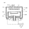
図1は、本実施の形態における枚葉式の成膜装置の概略構成図である。
Embodiment 1 FIG.
FIG. 1 is a schematic configuration diagram of a single wafer type film forming apparatus according to the present embodiment.
図1では、本実施の形態の成膜装置の構成の概略について、成膜室の模式的な断面図を用いて説明している。 In FIG. 1, an outline of a configuration of a film formation apparatus according to this embodiment is described using a schematic cross-sectional view of a film formation chamber.
本実施の形態においては、成膜処理の対象としてウェハ等の基板101を用いる。図1では、本実施の形態の成膜装置100のサセプタ102に基板101を載置した状態を示している。
In this embodiment mode, a
成膜装置100は、基板101上で気相成長をさせてエピタキシャル膜の成膜を行う成膜室として、チャンバ103を有する。
The
成膜装置100のチャンバ103の上部には、原料ガス供給部として機能するガス供給部123が設けられている。チャンバ103上部のガス供給部123には、ガス流路131、132が接続しており、ガス流路131、132の他方は、例えば、ガスボンベを用いて構成されたガス貯蔵部133、134に接続されている。ガス流路131、132の途中にはそれぞれ、ガスの流量を調整してガスの供給量の調整が可能なガスバルブ135、136が接続されている。ガス貯蔵部133には、基板101上で行うエピタキシャル膜の成膜のための原料ガス137が貯蔵されている。一方、ガス貯蔵部134には、キャリアガス138が貯蔵されている。したがって、ガスバルブ135は、ガス供給部123からチャンバ103内に供給される原料ガス137の制御用として設けられている。一方、ガスバルブ136は、ガス供給部123からチャンバ103内に供給されるキャリアガス138の制御用として設けられている。
A
成膜装置100は、チャンバ103内に供給されるガスを制御するための制御部であるガス制御部140を有する。ガス制御部140は、ガスバルブ135、136に接続している。ガス制御部140は、ガスバルブ135、136を制御し、ガス供給部123からチャンバ103内に供給される原料ガス137およびキャリアガス138を制御する。そして、高温に加熱された基板101の表面にエピタキシャル膜を成長させて成膜するための原料ガス137を供給する。
The
ガス供給部123には、原料ガス137等の吐出孔が多数形成されたシャワープレート124が接続している。シャワープレート124を基板101の表面と対向して上部に配置することにより、基板101の表面に原料ガス137が供給される。
Connected to the
チャンバ103の下部には、反応後の原料ガス137等を排気するためのガス排気部125が複数設けられている。ガス排気部125は、調整バルブ126および真空ポンプ127からなる排気機構128に接続している。また、排気機構128は、図示しない制御機構により制御されてチャンバ103内を所定の圧力に調整する。
A plurality of
チャンバ103の内部には、サセプタ102が、回転部104の上方に設けられている。サセプタ102は、開口部を有して構成されたリング状の形状を有する。そして、サセプタ102は、サセプタ102の内周側に座ぐりが設けられ、この座ぐり内に基板101の外周部を受け入れて支持する構造を有する。また、サセプタ102は、高温下にさらされることから、例えば、等方性黒鉛の表面にCVD法によって高耐熱な高純度のSiCを被覆して構成される。
A
尚、サセプタ102の構造について、図1に示すサセプタ102は一例であり、これに限られるものではない。
In addition, about the structure of the
図2は、本実施の形態の成膜装置のサセプタの別の例の構造を説明する模式的な拡大断面図である。 FIG. 2 is a schematic enlarged cross-sectional view for explaining the structure of another example of the susceptor of the film forming apparatus of the present embodiment.
サセプタ102の別の例であるサセプタ102aは、その内周側に、座ぐりの上方に張り出すように形成された張り出し部150を有する。このサセプタ102aの張り出し部150は、後述するように、サセプタ102a上に載置する基板101の少なくとも一部がサセプタ102a上から浮いた状態で回転された場合、基板101がサセプタ102a上から外れて飛び出すことがないように、基板101のサセプタ102a上での大きな上下動を抑制するように機能する。
A susceptor 102a, which is another example of the
回転部104は、円筒部104aと回転軸104bを有している。回転部104では、円筒部104aの上部でサセプタ102を支持している。そして、回転軸104bが図示しないモータによって回転することにより、円筒部104aを介してサセプタ102が回転する。こうして、サセプタ102の上に基板101が載置された場合、その基板101を回転させることができる。
The
図1において、円筒部104aは、上部が開口する構造を有し、上部が解放された構造である。そして、円筒部104aの上部にサセプタ102が配置され、サセプタ102上に基板101が載置されることにより、上部が覆われて中空領域(以下、P2領域と称す。)を形成する。ここで、チャンバ103内をP1領域とすると、P2領域は、基板101とサセプタ102によって実質的にP1領域と隔てられた領域となる。そのため、後述するインヒータ120とアウトヒータ121周囲のP2領域で発生した汚染物質によって基板101が汚染されるのを防ぐことができる。また、P1領域にある原料ガス137や、原料ガス137とともに用いられるキャリアガス138がP2領域内に進入し、P2領域内に配置されたインヒータ120とアウトヒータ121に接触することを防ぐことができる。
In FIG. 1, a
ここで、本実施の形態の成膜装置100では、後述するように、開口する上部がP2領域まで伸びているガス導入管111からP2領域にパージガス151を供給するように構成されている。成膜装置100は、ガス導入管111からP2領域にパージガス151を供給することが可能である。
Here, in the
そして、成膜装置100では、図1に示すように、円筒部104aの底部近傍の側壁部分には、その側壁を貫通する貫通孔を設けることが可能である。この貫通孔は、P2領域に供給されたパージガス151を排出する排出部155を構成する。
円筒部104aでは、排出部155からの排出が可能な量でP2領域にパージガス151を供給し、インヒータ120とアウトヒータ121の周囲をパージすることができる。その場合でも、P2領域に供給されたパージガス151は、排出部155から排出され、P2領域とP1領域とが隔てられた状態は実質的に維持される。
And in the film-forming
The
P2領域には、ヒータとしてのインヒータ120とアウトヒータ121が設けられている。インヒータ120およびアウトヒータ121には抵抗加熱ヒータを用いることが可能であり、それらはカーボン(C)材の表面に高耐熱なSiCを被覆して構成される。これらのヒータは、回転軸104b内に設けられた略円筒状の石英製のシャフト108の内部を通る配線109によって給電され、サセプタ102を介して基板101をその裏面から加熱する。アウトヒータ121は周囲の部材に熱が逃げやすい基板101の外周部の加熱を主な目的とする。インヒータ120とは別にアウトヒータ121を設けて2重ヒータとすることにより、基板101の加熱における面内均一性を向上させることができる。
The area P 2,
加熱により変化する基板101の表面温度は、チャンバ103の上部に設けられた放射温度計122によって計測される。尚、シャワープレート124を透明石英製とすることによって、放射温度計122による温度測定が、シャワープレート124で妨げられないようにすることができる。計測した温度データは、図示しない制御機構に送られた後、インヒータ120およびアウトヒータ121の出力制御にフィードバックされる。これにより、基板101を所望の温度となるように加熱できる。
The surface temperature of the
シャフト108の内部には、基板昇降手段として昇降ピン110が配置されている。昇降ピン110の下端は、シャフト108の下部に設けられた図示されない昇降装置まで伸びている。そして、その昇降装置を動作させて昇降ピン110を上昇または下降させることができる。この昇降ピン110は、基板101のチャンバ103内への搬入とチャンバ103外への搬出の時に使用される。昇降ピン110は基板101を下方から支持し、持ち上げてサセプタ102から引き離す。そして、基板101搬送用ロボット(図示されない)との間で基板101の受け渡しができるように、基板101を回転部104上のサセプタ102から離れた上方の所定の位置に配置するように動作する。
Inside the
シャフト108の内部にはさらに、円筒部104aの内部のP2領域にパージガス151を供給するパージガス供給部として、開口する上部がP2領域まで伸びているガス導入管111が配置されている。ガス導入管111にはガス流路152が接続しており、ガス流路152の他方は、例えば、ガスボンベを用いて構成されたガス貯蔵部153に接続されている。ガス貯蔵部153には、P2領域に供給されるパージガス151が貯蔵されている。
Further inside of the
ガス流路152の途中には、ガスの流量を調整してガスの供給量の調整が可能なガスバルブ154が接続されている。ガスバルブ154は、上述したガス制御部140に接続している。したがって、成膜装置100では、ガス制御部140がガスバルブ154を制御し、ガス導入管111からP2領域に供給されるパージガス151を制御する。そして、ガス制御部140は、基板101の表面にエピタキシャル膜を成長させるための原料ガス137を制御するとともに、キャリアガス138を制御し、さらに、P2領域に供給されてP2領域をパージするパージガス151を制御する。
A
ガス貯蔵部153に貯蔵され、ガス制御部140の制御によって、ガス導入管111からP2領域に供給可能なパージガス151としては、アルゴン(Ar)ガスおよびヘリウム(He)ガス等の不活性ガスの他、水素(H2)ガスや窒素(N2)ガス等を挙げることができる。それらパージガスを1種のみ使用することが可能であり、2種以上のパージガスを同時に使用することも可能である。
The
本実施の形態の成膜装置100では、基板101上でエピタキシャル膜を成長させて成膜する成膜工程において、ガス制御部140を用い、P1領域への供給される原料ガス137とP2領域をパージするパージガス151とをそれぞれ制御することができる。そして、成膜装置100では、パージガス151の供給を、原料ガス137の供給と一緒に行うようにすることができる。
In the
したがって、成膜装置100は、サセプタ102上に載置された基板101を回転させながら、円筒部104aのP2領域にパージガス151を供給することができる。そして、P2領域に供給されたパージガス151が、基板101とサセプタ102の間から抜け出るようにすることによって、基板101の少なくとも一部がサセプタ102から浮いた状態を形成することができる。成膜装置100では、基板101の少なくとも一部がサセプタ102から浮いた状態で基板101を回転するようにし、P1領域へ供給される原料ガス137を用いて基板101上でエピタキシャル膜を成膜することができる。
Accordingly, the
成膜装置100は、上述のように、円筒部104aのP2領域にパージガス151を供給し、回転する基板101の少なくとも一部がサセプタ102から浮いた状態を形成する。成膜装置100では、上述のように排出部155が設けられることがある。そして、基板101の浮いた状態の形成前から、排出部155からの排出が可能な量でP2領域にパージガス151を供給し、インヒータ120とアウトヒータ121の周囲をパージするようにする場合がある。その場合、基板101の浮いた状態の形成前までにP2領域に供給されていたパージガス151の供給量を一時的に増やすことで、基板101の少なくとも一部がサセプタ102から浮くようにすることができる。
成膜装置100は、例えば、チャンバ103のP1領域と円筒部104aのP2領域で、圧力がほぼ等しくなるように構成される。そして、P1領域にある原料ガス137や、原料ガス137とともに用いられるキャリアガス138がP2領域内に進入しないように、P2領域の圧力が若干高くなるように設定される。例えば、チャンバ103内が減圧状態にされ、P1領域の圧力が300Torrに設定された場合、円筒部104aのP2領域の圧力は301Torr〜305Torr程度に設定される。そのため、P2領域内に供給されるパージガス151の流量は、5リットル/分程度またはそれ以下となる量が設定される。そして、成膜装置100では、基板101を回転させてエピタキシャル膜を成膜する工程において、常時、こうした流量のパージガス151をP2領域内に供給することが可能である。
Film-forming
そして、円筒部104aのP2領域にパージガス151を供給し、回転する基板101の少なくとも一部がサセプタ102から浮いた状態を形成する。その場合、ガス制御部140の制御によってパージガス151の供給量を、常時供給されている量から一時的に増大し、そうした状態を形成することができる。例えば、パージガス151の供給量を一時的に増やして6リットル/分〜10リットル/分の流量とし、基板101の少なくとも一部がサセプタ102から浮くようにすることができる。
Then, the
基板101の少なくとも一部がサセプタ102から浮いた状態は一時的なものとすることが可能である。そして、そのような状態が形成された後の成膜装置100では、基板101とサセプタ102の間からパージガス151が抜け出すことにより、基板101はサセプタ102上の位置に戻ることになる。こう変動を繰り返すことにより、基板101はサセプタ102上で微小に上下に振動している状態を形成することができる。このとき、基板101は、サセプタ102の回転に伴って高速に回転している。したがって、基板101は、微小に上下に振動しながら高速回転する状態となる。
A state in which at least a part of the
成膜装置100は、成膜工程において、上述のような状態を形成ながら、回転する基板101上でエピタキシャル膜を成膜することができる。その場合、サセプタ102の座ぐり内に受け入れられた基板101の外周部は、その座ぐり部分との間で、対向する部分同士が同じ接触状態のまま維持されて成膜処理されることはなくなる。
In the film forming process, the
上述したように、成膜装置100は、チャンバ103内で気相成長をさせるとき、基板101の表面のみではなく、基板101を支持しているサセプタ102の表面にも原料ガス137に起因する薄膜が形成される。上述した従来の成膜装置では、そうしたことが成膜処理中に繰り返されると、サセプタ上に形成された薄膜によって基板がサセプタに接着されたような状態となる問題があった。
As described above, when the
しかしながら、本実施の形態の成膜装置100は、円筒部104aのP2領域に供給されたパージガス151を利用し、基板101を微小に上下に振動しながら高速回転させることができる。したがって、基板101とサセプタ102との間に原料ガス137に起因する薄膜が形成されても、基板101がサセプタ102に貼り付くことを防止することができる。
However, the
実施の形態2.
次に、本実施の形態の成膜方法の一例について説明する。本実施の形態の成膜方法は、図1に示した成膜装置100を用いて行うことができる。したがって、図1等の図面を適宜参照しながら説明する。
Embodiment 2. FIG.
Next, an example of a film formation method of this embodiment will be described. The film formation method of this embodiment can be performed using the
本実施の形態の成膜方法は、気相成長をさせて基板101上にエピタキシャル膜を成膜する。そして、その成膜処理に際し、基板101とサセプタ102との間に原料ガス137に起因する薄膜が形成されても、基板101がサセプタ102に貼り付くことを防止することができる。尚、基板101の直径は、例えば、200mmまたは300mmとすることができる。
In the film formation method of this embodiment mode, an epitaxial film is formed on the
基板101の、成膜装置100のチャンバ103内への搬入は、図示しない搬送用ロボットを用いて行う。基板101の搬入に際し、ガス制御部140の制御によって、開口する上部がP2領域まで伸びているガス導入管111からP2領域にパージガス151を供給することが可能である。パージガス151の流量としては、基板101をサセプタ102上に載置するのに好適な流量が選択される。すなわち、P2領域に供給されたパージガス151が、基板101とサセプタ102の間から抜け出て、基板101の少なくとも一部がサセプタ102から浮いた状態を形成することがないように流量が設定されることが好ましい。例えば、P2領域に供給されるパージガス151の流量は、5リットル/分程度またはそれ以下となる量が設定される。
The
パージガス151としては、上述したガスの使用が可能である。そして、カーボン材から構成されるインヒータ120およびアウトヒータ121に接触してもそれらに損傷を与えることの少ないアルゴンガスおよび窒素ガスのうちの少なくとも一方を選択して使用することが好ましい。
As the
成膜装置100の回転部104の内部には、図1に示したように、回転軸104bの内部を貫通する昇降ピン110が設けられている。搬送用ロボットからの基板101の受け取りは、この昇降ピン110が用いられる。
昇降ピン110を初期位置から上昇させ、サセプタ102上方の所定の位置で、搬送用ロボットから昇降ピン110が基板101を受け取った後、基板101を支持した状態で昇降ピン110を下降させる。
As shown in FIG. 1, ascending / descending
The lift pins 110 are raised from the initial position, and after the lift pins 110 receive the
そして、図1に示したように、昇降ピン110を所定の初期位置に戻す。こうして、基板101は、回転部104の円筒部104a上のサセプタ102の上に載置される。
And as shown in FIG. 1, the raising / lowering
次に、チャンバ103内を常圧の状態または適当な減圧の状態にし、ガス制御部140の制御によってガス供給部123からP1領域にキャリアガス138である水素ガスを供給する。そして、キャリアガス138を流しながら、回転部104に付随させて、基板101を50rpm程度で回転させる。
Next, the inside of the
ガス導入管111からは、ガス制御部140の制御によって、上述した流量のパージガス151が円筒部104aのP2領域内に供給されている。P2領域に供給されたパージガス151は、P2領域内をパージして、排出部155から排出される。P2領域は、実質的にP1領域と隔てられた領域となる。
From the
尚、P2領域を形成する円筒部104aが、排出部155を有して構成されていない場合には、パージガス151の供給を停止するか、ごく少ない流量とすることができる。そのようにしても、P2領域は実質的にP1領域と隔てられた領域となる。そして、基板101をサセプタ102上に安定して載置することができる。
Incidentally, the
次に、インヒータ120およびアウトヒータ121によって基板101を1100℃〜1200℃に加熱する。例えば、成膜温度である1150℃まで徐々に加熱する。
Next, the
放射温度計122による測定で基板101の温度が1150℃に達したことを確認した後は、徐々にサセプタ102上の基板101の回転数を上げていくようにする。そして、ガス制御部140の制御によって、ガス供給部123からシャワープレート124を介して原料ガス137をチャンバ103の内部に供給する。本実施の形態においては、原料ガス137としてトリクロロシランを用いることができ、ガス制御部140の制御によって、キャリアガス138としての水素ガスと混合した状態で、ガス供給部123からチャンバ103の内のP1領域に導入する。
After confirming that the temperature of the
そして、本実施の形態の成膜方法では、ガス制御部140の制御によって、ガス供給部123からP1領域への原料ガス137の供給が開始されるとともに、ガス導入管111からP2領域内に供給されているパージガス151の供給量を増大させるようにする。そして、パージガス151が基板101とサセプタ102の間から抜け出るようにすることによって、基板101の少なくとも一部がサセプタ102から浮くようにし、その状態で基板101を回転するようにする。その結果、上述したように、基板101は、微小に上下に振動しながら高速回転する状態となる。
In the film forming method of the present embodiment, the supply of the
尚、ガス供給部123からP1領域への原料ガス137の供給の開始前に、ガス導入管111からP2領域へのパージガス151の供給が停止されていた場合には、P1領域への原料ガス137の供給の開始とともに、ガス導入管111からP2領域へパージガス151を供給するようにする。そして、基板101の少なくとも一部がサセプタ102から浮くようにし、その状態で基板101を回転するようにする。
Incidentally, before the start of the
チャンバ103の内部のP1領域に導入された原料ガス137は、基板101の方に流下する。一方、基板101は、ガス制御部140の制御による円筒部104aのP2領域へのパージガス151の供給により、上述のように、微小に上下に振動しながら高速回転をしている。
The
そして、基板101の温度を1150℃に維持し、円筒部104a上のサセプタ102を900rpm以上の高速で回転させながら、ガス供給部123からシャワープレート124を介して次々に新たな原料ガス137を基板101に供給する。これにより、基板101上での気相成長が促進され、高い成膜速度で効率良くエピタキシャル膜を成膜させることができる。
Then, while maintaining the temperature of the
このように、原料ガス137を導入しつつサセプタ102を回転させることにより、基板101の上に均一な厚さのシリコンのエピタキシャル層を成長させることができる。例えば、パワー半導体の用途では、300mmの基板上に10μm以上、多くは10μm〜100μm程度の厚膜が形成される。厚膜を形成するには、成膜時の基板の回転数を高くするのがよく、例えば、上記のように900rpm程度の回転数とするのがよい。
Thus, by rotating the
そして、本実施の形態の成膜方法では、上述したように、チャンバ103内で気相成長をさせるとき、基板101の表面のみではなく、基板101を支持しているサセプタ102の表面にも原料ガス137に起因する薄膜が形成される。
In the film forming method of this embodiment, as described above, when vapor phase growth is performed in the
しかしながら、本実施の形態の成膜装置100は、ガス制御部140の制御により円筒部104aのP2領域に供給されたパージガス151を利用することができる。そして、上述のように、基板101を微小に上下に振動しながら高速回転させることができる。したがって、基板101とサセプタ102との間に原料ガス137に起因する薄膜が形成されても、基板101がサセプタ102に貼り付くことを防止することができる。
However, the
基板101上に所定の膜厚のエピタキシャル膜を成膜した後は、インヒータ120およびアウトヒータ121による加熱を停止し、ガス供給部123からの原料ガス137の供給を終了する。キャリアガス138の供給も、原料ガス137の供給終了とともに終了することができるが、ガス制御部140の制御によって、基板101の温度が所定の値より低くなるまで供給を継続することも可能である。
After the epitaxial film having a predetermined thickness is formed on the
そして、原料ガス137の供給終了とともに、P2領域内に供給されているパージガス151の供給量を増大させることも終了し、パージガス151の流量を増大される前の状態に戻すようにする。
Then, the supply end of the
基板101上でのエピタキシャル膜の成膜を終了し、エピタキシャル膜の成膜された基板101が所定の温度まで降温した後、基板101はチャンバ103の外に搬出される。その場合、まず昇降ピン110を上昇させる。そして、基板101を下方側から支持した後、昇降ピン110をさらに上昇させて、サセプタ102から持ち上げて引き離すようにする。このとき、本実施の形態の成膜方法によって成膜処理された基板101では、基板101がサセプタ102に貼り付くことが防止されている。したがって、昇降ピン110は、エピタキシャル膜の成膜された基板101を容易にサセプタ102から引き離すことができ、基板101や基板101上のエピタキシャル膜を損傷させることはない。
After the epitaxial film formation on the
そして、昇降ピン110は搬送用ロボット(図示されない)に基板101を受け渡す。基板101を受け渡された搬送用ロボットは、その基板101をチャンバ103の外に搬出する。
The lift pins 110 deliver the
尚、本実施の形態の成膜方法では、上述したように、ガス制御部140の制御によって、P2領域へのキャリアガス138の供給が開始されるとともに、P2領域内に供給されているパージガス151の供給量を増大させるようにすることができる。しかし、パージガス151の供給量の増大は、ガス制御部140の制御によって、その前から行うように制御することも可能である。例えば、基板101を、上述したように、50rpm程度で回転させた後、インヒータ120およびアウトヒータ121によって基板101を成膜温度まで徐々に加熱するとき、パージガス151の供給量を増大させることができる。
In the film-forming method of this embodiment, as described above, the control of
また、本実施の形態の成膜方法は、ガス制御部140の制御によって、例えば、ガス供給部123からP1領域への原料ガス137の供給が開始されるとともに、ガス導入管111からP2領域内に供給されているパージガス151の供給量を増大させるようにしている。そして、原料ガス137を供給して高温状態の基板101上でエピタキシャル膜を成膜する工程において、P1領域への原料ガス137の供給の後、パージガス151の供給量が増大された状態を継続して維持することができる。
In the film forming method of the present embodiment, for example, the supply of the
しかし、本実施の形態の成膜方法では、必ずしもパージガス151の供給量が一時的に増大されるパージガス増大期間を連続する1つの期間とする必要はない。
例えば、本実施の形態の成膜方法の別の例として、原料ガス137を供給して高温状態の基板101上でエピタキシャル膜を成膜する工程において、ガス制御部140の制御によって、パージガス増大期間を不連続に複数回設けることも可能である。
However, in the film forming method of this embodiment, the purge gas increase period in which the supply amount of the
For example, as another example of the film forming method of the present embodiment, the purge gas increase period is controlled under the control of the
そうした本実施の形態の成膜方法の別の例では、パージガス増大期間を、パージガス151の供給量が増大前の状態に戻される期間を挟んで、複数回設けるようにすることが可能である。
In another example of the film forming method of this embodiment, the purge gas increase period can be provided a plurality of times with a period during which the supply amount of the
このようにしても、パージガス151の供給量が増大される間に、高温に加熱された基板101を微小に上下に振動しながら高速回転させる期間を設けることができ、基板101とサセプタ102との間に原料ガス137に起因する薄膜が形成されても、基板101がサセプタ102に貼り付くことを防止することができる。
Even in this case, while the supply amount of the
また、本実施の形態の成膜方法では、上述のように、高温状態の基板101を高速回転させて、基板101上にエピタキシャル膜を成膜させる場合、原料ガス137の供給を連続的に行うことが可能である。しかし、成膜速度を向上させてより効率良くエピタキシャル膜を成膜させるため、高温状態の基板101上でエピタキシャル膜を成膜する工程において、原料ガス137の供給期間を不連続とすることもできる。すなわち、高温状態の基板101上に原料ガス137を供給してエピタキシャル膜を成膜する工程において、原料ガス137の供給を一定期間停止するガス停止期間を少なくとも1回設けることも可能である。こうしたガス停止期間を設けることにより、基板101上での気相成長反応の飽和が回避され、結果として、基板101上でのより効率的なエピタキシャル膜の成膜が可能となる。
In the film formation method of this embodiment, as described above, when the epitaxial film is formed on the
そして、本実施の形態の成膜方法で、ガス制御部140の制御によってそうしたガス停止期間を設ける場合、上述した本実施の形態の成膜方法の別の例では、ガス停止期間中にパージガス増大期間を設けるようにすることが可能である。
When such a gas stop period is provided by the control of the
図3は、本実施の形態の成膜方法の別の例を説明するグラフである。 FIG. 3 is a graph for explaining another example of the film forming method of the present embodiment.
図3は、本実施の形態の成膜方法の別の例において、ガス制御部140の制御によって制御され、ガス導入管111からP2領域内に供給されるパージガス151の流量が経時的に変化する状況を示している。
3, in another example of a film forming method of this embodiment is controlled by the control of the
すなわち、本実施の形態の成膜方法の別の例では、高温加熱された基板101上でエピタキシャル膜を成膜する工程において、ガス制御部140の制御により、原料ガス137の供給を行うガス供給期間を不連続に複数回設けることが可能である。そして、複数のガス供給期間の間には、ガス制御部140の制御により、原料ガス137の供給を一定期間停止するガス停止期間を設けることが可能である。本実施の形態の成膜方法の別の例では、そのガス停止期間内に、ガス停止期間と同じかそれより短い期間の間、パージガス増大期間を設けることが可能である。
That is, in another example of the film forming method of the present embodiment, in the step of forming an epitaxial film on the
このようにしても、パージガス増大期間では、高温に加熱された基板101を微小に上下に振動しながら高速に回転させることができる。したがって、基板101とサセプタ102との間に原料ガス137に起因する薄膜が形成されても、基板101がサセプタ102に貼り付くことを防止することができる。
Even in this case, during the purge gas increase period, the
そして、ガス停止期間以外の、原料ガス137が供給されるガス供給期間では、パージガス151の供給量が増大されることはなく、増大前のパージガス151の供給量が維持され、基板101の微小な上下動の発生が抑えられている。したがって、本実施の形態の成膜方法の別の例では、基板101がサセプタ102に貼り付くことを防止するとともに、より安定した条件下で、より効率良く高品位のエピタキシャル膜を成膜することが可能となる。
In addition, in the gas supply period in which the
尚、上述したように、P2領域を形成する円筒部104aが排出部155を有しない場合には、パージガス151の供給を停止するか、ごく少ない流量とし、P2領域を実質的にP1領域と隔てられた領域としている。その場合には、本実施の形態の成膜方法のさらに別の例として、ガス停止期間中にパージガス151の供給を開始し、パージガス151を供給するパージガス供給期間を設けるようにすることが可能である。
As described above, when the
図4は、本実施の形態の成膜方法のさらに別の例を説明するグラフである。 FIG. 4 is a graph illustrating still another example of the film forming method of the present embodiment.
図4は、ガス制御部140によって制御され、P2領域内にパージガス151が供給されるパージガス供給期間が不連続に設けられ、P2領域内に供給されるパージガス151の流量が経時的に変化する状況を示している。
Figure 4 is controlled by the
すなわち、本実施の形態の成膜方法のさらに別の例では、高温加熱された基板101上でエピタキシャル膜を成膜する工程において、ガス制御部140の制御により、原料ガス137の供給を行うガス供給期間を不連続に複数回設けることが可能である。そして、複数のガス供給期間の間には、ガス制御部140の制御により、原料ガス137の供給を一定期間停止するガス停止期間を設けることが可能である。本実施の形態の成膜方法のさらに別の例では、そのガス停止期間内に、ガス停止期間と同じかそれより短い期間の間、一時的にパージガス151をP2領域に供給するパージガス供給期間を設けることが可能である。
That is, in yet another example of the film forming method of the present embodiment, in the step of forming an epitaxial film on the
このようにしても、パージガス151が供給されるパージガス供給期間では、高温に加熱された基板101を微小に上下に振動しながら高速回転させることができる。したがって、基板101とサセプタ102との間に原料ガス137に起因する薄膜が形成されても、基板101がサセプタ102に貼り付くことを防止することができる。
Even in this case, in the purge gas supply period in which the
そして、ガス停止期間以外の、原料ガス137が供給されるガス供給期間では、パージガス151が供給されることはなく、基板101の微小な上下動の発生が抑えられている。したがって、本実施の形態の成膜方法のさらに別の例では、基板101がサセプタ102に貼り付くことを防止するとともに、より安定した条件下で、より効率良く高品位のエピタキシャル膜を成膜することが可能となる。
In the gas supply period in which the
尚、本発明は上記各実施の形態に限定されるものではなく、本発明の趣旨を逸脱しない範囲内で種々変形して実施することができる。 The present invention is not limited to the above-described embodiments, and various modifications can be made without departing from the spirit of the present invention.
例えば、上記各実施の形態では、成膜装置の一例としてエピタキシャル膜の成膜装置を挙げたが、本発明はこれに限られるものではない。成膜室内に原料ガスを供給し、成膜室内に載置される半導体基板を加熱して半導体基板の表面に膜を形成する成膜装置であれば、CVD装置等の他の成膜装置であってもよい。 For example, in each of the embodiments described above, an epitaxial film forming apparatus has been described as an example of the film forming apparatus, but the present invention is not limited to this. A film forming apparatus that supplies a source gas into the film forming chamber and heats the semiconductor substrate placed in the film forming chamber to form a film on the surface of the semiconductor substrate. There may be.
100、1100 成膜装置
101 基板
102、102a、1102 サセプタ
103、1103 チャンバ
104、1104 回転部
104a、1104a 円筒部
104b、1104b 回転軸
108、1108 シャフト
109、1109 配線
110 昇降ピン
111 ガス導入管
120 インヒータ
121 アウトヒータ
122 放射温度計
123、1123 ガス供給部
124、1124 シャワープレート
125、1125 ガス排気部
126、1126 調整バルブ
127、1127 真空ポンプ
128、1128 排気機構
131、132、152 ガス流路
133、134、153 ガス貯蔵部
135、136、154 ガスバルブ
137 原料ガス
138 キャリアガス
140 ガス制御部
150 張り出し部
151 パージガス
155 排出部
1101 ウェハ
1120 ヒータ
DESCRIPTION OF
Claims (5)
前記成膜室内に原料ガスを供給し、
前記治具を上部で支持する円筒部を備えた回転部を回転させることにより、前記基板を回転させ、
前記円筒部にパージガスを供給し、
前記パージガスが前記基板と前記治具との間から抜け出て、前記基板が上下に振動するように前記パージガスの供給量を制御することを特徴とする成膜方法。 Place the substrate on the jig placed in the deposition chamber,
The raw material gas is supplied into the film forming chamber,
By rotating a rotating part having a cylindrical part that supports the jig at the top, the substrate is rotated,
Supplying purge gas to the cylindrical portion;
Film forming method characterized in that the purge gas exits from between the substrate and the jig, the substrate to control the supply amount of the purge gas to vibrate up and down.
前記成膜室内に原料ガスを供給する原料ガス供給部と、A source gas supply unit for supplying source gas into the film forming chamber;
前記成膜室内に配置されて基板が載置される治具と、A jig placed in the film forming chamber and on which a substrate is placed;
前記治具を上部で支持する円筒部を備えた回転部と、A rotating part having a cylindrical part for supporting the jig at the upper part;
前記円筒部内にパージガスを供給するパージガス供給部と、A purge gas supply part for supplying a purge gas into the cylindrical part;
前記原料ガスの供給と前記パージガスの供給を制御する制御部とを有し、A control unit for controlling the supply of the source gas and the supply of the purge gas,
前記制御部は、前記パージガスの一部が前記基板と前記治具の間から抜け出て前記基板が上下に振動するように前記パージガスの供給量を制御することを特徴とする成膜装置。The control unit controls the supply amount of the purge gas so that a part of the purge gas escapes between the substrate and the jig and the substrate vibrates up and down.
Priority Applications (3)
| Application Number | Priority Date | Filing Date | Title |
|---|---|---|---|
| JP2011238285A JP5794893B2 (en) | 2011-10-31 | 2011-10-31 | Film forming method and film forming apparatus |
| US13/661,362 US20130104800A1 (en) | 2011-10-31 | 2012-10-26 | Film-forming method and film-forming apparatus |
| KR1020120119641A KR101447663B1 (en) | 2011-10-31 | 2012-10-26 | Film-forming method and film-forming apparatus |
Applications Claiming Priority (1)
| Application Number | Priority Date | Filing Date | Title |
|---|---|---|---|
| JP2011238285A JP5794893B2 (en) | 2011-10-31 | 2011-10-31 | Film forming method and film forming apparatus |
Publications (3)
| Publication Number | Publication Date |
|---|---|
| JP2013098271A JP2013098271A (en) | 2013-05-20 |
| JP2013098271A5 JP2013098271A5 (en) | 2014-10-02 |
| JP5794893B2 true JP5794893B2 (en) | 2015-10-14 |
Family
ID=48171078
Family Applications (1)
| Application Number | Title | Priority Date | Filing Date |
|---|---|---|---|
| JP2011238285A Active JP5794893B2 (en) | 2011-10-31 | 2011-10-31 | Film forming method and film forming apparatus |
Country Status (3)
| Country | Link |
|---|---|
| US (1) | US20130104800A1 (en) |
| JP (1) | JP5794893B2 (en) |
| KR (1) | KR101447663B1 (en) |
Families Citing this family (7)
| Publication number | Priority date | Publication date | Assignee | Title |
|---|---|---|---|---|
| JP2018037537A (en) * | 2016-08-31 | 2018-03-08 | 株式会社ニューフレアテクノロジー | Vapor growth device |
| JP6998839B2 (en) * | 2018-06-25 | 2022-01-18 | グローバルウェーハズ・ジャパン株式会社 | Manufacturing method of epitaxial silicon wafer |
| JP2020043260A (en) * | 2018-09-12 | 2020-03-19 | 住友金属鉱山株式会社 | Polycrystalline film forming method, substrate mounting mechanism, and film forming apparatus |
| DE102019132933A1 (en) * | 2018-12-10 | 2020-06-10 | Showa Denko K.K. | SUSCEPTOR AND DEVICE FOR CHEMICAL GAS PHASE DEPOSITION |
| JP7382836B2 (en) * | 2020-01-15 | 2023-11-17 | 東京エレクトロン株式会社 | Substrate processing equipment and rotational drive method |
| JP2021082824A (en) * | 2021-01-27 | 2021-05-27 | 株式会社ニューフレアテクノロジー | Vapor phase growth apparatus |
| KR102570336B1 (en) * | 2021-03-22 | 2023-08-25 | 김용한 | Apparatus for manufacturing a gallium nitride substrate |
Family Cites Families (14)
| Publication number | Priority date | Publication date | Assignee | Title |
|---|---|---|---|---|
| JP3061401B2 (en) * | 1990-07-20 | 2000-07-10 | 株式会社東芝 | Semiconductor vapor deposition equipment |
| JP2990551B2 (en) * | 1992-01-16 | 1999-12-13 | 東京エレクトロン株式会社 | Film processing equipment |
| US5960555A (en) * | 1996-07-24 | 1999-10-05 | Applied Materials, Inc. | Method and apparatus for purging the back side of a substrate during chemical vapor processing |
| US6133152A (en) * | 1997-05-16 | 2000-10-17 | Applied Materials, Inc. | Co-rotating edge ring extension for use in a semiconductor processing chamber |
| JP2001053030A (en) * | 1999-08-11 | 2001-02-23 | Tokyo Electron Ltd | Film forming device |
| WO2001071784A1 (en) * | 2000-03-17 | 2001-09-27 | Hitachi, Ltd. | Method of manufacturing semiconductor and manufacturing apparatus |
| JP4614252B2 (en) * | 2001-02-15 | 2011-01-19 | キヤノンアネルバ株式会社 | Substrate processing apparatus and computer program used therefor |
| WO2003046966A1 (en) * | 2001-11-30 | 2003-06-05 | Shin-Etsu Handotai Co., Ltd. | Susceptor, gaseous phase growing device, device and method for manufacturing epitaxial wafer, and epitaxial wafer |
| KR100534209B1 (en) * | 2003-07-29 | 2005-12-08 | 삼성전자주식회사 | chemical vapor deposition fabricating equipment for manufacturing of semiconductor device |
| US8148271B2 (en) * | 2005-08-05 | 2012-04-03 | Hitachi Kokusai Electric Inc. | Substrate processing apparatus, coolant gas supply nozzle and semiconductor device manufacturing method |
| JP4803578B2 (en) * | 2005-12-08 | 2011-10-26 | 東京エレクトロン株式会社 | Deposition method |
| JP5165952B2 (en) * | 2007-07-20 | 2013-03-21 | 株式会社ニューフレアテクノロジー | Vapor growth apparatus and vapor growth method |
| KR101405346B1 (en) * | 2008-01-04 | 2014-06-12 | 삼성디스플레이 주식회사 | Substrate pedestal, apparatus for treating substrate having it and the method for aligning substrate |
| KR101006647B1 (en) * | 2008-04-25 | 2011-01-10 | 가부시키가이샤 뉴플레어 테크놀로지 | Film forming apparatus and film forming method |
-
2011
- 2011-10-31 JP JP2011238285A patent/JP5794893B2/en active Active
-
2012
- 2012-10-26 KR KR1020120119641A patent/KR101447663B1/en not_active IP Right Cessation
- 2012-10-26 US US13/661,362 patent/US20130104800A1/en not_active Abandoned
Also Published As
| Publication number | Publication date |
|---|---|
| JP2013098271A (en) | 2013-05-20 |
| KR101447663B1 (en) | 2014-10-06 |
| US20130104800A1 (en) | 2013-05-02 |
| KR20130047620A (en) | 2013-05-08 |
Similar Documents
| Publication | Publication Date | Title |
|---|---|---|
| JP5794893B2 (en) | Film forming method and film forming apparatus | |
| JP5732284B2 (en) | Film forming apparatus and film forming method | |
| JP5038365B2 (en) | Susceptor and deposition system | |
| JP5038381B2 (en) | Susceptor and deposition system | |
| JP2009283904A (en) | Coating apparatus and coating method | |
| JP2007251078A (en) | Vapor phase epitaxial growth device | |
| JP6424726B2 (en) | Susceptor and epitaxial growth apparatus | |
| JP5204721B2 (en) | Film forming apparatus and film forming method | |
| JP6444641B2 (en) | Film forming apparatus, susceptor, and film forming method | |
| WO2012026241A1 (en) | Method for manufacturing semiconductor device, and substrate treatment device | |
| WO2019044392A1 (en) | Vapor-phase deposition method | |
| JP2012080035A (en) | Substrate processing device and substrate manufacturing method | |
| JP2011165964A (en) | Method of manufacturing semiconductor device | |
| JP2011021253A (en) | Film deposition system | |
| JP2009071210A (en) | Susceptor and epitaxial growth system | |
| JP4933409B2 (en) | Semiconductor manufacturing apparatus and semiconductor manufacturing method | |
| JP5306432B2 (en) | Vapor growth method | |
| JP5832173B2 (en) | Vapor growth apparatus and vapor growth method | |
| JP5208850B2 (en) | Deposition equipment | |
| JP2011151118A (en) | Apparatus and method for manufacturing semiconductor | |
| JP2011011942A (en) | Apparatus and method for producing crystal | |
| JP5358201B2 (en) | Deposition method | |
| JP5264384B2 (en) | Vapor growth apparatus and vapor growth method | |
| JP2013016562A (en) | Vapor-phase growth method | |
| JP5461943B2 (en) | Film forming apparatus and film forming method |
Legal Events
| Date | Code | Title | Description |
|---|---|---|---|
| A521 | Request for written amendment filed |
Free format text: JAPANESE INTERMEDIATE CODE: A523 Effective date: 20140818 |
|
| A621 | Written request for application examination |
Free format text: JAPANESE INTERMEDIATE CODE: A621 Effective date: 20140818 |
|
| A977 | Report on retrieval |
Free format text: JAPANESE INTERMEDIATE CODE: A971007 Effective date: 20150519 |
|
| A131 | Notification of reasons for refusal |
Free format text: JAPANESE INTERMEDIATE CODE: A131 Effective date: 20150526 |
|
| A521 | Request for written amendment filed |
Free format text: JAPANESE INTERMEDIATE CODE: A523 Effective date: 20150716 |
|
| TRDD | Decision of grant or rejection written | ||
| A01 | Written decision to grant a patent or to grant a registration (utility model) |
Free format text: JAPANESE INTERMEDIATE CODE: A01 Effective date: 20150804 |
|
| A61 | First payment of annual fees (during grant procedure) |
Free format text: JAPANESE INTERMEDIATE CODE: A61 Effective date: 20150811 |
|
| R150 | Certificate of patent or registration of utility model |
Ref document number: 5794893 Country of ref document: JP Free format text: JAPANESE INTERMEDIATE CODE: R150 |
|
| R250 | Receipt of annual fees |
Free format text: JAPANESE INTERMEDIATE CODE: R250 |
|
| R250 | Receipt of annual fees |
Free format text: JAPANESE INTERMEDIATE CODE: R250 |
|
| R250 | Receipt of annual fees |
Free format text: JAPANESE INTERMEDIATE CODE: R250 |
|
| R250 | Receipt of annual fees |
Free format text: JAPANESE INTERMEDIATE CODE: R250 |
|
| R250 | Receipt of annual fees |
Free format text: JAPANESE INTERMEDIATE CODE: R250 |
|
| R250 | Receipt of annual fees |
Free format text: JAPANESE INTERMEDIATE CODE: R250 |