JP5792751B2 - Tooling assembly, punching tool for tooling assembly, and related method - Google Patents
Tooling assembly, punching tool for tooling assembly, and related method Download PDFInfo
- Publication number
- JP5792751B2 JP5792751B2 JP2012557078A JP2012557078A JP5792751B2 JP 5792751 B2 JP5792751 B2 JP 5792751B2 JP 2012557078 A JP2012557078 A JP 2012557078A JP 2012557078 A JP2012557078 A JP 2012557078A JP 5792751 B2 JP5792751 B2 JP 5792751B2
- Authority
- JP
- Japan
- Prior art keywords
- tooling
- sheet
- shearing machine
- punching tool
- blanks
- Prior art date
- Legal status (The legal status is an assumption and is not a legal conclusion. Google has not performed a legal analysis and makes no representation as to the accuracy of the status listed.)
- Active
Links
Images


Classifications
-
- B—PERFORMING OPERATIONS; TRANSPORTING
- B21—MECHANICAL METAL-WORKING WITHOUT ESSENTIALLY REMOVING MATERIAL; PUNCHING METAL
- B21D—WORKING OR PROCESSING OF SHEET METAL OR METAL TUBES, RODS OR PROFILES WITHOUT ESSENTIALLY REMOVING MATERIAL; PUNCHING METAL
- B21D28/00—Shaping by press-cutting; Perforating
- B21D28/02—Punching blanks or articles with or without obtaining scrap; Notching
- B21D28/06—Making more than one part out of the same blank; Scrapless working
-
- B—PERFORMING OPERATIONS; TRANSPORTING
- B21—MECHANICAL METAL-WORKING WITHOUT ESSENTIALLY REMOVING MATERIAL; PUNCHING METAL
- B21D—WORKING OR PROCESSING OF SHEET METAL OR METAL TUBES, RODS OR PROFILES WITHOUT ESSENTIALLY REMOVING MATERIAL; PUNCHING METAL
- B21D22/00—Shaping without cutting, by stamping, spinning, or deep-drawing
- B21D22/20—Deep-drawing
- B21D22/28—Deep-drawing of cylindrical articles using consecutive dies
-
- B—PERFORMING OPERATIONS; TRANSPORTING
- B21—MECHANICAL METAL-WORKING WITHOUT ESSENTIALLY REMOVING MATERIAL; PUNCHING METAL
- B21D—WORKING OR PROCESSING OF SHEET METAL OR METAL TUBES, RODS OR PROFILES WITHOUT ESSENTIALLY REMOVING MATERIAL; PUNCHING METAL
- B21D51/00—Making hollow objects
- B21D51/16—Making hollow objects characterised by the use of the objects
- B21D51/26—Making hollow objects characterised by the use of the objects cans or tins; Closing same in a permanent manner
-
- Y—GENERAL TAGGING OF NEW TECHNOLOGICAL DEVELOPMENTS; GENERAL TAGGING OF CROSS-SECTIONAL TECHNOLOGIES SPANNING OVER SEVERAL SECTIONS OF THE IPC; TECHNICAL SUBJECTS COVERED BY FORMER USPC CROSS-REFERENCE ART COLLECTIONS [XRACs] AND DIGESTS
- Y10—TECHNICAL SUBJECTS COVERED BY FORMER USPC
- Y10T—TECHNICAL SUBJECTS COVERED BY FORMER US CLASSIFICATION
- Y10T83/00—Cutting
- Y10T83/04—Processes
- Y10T83/06—Blanking
-
- Y—GENERAL TAGGING OF NEW TECHNOLOGICAL DEVELOPMENTS; GENERAL TAGGING OF CROSS-SECTIONAL TECHNOLOGIES SPANNING OVER SEVERAL SECTIONS OF THE IPC; TECHNICAL SUBJECTS COVERED BY FORMER USPC CROSS-REFERENCE ART COLLECTIONS [XRACs] AND DIGESTS
- Y10—TECHNICAL SUBJECTS COVERED BY FORMER USPC
- Y10T—TECHNICAL SUBJECTS COVERED BY FORMER US CLASSIFICATION
- Y10T83/00—Cutting
- Y10T83/929—Tool or tool with support
- Y10T83/9411—Cutting couple type
- Y10T83/9447—Shear type
Description
<関連する出願の参照>
本願は、2010年3月10日に出願された米国仮特許出願第61/312,316号、発明の名称「ツーリングアセンブリ、ツーリングアセンブリ用打抜き工具、及び関連方法」の優先権を主張する。
<Reference to related applications>
This application claims priority to US Provisional Patent Application No. 61 / 312,316, filed March 10, 2010, entitled “Tooling Assembly, Tooling Assembly Tool, and Related Methods”.
開示された概念は、概して、ツーリングアセンブリ(tooling assemblies)に関するものであり、より具体的には、容器を作製するためのツーリングアセンブリに関している。開示された概念は、打抜き工具(blanking tools)と関連方法とにも関している。 The disclosed concept relates generally to tooling assemblies, and more specifically to a tooling assembly for making a container. The disclosed concept also relates to blanking tools and related methods.
シート状の金属ブランクを絞り加工(draw)及びしごき加工(iron)して、飲料(例えば、炭酸飲料、非炭酸飲料)、食料や他のものをパッケージングする薄肉の容器又は缶ボディを作製することは、一般によく知られている。従来より、カップ又は容器本体を作るためのツーリングアセンブリが、プレスのパンチとプレスダイとの間に運ばれる形成材料(例えば、シート状の金属ブランクがあるが、これに限定されない)に作用する。一般的には、ほぼ平坦なシート状の材料(例えば、これらに限定されないが、アルミニウムや鋼)が、通常、ロール(coil)又は積み重ねられたシートとして供給されて、ブランクが、当該シート状の材料から切り取られる(例えば、切断される)。次に、パンチが、ダイに向かって下方向に延びて、カップ又は缶ボディへとブランクを成形する。例えば、限定するものではないが、引用を以て本願の一部となる米国特許第7,124,613号及び第7,240,531号を参照のこと。 Sheet metal blanks are drawn and ironed to produce thin-walled containers or can bodies for packaging beverages (e.g. carbonated and non-carbonated beverages), food and other This is generally well known. Traditionally, tooling assemblies for making cups or container bodies act on forming materials (such as, but not limited to, sheet-like metal blanks) carried between a press punch and a press die. In general, a substantially flat sheet-like material (e.g., but not limited to aluminum or steel) is usually supplied as a coil or stacked sheet, and a blank is formed into the sheet-like material. Cut from material (eg, cut). The punch then extends downward toward the die to form a blank into a cup or can body. See, for example, but not limited to, US Pat. Nos. 7,124,613 and 7,240,531, which are incorporated herein by reference.
例えば、図1A及び図2は、図3に示すような材料(8)からブランク(6)を切り取る又はせん断する4点せん断機(4-point shear)(4)を有する従来の打抜き工具(2)を示している。具体的には、材料(8)がプレス(図示せず)に運ばれて、せん断機(4)が材料(8)に押しつけられて、ブランク(6)を切り出す又はせん断する(図3及び図4)。それにより、せん断機(4)、特に、せん断機(4)の幾つかの高い部分(10)(12)(14)(16)(18)(20)(22)(24)(例えば、図2に最もよく示されているように、打抜き工具(2)の底から外向きに広がった面)は、材料(8)に係合して押し付けられる。材料(8)と係合する高い部分(10)(12)(14)(16)(18)(20)(22)(24)の接触領域又は場所は、図3に最もよく示されている。具体的には、当然のことながら、高い部分(10)(12)(14)(16)は、材料(8)の製品領域(26)に少なくとも部分的に係合して、押し付けられるが、その一方で、高い部分(18)(20)(22)(24)は、材料(8)のウェブ(28)(例えば、「スケルトン」と称されることがある、ブランク(6)間の廃棄材料の領域)と係合する。製品領域(26)は、後に、カップ(30)(図5)へと成形される領域である。故に、高い部分(10)(12)(14)(16)が、ブランク(6)(図4)を引っ掻き、さもなくば傷付けて(例えば、掻き傷や擦り傷)を付けてしまい、カップ(30)(図5)の欠陥に変換されて、ついには、最終製品(例えば、ビール、これらに限定されないが、食料缶や食品缶)(図示せず)に問題を引き起こすことがある。例えば、図5のカップ(30)の傷のある領域(32)を参照すると、打抜き工程の間に、せん断機(4)の接触領域(10)(図3及び図4)がブランク(6)(図3及び4)に係合して、傷をつけることに起因している。当然のことながら、そのような損傷は、プレス(図示せず)のストックプレート(図示せず)によって、材料(8)が、高い部分(10)(12)(14)(16)の反対側と係合して押し付けられることで、カップ(30)の反対側(例えば、外側)(つまり、ブランク(6)の底側)に生じ得る。 For example, FIGS. 1A and 2 show a conventional punching tool (4) having a 4-point shear (4) for cutting or shearing a blank (6) from a material (8) as shown in FIG. ). Specifically, the material (8) is conveyed to a press (not shown) and the shearing machine (4) is pressed against the material (8) to cut out or shear the blank (6) (FIGS. 3 and 4). Thereby, the shearing machine (4), in particular several high parts of the shearing machine (4) (10) (12) (14) (16) (18) (20) (22) (24) (e.g. figure As best shown in FIG. 2, the surface extending outward from the bottom of the punching tool (2) is engaged and pressed against the material (8). The contact area or location of the high part (10) (12) (14) (16) (18) (20) (22) (24) engaging the material (8) is best shown in FIG. . Specifically, it will be appreciated that the high portion (10) (12) (14) (16) is pressed against at least partially engaging the product region (26) of the material (8), On the other hand, the high portions (18), (20), (22), (24) are discarded between the blanks (6), which may be referred to as the web (28) of material (8) (e.g., `` skeleton ''). Engaging the material area). The product area (26) is an area that is later formed into a cup (30) (FIG. 5). Therefore, the high portion (10), (12), (14), (16) scratches the blank (6) (FIG. 4), otherwise scratches (for example, scratches and scratches), and the cup (30 ) (FIG. 5) may eventually cause problems in the final product (eg, but not limited to, food cans and food cans) (not shown). For example, referring to the scratched area (32) of the cup (30) of FIG. 5, during the punching process, the contact area (10) (FIGS. 3 and 4) of the shearing machine (4) is replaced with the blank (6). This is due to engaging and scratching (FIGS. 3 and 4). Of course, such damage is caused by the stock (not shown) of the press (not shown) and the material (8) on the opposite side of the high part (10) (12) (14) (16) And can be pressed against the cup (30) on the opposite side (eg, outside) (ie, the bottom side of the blank (6)).
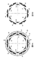
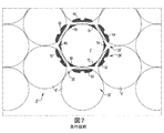
図6A、図6B及び図7に示されているように、同じ問題は、6点せん断機(6-point shear)(54)(図6A)を有する従来の打抜き工具(52)にも関係している。具体的には、6点せん断機(54)は、幾つかの高い部分(60)(62)(64)(66)(68)(70)(72)(74)(76)(78)(80)(82)を有しており、それらは、図7に示すように、ブランク(6')を形成するとき、材料(8')と係合し、押し付けられる。つまり、高い部分(60)(62)(64)(66)(68)(70)は、打抜き工程の間、ウェブ(8')の製品領域(26')に係合し、押し付けられる。一方で、高い部分(72)(74)(76)(78)(80)(82)は、材料(8')のウェブ(28')(例えば、ブランク(6')間の廃棄材料の領域)に係合する。従って、図1A−図4を参照して上述した4点せん断機(4)と同様に、6点せん断機(54)の部分が係合し、そして、それにより、ブランク(6')(図7)を引っ掻き、さもなくば傷付けて(例えば、掻き傷や擦り傷)を付けてしまうことがある。 As shown in FIGS. 6A, 6B, and 7, the same problem is associated with a conventional punching tool (52) having a 6-point shear (54) (FIG. 6A). ing. Specifically, the six-point shearing machine (54) has several high sections (60) (62) (64) (66) (68) (70) (72) (74) (76) (78) ( 80) (82), which engage and press the material (8 ') when forming the blank (6'), as shown in FIG. That is, the high portions (60), (62), (64), (66), (68), and (70) are engaged and pressed against the product area (26 ') of the web (8') during the punching process. On the other hand, the high part (72) (74) (76) (78) (80) (82) is the area of waste material between the web (28 ') of material (8') (e.g. blank (6 ') ). Thus, similar to the four-point shear (4) described above with reference to FIGS. 1A-4, the portion of the six-point shear (54) is engaged and thereby the blank (6 ′) (FIG. 7) may be scratched or otherwise damaged (e.g., scratched or scratched).
従って、カップや容器を作製するためのツーリングアセンブリには改良の余地があり、それと同様に、打抜き工具と関連する方法とにも改良の余地がある。 Accordingly, there is room for improvement in tooling assemblies for making cups and containers, as well as in the methods associated with punching tools.
これら及びその他の要請は、ツーリングアセンブリ、打抜き工具及び関連する方法を対象とする開示された概念の実施形態により達成される。利点の中でも特に、打抜き工具は、ブランク自体と接触して損傷を与えることなく(例えば、これらに限定されないが、引っ掻かれる又は傷付けられることなく)、ブランクを効果的に切り取る。 These and other needs are met by embodiments of the disclosed concept directed to tooling assemblies, punching tools and related methods. Among other advantages, the punching tool effectively cuts the blank without touching and damaging the blank itself (eg, without limitation, without being scratched or scratched).
開示された概念の態様として、打抜き工具は、シート状の材料から複数のブランクを切り取るために提供される。シート状の材料は、ブランクが位置するシート状の材料の領域に対応する製品領域と、材料におけるブランクの間の領域に対応するウェブ領域とを含んでいる。打抜き工具は、第1側部と、前記第1側部の反対側にある第2側部と、外径と、内径とを含むせん断機と、前記せん断機の前記第2側部に配置された複数の接触表面とを具えている。打抜き工具の接触表面は、ウェブのみと係合する。 As an aspect of the disclosed concept, a punching tool is provided for cutting a plurality of blanks from a sheet of material. The sheet-like material includes a product area corresponding to the area of the sheet-like material where the blank is located and a web area corresponding to the area between the blanks in the material. The punching tool is disposed on a first side, a second side opposite to the first side, a shear including an outer diameter and an inner diameter, and the second side of the shear. A plurality of contact surfaces. The contact surface of the punching tool engages only with the web.
開示された概念の他の態様では、ツーリングアセンブリが、プレス用に提供される。プレスは、シート状の材料を受け入れて、シート状の材料に幾つかの機械加工を実行するように構成されている。ツーリングアセンブリは、プレスの第1部分と結合するように構成された第1ツーリングと、第1ツーリングに対向し、プレスの第2部分と結合するように構成された第2ツーリングと、第1ツーリングと結合された打抜き工具とを備えている。第1ツーリングと第2ツーリングは協動して、それらの間にてシート状の材料に係合するように構成されている。打抜き工具は、第1側部と、第1側部の反対側にある第2側部と、外径と、内径とを備えるせん断機と、せん断機の第2側部に配置された複数の接触表面とを備えている。打抜き工具のせん断機は、第2ツーリングの一部分と協動して、材料からブランクを切り取る。材料は、ブランクが位置する材料の領域に対応する製品領域と、材料におけるブランクの間の領域に対応するウェブ領域とを含んでいる。打抜き工具の接触表面は、ウェブのみと係合する。 In another aspect of the disclosed concept, a tooling assembly is provided for the press. The press is configured to accept a sheet of material and perform some machining on the sheet of material. A tooling assembly includes a first tooling configured to couple with a first portion of a press, a second tooling opposed to the first tooling and configured to couple with a second portion of the press, and a first tooling. And a punching tool coupled with the. The first tooling and the second tooling are configured to cooperate to engage the sheet-like material therebetween. The punching tool includes a first side, a second side that is opposite the first side, an outer diameter, an inner diameter, and a plurality of shearing machines disposed on the second side of the shearing machine. A contact surface. The punching tool shearing machine cooperates with a portion of the second tooling to cut a blank from the material. The material includes a product area corresponding to the area of the material where the blank is located and a web area corresponding to the area between the blanks in the material. The contact surface of the punching tool engages only with the web.
開示された概念の更なる態様は、ブランクを形成する方法であって、第1ツーリングと、第1ツーリングに対向配置される第2ツーリングとを含むプレスを設ける工程と、
第1側部と、第1側部とは反対側にある第2側部と、第2側部に配置された複数の接触領域とを備える打抜き工具を、第1ツーリングに結合する工程と、第1ツーリングと前記第2ツーリングの間にシート状の材料を供給する工程と、プレスを作動して、シート状の材料をせん断機と係合させて、材料から複数のブランクを切り取る工程とを含んでいる。シート状の材料は、ブランクが位置する材料の領域に対応する製品領域と、材料におけるブランクの間の領域に対応するウェブ領域とを含んでおり、打抜き工具の接触表面は、ウェブのみと係合する。
A further aspect of the disclosed concept is a method of forming a blank, comprising providing a press including a first tooling and a second tooling disposed opposite the first tooling;
Coupling a punching tool comprising a first side, a second side opposite the first side, and a plurality of contact areas disposed on the second side to the first tooling; Supplying a sheet-like material between the first tooling and the second tooling; and operating a press to engage the sheet-like material with a shearing machine to cut a plurality of blanks from the material. Contains. The sheet-like material includes a product area corresponding to the area of the material where the blank is located and a web area corresponding to the area between the blanks in the material, the contact surface of the punching tool engaging only the web. To do.
開示された概念の完全な理解は、添付の図面と併せて、好ましい実施形態に関する以下の説明を読むことで得られる。
例示の目的として、開示された概念の実施の形態は、シート状の材料(例えば、これに限定されないが、シート材料)からブランクを切り出し(例えば、せん断し)、続いて、ブランクからカップや容器(例えば、これらに限定されないが、飲料/ビール用缶や食料缶)を形成するように構成されているとして説明されているが、それらは様々な目的と用途のために、任意の既知又は適切な材料のブランクを適切に切り出し(せん断)するように実施されることは明らかであろう。 For illustrative purposes, embodiments of the disclosed concepts may be used to cut (e.g., shear) a blank from sheet-like material (e.g., but not limited to, sheet material), and then cup or container from the blank. Although described as being configured to form (e.g., but not limited to, beverage / beer cans or food cans), they may be any known or appropriate for various purposes and applications. It will be apparent that this is done to properly cut (shear) blanks of the correct material.
当然のことながら、添付の図面に示されており、明細書で説明されている具体的な要素は、開示された概念の単なる例示的な実施の形態であって、単なる例示の目的で、非限定な実施例として提示されている。そのため、本明細書で開示されている実施例に関する具体的な寸法、方向及び他の物理的な特徴は、開示された概念の範囲を限定していると考えられるべきではない。 It should be understood that the specific elements illustrated in the accompanying drawings and described in the specification are merely exemplary embodiments of the disclosed concepts and are for illustrative purposes only. It is presented as a limited example. As such, the specific dimensions, orientations, and other physical characteristics associated with the embodiments disclosed herein are not to be considered as limiting the scope of the disclosed concepts.
本明細書で用いられる向きを示す語句、例えば、左、右、前、後、上、下、上側、下側、及びそれらの派生語等は、図面で示された構成要素の向きに関しており、請求の範囲にて明記されていない限り、請求の範囲を限定しない。 Words orientations used in this specification, such as left, right, front, back, top, bottom, top, bottom, and derivatives thereof, relate to the orientation of the components shown in the drawings, The claims are not limited unless explicitly stated in the claims.
本明細書で用いられているように、「ファスナ」や「締結機構(fastening mechanism)」なる用語は、一つの構成部材を、これに限定されないが、ボルトと、ボルトとナット(例えば、これに限定されないが、ロックナット)の組合せと、ボルト、ワッシャー及びナットの組み合わせとを含む適切な任意の接続又は締付機構に言及している。 As used herein, the terms “fastener” and “fastening mechanism” refer to a single component, including, but not limited to, a bolt, a bolt and a nut (for example, Reference is made to any suitable connection or tightening mechanism including, but not limited to, a lock nut combination and a bolt, washer and nut combination.
本明細書で用いられているように、2又は3以上の部品が互いに「結合される」という状態は、その部品が互いに直接的に連結されているか、或いは1又は複数の中間部品を介して連結されることを意味する。 As used herein, a state in which two or more parts are “coupled” to each other means that the parts are directly connected to each other or via one or more intermediate parts. It means to be connected.
本明細書で用いられているように、「数」という用語は、1又はそれより大きい整数(つまり、複数)を意味する。 As used herein, the term “number” means an integer (ie, a plurality) that is one or more.
図8及び図9Aは、プレス(400)(図15)のツーリングアセンブリ(300)(図15)と共に用いられる打抜き工具(102)を示している。本明細書に記載され、説明されている実施例において、打抜き工具(102)は、6点せん断機(104)(即ち、カットエッジ)であるが、開示された概念は、ポイントについて、公知の又は適したその他の任意の数、形状及び/又は配置(例えば、これに限定されないが、4点せん断機(図示せず))を有するせん断機(図示せず)に適用できることは理解できるであろう。 8 and 9A show a punching tool (102) used with the tooling assembly (300) (FIG. 15) of the press (400) (FIG. 15). In the embodiment described and illustrated herein, the punching tool (102) is a six-point shear (104) (ie, a cut edge), but the disclosed concept is known for points. Or any other suitable number, shape and / or arrangement (e.g., but not limited to, a four point shear (not shown)) can be applied to a shear (not shown). Let's go.
例示のせん断機(104)は、対向する第1側部(106)及び第2側部(108)と、外径(110)と、内径(112)とを含む。外径(110)と内径(112)の具体的な大きさは、開示された概念の態様の限定を意味するものではない。しかしながら、当然のことであるが、せん断機(104)の内径(112)は、通常、せん断機(104)によって切り出し(例えば、せん断)されるブランク(6'')(図10)の大きさと同じサイズである。複数の接触表面(118)(120)(122)(124)(126)(128)(6カ所示す)は、せん断機(104)の第2側部(108)に配置されている。接触表面(118)(120)(122)(124)(126)(128)は、高い部分、即ち、せん断機(104)の第2側部(108)から外向きに延出した場所を構成する。本明細書に記載され、説明されている非限定的な実施例において、接触表面(118)(120)(122)(124)(126)(128)は、複数の機械加工された表面(130)(132)(134)(136)(138)(140)を形成するように、せん断機(104)の第2側部(108)を機械加工して形成される。それらの各々は、上述した接触表面(118)(120)(122)(124)(126)(128)の対応するペアの間に配置される。言い換えれば、例えば、これに限定されないが、砥石車(200)(図11及び図12に簡略化された形態が示される)を用いることによって、表面(130)(132)(134)(136)(138)(140)を研磨するか又はさもなくば適切に機械加工することで、せん断機(104)の第2側部(108)から材料が取り除かれ、位置が高い所望の構成の接触領域(118)(120)(122)(124)(126)(128)が形成される。 The exemplary shearing machine (104) includes opposing first and second sides (106), (108), an outer diameter (110), and an inner diameter (112). The specific dimensions of the outer diameter (110) and the inner diameter (112) do not imply a limitation on the aspect of the disclosed concept. However, it will be appreciated that the inner diameter (112) of the shearing machine (104) is usually the size of the blank (6 '') (FIG. 10) cut (eg, sheared) by the shearing machine (104). Same size. A plurality of contact surfaces (118), (120), (122), (124), (126), (128) (six) are disposed on the second side (108) of the shearing machine (104). The contact surface (118) (120) (122) (124) (126) (128) constitutes a high part, that is, a place extending outward from the second side (108) of the shearing machine (104) To do. In the non-limiting examples described and illustrated herein, the contact surface (118) (120) (122) (124) (126) (128) comprises a plurality of machined surfaces (130 ) (132) (134) (136) (138) (140) is formed by machining the second side (108) of the shearing machine (104). Each of them is disposed between the corresponding pair of contact surfaces (118) (120) (122) (124) (126) (128) described above. In other words, for example, but not limited to, surfaces (130) (132) (134) (136) by using a grinding wheel (200) (simplified form shown in FIGS. 11 and 12). (138) (140) is polished or otherwise properly machined to remove material from the second side (108) of the shearing machine (104) and to provide a high contact area of the desired configuration (118) (120) (122) (124) (126) (128) are formed.
従って、開示された概念は、打抜き工具(102)の選択的な機械加工を含んでおり、せん断機(104)が、ブランク(6'')(図10)が形成される材料(8'')(図10)と係合するあり方を制御することは明らかである。材料(8'')(図10)に対するせん断機(104)(図8、図9A、図11、図12、図14及び図15)の接触領域(118)(120)(122)(124)(126)(128)(例えば、接触のパターン及び/又は位置)は、図9B及び図10に最もよく示されている。図10を参照すると、打抜き工程の結果として、材料(8'')は、ブランク(6'')が配置される材料(8'')の領域に対応している製品領域(26'')と、そのようなブランク(6'')の間の廃棄材料領域に対応しているウェブ、即ちスケルトン(28'')とを含むことは明らかである。開示された打抜き工具(102)、特に、せん断機(104)の接触領域(118)(120)(122)(124)(126)(128)は、材料(8'')のウェブ(28'')のみと係合する。この方法において、開示された打抜き工具(102)は、有利な点として、ブランク(6'')との接触を避けており、それによって、ブランク(6'')を引っ掻き、さもなくば傷付けて(例えば、これらに限定されないが、掻き傷や擦り傷)、又は、損傷を与えることを避けている。つまり、従来の打抜き工具(例えば、図1A及び図2の4点せん断機(4)参照。さらに、図6Aの6点せん断機(54)参照)とは異なり、開示されたせん断機(104)は、材料(8'')の製品領域(26'')と接触しない。それにより、ブランク(6'')は、接触することなく又は損傷を受けることなく(例えば、限定されないが、引っ掻かれる又は傷付けられることなく)、効果的にせん断される。従って、従来技術に関した既知の問題が、例えば、カップ(例えば、図5の傷ついたカップを参照)に傷を付けて、最終産物(例えば、これに限定されないが、缶ボディ(図示せず))を傷付ける恐れがある打抜き工程の間に、せん断機(図1A及び図2のせん断機参照。また図6Aのせん断機(54)参照)又はストックプレート(例えば、図15及び図16のストックプレート(306))によってブランク(図3及び図4のブランク(6)参照。図7のブランク(6')参照)に与えられる損傷が無くなる。 Thus, the disclosed concept involves the selective machining of the punching tool (102) so that the shearing machine (104) is the material (8 '') from which the blank (6 '') (FIG. 10) is formed. It is clear to control the manner in which the) (FIG. 10) is engaged. Contact area (118) (120) (122) (124) of shearing machine (104) (FIGS. 8, 9A, 11, 12, 14 and 15) against material (8 '') (FIG. 10) (126) (128) (eg, contact pattern and / or location) is best shown in FIGS. 9B and 10. Referring to FIG. 10, as a result of the punching process, the material (8 '') is a product area (26 '') corresponding to the area of the material (8 '') where the blank (6 '') is placed. And a web corresponding to the waste material region between such blanks (6 ″), ie a skeleton (28 ″). The disclosed punching tool (102), in particular the contact area (118) (120) (122) (124) (126) (128) of the shearing machine (104), is a web (28 ') of the material (8' '). Engage only with '). In this way, the disclosed punching tool (102) advantageously avoids contact with the blank (6 ''), thereby scratching or otherwise scratching the blank (6 ''). (For example, but not limited to, scratches and abrasions) or avoiding damage. In other words, unlike the conventional punching tool (see, for example, the four-point shearing machine (4) in FIGS. 1A and 2 and the six-point shearing machine (54) in FIG. 6A), the disclosed shearing machine (104). Does not contact the product area (26 ″) of the material (8 ″). Thereby, the blank (6 ″) is effectively sheared without contact or damage (eg, without limitation, without being scratched or damaged). Thus, a known problem with the prior art is, for example, scratching the cup (see, for example, the damaged cup of FIG. 5), resulting in a final product (eg, but not limited to a can body (not shown)). ) During the punching process that may damage the shearing machine (see shearing machine in FIGS. 1A and 2; see also shearing machine (54) in FIG. 6A) or stock plate (eg the stocking plate in FIGS. 15 and 16). (306)) eliminates damage to the blank (see blank (6) in FIGS. 3 and 4; see blank (6 ′) in FIG. 7)).
図10に示されるように、せん断機(104)の各接触領域(118)(120)(122)(124)(126)(128)の形状は、材料(8'')のウェブ又はスケルトン(28'')とほぼ似たように形作られるのが好ましい。具体的には、図9B、図10及び図11に示される非限定的な実施例では、例えば、接触領域(118)は、3つの弓状側部(142)(144)(146)を含む。第1弓状側部(142)は、図11に示すように、せん断機(104)の内径(112)を規定する内縁にほぼ揃っている。第2弓状側部(144)は、それに対応しており、対向するウェブ(28'')の弓状領域とほぼ同様に形作られて、ほぼ平行になっている。当該弓状領域は、第2弓状側部(144)に隣接するブランク(6'')を取り除くことによって規定される。同様に、第3弓状側部(146)は、それに対応しており、対向するウェブ(28'')の弓状領域とほぼ同様に形作られて、ほぼ平行になっている。当該弓状領域は、第3弓状側部(146)に隣接するブランク(6'')を取り除くことによって規定される。言い換えれば、本明細書で示され、説明されている実施例では、接触領域(118)の形状は、概ね、それに対応する材料(8'')のウェブ(28'')の部分の略三角形の形状に対応しており、ここで、各弓状側部(142)(144)(146)は、図示されているように窪んでいる。しかしながら、接触領域について、公知又は適切なその他の任意の数、形や構成(図示せず)が用いられて、開示された概念に従って、材料(8'')のウェブ(28'')のみに係合するようにできることは理解できるであろう。 As shown in FIG. 10, the shape of each contact area (118) (120) (122) (124) (126) (128) of the shearing machine (104) is a web or skeleton of material (8 '') ( It is preferably shaped in a manner similar to 28 ″). Specifically, in the non-limiting example shown in FIGS. 9B, 10 and 11, for example, the contact region (118) includes three arcuate sides (142) (144) (146). . As shown in FIG. 11, the first arcuate side (142) is substantially aligned with the inner edge that defines the inner diameter (112) of the shearing machine (104). The second arcuate side (144) is correspondingly shaped and substantially parallel to the arcuate region of the opposing web (28 ″). The arcuate region is defined by removing a blank (6 ″) adjacent to the second arcuate side (144). Similarly, the third arcuate side (146) is correspondingly shaped and substantially parallel to the arcuate region of the opposing web (28 ″). The arcuate region is defined by removing the blank (6 ″) adjacent to the third arcuate side (146). In other words, in the embodiment shown and described herein, the shape of the contact region (118) is generally approximately triangular in the portion of the web (28 '') of the corresponding material (8 ''). Where each arcuate side (142) (144) (146) is recessed as shown. However, any other number, shape or configuration (not shown) known or appropriate for the contact area may be used, in accordance with the disclosed concept, only on the web (28 '') of the material (8 ''). It will be understood that they can be engaged.
図11及び図12は、砥石車(200)(簡略化した形態で点線で示す。また図12においては、代わりに水平方向で示している)が、表面(130)を機械加工し(例えば、これに限定されなが、研削加工し)、既に説明したように、接触領域(118)(128)間にて、せん断機(104)の第2側部(108)から材料を取り除くことによって、位置が高い所望の接触表面(118)(128)(図11)を形成する模様を示している。図12及び図14に示すように、接触領域の間にある機械加工された表面、例えば、接触領域(118)(128)の間にある表面(130)は、予め定められた所定のせん断角(shear angle)(190)を有するように機械加工されるのが好ましい(図14の拡大図に最もよく示されている)。図14のせん断角(190)と図13の従来技術の打抜き工具(2)のせん断角(90)とを比較すると、機械加工された表面(130)は、せん断角(190)で続いている、即ち当該角度で配置されている。一方、図13の従来技術のせん断機(4)は、機械加工された同様な表面を有しておらず、そして、せん断角(90)で続いておらず、むしろ、更なる高い部分、つまり接触する領域を含んでいる(例えば、図1A及び図2のせん断機(4)の高い部分(10)参照)ことが理解できるであろう。図14の実施例において、せん断角(190)は、図13の従来技術のせん断機のせん断角(90)よりも大きいが、せん断角(190)の具体的な大きさは、開示された概念の態様を限定することを意図するものではないことは明らかである。例えば、これに限定されないが、開示された概念の一つの非限定的な実施形態では、せん断角(190)は、略30度までにされてよい。 FIGS. 11 and 12 illustrate a grinding wheel (200) (shown in dotted form in a simplified form, and in FIG. 12 instead shown in a horizontal direction) where the surface (130) is machined (e.g., (But not limited to), and as previously described, by removing material from the second side (108) of the shearing machine (104) between the contact areas (118) (128), It shows a pattern that forms the desired contact surface (118) (128) (FIG. 11) in high position. As shown in FIGS. 12 and 14, a machined surface between the contact areas, eg, a surface (130) between the contact areas (118), (128), has a predetermined predetermined shear angle. Preferably machined to have a (shear angle) (190) (best shown in the enlarged view of FIG. 14). Comparing the shear angle (190) of FIG. 14 with the shear angle (90) of the prior art punching tool (2) of FIG. 13, the machined surface (130) continues at the shear angle (190). That is, they are arranged at the angle. On the other hand, the prior art shear machine (4) of FIG. 13 does not have a similar machined surface and does not continue at the shear angle (90), but rather a higher part, It will be appreciated that it includes a contact area (see, for example, the high portion (10) of the shear (4) in FIGS. 1A and 2). In the example of FIG. 14, the shear angle (190) is greater than the shear angle (90) of the prior art shear machine of FIG. 13, although the specific magnitude of the shear angle (190) is the disclosed concept. It is clear that the embodiments are not intended to be limited. For example, but not limited to, in one non-limiting embodiment of the disclosed concept, the shear angle (190) may be up to approximately 30 degrees.
図15及び図16は、開示された打抜き工具(102)が、開示された概念の非限定的な実施形態に従って、プレス(400)のツーリングアセンブリ(300)(断面図において部分的に示されている)で用いられる模様を示している。ツーリングアセンブリ(300)は、第1ツーリング(例えば、番号(302)で全般的に示されている、図15及び図16の図における上部ツーリング)と、上部ツーリングから反対側に配置されている第2ツーリング(例えば、番号(304)で全般的に示されている、図15及び図16の図における下側ツーリング)を含む。上述したシート状の材料(8'')(図15及び図16にて、簡略された形態で一点鎖線で示されている)は、プレス(400)にて、上部ツーリング(302)と下部ツーリング(304)との間に供給される。せん断機(104)は、既知又は適切な任意の締結機構を用いた上部ツーリング(302)に結合される。例えば、これに限定されないが、本明細書に示され、記載されているせん断機(104)は、上部ツーリング(302)に打抜き工具(102)を固定するための幾つかのボルト孔(114)(116)(図9A、図11及び図12、図の簡略化のために図8には示さず)を備えている。 15 and 16 show that the disclosed punching tool (102) is shown in part in a tooling assembly (300) of a press (400) (partially shown in a cross-sectional view) according to a non-limiting embodiment of the disclosed concept. The pattern used in The tooling assembly (300) includes a first tooling (eg, the upper tooling generally indicated by the number (302) in FIGS. 15 and 16) and a first tooling disposed opposite the upper tooling. 2 tooling (eg, lower tooling in the views of FIGS. 15 and 16, generally indicated by the number (304)). The above-mentioned sheet-like material (8 ″) (shown in a simplified form in FIG. 15 and FIG. 16 by a one-dot chain line) is formed by pressing (400) with an upper tooling (302) and a lower tooling. (304). The shear (104) is coupled to the upper tooling (302) using any known or appropriate fastening mechanism. For example, but not limited to, the shearing machine (104) shown and described herein has several bolt holes (114) for securing the punching tool (102) to the upper tooling (302). (116) (FIG. 9A, FIG. 11 and FIG. 12, not shown in FIG. 8 for simplicity of illustration).
動作中、シート状の材料(8'')は、例えば、ロール(図示せず)又はシート(図示せず)のスタックからプレス(400)に供給される。プレス(400)が作動して、上部ツーリング(302)、特にせん断機(104)を、下部ツーリング(302)、特にストックプレート(306)に向けて進ませて、材料(8'')が係合して、切り取られて、上述したブランク(6'')が形成される(図10)。ストックプレート(306)は、材料(8'')がツーリングアセンブリ(300)(例えば、これに限定されないが、ダイセット)を通るように供給される際に、それを支持する。この打抜き工程の間、上述したせん断機(104)の接触領域(118)(120)(122)(124)(126)(128)(図9A−図11に全て示されている)は、図10に示すように、且つ、明細書で既に記載したように、材料(8'')のウェブ又はスケルトン(28'')のみと接触する。ストックプレート(306)は、復帰するように構成されており(例えば、これらに限定されないが、バネ、空気圧、又は油圧により支持されている)、せん断機(104)が、材料(8'')がそれらの間に挟まれた状態で、それを押圧すると、下向きに動くことができる。打抜き工程の後、ストックプレート(306)が、材料(8'')のウェブ又はスケルトン(28'')(図10)を持ち上げるのを補助する一方で、ブランク(6'')(図10)は、カップ(図示せず、図5のカップ(30)を参照)を成形するために、ブランク引抜きダイ(308)を介して下方に引かれる。 In operation, the sheet-like material (8 ″) is supplied to the press (400) from, for example, a roll (not shown) or a stack of sheets (not shown). The press (400) is activated and the upper tooling (302), in particular the shearing machine (104), is advanced towards the lower tooling (302), in particular the stock plate (306), and the material (8 '') is engaged. Together, they are cut to form the blank (6 ″) described above (FIG. 10). The stock plate (306) supports the material (8 '') as it is fed through the tooling assembly (300) (eg, but not limited to a die set). During this punching process, the contact areas (118) (120) (122) (124) (126) (128) of the shearing machine (104) described above (all shown in FIGS. 9A-11) are shown in FIG. As shown in FIG. 10 and as already described in the specification, only the web of material (8 ″) or skeleton (28 ″) is contacted. The stock plate (306) is configured to return (e.g., but is not limited to being supported by a spring, air pressure, or hydraulic pressure), and the shearing machine (104) is made of material (8 ''). When it is sandwiched between them, it can be moved downward. After punching punching step, stock plate (306) to the material (8 '') web or skeleton (28 ''), while to assist in lifting the (FIG. 10), the blank (6 '') (Fig. 10 ) Is drawn down through a blank drawing die (308) to form a cup (not shown, see cup (30) in FIG. 5).
開示された打抜き工具(102)の更なる利点が、工具の寿命を長くすることは理解できるであろう。即ち、動作中、先行技術のせん断機(例えば、図1A及び図2のせん断機参照)は、比較的速い速度と大きなトン数で、ストックプレート(306)に(それらの間に材料(8'')を挟んだ状態で)衝撃を与えるので、せん断機(4)(図1A及び図2)の幾つかの高い部分(例えば、図1A−図3の高い部分(18)(20)(22)(24))に対向したストックプレート(306)の領域は、擦り減ってしまう。一方、開示されたせん断機(104)は、より少数の接触領域(118)(120)(122)(124)(126)(128)(6点が示されている)を用いており、各接触領域(118)(120)(122)(124)(126)(128)は、比較的大きな表面領域を有している(例えば、図1A及び図2のせん断機(4)の高い部分(18)(20)(22)(24)の比較的小さい表面領域と、開示されたせん断機(104)(図8、図9A及び図11)の高い部分(118)(120)(122)(124)(126)(128)の比較的大きい表面領域とを比較する)。表面領域を大きくするように改良された設計は、従来の設計よりも、せん断機(104)からの衝撃荷重をより広く、より均等に分配できる点で有利である。これにより、ストックプレート(306)に起こる摩耗が少なくなる。 It will be appreciated that a further advantage of the disclosed punching tool (102) increases tool life. That is, during operation, prior art shears (see, for example, the shears of FIGS. 1A and 2) are applied to the stock plate (306) (with a material (8 ′ between them) at a relatively high speed and large tonnage. ') With some impact on it, so that some high parts of the shearing machine (4) (FIGS. 1A and 2) (eg, high parts (18), (20), (22) in FIGS. 1A-3) ) (24)), the area of the stock plate (306) is worn away. On the other hand, the disclosed shearing machine (104) uses a smaller number of contact areas (118) (120) (122) (124) (126) (128) (six points shown), The contact areas (118) (120) (122) (124) (126) (128) have a relatively large surface area (for example, the high part of the shearing machine (4) of FIGS. 1A and 2). 18) (20) (22) (24) relatively small surface area and the high portion (118) (120) (122) (12) of the disclosed shearing machine (104) (FIGS. 8, 9A and 11). 124) (126) (128) compared to the relatively large surface area). The improved design to increase the surface area is advantageous in that the impact load from the shearing machine (104) can be distributed more broadly and more evenly than the conventional design. This reduces the wear that occurs on the stock plate (306).
更に摩耗を減少させるために、打抜き工具(102)はさらに、例えば、これに限定されないが、図16に記載されているような、せん断機(104)に挿入されるカーバイドリング(310)を随意に含んでよい。即ち、カーバイドは非常に硬いので、カーバイドリング(310)が用いられると、打抜き工具(102)の切出し又は打抜きエッジは長持ちする。カーバイドリング(310)は、打抜き工具(102)の形状に影響しないのが好ましいことは理解できるであろう。 To further reduce wear, the punching tool (102) further optionally includes a carbide ring (310) inserted into the shearing machine (104), such as, but not limited to, FIG. May be included. That is, since the carbide is very hard, when the carbide ring (310) is used, the cutting or punching edge of the punching tool (102) will last longer. It will be appreciated that the carbide ring (310) preferably does not affect the shape of the punch tool (102).
以上のように、開示された打抜き工具(102)は、各ブランク(6'')(図10)のどの部分とも係合せずに、ブランク(6'')(図10)を効果的に切り出し(例えば、せん断)するせん断機(104)を備える。従って、打抜き工程の間のブランク(6'')の損傷(例えば、これに限定されないが、引掻き又は他の傷)が解消され、それによって、従来技術の打抜き工具(図1A及び図2の打抜き工具(2)参照、図6Aの打抜き工具(52)参照)に関連して知られている、カップ(図5の傷の付いたカップ(30)参照)又はブランク(6'')から形成された最終製品(例えば、これらに限定されないが、容器、ビール/飲料缶や食料缶(図示せず))が接触欠損する可能性を排除できる。 As described above, the disclosed punching tool (102) effectively cuts out the blank (6 '') (FIG. 10) without engaging any part of each blank (6 '') (FIG. 10). A shearing machine (104) is provided (for example, shearing). Accordingly, damage to the blank (6 ″) during the punching process (eg, but not limited to scratching or other flaws) is eliminated, thereby reducing the prior art punching tool (the punching of FIGS. 1A and 2). Formed from a cup (see scratched cup (30) in FIG. 5) or blank (6 ″), known in relation to tool (2), see punching tool (52) in FIG. 6A) In addition, the possibility of contact failure of the final product (eg, but not limited to containers, beer / beverage cans or food cans (not shown)) can be eliminated.
開示された概念の具体的な実施形態の詳細を説明したが、当該技術分野の通常の知識を有する者には、これらの詳細について様々な変更及び置換が、開示された技術を踏まえて行われてよいことを理解するであろう。従って、開示された具体的な構成は、あくまで説明の目的のものであって、特許請求の範囲とその任意のおよそ全ての均等物とに認められる本発明の技術的範囲を制限するものではない。 While specific embodiments of the disclosed concepts have been described in detail, those skilled in the art may make various changes and substitutions to these details in light of the disclosed technology. You will understand. Accordingly, the specific configuration disclosed is for illustrative purposes only and is not intended to limit the scope of the present invention which is found in the claims and any and all equivalents thereof. .
Claims (14)
前記シート状の材料は、前記複数のブランクが位置する前記シート状の材料の領域に対応する製品領域と、前記シート状の材料における前記複数のブランクの間の領域に対応するウェブ領域とを含んでおり、
前記ウェブ領域は、複数の略三角形状の領域を含んでおり、前記複数の略三角形状の領域の各々は、前記複数のブランクの中の3つのブランクで規定されており、
前記打抜き工具は、
第1側部と、前記第1側部の反対側にある第2側部と、外径と、内径とを含むせん断機と、
前記せん断機の前記第2側部に配置された複数の接触表面とを備えており、
前記複数の接触表面の各々は、前記複数の略三角形状の領域における特定の一つの略三角形状の領域のみと係合するように構成されている打抜き工具。 A punching tool for cutting a plurality of blanks from a sheet-like material,
The sheet-like material includes a product region corresponding to a region of the sheet-like material where the plurality of blanks are located, and a web region corresponding to a region between the plurality of blanks in the sheet-like material. And
The web region includes a plurality of substantially triangular regions, and each of the plurality of substantially triangular regions is defined by three blanks among the plurality of blanks,
The punching tool is
A shearing machine including a first side, a second side opposite to the first side, an outer diameter, and an inner diameter;
A plurality of contact surfaces disposed on the second side of the shearing machine,
Each of the plurality of contact surfaces is a punching tool configured to engage with only one specific substantially triangular region in the plurality of substantially triangular regions .
前記接触表面は、3つの弓状側部を含み、
第1弓状側部は、前記内縁にほぼ揃っており、
第2弓状側部は、前記第2弓状側部に対向する前記ウェブ領域の部分とほぼ似たように形作られており、前記ウェブ領域の部分は、前記複数のブランクの中の一つを取り除くことによって規定され、
第3弓状側部は、前記第3弓状側部に対向する前記ウェブ領域の別の部分とほぼ似たように形作られており、前記ウェブ領域の別の部分は、前記複数のブランクの中の別の一つを取り除くことによって規定されている、請求項2に記載の打抜き工具。 The inner diameter is defined by the inner edge of the shearing machine;
The contact surface includes three arcuate sides;
The first arcuate side is substantially aligned with the inner edge;
The second arcuate side portion is shaped to be substantially similar to the portion of the web region facing the second arcuate side portion, wherein the web region portion is one of the plurality of blanks. Stipulated by removing
Third arcuate sides, said opposite said third arcuate sides are shaped as substantially similar to another portion of the web region, another portion of the web region, the plurality of blanks 3. A punching tool according to claim 2, defined by removing another one therein.
前記機械加工された複数の表面の各々は、前記複数の接触表面が、前記せん断機の前記第2側部に複数の高い部分を備えるように、前記複数の接触表面の一対の間に配置された窪み領域である、
請求項1に記載の打抜き工具。 The plurality of contact surfaces are defined by a plurality of machined surfaces;
Each of the plurality of machined surfaces is disposed between a pair of the plurality of contact surfaces such that the plurality of contact surfaces comprise a plurality of elevated portions on the second side of the shearing machine. A recessed area,
The punching tool according to claim 1.
前記機械加工された複数の表面は、前記複数の高い部分の前記平面に対して、0度から30度の間のせん断角で配置されている、請求項4に記載の打抜き工具。 The plurality of high portions are arranged on a plane;
The punching tool according to claim 4, wherein the machined surfaces are arranged at a shear angle between 0 degrees and 30 degrees with respect to the flat surface of the plurality of high portions.
前記プレスは、シート状の材料を受け入れて、前記シート状の材料に幾つかの機械加工を実行するように構成されており、
前記ツーリングアセンブリは、
前記プレスの第1部分と結合するように構成された第1ツーリングと、
前記第1ツーリングに対向し、前記プレスの第2部分と結合するように構成された第2ツーリングと、
前記第1ツーリングと結合された、請求項1乃至6の何れかに記載の打抜き工具とを備えており、
前記第1ツーリングと前記第2ツーリングは協動して、それらの間にて前記シート状の材料に係合するように構成されている、ツーリングアセンブリ。 A tooling assembly for pressing,
The press is configured to accept a sheet of material and perform some machining on the sheet of material;
The tooling assembly is
A first tooling configured to couple with a first portion of the press;
A second tooling configured to face the first tooling and to couple with a second portion of the press;
A punching tool according to any one of claims 1 to 6, which is coupled to the first tooling.
A tooling assembly, wherein the first tooling and the second tooling are configured to cooperate to engage the sheet-like material therebetween.
前記複数のファスナの各々は、それに対応する前記複数の孔の一つを通って延びて、前記第1ツーリングに前記せん断機を固定する、請求項7に記載のツーリングアセンブリ。 The punching tool further comprises a plurality of holes and a plurality of fasteners in the shearing machine,
The tooling assembly according to claim 7, wherein each of the plurality of fasteners extends through one of the corresponding plurality of holes to secure the shear to the first tooling.
前記ストックプレートは、前記せん断機が前記シート状の材料を切り取って、前記複数のブランクを作製する際に、前記シート状の材料を支持するように構成されている、請求項7に記載のツーリングアセンブリ。 The second tooling comprises a stock plate;
The tooling according to claim 7, wherein the stock plate is configured to support the sheet-like material when the shearing machine cuts the sheet-like material to produce the plurality of blanks. assembly.
前記ストックプレートは、前記せん断機が、対応する前記複数のブランクの一つを切り取った後に上向きに動いて、前記シート状の材料の前記ウェブを持ち上げるように構成されている、請求項9に記載のツーリングアセンブリ。 The stock plate is configured to move downward when the shearing machine presses the stock plate with the sheet-like material sandwiched therebetween,
The stock plate, the shearing machine, upwardly moving after taking off one of the corresponding plurality of blanks, and is configured to lift the web of the sheet material, to claim 9 Tooling assembly as described.
前記カーバイドリングは、前記せん断機の前記第2側部にて前記内径の周りに配置され、
前記カーバイドリングは、前記打抜き工具の打抜き又は切出しエッジを備えている、請求項7に記載のツーリングアセンブリ。 The punching tool includes a carbide ring,
The carbide ring is disposed around the inner diameter at the second side of the shearing machine;
8. A tooling assembly according to claim 7, wherein the carbide ring comprises a punching or cutting edge of the punching tool.
前記方法は、
第1ツーリングと、前記第1ツーリングに対向配置される第2ツーリングとを含むプレスを設ける工程と、
請求項1乃至6の何れかに記載の打抜き工具を設ける工程と、
前記打抜き工具を、前記第1ツーリングに結合する工程と、
前記第1ツーリングと前記第2ツーリングの間にシート状の材料を供給する工程と、
前記プレスを作動して、前記シート状の材料を前記せん断機と係合させて、前記シート状の材料から複数のブランクを切り取る工程とを含んでおり、
前記シート状の材料は、前記複数のブランクが位置する前記シート状の材料の領域に対応する製品領域と、前記シート状の材料における前記複数のブランクの間の領域に対応するウェブ領域とを含んでおり、
前記打抜き工具の前記複数の接触表面は、前記ウェブのみと係合する方法。 A method of forming a blank,
The method
Providing a press including a first tooling and a second tooling disposed opposite to the first tooling;
Providing the punching tool according to any one of claims 1 to 6,
Coupling the punching tool to the first tooling;
Supplying a sheet-like material between the first tooling and the second tooling;
Actuating the press to engage the sheet-like material with the shearing machine and cutting a plurality of blanks from the sheet-like material,
The sheet-like material includes a product region corresponding to a region of the sheet-like material where the plurality of blanks are located, and a web region corresponding to a region between the plurality of blanks in the sheet-like material. And
The plurality of contact surfaces of the punching tool engage only with the web.
前記せん断機が前記シート状の材料を切り取って、前記複数のブランクを作製する際に、前記ストックプレートと前記せん断機との間にて、前記ストックプレート上で前記シート状の材料を支持する工程を更に含む、
請求項12に記載の方法。 The second tooling comprises a stock plate;
A step of supporting the sheet-like material on the stock plate between the stock plate and the shearing machine when the shearing machine cuts the sheet-like material to produce the plurality of blanks. Further including
The method of claim 12.
前記せん断機が、対応する前記複数のブランクの一つを切り取った後に、前記ストックプレートを上向きに動かして、前記シート状の材料の前記ウェブを持ち上げて、前記対応する前記複数のブランクの一つを取り去る工程とを更に含む、請求項13に記載の方法。 Turning the stock plate downward, the shearing machine pressing the stock plate with the sheet-like material sandwiched between them,
The shearing machine, after taking off one of the corresponding plurality of blanks, the stock plate upwardly moves to lift the web of said sheet material, said plurality of blanks the corresponding single 14. The method of claim 13, further comprising the step of removing one.
Applications Claiming Priority (3)
| Application Number | Priority Date | Filing Date | Title |
|---|---|---|---|
| US31231610P | 2010-03-10 | 2010-03-10 | |
| US61/312,316 | 2010-03-10 | ||
| PCT/US2011/026438 WO2011112376A1 (en) | 2010-03-10 | 2011-02-28 | Tooling assembly, blanking tool therefor and associated method |
Publications (3)
| Publication Number | Publication Date |
|---|---|
| JP2013522044A JP2013522044A (en) | 2013-06-13 |
| JP2013522044A5 JP2013522044A5 (en) | 2014-01-09 |
| JP5792751B2 true JP5792751B2 (en) | 2015-10-14 |
Family
ID=44558684
Family Applications (1)
| Application Number | Title | Priority Date | Filing Date |
|---|---|---|---|
| JP2012557078A Active JP5792751B2 (en) | 2010-03-10 | 2011-02-28 | Tooling assembly, punching tool for tooling assembly, and related method |
Country Status (5)
| Country | Link |
|---|---|
| US (2) | US20110219926A1 (en) |
| EP (1) | EP2544837B1 (en) |
| JP (1) | JP5792751B2 (en) |
| CN (1) | CN102791398B (en) |
| WO (1) | WO2011112376A1 (en) |
Families Citing this family (2)
| Publication number | Priority date | Publication date | Assignee | Title |
|---|---|---|---|---|
| CN112372929B (en) * | 2020-10-20 | 2023-12-22 | 浙江致一智能机器人有限公司 | Shearing mechanism for cup cover assembly |
| CN112571515A (en) * | 2020-11-16 | 2021-03-30 | 北京航星机器制造有限公司 | Blanking equipment |
Family Cites Families (78)
| Publication number | Priority date | Publication date | Assignee | Title |
|---|---|---|---|---|
| US1431541A (en) * | 1922-10-10 | Machine for cutting bisks ebom sheet material | ||
| US384532A (en) * | 1888-06-12 | Punch | ||
| US155098A (en) * | 1874-09-15 | Improvement in presses for making tin-can tops | ||
| US2735489A (en) * | 1956-02-21 | fowler | ||
| US1375305A (en) * | 1921-04-19 | Battery-electrodes | ||
| US110396A (en) | 1870-12-20 | Improvement in vehicles | ||
| US353439A (en) * | 1886-11-30 | Half to archibald w | ||
| US1103966A (en) * | 1913-06-11 | 1914-07-21 | Emil F Holinger | Manufacturing seamless tubes. |
| US1202546A (en) * | 1914-07-03 | 1916-10-24 | Mcdonald Machine Co | Process for forming scroll-edge metal blanks. |
| US1369234A (en) * | 1920-01-12 | 1921-02-22 | Theodore J Freund | Punch |
| US1621811A (en) * | 1922-08-24 | 1927-03-22 | Otis K Richard | Punch and die retainer |
| US1817223A (en) * | 1928-01-25 | 1931-08-04 | Greenlee Bros & Co | Metal punch |
| US2086435A (en) * | 1936-05-12 | 1937-07-06 | Rapp Alphonse | Washer cutting tool |
| US2096778A (en) * | 1936-10-19 | 1937-10-26 | Azer Albert | Punch |
| US2545237A (en) * | 1946-01-16 | 1951-03-13 | Maby Per Gunnar | Punching tool |
| US2928451A (en) * | 1955-02-07 | 1960-03-15 | Wales Strippit Corp | Self contained perforating and countersinking unit |
| US3060992A (en) * | 1960-01-11 | 1962-10-30 | Hopp | Means and method for forming non-planar articles |
| US3263465A (en) * | 1961-12-14 | 1966-08-02 | Arthur L Way | Apparatus for and method of severing and sealing hollow conduit |
| US3252315A (en) * | 1962-03-30 | 1966-05-24 | Lyon Inc | Apparatus for manufacturing wheel covers |
| US3319452A (en) * | 1963-10-07 | 1967-05-16 | Rohr Corp | Corrugation punch press |
| US3496753A (en) * | 1966-10-03 | 1970-02-24 | North American Rockwell | Method of making wheel trim or covers |
| US3606565A (en) * | 1969-06-26 | 1971-09-20 | Continental Ind Inc | Self-punching t fitting |
| US3683499A (en) * | 1970-08-07 | 1972-08-15 | Makrite Inc | Unitary piercing punch device |
| US3656394A (en) * | 1970-08-10 | 1972-04-18 | Tally Corp | Punch configuration |
| JPS5251346Y2 (en) * | 1973-01-25 | 1977-11-21 | ||
| US3790876A (en) | 1973-02-15 | 1974-02-05 | Rockwell International Corp | Paper cutting machine |
| US3996832A (en) * | 1975-04-10 | 1976-12-14 | Standard Oil Company (Indiana) | Punch for producing holes in foamed thermoplastic containers |
| US4002092A (en) * | 1975-06-11 | 1977-01-11 | B & M Die Co., Inc. | Compound angle cutting edge and method of using same |
| JPS5653827A (en) * | 1979-10-08 | 1981-05-13 | Honda Eng Kk | Extracting method of approximately circular blank material |
| JPS56134026A (en) * | 1980-03-25 | 1981-10-20 | Tsubakimoto Chain Co | Blanking method |
| US4277891A (en) * | 1980-06-13 | 1981-07-14 | American Optical Corporation | Lens tape cutter |
| US4403417A (en) * | 1982-06-04 | 1983-09-13 | Wilson Stephen K | Draw punch |
| CA1228822A (en) * | 1982-09-29 | 1987-11-03 | Sam C. Pulciani | Container end wall construction |
| US4846033A (en) * | 1985-07-01 | 1989-07-11 | Km-Engineering Ag | Apparatus for making blanks and strips of blanks |
| US4880131A (en) * | 1987-11-13 | 1989-11-14 | Van Dorn Company | Ringless paint container |
| US5024077A (en) * | 1988-01-11 | 1991-06-18 | Redicon Corporation | Method for forming container with profiled bottom |
| US4899447A (en) * | 1988-01-22 | 1990-02-13 | Greenlee Textron Inc. | Panel punch |
| JPH01284433A (en) * | 1988-05-10 | 1989-11-15 | Mitsubishi Electric Corp | Press die |
| US5056392A (en) * | 1988-08-19 | 1991-10-15 | Mate Punch & Die Co. | Punch assembly |
| US4977772A (en) * | 1988-09-02 | 1990-12-18 | Redicon Corporation | Method and apparatus for forming reforming and curling shells in a single press |
| ES2042037T3 (en) * | 1988-10-05 | 1993-12-01 | Sollac | PROCEDURE AND DEVICE FOR CONFORMING A PIECE OF SHEET, ESPECIALLY TO PERFORM A CATHODIC TUBE SCREEN OBTAINED ACCORDING TO THIS PROCEDURE. |
| US5052258A (en) * | 1989-03-16 | 1991-10-01 | Hunter Theodore K | Cutter |
| GB8917049D0 (en) * | 1989-07-26 | 1989-09-13 | Metal Box Plc | An apparatus for,and a method of,cutting a blank |
| JPH0757390B2 (en) * | 1989-11-13 | 1995-06-21 | 東洋製罐株式会社 | Redrawing method |
| US5029392A (en) * | 1990-08-08 | 1991-07-09 | Ideal Industries, Inc. | Two point punch |
| US5235881A (en) * | 1991-04-26 | 1993-08-17 | Toyota Jidosha Kabushiki Kaisha | Piercing die whose punch has different amounts of chamfer at different outer peripheral edge portions |
| US5604044A (en) | 1992-12-28 | 1997-02-18 | Mccabe; Charles J. | Blanks for sheet material forming process |
| US5638717A (en) * | 1993-03-12 | 1997-06-17 | Stodd; Ralph P. | Tooling apparatus for high speed production of drawn metal cup-like articles |
| US5442947A (en) * | 1993-03-12 | 1995-08-22 | Stodd; Ralph P. | Tooling apparatus and method for high speed production of drawn metal cup-like articles |
| US5802907A (en) * | 1993-03-12 | 1998-09-08 | Stodd; Ralph P. | Tooling apparatus and method for high speed production of drawn metal cup-like articles |
| US5394727A (en) * | 1993-08-18 | 1995-03-07 | Aluminum Company Of America | Method of forming a metal container body |
| US5423240A (en) * | 1993-11-18 | 1995-06-13 | Detorre; Robert P. | Side-crowned carbide cutting blades and cutting devices |
| GB9417299D0 (en) * | 1994-08-27 | 1994-10-19 | Metal Box Plc | Production of metal containers |
| US5727436A (en) * | 1995-03-27 | 1998-03-17 | Ideal Industries, Inc. | Draw punch having relieved helical working faces |
| US5628224A (en) * | 1995-05-05 | 1997-05-13 | Can Industry Products, Inc. | Method for sequentially forming can bodies |
| GB9510572D0 (en) * | 1995-05-26 | 1995-07-19 | Metal Box Plc | Containers |
| US5630337A (en) * | 1995-09-07 | 1997-05-20 | Werth; Elmer D. | Apparatus and method for forming a container |
| US5626048A (en) * | 1995-11-20 | 1997-05-06 | Can Industry Products, Inc. | Method and apparatus for forming cup-shaped members |
| US5881593A (en) * | 1996-03-07 | 1999-03-16 | Redicon Corporation | Method and apparatus for forming a bottom-profiled cup |
| US5881611A (en) * | 1997-01-07 | 1999-03-16 | Serigraph, Inc. | Punch button and process |
| US6070507A (en) * | 1997-03-03 | 2000-06-06 | Abbott Laboratories | Method for punching a sealed package from first and second webs |
| USD397277S (en) * | 1997-06-18 | 1998-08-25 | Gibbs Jr William E | Bread cutter |
| US6032504A (en) * | 1997-10-16 | 2000-03-07 | Cosma International Inc. | Draw stamping die for stamping body panels for motor vehicles |
| NL1008468C2 (en) * | 1998-03-04 | 1999-09-07 | Hoogovens Staal Bv | Method for the manufacture of a can by wall stretches. |
| JP2001025830A (en) * | 1999-07-13 | 2001-01-30 | Fuji Dies Kk | Punching die |
| AU780251B2 (en) * | 1999-08-30 | 2005-03-10 | Daiwa Can Company Limited | Production method for bottle type can and form-working tool |
| US6539767B2 (en) * | 2000-08-31 | 2003-04-01 | Sequa Can Machinery, Inc. | Method and apparatus for forming a container component |
| US6973729B2 (en) * | 2002-02-28 | 2005-12-13 | Greenlee Textron Inc. | Knockout punch with pilot hole locator |
| US7070729B2 (en) * | 2002-09-06 | 2006-07-04 | Fort James Corporation | Pressware die set with product ejectors at outer forming surfaces |
| US20050056133A1 (en) * | 2003-09-16 | 2005-03-17 | Chien-Kai Huang | Paper punch pin |
| US7228776B2 (en) * | 2003-11-13 | 2007-06-12 | Case Gerald A | Punch assembly |
| US7819790B2 (en) * | 2004-02-20 | 2010-10-26 | Dixie Consumer Products Llc | Apparatus for making paperboard pressware with controlled blank feed |
| US7240531B2 (en) * | 2005-02-25 | 2007-07-10 | Stolle Machinery Company, Llc | Press for forming containers with profiled bottoms |
| US7124613B1 (en) * | 2005-07-28 | 2006-10-24 | Stolle Machinery Company, Llc | Press and method of manufacturing a can end |
| JP2009037980A (en) * | 2007-08-03 | 2009-02-19 | Panasonic Corp | Blank for battery can and metal can and manufacturing method for battery can and metal can using the same |
| US8474689B2 (en) * | 2008-12-15 | 2013-07-02 | Dixie Consumer Products Llc | Method for in-die lamination of plural layers of material and paper-containing product made thereby |
| US8904911B2 (en) * | 2011-12-09 | 2014-12-09 | Textron Innovations Inc. | Sleeve for a punch assembly |
| US9393607B2 (en) * | 2013-04-30 | 2016-07-19 | Textron Innovations Inc. | Die with profiled base wall and its associated punch |
-
2011
- 2011-02-28 EP EP11753794.4A patent/EP2544837B1/en active Active
- 2011-02-28 JP JP2012557078A patent/JP5792751B2/en active Active
- 2011-02-28 WO PCT/US2011/026438 patent/WO2011112376A1/en active Application Filing
- 2011-02-28 CN CN201180013054.6A patent/CN102791398B/en active Active
- 2011-02-28 US US13/036,103 patent/US20110219926A1/en not_active Abandoned
-
2016
- 2016-12-12 US US15/375,482 patent/US10710140B2/en active Active
Also Published As
| Publication number | Publication date |
|---|---|
| EP2544837A4 (en) | 2016-12-28 |
| EP2544837A1 (en) | 2013-01-16 |
| CN102791398B (en) | 2015-04-15 |
| WO2011112376A1 (en) | 2011-09-15 |
| EP2544837B1 (en) | 2023-06-28 |
| CN102791398A (en) | 2012-11-21 |
| US10710140B2 (en) | 2020-07-14 |
| JP2013522044A (en) | 2013-06-13 |
| US20110219926A1 (en) | 2011-09-15 |
| US20170087618A1 (en) | 2017-03-30 |
Similar Documents
| Publication | Publication Date | Title |
|---|---|---|
| CN103008451B (en) | A kind of automobile support arm module processing technology | |
| EP0726105B1 (en) | Mechanism and method for forming blanks | |
| US20080098788A1 (en) | Pressing Machine, Pressing Method, and Punched Article | |
| US9248489B2 (en) | Press-forming method and press-forming apparatus | |
| US9149854B2 (en) | Stamping apparatus | |
| JP2017514698A (en) | System and related method for manufacturing ring-pull bottle caps | |
| MX2012009959A (en) | Reducing waste in metal stamping processes and systems therefor. | |
| US8365569B2 (en) | Method and tool for the production of three-dimensional attachments by forming and fine blanking operations | |
| AU681982B2 (en) | Stretch controlled forming mechanism and method for forming multiple guage welded blanks | |
| JP5792751B2 (en) | Tooling assembly, punching tool for tooling assembly, and related method | |
| JP2009037980A (en) | Blank for battery can and metal can and manufacturing method for battery can and metal can using the same | |
| JP2006263768A (en) | Apparatus and method for press working | |
| CN102266892B (en) | Turning point improving method for reshaping vehicle longitudinal beam type stamping part and device special for method | |
| TWI618585B (en) | Cutting apparatus and cutting method | |
| US4550585A (en) | Device for holding a workpiece in a press | |
| JP2005273755A (en) | Retainer for thrust cylindrical roller bearing and its manufacturing method | |
| WO2019040128A1 (en) | Can end with a coined rivet, tooling assembly therefor and a method of forming | |
| JP2013522044A5 (en) | ||
| CN210450548U (en) | Stamping die is used in shell fragment production | |
| CN112676454A (en) | Swing arm stamping process method and swing arm | |
| JP2006055907A (en) | Compound press apparatus | |
| CN206794541U (en) | The compound blanking die of hemisection | |
| KR20160141886A (en) | Transfer strip for asymmetry press workpiece | |
| KR200389986Y1 (en) | Press mold | |
| CA2445228A1 (en) | Blank support device |
Legal Events
| Date | Code | Title | Description |
|---|---|---|---|
| A521 | Request for written amendment filed |
Free format text: JAPANESE INTERMEDIATE CODE: A523 Effective date: 20131118 |
|
| A621 | Written request for application examination |
Free format text: JAPANESE INTERMEDIATE CODE: A621 Effective date: 20131118 |
|
| A977 | Report on retrieval |
Free format text: JAPANESE INTERMEDIATE CODE: A971007 Effective date: 20141016 |
|
| A131 | Notification of reasons for refusal |
Free format text: JAPANESE INTERMEDIATE CODE: A131 Effective date: 20141021 |
|
| A521 | Request for written amendment filed |
Free format text: JAPANESE INTERMEDIATE CODE: A523 Effective date: 20150113 |
|
| TRDD | Decision of grant or rejection written | ||
| A01 | Written decision to grant a patent or to grant a registration (utility model) |
Free format text: JAPANESE INTERMEDIATE CODE: A01 Effective date: 20150804 |
|
| A61 | First payment of annual fees (during grant procedure) |
Free format text: JAPANESE INTERMEDIATE CODE: A61 Effective date: 20150806 |
|
| R150 | Certificate of patent or registration of utility model |
Ref document number: 5792751 Country of ref document: JP Free format text: JAPANESE INTERMEDIATE CODE: R150 |
|
| R250 | Receipt of annual fees |
Free format text: JAPANESE INTERMEDIATE CODE: R250 |
|
| R250 | Receipt of annual fees |
Free format text: JAPANESE INTERMEDIATE CODE: R250 |
|
| R250 | Receipt of annual fees |
Free format text: JAPANESE INTERMEDIATE CODE: R250 |
|
| R250 | Receipt of annual fees |
Free format text: JAPANESE INTERMEDIATE CODE: R250 |
|
| R250 | Receipt of annual fees |
Free format text: JAPANESE INTERMEDIATE CODE: R250 |
|
| R250 | Receipt of annual fees |
Free format text: JAPANESE INTERMEDIATE CODE: R250 |