JP5792424B2 - MAP INFORMATION DISPLAY DEVICE, MAP INFORMATION DISPLAY METHOD, AND PROGRAM - Google Patents
MAP INFORMATION DISPLAY DEVICE, MAP INFORMATION DISPLAY METHOD, AND PROGRAM Download PDFInfo
- Publication number
- JP5792424B2 JP5792424B2 JP2009159148A JP2009159148A JP5792424B2 JP 5792424 B2 JP5792424 B2 JP 5792424B2 JP 2009159148 A JP2009159148 A JP 2009159148A JP 2009159148 A JP2009159148 A JP 2009159148A JP 5792424 B2 JP5792424 B2 JP 5792424B2
- Authority
- JP
- Japan
- Prior art keywords
- map information
- display
- operating body
- viewpoint
- visual field
- Prior art date
- Legal status (The legal status is an assumption and is not a legal conclusion. Google has not performed a legal analysis and makes no representation as to the accuracy of the status listed.)
- Active
Links
- 238000000034 method Methods 0.000 title claims description 16
- PWPJGUXAGUPAHP-UHFFFAOYSA-N lufenuron Chemical compound C1=C(Cl)C(OC(F)(F)C(C(F)(F)F)F)=CC(Cl)=C1NC(=O)NC(=O)C1=C(F)C=CC=C1F PWPJGUXAGUPAHP-UHFFFAOYSA-N 0.000 title 1
- 230000000007 visual effect Effects 0.000 claims description 72
- 230000008859 change Effects 0.000 claims description 42
- 238000001514 detection method Methods 0.000 claims description 36
- 230000004048 modification Effects 0.000 description 11
- 238000012986 modification Methods 0.000 description 11
- 210000003811 finger Anatomy 0.000 description 9
- 238000012545 processing Methods 0.000 description 9
- 238000010586 diagram Methods 0.000 description 7
- 230000005484 gravity Effects 0.000 description 4
- 230000008569 process Effects 0.000 description 3
- 238000004891 communication Methods 0.000 description 2
- 230000003287 optical effect Effects 0.000 description 2
- 230000009467 reduction Effects 0.000 description 2
- 230000010365 information processing Effects 0.000 description 1
- 238000013507 mapping Methods 0.000 description 1
- 239000011159 matrix material Substances 0.000 description 1
- 210000003813 thumb Anatomy 0.000 description 1
Images


Classifications
-
- G—PHYSICS
- G09—EDUCATION; CRYPTOGRAPHY; DISPLAY; ADVERTISING; SEALS
- G09B—EDUCATIONAL OR DEMONSTRATION APPLIANCES; APPLIANCES FOR TEACHING, OR COMMUNICATING WITH, THE BLIND, DEAF OR MUTE; MODELS; PLANETARIA; GLOBES; MAPS; DIAGRAMS
- G09B29/00—Maps; Plans; Charts; Diagrams, e.g. route diagram
- G09B29/10—Map spot or coordinate position indicators; Map reading aids
- G09B29/106—Map spot or coordinate position indicators; Map reading aids using electronic means
-
- G—PHYSICS
- G01—MEASURING; TESTING
- G01C—MEASURING DISTANCES, LEVELS OR BEARINGS; SURVEYING; NAVIGATION; GYROSCOPIC INSTRUMENTS; PHOTOGRAMMETRY OR VIDEOGRAMMETRY
- G01C21/00—Navigation; Navigational instruments not provided for in groups G01C1/00 - G01C19/00
- G01C21/26—Navigation; Navigational instruments not provided for in groups G01C1/00 - G01C19/00 specially adapted for navigation in a road network
- G01C21/34—Route searching; Route guidance
- G01C21/36—Input/output arrangements for on-board computers
- G01C21/3664—Details of the user input interface, e.g. buttons, knobs or sliders, including those provided on a touch screen; remote controllers; input using gestures
-
- G—PHYSICS
- G01—MEASURING; TESTING
- G01C—MEASURING DISTANCES, LEVELS OR BEARINGS; SURVEYING; NAVIGATION; GYROSCOPIC INSTRUMENTS; PHOTOGRAMMETRY OR VIDEOGRAMMETRY
- G01C21/00—Navigation; Navigational instruments not provided for in groups G01C1/00 - G01C19/00
- G01C21/26—Navigation; Navigational instruments not provided for in groups G01C1/00 - G01C19/00 specially adapted for navigation in a road network
- G01C21/34—Route searching; Route guidance
- G01C21/36—Input/output arrangements for on-board computers
- G01C21/3667—Display of a road map
- G01C21/367—Details, e.g. road map scale, orientation, zooming, illumination, level of detail, scrolling of road map or positioning of current position marker
-
- G—PHYSICS
- G01—MEASURING; TESTING
- G01C—MEASURING DISTANCES, LEVELS OR BEARINGS; SURVEYING; NAVIGATION; GYROSCOPIC INSTRUMENTS; PHOTOGRAMMETRY OR VIDEOGRAMMETRY
- G01C21/00—Navigation; Navigational instruments not provided for in groups G01C1/00 - G01C19/00
- G01C21/26—Navigation; Navigational instruments not provided for in groups G01C1/00 - G01C19/00 specially adapted for navigation in a road network
- G01C21/34—Route searching; Route guidance
- G01C21/36—Input/output arrangements for on-board computers
- G01C21/3679—Retrieval, searching and output of POI information, e.g. hotels, restaurants, shops, filling stations, parking facilities
- G01C21/3682—Retrieval, searching and output of POI information, e.g. hotels, restaurants, shops, filling stations, parking facilities output of POI information on a road map
-
- G—PHYSICS
- G06—COMPUTING; CALCULATING OR COUNTING
- G06F—ELECTRIC DIGITAL DATA PROCESSING
- G06F3/00—Input arrangements for transferring data to be processed into a form capable of being handled by the computer; Output arrangements for transferring data from processing unit to output unit, e.g. interface arrangements
- G06F3/01—Input arrangements or combined input and output arrangements for interaction between user and computer
- G06F3/048—Interaction techniques based on graphical user interfaces [GUI]
- G06F3/0481—Interaction techniques based on graphical user interfaces [GUI] based on specific properties of the displayed interaction object or a metaphor-based environment, e.g. interaction with desktop elements like windows or icons, or assisted by a cursor's changing behaviour or appearance
- G06F3/04817—Interaction techniques based on graphical user interfaces [GUI] based on specific properties of the displayed interaction object or a metaphor-based environment, e.g. interaction with desktop elements like windows or icons, or assisted by a cursor's changing behaviour or appearance using icons
-
- G—PHYSICS
- G06—COMPUTING; CALCULATING OR COUNTING
- G06F—ELECTRIC DIGITAL DATA PROCESSING
- G06F3/00—Input arrangements for transferring data to be processed into a form capable of being handled by the computer; Output arrangements for transferring data from processing unit to output unit, e.g. interface arrangements
- G06F3/01—Input arrangements or combined input and output arrangements for interaction between user and computer
- G06F3/048—Interaction techniques based on graphical user interfaces [GUI]
- G06F3/0484—Interaction techniques based on graphical user interfaces [GUI] for the control of specific functions or operations, e.g. selecting or manipulating an object, an image or a displayed text element, setting a parameter value or selecting a range
- G06F3/04845—Interaction techniques based on graphical user interfaces [GUI] for the control of specific functions or operations, e.g. selecting or manipulating an object, an image or a displayed text element, setting a parameter value or selecting a range for image manipulation, e.g. dragging, rotation, expansion or change of colour
-
- G—PHYSICS
- G06—COMPUTING; CALCULATING OR COUNTING
- G06F—ELECTRIC DIGITAL DATA PROCESSING
- G06F3/00—Input arrangements for transferring data to be processed into a form capable of being handled by the computer; Output arrangements for transferring data from processing unit to output unit, e.g. interface arrangements
- G06F3/01—Input arrangements or combined input and output arrangements for interaction between user and computer
- G06F3/048—Interaction techniques based on graphical user interfaces [GUI]
- G06F3/0487—Interaction techniques based on graphical user interfaces [GUI] using specific features provided by the input device, e.g. functions controlled by the rotation of a mouse with dual sensing arrangements, or of the nature of the input device, e.g. tap gestures based on pressure sensed by a digitiser
- G06F3/0488—Interaction techniques based on graphical user interfaces [GUI] using specific features provided by the input device, e.g. functions controlled by the rotation of a mouse with dual sensing arrangements, or of the nature of the input device, e.g. tap gestures based on pressure sensed by a digitiser using a touch-screen or digitiser, e.g. input of commands through traced gestures
- G06F3/04883—Interaction techniques based on graphical user interfaces [GUI] using specific features provided by the input device, e.g. functions controlled by the rotation of a mouse with dual sensing arrangements, or of the nature of the input device, e.g. tap gestures based on pressure sensed by a digitiser using a touch-screen or digitiser, e.g. input of commands through traced gestures for inputting data by handwriting, e.g. gesture or text
-
- G—PHYSICS
- G06—COMPUTING; CALCULATING OR COUNTING
- G06T—IMAGE DATA PROCESSING OR GENERATION, IN GENERAL
- G06T3/00—Geometric image transformations in the plane of the image
- G06T3/60—Rotation of whole images or parts thereof
- G06T3/606—Rotation of whole images or parts thereof by memory addressing or mapping
-
- G—PHYSICS
- G09—EDUCATION; CRYPTOGRAPHY; DISPLAY; ADVERTISING; SEALS
- G09G—ARRANGEMENTS OR CIRCUITS FOR CONTROL OF INDICATING DEVICES USING STATIC MEANS TO PRESENT VARIABLE INFORMATION
- G09G5/00—Control arrangements or circuits for visual indicators common to cathode-ray tube indicators and other visual indicators
- G09G5/36—Control arrangements or circuits for visual indicators common to cathode-ray tube indicators and other visual indicators characterised by the display of a graphic pattern, e.g. using an all-points-addressable [APA] memory
- G09G5/37—Details of the operation on graphic patterns
-
- G—PHYSICS
- G09—EDUCATION; CRYPTOGRAPHY; DISPLAY; ADVERTISING; SEALS
- G09G—ARRANGEMENTS OR CIRCUITS FOR CONTROL OF INDICATING DEVICES USING STATIC MEANS TO PRESENT VARIABLE INFORMATION
- G09G5/00—Control arrangements or circuits for visual indicators common to cathode-ray tube indicators and other visual indicators
- G09G5/36—Control arrangements or circuits for visual indicators common to cathode-ray tube indicators and other visual indicators characterised by the display of a graphic pattern, e.g. using an all-points-addressable [APA] memory
- G09G5/38—Control arrangements or circuits for visual indicators common to cathode-ray tube indicators and other visual indicators characterised by the display of a graphic pattern, e.g. using an all-points-addressable [APA] memory with means for controlling the display position
-
- G—PHYSICS
- G09—EDUCATION; CRYPTOGRAPHY; DISPLAY; ADVERTISING; SEALS
- G09G—ARRANGEMENTS OR CIRCUITS FOR CONTROL OF INDICATING DEVICES USING STATIC MEANS TO PRESENT VARIABLE INFORMATION
- G09G2340/00—Aspects of display data processing
- G09G2340/04—Changes in size, position or resolution of an image
- G09G2340/0492—Change of orientation of the displayed image, e.g. upside-down, mirrored
-
- G—PHYSICS
- G09—EDUCATION; CRYPTOGRAPHY; DISPLAY; ADVERTISING; SEALS
- G09G—ARRANGEMENTS OR CIRCUITS FOR CONTROL OF INDICATING DEVICES USING STATIC MEANS TO PRESENT VARIABLE INFORMATION
- G09G2354/00—Aspects of interface with display user
-
- G—PHYSICS
- G09—EDUCATION; CRYPTOGRAPHY; DISPLAY; ADVERTISING; SEALS
- G09G—ARRANGEMENTS OR CIRCUITS FOR CONTROL OF INDICATING DEVICES USING STATIC MEANS TO PRESENT VARIABLE INFORMATION
- G09G2380/00—Specific applications
- G09G2380/10—Automotive applications
Landscapes
- Engineering & Computer Science (AREA)
- Physics & Mathematics (AREA)
- Remote Sensing (AREA)
- Radar, Positioning & Navigation (AREA)
- Theoretical Computer Science (AREA)
- General Physics & Mathematics (AREA)
- General Engineering & Computer Science (AREA)
- Human Computer Interaction (AREA)
- Automation & Control Theory (AREA)
- Computer Hardware Design (AREA)
- Mathematical Physics (AREA)
- Business, Economics & Management (AREA)
- Educational Administration (AREA)
- Educational Technology (AREA)
- User Interface Of Digital Computer (AREA)
- Instructional Devices (AREA)
- Navigation (AREA)
- Position Input By Displaying (AREA)
Description
本発明は、地図情報表示装置、地図情報表示方法およびプログラムに関する。 The present invention relates to a map information display device, a map information display method, and a program.
近年、カーナビゲーションシステム、マッピングシステム等、地図情報アプリケーションの進展により、様々な形態で地図情報および地図関連情報の表示・操作が行われている。例えば、地図情報とともに、地図情報上で指定される視点および視点からの方向である視線方向に応じた視野画像情報を地図関連情報として表示するアプリケーションが知られている。 In recent years, with the progress of map information applications such as car navigation systems and mapping systems, map information and map related information are displayed and operated in various forms. For example, an application is known that displays, as map-related information, visual field image information corresponding to a viewpoint specified on map information and a gaze direction that is a direction from the viewpoint together with map information.
このアプリケーションでは、ユーザは、地図情報上で視点を指定し、視野画像情報上で視線方向を指定することで、視野画像情報の表示を切替える。視野画像情報上で視線方向を指定する場合、視野画像情報上で指定している視線方向と地図情報上での実際の方向の関係が把握し難くなる。また、地図情報上での視点の操作と視野画像情報上での視線方向の操作を別々に行わなければならない。このため、従来のアプリケーションでは、地図情報および地図関連情報を直感的かつ容易に操作できなかった。 In this application, the user switches the display of the visual field image information by specifying the viewpoint on the map information and specifying the line-of-sight direction on the visual field image information. When the line-of-sight direction is designated on the field-of-view image information, it becomes difficult to grasp the relationship between the line-of-sight direction designated on the field-of-view image information and the actual direction on the map information. In addition, the viewpoint operation on the map information and the visual line direction operation on the visual field image information must be performed separately. For this reason, the conventional application cannot intuitively and easily operate the map information and the map-related information.
そこで、本発明は、地図情報および地図関連情報を直感的かつ容易に操作可能な、地図情報表示装置、地図情報表示方法およびプログラムを提供しようとするものである。 Therefore, the present invention intends to provide a map information display device, a map information display method, and a program capable of intuitively and easily operating map information and map related information.
本発明の第1の観点によれば、地図情報および視野画像情報が表示される表示パネル上で、地図情報に対応する領域に接触する操作体の位置および指示方向を検出する操作体検出部と、操作体の位置により指定される地図情報上の視点、および操作体の指示方向により指定される地図情報上の視線方向に応じて、視野画像情報の表示を制御する表示制御部と、を備える地図情報表示装置が提供される。 According to the first aspect of the present invention, on the display panel on which the map information and the visual field image information are displayed, the operating body detection unit that detects the position and the pointing direction of the operating body that contacts the area corresponding to the map information; A display control unit that controls display of field-of-view image information in accordance with a viewpoint on map information specified by the position of the operating body and a line-of-sight direction on map information specified by an instruction direction of the operating body. A map information display device is provided.
上記操作体検出部は、操作体の指示方向の検出に前後して、地図情報に対応する領域に接触して移動する操作体の移動を検出し、表示制御部は、移動後の操作体の位置により指定される地図情報上の視点、および操作体の指示方向により指定される地図情報上の視線方向に応じて、視野画像情報の表示を制御してもよい。 The operation body detection unit detects the movement of the operation body that moves in contact with the area corresponding to the map information before and after the detection of the indication direction of the operation body, and the display control unit detects the movement of the operation body after the movement. The display of the visual field image information may be controlled in accordance with the viewpoint on the map information specified by the position and the line-of-sight direction on the map information specified by the instruction direction of the operating tool.
上記表示制御部は、表示パネル上で操作体の指示方向と同一方向をなす、地図情報上の視線方向に応じて、視野画像情報の表示を制御してもよい。 The display control unit may control the display of the visual field image information according to the line-of-sight direction on the map information that is in the same direction as the instruction direction of the operating tool on the display panel.
上記表示制御部は、操作体の指示方向の変化量に係数a(1<a)を乗じた変化量で規定される地図情報上の視線方向に応じて、視野画像情報の表示を制御してもよい。ここで、上記表示制御部は、操作体の指示方向の変化量に係数(1−a)を乗じた変化量で地図情報を回転させるように、地図情報の表示を制御してもよい。 The display control unit controls the display of the visual field image information according to the line-of-sight direction on the map information defined by the amount of change obtained by multiplying the amount of change in the pointing direction of the operating body by a coefficient a (1 <a). Also good. Here, the display control unit may control the display of the map information so that the map information is rotated by a change amount obtained by multiplying the change amount in the instruction direction of the operating tool by the coefficient (1-a).
上記表示制御部は、地図情報上の視点を示す視点情報を、地図情報上の視点に対応する位置に表示し、操作体検出部は、地図情報上の視点情報に対応する領域に接触する第1の操作体を検出している状態で、第1の操作体の検知領域を中心とする弧を描くように、地図情報に対応する領域に接触して移動する第2の操作体の移動を検出し、表示制御部は、検出される第2の操作体の移動に応じて、視点情報を回転中心とする地図情報の回転表示を制御してもよい。 The display control unit displays the viewpoint information indicating the viewpoint on the map information at a position corresponding to the viewpoint on the map information, and the operation tool detection unit is configured to contact the area corresponding to the viewpoint information on the map information. In a state where the first operating body is detected, the second operating body that moves in contact with the area corresponding to the map information is moved so as to draw an arc centered on the detection area of the first operating body. The detection and display control unit may control the rotation display of the map information with the viewpoint information as the rotation center in accordance with the detected movement of the second operating body.
上記表示制御部は、地図情報上の視点および視線方向を示す視点情報を、地図情報上の視点に対応する位置に表示してもよい。 The display control unit may display the viewpoint information indicating the viewpoint and the line-of-sight direction on the map information at a position corresponding to the viewpoint on the map information.
また、本発明の第2の観点によれば、地図情報および視野画像情報が表示される表示パネル上で、地図情報に対応する領域に接触する操作体の位置および指示方向を検出するステップと、操作体の位置により指定される地図情報上の視点、および操作体の指示方向により指定される地図情報上の視線方向に応じて、視野画像情報の表示を制御するステップと、を含む地図情報表示方法が提供される。 Further, according to the second aspect of the present invention, on the display panel on which the map information and the visual field image information are displayed, detecting the position and the pointing direction of the operating tool that contacts the area corresponding to the map information; A step of controlling display of visual field image information in accordance with a viewpoint on the map information designated by the position of the operating body and a line-of-sight direction on the map information designated by the pointing direction of the operating body. A method is provided.
また、本発明の第3の観点によれば、第2の観点による地図情報表示方法をコンピュータに実行させるためのプログラムが提供される。 Moreover, according to the 3rd viewpoint of this invention, the program for making a computer perform the map information display method by a 2nd viewpoint is provided.
以上説明したように本発明によれば、地図情報および地図関連情報を直感的かつ容易に操作可能な、地図情報表示装置、地図情報表示方法およびプログラムを提供することができる。 As described above, according to the present invention, it is possible to provide a map information display device, a map information display method, and a program capable of intuitively and easily operating map information and map related information.
以下に、添付した図面を参照しながら、本発明の好適な実施形態について詳細に説明する。なお、本明細書および図面において、実質的に同一の機能構成を有する構成要素については、同一の符号を付することにより重複説明を省略する。 Hereinafter, preferred embodiments of the present invention will be described in detail with reference to the accompanying drawings. In the present specification and drawings, components having substantially the same functional configuration are denoted by the same reference numerals, and redundant description is omitted.
[1.地図情報表示装置100の概要]
図1は、本発明の実施形態に係る地図情報表示装置100の概要を示す図である。
[1. Outline of Map Information Display Device 100]
FIG. 1 is a diagram showing an outline of a map
本発明の実施形態に係る地図情報表示装置100は、表示パネル101に対するユーザの指等の操作体Mの接触状態を検出する。地図情報表示装置100は、パーソナルコンピュータ、PDA、カーナビゲーション装置等である。なお、以下では、地図情報表示装置100が表示パネル101を内蔵する場合について説明するが、地図情報表示装置100は、通信手段を介して表示パネル101に接続されてもよい。
The map
地図情報表示装置100は、地図情報MIおよび視野画像情報VIが表示される表示パネル101上で、地図情報MIに対応する領域に接触する操作体Mの位置および指示方向を検出する。そして、地図情報表示装置100は、操作体Mの位置により指定される地図情報MI上の視点、および操作体Mの指示方向により指定される地図情報MI上の視線方向に応じて、視野画像情報VIの表示を制御する。
The map
例えば、図1では、地図情報MI上の視点を示すアイコンI上で操作体Mの指示方向を変更することで、アイコンI’で示される視線方向が変更され、変更前後の視線方向に対応する視野画像情報VI1、VI2が各々に表示されている。ここで、操作体Mの指示方向とは、例えば操作体Mが指であれば、指先により指示される方向を意味する。 For example, in FIG. 1, by changing the indication direction of the operating tool M on the icon I indicating the viewpoint on the map information MI, the line-of-sight direction indicated by the icon I ′ is changed and corresponds to the line-of-sight direction before and after the change. Field-of-view image information VI1 and VI2 are respectively displayed. Here, the indication direction of the operating tool M means a direction indicated by the fingertip if the operating tool M is a finger, for example.
これにより、地図情報MI上で操作体Mの位置および指示方向により指定される視点および視線方向に応じた視野画像情報VIが表示されることで、ユーザは、地図情報MIおよび視野画像情報VI等の地図関連情報を直感的かつ容易に操作できる。 As a result, the visual field image information VI corresponding to the viewpoint and line-of-sight direction specified by the position and the pointing direction of the operating tool M is displayed on the map information MI, so that the user can view the map information MI, the visual field image information VI, and the like. The map related information can be operated intuitively and easily.
[2.地図情報表示装置100の機能構成]
図2は、本発明の実施形態に係る地図情報表示装置100の主要な機能構成例を示すブロック図である。地図情報表示装置100は、表示パネル101、操作体検出部107、画像生成部109、表示制御部111、記憶部113、制御部115を含んで構成される。
[2. Functional configuration of map information display apparatus 100]
FIG. 2 is a block diagram illustrating a main functional configuration example of the map
表示パネル101は、接触センサ103および表示部105として機能する。接触センサ103は、操作体Mの接触状態を捉える。接触センサ103は、光学式、静電容量式、圧力式等のセンサであるが、以下では、表示パネル101の受光状態に基づいて、操作体Mの接触状態を捉える場合を想定する。
The
表示部105は、表示制御部111の制御下で、オブジェクト、コンテンツ、アプリケーションの処理結果等を表示し、特に地図情報MI、視野画像情報VI、および視点アイコンIを表示する。
The
地図情報MIとは、移動・経度情報を伴う地形図、都市図等の画像情報である。視野画像情報VIとは、地図情報MI上の特定の位置(視点)から特定の方向(視線方向)を見た場合に、視野に映る建物等の景観を表す写真等の画像情報である。 The map information MI is image information such as topographic maps and city maps accompanied by movement / longitude information. The visual field image information VI is image information such as a photograph representing a landscape such as a building reflected in the visual field when a specific direction (line of sight) is viewed from a specific position (viewpoint) on the map information MI.
視点アイコンIとは、視点情報の一例であり、地図情報MI上で指定されている視点および視線方向を示すアイコンである。なお、オブジェクトとは、例えば、アイコン、ボタン、サムネイル等、GUI(グラフィカルユーザーインターフェース)を構成するオブジェクトである。 The viewpoint icon I is an example of viewpoint information, and is an icon indicating a viewpoint and a line-of-sight direction specified on the map information MI. Note that an object is an object that constitutes a GUI (graphical user interface), such as an icon, a button, or a thumbnail.
操作体検出部107は、接触センサ103を用いて表示パネル101に対する操作体Mの接触状態を検出する。操作体検出部107は、表示パネル101の受光状態に基づいて、表示パネル101に対する操作体Mの接触の有無、接触位置、接触面積、指示方向を検出する。なお、接触センサ103による操作体Mの検出方法の詳細については後述する。
The operation
操作体Mの位置(接触位置)および指示方向は、地図情報MIの緯度・経度および方角として定義される、地図情報MI上の視点および視線方向を指定するために用いられる。 The position (contact position) and pointing direction of the operating tool M are used to specify the viewpoint and line-of-sight direction on the map information MI, which is defined as the latitude / longitude and direction of the map information MI.
画像生成部109は、地図情報MI上の視点および視線方向に応じて、地図情報MIおよび視野画像情報VIの画像データを生成する。画像生成部109は、視点および視線方向に応じた地図情報MIおよび視野画像情報VIを記憶部113から読出し、地図情報表示領域に表示するための画像データとして表示制御部111に出力する。
The image generation unit 109 generates image data of the map information MI and the visual field image information VI according to the viewpoint and the line-of-sight direction on the map information MI. The image generation unit 109 reads the map information MI and the visual field image information VI corresponding to the viewpoint and the line-of-sight direction from the
例えば、視点の緯度および経度がLaおよびLn、視線方向の方角が北であれば、緯度La、経度Lnの地点を含む地図情報MI、および同地点から北方向を見た場合に視野に映る景観を表す視野画像情報VIが画像データとして出力される。 For example, if the latitude and longitude of the viewpoint are La and Ln and the direction of the line-of-sight direction is north, the map information MI including the point of latitude La and longitude Ln, and the landscape reflected in the field of view when viewing the north direction from the same point Is output as image data.
記憶部113は、地図情報表示プログラム、アプリケーションプログラム、オブジェクトのデータ等を記憶し、特に地図情報MI、視野画像情報VIを記憶している。地図情報MIは、地図情報MIの緯度・経度に関連付けて記憶され、視野画像情報VIは、地図情報MIの緯度・経度および方角に関連付けて記憶されている。制御部115は、地図情報表示プログラムの実行により各部を制御し、地図情報表示装置100全体の動作を制御する。
The
表示制御部111は、表示パネル101(表示部105)を制御して、地図情報MI、視野画像情報VI等を表示する。表示制御部111は、表示パネル101上の操作体Mの位置により指定される地図情報MI上の視点、および操作体Mの指示方向により指定される地図情報MI上の視線方向に応じて、視野画像情報VIの表示を制御する。
The
なお、地図情報表示装置100は、自装置の現在位置を検出する位置特定機能、ルートを探索・ルート案内のためのナビゲーション機能、地図情報MI、視野画像情報VI等をネットワーク上のデータベースから取得する通信機能等を含んでもよい。
The map
ここで、操作体Mの指示方向の変化は、従来のボタンダウン、ボタンアップ、クリック、ダブルクリック、タッチ、ドラッグ、ドロップ、フリック操作等に対して判別可能であるので、これらの操作と干渉しないように検出される。 Here, the change in the pointing direction of the operation tool M can be discriminated with respect to the conventional button down, button up, click, double click, touch, drag, drop, flick operation, etc., and thus does not interfere with these operations. Is detected.
[3.操作体Mの検出方法]
表示パネル101には、いずれも不図示のRGB画素および受光センサがマトリクス状に配置されている。受光センサは、表示パネル101から放射されて操作体Mで反射された光を受光し、受光状態に基づいて、操作体Mの接触状態を捉えることで、接触センサ103として機能する。そして、操作体検出部107は、接触センサ103の出力結果をデジタル処理することで、センサ画像Sを生成する。
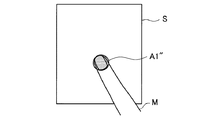
[3. Method for detecting operation tool M]
In the
操作体検出部107は、センサ画像Sに基づいて各画素に対応する受光状態を表す輝度値を算出し、所定の閾値を用いて輝度値を2値化処理する。2値化処理では、各画素の輝度値が第1または第2のカテゴリに分類され、センサ画像Sの領域が各カテゴリに対応する第1または第2の領域A1、A2に区分される。第1および第2の領域A1、A2は、輝度大、輝度小の領域に対応しており、操作体Mの接触領域、非接触領域として各々に特定される。
The operating
操作体検出部107は、第1の領域A1の存在に基づいて、表示パネル101に対する操作体Mの接触の有無を検出する。また、操作体検出部107は、第1の領域A1の重心位置および面積を算出することで、操作体Mの接触位置および接触面積を各々に検出する。
The operating
特に、操作体検出部107は、第1の領域A1の長軸方向Dを特定することで、操作体Mの指示方向を検出する。操作体Mの指示方向は、第1の領域A1の長軸方向Dに沿って表示パネル101の上部を指示する方向として定義される。制御部115は、操作体Mの指示方向の回転前と回転後の角度差分を算出することで、操作体Mの回転角度を算出する。
In particular, the operating
以下では、図3A〜図3Cを参照しながら、操作体Mの指示方向の検出方法について説明する。図3A〜図3Cは、表示パネル101上での操作体Mの位置および操作体Mの検出結果を示す図である。
Below, the detection method of the instruction | indication direction of the operation body M is demonstrated, referring FIG. 3A-FIG. 3C. 3A to 3C are diagrams illustrating the position of the operating tool M on the
図3Aでは、操作体Mである指先の接触領域A1がセンサ画像S上で、楕円形の領域A1として捉えられている。この場合、操作体検出部107は、楕円形の領域A1の長軸方向Dを特定し、特定された長軸方向Dに沿って表示パネル101の上部を指示する方向を操作体Mの指示方向として検出する。通常、表示パネル101に対する指先の接触領域A1は、指の指示方向を長軸方向Dとする楕円形の領域A1として捉えられる。
In FIG. 3A, the contact area A1 of the fingertip that is the operating tool M is captured on the sensor image S as an elliptical area A1. In this case, the operating
図3Bでは、図3Aの状態から指先が回転され、回転後の指先の接触領域A1’がセンサ画像S上で、楕円形の領域A1’として捉えられている。この場合、操作体検出部107は、楕円形の領域A1’の長軸方向Dを特定し、特定された長軸方向Dに沿って表示パネル101の上部を指示する方向を回転後の操作体Mの指示方向として検出する。そして、制御部115は、操作体Mの指示方向の回転前と回転後の角度差分に基づいて、操作体Mの回転角度を算出する。
In FIG. 3B, the fingertip is rotated from the state of FIG. 3A, and the contact area A <b> 1 ′ of the rotated fingertip is captured as an elliptical area A <b> 1 ′ on the sensor image S. In this case, the operating
一方、図3Cでは、指先の接触領域A1’’がセンサ画像S上で、略円形の領域A1’’として捉えられている。この場合、操作体検出部107は、接触領域A1’’の長軸方向Dを特定できないので、制御部115は、検出エラーとみなす。
On the other hand, in FIG. 3C, the fingertip contact area A <b> 1 ″ is captured on the sensor image S as a substantially circular area A <b> 1 ″. In this case, since the operating
[4.地図情報表示方法]
図4は、本発明の実施形態に係る地図情報表示方法を示すフロー図である。図5は、地図情報MIおよび視野画像情報VIの表示例を示す図である。図6は、視点移動に係る表示例を示す図であり、図7は、視線方向変更に係る表示例を示す図である。
[4. Map information display method]
FIG. 4 is a flowchart showing a map information display method according to the embodiment of the present invention. FIG. 5 is a diagram illustrating a display example of the map information MI and the visual field image information VI. FIG. 6 is a diagram illustrating a display example relating to viewpoint movement, and FIG. 7 is a diagram illustrating a display example relating to a change in the viewing direction.
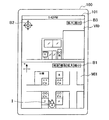
表示パネル101には、地図情報MI、および地図情報MI上で指定される視点および視線方向に応じた視野画像情報VIが表示されている。地図情報MI上には、指定されている視点および視線方向(矢印の向き)を示す視点アイコンIが地図情報MI上の視点に対応する位置に表示されている。
The
図5に示す例では、地図情報MI1上の視線方向(北北西方向)に対応する視野画像情報VI0(郵便局等を表す写真)が表示されている。これにより、ユーザは、地図情報MI1上の視点および視線方向を容易に把握できる。 In the example shown in FIG. 5, visual field image information VI0 (a photograph showing a post office or the like) corresponding to the line-of-sight direction (north-northwest direction) on the map information MI1 is displayed. Thereby, the user can easily grasp the viewpoint and the line-of-sight direction on the map information MI1.
また、地図情報MI1上には、地図情報MIの拡大縮小、地図情報MIの選択を行うためのGUIボタンB1等が表示されている。また、視野画像情報VI上には、視野画像情報VIの拡大縮小、視野画像情報VIの移動を行うためのGUIボタンB2、B3等が表示されている。 Further, on the map information MI1, a GUI button B1 and the like for performing the enlargement / reduction of the map information MI and the selection of the map information MI are displayed. Further, on the view image information VI, GUI buttons B2, B3, etc. for performing enlargement / reduction of the view image information VI and movement of the view image information VI are displayed.
図4に示すように、操作体検出部107は、検出フレーム毎に操作体Mの接触状態を検出する(ステップS101)。制御部115は、操作体Mが表示パネル101に接触しているかを判定する(S103)。制御部115は、判定結果が肯定的であれば、ステップS105以降の処理を行い、判定結果が否定的であれば、ステップS101の処理に復帰する。
As shown in FIG. 4, the operating
ステップS105において、制御部115は、操作体Mが視点アイコンIに対応する領域に接触していないかを判定する。制御部115は、判定結果が肯定的であれば、ステップS107の処理を行い、判定結果が否定的であれば、ステップS111以降の処理を行う。
In step S <b> 105, the
ステップS107において、操作体検出部107は、後続のフレームで地図情報MIまたは視野画像情報VIに対するクリック、ドラッグ、ドロップ、フリック操作等の通常操作を検出する。そして、制御部115は、検出された操作に対応する処理を行う(S109)。
In step S107, the operation
ステップS111において、操作体検出部107は、後続のフレームで操作体Mによる視点アイコンIのドラッグ操作を検出する。ドラッグ操作とは、表示パネル101上で、視点アイコンI等に対応する領域に操作体Mを接触させた状態で操作体Mを移動させる操作を意味する。制御部115は、操作体Mの位置がドラッグ操作により直前のフレームから移動されているかを判定する(S113)。制御部115は、判定結果が肯定的であれば、ステップS115以降の処理を行い、判定結果が否定的であれば、ステップS123以降の処理を行う。
In step S111, the operation
ステップS115において、制御部115は、移動後の操作体Mの位置に応じて視点の情報を更新する。表示制御部111は、移動後の操作体Mの位置に視点アイコンIを表示するように表示パネル101(表示部105)を制御する(S117)。
In step S115, the
制御部115は、移動後の視点に応じて、地図情報MIの緯度・経度、方角に対応する視野画像情報VIの存在を記憶部113に照会し(S119)、対応する視野画像情報VIが存在する場合、視野画像情報VIの更新を画像生成部109に指示する。画像生成部109は、移動後の視点に応じた視野画像情報VIを記憶部113から読出して画像データを生成し、表示制御部111に出力し、表示パネル101上で視野画像情報VIの表示が更新される(S121)。
The
図6に示すように、操作体Mの位置が地図情報MI1上でドラッグ操作により移動されると、移動後の操作体Mの位置に視点アイコンIが表示される。そして、移動後の視点に対応する視野画像情報VIが存在する場合、視野画像情報VIの表示が更新される。図6に示す例では、視点アイコンIが北方向に移動されており、視線方向(北北西方向)に対応する視野画像情報VI1(××ビル、公園等を表す写真)が表示されている。 As shown in FIG. 6, when the position of the operating tool M is moved on the map information MI1 by a drag operation, the viewpoint icon I is displayed at the position of the operating tool M after the movement. And when the visual field image information VI corresponding to the viewpoint after movement exists, the display of the visual field image information VI is updated. In the example shown in FIG. 6, the viewpoint icon I is moved in the north direction, and visual field image information VI1 (a photograph representing a building, a park, or the like) corresponding to the line-of-sight direction (north-northwest direction) is displayed.
ここで、操作体Mの位置の連続的な移動に応じて、移動経路上の各視点に対応する視野画像情報VIが存在する場合、視野画像情報VIの表示が移動経路上で順次に更新されてもよい。例えば、図6に示す例では、視点の移動に応じて、視野画像情報VIとして、郵便局→○○ビル→交差点→××ビル→公園を表す写真が順次に表示されてもよい。 Here, when the visual field image information VI corresponding to each viewpoint on the movement path exists in accordance with the continuous movement of the position of the operating tool M, the display of the visual field image information VI is sequentially updated on the movement path. May be. For example, in the example shown in FIG. 6, according to the movement of the viewpoint, photographs representing a post office → XXX building → intersection → XX building → park may be sequentially displayed as the visual field image information VI.
ステップS123において、操作体検出部107は、後続のフレームで操作体Mによる視点アイコンIの回転操作を検出する。制御部115は、操作体Mの指示方向が回転操作により直前のフレームから変更されているかを判定する(S125)。制御部115は、判定結果が肯定的であれば、ステップS127以降の処理を行い、判定結果が否定的であれば、ステップS101の処理に復帰する。
In step S123, the operation
ステップS127において、制御部115は、変更後の操作体Mの指示方向に応じて視線方向の情報を更新する。ここで、制御部115は、操作体Mの指示方向と一致するように地図情報MI上の視線方向を更新する。表示制御部111は、変更後の操作体Mの指示方向を示す視点アイコンIを表示するように表示パネル101(表示部105)を制御する(S129)。
In step S127, the
制御部115は、変更後の視線方向に応じて、地図情報MIの緯度・経度、方角に対応する視野画像情報VIの存在を記憶部113に照会し(S131)、対応する視野画像情報VIが存在する場合、視野画像情報VIの更新を画像生成部109に指示する。画像生成部109は、変更後の視線方向に応じた視野画像情報VIを記憶部113から読出して画像データを生成し、表示制御部111に出力し、表示パネル101上で視野画像情報VIの表示が更新される(S133)。
The
図7に示すように、視点アイコンI上で操作体Mの指示方向が回転操作により時計回りに60°変更されると、時計回りに60°変更された視線方向を示す視点アイコンI’が表示される。ここで、視点アイコンI’は、操作体Mの指示方向と一致する、地図情報MI1上の変更後の視線方向を示している。 As shown in FIG. 7, when the pointing direction of the operating tool M is changed 60 ° clockwise by the rotation operation on the viewpoint icon I, the viewpoint icon I ′ indicating the line-of-sight direction changed 60 ° clockwise is displayed. Is done. Here, the viewpoint icon I ′ indicates the line-of-sight direction after the change on the map information MI1 that matches the instruction direction of the operating tool M.
そして、変更後の視線方向に対応する視野画像情報VIが存在する場合、視野画像情報VIの表示が更新される。図7に示す例では、視線方向の変更前後で、視線方向(北北西方向、北北東方向)に対応する視野画像情報VI1(××ビル、公園等を表す写真)、VI2(△△ビル、学校等を表す写真)が各々に表示されている。これにより、地図情報MI上の視線方向が操作体Mの指示方向に一致しているので、ユーザは、地図情報MI上の視線方向を直感的に指定できる。 When the visual field image information VI corresponding to the changed line-of-sight direction exists, the display of the visual field image information VI is updated. In the example shown in FIG. 7, visual field image information VI1 (a photograph representing a building, park, etc.) VI2 (ΔΔ building, A photograph showing a school etc.) is displayed on each. As a result, since the line-of-sight direction on the map information MI matches the instruction direction of the operating tool M, the user can intuitively specify the line-of-sight direction on the map information MI.
ここで、操作体Mの指示方向の連続的な変更に応じて、変更途中の各視線方向に対応する視野画像情報VIが存在する場合、視野画像情報VIの表示が変更途中で順次に更新されてもよい。例えば、図7に示す例では、視線方向の変更に応じて、視野画像情報VIとして、××ビル→公園→道路→学校→△△ビルを表す写真が順次に表示されてもよい。 Here, in accordance with the continuous change of the indication direction of the operating tool M, when the visual field image information VI corresponding to each line-of-sight direction being changed exists, the display of the visual field image information VI is sequentially updated during the change. May be. For example, in the example illustrated in FIG. 7, photographs representing xx building → park → road → school → ΔΔ building may be sequentially displayed as the visual field image information VI in accordance with the change in the viewing direction.
なお、移動後の視点または変更後の視線方向に対応する視野画像情報VIが存在しない場合、視野画像情報VIの表示を更新しなくてもよく、または所定の画像情報を表示してもよい。 When there is no visual field image information VI corresponding to the viewpoint after movement or the line-of-sight direction after change, the display of the visual field image information VI may not be updated, or predetermined image information may be displayed.
また、上記説明では、操作体Mによるドラッグ操作の検出後に回転操作の検出が行われているが、回転操作の検出後にドラッグ操作の検出が行われてもよい。これにより、操作体Mの指示方向の検出に前後して操作体Mの移動が検出されることで、ユーザは、地図情報MI上の視線方向の変更および視点の位置の変更を連続して容易に操作できる。 In the above description, the rotation operation is detected after the drag operation is detected by the operating tool M. However, the drag operation may be detected after the rotation operation is detected. Thereby, by detecting the movement of the operation tool M before and after the detection of the indication direction of the operation tool M, the user can easily change the line-of-sight direction and the viewpoint position on the map information MI continuously. Can be operated.
[5.変形例]
図8〜図10は、地図情報表示に係る第1〜第3の変形例を示す図である。
[5. Modified example]
8-10 is a figure which shows the 1st-3rd modification which concerns on map information display.
上記実施形態では、地図情報MI上の視線方向が操作体Mの指示方向と一致する場合について説明した。この場合、操作体Mの指示方向の変更範囲が限定されてしまい、回転操作時の操作性が低下してしまう場合がある。例えば、操作体Mである指の指示方向を180°回転させることは一般に困難を伴う。 In the embodiment described above, the case where the line-of-sight direction on the map information MI matches the instruction direction of the operating tool M has been described. In this case, the change range of the pointing direction of the operating tool M is limited, and the operability during the rotation operation may be reduced. For example, it is generally difficult to rotate the pointing direction of the finger that is the operation tool M by 180 °.
このため、第1の変形例では、操作体Mの指示方向と一致する視線方向ではなく、操作体Mの指示方向の変化量に係数a(1<a)を乗じた変化量で規定される視線方向に応じて、視野画像情報VIの表示を制御する。 For this reason, in the first modification, not the line-of-sight direction that matches the instruction direction of the operating tool M, but the amount of change obtained by multiplying the change amount of the operating tool M in the indicated direction by the coefficient a (1 <a). The display of the visual field image information VI is controlled according to the line-of-sight direction.
例えば、係数a=2であれば、図8に示すように、視点アイコンI上での操作体Mの指示方向が回転操作により時計回りに30°変更されると、時計回りに60°(=30°×2)変更された視線方向を示す視点アイコンI’が表示され、変更後の視線方向に対応する視野画像情報VI2が表示される。 For example, when the coefficient a = 2, as shown in FIG. 8, when the pointing direction of the operating tool M on the viewpoint icon I is changed 30 ° clockwise by the rotation operation, 60 ° clockwise (= 30 ° × 2) A viewpoint icon I ′ indicating the changed line-of-sight direction is displayed, and visual field image information VI2 corresponding to the changed line-of-sight direction is displayed.
これにより、地図情報MI上の視線方向が操作体Mの指示方向の変化量に係数a(1<a)を乗じた変化量で規定されるので、ユーザは、指示方向の僅かな変化でも地図情報MI上の視線方向を容易に指定できる。しかし、第1の変形例では、指示方向と視線方向が一致しないので、直感的な操作により視線方向を指定できない場合がある。 As a result, the line-of-sight direction on the map information MI is defined by a change amount obtained by multiplying the change amount of the pointing direction of the operating tool M by the coefficient a (1 <a). The line-of-sight direction on the information MI can be easily specified. However, in the first modified example, since the instruction direction and the line-of-sight direction do not match, the line-of-sight direction may not be designated by an intuitive operation.
このため、第2の変形例では、操作体Mの指示方向の変化量に係数a(1<a)を乗じた変化量で規定される視線方向を特定するとともに、操作体Mの指示方向の変化量に係数(1−a)を乗じた変化量で地図情報MIを回転させる。 For this reason, in the second modification, the line-of-sight direction defined by the amount of change obtained by multiplying the amount of change in the pointing direction of the operating tool M by the coefficient a (1 <a) is specified, and the direction of the pointing of the operating tool M is determined. The map information MI is rotated by a change amount obtained by multiplying the change amount by a coefficient (1-a).
例えば、係数a=2であれば、図9に示すように、視点アイコンI上で操作体Mの指示方向が回転操作により時計回りに30°変更されるとともに、矢印MDで示すように、地図情報MIが時計回りに−30°(=30°×(−1))、つまり反時計回りに30°回転される。そして、地図情報MI1に対して時計回りに60°変更された視線方向を示す視点アイコンI’が表示され、変更後の視線方向に対応する視野画像情報VI2が表示される。 For example, if the coefficient a = 2, as shown in FIG. 9, the indication direction of the operating tool M is changed 30 ° clockwise by the rotation operation on the viewpoint icon I, and the map is indicated by the arrow MD as shown in FIG. The information MI is rotated clockwise by −30 ° (= 30 ° × (−1)), that is, counterclockwise by 30 °. Then, the viewpoint icon I ′ indicating the line-of-sight direction changed 60 ° clockwise relative to the map information MI1 is displayed, and the visual field image information VI2 corresponding to the changed line-of-sight direction is displayed.
ここで、操作体Mの指示方向が時計回りに30°変更され、地図情報MI1が反時計回りに30°変更された地図情報MI2となるので、操作体Mの指示方向が地図情報MI2上の視線方向と一致することになる。 Here, since the indication direction of the operating tool M is changed by 30 ° clockwise and the map information MI1 becomes the map information MI2 changed by 30 ° counterclockwise, the indicating direction of the operating tool M is on the map information MI2. This coincides with the line-of-sight direction.
これにより、指示方向の変化量に係数aを乗じた変化量で規定される地図情報MI上の視線方向に応じた視野画像情報VIを表示する場合に比べて、ユーザは、地図情報MI上の視線方向を直感的に指定できる。 Thereby, compared with the case where the visual field image information VI corresponding to the line-of-sight direction on the map information MI defined by the change amount obtained by multiplying the change amount of the indication direction by the coefficient a is displayed, the user can You can specify the line-of-sight direction intuitively.
第2の変形例では、操作体Mの指示方向の変化に応じて、地図情報MI上の視線方向および地図情報MIの表示方向が変更される。しかし、第2の変形例では、地図情報MIの表示方向とともに、地図情報MI上の視線方向も変更されてしまい、視野画像情報VIの表示も変更されてしまう。一方、ユーザは、視野画像情報VIの表示を維持した状態で、地図情報MIの表示方向の変更のみを所望する場合がある。 In the second modification, the line-of-sight direction on the map information MI and the display direction of the map information MI are changed according to the change in the indication direction of the operating tool M. However, in the second modification, the line-of-sight direction on the map information MI is changed together with the display direction of the map information MI, and the display of the view image information VI is also changed. On the other hand, the user may only desire to change the display direction of the map information MI while maintaining the display of the visual field image information VI.
このため、第3の変形例では、第1および第2の操作体M1、M2を用いて、地図情報MIの表示方向を変更する操作が提案される。ここで、第1の操作体M1と第2の操作体M2は、例えば、ユーザの中指と人差指、人差指と親指に各々に対応する。 For this reason, in the 3rd modification, operation which changes the display direction of map information MI using the 1st and 2nd operation bodies M1 and M2 is proposed. Here, the first operation body M1 and the second operation body M2 correspond to, for example, the middle finger and index finger of the user, and the index finger and thumb, respectively.
図10に示すように、例えば中指である第1の操作体M1により視点アイコンIを指定した状態で、地図情報MI1上で弧を描くように、人差指である第2の操作体M2を表示パネル101上で移動させる。ここで、反時計回りに30°の円弧を描くことで、矢印MDで示すように、反時計回りに30°回転された地図情報MI2が表示される。なお、第1の変形例と同様に、第2の操作体M2の指示方向の変化量に1以上の係数を乗じた変化量で地図情報MI1の表示方向を変化させてもよい。これにより、ユーザは、視野画像情報VIの表示を維持した状態で、地図情報MIの表示方向を変更できる。 As shown in FIG. 10, for example, in a state where the viewpoint icon I is designated by the first operating tool M1 that is the middle finger, the second operating tool M2 that is the index finger is displayed on the display panel so as to draw an arc on the map information MI1. Move on 101. Here, by drawing a 30 ° arc in the counterclockwise direction, as indicated by the arrow MD, the map information MI2 rotated by 30 ° in the counterclockwise direction is displayed. Similar to the first modification, the display direction of the map information MI1 may be changed by a change amount obtained by multiplying the change amount of the indication direction of the second operating tool M2 by one or more coefficients. Thereby, the user can change the display direction of the map information MI while maintaining the display of the visual field image information VI.
また、地図情報MIの表示方向の変更は、図7〜図9を参照しながら説明した視線方向の変更方法と組合せてもよい。これにより、ユーザは、地図情報MI上の視線方向の変更および地図情報MIの表示方向の変更を連続して容易に操作できる。 Further, the change of the display direction of the map information MI may be combined with the method of changing the line-of-sight direction described with reference to FIGS. Thus, the user can easily and continuously operate the change of the line-of-sight direction on the map information MI and the change of the display direction of the map information MI.
[6.まとめ]
以上説明したように、本発明の実施形態によれば、地図情報表示装置100は、地図情報MIおよび視野画像情報VIが表示される表示パネル101上で、地図情報MIに対応する領域に接触する操作体Mの位置および指示方向を検出する。そして、地図情報表示装置100は、操作体Mの位置により指定される地図情報MI上の視点、および操作体Mの指示方向により指定される地図情報MI上の視線方向に応じて、視野画像情報VIの表示を制御する。
[6. Summary]
As described above, according to the embodiment of the present invention, the map
これにより、地図情報MI上で操作体Mの位置および指示方向により指定される視点および視線方向に応じた視野画像情報VIが表示されることで、ユーザは、地図情報MIおよび視野画像情報VI等の地図関連情報を直感的かつ容易に操作できる。 As a result, the visual field image information VI corresponding to the viewpoint and line-of-sight direction specified by the position and the pointing direction of the operating tool M is displayed on the map information MI, so that the user can view the map information MI, the visual field image information VI, and the like. The map related information can be operated intuitively and easily.
以上、添付図面を参照しながら本発明の好適な実施形態について説明したが、本発明は係る例に限定されない。当業者であれば、特許請求の範囲に記載された技術的思想の範疇内において、各種の変更例または修正例に想到し得ることは明らかであり、それらについても当然に本発明の技術的範囲に属するものと了解される。 As mentioned above, although preferred embodiment of this invention was described referring an accompanying drawing, this invention is not limited to the example which concerns. It is obvious for those skilled in the art that various changes or modifications can be conceived within the scope of the technical idea described in the claims. It is understood that it belongs to.
例えば上記実施形態の説明では、光学式の接触センサ103を用いて、操作体Mの接触状態を検出する場合について説明した。しかし、静電容量式、圧力式等、他の接触センサが用いられてもよい。
For example, in the description of the above embodiment, the case where the contact state of the operating tool M is detected using the
例えば上記実施形態の説明では、操作体Mの接触状態から操作体Mの指示方向を検出する場合について説明した。しかし、操作体Mの接触状態および近接状態から操作体Mの指示方向を検出してもよい。この場合、例えば、接触近接センサの出力結果によるセンサ画像を3値化処理し、操作体Mの接触領域、近接領域、非接触近接領域を特定する。そして、接触領域および近接領域の重心位置に基づいて、近接領域の重心位置から接触領域の重心位置に向かう方向を操作体Mの指示方向として検出できる。 For example, in the description of the above embodiment, a case has been described in which the indication direction of the operating tool M is detected from the contact state of the operating tool M. However, the indication direction of the operating tool M may be detected from the contact state and the proximity state of the operating tool M. In this case, for example, the sensor image based on the output result of the contact proximity sensor is ternarized, and the contact area, proximity area, and non-contact proximity area of the operating tool M are specified. Then, based on the gravity center positions of the contact area and the proximity area, the direction from the gravity center position of the proximity area to the gravity center position of the contact area can be detected as the indication direction of the operating tool M.
100 情報処理装置
101 表示パネル
107 操作体検出部
111 表示制御部
M、M1、M2 操作体
MI 地図情報
VI、VI0、VI1、VI2 視野画像情報
I、I’ 視点アイコン
DESCRIPTION OF
Claims (9)
前記操作体の接触位置により指定される前記地図情報上の視点、および前記操作体の指示方向により指定される前記地図情報上の視線方向に応じて、前記視野画像情報の表示を制御する表示制御部と、
を備える地図情報表示装置。 On the display unit on which the map information and the visual field image information are displayed, the contact position of the operating body that touches the area corresponding to the map information, and the change by the rotation operation that is the operation of changing the direction of the operating body at the contact position An operating body detection unit for detecting a direction indicated by the operating body;
Display control for controlling display of the visual field image information in accordance with a viewpoint on the map information specified by the contact position of the operating body and a line-of-sight direction on the map information specified by an instruction direction of the operating body And
A map information display device comprising:
前記表示制御部は、移動後の操作体の位置により指定される前記地図情報上の視点、および前記操作体の指示方向により指定される前記地図情報上の視線方向に応じて、前記視野画像情報の表示を制御する、請求項1に記載の地図情報表示装置。 The operating tool detection unit detects the movement of the operating tool that moves in contact with an area corresponding to the map information before and after detection of the indication direction of the operating tool.
The display control unit includes the visual field image information according to a viewpoint on the map information specified by the position of the operating body after movement, and a line-of-sight direction on the map information specified by an instruction direction of the operating body. The map information display device according to claim 1, wherein display of the map information is controlled.
前記操作体検出部は、前記地図情報上の前記視点情報に対応する領域に接触する第1の操作体を検出している状態で、前記第1の操作体の検知領域を中心とする弧を描くように、前記地図情報に対応する領域に接触して移動する第2の操作体の移動を検出し、
前記表示制御部は、検出される前記第2の操作体の移動に応じて、前記視点情報を回転中心とする前記地図情報の回転表示を制御する、請求項1に記載の地図情報表示装置。 The display control unit displays viewpoint information indicating a viewpoint on the map information at a position corresponding to the viewpoint on the map information,
The operating body detection unit detects an arc centering on a detection area of the first operating body in a state where the first operating body is in contact with an area corresponding to the viewpoint information on the map information. As illustrated, the movement of the second operating body that moves in contact with the area corresponding to the map information is detected,
The map information display device according to claim 1, wherein the display control unit controls the rotation display of the map information with the viewpoint information as a rotation center in accordance with the detected movement of the second operating body.
前記操作体の接触位置により指定される前記地図情報上の視点、および前記操作体の指示方向により指定される前記地図情報上の視線方向に応じて、前記視野画像情報の表示を制御するステップと、
を含む地図情報表示方法。 On the display unit on which the map information and the visual field image information are displayed, the contact position of the operating body that touches the area corresponding to the map information, and the change by the rotation operation that is the operation of changing the direction of the operating body at the contact position Detecting the indicated direction of the operating body ;
Controlling the display of the visual field image information according to the viewpoint on the map information specified by the contact position of the operating body and the line-of-sight direction on the map information specified by the pointing direction of the operating body; ,
Map information display method including
前記操作体の接触位置により指定される前記地図情報上の視点、および前記操作体の指示方向により指定される前記地図情報上の視線方向に応じて、前記視野画像情報の表示を制御するステップと、
を含む地図情報表示方法をコンピュータに実行させるためのプログラム。 On the display unit on which the map information and the visual field image information are displayed, the contact position of the operating body that touches the area corresponding to the map information, and the change by the rotation operation that is the operation of changing the direction of the operating body at the contact position Detecting a direction indicated by the operating body ;
Controlling the display of the visual field image information according to the viewpoint on the map information specified by the contact position of the operating body and the line-of-sight direction on the map information specified by the pointing direction of the operating body; ,
A program for causing a computer to execute a map information display method including:
Priority Applications (5)
| Application Number | Priority Date | Filing Date | Title |
|---|---|---|---|
| JP2009159148A JP5792424B2 (en) | 2009-07-03 | 2009-07-03 | MAP INFORMATION DISPLAY DEVICE, MAP INFORMATION DISPLAY METHOD, AND PROGRAM |
| EP10166337.5A EP2270767B1 (en) | 2009-07-03 | 2010-06-17 | Device, Method and Program for Displaying Map Information |
| US12/821,444 US9251722B2 (en) | 2009-07-03 | 2010-06-23 | Map information display device, map information display method and program |
| CN2010102149633A CN101944304B (en) | 2009-07-03 | 2010-06-28 | Device, method and program for displaying map information |
| US14/789,123 US10755604B2 (en) | 2009-07-03 | 2015-07-01 | Map information display device, map information display method and program |
Applications Claiming Priority (1)
| Application Number | Priority Date | Filing Date | Title |
|---|---|---|---|
| JP2009159148A JP5792424B2 (en) | 2009-07-03 | 2009-07-03 | MAP INFORMATION DISPLAY DEVICE, MAP INFORMATION DISPLAY METHOD, AND PROGRAM |
Publications (3)
| Publication Number | Publication Date |
|---|---|
| JP2011014045A JP2011014045A (en) | 2011-01-20 |
| JP2011014045A5 JP2011014045A5 (en) | 2012-08-23 |
| JP5792424B2 true JP5792424B2 (en) | 2015-10-14 |
Family
ID=42942222
Family Applications (1)
| Application Number | Title | Priority Date | Filing Date |
|---|---|---|---|
| JP2009159148A Active JP5792424B2 (en) | 2009-07-03 | 2009-07-03 | MAP INFORMATION DISPLAY DEVICE, MAP INFORMATION DISPLAY METHOD, AND PROGRAM |
Country Status (4)
| Country | Link |
|---|---|
| US (2) | US9251722B2 (en) |
| EP (1) | EP2270767B1 (en) |
| JP (1) | JP5792424B2 (en) |
| CN (1) | CN101944304B (en) |
Families Citing this family (39)
| Publication number | Priority date | Publication date | Assignee | Title |
|---|---|---|---|---|
| JP5402322B2 (en) * | 2009-07-02 | 2014-01-29 | ソニー株式会社 | Information processing apparatus and information processing method |
| JP5792424B2 (en) | 2009-07-03 | 2015-10-14 | ソニー株式会社 | MAP INFORMATION DISPLAY DEVICE, MAP INFORMATION DISPLAY METHOD, AND PROGRAM |
| WO2012154365A2 (en) | 2011-04-12 | 2012-11-15 | Google Inc. | Integrating maps and street views |
| US8825392B2 (en) | 2011-06-30 | 2014-09-02 | Navteq B.V. | Map view |
| US9202297B1 (en) * | 2011-07-12 | 2015-12-01 | Domo, Inc. | Dynamic expansion of data visualizations |
| US10001898B1 (en) | 2011-07-12 | 2018-06-19 | Domo, Inc. | Automated provisioning of relational information for a summary data visualization |
| US9792017B1 (en) | 2011-07-12 | 2017-10-17 | Domo, Inc. | Automatic creation of drill paths |
| US9619138B2 (en) * | 2012-06-19 | 2017-04-11 | Nokia Corporation | Method and apparatus for conveying location based images based on a field-of-view |
| JP6007377B2 (en) * | 2012-11-14 | 2016-10-12 | ピーアンドダブリューソリューションズ株式会社 | Seat layout display device, method and program |
| JP6033061B2 (en) * | 2012-11-30 | 2016-11-30 | Kddi株式会社 | Input device and program |
| US20140152586A1 (en) * | 2012-11-30 | 2014-06-05 | Kabushiki Kaisha Toshiba | Electronic apparatus, display control method and storage medium |
| US9063582B2 (en) | 2012-12-28 | 2015-06-23 | Nokia Technologies Oy | Methods, apparatuses, and computer program products for retrieving views extending a user's line of sight |
| TW201508150A (en) * | 2013-08-27 | 2015-03-01 | Hon Hai Prec Ind Co Ltd | Remote control key for vehicles |
| US20150130843A1 (en) * | 2013-11-14 | 2015-05-14 | Microsoft Corporation | Lens view for map |
| US10598780B2 (en) * | 2013-12-04 | 2020-03-24 | Groundprobe Pty Ltd | Method and system for displaying an area |
| JP2015152483A (en) * | 2014-02-17 | 2015-08-24 | Necネッツエスアイ株式会社 | Location information acquisition system and location information acquisition method |
| US10664772B1 (en) | 2014-03-07 | 2020-05-26 | Steelcase Inc. | Method and system for facilitating collaboration sessions |
| PL2925029T3 (en) * | 2014-03-25 | 2017-07-31 | Nokia Technologies Oy | Performance of a location response action |
| USD776200S1 (en) * | 2014-05-27 | 2017-01-10 | Amazon Technologies, Inc. | Label with a touch graphic |
| US20150346998A1 (en) * | 2014-05-30 | 2015-12-03 | Qualcomm Incorporated | Rapid text cursor placement using finger orientation |
| US9955318B1 (en) * | 2014-06-05 | 2018-04-24 | Steelcase Inc. | Space guidance and management system and method |
| US9380682B2 (en) | 2014-06-05 | 2016-06-28 | Steelcase Inc. | Environment optimization for space based on presence and activities |
| US9766079B1 (en) | 2014-10-03 | 2017-09-19 | Steelcase Inc. | Method and system for locating resources and communicating within an enterprise |
| US11744376B2 (en) | 2014-06-06 | 2023-09-05 | Steelcase Inc. | Microclimate control systems and methods |
| US20160062636A1 (en) * | 2014-09-02 | 2016-03-03 | Lg Electronics Inc. | Mobile terminal and control method thereof |
| US9852388B1 (en) | 2014-10-03 | 2017-12-26 | Steelcase, Inc. | Method and system for locating resources and communicating within an enterprise |
| KR20160047204A (en) * | 2014-10-22 | 2016-05-02 | 현대자동차주식회사 | Touch apparatus and method for controlling thereof |
| US9990117B2 (en) * | 2015-08-04 | 2018-06-05 | Lenovo (Singapore) Pte. Ltd. | Zooming and panning within a user interface |
| JP6543173B2 (en) * | 2015-11-18 | 2019-07-10 | 京セラ株式会社 | Portable electronic device, control method and control program |
| US10386931B2 (en) | 2016-01-27 | 2019-08-20 | Lenovo (Singapore) Pte. Ltd. | Toggling between presentation and non-presentation of representations of input |
| US10768740B2 (en) * | 2016-03-03 | 2020-09-08 | Hewlett-Packard Development Company, L.P. | Input axis rotations |
| US9921726B1 (en) | 2016-06-03 | 2018-03-20 | Steelcase Inc. | Smart workstation method and system |
| KR102576654B1 (en) * | 2016-10-18 | 2023-09-11 | 삼성전자주식회사 | Electronic apparatus and controlling method thereof |
| US10264213B1 (en) | 2016-12-15 | 2019-04-16 | Steelcase Inc. | Content amplification system and method |
| WO2018186011A1 (en) * | 2017-04-03 | 2018-10-11 | ソニー株式会社 | Information processing device, information processing method, and program |
| US10360709B2 (en) * | 2017-04-05 | 2019-07-23 | Microsoft Technology Licensing, Llc | Rendering images on map using orientations |
| JP7265822B2 (en) | 2018-08-27 | 2023-04-27 | キヤノン株式会社 | Display control device, display control method, and program |
| JP7119798B2 (en) * | 2018-09-07 | 2022-08-17 | 株式会社アイシン | display controller |
| US11984739B1 (en) | 2020-07-31 | 2024-05-14 | Steelcase Inc. | Remote power systems, apparatus and methods |
Family Cites Families (65)
| Publication number | Priority date | Publication date | Assignee | Title |
|---|---|---|---|---|
| US5552982A (en) | 1990-10-31 | 1996-09-03 | Microsoft Corporation | Method and system for processing fields in a document processor |
| WO1996009579A1 (en) * | 1994-09-22 | 1996-03-28 | Izak Van Cruyningen | Popup menus with directional gestures |
| JP3320295B2 (en) * | 1996-02-22 | 2002-09-03 | キヤノン株式会社 | Information processing apparatus and control method therefor |
| JPH10198517A (en) * | 1997-01-10 | 1998-07-31 | Tokyo Noukou Univ | Method for controlling display content of display device |
| US6346938B1 (en) * | 1999-04-27 | 2002-02-12 | Harris Corporation | Computer-resident mechanism for manipulating, navigating through and mensurating displayed image of three-dimensional geometric model |
| JP3410703B2 (en) * | 2000-01-31 | 2003-05-26 | ディー・リンク株式会社 | Image display method |
| JP2001265523A (en) * | 2000-03-21 | 2001-09-28 | Sony Corp | Information input/output system, information input/ output method and program storage medium |
| JP2004507724A (en) * | 2000-08-24 | 2004-03-11 | シーメンス アクチエンゲゼルシヤフト | Method for displaying target information, method for navigating in a map screen, computer program product and navigation device |
| JP2003106853A (en) * | 2001-09-28 | 2003-04-09 | Toshiba Corp | Drive supporting apparatus |
| US7411594B2 (en) * | 2002-01-15 | 2008-08-12 | Canon Kabushiki Kaisha | Information processing apparatus and method |
| JP2003208146A (en) * | 2002-01-15 | 2003-07-25 | Canon Inc | Image display device and information processing method |
| AU2003223090A1 (en) | 2002-04-30 | 2003-11-17 | Telmap Ltd. | Template-based map distribution system |
| JP2004005272A (en) * | 2002-05-31 | 2004-01-08 | Cad Center:Kk | Virtual space movement control device, method and program |
| JP4007549B2 (en) | 2002-06-28 | 2007-11-14 | クラリオン株式会社 | Peripheral information presentation device and method in navigation, and presentation program |
| JP4181372B2 (en) * | 2002-09-27 | 2008-11-12 | 富士フイルム株式会社 | Display device, image information management terminal, image information management system, and image display method |
| US7401732B2 (en) * | 2002-12-30 | 2008-07-22 | Haddad Michael A | Apparatus for reading standardized personal identification credentials for integration with automated access control systems |
| JP4105609B2 (en) | 2003-01-06 | 2008-06-25 | アルパイン株式会社 | 3D display method for navigation and navigation apparatus |
| JP4297804B2 (en) * | 2004-02-19 | 2009-07-15 | 任天堂株式会社 | GAME DEVICE AND GAME PROGRAM |
| JP4526307B2 (en) | 2004-06-09 | 2010-08-18 | 富士通テン株式会社 | Function selection device |
| US7376510B1 (en) * | 2004-11-05 | 2008-05-20 | Navteq North America, Llc | Map display for a navigation system |
| EP1832038B1 (en) * | 2004-12-22 | 2013-10-02 | BCE Inc. | User authentication for contact-less systems |
| JP4738019B2 (en) * | 2005-02-23 | 2011-08-03 | 任天堂株式会社 | GAME PROGRAM, GAME DEVICE, GAME CONTROL METHOD, AND GAME SYSTEM |
| MX2007015345A (en) * | 2005-08-17 | 2008-02-15 | Tomtom Int Bv | Navigation device and method of scrolling map data displayed on a navigation device. |
| JP4207941B2 (en) * | 2005-09-02 | 2009-01-14 | パナソニック株式会社 | Image display device and image generation device |
| JP4769062B2 (en) * | 2005-11-08 | 2011-09-07 | クラリオン株式会社 | Navigation device |
| US7644372B2 (en) * | 2006-01-27 | 2010-01-05 | Microsoft Corporation | Area frequency radial menus |
| JP4922625B2 (en) | 2006-02-23 | 2012-04-25 | 京セラミタ株式会社 | Electronic device device by touch panel input, program for input operation of touch panel |
| US20080045138A1 (en) * | 2006-05-01 | 2008-02-21 | Microsoft Corporation | Context information communications via a mobile device |
| WO2007137111A2 (en) * | 2006-05-17 | 2007-11-29 | Erick Lipson | Handheld electronic device with data entry and/or navigation controls on the reverse side of the display |
| US7552402B2 (en) | 2006-06-22 | 2009-06-23 | Microsoft Corporation | Interface orientation using shadows |
| US8453060B2 (en) | 2006-08-25 | 2013-05-28 | Microsoft Corporation | Panoramic ring user interface |
| US8316324B2 (en) * | 2006-09-05 | 2012-11-20 | Navisense | Method and apparatus for touchless control of a device |
| KR100774927B1 (en) | 2006-09-27 | 2007-11-09 | 엘지전자 주식회사 | Mobile communication terminal, menu and item selection method using the same |
| JP4171509B2 (en) | 2006-11-27 | 2008-10-22 | 富士通株式会社 | Input processing method and input processing apparatus for implementing the same |
| CN101563666B (en) | 2006-12-22 | 2012-05-02 | 松下电器产业株式会社 | User interface device |
| US20080294332A1 (en) * | 2007-01-17 | 2008-11-27 | 3-D-V-U Israel (2000) Ltd. | Method for Image Based Navigation Route Corridor For 3D View on Mobile Platforms for Mobile Users |
| WO2008132539A1 (en) | 2007-04-26 | 2008-11-06 | Nokia Corporation | Method, device, module, apparatus, and computer program for an input interface |
| JP5075473B2 (en) * | 2007-05-17 | 2012-11-21 | セイコーエプソン株式会社 | Portable information device and information storage medium |
| US7990394B2 (en) * | 2007-05-25 | 2011-08-02 | Google Inc. | Viewing and navigating within panoramic images, and applications thereof |
| US8515207B2 (en) * | 2007-05-25 | 2013-08-20 | Google Inc. | Annotations in panoramic images, and applications thereof |
| US8074178B2 (en) * | 2007-06-12 | 2011-12-06 | Microsoft Corporation | Visual feedback display |
| JP5060856B2 (en) | 2007-07-17 | 2012-10-31 | パイオニア株式会社 | Navigation system and navigation method |
| KR20090008976A (en) * | 2007-07-19 | 2009-01-22 | 삼성전자주식회사 | Map scrolling method in navigation terminal and the navigation terminal thereof |
| GB2451274B (en) | 2007-07-26 | 2013-03-13 | Displaylink Uk Ltd | A system comprising a touchscreen and one or more conventional display devices |
| KR100837283B1 (en) | 2007-09-10 | 2008-06-11 | (주)익스트라스탠다드 | Mobile device equipped with touch screen |
| JP2009093277A (en) * | 2007-10-04 | 2009-04-30 | Ntt Comware Corp | Estimation support system, estimation support method and program |
| US20090101415A1 (en) | 2007-10-19 | 2009-04-23 | Nokia Corporation | Apparatus, method, computer program and user interface for enabling user input |
| KR20090047828A (en) | 2007-11-08 | 2009-05-13 | 삼성전자주식회사 | The method for displaying content and the electronic apparatus thereof |
| US7941557B2 (en) * | 2007-11-28 | 2011-05-10 | Yahoo! Inc. | Dynamical routing for text messaging |
| JP2009140368A (en) * | 2007-12-07 | 2009-06-25 | Sony Corp | Input device, display device, input method, display method, and program |
| US7796022B2 (en) * | 2007-12-18 | 2010-09-14 | Birtcher Brandon R | Notification in a virtual receptionist method and system |
| US8954887B1 (en) * | 2008-02-08 | 2015-02-10 | Google Inc. | Long press interface interactions |
| US8032297B2 (en) * | 2008-05-08 | 2011-10-04 | Gabriel Jakobson | Method and system for displaying navigation information on an electronic map |
| US8245156B2 (en) * | 2008-06-28 | 2012-08-14 | Apple Inc. | Radial menu selection |
| US9454834B2 (en) * | 2008-09-26 | 2016-09-27 | Nintendo Co., Ltd. | Storage medium storing image processing program for implementing controlled image display according to input coordinate, and information processing device |
| US8284170B2 (en) * | 2008-09-30 | 2012-10-09 | Apple Inc. | Touch screen device, method, and graphical user interface for moving on-screen objects without using a cursor |
| US8493408B2 (en) * | 2008-11-19 | 2013-07-23 | Apple Inc. | Techniques for manipulating panoramas |
| US8627233B2 (en) * | 2009-03-27 | 2014-01-07 | International Business Machines Corporation | Radial menu with overshoot, fade away, and undo capabilities |
| US8549432B2 (en) * | 2009-05-29 | 2013-10-01 | Apple Inc. | Radial menus |
| JP5402322B2 (en) | 2009-07-02 | 2014-01-29 | ソニー株式会社 | Information processing apparatus and information processing method |
| JP5792424B2 (en) | 2009-07-03 | 2015-10-14 | ソニー株式会社 | MAP INFORMATION DISPLAY DEVICE, MAP INFORMATION DISPLAY METHOD, AND PROGRAM |
| US8724639B2 (en) * | 2010-02-26 | 2014-05-13 | Mohamed K. Mahmoud | Smart home hub |
| US9322665B2 (en) * | 2012-06-05 | 2016-04-26 | Apple Inc. | System and method for navigation with inertial characteristics |
| EP2965250A1 (en) * | 2013-03-06 | 2016-01-13 | Assa Abloy AB | Instant mobile device based data capture and credentials issuance system |
| US20140365586A1 (en) * | 2013-06-07 | 2014-12-11 | George Vincent Friborg, JR. | Systems and methods for retargeting text message alerts |
-
2009
- 2009-07-03 JP JP2009159148A patent/JP5792424B2/en active Active
-
2010
- 2010-06-17 EP EP10166337.5A patent/EP2270767B1/en active Active
- 2010-06-23 US US12/821,444 patent/US9251722B2/en active Active
- 2010-06-28 CN CN2010102149633A patent/CN101944304B/en active Active
-
2015
- 2015-07-01 US US14/789,123 patent/US10755604B2/en active Active
Also Published As
| Publication number | Publication date |
|---|---|
| EP2270767B1 (en) | 2020-06-17 |
| CN101944304B (en) | 2012-12-12 |
| US10755604B2 (en) | 2020-08-25 |
| US9251722B2 (en) | 2016-02-02 |
| US20150301727A1 (en) | 2015-10-22 |
| CN101944304A (en) | 2011-01-12 |
| JP2011014045A (en) | 2011-01-20 |
| US20110001628A1 (en) | 2011-01-06 |
| EP2270767A1 (en) | 2011-01-05 |
Similar Documents
| Publication | Publication Date | Title |
|---|---|---|
| JP5792424B2 (en) | MAP INFORMATION DISPLAY DEVICE, MAP INFORMATION DISPLAY METHOD, AND PROGRAM | |
| JP5129478B2 (en) | Screen display device | |
| JP5379259B2 (en) | Screen display device | |
| JP5402322B2 (en) | Information processing apparatus and information processing method | |
| EP2169625B1 (en) | Storage medium storing image processing program for implementing controlled image display according to input coordinate, information processing device and method for image processing | |
| JP5347589B2 (en) | Operating device | |
| JP5808712B2 (en) | Video display device | |
| US9936168B2 (en) | System and methods for controlling a surveying device | |
| JP2011095238A (en) | Navigation device and program | |
| JP2008180786A (en) | Navigation system and navigation device | |
| JP2008217767A (en) | Display device | |
| JP2008216991A (en) | Display device | |
| JP2010173584A (en) | Operating device | |
| JP4955127B2 (en) | Navigation device | |
| US20140313153A1 (en) | Electronic device, operation control method and recording medium | |
| JP5358215B2 (en) | Map display device | |
| JP2008209915A (en) | Display device | |
| JP2003344054A (en) | Navigation apparatus, map display apparatus, and program | |
| US20150301707A1 (en) | System And Method Of Graphical User Interface With Map Overlay For Area Marking On Electronic Devices | |
| JP5626934B2 (en) | Input device and input method | |
| JP2010032280A (en) | Route display apparatus | |
| JP2014052817A (en) | Image display method and image display device | |
| JP2011191541A (en) | Map display device, map display method and program | |
| JP5649670B2 (en) | input method | |
| JP2014191818A (en) | Operation support system, operation support method and computer program |
Legal Events
| Date | Code | Title | Description |
|---|---|---|---|
| A621 | Written request for application examination |
Free format text: JAPANESE INTERMEDIATE CODE: A621 Effective date: 20120625 |
|
| A521 | Request for written amendment filed |
Free format text: JAPANESE INTERMEDIATE CODE: A523 Effective date: 20120705 |
|
| A977 | Report on retrieval |
Free format text: JAPANESE INTERMEDIATE CODE: A971007 Effective date: 20121226 |
|
| A131 | Notification of reasons for refusal |
Free format text: JAPANESE INTERMEDIATE CODE: A131 Effective date: 20130108 |
|
| A521 | Request for written amendment filed |
Free format text: JAPANESE INTERMEDIATE CODE: A523 Effective date: 20130227 |
|
| A131 | Notification of reasons for refusal |
Free format text: JAPANESE INTERMEDIATE CODE: A131 Effective date: 20131001 |
|
| A02 | Decision of refusal |
Free format text: JAPANESE INTERMEDIATE CODE: A02 Effective date: 20140513 |
|
| A521 | Request for written amendment filed |
Free format text: JAPANESE INTERMEDIATE CODE: A523 Effective date: 20140708 |
|
| A911 | Transfer to examiner for re-examination before appeal (zenchi) |
Free format text: JAPANESE INTERMEDIATE CODE: A911 Effective date: 20140722 |
|
| A912 | Re-examination (zenchi) completed and case transferred to appeal board |
Free format text: JAPANESE INTERMEDIATE CODE: A912 Effective date: 20140926 |
|
| A521 | Request for written amendment filed |
Free format text: JAPANESE INTERMEDIATE CODE: A523 Effective date: 20150611 |
|
| A61 | First payment of annual fees (during grant procedure) |
Free format text: JAPANESE INTERMEDIATE CODE: A61 Effective date: 20150806 |
|
| R150 | Certificate of patent or registration of utility model |
Ref document number: 5792424 Country of ref document: JP Free format text: JAPANESE INTERMEDIATE CODE: R150 |
|
| R250 | Receipt of annual fees |
Free format text: JAPANESE INTERMEDIATE CODE: R250 |
|
| R250 | Receipt of annual fees |
Free format text: JAPANESE INTERMEDIATE CODE: R250 |
|
| R250 | Receipt of annual fees |
Free format text: JAPANESE INTERMEDIATE CODE: R250 |