JP5791237B2 - Vibration type driving device - Google Patents
Vibration type driving device Download PDFInfo
- Publication number
- JP5791237B2 JP5791237B2 JP2010135500A JP2010135500A JP5791237B2 JP 5791237 B2 JP5791237 B2 JP 5791237B2 JP 2010135500 A JP2010135500 A JP 2010135500A JP 2010135500 A JP2010135500 A JP 2010135500A JP 5791237 B2 JP5791237 B2 JP 5791237B2
- Authority
- JP
- Japan
- Prior art keywords
- driven body
- vibration type
- vibrator
- type driving
- driving device
- Prior art date
- Legal status (The legal status is an assumption and is not a legal conclusion. Google has not performed a legal analysis and makes no representation as to the accuracy of the status listed.)
- Active
Links
Images


Classifications
-
- H—ELECTRICITY
- H02—GENERATION; CONVERSION OR DISTRIBUTION OF ELECTRIC POWER
- H02N—ELECTRIC MACHINES NOT OTHERWISE PROVIDED FOR
- H02N2/00—Electric machines in general using piezoelectric effect, electrostriction or magnetostriction
- H02N2/0005—Electric machines in general using piezoelectric effect, electrostriction or magnetostriction producing non-specific motion; Details common to machines covered by H02N2/02 - H02N2/16
- H02N2/001—Driving devices, e.g. vibrators
- H02N2/003—Driving devices, e.g. vibrators using longitudinal or radial modes combined with bending modes
- H02N2/004—Rectangular vibrators
-
- H—ELECTRICITY
- H02—GENERATION; CONVERSION OR DISTRIBUTION OF ELECTRIC POWER
- H02N—ELECTRIC MACHINES NOT OTHERWISE PROVIDED FOR
- H02N2/00—Electric machines in general using piezoelectric effect, electrostriction or magnetostriction
- H02N2/02—Electric machines in general using piezoelectric effect, electrostriction or magnetostriction producing linear motion, e.g. actuators; Linear positioners ; Linear motors
- H02N2/026—Electric machines in general using piezoelectric effect, electrostriction or magnetostriction producing linear motion, e.g. actuators; Linear positioners ; Linear motors by pressing one or more vibrators against the driven body
-
- H—ELECTRICITY
- H02—GENERATION; CONVERSION OR DISTRIBUTION OF ELECTRIC POWER
- H02N—ELECTRIC MACHINES NOT OTHERWISE PROVIDED FOR
- H02N2/00—Electric machines in general using piezoelectric effect, electrostriction or magnetostriction
- H02N2/10—Electric machines in general using piezoelectric effect, electrostriction or magnetostriction producing rotary motion, e.g. rotary motors
- H02N2/103—Electric machines in general using piezoelectric effect, electrostriction or magnetostriction producing rotary motion, e.g. rotary motors by pressing one or more vibrators against the rotor
Landscapes
- General Electrical Machinery Utilizing Piezoelectricity, Electrostriction Or Magnetostriction (AREA)
Description
本発明は、振動型駆動装置に関する。特に、異なる振動モードの振動を組み合わせることにより振動子と被駆動体を相対移動させる振動型駆動装置に関する。 The present invention relates to a vibration type driving device. In particular, the present invention relates to a vibration type driving device that relatively moves a vibrator and a driven body by combining vibrations of different vibration modes.
異なる振動モード(形状)の振動を組み合わせるタイプの振動子を用いた振動型駆動装置において、出力の確保のために複数の振動子を配する形態が提案されている。特許文献1では、振動子長手方向の伸縮振動モードと面外曲げ振動モードとを組み合わせた振動を生成する振動子を同心円上に複数配置し、複数の振動子に加圧接触する被駆動体を複数の振動子に対して相対的に回転させる形態について開示している。
In a vibration type driving device using a type of vibrator that combines vibrations of different vibration modes (shapes), a form in which a plurality of vibrators are arranged to ensure output is proposed. In
異なる2つの振動モードの振動を組み合わせるタイプの振動子を用いた振動型駆動装置において、出力の確保のために複数の振動子を配する場合、動作寿命の低下が課題となる。振動型駆動装置の動作の寿命は、振動子の接触部が接触する被駆動体の摺動領域の摩耗に依存している場合がある。 In a vibration type driving apparatus using a vibrator of a type that combines vibrations of two different vibration modes, when a plurality of vibrators are arranged to ensure output, a reduction in operating life becomes a problem. The operation life of the vibration type driving device may depend on the wear of the sliding region of the driven body that the contact portion of the vibrator contacts.
特許文献1の振動型駆動装置においては、被駆動体の回転角度は特に制限されておらず、被駆動体は所望の回転角度に回転する。また、特許文献1の振動型駆動装置の場合、複数の振動子に対して被駆動体の摺動領域は同一の個所となっている。そのため、単一の振動子で駆動している場合と比較して、振動子の個数が増加するのに略比例して被駆動体の摺動領域の摩耗量が増加する。よって、振動型駆動装置の寿命が早く低下する可能性がある。また、摺動領域のある一部の領域の摩耗量だけが他の部位と比較して多い場合に関しても、この一部の領域の摩耗量が限界に達することで、他の領域は性能を維持しているにも関わらず寿命に達してしまう可能性がある。
In the vibration type driving device of
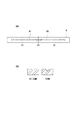
図14は、上記した局所的な摩耗状態を模式的に示したものである。1つの被駆動体5の同一面上に不図示の2つの振動子の接触部が加圧接触されている例を用いて説明する。図14(a)では、被駆動体5における2つの振動子各々との摺動領域をハッチングで表わし、摺動領域A1,A2として示している。摺動領域A1,A2は被駆動体5の略中央付近で重なっている。振動型駆動装置の駆動により生じる被駆動体5の摩耗状態の断面模式図を図14(b)に示す。摺動領域A1のみの箇所での断面をC1、摺動領域A2のみの箇所での断面をC2、摺動領域A1,A2が重なる位置での断面をC3としている。C1,C2部はそれぞれ1つの振動子と摩擦接触するのに対して、C3部は2つの振動子と摩擦接触することになる。このためC3部はC1,C2部と比較すると略2倍の摩耗が生じる。C3部が限界まで摩耗すると振動型駆動装置は寿命に達してしまう。
FIG. 14 schematically shows the above-described local wear state. Description will be made using an example in which the contact portions of two vibrators (not shown) are in pressure contact on the same surface of one driven
よって、本発明は、複数の振動子を用いた場合に、被駆動体の摺動領域における摩耗量の増加を避け、振動型駆動装置の動作寿命の低下を抑制することを目的とする。 Accordingly, an object of the present invention is to avoid an increase in the amount of wear in the sliding region of the driven body and to suppress a decrease in the operating life of the vibration type driving device when a plurality of vibrators are used.
本発明の振動型駆動装置は、異なる振動モードの振動を組み合わせることにより接触部が楕円運動を行う複数の振動子と、前記接触部に接触する摺動領域を有し前記複数の振動子と相対移動する被駆動体と、を備える振動型駆動装置であって、前記複数の振動子は、前記被駆動体の相対移動する方向の異なる位置で、且つ前記相対移動する方向と直交する方向の異なる位置、に夫々配置されることで、前記振動子毎の摺動領域が互いに重ならないように駆動されることを特徴とする。 The vibration type driving device according to the present invention includes a plurality of vibrators in which the contact portion performs an elliptical motion by combining vibrations of different vibration modes, and a sliding region that contacts the contact portion, and is relative to the plurality of vibrators. A plurality of vibrators at different positions in the relative movement direction of the driven bodies and in different directions orthogonal to the relative movement direction. By being arranged at each of the positions, the sliding regions of the vibrators are driven so as not to overlap each other.
複数の振動子を用いた場合に、被駆動体の摺動領域の摩耗が進むことを避け、振動型駆動装置の寿命低下を抑制することができる。 When a plurality of vibrators are used, it is possible to avoid the wear of the sliding region of the driven body from progressing and to suppress the life reduction of the vibration type driving device.
以下、本発明の実施形態について図面を参照しながら詳述する。 Hereinafter, embodiments of the present invention will be described in detail with reference to the drawings.
(実施形態1)
本実施形態では、連続的な回転駆動動作ではなく、所望の回転角度の往復動作が必要な機器へ適用される振動型駆動装置について説明する。例えばレンズ駆動機構における円筒形状回転カムの回転動作によるレンズの直動機構や、回転動作による絞りの駆動等に用いられる。
(Embodiment 1)
In the present embodiment, a vibration type driving device applied to a device that requires a reciprocating operation at a desired rotation angle instead of a continuous rotational driving operation will be described. For example, the lens driving mechanism is used for a linear movement mechanism of a lens by a rotating operation of a cylindrical rotary cam, a diaphragm driving by a rotating operation, and the like.
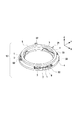
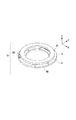
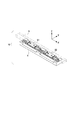
図1は、本発明の実施形態1における振動型駆動装置10の主要部の構成を示す斜視図である。図1の振動型駆動装置10は、3個の振動子ユニットS1,S2,S3と、振動子ユニットを保持する保持部材4と、振動子ユニットS1,S2,S3に対して加圧接触状態で保持される被駆動体5とを備える。振動子ユニットS1,S2,S3は全て同一の形状であり、振動子ユニットは振動子1と振動子1を保持部材に連結する連結部材3とで構成される。振動子1は、被駆動体5との接触部として2つの突起部を有する板状の弾性体からなる振動板6と、振動板6に接合した略矩形形状の電気−機械エネルギー変換素子7とを備える。また、振動子1には、電気−機械エネルギー変換素子7と外部との電気的な接続を行う不図示のフレキシブルプリント基板が設けられている。電気−機械エネルギー変換素子としては、圧電素子や電歪素子と呼ばれる素子を用いることができる。
FIG. 1 is a perspective view showing a configuration of a main part of a vibration
ここで、図3を用いて本実施形態の振動子1に励起される2つの振動モード(形状)の振動について説明する。本実施形態では、振動子1の電気−機械エネルギー変換素子7に交流電圧を印加して振動子1に2つの面外曲げ振動モード(MODE−AとMODE−B)を励振する。MODE−Aは、振動子1の長手方向である図中X軸方向に平行に2つの節が現れる一次の面外曲げ振動モードである。MODE−Aの振動により、突起部2−1、2−2には、被駆動体と接触する面と垂直な方向(Z軸方向)に変位する振幅が励起される。MODE−Bは振動子1の図中Y軸方向に略平行に3つの節が現れる二次の面外曲げ振動モードである。MODE−Bの振動によって、突起部2−1、2−2には、被駆動体と接触する面と平行な方向(X軸方向)に変位する振幅が励起される。
Here, the vibrations of the two vibration modes (shapes) excited by the
これら二つの振動モードを組み合わせることで接触部である突起部2−1,2−2の上面に略XZ面内の楕円運動が発生し、X軸方向に略一致する方向に被駆動体を相対移動させる力が発生する。ただし、本発明は上記した振動子の構成に限定されず、他の面外曲げ振動モードの振動を励起する振動子でも良く、また、図15に示すような他の振動モードを励起する構成の振動子を用いても良い。図15(a)に示す振動子1は略直方体形状であり、振動子1には、図15(b)に示すように、X軸方向に伸縮する一次の伸縮振動モード(MODE−A)と、Y軸方向に略平行に3つの節が現れる二次の面外曲げ振動モード(MODE−B)と、が励起される。この2つの異なる振動モードの重ね合わせにより、突起部2−1,2−2の上面に略XZ面内の楕円振動が生成される。よって、このように図15の振動子を動作させることで、図3に示した振動子と同様に本発明に適用することができる。
By combining these two vibration modes, an elliptical motion in a substantially XZ plane is generated on the upper surfaces of the projecting portions 2-1 and 2-2 which are contact portions, and the driven body is relatively moved in a direction substantially coinciding with the X-axis direction. A moving force is generated. However, the present invention is not limited to the structure of the vibrator described above, and may be a vibrator that excites vibrations in other out-of-plane bending vibration modes, or has a structure that excites other vibration modes as shown in FIG. A vibrator may be used. The
図1に戻り、本実施形態の振動型駆動装置の構成について説明する。連結部材3は保持部材4に対して振動子1を所望の位置に固定する用途を成す。被駆動体5は円環状に形成されており、図中下部の底面側はXY面に平行となるようにフラットに形成されている。この底面が振動子1と接触する。被駆動体5は円環状の中心軸(以下、中心軸)回りに回転可能となるように、不図示のガイド部材で他の軸回りや直線移動が規制されている。
Returning to FIG. 1, the configuration of the vibration type driving device of the present embodiment will be described. The connecting
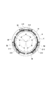
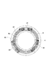
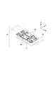
図2に示すように、3個の振動子ユニットS1,S2,S3は中心軸に対して略同心円上で、且つ円周を略3等分する位置に配置される。各振動子ユニットS1,S2,S3は、被駆動体5との接触面を有する突起部2−1,2−2の上面がXY面に平行となるように保持部材4に固定される。
As shown in FIG. 2, the three transducer units S1, S2, and S3 are arranged on a substantially concentric circle with respect to the central axis and at a position that divides the circumference into approximately three equal parts. Each transducer unit S1, S2, S3 is fixed to the holding member 4 so that the upper surfaces of the projecting portions 2-1, 2-2 having contact surfaces with the driven
また、本実施形態においては、振動子ユニットS1,S2,S3と被駆動体5との相対移動量を規定するため機械的に動作範囲を制限する制限部材を設けている。具体的には、保持部材4の外周側に2箇所の回り止め22が形成され、被駆動体5には突起21が形成されている。突起21は回り止め22で挟まれる範囲内で移動可能となっている。つまり、回り止め22と突起21とが被駆動体の相対移動の範囲を機械的に制限する制限部材として機能する。
In the present embodiment, a limiting member that mechanically limits the operating range is provided in order to define the relative movement amount of the transducer units S1, S2, S3 and the driven
図2において、振動子ユニットS1,S2,S3の位置や形状が明示できるように被駆動体5は輪郭のみを鎖線で表わしている。各振動子と接触する被駆動体5の摺動領域は、各振動子ユニットS1,S2,S3に対応して、摺動領域A1,A2,A3として図2中ハッチングで表わす。本実施形態においては、摺動領域A1,A2,A3が重ならず各々円周方向に独立した(円周方向に位置が異なった)摺動領域となるように、振動子ユニットS1,S2,S3と被駆動体5との相対移動量θ(回転角度)が規定されている。
In FIG. 2, only the contour of the driven
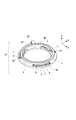
ただし、本発明は、制限部材のような機械的な構造で相対移動量θを制限する形態に限定されない。本実施形態の変形例としては、例えば、回転量を検出することにより得られる検出信号に応じて相対位置を規定する構成が考えられる。図4は、相対移動量θを電気的に検出する検出部材を備えた振動型駆動装置の例(実施形態1の変形例)を示した模式図である。図4においては、被駆動体5の上面側に被駆動体5と離間して光学式エンコーダの検出ヘッド23が配置され、この検出ヘッドと対向して被駆動体5の上面に光学式エンコーダのスケール24が配されている。検出ヘッド23は保持部材4の外周側から延出する光学ヘッド保持部25により固定されている。本変形例では、検出部材である光学式エンコーダの検出信号から被駆動体5の相対位置情報が得られ、この相対位置情報に基づき被駆動体5の相対移動の範囲を規定し、摺動領域が重ならないよう制御すると良い。相対位置情報を得るための検出部材は上記以外にも磁気方式等、任意の方式や形態のものを選択可能である。
However, the present invention is not limited to a form in which the relative movement amount θ is limited by a mechanical structure such as a limiting member. As a modification of the present embodiment, for example, a configuration in which the relative position is defined according to a detection signal obtained by detecting the rotation amount is conceivable. FIG. 4 is a schematic diagram illustrating an example of a vibration type drive device (a modification of the first embodiment) including a detection member that electrically detects the relative movement amount θ. In FIG. 4, a
以上、説明したように本実施形態においては、振動子毎の摺動領域A1,A2,A3が重ならならずに位置が異なるよう、相対移動の範囲を規制することで、摺動領域A1,A2,A3の各領域は摩耗が略均等に生じる。摺動領域A1,A2,A3の夫々が一部重なっている場合と比較して、略2倍の駆動寿命を得ることができる。本実施形態の振動型駆動装置を用いる機構においては、摺動領域が重ならないよう所望の相対移動量θに基づいて設計を行えばよい。また、上記した振動型駆動装置10では振動子ユニットを3個としていたが、本発明において、個数はこれに限定する必要はない。必要なトルク等に応じて振動子ユニットは2個以上の任意の個数を用いることができる。
As described above, in the present embodiment, the sliding areas A1, A2, A3 are not overlapped and the relative movement ranges are restricted so that the sliding areas A1, A2, A3 are different from each other. In each of the areas A2 and A3, wear occurs substantially evenly. Compared with the case where each of the sliding areas A1, A2, and A3 partially overlaps, it is possible to obtain approximately twice the driving life. In the mechanism using the vibration type driving device of the present embodiment, the design may be performed based on the desired relative movement amount θ so that the sliding regions do not overlap. Further, in the above-described vibration
(実施形態2)
本実施形態では、連続的な回転駆動用に適用される振動型駆動装置について説明する。図5は、本発明の実施形態2における振動型駆動装置10の主要部の構成を示す斜視図である。図1に示した実施形態1における振動型駆動装置と同様の箇所の説明は略し、異なる箇所のみを説明する。図6は、図5に示す振動型駆動装置10の平面図であり、振動子ユニットS1,S2,S3の位置や形状が理解できるように被駆動体5は輪郭のみを鎖線で表わしている。被駆動体5における摺動領域は各振動子ユニットS1,S2,S3に対応してA1,A2,A3で表わしている。振動子ユニットS1,S2,S3は円周を略3等分する位置であり、中心軸から各振動子の突起部までの距離が各々異なる値となるように保持部材4上に配置される。つまり、振動子毎の摺動領域は重ならないよう半径方向に夫々位置が異なっており、中心軸から各振動子の突起部までの距離は、摺動領域A1,A2,A3が互いに重ならない値が選択される。
(Embodiment 2)
In the present embodiment, a vibration type driving device applied for continuous rotational driving will be described. FIG. 5 is a perspective view illustrating a configuration of a main part of the vibration
よって、本実施形態においては、摺動領域A1,A2,A3が互いに重ならずに位置が異なっているため、各摺動領域は摩耗が略均等に生じる。3つの摺動領域A1,A2,A3が重なるように振動子ユニットS1,S2,S3が配置されている状態と比較すると、被駆動体5の摺動領域の摩耗量は略1/3となり、動作寿命の向上する。また、実施形態1と同様に、振動子ユニットの個数は3個に限定する必要はない。必要なトルク等に応じて振動子ユニットは2個以上の任意の個数を用いれば良い。更に、図6において、振動子ユニットS1,S2,S3は円周を略3等分する位置に配置したが、本実施形態において振動子ユニットの円周方向における位置はこれに限定されず、任意の位置に配置すると良い。
Therefore, in the present embodiment, the sliding regions A1, A2, and A3 do not overlap each other and have different positions, so that the sliding regions are substantially evenly worn. Compared with the state in which the vibrator units S1, S2, S3 are arranged so that the three sliding areas A1, A2, A3 overlap, the wear amount of the sliding area of the driven
(実施形態3)
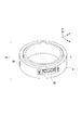
本実施形態の振動型駆動装置は、実施形態1、2と異なり、振動子が被駆動体の側面に配置される。図7は、本発明の実施形態3における振動型駆動装置10の構成を概略的に示す斜視図である。本実施形態において被駆動体5は略円筒形状であり、被駆動体5の摺動領域は外周側の側面に形成される。被駆動体5は保持部材4に対して円筒形状の中心軸回りに相対的に回転可能に保持されており、他の軸回りや並進移動は拘束されている。
(Embodiment 3)
Unlike the first and second embodiments, the vibratory drive device according to the present embodiment has a vibrator disposed on the side surface of the driven body. FIG. 7 is a perspective view schematically showing the configuration of the vibration
振動子ユニットS1,S2,S3は被駆動体5との接触部となる突起部の上面が被駆動体5の外周側面に接するように保持部材4に固定される。振動子の構成は実施形態1、2と同様である。図8は、図7に示す振動型駆動装置10の側面図であり、振動子ユニットS1,S2,S3の配置箇所及び被駆動体5の摺動領域A1,A2,A3が確認できるように、保持部材4を除去して図示している。被駆動体5における摺動領域は、各振動子ユニットS1,S2,S3に対応してA1,A2,A3で表わしている。
The
振動子ユニットS1,S2,S3は、円周を略3等分する位置であり、被駆動体5の円筒形状の中心軸方向(図中Z方向であり回転軸方向と同義)に各々異なる位置となるように配置される。この中心軸方向における位置は、図8に示すように被駆動体5における摺動領域A1,A2,A3が互いに重ならない値が選択されている。つまり、本実施形態において、振動子毎の摺動領域が重ならないよう回転軸方向に夫々位置が異なっているため、各摺動領域は摩擦が略均等に生じる。また、実施形態1、2と同様に、振動子ユニットの個数は3個に限定する必要はない。必要なトルク等に応じて振動子ユニットは2個以上の任意の個数を用いれば良い。更に、振動子ユニットS1,S2,S3は円周を略3等分する位置に配置したが、本実施形態において振動子ユニットの円周方向における位置はこれに限定されず、任意の位置に配置すると良い。
The vibrator units S1, S2, and S3 are positions that divide the circumference into approximately three equal parts, and positions that are different from each other in the cylindrical central axis direction of the driven body 5 (the Z direction in the figure and synonymous with the rotation axis direction) It arrange | positions so that it may become. As the position in the central axis direction, a value is selected so that the sliding areas A1, A2, A3 in the driven
(実施形態4)
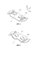
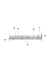
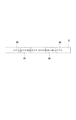
本実施形態では、実施形態1〜3と異なり、複数の振動子に対して被駆動体を相対的に直線移動(並進運動)させる形態について説明する。図9は、実施形態4における振動型駆動装置10の主要部の構成を示す斜視図である。2つの振動子ユニットS1,S2は図中X方向(直線移動の方向)に略一列に並べて配置され、保持部材4に固定されている。振動子の構成は実施形態1〜3と同じである。本実施形態において被駆動体5は略直方体形状であり、X方向に延びている。被駆動体5は振動子ユニットS1,S2に対してX方向に相対移動する。被駆動体5はX方向の並進自由度のみが生じるように不図示のガイドで保持されている。
(Embodiment 4)
In the present embodiment, unlike
図10は、図9に示す振動型駆動装置10の平面図であり、被駆動体5と振動子ユニットS1,S2の位置関係が確認できるように図示している。2つの振動子ユニットS1,S2のX方向の間隔は、必要なストロークの直線移動を行ったときに摺動領域A1,A2が重ならないように決められている。各摺動領域が重ならないよう、振動子毎に位置を異ならせる方法は、実施形態1で示したように、被駆動体の相対移動量を制限する制限部材を設けてもよい。また、検出部材により被駆動体の相対位置情報を取得して相対移動の範囲を規定しても良い。
FIG. 10 is a plan view of the vibration
以上説明したように、本実施形態においては、各摺動領域は振動子毎に直線移動の方向に位置が異なり互いに重ならないため、各摺動領域は摩耗が略均等に生じる。また、振動子ユニットの個数は2個に限定する必要はない。必要なトルク等に応じて振動子ユニットは2個以上の任意の個数を用いれば良い。 As described above, in the present embodiment, the sliding regions have different positions in the direction of linear movement for each transducer and do not overlap with each other. Further, the number of vibrator units need not be limited to two. Any number of vibrator units may be used in accordance with the required torque or the like.
(実施形態5)
本実施形態では、実施形態4と同様に、複数の振動子に対して被駆動体を相対的に直線移動させる形態について説明する。実施形態4とは、直線移動と垂直な方向における振動体ユニットの配置位置が異なる。
(Embodiment 5)
In the present embodiment, as in the fourth embodiment, a mode in which the driven body is linearly moved relative to the plurality of vibrators will be described. The arrangement position of the vibrating body unit in the direction perpendicular to the linear movement is different from that of the fourth embodiment.
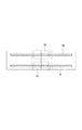
図11は、実施形態5における振動型駆動装置10の構成を概略的に示す斜視図である。図12は、図11に示す振動型駆動装置10の平面図であり、被駆動体5と振動子ユニットS1,S2の位置関係が確認できるように図示している。本実施形態において被駆動体5は、2つの振動子ユニットS1,S2に対してX方向に相対的に直線移動する。振動子ユニットS1とS2はY方向(直線移動と垂直な方向)に並べて保持部材4上に配置される。被駆動体5は、Y方向に並んだ2つの振動子ユニットS1,S2と接触する摺動領域が確保できるX,Y方向寸法を持つよう直方体形状に形成される。
FIG. 11 is a perspective view schematically showing a configuration of the vibration
このように振動子ユニットを配置することで、被駆動体5における2つの摺動領域A1,A2は位置が異なり互いに重ならないため、各摺動領域は摩耗が略均等に生じる。また、振動子ユニットの個数は2個に限定する必要はない。必要なトルク等に応じて振動子ユニットは2個以上の任意の個数を用いれば良い。更に、図12では、2つの振動子ユニットS1,S2はY方向に並べて配置したが、摺動領域A1,A2が重ならなければ、上記形態に限定されない。例えば、図13に示すように振動子ユニットS1,S2を直線移動方向及び直線移動と垂直な方向にずらして配置しても良い。図13のように配置することで、直線移動と直交する方向の被駆動体の寸法を抑えることができる。
By arranging the vibrator unit in this manner, the two sliding areas A1 and A2 in the driven
1 振動子
3 連結部材
4 保持部材
5 被駆動体
6 振動板
7 電気−機械エネルギー変換素子
10 振動型駆動装置
S1,S2,S3 振動子ユニット
DESCRIPTION OF
Claims (5)
前記複数の振動子は、前記被駆動体の相対移動する方向の異なる位置で、且つ前記相対移動する方向と直交する方向の異なる位置、に夫々配置されることで、前記振動子毎の摺動領域が互いに重ならないように駆動されることを特徴とする振動型駆動装置。 A plurality of vibrators in which the contact portion performs elliptical motion by combining vibrations of different vibration modes; and a driven body that has a sliding region that contacts the contact portion and moves relative to the plurality of vibrators. A vibration type drive device,
The plurality of vibrators are arranged at different positions in the relative movement direction of the driven body and at different positions in a direction orthogonal to the relative movement direction, so that sliding for each vibrator is performed. A vibration type driving apparatus, wherein the driving is performed so that the regions do not overlap each other.
Priority Applications (3)
| Application Number | Priority Date | Filing Date | Title |
|---|---|---|---|
| JP2010135500A JP5791237B2 (en) | 2010-06-14 | 2010-06-14 | Vibration type driving device |
| US13/158,255 US8704426B2 (en) | 2010-06-14 | 2011-06-10 | Vibration-type driving device |
| US14/174,758 US9871468B2 (en) | 2010-06-14 | 2014-02-06 | Vibration-type driving device |
Applications Claiming Priority (1)
| Application Number | Priority Date | Filing Date | Title |
|---|---|---|---|
| JP2010135500A JP5791237B2 (en) | 2010-06-14 | 2010-06-14 | Vibration type driving device |
Publications (2)
| Publication Number | Publication Date |
|---|---|
| JP2012005183A JP2012005183A (en) | 2012-01-05 |
| JP5791237B2 true JP5791237B2 (en) | 2015-10-07 |
Family
ID=45095671
Family Applications (1)
| Application Number | Title | Priority Date | Filing Date |
|---|---|---|---|
| JP2010135500A Active JP5791237B2 (en) | 2010-06-14 | 2010-06-14 | Vibration type driving device |
Country Status (2)
| Country | Link |
|---|---|
| US (2) | US8704426B2 (en) |
| JP (1) | JP5791237B2 (en) |
Families Citing this family (4)
| Publication number | Priority date | Publication date | Assignee | Title |
|---|---|---|---|---|
| JP5773900B2 (en) * | 2012-01-30 | 2015-09-02 | キヤノン株式会社 | motor |
| JP2014018027A (en) * | 2012-07-11 | 2014-01-30 | Canon Inc | Vibration type actuator, imaging apparatus, and stage |
| JP2017073890A (en) * | 2015-10-07 | 2017-04-13 | キヤノン株式会社 | Translation drive device, image blur correction device, lens barrel, and imaging device |
| JP2018074723A (en) * | 2016-10-27 | 2018-05-10 | セイコーエプソン株式会社 | Drive device, piezoelectric motor, robot, electronic component transfer device and printer |
Family Cites Families (17)
| Publication number | Priority date | Publication date | Assignee | Title |
|---|---|---|---|---|
| JPS6122778A (en) | 1984-07-10 | 1986-01-31 | Matsushita Electric Ind Co Ltd | piezoelectric motor |
| JPS63253882A (en) | 1987-04-10 | 1988-10-20 | Citizen Watch Co Ltd | Progressive wave step motor |
| JP2556045B2 (en) | 1987-07-22 | 1996-11-20 | アイシン精機株式会社 | Ultrasonic motor |
| JPH02146971A (en) * | 1988-11-28 | 1990-06-06 | Hitachi Ltd | Piezoelectric motor and piezoelectric motor driving method |
| JPH05211786A (en) | 1992-01-30 | 1993-08-20 | Toyoda Mach Works Ltd | Ultrasonic motor |
| JP3807513B2 (en) * | 1996-02-05 | 2006-08-09 | オリンパス株式会社 | Ultrasonic linear motor |
| JP4688245B2 (en) * | 1998-06-02 | 2011-05-25 | セイコーインスツル株式会社 | Electronic system with positioning system and ultrasonic motor |
| JP2001086777A (en) * | 1999-09-17 | 2001-03-30 | Nikon Corp | Vibration actuator device |
| JP4236957B2 (en) * | 2002-03-11 | 2009-03-11 | セイコーインスツル株式会社 | Ultrasonic motor and electronic device with ultrasonic motor |
| JP4576154B2 (en) * | 2004-05-13 | 2010-11-04 | オリンパス株式会社 | Ultrasonic motor |
| JP4689993B2 (en) * | 2004-09-07 | 2011-06-01 | オリンパス株式会社 | Vibration wave motor |
| JP4395052B2 (en) * | 2004-11-10 | 2010-01-06 | 太陽誘電株式会社 | Drive device |
| JP4576214B2 (en) * | 2004-11-26 | 2010-11-04 | オリンパスイメージング株式会社 | Ultrasonic motor and lens barrel |
| JP2007074829A (en) * | 2005-09-07 | 2007-03-22 | Konica Minolta Opto Inc | Vibration actuator |
| WO2008152820A1 (en) | 2007-06-14 | 2008-12-18 | Panasonic Corporation | Oscillation type actuator and drive device using the same |
| JP2009142014A (en) * | 2007-12-04 | 2009-06-25 | Olympus Corp | Ultrasonic motor |
| JP2009165221A (en) * | 2007-12-28 | 2009-07-23 | Konica Minolta Opto Inc | Friction drive actuator, and hard disk device using the same |
-
2010
- 2010-06-14 JP JP2010135500A patent/JP5791237B2/en active Active
-
2011
- 2011-06-10 US US13/158,255 patent/US8704426B2/en not_active Expired - Fee Related
-
2014
- 2014-02-06 US US14/174,758 patent/US9871468B2/en active Active
Also Published As
| Publication number | Publication date |
|---|---|
| JP2012005183A (en) | 2012-01-05 |
| US9871468B2 (en) | 2018-01-16 |
| US20140152149A1 (en) | 2014-06-05 |
| US20110304242A1 (en) | 2011-12-15 |
| US8704426B2 (en) | 2014-04-22 |
Similar Documents
| Publication | Publication Date | Title |
|---|---|---|
| JP6056224B2 (en) | Vibration wave motor | |
| JP5791237B2 (en) | Vibration type driving device | |
| JP2014018027A (en) | Vibration type actuator, imaging apparatus, and stage | |
| JP5256762B2 (en) | Lens barrel, camera | |
| JP2014236522A (en) | Vibration type actuator and optical device | |
| JP4035157B2 (en) | Ultrasonic actuator | |
| KR101045996B1 (en) | Piezoelectric linear motor | |
| KR101053805B1 (en) | Vibrating actuator | |
| JP5353881B2 (en) | Ultrasonic actuator | |
| JP5459192B2 (en) | Vibration wave motor, lens barrel and camera | |
| JP2004274916A (en) | Actuator | |
| JP5668683B2 (en) | Piezoelectric actuator, lens barrel and camera | |
| JP2007306799A (en) | Ultrasonic actuator | |
| JP5541281B2 (en) | Vibration actuator, lens barrel and camera | |
| JP2010124603A (en) | Drive unit and drive method | |
| JP7272177B2 (en) | Piezo drives and robots | |
| JP5483845B2 (en) | Vibration wave motor | |
| JP4654884B2 (en) | Multi-degree-of-freedom ultrasonic motor | |
| KR20110107414A (en) | Piezoelectric ultrasonic motor | |
| JP2008072785A (en) | Vibration type linear drive device and camera lens | |
| JP2010166720A (en) | Drive unit of ultrasonic motor | |
| JP4979017B2 (en) | Ultrasonic motor and ultrasonic vibrator used therefor | |
| US12088220B2 (en) | Vibrating actuator, multi-axis stage, articulated robot, and continuum robot | |
| JP5736646B2 (en) | Vibration wave motor, lens barrel and camera | |
| JP2010166722A (en) | Drive unit of ultrasonic motor |
Legal Events
| Date | Code | Title | Description |
|---|---|---|---|
| A621 | Written request for application examination |
Free format text: JAPANESE INTERMEDIATE CODE: A621 Effective date: 20130614 |
|
| A977 | Report on retrieval |
Free format text: JAPANESE INTERMEDIATE CODE: A971007 Effective date: 20140326 |
|
| A131 | Notification of reasons for refusal |
Free format text: JAPANESE INTERMEDIATE CODE: A131 Effective date: 20140415 |
|
| A521 | Request for written amendment filed |
Free format text: JAPANESE INTERMEDIATE CODE: A523 Effective date: 20140613 |
|
| A131 | Notification of reasons for refusal |
Free format text: JAPANESE INTERMEDIATE CODE: A131 Effective date: 20150203 |
|
| A521 | Request for written amendment filed |
Free format text: JAPANESE INTERMEDIATE CODE: A523 Effective date: 20150406 |
|
| TRDD | Decision of grant or rejection written | ||
| A01 | Written decision to grant a patent or to grant a registration (utility model) |
Free format text: JAPANESE INTERMEDIATE CODE: A01 Effective date: 20150707 |
|
| A61 | First payment of annual fees (during grant procedure) |
Free format text: JAPANESE INTERMEDIATE CODE: A61 Effective date: 20150804 |
|
| R151 | Written notification of patent or utility model registration |
Ref document number: 5791237 Country of ref document: JP Free format text: JAPANESE INTERMEDIATE CODE: R151 |