JP5791224B2 - Game machine - Google Patents

Game machine Download PDF

Info

Publication number
JP5791224B2
JP5791224B2 JP2009228707A JP2009228707A JP5791224B2 JP 5791224 B2 JP5791224 B2 JP 5791224B2 JP 2009228707 A JP2009228707 A JP 2009228707A JP 2009228707 A JP2009228707 A JP 2009228707A JP 5791224 B2 JP5791224 B2 JP 5791224B2
Authority
JP
Japan
Prior art keywords
lever
lever member
pressed
gaming machine
terminal
Prior art date
Legal status (The legal status is an assumption and is not a legal conclusion. Google has not performed a legal analysis and makes no representation as to the accuracy of the status listed.)
Active
Application number
JP2009228707A
Other languages
Japanese (ja)
Other versions
JP2011072668A5 (en
JP2011072668A (en
Inventor
澤田 盛弘
盛弘 澤田
Current Assignee (The listed assignees may be inaccurate. Google has not performed a legal analysis and makes no representation or warranty as to the accuracy of the list.)
Sanyo Bussan Co Ltd
Original Assignee
Sanyo Bussan Co Ltd
Priority date (The priority date is an assumption and is not a legal conclusion. Google has not performed a legal analysis and makes no representation as to the accuracy of the date listed.)
Filing date
Publication date
Application filed by Sanyo Bussan Co Ltd filed Critical Sanyo Bussan Co Ltd
Priority to JP2009228707A priority Critical patent/JP5791224B2/en
Publication of JP2011072668A publication Critical patent/JP2011072668A/en
Publication of JP2011072668A5 publication Critical patent/JP2011072668A5/ja
Application granted granted Critical
Publication of JP5791224B2 publication Critical patent/JP5791224B2/en
Active legal-status Critical Current
Anticipated expiration legal-status Critical

Links

Images

Description

本発明は、パチンコ機等に代表される遊技機に関するものである。   The present invention relates to a gaming machine represented by a pachinko machine or the like.

従来より、パチンコ機やスロットマシン等の遊技機は、複数の外部接続用端子を有する接続装置が設けられている。例えば、この接続装置の各外部接続用端子には、管理装置に通じる配線がそれぞれ接続可能であり、それら各配線を介して遊技に関する情報が遊技機から管理装置へ送信されることで、管理装置側で遊技機の状況を管理することができるように構成されている。 Conventionally, the pachinko machine or a gaming machine such as a slot machine, the connection device is provided with a terminal plurality of external connection. For example, each external connection terminals of the connection device, the wiring leading to the management device or the like are possible respectively connected, by the information regarding the game via their respective lines are sent from the gaming machine to the management device or the like, It is configured such that the state of the gaming machine can be managed on the management device side or the like.

特開平11−076511号公報Japanese Patent Application Laid-Open No. 11-075511

ここで、上記例示した接続装置等の接続手段において好適な構造が求められている。Here, there is a demand for a suitable structure in the connection means such as the connection device exemplified above.

本発明は、上記例示した問題点等を解決するためになされたものであり、好適な構造を有する接続手段を備えた遊技機を提供することを目的としている。 The present invention has been made to solve the above-described problems and the like, and an object thereof is to provide a gaming machine provided with connection means having a suitable structure .

この目的を達成するために、請求項1記載の遊技機は、遊技情報を外部に出力するための配線が接続される接続手段を備え、前記接続手段は、前記配線が挿入される挿入口を有するケースと、その挿入口に対応するよう設けられる端子部と、押圧操作可能なレバーと、そのレバーの所定部位を前記端子部側へ付勢するための付勢手段とを備え、前記レバーが押圧操作されることで、前記所定部位が前記端子部から離間する側へ移動される一方、そのレバーの押圧操作が解除されることで、前記付勢手段の付勢により前記所定部位が前記端子部側へ移動され、前記ケースは、前記挿入口が設けられる上面部と、その上面部に対向配置される底面部とを少なくとも備え、前記レバーは、第2操作部を有する第2レバーと、その第2レバーの一方の隣に設けられ、一方側第1操作部を有する一方側第1レバーと、前記第2レバーの他方の隣に設けられ、他方側第1操作部を有する他方側第1レバーとを少なくとも含み、押圧操作されていない場合の前記第2操作部は、押圧操作されていない場合の前記一方側第1操作部および前記他方側第1操作部よりも前記底面部から離れた位置に位置し、特定の押下位置まで押圧操作された場合の前記第2操作部の先端は、前記接続手段を上面視した場合の前記第2操作部の押圧操作によって該第2操作部の先端の位置が変位する方向において、押圧操作されていない場合の前記一方側第1操作部および前記他方側第1操作部の先端よりも前記ケースから外方に位置するものである。
In order to achieve this object, the gaming machine according to claim 1 includes connection means to which wiring for outputting game information to the outside is connected, and the connection means has an insertion port into which the wiring is inserted. A case having a terminal, a terminal provided to correspond to the insertion port, a lever capable of pressing, and a biasing means for biasing a predetermined portion of the lever toward the terminal. When the pressing operation is performed, the predetermined portion is moved to the side away from the terminal portion, and when the pressing operation of the lever is released, the predetermined portion is moved to the terminal by the biasing of the biasing means. The case is provided with at least a top surface portion on which the insertion port is provided and a bottom surface portion disposed to face the top surface portion, and the lever includes a second lever having a second operation portion; One of its second levers Provided, whereas the one-side first lever having a first operating portion side, provided on the other next to the second lever, at least and a second side first lever having a first operation portion the other side, pressing The second operation portion when not operated is located at a position farther from the bottom surface than the first operation portion on the one side and the first operation portion on the other side when the operation is not performed. The tip of the second operation unit when the pressing operation is performed to the pressed position is in a direction in which the position of the tip of the second operation unit is displaced by the pressing operation of the second operation unit when the connection means is viewed from above. , but also from the one first operating unit side and the first operation portion the other side tip when not depressed located outwardly from the case.

請求項2記載の遊技機は、遊技情報を外部に出力するための配線が接続される接続手段を備え、前記接続手段は、前記配線が挿入される挿入口を有するケースと、その挿入口に対応するよう設けられる端子部と、押圧操作可能なレバーと、そのレバーの所定部位を前記端子部側へ付勢するための付勢手段とを備え、前記レバーが押圧操作されることで、前記所定部位が前記端子部から離間する側へ移動される一方、そのレバーの押圧操作が解除されることで、前記付勢手段の付勢により前記所定部位が前記端子部側へ移動され、前記ケースは、前記挿入口が設けられる上面部と、その上面部に対向配置される底面部とを少なくとも備え、前記レバーは、第2操作部を有する第2レバーと、その第2レバーの一方の隣に設けられ、一方側第1操作部を有する一方側第1レバーと、前記第2レバーの他方の隣に設けられ、他方側第1操作部を有する他方側第1レバーとを少なくとも含み、押圧操作されていない場合の前記第2操作部は、押圧操作されていない場合の前記一方側第1操作部および前記他方側第1操作部よりも前記底面部から離れた位置に位置し、特定の押下位置まで押圧操作された場合の前記第2操作部の先端は、前記所定部位が前記端子部から離間する方向において、押圧操作されていない場合の前記一方側第1操作部および前記他方側第1操作部の先端よりも前記ケースから外方に位置するものである。
The gaming machine according to claim 2 includes a connection unit to which a wiring for outputting game information to the outside is connected, and the connection unit includes a case having an insertion port into which the wiring is inserted, and an insertion port of the case. A correspondingly provided terminal portion, a lever capable of being pressed, and a biasing means for biasing a predetermined portion of the lever toward the terminal portion, the lever being pressed, While the predetermined portion is moved to the side away from the terminal portion, the pressing operation of the lever is released, so that the predetermined portion is moved to the terminal portion side by the biasing of the biasing means, and the case Comprises at least a top surface provided with the insertion port and a bottom surface disposed opposite to the top surface. The lever includes a second lever having a second operating portion and one of the second levers. provided on one side first steering A one-side first lever having a part, provided on the other next to the second lever, at least and a second side first lever having a first operation portion the other side, the second if not pressed The operation unit is located at a position farther from the bottom surface than the first operation unit on the one side and the first operation unit on the other side when the operation is not performed, and when the operation is performed to a specific pressing position. The tip of the second operation part is more in the case than the tips of the first operation part on the one side and the first operation part on the other side when the predetermined part is not pressed in the direction away from the terminal part. It is located outside.

請求項3記載の遊技機は、遊技情報を外部に出力するための配線が接続される接続手段を備え、前記接続手段は、前記遊技機本体の背面側に設けられ、前記配線が挿入される挿入口を有するケースと、その挿入口に対応するよう設けられる端子部と、押圧操作可能なレバーと、そのレバーの所定部位を前記端子部側へ付勢するための付勢手段とを備え、前記レバーが押圧操作されることで、前記所定部位が前記端子部から離間する側へ移動される一方、そのレバーの押圧操作が解除されることで、前記付勢手段の付勢により前記所定部位が前記端子部側へ移動され、前記レバーは、第2操作部を有する第2レバーと、その第2レバーの一方の隣に設けられ、一方側第1操作部を有する一方側第1レバーと、前記第2レバーの他方の隣に設けられ、他方側第1操作部を有する他方側第1レバーとを少なくとも含み、押圧操作されていない場合の前記第2操作部は、押圧操作されていない場合の前記一方側第1操作部および前記他方側第1操作部よりも前記遊技機本体の背面から離れた位置に位置し、特定の押下位置まで押圧操作された場合の前記第2操作部の先端は、前記遊技機を背面視した場合の前記第2操作部の押圧操作によって該第2操作部の先端の位置が変位する方向において、押圧操作されていない場合の前記一方側第1操作部および前記他方側第1操作部の先端よりも前記ケースから外方に位置するものである。
The gaming machine according to claim 3 is provided with a connecting means to which wiring for outputting game information to the outside is connected, and the connecting means is provided on the back side of the gaming machine main body, and the wiring is inserted therein. A case having an insertion port, a terminal portion provided so as to correspond to the insertion port, a lever that can be pressed, and a biasing means for biasing a predetermined portion of the lever toward the terminal portion, When the lever is pressed, the predetermined portion is moved to the side away from the terminal portion, while when the lever is released, the predetermined portion is pressed by the biasing means. Is moved to the terminal portion side, and the lever is provided with a second lever having a second operation portion, and one side first lever having one side first operation portion provided next to one of the second levers. , et al on the other next to the second lever Comprises at least a second side first lever having a first operation portion the other side, the second operating unit when not depressed, the one side first operating portion and the other if not pressed The distal end of the second operation unit when located at a position farther away from the back side of the gaming machine body than the first side operation unit and being pressed to a specific pressing position is obtained when the gaming machine is viewed from the back side. in a direction displacement position of the tip of the second operating portion by the pressing operation of the second operating unit, than the one first operating unit side and the first operation portion the other side tip when not depressed It is located outward from the case.

請求項4記載の遊技機は、遊技情報を外部に出力するための配線が接続される接続手段を備え、前記接続手段は、前記遊技機本体の背面側に設けられ、前記配線が挿入される挿入口を有するケースと、その挿入口に対応するよう設けられる端子部と、押圧操作可能なレバーと、そのレバーの所定部位を前記端子部側へ付勢するための付勢手段とを備え、前記レバーが押圧操作されることで、前記所定部位が前記端子部から離間する側へ移動される一方、そのレバーの押圧操作が解除されることで、前記付勢手段の付勢により前記所定部位が前記端子部側へ移動され、前記レバーは、第2操作部を有する第2レバーと、その第2レバーの一方の隣に設けられ、一方側第1操作部を有する一方側第1レバーと、前記第2レバーの他方の隣に設けられ、他方側第1操作部を有する他方側第1レバーとを少なくとも含み、押圧操作されていない場合の前記第2操作部は、押圧操作されていない場合の前記一方側第1操作部および前記他方側第1操作部よりも前記遊技機本体の背面から離れた位置に位置し、特定の押下位置まで押圧操作された場合の前記第2操作部の先端は、前記所定部位が前記端子部から離間する方向において、押圧操作されていない場合の前記一方側第1操作部および前記他方側第1操作部の先端よりも前記ケースから外方に位置するものである。
The gaming machine according to claim 4 includes connection means to which wiring for outputting game information to the outside is connected, and the connection means is provided on the back side of the gaming machine main body, and the wiring is inserted therein. A case having an insertion port, a terminal portion provided so as to correspond to the insertion port, a lever that can be pressed, and a biasing means for biasing a predetermined portion of the lever toward the terminal portion, When the lever is pressed, the predetermined portion is moved to the side away from the terminal portion, while when the lever is released, the predetermined portion is pressed by the biasing means. Is moved to the terminal portion side, and the lever is provided with a second lever having a second operation portion, and one side first lever having one side first operation portion provided next to one of the second levers. , et al on the other next to the second lever Comprises at least a second side first lever having a first operation portion the other side, the second operating unit when not depressed, the one side first operating portion and the other if not pressed The tip of the second operation unit is located at a position farther away from the back of the gaming machine body than the first operation unit on the side, and the predetermined portion is separated from the terminal unit when the pressing operation is performed to a specific pressing position. in a direction, but also from the one first operating unit side and the first operation portion the other side tip when not depressed located outwardly from the case.

本発明の遊技機によれば、好適な構造を有する接続手段を備えることができるという効果がある。 According to the gaming machine of the present invention, there is an effect that connection means having a suitable structure can be provided .

本発明の一実施の形態におけるパチンコ機の正面図である。It is a front view of the pachinko machine in one embodiment of the present invention. パチンコ機の遊技盤の正面図である。It is a front view of the game board of a pachinko machine. パチンコ機の背面図である。It is a rear view of a pachinko machine. 接続装置の正面図である。It is a front view of a connection device. 接続装置を上面視した上面図である。It is the top view which looked at the connection apparatus from the top . 接続装置の側面図である。It is a side view of a connection device. 図5のVII−VII線における接続装置の断面図である。It is sectional drawing of the connection apparatus in the VII-VII line of FIG. 図5のVIII−VIII線における接続装置の断面図である。It is sectional drawing of the connection apparatus in the VIII-VIII line of FIG. (a)は、端子部材の側面図であり、(b)は、図9(a)の矢印IXb方向から視た端子部材の正面図である。(A) is a side view of a terminal member, (b) is a front view of the terminal member seen from the arrow IXb direction of Fig.9 (a). (a)は、第1レバー部材の正面図であり、(b)は、図10(a)の矢印Xb方向から視た第1レバー部材の側面図である。(A) is a front view of a 1st lever member, (b) is a side view of the 1st lever member seen from the arrow Xb direction of Fig.10 (a). (a)は、第2レバー部材の正面図であり、(b)は、図11(a)の矢印XIb方向から視た第2レバー部材の側面図である。(A) is a front view of a 2nd lever member, (b) is a side view of the 2nd lever member seen from the arrow XIb direction of Fig.11 (a). (a)は、ケース部材の断面図であり、(b)は、図12(a)のXIIb−XIIb線におけるケース部材の断面図である。(A) is sectional drawing of a case member, (b) is sectional drawing of the case member in the XIIb-XIIb line | wire of Fig.12 (a). 接続装置の断面図である。It is sectional drawing of a connection apparatus. 接続装置の断面図である。It is sectional drawing of a connection apparatus. パチンコ機の電気的構成を示すブロック図である。It is a block diagram which shows the electric constitution of a pachinko machine. 第2実施の形態における接続装置の上面図である。It is a top view of the connection apparatus in 2nd Embodiment. 第3実施の形態における接続装置の上面図である。It is a top view of the connecting device in a 3rd embodiment. (a)は、第1レバー部材の正面図であり、(b)は、図18(a)の矢印XVIIIb方向から視た第1レバー部材の側面図である。(A) is a front view of a 1st lever member, (b) is a side view of the 1st lever member seen from the arrow XVIIIb direction of Fig.18 (a). (a)は、第2レバー部材の正面図であり、(b)は、図19(a)の矢印XIXb方向から視た第2レバー部材の側面図である。(A) is a front view of a 2nd lever member, (b) is a side view of the 2nd lever member seen from the arrow XIXb direction of Fig.19 (a).

以下、本発明の好ましい実施の形態について、添付図面を参照して説明する。図1は、本発明の一実施の形態におけるパチンコ遊技機(以下「パチンコ機」と称す)10の正面図であり、図2は、パチンコ機10の遊技盤13の正面図であり、図3は、パチンコ機10の背面図である。   DESCRIPTION OF EXEMPLARY EMBODIMENTS Hereinafter, preferred embodiments of the invention will be described with reference to the accompanying drawings. FIG. 1 is a front view of a pachinko gaming machine (hereinafter referred to as “pachinko machine”) 10 according to an embodiment of the present invention, and FIG. 2 is a front view of a game board 13 of the pachinko machine 10. FIG. 3 is a rear view of the pachinko machine 10.

パチンコ機10は、図1に示すように、略矩形状に組み合わせた木枠により外殻が形成される外枠11と、その外枠11と略同一の外形形状に形成され外枠11に対して開閉可能に支持された内枠12とを備えている。外枠11には、内枠12を支持するために正面視(図1参照)左側の上下2カ所に金属製のヒンジ18が取り付けられ、そのヒンジ18が設けられた側を開閉の軸として内枠12が正面手前側へ開閉可能に支持されている。   As shown in FIG. 1, the pachinko machine 10 includes an outer frame 11 having an outer shell formed of a wooden frame combined in a substantially rectangular shape, and an outer frame 11 having substantially the same outer shape as the outer frame 11. And an inner frame 12 supported to be openable and closable. In order to support the inner frame 12, metal hinges 18 are attached to the outer frame 11 at two upper and lower portions on the left side when viewed from the front (see FIG. 1), and the side on which the hinge 18 is provided is used as an opening / closing axis. The frame 12 is supported so as to be openable and closable to the front front side.

内枠12には、多数の釘や入賞口63,64等を有する遊技盤13(図2参照)が裏面側から着脱可能に装着される。この遊技盤13の前面を球が流下することにより弾球遊技が行われる。なお、内枠12には、球を遊技盤13の前面領域に発射する球発射ユニット(図示せず)やその球発射ユニットから発射された球を遊技盤13の前面領域まで誘導する発射レール(図示せず)等が取り付けられている。   A game board 13 (see FIG. 2) having a large number of nails, winning holes 63, 64, and the like is detachably mounted on the inner frame 12 from the back side. A ball ball game is performed when the ball flows down the front surface of the game board 13. The inner frame 12 has a ball launch unit (not shown) for launching a ball to the front area of the game board 13 and a launch rail (not shown) for guiding the ball launched from the ball launch unit to the front area of the game board 13. Etc.) are attached.

内枠12の前面側には、その前面上側を覆う前面枠14と、その下側を覆う下皿ユニット15とが設けられている。前面枠14及び下皿ユニット15を支持するために正面視(図1参照)左側の上下2カ所に金属製のヒンジ19が取り付けられ、そのヒンジ19が設けられた側を開閉の軸として前面枠14及び下皿ユニット15が正面手前側へ開閉可能に支持されている。なお、内枠12の施錠と前面枠14の施錠とは、シリンダ錠20の鍵穴21に専用の鍵を差し込んで所定の操作を行うことでそれぞれ解除される。   On the front side of the inner frame 12, a front frame 14 that covers the upper side of the front surface and a lower dish unit 15 that covers the lower side of the front frame 14 are provided. In order to support the front frame 14 and the lower dish unit 15, metal hinges 19 are attached to two upper and lower portions on the left side when viewed from the front (see FIG. 1), and the side on which the hinges 19 are provided is used as an opening / closing axis. 14 and the lower pan unit 15 are supported so as to be openable and closable toward the front front side. The locking of the inner frame 12 and the locking of the front frame 14 are respectively released by inserting a dedicated key into the key hole 21 of the cylinder lock 20 and performing a predetermined operation.

前面枠14は、装飾用の樹脂部品や電気部品等を組み付けたものであり、その略中央部には略楕円形状に開口形成された窓部14cが設けられている。前面枠14の裏面側には2枚の板ガラスを有するガラスユニット16が配設され、そのガラスユニット16を介して遊技盤13の前面がパチンコ機10の正面側に視認可能となっている。前面枠14には、球を貯留する上皿17が前方へ張り出して上面を開放した略箱状に形成されており、この上皿17に賞球や貸出球などが排出される。   The front frame 14 is assembled with decorative resin parts, electrical parts, and the like, and a window part 14c that is formed in an approximately elliptical shape is provided at a substantially central part thereof. A glass unit 16 having two plate glasses is disposed on the back side of the front frame 14, and the front surface of the game board 13 can be seen on the front side of the pachinko machine 10 through the glass unit 16. On the front frame 14, an upper plate 17 that stores balls is formed in a substantially box shape that protrudes forward and the upper surface is opened, and prize balls and rental balls are discharged to the upper plate 17.

上皿17の底面は正面視(図1参照)右側に下降傾斜して形成され、その傾斜により上皿17に投入された球が球発射ユニット(図示せず)へと案内される。また、上皿17の上面には、枠ボタン22が設けられている。この枠ボタン22は、例えば、第3図柄表示装置81(図2参照)で表示される変動表示の演出パターンを変更したり、リーチ演出時の演出内容を変更したりする場合などに、遊技者により操作される。   The bottom surface of the upper plate 17 is formed to be inclined downward on the right side when viewed from the front (see FIG. 1), and the ball thrown into the upper plate 17 is guided to a ball launch unit (not shown) by the inclination. A frame button 22 is provided on the upper surface of the upper plate 17. This frame button 22 is used when, for example, changing the effect pattern of the variable display displayed on the third symbol display device 81 (see FIG. 2) or changing the effect contents at the reach effect. Is operated by.

加えて、前面枠14には、その周囲(例えばコーナー部分)に各種ランプ等の発光手段が設けられている。これら発光手段は、大当たり時や所定のリーチ時等における遊技状態の変化に応じて、点灯又は点滅することにより発光態様が変更制御され、遊技中の演出効果を高める役割を果たす。窓部14cの周縁には、LED等の発光手段を内蔵した電飾部29〜33が設けられている。パチンコ機10においては、これら電飾部29〜33が大当たりランプ等の演出ランプとして機能し、大当たり時やリーチ演出時等には内蔵するLEDの点灯や点滅によって各電飾部29〜33が点灯または点滅して、大当たり中である旨、或いは大当たり一歩手前のリーチ中である旨が報知される。   In addition, the front frame 14 is provided with light emitting means such as various lamps around the periphery (for example, a corner portion). These light-emitting means play a role of enhancing the effect of the game during the game by changing or controlling the light-emitting mode by turning on or flashing according to the change in the gaming state at the time of big hit or predetermined reach. On the peripheral edge of the window portion 14c, there are provided electric decoration portions 29 to 33 incorporating light emitting means such as LEDs. In the pachinko machine 10, these lighting parts 29 to 33 function as effect lamps such as jackpot lamps, and the lighting parts 29 to 33 are turned on by lighting or blinking of the built-in LEDs at the time of jackpot or reach effects. Alternatively, it blinks to notify that the jackpot is being hit or that the reach is one step before the jackpot.

また、前面枠14の正面視(図1参照)左上部には、LED等の発光手段が内蔵され賞球の払い出し中とエラー発生時とを表示可能な表示ランプ34が設けられている。また、右側の電飾部32下側には、前面枠14の裏面側を視認できるように裏面側より透明樹脂を取り付けて小窓35が形成され、遊技盤13前面の貼着スペースK1(図2参照)に貼付される証紙等がパチンコ機10の前面から視認可能とされている。また、パチンコ機10においては、より煌びやかさを醸し出すために、電飾部29〜33の周りの領域にクロムメッキを施したABS樹脂製のメッキ部材36が取り付けられている。   Further, in the upper left part of the front frame 14 as viewed from the front (see FIG. 1), there is provided a display lamp 34 which has built-in light emitting means such as LEDs and can display the payout of a prize ball and when an error occurs. In addition, a small window 35 is formed by attaching a transparent resin from the back side so that the back side of the front frame 14 can be visually recognized, on the lower side of the right illumination part 32, and a sticking space K1 on the front side of the game board 13 (FIG. 2) can be visually recognized from the front surface of the pachinko machine 10. In addition, in the pachinko machine 10, a plated member 36 made of ABS resin that is chrome-plated is attached to an area around the electric decoration parts 29 to 33 in order to bring out more gorgeousness.

窓部14cの下方には、貸球操作部40が配設されている。貸球操作部40には、度数表示部41と、球貸しボタン42と、返却ボタン43とが設けられている。パチンコ機10の側方に配置されるカードユニット(球貸しユニット)(図示せず)に紙幣やカード等を投入した状態で貸球操作部40が操作されると、その操作に応じて球の貸出が行われる。   A ball rental operation unit 40 is disposed below the window 14c. The ball lending operation unit 40 is provided with a frequency display unit 41, a ball lending button 42, and a return button 43. When the ball lending operation unit 40 is operated in a state where a bill or a card is inserted into a card unit (ball lending unit) (not shown) arranged on the side of the pachinko machine 10, Loans are made.

具体的には、度数表示部41はカード等の残額情報が表示される領域であり、内蔵されたLEDが点灯して残額情報として残額が数字で表示される。球貸しボタン42は、カード等(記録媒体)に記録された情報に基づいて貸出球を得るために操作されるものであり、カード等に残額が存在する限りにおいて貸出球が上皿17に供給される。返却ボタン43は、カードユニットに挿入されたカード等の返却を求める際に操作される。なお、カードユニットを介さずに球貸し装置等から上皿17に球が直接貸し出されるパチンコ機、いわゆる現金機では貸球操作部40が不要となるが、この場合には、貸球操作部40の設置部分に飾りシール等を付加して部品構成は共通のものとしても良い。カードユニットを用いたパチンコ機と現金機との共通化を図ることができる。   Specifically, the frequency display unit 41 is an area in which the remaining amount information such as a card is displayed, and the built-in LED is lit to display the remaining amount as the remaining amount information. The ball lending button 42 is operated to obtain a lending ball based on information recorded on a card or the like (recording medium), and the lending ball is supplied to the upper plate 17 as long as there is a remaining amount on the card or the like. Is done. The return button 43 is operated when requesting the return of a card or the like inserted into the card unit. In addition, in a pachinko machine in which a ball is lent directly to the upper plate 17 from a ball lending device or the like without using a card unit, a so-called cash machine does not require the ball lending operation unit 40. In this case, the ball lending operation unit 40 It is also possible to add a decorative seal or the like to the installation portion of the parts so that the component configuration is common. A pachinko machine using a card unit and a cash machine can be shared.

上皿17の下側に位置する下皿ユニット15には、その中央部に上皿17に貯留しきれなかった球を貯留するための下皿50が上面を開放した略箱状に形成されている。下皿50の右側には、球を遊技盤13の前面へ打ち込むために遊技者によって操作される操作ハンドル51が配設され、かかる操作ハンドル51の内部には球発射ユニット(図示せず)の駆動を許可するためのタッチセンサ(図示せず)と、操作ハンドル51の回動操作量を電気抵抗の変化により検出する可変抵抗器(図示せず)とが内蔵されている。   In the lower plate unit 15 located on the lower side of the upper plate 17, a lower plate 50 for storing a ball that could not be stored in the upper plate 17 is formed in a substantially box shape having an open upper surface. Yes. On the right side of the lower plate 50, an operation handle 51 operated by a player to drive a ball into the front surface of the game board 13 is disposed. Inside the operation handle 51, a ball launching unit (not shown) is provided. A touch sensor (not shown) for permitting driving and a variable resistor (not shown) for detecting the amount of rotation of the operation handle 51 by a change in electric resistance are incorporated.

操作ハンドル51が遊技者によって右回りに回転操作されると、タッチセンサがオンされると共に可変抵抗器の抵抗値が操作量に対応して変化し、操作ハンドル51の回動操作量に応じて変化する可変抵抗器の抵抗値に対応した強さで球が発射され、これにより遊技者の操作に対応した飛び量で遊技盤13の前面へ球が打ち込まれる。   When the operation handle 51 is rotated clockwise by the player, the touch sensor is turned on and the resistance value of the variable resistor changes corresponding to the operation amount, and according to the rotation operation amount of the operation handle 51. A ball is fired with a strength corresponding to the resistance value of the variable resistor that changes, and the ball is driven into the front surface of the game board 13 with a jump amount corresponding to the player's operation.

下皿50の正面下方部には、下皿50に貯留された球を下方へ排出する際に操作するための球抜きレバー52が設けられている。この球抜きレバー52は、常時、右方向に付勢されており、その付勢に抗して左方向へスライドさせることにより、下皿50の底面に形成された底面口が開口して、その底面口から球が自然落下して排出される。かかる球抜きレバー52の操作は、通常、下皿50の下方に下皿50から排出された球を受け取る箱(一般に「千両箱」と称される)を置いた状態で行われる。   In the lower part of the front of the lower plate 50, a ball removal lever 52 is provided for operating when the balls stored in the lower plate 50 are discharged downward. The ball removal lever 52 is always urged in the right direction. By sliding the ball release lever 52 in the left direction against the urge, the bottom opening formed in the bottom surface of the lower plate 50 is opened. A ball naturally falls from the bottom opening and is discharged. The operation of the ball removal lever 52 is normally performed in a state where a box (generally referred to as “a thousand box”) for receiving the balls discharged from the lower plate 50 is placed below the lower plate 50.

図2に示すように、遊技盤13は、正面視略正方形状に切削加工した木製のベース板60に、球案内用の多数の釘や風車およびレール61,62、一般入賞口63、第1入球口64、可変入賞装置65、可変表示装置ユニット80等を組み付けて構成され、その周縁部が内枠12の裏面側に取り付けられる。一般入賞口63、第1入球口64、可変入賞装置65、可変表示装置ユニット80は、ルータ加工によってベース板60に形成された貫通穴に配設され、遊技盤13の前面側から木ネジ等により固定されている。また、遊技盤13の前面中央部分は、前面枠14の窓部14cを通じて内枠13の前面側から視認することができる。以下に、遊技盤13の構成について説明する。   As shown in FIG. 2, the game board 13 includes a wooden base plate 60 cut into a substantially square shape when viewed from the front, a large number of ball nails, windmills and rails 61 and 62, a general winning opening 63, The ball entrance 64, the variable winning device 65, the variable display device unit 80, and the like are assembled, and the peripheral edge thereof is attached to the back side of the inner frame 12. The general winning port 63, the first winning port 64, the variable winning device 65, and the variable display device unit 80 are arranged in a through hole formed in the base plate 60 by router processing, and the wood screw is provided from the front side of the game board 13. It is fixed by etc. Further, the front center portion of the game board 13 can be viewed from the front side of the inner frame 13 through the window portion 14 c of the front frame 14. Below, the structure of the game board 13 is demonstrated.

遊技盤13の前面には、帯状の金属板を略円弧状に屈曲加工して形成した外レール62が植立され、その外レール62の内側位置には外レール62と同様に帯状の金属板で形成した円弧状の内レール61が植立される。この内レール61と外レール62とにより遊技盤13の前面外周が囲まれ、遊技盤13とガラスユニット16(図1参照)とにより前後が囲まれることにより、遊技盤13の前面には、球の挙動により遊技が行われる遊技領域が形成される。遊技領域は、遊技盤13の前面であって2本のレール61,62と円弧部材70とにより区画して形成される略円形状の領域である。   An outer rail 62 formed by bending a strip-shaped metal plate into a substantially arc shape is planted on the front surface of the game board 13, and the strip-shaped metal plate is located on the inner side of the outer rail 62 in the same manner as the outer rail 62. The arc-shaped inner rail 61 formed by the above is planted. The inner rail 61 and the outer rail 62 surround the outer periphery of the front surface of the game board 13, and the game board 13 and the glass unit 16 (see FIG. 1) surround the front and rear. A game area in which a game is played is formed by the behavior of. The game area is a substantially circular area that is formed on the front surface of the game board 13 and defined by the two rails 61 and 62 and the arc member 70.

2本のレール61,62は、球発射ユニット(図示せず)から発射された球を遊技盤13上部へ案内するために設けられたものである。内レール61の先端部分(図2の左上部)には戻り球防止部材68が取り付けられ、一旦、遊技盤13の上部へ案内された球が再度球案内通路内に戻ってしまうといった事態が防止される。外レール62の先端部(図2の右上部)には、球の最大飛翔部分に対応する位置に返しゴム69が取り付けられ、所定以上の勢いで発射された球は、返しゴム69に当たって、勢いが減衰されつつ中央部側へ跳ね返される。また、内レール61の右下側の先端部と外レール62の右上側の先端部との間には、レール間を繋ぐ円弧を内面側に設けて形成された樹脂製の円弧部材70がベース板60に打ち込んで固定されている。   The two rails 61 and 62 are provided for guiding a ball fired from a ball launch unit (not shown) to the upper part of the game board 13. A return ball preventing member 68 is attached to the front end portion of the inner rail 61 (upper left portion in FIG. 2) to prevent the ball once guided to the upper portion of the game board 13 from returning to the ball guide path again. Is done. A return rubber 69 is attached to the tip of the outer rail 62 (upper right part in FIG. 2) at a position corresponding to the maximum flying portion of the sphere, and the ball launched at a predetermined momentum or more hits the return rubber 69 and gains momentum. Is bounced back to the center while being attenuated. A resin arc member 70 formed by providing an arc connecting the rails on the inner surface side between the lower right end of the inner rail 61 and the upper right end of the outer rail 62 is a base. The plate 60 is driven and fixed.

遊技領域の正面視左側下部(図2の左側下部)には、発光手段である複数のLED37aと7セグメント表示器37bとが設けられた第1図柄表示装置37と、第2入球口67の球の通過をトリガとして第2図柄を変動表示するLED等の発光手段で構成される第2図柄表示装置38とが配設されている。第1図柄表示装置37は、後述する主制御装置110(図15参照)で行われる各制御に応じた表示がなされるものであり、主にパチンコ機10の遊技状態の表示が行われる。複数のLED37aは、パチンコ機10が確変中か時短中か通常中であるかを点灯状態により示したり、変動中であるか否かを点灯状態により示したり、停止図柄が確変大当たりに対応した図柄か通常大当たりに対応した図柄か外れ図柄であるかを点灯状態により示したり、保留球数を点灯状態により示すものである。7セグメント表示装置37bは、大当たり中のラウンド数やエラー表示を行うものである。なお、LED37aは、それぞれのLEDの発光色(例えば、赤、緑、青)が異なるよう構成され、その発光色の組み合わせにより、少ないLEDでパチンコ機10の各種遊技状態を示唆することができる。   In the lower left portion of the game area when viewed from the front (lower left portion in FIG. 2), a first symbol display device 37 provided with a plurality of LEDs 37a and a 7-segment indicator 37b as light emitting means, and a second entrance 67 A second symbol display device 38 composed of light emitting means such as an LED that displays the second symbol in a variable manner with the passage of a sphere as a trigger is provided. The first symbol display device 37 displays information corresponding to each control performed by a main control device 110 (see FIG. 15) to be described later, and mainly displays the gaming state of the pachinko machine 10. The plurality of LEDs 37a indicate whether the pachinko machine 10 is in the process of being probabilistically changing, operating in a short time, or in a normal state, indicating whether the pachinko machine 10 is changing or not by a lighting state, and the symbols corresponding to the probable big hit. Whether the symbol is a symbol corresponding to a normal jackpot or an out-of-game symbol is indicated by a lighting state, or the number of reserved balls is indicated by a lighting state. The 7-segment display device 37b displays the number of rounds that are a big hit and an error display. In addition, LED37a is comprised so that the light emission color (for example, red, green, blue) of each LED may differ, The various game states of the pachinko machine 10 can be suggested with few LEDs by the combination of the light emission color.

なお、上述したパチンコ機10が確変中とは、大当たり確率がアップして特別遊技状態へ移行し易い遊技の状態である。さらに、本実施形態における確変中は、第2図柄の当たり確率がアップして第1入球口64へ球が入球し易い遊技の状態である。また、パチンコ機10が時短中とは、大当たり確率がそのままで第2図柄の当たり確率のみがアップして第1入球口64へ球が入球し易い遊技の状態である。また、パチンコ機10が通常中とは、確変中でも時短中でもない遊技の状態(大当たり確率も第2図柄の当たり確率もアップしていない状態)である。なお、パチンコ機10の遊技状態に応じて、第1入球口64に付随する電動役物(図示せず)が開放する時間や、1回の当たりで電動役物が開放する回数を変更するものとしても良い。   In addition, the above-mentioned pachinko machine 10 being probable is a game state in which the jackpot probability is increased and it is easy to shift to the special game state. Further, during the probability change in the present embodiment, the game is in a state where the probability of hitting the second symbol is increased and the ball easily enters the first entrance 64. In addition, the time when the pachinko machine 10 is short-running is a game state in which it is easy for a ball to easily enter the first entrance 64 by increasing only the hit probability of the second symbol without changing the jackpot probability. In addition, when the pachinko machine 10 is in a normal state, it is a game state in which neither the probability change nor the time is short (the state where neither the big hit probability nor the second symbol hit probability is increased). It should be noted that, depending on the gaming state of the pachinko machine 10, the time for opening the electric accessory (not shown) associated with the first entrance 64 and the number of times the electric accessory is released per hit are changed. It is good as a thing.

第2図柄表示装置38は、第2図柄の表示部38aを有し、球が第2入球口67を通過する毎に、表示部38aにおいて表示図柄(第2図柄)としての「○」の図柄と「×」の図柄とが交互に点灯して変動表示が行われ、その変動表示が所定図柄(本実施形態においては「○」の図柄)で停止した場合に第1入球口64が所定時間だけ作動状態となる(開放される)よう構成されている。球の第2入球口67の通過回数は最大4回まで保留され、その保留回数が上述した第1図柄表示装置37により表示されると共に第3図柄表示装置81の一部においても点灯表示される。なお、第2図柄の変動表示は、本実施形態のように、表示部38aにおいて複数のランプの点灯と非点灯を切り換えることにより行うものの他、第1図柄表示装置37及び第3図柄表示装置81の一部を使用して行うようにしても良い。また、第2入球口67の通過は、最大保留回数は4回に限定されるものでなく、3回以下、又は、5回以上の回数(例えば、8回)に設定しても良い。また、第1図柄表示装置37により保留回数が示されるので、第3図柄表示装置81により点灯表示を行わないものとしても良い。   The second symbol display device 38 includes a second symbol display unit 38a, and each time a ball passes through the second entrance 67, the display unit 38a displays “○” as a display symbol (second symbol). When the symbol and the symbol “x” are alternately lit and the variation display is performed, and the variation display stops at a predetermined symbol (in this embodiment, the symbol “◯”), the first entrance 64 is displayed. It is configured to be activated (opened) for a predetermined time. The number of passes through the second entrance 67 of the sphere is suspended up to a maximum of 4 times, and the number of suspensions is displayed on the first symbol display device 37 described above and also lit on a part of the third symbol display device 81. The The second symbol variation display is performed by switching on and off the plurality of lamps on the display unit 38a as in the present embodiment, as well as the first symbol display device 37 and the third symbol display device 81. You may make it carry out using a part of. In addition, the passage through the second entrance 67 is not limited to the maximum number of suspensions, but may be set to 3 times or less, or 5 times or more (for example, 8 times). Moreover, since the number of times of holding is indicated by the first symbol display device 37, the third symbol display device 81 may not perform the lighting display.

また、遊技領域には、球が入賞することにより5個から15個の球が賞球として払い出される複数の一般入賞口63が配設されている。また、遊技領域の中央部分には、可変表示装置ユニット80が配設されている。可変表示装置ユニット80には、第1入球口64への入賞をトリガとして第3図柄を変動表示する液晶ディスプレイ(以下「LCD」と略す)で構成された第3図柄表示装置81と、役物装置82とが設けられている。   The game area is provided with a plurality of general winning openings 63 through which 5 to 15 balls are paid out as winning balls when the balls win. In addition, a variable display device unit 80 is disposed in the central portion of the game area. The variable display device unit 80 includes a third symbol display device 81 composed of a liquid crystal display (hereinafter abbreviated as “LCD”) that displays the third symbol in a variable manner with a winning at the first entrance 64 as a trigger. The product device 82 is provided.

第3図柄表示装置81は、後述する表示制御装置114(図15参照)によって表示内容が制御され、例えば左、中及び右の3つの図柄列が表示される。各図柄列は複数の図柄によって構成され、これらの図柄が図柄列毎にスクロールして第3図柄表示装置81の表示画面上にて第3図柄が可変表示されるようになっている。また、本実施形態では、第3図柄表示装置81は8インチサイズの大型の液晶ディスプレイで構成され、可変表示装置ユニット80には、この第3図柄表示装置81の外周を囲むようにして、センターフレーム83が配設されている。本実施形態の第3図柄表示装置81は、主制御装置110の制御に伴った遊技状態の表示が第1図柄表示装置37で行われるのに対して、その第1図柄表示装置37の表示に応じた装飾的な表示を行うものである。   The display content of the third symbol display device 81 is controlled by a display control device 114 (see FIG. 15), which will be described later. For example, three symbol rows of left, middle, and right are displayed. Each symbol row is composed of a plurality of symbols, and these symbols are scrolled for each symbol row so that the third symbol is variably displayed on the display screen of the third symbol display device 81. Further, in the present embodiment, the third symbol display device 81 is configured by a large 8-inch liquid crystal display, and the variable display device unit 80 includes a center frame 83 so as to surround the outer periphery of the third symbol display device 81. Is arranged. In the third symbol display device 81 of the present embodiment, the display of the gaming state accompanying the control of the main control device 110 is performed by the first symbol display device 37, whereas the display of the first symbol display device 37 is performed. The decorative display is performed accordingly.

また、第1図柄表示装置37にて停止図柄(確変大当たり図柄、通常大当たり図柄、外れ図柄のいずれか1つ)が表示されるまでの間に球が第1入球口64へ入球した場合、その入球回数は最大4回まで保留され、その保留回数は第1図柄表示装置37により示されると共に第3図柄表示装置81の一部においても点灯表示される。なお、本実施形態においては、第1入球口64への入賞は、最大4回まで保留されるように構成したが、最大保留回数は4回に限定されるものでなく、3回以下、又は、5回以上の回数(例えば、8回)に設定しても良い。また、第1入球口64への入賞に基づく変動表示の保留回数を第3図柄表示装置81の一部に数字で、或いは、4つに区画された領域を保留回数分だけ異なる態様(例えば、色や点灯パターン)にして表示するようにしても良い。また、第1図柄表示装置37により保留回数が示されるので、第3図柄表示装置81により点灯表示を行わないものとしても良い。   In addition, when the ball enters the first entrance 64 until the stop symbol (any one of the probable jackpot symbol, the normal jackpot symbol, or the off symbol) is displayed on the first symbol display device 37. The number of balls entered is suspended up to a maximum of 4 times, and the number of suspensions is indicated by the first symbol display device 37 and is also lit on part of the third symbol display device 81. In the present embodiment, the winning at the first entrance 64 is configured to be held up to 4 times, but the maximum number of times of holding is not limited to 4 times, but 3 times or less, Or you may set to the frequency | count (for example, 8 times) of 5 times or more. In addition, the number of suspensions of the variable display based on the winning at the first entrance 64 is numerically displayed in a part of the third symbol display device 81, or the four divided areas are different by the number of suspensions (for example, , Color or lighting pattern) may be displayed. Moreover, since the number of times of holding is indicated by the first symbol display device 37, the third symbol display device 81 may not perform the lighting display.

役物装置82は、LED等の発光手段(図示せず)が内蔵された第1役物82a及び第2役物82bを有し、内蔵されたLEDの点灯や点滅の発光態様が主制御装置110によって変更制御される。   The accessory device 82 includes a first accessory 82a and a second accessory 82b in which a light emitting means (not shown) such as an LED is incorporated, and a light emission mode of lighting and blinking of the incorporated LED is a main control device. The change is controlled by 110.

可変表示装置ユニット80の下方には、球が入球し得る第1入球口64が配設されている。この第1入球口64へ球が入球すると遊技盤13の裏面側に設けられる第1入球口スイッチ(各種スイッチ1208(図15参照)の一部)がオンとなり、その第1入球口スイッチのオンに起因して主制御装置110で大当たりの抽選がなされ、その抽選結果に応じた表示が第1図柄表示装置37のLED37aで示される。また、第1入球口64は、球が入球すると5個の球が賞球として払い出される入賞口の1つにもなっている。   Below the variable display device unit 80, a first entrance 64 into which a sphere can enter is disposed. When a ball enters the first entrance 64, a first entrance switch (a part of various switches 1208 (see FIG. 15)) provided on the back side of the game board 13 is turned on, and the first entrance The main controller 110 makes a lottery lottery due to the mouth switch being turned on, and a display corresponding to the lottery result is indicated by the LED 37a of the first symbol display device 37. The first entrance 64 is also one of the entrances through which 5 balls are paid out as prize balls when a ball enters.

第1入球口64の下方には可変入賞装置65が配設されており、その略中央部分に横長矩形状の特定入賞口(大開放口)65aが設けられている。パチンコ機10においては、主制御装置110での抽選が大当たりとなると、所定時間(変動時間)が経過した後に、大当たりの停止図柄となるよう第1図柄表示装置37のLED37aを点灯させると共に、その大当たりに対応した停止図柄を第3図柄表示装置81に表示させて、大当たりの発生が示される。その後、球が入賞し易い特別遊技状態(大当たり)に遊技状態が遷移する。この特別遊技状態として、通常時には閉鎖されている特定入賞口65aが、所定時間(例えば、30秒経過するまで、或いは、球が10個入賞するまで)開放される。   A variable winning device 65 is disposed below the first ball opening 64, and a horizontally-long rectangular specific winning port (large opening) 65a is provided at a substantially central portion thereof. In the pachinko machine 10, when the lottery in the main controller 110 is a big hit, after a predetermined time (fluctuation time) has elapsed, the LED 37a of the first symbol display device 37 is turned on so as to become a big hit stop symbol. The stop symbol corresponding to the jackpot is displayed on the third symbol display device 81 to indicate the occurrence of the jackpot. Thereafter, the gaming state transitions to a special gaming state (big hit) where the ball is easy to win. In this special gaming state, the special winning opening 65a that is normally closed is opened for a predetermined time (for example, until 30 seconds have elapsed or ten balls have been won).

この特定入賞口65aは、所定時間が経過すると閉鎖され、その閉鎖後、再度、その特定入賞口65aが所定時間開放される。この特定入賞口65aの開閉動作は、最高で例えば16回(16ラウンド)繰り返し可能にされている。この開閉動作が行われている状態が、遊技者にとって有利な特別遊技状態の一形態であり、遊技者には、遊技上の価値(遊技価値)の付与として通常時より多量の賞球の払い出しが行われる。   The specific winning opening 65a is closed when a predetermined time elapses, and after the closing, the specific winning opening 65a is opened again for a predetermined time. The opening / closing operation of the specific winning opening 65a can be repeated up to 16 times (16 rounds), for example. The state in which the opening / closing operation is performed is a form of a special gaming state advantageous to the player, and the player is given out a larger amount of prize balls than usual in order to give a gaming value (game value). Is done.

可変入賞装置65は、具体的には、特定入賞口65aを覆う横長矩形状の開閉板と、その開閉板の下辺を軸として前方側に開閉駆動するための大開放口ソレノイド(ソレノイド1209(図15参照)の一部)とを備えている。特定入賞口65aは、通常時は、球が入賞できないか又は入賞し難い閉状態になっている。大当たりの際には大開放口ソレノイドを駆動して開閉板を前面下側に傾倒し、球が特定入賞口65aに入賞しやすい開状態を一時的に形成し、その開状態と通常時の閉状態との状態を交互に繰り返すように作動する。   Specifically, the variable winning device 65 includes a horizontally long rectangular opening / closing plate that covers the specific winning opening 65a, and a large opening solenoid (solenoid 1209 (see FIG. 1) for driving to open and close the lower side of the opening / closing plate as an axis. 15)). The special winning opening 65a is normally closed so that the ball cannot win or is difficult to win. In the case of a big hit, the large opening opening solenoid is driven to tilt the opening / closing plate to the lower front side to temporarily form an open state in which the ball is likely to win the specific winning opening 65a. It operates to repeat the state and the state alternately.

なお、上記した形態に特別遊技状態は限定されるものではない。特定入賞口65aとは別に開閉される大開放口を遊技領域に設け、第1図柄表示装置37において大当たりに対応したLED37aが点灯した場合に、特定入賞口65aが所定時間開放され、その特定入賞口65aの開放中に、球が特定入賞口65a内へ入賞することを契機として特定入賞口65aとは別に設けられた大開放口が所定時間、所定回数開放される遊技状態を特別遊技状態として形成するようにしても良い。   Note that the special gaming state is not limited to the above-described form. When the game area is provided with a large opening that is opened and closed separately from the specific winning opening 65a, and the LED 37a corresponding to the jackpot is turned on in the first symbol display device 37, the specific winning opening 65a is opened for a predetermined time, and the specific winning opening A special gaming state is defined as a game state in which a large opening provided separately from the specific winning port 65a is opened for a predetermined time and a predetermined number of times when the ball 65 is opened into the specific winning port 65a. You may make it form.

遊技盤13の下側における右の隅部には、証紙や識別ラベル等を貼着するための貼着スペースK1が設けられ、貼着スペースK1に貼られた証紙等は、前面枠14の小窓35を通じて視認することができる。   In the right corner at the lower side of the game board 13, a sticking space K1 for sticking a certificate paper, an identification label or the like is provided, and the certificate paper or the like attached to the sticking space K1 is a small part of the front frame 14. It can be visually recognized through the window 35.

さらに、遊技盤13には、アウト口66と第2入球口(スルーゲート)67とが設けられている。いずれの入賞口63,64,65aにも入球しなかった球はアウト口66を通って図示しない球排出路へと案内される。遊技盤13には、球の落下方向を適宜分散、調整等するために多数の釘が植設されているとともに、風車等の各種部材(役物)が配設されている。   Further, the game board 13 is provided with an out port 66 and a second entrance (through gate) 67. A ball that has not entered any of the winning openings 63, 64, 65a is guided through an out port 66 to a ball discharge path (not shown). A number of nails are planted on the game board 13 in order to appropriately disperse and adjust the falling direction of the ball, and various members (instruments) such as a windmill are arranged.

図3に示すように、パチンコ機10の背面側には、制御基板ユニット90,91と、裏パックユニット94と、接続装置200とが主に備えられている。制御基板ユニット90は、主基板(主制御装置110)と音声ランプ制御基板(音声ランプ制御装置113)と表示制御基板(表示制御装置114)とが搭載されてユニット化されている。制御基板ユニット91は、払出制御基板(払出制御装置111)と発射制御基板(発射制御装置112)と電源基板(電源装置115)とカードユニット接続基板116とが搭載されてユニット化されている。   As shown in FIG. 3, control board units 90 and 91, a back pack unit 94, and a connection device 200 are mainly provided on the back side of the pachinko machine 10. The control board unit 90 is unitized by mounting a main board (main control apparatus 110), an audio lamp control board (audio lamp control apparatus 113), and a display control board (display control apparatus 114). The control board unit 91 is unitized by mounting a payout control board (payout control apparatus 111), a firing control board (launching control apparatus 112), a power supply board (power supply apparatus 115), and a card unit connection board 116.

裏パックユニット94は、保護カバー部を形成する裏パック92と払出ユニット93とがユニット化されている。また、各制御基板には、各制御を司る1チップマイコンとしてのMPU、各種機器との連絡をとるポート、各種抽選の際に用いられる乱数発生器、時間計数や同期を図る場合などに使用されるクロックパルス発生回路等が、必要に応じて搭載されている。   The back pack unit 94 includes a back pack 92 and a dispensing unit 93 that form a protective cover. In addition, each control board is used for MPU as a one-chip microcomputer that controls each control, a port for communicating with various devices, a random number generator used for various lotteries, time counting and synchronization. A clock pulse generation circuit or the like is mounted as necessary.

なお、主制御装置110、音声ランプ制御装置113及び表示制御装置114、払出制御装置111及び発射制御装置112、電源装置115、カードユニット接続基板116は、それぞれ基板ボックス100〜104に収納されている。基板ボックス100〜104は、ボックスベースと該ボックスベースの開口部を覆うボックスカバーとを備えており、そのボックスベースとボックスカバーとが互いに連結されて、各制御装置や各基板が収納される。   The main control device 110, the sound lamp control device 113 and the display control device 114, the payout control device 111 and the firing control device 112, the power supply device 115, and the card unit connection board 116 are housed in the board boxes 100 to 104, respectively. . The board boxes 100 to 104 include a box base and a box cover that covers the opening of the box base. The box base and the box cover are connected to each other, and each control device and each board are accommodated.

また、基板ボックス100(主制御装置110)及び基板ボックス102(払出制御装置111及び発射制御装置112)は、ボックスベースとボックスカバーとを封印ユニット(図示せず)によって開封不能に連結(かしめ構造による連結)している。また、ボックスベースとボックスカバーとの連結部には、ボックスベースとボックスカバーとに亘って封印シール(図示せず)が貼着されている。この封印シールは、脆性な素材で構成されており、基板ボックス100,102を開封するために封印シールを剥がそうとしたり、基板ボックス100,102を無理に開封しようとすると、ボックスベース側とボックスカバー側とに切断される。よって、封印ユニット又は封印シールを確認することで、基板ボックス100,102が開封されたかどうかを知ることができる。   Further, the substrate box 100 (main control device 110) and the substrate box 102 (dispensing control device 111 and launch control device 112) connect the box base and the box cover so that they cannot be opened by a sealing unit (not shown) (caulking structure). Consolidated). In addition, a seal (not shown) is attached to the connecting portion between the box base and the box cover so as to cover the box base and the box cover. This seal seal is made of a brittle material. If the seal is to be peeled off in order to open the substrate boxes 100, 102, or if the substrate boxes 100, 102 are forcibly opened, the box base side and the box cover are removed. Cut to the side. Therefore, it is possible to know whether or not the substrate boxes 100 and 102 have been opened by checking the sealing unit or the sealing seal.

払出ユニット93は、裏パックユニット94の最上部に位置して上方に開口したタンク130と、タンク130の下方に連結され下流側に向けて緩やかに傾斜するタンクレール131と、タンクレール131の下流側に縦向きに連結されるケースレール132と、ケースレール132の最下流部に設けられ、払出モータ1216(図14参照)の所定の電気的構成により球の払出を行う払出装置133とを備えている。タンク130には、遊技ホールの島設備から供給される球が逐次補給され、払出装置133により必要個数の球の払い出しが適宜行われる。タンクレール131には、当該タンクレール131に振動を付加するためのバイブレータ134が取り付けられている。   The payout unit 93 includes a tank 130 that is located at the top of the back pack unit 94 and opens upward, a tank rail 131 that is connected to the lower side of the tank 130 and is gently inclined toward the downstream side, and downstream of the tank rail 131. A case rail 132 that is vertically connected to the side, and a payout device 133 that is provided at the most downstream portion of the case rail 132 and that pays out a ball with a predetermined electrical configuration of the payout motor 1216 (see FIG. 14). ing. The tank 130 is successively replenished with balls supplied from the island equipment of the game hall, and a required number of balls are paid out by the payout device 133 as appropriate. A vibrator 134 for applying vibration to the tank rail 131 is attached to the tank rail 131.

また、払出制御装置111には状態復帰スイッチ120が設けられ、発射制御装置112には可変抵抗器の操作つまみ121が設けられ、電源装置115にはRAM消去スイッチ122が設けられている。状態復帰スイッチ120は、例えば、払出モータ1216部の球詰まり等、払出エラーの発生時に球詰まりを解消(正常状態への復帰)するために操作される。操作つまみ121は、発射ソレノイドの発射力を調整するために操作される。RAM消去スイッチ122は、パチンコ機10を初期状態に戻したい場合に電源投入時に操作される。   The payout control device 111 is provided with a state return switch 120, the firing control device 112 is provided with a variable resistor operation knob 121, and the power supply device 115 is provided with a RAM erase switch 122. The state return switch 120 is operated, for example, to eliminate ball clogging (return to a normal state) when a payout error occurs, such as ball clogging of the payout motor 1216. The operation knob 121 is operated to adjust the firing force of the firing solenoid. The RAM erase switch 122 is operated when the power is turned on to return the pachinko machine 10 to the initial state.

接続装置200は、パチンコ機10を遊技ホールの島設備に設置した後に、遊技ホールの管理装置に通じる配線が接続される装置であり(いずれも図示せず)、パチンコ機10の裏面側の一隅部(タンクレール131の下流側近傍)に配設されている。この接続装置200に接続された配線を介して、遊技機に関する情報が管理装置へ送信されることで、管理装置側でパチンコ機10の状況を管理することができる。   The connection device 200 is a device to which the wiring leading to the management device of the game hall is connected after the pachinko machine 10 is installed in the island facility of the game hall (none is shown). (Located near the downstream side of the tank rail 131). By transmitting information related to the gaming machine to the management device via the wiring connected to the connection device 200, the status of the pachinko machine 10 can be managed on the management device side.

なお、遊技に関する情報としては、例えば、大当たりに関する情報(例えば、大当たり中に出力される信号)、特別図柄確定に関する情報(例えば、特別図柄の変動が停止するごとに出力される信号)、大当たり及び時間短縮に関する情報(例えば、大当たり中および図柄の変動時間短縮中に出力される信号)、時間短縮状態に関する情報(例えば、図柄の変動時間短縮中に出力される信号)、始動口入賞に関する情報(例えば、一般入賞口63に入賞するごとに出力される信号)、不正検知に関する情報(例えば、大当たり中以外に特定入賞口65aへの入賞があった場合に出力される信号)、賞球に関する情報(例えば、賞球を10個払い出すごとに出力される信号)、内枠に関する情報(例えば、内枠12開放時に出力される信号)、ガラスに関する情報(例えば、ガラスユニット16開放時に出力される信号)、などが例示される。   Information relating to the game includes, for example, information related to jackpot (for example, a signal output during the jackpot), information related to special symbol determination (for example, a signal output each time the variation of the special symbol stops), jackpot and Information relating to time reduction (for example, a signal output during jackpot and symbol variation time reduction), information relating to time reduction status (for example, a signal output during symbol variation time reduction), information relating to start-up winnings ( For example, a signal that is output every time the general winning opening 63 is won), information related to fraud detection (for example, a signal that is output when there is a winning at the specific winning slot 65a other than during the big hit), information about the winning ball (For example, a signal that is output every time 10 prize balls are paid out), information on the inner frame (for example, a signal that is output when the inner frame 12 is opened), Information about Las (e.g., signal output when the glass unit 16 open), etc. are exemplified.

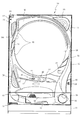
次いで、図4から図6を参照して、接続装置200の概略構成について説明する。図4は、接続装置200の正面図であり、図5は、接続装置200の上面図である。また、図6は、接続装置200の側面図である。なお、図6では、図面を簡素化して、理解を容易とするために、付勢部材250が二点鎖線を用いて模式的に図示されている。   Next, a schematic configuration of the connection device 200 will be described with reference to FIGS. 4 to 6. FIG. 4 is a front view of the connection device 200, and FIG. 5 is a top view of the connection device 200. FIG. 6 is a side view of the connection device 200. In FIG. 6, in order to simplify the drawing and facilitate understanding, the biasing member 250 is schematically illustrated using a two-dot chain line.

図4から図6に示すように、接続装置200は、透光性の樹脂材料から構成されるケース部材210と、そのケース部材210の内部に配設され導電性材料から構成される複数の端子部材220と、それら各端子部材220に対して近接離間可能な状態でケース部材210に配設され樹脂材料から構成される複数の第1レバー部材230及び第2レバー部材240と、それら各第1レバー部材230及び第2レバー部材240を端子部材220に近接する側へ向けて付勢する複数の付勢部材250とを備えている。   As shown in FIG. 4 to FIG. 6, the connection device 200 includes a case member 210 made of a translucent resin material, and a plurality of terminals arranged inside the case member 210 and made of a conductive material. The member 220, a plurality of first lever members 230 and second lever members 240 that are disposed on the case member 210 and are made of a resin material in a state in which the member 220 can approach and separate from each of the terminal members 220, and each of the first lever members 230 and 240. A plurality of biasing members 250 that bias the lever member 230 and the second lever member 240 toward the side close to the terminal member 220 are provided.

ケース部材210は、上面視(図5紙面垂直方向視)長方形の板状体に形成される上面壁211と、その上面壁211に対向配置されると共に底面視(図5紙面垂直方向視)長方形の板状体に形成される底面壁212と、それら上面壁211及び底面壁212の長手方向(図4紙面垂直方向、図5及び図6左右方向)両端を連結すると共に正面視(図4紙面垂直方向視)が頂部を直線状に除去した半円形状の板状体に形成される一対の端側壁213と、それら一対の端側壁213間を接続する一対の側面壁214とを主に備え、これら各部材211〜214により、中空の箱状に形成されている。   The case member 210 has an upper surface wall 211 formed in a rectangular plate-like body in a top view (viewed in the vertical direction in FIG. 5), and is disposed to face the upper wall 211 and is rectangular in a bottom view (viewed in the vertical direction in FIG. 5). The bottom wall 212 formed in the plate-like body, and the longitudinal direction (the vertical direction of FIG. 4 paper, the horizontal direction of FIG. 5 and FIG. 6) both ends of the top wall 211 and the bottom wall 212 are connected and viewed from the front (FIG. 4 paper surface). (Viewed in the vertical direction) mainly includes a pair of end side walls 213 formed in a semicircular plate-like body with the tops removed linearly, and a pair of side walls 214 connecting the pair of end side walls 213. These members 211 to 214 are formed in a hollow box shape.

上面壁211には、図5に示すように、配線W(図13参照)を挿抜するための開口である挿入孔211aが複数(本実施の形態では10個)穿設されており、ケース部材210の内部空間と外部とが挿入孔211aを介して連通されている。これら複数の挿入孔211aは、上面壁211の幅方向(図5上下方向)に所定間隔を隔てて配設される一対一組が、上面壁211の長手方向(図5左右方向)に沿って等間隔に複数組(本実施の形態では10組)が配設されている。   As shown in FIG. 5, the upper surface wall 211 has a plurality of insertion holes 211a (10 in this embodiment) that are openings for inserting and removing the wiring W (see FIG. 13). The internal space 210 and the outside communicate with each other through the insertion hole 211a. The plurality of insertion holes 211a are arranged along the longitudinal direction (left and right direction in FIG. 5) of the upper surface wall 211 in a pair that is disposed at a predetermined interval in the width direction (up and down direction in FIG. 5) of the upper surface wall 211. A plurality of sets (10 sets in the present embodiment) are arranged at equal intervals.

底面壁212には、その底面壁212の幅方向(図4左右方向)中央に位置しつつ長手方向(図6左右方向)に延設される正面視矩形状の底壁開口212aが開口形成されており、ケース部材210の内部空間と外部とが底壁開口212aを介して連通されている。これにより、ケース部材210の内部に配設される端子部材220の一端が外部へ突出され、基板(図示せず)に接続可能とされている。   The bottom wall 212 is formed with a bottom wall opening 212a having a rectangular shape in front view and extending in the longitudinal direction (left and right direction in FIG. 6) while being located in the center of the width direction (left and right direction in FIG. 4) of the bottom wall 212. The interior space of the case member 210 communicates with the outside via the bottom wall opening 212a. Accordingly, one end of the terminal member 220 disposed inside the case member 210 protrudes to the outside and can be connected to a substrate (not shown).

端側壁213は、一対が対向配置されており、これにより、ケース部材210の長手方向(図5及び図6左右方向)両端が閉塞されている。側面壁214は、ケース部材210の幅方向(図4左右方向)両側に配設されると共に、図6に示すように、底面壁212から立設されており、その側面壁214の立設端側(図6上側)には、上面壁211と一対の端側壁213と側面壁214とで囲まれる側壁開口214aが開口形成されている。   A pair of end side walls 213 are arranged opposite to each other, and thereby both ends of the case member 210 in the longitudinal direction (left and right direction in FIGS. 5 and 6) are closed. The side wall 214 is disposed on both sides of the case member 210 in the width direction (left and right direction in FIG. 4), and is erected from the bottom wall 212 as shown in FIG. On the side (upper side in FIG. 6), a side wall opening 214 a surrounded by the upper surface wall 211, the pair of end side walls 213, and the side wall 214 is formed.

これにより、ケース部材210の内部空間と外部とが側壁開口214aを介して連通され、第1レバー部材230及び第2レバー部材240の一端(第1操作部232及び第2操作部242)がケース部材210内から外部へ突出されると共に、これら第1レバー部材230及び第2レバー部材240が上下方向(図4上下方向)に移動可能に構成されている。   As a result, the internal space and the outside of the case member 210 are communicated with each other via the side wall opening 214a, and one end (the first operation portion 232 and the second operation portion 242) of the first lever member 230 and the second lever member 240 is connected to the case. The first lever member 230 and the second lever member 240 are configured to be movable in the vertical direction (the vertical direction in FIG. 4) while projecting from the member 210 to the outside.

ここで、ケース部材210には、区画壁215が形成されている。区画壁215は、ケース部材210の内部空間を複数の空間に区画するための部位であり、端側壁213と正面視形状(図4参照)が同形状の板状体として形成されている。この区画壁215は、上面壁211、底面壁212及び側面壁214を連結すると共に、複数(本実施の形態では9個)が、一対の端側壁213の対向間において、互いに平行かつ等間隔に配設されている。これにより、ケース部材210の内部空間は、その長手方向(図5及び図6左右方向)に沿って、10個の内部空間に区画される。   Here, a partition wall 215 is formed in the case member 210. The partition wall 215 is a part for partitioning the internal space of the case member 210 into a plurality of spaces, and is formed as a plate-like body having the same shape as the end side wall 213 and the front view (see FIG. 4). The partition wall 215 connects the top wall 211, the bottom wall 212, and the side wall 214, and a plurality (9 in this embodiment) are parallel to each other and equidistant from each other between the pair of end side walls 213. It is arranged. Thereby, the internal space of case member 210 is divided into ten internal spaces along the longitudinal direction (FIG. 5 and FIG. 6 left-right direction).

このように、ケース部材210に複数の区画壁215を形成することで、中空箱状に形成されたケース部材210全体としての剛性を高めることができる。また、各区画壁215の対向間に第1レバー部材230及び第2レバー部材240がそれぞれ配設されるので、これら両レバー部材230,240の移動を区画壁215で案内することができ、その結果、両レバー部材230,240の操作性の向上を図ることができる。更に、各区画壁215は、一対一組の挿入孔211aの各組同士の間(図5左右方向の間)を区画する位置に形成されているので、隣り合う組の内の一方の組の挿通行211aに配線Wを挿通する場合に、その配線Wが他方の組の挿入孔211aに既に挿通されている配線Wと接触することを回避することができる。   Thus, by forming the plurality of partition walls 215 in the case member 210, the rigidity of the entire case member 210 formed in a hollow box shape can be increased. In addition, since the first lever member 230 and the second lever member 240 are respectively disposed between the partition walls 215, the movement of the lever members 230 and 240 can be guided by the partition wall 215. As a result, the operability of both lever members 230 and 240 can be improved. Furthermore, each partition wall 215 is formed at a position that partitions each pair of insertion holes 211a (one in the left-right direction in FIG. 5), so that one of the adjacent pairs When the wiring W is inserted into the insertion row 211a, it is possible to avoid that the wiring W comes into contact with the wiring W that has already been inserted into the other set of insertion holes 211a.

第1レバー部材230及び第2レバー部材240は、挿入孔211aに対して配線Wを挿抜する際に操作される部材であり、一端側がケース部材210に揺動可能な状態で軸支されると共に(図7及び図8参照)、他端側(第1操作部232及び第2操作部242)がケース部材210の側壁開口214aから突出され、これら各操作部232,242が押圧操作されて押し下げられることで、挿入孔211aを介して配線Wを挿抜することが可能となる。   The first lever member 230 and the second lever member 240 are members that are operated when the wiring W is inserted into and removed from the insertion hole 211a. The first lever member 230 and the second lever member 240 are pivotally supported by the case member 210 in a swingable state. (See FIGS. 7 and 8), the other end side (the first operation portion 232 and the second operation portion 242) protrudes from the side wall opening 214a of the case member 210, and the operation portions 232 and 242 are pressed and pushed down. As a result, the wiring W can be inserted / removed through the insertion hole 211a.

付勢部材250は、第1レバー部材230及び第2レバー部材240を端子部材220に近接する側へ付勢するための弾性部材であり(図7及び図8参照)、図6に示すように、第1レバー部材230及び第2レバー部材240のそれぞれに1つずつが配設されている。よって、第1レバー部材230及び第2レバー部材240のそれぞれを独立して付勢可能(即ち、各挿入孔211aに配線Wを挿抜可能かつ配線Wを保持可能)に構成されている。   The urging member 250 is an elastic member for urging the first lever member 230 and the second lever member 240 toward the side close to the terminal member 220 (see FIGS. 7 and 8), as shown in FIG. One is provided for each of the first lever member 230 and the second lever member 240. Therefore, each of the first lever member 230 and the second lever member 240 can be independently biased (that is, the wiring W can be inserted into and removed from each insertion hole 211a and the wiring W can be held).

ここで、本実施の形態では、図5及び図6に示すように、第1レバー部材230と第2レバー部材240とがケース部材210の長手方向(図5及び図6左右方向)に沿って交互に配置されている。この場合、第2レバー部材240の第2操作部242は、第1レバー部材230の第1操作部232よりも、押圧操作方向(上面壁211から底面壁121へ向かう方向)と反対側(図4上側)へ後退して位置されている。   Here, in this embodiment, as shown in FIGS. 5 and 6, the first lever member 230 and the second lever member 240 are along the longitudinal direction of the case member 210 (the left-right direction in FIGS. 5 and 6). Alternatingly arranged. In this case, the second operation portion 242 of the second lever member 240 is opposite to the pressing operation direction (the direction from the top wall 211 toward the bottom wall 121) than the first operation portion 232 of the first lever member 230 (see FIG. 4 upper side).

即ち、第1操作部232が押圧方向奥側(図4下側)に、第2操作部242が押圧方向手前側(図4上側)に、互いに位置を異ならせて配置されているので、これら第1操作部232及び第2操作部242の両方を誤って一度に押圧操作するという誤操作を抑制することができる。よって、第1操作部232又は第2操作部242の内の一方のみの押圧操作を単独で行い易くすることができるので、第1操作部232及び第2操作部242の隣接間隔(図5及び図6左右方向間隔)や、第1操作部232及び第2操作部242の寸法を小さくすることができ、その結果、接続装置200全体としての小型化を図ることができる。   That is, since the first operation unit 232 is arranged at a position different from each other on the back side in the pressing direction (lower side in FIG. 4) and the second operation unit 242 is arranged on the front side in the pressing direction (upper side in FIG. 4), An erroneous operation in which both the first operation unit 232 and the second operation unit 242 are erroneously pressed at once can be suppressed. Accordingly, it is possible to easily perform the pressing operation of only one of the first operation unit 232 and the second operation unit 242, so that the adjacent interval between the first operation unit 232 and the second operation unit 242 (see FIG. 5 and FIG. 5). 6) and the dimensions of the first operation unit 232 and the second operation unit 242 can be reduced, and as a result, the connection device 200 as a whole can be reduced in size.

次いで、図7及び図8を参照して、接続装置200の詳細構成について説明する。図7は、図5のVII−VII線における接続装置200の断面図であり、図8は、図5のVIII−VIII線における接続装置200の断面図である。   Next, the detailed configuration of the connection device 200 will be described with reference to FIGS. 7 and 8. 7 is a cross-sectional view of the connection device 200 taken along line VII-VII in FIG. 5, and FIG. 8 is a cross-sectional view of the connection device 200 taken along line VIII-VIII in FIG.

図7及び図8に示すように、ケース部材210には、縦壁216が形成されている。縦壁216は、ケース部材210の内部空間を、その幅方向(図7及び図8左右方向)の一方側と他方側との2つの空間に区画するための部位であり、上面壁211の底面側から底面壁212へ向けて垂下される板状体として形成されている。この縦壁216は、一対一組の挿入孔211aの間から、図7及び図8に示す断面視において、底面壁212と重なる位置まで、垂直に垂下されると共に、長手方向一端側および他端側(図7及び図8紙面垂直方向奥側および手前側)が一対の端側壁213にそれぞれ連結されている。これにより、ケース部材210は、複数の区画壁215により長手方向(図7及び図8紙面垂直方向)に沿って10個に区画された内部空間が、更に、縦壁216によって幅方向(図7及び図8左右方向)に区画されることで、合計20個の内部空間に区画されている。即ち、複数の挿通行211aの一つずつに内部空間が形成されている。   As shown in FIGS. 7 and 8, a vertical wall 216 is formed in the case member 210. The vertical wall 216 is a part for partitioning the internal space of the case member 210 into two spaces on one side and the other side in the width direction (FIG. 7 and FIG. 8 in the left-right direction). It is formed as a plate-like body that hangs down from the side toward the bottom wall 212. The vertical walls 216 are vertically suspended from between a pair of insertion holes 211a to a position overlapping the bottom wall 212 in the cross-sectional views shown in FIGS. 7 and 8, and one end side and the other end in the longitudinal direction. The sides (the rear side and the front side in the direction perpendicular to the plane of FIG. 7 and FIG. 8) are respectively connected to the pair of end side walls 213. As a result, the case member 210 is further divided into ten internal spaces along the longitudinal direction (perpendicular to the plane of FIG. 7 and FIG. 8) by the plurality of partition walls 215, and the width direction (FIG. And in the left-right direction in FIG. 8), a total of 20 internal spaces are defined. That is, an internal space is formed in each of the plurality of insertion rows 211a.

このように、ケース部材210に、上述した複数の区画壁215に加え、縦壁216を形成することで、中空箱状に形成されたケース部材210全体としての剛性を更に高めることができる。また、縦壁216により端子部材220を支持することができるので、第1レバー部材230及び第2レバー部材240を端子部材220に強固に圧接させることができるので、配線Wの保持強度を高めることができる。更に、縦壁216は、一対一組の挿入孔211aの間(図7及び図8左右方向の間)を区画する位置に形成されているので、これら一対の挿入孔211aの内の一方の挿入孔211aに配線Wを挿通する場合に、その配線Wが他方の挿入孔211aに既に挿通されている配線Wと接触することを回避することができる。   Thus, by forming the vertical wall 216 in addition to the plurality of partition walls 215 described above in the case member 210, the rigidity of the entire case member 210 formed in a hollow box shape can be further increased. Further, since the terminal member 220 can be supported by the vertical wall 216, the first lever member 230 and the second lever member 240 can be firmly pressed against the terminal member 220, so that the holding strength of the wiring W is increased. Can do. Further, since the vertical wall 216 is formed at a position that divides the pair of insertion holes 211a (between the left and right directions in FIGS. 7 and 8), one of the pair of insertion holes 211a is inserted. When the wiring W is inserted into the hole 211a, it can be avoided that the wiring W comes into contact with the wiring W that has already been inserted into the other insertion hole 211a.

なお、縦壁216の両側面(図7及び図8の右側面および左側面)には、所定幅の凹溝216aがそれぞれ凹設されている。この凹溝216aは、一側(図7及び図8上側)が上面壁211を貫通すると共に、他側(図7及び図8下側)が縦壁216の中途まで延設されている。これにより、凹溝216aの他側(延設方向下端)には、段差部216bが形成されている。   In addition, a concave groove 216a having a predetermined width is formed in both side surfaces of the vertical wall 216 (the right side surface and the left side surface in FIGS. 7 and 8). One side (upper side in FIGS. 7 and 8) of the concave groove 216 a penetrates the upper surface wall 211, and the other side (lower side in FIGS. 7 and 8) extends to the middle of the vertical wall 216. Accordingly, a step 216b is formed on the other side (lower end in the extending direction) of the groove 216a.

また、上面壁211には、確認窓211bが開口形成されており、この確認窓211bを介して、凹溝216aの一側(延設方向上端、図7及び図8上側)と挿入孔211aとが連通されている。これにより、接続装置200をパチンコ機10に装着した後においても(図3参照)、端子部材220の組み込み忘れや組み込み不良、或いは、端子部材220自体の形状不良などを、確認窓211b及び凹溝216aを介して直接視認して、確認することができる。   In addition, a confirmation window 211b is formed in the upper surface wall 211. Through this confirmation window 211b, one side of the groove 216a (upper end in the extending direction, upper side in FIGS. 7 and 8) and the insertion hole 211a Is communicated. As a result, even after the connection device 200 is mounted on the pachinko machine 10 (see FIG. 3), the confirmation window 211b and the concave groove are not detected when the terminal member 220 is forgotten to be assembled or defective, or the terminal member 220 itself has a defective shape. It can be confirmed by directly viewing via 216a.

縦壁216の両側面には、端子部材220が背中合わせの状態で配設されている。端子部材220は、挿入孔211aから挿入された配線Wが電気的に接続される金属端子であり、金属材料からなる1枚の板状体をプレス加工により打ち抜き及び折曲して形成されている。ここで、端子部材220について、図9を参照して説明する。図9(a)は、端子部材220の側面図であり、図9(b)は、図9(a)の矢印IXb方向から視た端子部材220の正面図である。   On both side surfaces of the vertical wall 216, terminal members 220 are disposed back to back. The terminal member 220 is a metal terminal to which the wiring W inserted from the insertion hole 211a is electrically connected, and is formed by punching and bending a single plate made of a metal material by pressing. . Here, the terminal member 220 will be described with reference to FIG. FIG. 9A is a side view of the terminal member 220, and FIG. 9B is a front view of the terminal member 220 viewed from the direction of the arrow IXb in FIG. 9A.

図9に示すように、端子部材220は、中央に開口が形成された正面視ロ字状の本体部221と、その本体部221の開口内縁から延設され背面側(図9(a)左側、図9(b)紙面奥側)へ傾斜する傾斜片222と、本体部221の上縁から延設されると共にその延設先端が折り曲げられて正面側へ突出される突出片223と、本体部221の下縁から正面側へ向けて延設されると共にその延設先端が下方へ向けて折り曲げられる接続端224と、その接続端224を挟んで位置し本体部221の下縁から本体部221側へ折り返されつつ延設される一対の折り返し片225とを主に備えている。   As shown in FIG. 9, the terminal member 220 includes a main body portion 221 having a square shape in front view with an opening formed in the center, and a rear side (left side in FIG. 9A) extending from the inner edge of the opening of the main body portion 221. 9B, an inclined piece 222 inclined to the back side of the paper), a projecting piece 223 that extends from the upper edge of the main body 221 and is bent toward the front side with its extended tip bent, A connecting end 224 that extends from the lower edge of the portion 221 toward the front side, and that the extending tip is bent downward, and is located across the connecting end 224 and from the lower edge of the main body portion 221 to the main body portion It mainly includes a pair of folded pieces 225 that are folded while being folded toward the 221 side.

本体部221は、端子部材220の骨格をなす部位であり、その本体部221の幅寸法(図9(b)左右方向寸法)は、縦壁216の凹溝216aの幅寸法(図7及び図8紙面垂直方向寸法)よりも大きくされ、かつ、隣り合う区画壁215の対向間隔(例えば、図5及び図6左右方向寸法)よりも小さくされている。よって、本体部221は、縦壁216の側面であって、凹溝216aの非形成領域にその背面側が支持される(図7及び図8参照)。   The main body portion 221 is a part forming the skeleton of the terminal member 220, and the width dimension of the main body portion 221 (FIG. 9B) is the width dimension of the concave groove 216a of the vertical wall 216 (FIGS. 7 and 7). 8 (the vertical dimension in the drawing), and smaller than the facing interval between adjacent partition walls 215 (for example, the horizontal dimension in FIGS. 5 and 6). Therefore, the main body part 221 is a side surface of the vertical wall 216, and the back side thereof is supported by a non-formation region of the concave groove 216a (see FIGS. 7 and 8).

傾斜片222は、その幅寸法(図9(b)左右方向寸法)が縦壁216の凹溝の幅寸法よりも細幅に形成されている。よって、傾斜片222は、本体部221が縦壁216の側面に支持された状態では、縦壁216の凹溝216a内に収納される(図7及び図8参照)。よって、傾斜片222の先端(図9(a)下側端)が縦壁216の段差部216bに係止されることで、端子部材220がケース部材210の内部空間内に保持される。   The inclined piece 222 is formed so that its width dimension (dimension in the left-right direction in FIG. 9B) is narrower than the width dimension of the concave groove of the vertical wall 216. Therefore, the inclined piece 222 is accommodated in the concave groove 216a of the vertical wall 216 in a state where the main body portion 221 is supported on the side surface of the vertical wall 216 (see FIGS. 7 and 8). Therefore, the terminal member 220 is held in the internal space of the case member 210 by the tip of the inclined piece 222 (the lower end in FIG. 9A) being locked to the stepped portion 216b of the vertical wall 216.

突出片223は、配線Wとの主な接続(当接)箇所となる部位であり、第1レバー部材230及び第2レバー部材240の圧接面231a,241aにより押圧された配線Wが圧接される(図14参照)。接続片224は、外部端子基板199(図15参照)に電気的に接続される部位であり、底面壁212の底壁開口212aから外部に突出されている。なお、接続片224は、その折り曲げ部が、底面壁212の裏面側に凹設された凹設部内に収納されている。これにより、接続片224を外部端子基板199に接続する場合には、接続片224の折り曲げ部の上面側(図7及び図8上側)が、底面壁212の凹設部の底面側に支持されるので、その接続作業を効率的に行うことができる。   The protruding piece 223 is a portion that is a main connection (contact) portion with the wiring W, and the wiring W pressed by the pressure contact surfaces 231a and 241a of the first lever member 230 and the second lever member 240 is pressed. (See FIG. 14). The connection piece 224 is a part that is electrically connected to the external terminal board 199 (see FIG. 15), and protrudes to the outside from the bottom wall opening 212 a of the bottom wall 212. Note that the bent portion of the connection piece 224 is housed in a recessed portion that is recessed on the back surface side of the bottom wall 212. Thereby, when connecting the connection piece 224 to the external terminal board 199, the upper surface side (upper side in FIGS. 7 and 8) of the bent portion of the connection piece 224 is supported on the bottom surface side of the recessed portion of the bottom wall 212. Therefore, the connection work can be performed efficiently.

図7及び図8に戻って説明する。端子部材220に対向する位置には、その端子部材220に対して近接離間可能な状態で、第1レバー部材230及び第2レバー部材240がケース部材210に軸支されている。ここで、第1レバー部材230について、図10を参照して説明する。図10(a)は、第1レバー部材230の正面図であり、図10(b)は、図10(a)の矢印Xb方向から視た第1レバー部材230の側面図である。   Returning to FIG. 7 and FIG. The first lever member 230 and the second lever member 240 are pivotally supported by the case member 210 at a position facing the terminal member 220 so as to be close to and away from the terminal member 220. Here, the first lever member 230 will be described with reference to FIG. FIG. 10A is a front view of the first lever member 230, and FIG. 10B is a side view of the first lever member 230 viewed from the direction of the arrow Xb in FIG. 10A.

図10に示すように、第1レバー部材230は、第1基部231と、その第1基部231の一側に連設される第1操作部232とを備える。第1基部231は、第1操作部232と反対側の端部に連設される円柱状の軸支部233と、第1操作部232側の底面から突出される突出ピン234とを主に備えている。   As shown in FIG. 10, the first lever member 230 includes a first base portion 231 and a first operation portion 232 that is connected to one side of the first base portion 231. The first base portion 231 mainly includes a columnar shaft support portion 233 continuously provided at an end opposite to the first operation portion 232 and a protruding pin 234 protruding from the bottom surface on the first operation portion 232 side. ing.

第1基部231は、幅寸法(図10(a)左右方向寸法)が小さい小幅部と、その部位よりも幅寸法が大きな大幅部とからなり、小幅部の端部に軸支部233が配設されると共に、大幅部の底面に突出ピン234が配設されている。また、小幅部の上面側(図10上側)には、第1操作部232から離間する方向へ向けて下降傾斜する平坦面状の傾斜面231aが形成される一方、大幅部の正面側(図10(b)左側)には、第1操作部232と反対側を臨む平坦面状の係止面231bが形成されている。   The first base portion 231 includes a small width portion having a small width dimension (dimension in the left-right direction in FIG. 10A) and a large portion having a width dimension larger than that portion. In addition, a protruding pin 234 is disposed on the bottom surface of the large portion. Further, on the upper surface side (upper side in FIG. 10) of the small width portion, a flat surface-like inclined surface 231a that is inclined downward toward the direction away from the first operation portion 232 is formed, while the front side (see FIG. 10 (b) on the left side is formed with a flat locking surface 231b facing the side opposite to the first operating portion 232.

軸支部233は、ケース部材210に回動可能に軸支される部位である。ここで、ケース部材210による第1レバー部材230の軸支構造について、図12を参照して説明する。図12(a)は、ケース部材210の断面図であり、図12(b)は、図12(a)のXIIb−XIIb線におけるケース部材210の断面図である。なお、図12(a)は、図5におけるVII−VII線またはVIII−VIII線におけるケース部材210の断面図に対応する。   The shaft support portion 233 is a portion that is rotatably supported by the case member 210. Here, the shaft support structure of the first lever member 230 by the case member 210 will be described with reference to FIG. 12A is a cross-sectional view of the case member 210, and FIG. 12B is a cross-sectional view of the case member 210 taken along line XIIb-XIIb in FIG. 12A. 12A corresponds to a cross-sectional view of the case member 210 taken along the line VII-VII or the line VIII-VIII in FIG.

図12に示すように、ケース部材210の各区画壁215は、隣設する区画壁215との対向面から突設される突設段部215aをそれぞれ備えると共に、これら各突設段部215aの下側面(図12下側)には、円弧状に湾曲した湾曲面215a1が形成されている。よって、第1レバー部材230は、その軸支部233が湾曲面215a1により案内されることで、軸支部233を回動中心として、端子部材220に対して近接または離間する方向へ回動される(図7及び図8参照)。   As shown in FIG. 12, each partition wall 215 of the case member 210 includes a protruding step portion 215a protruding from a surface facing the adjacent partition wall 215, and each of the protruding step portions 215a A curved surface 215a1 curved in an arc shape is formed on the lower side surface (lower side in FIG. 12). Therefore, the first lever member 230 is rotated in the direction of approaching or separating from the terminal member 220 with the shaft support portion 233 as the rotation center, with the shaft support portion 233 being guided by the curved surface 215a1. (See FIGS. 7 and 8).

なお、ケース部材210の一対の端側壁213及びその端側壁213に隣設する区画壁215についても、それらの対向面には同様に湾曲面215a1を備える突接段部215aがそれぞれ突設されている。ここで、これら各端側壁213及び区画壁215に形成される突設段部215aの湾曲面215a1は、ケース部材210の正面視(即ち、図12の状態)において、各湾曲面215a1が同軸状に配置されている。   The pair of end side walls 213 of the case member 210 and the partition wall 215 adjacent to the end side wall 213 are also provided with protruding step portions 215a each having a curved surface 215a1 on the opposite surfaces. Yes. Here, the curved surfaces 215a1 of the protruding step portions 215a formed on the end side walls 213 and the partition walls 215 are coaxial with the curved surfaces 215a1 when the case member 210 is viewed from the front (that is, in the state of FIG. 12). Is arranged.

よって、これら各湾曲面215a1がそれぞれ異なる位置に配置される場合と比較して、ケース部材210の構造を簡素化することができ、その分、製造コストの削減を図ることができる。また、ケース部材210を樹脂材料から構成する場合には、樹脂成型性の向上を図ることができる。更に、後述するように、第1レバー部材230と第2レバー部材240とは第1基部231と第2基部241とが同じ形状に構成されているので、これら第1レバー部材230及び第2レバー部材240のケース部材210への組み込み作業を共通化して、作業性の向上を図ることができる。また、第1レバー部材230と第2レバー部材240とのケース部材210への組み込み位置を任意に選択することができる。   Therefore, compared with the case where these curved surfaces 215a1 are arranged at different positions, the structure of the case member 210 can be simplified, and the manufacturing cost can be reduced accordingly. Further, when the case member 210 is made of a resin material, the resin moldability can be improved. Further, as will be described later, since the first base member 231 and the second base member 241 have the same shape in the first lever member 230 and the second lever member 240, the first lever member 230 and the second lever member 241 are formed. The work of assembling the member 240 into the case member 210 can be shared to improve workability. Further, the positions where the first lever member 230 and the second lever member 240 are incorporated into the case member 210 can be arbitrarily selected.

図10に戻って説明する。突出ピン234は、付勢部材250が外嵌される部位であり、先細円柱状に形成されている。傾斜面231aは、端子部材220へ向けて下降傾斜されているので、配線Wを挿入孔211aから抜き取った状態で第1レバー部材230を端子部材220へ近接する方向へ回動させる場合には、その傾斜面231aの傾斜により端子部材220の突出片223先端を案内することができる。よって、突出片233先端が第1基部231に引っ掛かることを抑制し、端子部材220を上方へ持ち上げつつ縦壁216の側面へ押圧することができるので、第1レバー部材230を初期位置まで確実に復帰させることができる(図7及び図8参照)。   Returning to FIG. The protruding pin 234 is a part to which the urging member 250 is externally fitted, and is formed in a tapered cylindrical shape. Since the inclined surface 231a is inclined downward toward the terminal member 220, when the first lever member 230 is rotated in the direction approaching the terminal member 220 in a state where the wiring W is removed from the insertion hole 211a, The tip of the protruding piece 223 of the terminal member 220 can be guided by the inclination of the inclined surface 231a. Therefore, it is possible to suppress the tip of the protruding piece 233 from being caught by the first base portion 231, and to press the terminal member 220 to the side surface of the vertical wall 216 while lifting the terminal member 220 upward, so that the first lever member 230 can be reliably moved to the initial position. It can be restored (see FIGS. 7 and 8).

係止面231bは、ケース部材210の上面壁211における端縁(側壁開口214aの内縁)に当接する部位である。即ち、第1レバー部材230は、配線Wが挿入孔211aに挿入されていない状態において、付勢部材250の付勢力により端子部材250に近接される方向へ回動されると、係止面231bが上面壁211の端縁に当接されることで、その回動が規制される(図7及び図8参照)。なお、第1レバー部材230は、付勢部材250の付勢力に抗して、端子部材250から離間する方向へ回動されると、第1基部231の底面側が側面壁214の上端(側壁開口214aの内縁)に当接されることで、その回動が規制される。   The locking surface 231 b is a part that abuts on an end edge (inner edge of the side wall opening 214 a) of the upper surface wall 211 of the case member 210. That is, when the first lever member 230 is rotated in the direction approaching the terminal member 250 by the urging force of the urging member 250 in a state where the wiring W is not inserted into the insertion hole 211a, the locking surface 231b. Is abutted against the edge of the upper surface wall 211 to restrict its rotation (see FIGS. 7 and 8). When the first lever member 230 is rotated in a direction away from the terminal member 250 against the urging force of the urging member 250, the bottom surface side of the first base 231 is the upper end (side wall opening) of the side wall 214. The rotation is regulated by contacting the inner edge of 214a.

第1操作部232は、ケース部材210から突出される部位であり、第1基部231から大幅部と平行な方向へ向けて直線状に延設されている。この第1操作部232の上面側(図10(b)上側)には、第1操作面235が形成されている。第1操作面235は、第1レバー部材230の押圧操作時に、作業者により押圧される平坦面状であり、その平坦面には、小突起235a及び大突起235bが突設されると共に、窪み部235cが凹設されている。   The first operation portion 232 is a portion protruding from the case member 210 and extends linearly from the first base portion 231 in a direction parallel to the large portion. A first operation surface 235 is formed on the upper surface side (upper side in FIG. 10B) of the first operation unit 232. The first operation surface 235 is a flat surface that is pressed by an operator when the first lever member 230 is pressed, and a small protrusion 235a and a large protrusion 235b are provided on the flat surface, and the depression is depressed. The part 235c is recessed.

小突起235a及び大突起235bは、押圧操作時において、滑り止めの役割を果たす部位であり、第1操作部232の幅方向(図10(a)左右方向)に延びる断面三角形の突条状の突起として形成されている。なお、本実施の形態では、第1操作部232の第1操作面235には、第1基部231側に2本の小突起235aが列設されると共に、第1操作部232の先端側(図10(b)右側)に小突起235aと大突起235bとが1本ずつ列設されている。   The small protrusions 235a and the large protrusions 235b are portions that play a role of preventing slippage during the pressing operation, and have a ridge shape with a triangular cross section extending in the width direction (the left-right direction in FIG. 10A) of the first operation portion 232. It is formed as a protrusion. In the present embodiment, on the first operation surface 235 of the first operation unit 232, two small protrusions 235a are arranged on the first base 231 side, and the front end side of the first operation unit 232 ( A small protrusion 235a and a large protrusion 235b are arranged in a row on the right side of FIG.

なお、大突起235bは、第1操作部232(第1操作面235)の先端側(即ち、軸支部233から最も離間する側)に配設されると共に、大突起235bの第1操作面235からの突設高さは、小突起235aの第1操作面235からの突設高さよりも高くされている。また、大突起235bは、その先端位置が軸支部233の軸心(即ち、第1レバー部材230の回動中心)から距離L1だけ離間されている。   The large protrusion 235b is disposed on the distal end side of the first operation portion 232 (first operation surface 235) (that is, the side farthest from the shaft support portion 233), and the first operation surface 235 of the large protrusion 235b. The projecting height from the first projection surface 235a is higher than the projecting height from the first operation surface 235 of the small projection 235a. Further, the large protrusion 235b is spaced from the axial center of the shaft support portion 233 (that is, the rotation center of the first lever member 230) by a distance L1.

窪み部235cは、小突起235a及び大突起235bと同様に、押圧操作時における滑り止めの役割を果たす部位であり、第1操作部232の幅方向(図10(a)左右方向)中央において、正面視円形の凹部として第1操作面235に凹設されている。   Like the small protrusion 235a and the large protrusion 235b, the indentation part 235c is a part that plays a role of anti-slip at the time of pressing operation, and in the center of the width direction (FIG. 10 (a) left-right direction) of the first operation part 232, The first operation surface 235 is recessed as a circular recess in front view.

次いで、第2レバー部材240について、図11を参照して説明する。図11(a)は、第2レバー部材240の正面図であり、図11(b)は、図11(a)の矢印XIb方向から視た第2レバー部材240の側面図である。   Next, the second lever member 240 will be described with reference to FIG. Fig.11 (a) is a front view of the 2nd lever member 240, FIG.11 (b) is a side view of the 2nd lever member 240 seen from the arrow XIb direction of Fig.11 (a).

図11に示すように、第2レバー部材240は、第2基部241と、その第2基部241の一側に連設される第2操作部242とを備える。第2基部241は、第2操作部242と反対側の端部に連設される円柱状の軸支部243と、第2操作部242側の底面から突出される突出ピン244とを主に備えている。   As shown in FIG. 11, the second lever member 240 includes a second base portion 241 and a second operation portion 242 that is connected to one side of the second base portion 241. The second base portion 241 mainly includes a columnar shaft support portion 243 that is connected to an end opposite to the second operation portion 242 and a protruding pin 244 that protrudes from the bottom surface on the second operation portion 242 side. ing.

ここで、第2基部241は、第1レバー部材230の第1基部231と同様の形状に構成(即ち、傾斜面241a、係止面241b、軸支部243及び突出ピン244はそれぞれ第1基部231の傾斜面231a、係止面231b、軸支部233及び突出ピン234と同じ形状に構成)されており、ケース部材210により支持される支持構造も第1基部231の場合と同様であるので、その説明は省略する。   Here, the second base portion 241 is configured in the same shape as the first base portion 231 of the first lever member 230 (that is, the inclined surface 241a, the locking surface 241b, the shaft support portion 243, and the protruding pin 244 are each in the first base portion 231). The inclined surface 231a, the locking surface 231b, the shaft support portion 233 and the protruding pin 234 are configured in the same shape), and the support structure supported by the case member 210 is the same as that of the first base portion 231. Description is omitted.

なお、このように、第1レバー部材230の第1基部231と第2レバー部材240の第2基部241とを同じ形状とすることで、ケース部材210における第1レバー部材230の支持構造と第2レバー部材240の支持構造とを共通の形状とすることができる(図12参照)。よって、ケース部材210の構造を簡素化して、成型性の向上を図ることができる。また、第1レバー部材230及び第2レバー部材240のケース部材210への組み込み方法を共通として、組み立て性の向上を図ることができる。よって、接続装置200の製造コストを削減して、その分、パチンコ機10の製品コストの削減を図ることができる。   As described above, the first base member 231 of the first lever member 230 and the second base member 241 of the second lever member 240 have the same shape. The support structure of the two lever member 240 can be formed in a common shape (see FIG. 12). Therefore, the structure of the case member 210 can be simplified and the moldability can be improved. Further, the assemblability can be improved by using a common method for incorporating the first lever member 230 and the second lever member 240 into the case member 210. Therefore, the manufacturing cost of the connection device 200 can be reduced, and the product cost of the pachinko machine 10 can be reduced accordingly.

なお、第1基部231及び第2基部241とは、図7及び図8において、第1レバー部材230及び第2レバー部材240の重複領域に形成される部位であり、非重複領域に形成される部位は、第1操作部232及び第2操作部242である。よって、第1基部231と第2基部241とは、第1操作部232及び第2操作部242の連設位置が異なるという点で相違する。   7 and 8, the first base portion 231 and the second base portion 241 are portions formed in the overlapping region of the first lever member 230 and the second lever member 240, and are formed in the non-overlapping region. The parts are a first operation unit 232 and a second operation unit 242. Therefore, the first base portion 231 and the second base portion 241 are different in that the connection positions of the first operation portion 232 and the second operation portion 242 are different.

第2操作部242は、ケース部材210から突出される部位であり、第2基部231の大幅部から上方へ向けて延設される延設部とその延設部から上昇傾斜しつつ延設される傾斜部とから側面視略くの字状に形成されている。この第2操作部242の傾斜部の上面側(図11(b)上側)には、第2操作面245が形成されている。第2操作面245は、第2レバー部材240の押圧操作時に、作業者により押圧される平坦面状であり、その平坦面には、小突起245a及び大突起245bが突設されると共に、窪み部245cが凹設されている。   The second operation portion 242 is a portion protruding from the case member 210, and extends from the large portion of the second base portion 231 upward, and extends while being inclined upward from the extended portion. It is formed in a substantially U shape in side view from the inclined portion. A second operation surface 245 is formed on the upper surface side (upper side in FIG. 11B) of the inclined portion of the second operation portion 242. The second operation surface 245 has a flat surface shape that is pressed by the operator when the second lever member 240 is pressed, and a small protrusion 245a and a large protrusion 245b project from the flat surface, and the depression is depressed. The portion 245c is recessed.

小突起245a及び大突起245bは、押圧操作時において、滑り止めの役割を果たす部位であり、第2操作部242の幅方向(図11(a)左右方向)に延びる断面三角形の突条状の突起として形成されている。なお、本実施の形態では、第2操作部242の第2操作面245には、第2基部241側に3本の小突起245aが列設されると共に、第2操作部242の先端側(図11(b)右側)に小突起245aと大突起245bとが1本ずつ列設されている。   The small protrusions 245a and the large protrusions 245b are portions that play a role of slip prevention during a pressing operation, and have a triangular shape in the shape of a triangular section extending in the width direction (the left-right direction in FIG. 11A) of the second operation portion 242. It is formed as a protrusion. In the present embodiment, on the second operation surface 245 of the second operation unit 242, three small protrusions 245 a are arranged on the second base 241 side, and the tip side of the second operation unit 242 ( In FIG. 11 (b) right side), one small protrusion 245a and one large protrusion 245b are arranged in a row.

なお、大突起245bは、第2操作部242(第2操作面245)の先端側(即ち、軸支部243から最も離間する側)に配設されると共に、大突起245bの第2操作面245からの突設高さは、小突起245aの第2操作面245からの突設高さよりも高くされている。また、大突起245bは、その先端位置が軸支部243の軸心(即ち、第2レバー部材240の回動中心)から距離L2だけ離間されている。   The large protrusion 245b is disposed on the distal end side of the second operation portion 242 (second operation surface 245) (that is, the side farthest from the shaft support portion 243), and the second operation surface 245 of the large protrusion 245b. The projecting height from the second projection surface 245a is higher than the projecting height from the second operation surface 245 of the small projection 245a. Further, the large protrusion 245b is spaced from the axial center of the shaft support portion 243 (that is, the rotation center of the second lever member 240) by a distance L2.

窪み部245cは、小突起245a及び大突起245bと同様に、押圧操作時における滑り止めの役割を果たす部位であり、第2操作部242の幅方向(図11(a)左右方向)中央において、正面視円形の凹部として第2操作面245に凹設されている。   Like the small protrusion 245a and the large protrusion 245b, the hollow portion 245c is a part that plays a role of preventing slippage at the time of the pressing operation, and in the center of the width direction (FIG. 11 (a) left-right direction) of the second operation portion 242. The second operation surface 245 is recessed as a circular recess in front view.

ここで、第2レバー部材240は、軸支部243の軸心から大突起245bまでの距離L2が、第1レバー部材230における軸支部233から大突起235bまでの距離L1よりも長くされている(L1<L2)。これにより、第2レバー部材240の大突起245bの先端位置における移動軌跡が、第1レバー部材230の第1操作部232の突出先端よりも外方を通過する構造(図14参照)を、第2レバー部材240の第2操作部242の押圧操作に要する操作力を小さくしつつ、構成することができる。   Here, in the second lever member 240, the distance L2 from the shaft center of the shaft support portion 243 to the large protrusion 245b is longer than the distance L1 from the shaft support portion 233 to the large protrusion 235b in the first lever member 230 ( L1 <L2). As a result, a structure (see FIG. 14) in which the movement trajectory at the tip position of the large protrusion 245 b of the second lever member 240 passes outward from the protruding tip of the first operating portion 232 of the first lever member 230 (see FIG. 14). The two-lever member 240 can be configured while reducing the operating force required for the pressing operation of the second operating portion 242.

即ち、上述した距離L2を距離L1より短くしても、第2レバー部材240の軸支部243の配設位置を、第1レバー部材230の軸支部233の配設位置よりも外方に位置させることで、上述した大突起245bの先端における移動軌跡が第1操作部232の突出先端よりも外方を通過する構造は構成できるが、この場合には、第2レバー部材240の第2操作部242の押圧操作に要する操作力が大きくなり、操作性が悪化する。   That is, even if the distance L2 described above is shorter than the distance L1, the disposition position of the shaft support portion 243 of the second lever member 240 is positioned outward from the disposition position of the shaft support portion 233 of the first lever member 230. Thus, a structure in which the movement trajectory at the tip of the large protrusion 245b described above passes outward from the protruding tip of the first operating portion 232 can be configured. In this case, the second operating portion of the second lever member 240 is configured. The operating force required for the pressing operation 242 increases, and the operability deteriorates.

これに対し、本実施の形態のように構成することで、第2レバー部材240の第2操作部242を押圧操作する際に、第1操作部232及び第2操作部242の両方を誤って一度に押圧操作するという誤操作を移動軌跡の関係によって抑制することができるだけでなく、第2操作部242の操作力を軽減して、その操作性の向上を図ることもできる。   On the other hand, by configuring as in the present embodiment, both the first operation unit 232 and the second operation unit 242 are erroneously operated when the second operation unit 242 of the second lever member 240 is pressed. Not only can the erroneous operation of pressing at a time be suppressed by the relationship of the movement trajectory, but also the operability of the second operation unit 242 can be reduced and the operability can be improved.

図7及び図8に戻って説明する。上述のように構成された第1レバー部材230及び第2レバー部材240は、ケース部材210に装着され、それぞれが端子部材220に最も近接する状態(即ち、係止面231b、241b(図10及び図11参照)が上面壁211の端縁(側壁開口214aの内縁)に当接された状態)において、第1操作部232の第1操作面235及び第2操作部242の第2操作面245がそれぞれ突出先端部(図7及び図8の左方または右方)へ向かうに従って上昇傾斜されているので、第1レバー部材230及び第2レバー部材240を押圧操作する際の操作性の向上を図ることができる。   Returning to FIG. 7 and FIG. The first lever member 230 and the second lever member 240 configured as described above are mounted on the case member 210 and are in the state closest to the terminal member 220 (that is, the locking surfaces 231b and 241b (see FIG. 10 and FIG. 10). 11) is in contact with the edge of the upper surface wall 211 (the inner edge of the side wall opening 214a)), the first operation surface 235 of the first operation unit 232 and the second operation surface 245 of the second operation unit 242. Are inclined upwardly toward the projecting tip (left or right in FIGS. 7 and 8), thereby improving the operability when pressing the first lever member 230 and the second lever member 240. Can be planned.

即ち、第1レバー部材230及び第2レバー部材240を押圧操作する(図7及び図8下方へ押し下げる)際には、第1レバー部材230及び第2レバー部材240の回動移動に伴って第1操作部232の第1操作面235上を又は第2操作部242の第2操作面245上を滑ろうとする操作者の指を、突出先端部へ向かうに従って上昇傾斜される第1操作面235又は第2操作面245により係止することができ、これにより、押圧操作の操作性の向上を図ることができる。   That is, when the first lever member 230 and the second lever member 240 are pressed (lowered downward in FIGS. 7 and 8), the first lever member 230 and the second lever member 240 are moved in accordance with the rotational movement. The first operation surface 235 that is inclined upward as the finger of the operator who tries to slide on the first operation surface 235 of the first operation unit 232 or the second operation surface 245 of the second operation unit 242 moves toward the protruding tip. Or it can latch by the 2nd operation surface 245, and, thereby, the operativity of pressing operation can be aimed at.

更に、第1操作部232の第1操作面235及び第2操作部242の第2操作面245に形成される複数の突起の内で、その突設高さが最も高くされる大突起235b,245bは、第1操作面235及び第2操作面245の突出先端側(即ち、軸支部233,243から最も離間する側)に配設されている。よって、第1レバー部材230及び第2レバー部材240を押圧操作する際には、第1操作部232の第1操作面235及び第2操作部242の第2操作面245のそれぞれに形成された複数の突起(小突起235a,245a及び大突起235b,245b)により操作者の指を密着させることができるだけでなく、第1レバー部材230及び第2レバー部材240の回動移動に伴って第1操作部232の第1操作面235上を又は第2操作部242の第2操作面245上を滑ろうとする操作者の指を、突出先端に突設される高い突起(大突起235b,245b)により係止することができる。これにより、押圧操作の操作性の向上を図ることができる。   Further, among the plurality of protrusions formed on the first operation surface 235 of the first operation portion 232 and the second operation surface 245 of the second operation portion 242, the large protrusions 235b and 245b having the highest protrusion height. Are disposed on the projecting tip side of the first operation surface 235 and the second operation surface 245 (that is, the side farthest from the shaft support portions 233 and 243). Accordingly, when the first lever member 230 and the second lever member 240 are pressed, the first operation surface 235 of the first operation unit 232 and the second operation surface 245 of the second operation unit 242 are formed. The plurality of protrusions (small protrusions 235a and 245a and large protrusions 235b and 245b) not only allow the operator's finger to be brought into close contact, but also the first lever member 230 and the second lever member 240 move in the first direction. High protrusions (large protrusions 235b and 245b) that project the operator's finger on the first operation surface 235 of the operation unit 232 or the second operation surface 245 of the second operation unit 242 at the protruding tip. Can be locked. Thereby, the operativity of pressing operation can be improved.

このように、指の滑りを防止できるので、第1操作部230及び第2操作部240の間の隣接間隔や、第1操作部232及び第2操作部242の寸法を小さくしても、各突起(小突起235a,245a及び大突起235b,245b)の作用により押圧操作の操作性を効果的に確保することができるので、その分、接続装置200の小型化を図ることができる。   As described above, since the finger can be prevented from slipping, even if the adjacent distance between the first operation unit 230 and the second operation unit 240 and the size of the first operation unit 232 and the second operation unit 242 are reduced, Since the operability of the pressing operation can be effectively ensured by the action of the protrusions (the small protrusions 235a and 245a and the large protrusions 235b and 245b), the connection device 200 can be downsized accordingly.

付勢部材250は、第1レバー部材230及び第2レバー部材240を端子部材220に近接する側へ向けて付勢するための部材であり、金属線材を巻回したコイルスプリングとして構成され、第1レバー部材230及び第2レバー部材240のそれぞれに1本が配設されている。   The biasing member 250 is a member for biasing the first lever member 230 and the second lever member 240 toward the side close to the terminal member 220, and is configured as a coil spring wound with a metal wire. One is provided for each of the one lever member 230 and the second lever member 240.

この付勢部材250は、弾性的に圧縮された圧縮状態で、一端側が第1レバー部材230又は第2レバー部材240の突出ピン234,244に外嵌されると共に、他端側がケース部材210の底面壁212から突出される突出ピン212bに外嵌されている。よって、第1レバー部材230及び第2レバー部材240は、付勢部材250の弾性回復力により、軸支部233,243を回動中心として、端子部材220に近接する側へ向けて付勢されている。   The biasing member 250 is in an elastically compressed state, and one end side is externally fitted to the projecting pins 234 and 244 of the first lever member 230 or the second lever member 240 and the other end side is the case member 210. It is fitted on a protruding pin 212b protruding from the bottom wall 212. Therefore, the first lever member 230 and the second lever member 240 are urged toward the side close to the terminal member 220 with the shaft support portions 233 and 243 as the rotation center by the elastic recovery force of the urging member 250. Yes.

ここで、図13を参照して、接続装置200に対する配線Wの接続および取り外し方法について説明する。図13は、接続装置200の断面図であり、図5のVIII−VIII線における断面図に対応する。なお、第1レバー部材230及び第2レバー部材240による配線Wの接続構造は共に同様であるので、ここでは、第2レバー部材240による配線Wの接続構造を一例として説明し、第1レバー部材230による配線Wの接続構造についての説明を省略する。   Here, with reference to FIG. 13, the connection and removal method of the wiring W with respect to the connection apparatus 200 is demonstrated. FIG. 13 is a cross-sectional view of the connection device 200 and corresponds to the cross-sectional view taken along the line VIII-VIII in FIG. In addition, since the connection structure of the wiring W by the 1st lever member 230 and the 2nd lever member 240 is the same, here, the connection structure of the wiring W by the 2nd lever member 240 is demonstrated as an example, and the 1st lever member is demonstrated. A description of the wiring W connection structure 230 is omitted.

図13に示すように、接続装置200に配線Wを接続する場合には、まず、第2レバー部材240の第2操作部242における第2操作面245を、付勢部材250の付勢力に抗しつつ、下方(図13下方)へ向けて押圧操作して、第2レバー部材240を押し下げる。これにより、第2レバー部材240が、軸支部243を回動中心として、端子部材220から離間する側へ向けて回動され、第2レバー部材240の第2基体241における傾斜面241aが後退される。よって、挿入孔211aが開放されるので、かかる挿入孔211aから配線Wを挿入して、端子部材220の突出片223と第2レバー部材240の第2基体241との間に配線Wを配置した後、第2レバー部材240の押圧操作を解除する。その結果、第2レバー部材240が、付勢部材250の弾性回復力により、端子部材220に近接する側へ向けて回動され、その第2レバー部材240の回動により、配線Wが端子部材220に圧接されることで、配線Wと端子部材220とが電気的に接続される。   As shown in FIG. 13, when connecting the wiring W to the connection device 200, first, the second operation surface 245 in the second operation portion 242 of the second lever member 240 is resisted against the urging force of the urging member 250. However, the second lever member 240 is pushed down by performing a pressing operation downward (downward in FIG. 13). As a result, the second lever member 240 is rotated toward the side away from the terminal member 220 with the shaft support portion 243 as the rotation center, and the inclined surface 241a of the second base 241 of the second lever member 240 is retracted. The Therefore, since the insertion hole 211a is opened, the wiring W is inserted from the insertion hole 211a, and the wiring W is disposed between the protruding piece 223 of the terminal member 220 and the second base 241 of the second lever member 240. Thereafter, the pressing operation of the second lever member 240 is released. As a result, the second lever member 240 is rotated toward the side close to the terminal member 220 by the elastic recovery force of the biasing member 250, and the wiring W is connected to the terminal member by the rotation of the second lever member 240. By being in pressure contact with 220, the wiring W and the terminal member 220 are electrically connected.

一方、接続装置200から配線Wを取り外す場合には、まず、図13に示す状態から、第2レバー部材240の第2操作部242における第2操作面245を、付勢部材250の付勢力に抗しつつ、下方(図13下方)へ向けて押圧操作して、第2レバー部材240を押し下げる。これにより、第2レバー部材240が、軸支部243を回動中心として、端子部材220から離間する側へ向けて回動され、端子部材220と第2レバー部材240との間に狭持されていた配線Wが開放されるので、配線Wを接続装置200から取り外すことができる。配線Wを取り外した後は、第2レバー部材240の押圧操作を解除することで、第2レバー部材240が、付勢部材250の弾性回復力により、端子部材220に近接する側へ向けて回動され、初期位置に復帰される(図8参照)。   On the other hand, when removing the wiring W from the connection device 200, first, from the state shown in FIG. 13, the second operating surface 245 in the second operating portion 242 of the second lever member 240 is used as the biasing force of the biasing member 250. The second lever member 240 is pushed down by pressing downward (downward in FIG. 13) while resisting. As a result, the second lever member 240 is rotated toward the side away from the terminal member 220 with the shaft support portion 243 as the rotation center, and is sandwiched between the terminal member 220 and the second lever member 240. Since the wiring W is released, the wiring W can be removed from the connection device 200. After the wiring W is removed, the pressing operation of the second lever member 240 is released, so that the second lever member 240 is rotated toward the side close to the terminal member 220 by the elastic recovery force of the biasing member 250. Moved to the initial position (see FIG. 8).

ここで、図13に示すように、配線Wが接続された状態(即ち、第2レバー部材240が配線Wを端子部材220に圧接した状態)では、第1操作部232の突出先端部が、第2操作部242の突出先端部よりも押圧方向視(図13上下方向視)で外方に位置している。   Here, as shown in FIG. 13, in a state where the wiring W is connected (that is, a state where the second lever member 240 presses the wiring W against the terminal member 220), the protruding tip of the first operation portion 232 is It is located outward from the projecting tip of the second operating portion 242 in the pressing direction (viewed in the vertical direction in FIG. 13).

具体的には、本実施の形態では、配線Wを接続するための空間を担保した状態(即ち、端子部材220の突出片223と第2レバー部材240の第2基体241との間に配線Wを配置するための空間を設けた状態)において、第1操作面235から突設される大突起235bの先端位置が、第2操作部242の突出先端よりも、ケース部材210の幅方向(図13左右方向)外方へ距離d2だけ突出して位置するように構成されている。これにより、例えば、配線Wを接続するため、或いは、配線Wを取り外すために、第1操作面235のみを押圧操作する場合には、第2操作部242よりも距離d2だけ外方に突出する領域を利用して、第1操作面235のみの押圧操作を、隣の第2操作部242に阻害されることなく、単独で行い易くすることができる。   Specifically, in the present embodiment, the space for connecting the wiring W is secured (that is, the wiring W between the protruding piece 223 of the terminal member 220 and the second base 241 of the second lever member 240). In the width direction of the case member 210 (see FIG. 5), the tip position of the large protrusion 235b protruding from the first operation surface 235 is more than the protruding tip of the second operation portion 242. (13 left-right direction) It is configured to project outward by a distance d2. Thereby, for example, when only the first operation surface 235 is pressed to connect the wiring W or to remove the wiring W, the projection protrudes outward by the distance d2 from the second operation unit 242. By using the region, it is possible to easily perform the pressing operation only on the first operation surface 235 without being obstructed by the adjacent second operation unit 242.

よって、配線Wの取り外し作業を行うために、第1操作部232の第1操作面235を押圧操作する場合に、第1操作部232及び第2操作部242の両方を誤って一度に押圧操作するという誤操作を抑制することができる。従って、その分、第1操作部232及び第2操作部242の間の隣接間隔(図13紙面垂直方向間隔)や、第1操作部232及び第2操作部242の寸法を小さくすることができ、接続装置200の小型化を図ることができる。   Therefore, when the first operation surface 235 of the first operation unit 232 is pressed in order to remove the wiring W, both the first operation unit 232 and the second operation unit 242 are erroneously pressed at once. It is possible to suppress an erroneous operation of performing. Accordingly, it is possible to reduce the adjacent interval between the first operation unit 232 and the second operation unit 242 (the interval in the vertical direction in FIG. 13) and the dimensions of the first operation unit 232 and the second operation unit 242. Therefore, the connection device 200 can be reduced in size.

図7及び図8に戻って説明する。上述のように構成された第1レバー部材230及び第2レバー部材240は、ケース部材210に装着され、それぞれが端子部材220に最も近接する状態(即ち、係止面231b、241b(図10及び図11参照)が上面壁211の端縁(側壁開口214aの内縁)に当接された状態)において、第1操作部232の突出先端部が、第2操作部242の突出先端部よりも押圧方向視(図7及び図8上下方向視)で外方に位置している。   Returning to FIG. 7 and FIG. The first lever member 230 and the second lever member 240 configured as described above are mounted on the case member 210 and are in the state closest to the terminal member 220 (that is, the locking surfaces 231b and 241b (see FIG. 10 and FIG. 10). 11) is in contact with the edge of the top wall 211 (the inner edge of the side wall opening 214a), the protruding tip of the first operating portion 232 is pressed more than the protruding tip of the second operating portion 242. It is located outward in a direction view (viewed in the vertical direction in FIGS. 7 and 8).

具体的には、本実施の形態では、配線Wを接続する前の状態において、第1操作面235から突設される大突起235bの先端位置が、第2操作部242の突出先端よりも、ケース部材210の幅方向(図7及び図8左右方向)外方へ距離d1だけ突出して位置するように構成されている(図5参照)。これにより、例えば、配線Wを挿入するために、第1操作面235のみを押圧操作する場合には、第2操作部242よりも距離d1だけ外方に突出する領域を利用して、第1操作面235のみの押圧操作を、隣の第2操作部242に阻害されることなく、単独で行い易くすることができる。   Specifically, in the present embodiment, in the state before connecting the wiring W, the tip position of the large projection 235b that protrudes from the first operation surface 235 is larger than the projection tip of the second operation unit 242. The case member 210 is configured to project outward by a distance d1 in the width direction (left and right direction in FIGS. 7 and 8) (see FIG. 5). Accordingly, for example, when only the first operation surface 235 is pressed in order to insert the wiring W, the first projection is performed using the region protruding outward from the second operation unit 242 by the distance d1. The pressing operation only on the operation surface 235 can be easily performed independently without being obstructed by the adjacent second operation unit 242.

よって、配線Wを挿入する作業を行うために、第1操作部232の第1操作面235を押圧操作する場合に、第1操作部232及び第2操作部242の両方を誤って一度に押圧操作するという誤操作を抑制することができる。従って、その分、第1操作部232及び第2操作部242の間の隣接間隔(図7及び図8紙面垂直方向間隔)や、第1操作部232及び第2操作部242の寸法を小さくすることができ、接続装置200の小型化を図ることができる。   Therefore, when the first operation surface 235 of the first operation unit 232 is pressed to perform the operation of inserting the wiring W, both the first operation unit 232 and the second operation unit 242 are erroneously pressed at once. The erroneous operation of operating can be suppressed. Accordingly, the adjacent interval between the first operation unit 232 and the second operation unit 242 (the vertical interval in FIG. 7 and FIG. 8) and the dimensions of the first operation unit 232 and the second operation unit 242 are reduced accordingly. The connection device 200 can be downsized.

また、第1レバー部材230及び第2レバー部材240は、ケース部材210の一側(例えば、図7及び図8右側)に配設される第1レバー部材230がケース部材210の他側(例えば、図7及び図8左側)に配設される第1レバー部材230に向かい合うと共に、ケース部材210の一側に配設される第2レバー部材240がケース部材210の他側に配設される第2レバー部材240に向かい合う状態で、配設されている。   In addition, the first lever member 230 and the second lever member 240 are disposed on one side of the case member 210 (for example, the right side of FIGS. 7 and 8), and the first lever member 230 is disposed on the other side of the case member 210 (for example, the right side). 7 and FIG. 8 (the left side of FIG. 8) face the first lever member 230, and the second lever member 240 disposed on one side of the case member 210 is disposed on the other side of the case member 210. The second lever member 240 is disposed facing the second lever member 240.

これにより、これら互いに向かい合って配設された一対の第1レバー部材230又は一対の第2レバー部材240の押圧操作を片手の指(例えば、親指と人差し指)で同時に行うことができ、その結果、例えば、陰極および陽極の一対のバラ線で構成された配線W(図13参照)の挿入作業および取り外し作業を効率的に行うことができる。   Thereby, the pressing operation of the pair of first lever members 230 or the pair of second lever members 240 arranged to face each other can be performed simultaneously with the fingers of one hand (for example, the thumb and the index finger), and as a result, For example, the insertion operation and the removal operation of the wiring W (see FIG. 13) configured by a pair of loose wires of the cathode and the anode can be efficiently performed.

また、ケース部材210の一側および他側に複数が列設された第1レバー部材230及び第2レバー部材240の列設端の少なくとも一方には第2レバー部材240が配設されている(図5参照)。よって、かかる列設端が壁に面する状態で接続装置200がパチンコ機10に配置され、その壁と列設端(第1レバー部材230又は第2レバー部材240)との間に十分なスペースを確保できない場合であっても、かかる列設端に配設されたレバー部材が第2レバー部材240であれば、第1レバー部材230よりも押圧操作の方向と反対側に後退している(図7及び図8において上方に位置している)分、壁に阻害され難くなり、その押圧操作を行い易くすることができる。その結果、接続装置200をパチンコ機10に設置する際の自由度を高めることができる。   In addition, a second lever member 240 is disposed on at least one of the row end of the first lever member 230 and the second lever member 240 that are arranged on one side and the other side of the case member 210 ( (See FIG. 5). Therefore, the connecting device 200 is disposed in the pachinko machine 10 with the row end facing the wall, and a sufficient space is provided between the wall and the row end (the first lever member 230 or the second lever member 240). If the lever member disposed at the end of the row is the second lever member 240, the lever moves backward from the first lever member 230 in the direction opposite to the pressing operation. 7 and 8), the wall is less likely to be blocked by the wall, and the pressing operation can be facilitated. As a result, the degree of freedom when installing the connection device 200 in the pachinko machine 10 can be increased.

なお、本実施の形態では、接続装置200に2本一組の配線Wを10組接続する構成であるので、第1レバー部材230及び第2レバー部材240の列設端の一方には第1レバー部材230が、他方には第2レバー部材240が、それぞれ配設される(図5参照)。この場合、本実施の形態のパチンコ機10では、接続装置200をタンクレール131の下流側上方に配置する必要があるところ、この配置位置は、一側(図3左側)がタンクレール131の壁部に面する一方、他側(図3右側)が比較的スペースに余裕のある空間となっている。そこで、接続装置200は、第2レバー部材240が配設される列設端側を、タンクレール131の壁部側に向けると共に、第1レバー部材230が配設される列設端側を、比較的スペースに余裕のある空間(ケースレール132上方)側に向けて、配設されている(図3参照)。これにより、各レバー部材230,240の操作性を確保することができる。   In the present embodiment, ten sets of two sets of wires W are connected to the connecting device 200, and therefore, the first lever member 230 and the second lever member 240 are connected to the first end on the first end. The lever member 230 is disposed, and the second lever member 240 is disposed on the other side (see FIG. 5). In this case, in the pachinko machine 10 according to the present embodiment, the connection device 200 needs to be arranged on the upper downstream side of the tank rail 131. The arrangement position is such that one side (left side in FIG. 3) is the wall of the tank rail 131. On the other hand, the other side (the right side in FIG. 3) is a space with a relatively large space. Therefore, the connection device 200 has the row end side on which the second lever member 240 is disposed facing the wall side of the tank rail 131 and the row end side on which the first lever member 230 is disposed, It is disposed toward the space (above the case rail 132) with a relatively large space (see FIG. 3). Thereby, the operativity of each lever member 230,240 is securable.

次いで、図14を参照して、第1レバー部材230と第2レバー部材240との関係について説明する。図14は、接続装置200の断面図であり、図5のVIII−VIII線における断面図に対応する。なお、図14では、図面を簡素化して、理解を容易とするために、断面視された第2レバー部材240に付すべきハッチングの一部が省略されると共に、第1レバー部材230の外形が破線を用いて図示されている。   Next, the relationship between the first lever member 230 and the second lever member 240 will be described with reference to FIG. FIG. 14 is a cross-sectional view of the connection device 200 and corresponds to the cross-sectional view taken along the line VIII-VIII in FIG. In FIG. 14, in order to simplify the drawing and facilitate understanding, a part of hatching to be attached to the second lever member 240 in a sectional view is omitted, and the outer shape of the first lever member 230 is It is illustrated using a broken line.

図14に示すように、接続装置200は、第2レバー部材240が軸支部243(図11参照)の軸心を回動中心として回動される場合に、その場合の大突起245bの先端位置における移動軌跡S2が、第1レバー部材230が軸支部233(図10参照)の軸心を回動中心として回動される場合のその大突起235bの先端位置における移動軌跡S1よりも外方を通過するように構成されている。   As shown in FIG. 14, when the second lever member 240 is rotated about the axis of the shaft support portion 243 (see FIG. 11), the connecting device 200 has a tip position of the large protrusion 245 b in that case. When the first lever member 230 is rotated about the axis of the shaft support portion 233 (see FIG. 10), the movement trajectory S2 in FIG. It is configured to pass.

よって、第1レバー部材230の移動軌跡S1よりも外方を通過する部分を利用して、第2レバー部材240のみを、第1レバー部材230の第1操作部232を越える位置まで容易に押圧操作することができる。よって、第2レバー部材240のみを、第1レバー部材230の第1操作部232を越える位置まで押圧操作する必要がある場合、或いは、不用意に押圧操作した場合であっても、第1操作部232および第2操作部242の両方を誤って一度に押圧操作するという誤操作を抑制することができる。従って、その分、第1操作部232及び第2操作部242の間の隣接間隔や、第1操作部232及び第2操作部242の寸法を小さくすることができるので、接続装置200の小型化を図ることができる。   Therefore, the second lever member 240 is easily pressed to a position beyond the first operating portion 232 of the first lever member 230 using a portion that passes outward from the movement locus S1 of the first lever member 230. Can be operated. Therefore, even when it is necessary to press only the second lever member 240 to a position beyond the first operation portion 232 of the first lever member 230, or even when the first lever member 240 is carelessly pressed, An erroneous operation of erroneously pressing both the unit 232 and the second operation unit 242 at a time can be suppressed. Accordingly, since the adjacent interval between the first operation unit 232 and the second operation unit 242 and the dimensions of the first operation unit 232 and the second operation unit 242 can be reduced accordingly, the connection device 200 can be downsized. Can be achieved.

また、接続装置200は、第1レバー部材230が端子部材220に最も近接する状態(即ち、係止面231b(図10参照)が上面壁211の端縁(側壁開口214aの内縁)に当接された状態)において、図14に示すように、第2操作部242の第2操作面245が第1操作部232の第1操作面235における大突起235bの先端と一致する位置まで第2レバー部材240が押圧操作されると、第2レバー部材240が端子部材220から離間する側へ後退して、挿入孔211aが全開となるように構成されている。   Further, in the connection device 200, the state in which the first lever member 230 is closest to the terminal member 220 (that is, the locking surface 231b (see FIG. 10) abuts the edge of the top wall 211 (the inner edge of the side wall opening 214a). 14), the second lever until the second operation surface 245 of the second operation portion 242 coincides with the tip of the large protrusion 235b on the first operation surface 235 of the first operation portion 232, as shown in FIG. When the member 240 is pressed, the second lever member 240 moves backward toward the side away from the terminal member 220, and the insertion hole 211a is fully opened.

これにより、第2操作部242の第2操作面245が、第1操作部231の第1操作面235における大突起235bの先端を越える位置まで、第2レバー部材240の押圧操作を行わなくても、配線Wの挿入作業および取り外し作業を確実に行うことができる。よって、第2レバー部材240を押圧操作する際に、その第2レバー部材240の第2操作部242に加え、隣の第1操作部232をも誤って一度に押圧操作するという誤操作を抑制することができる。従って、その分、第1操作部232及び第2操作部242の間の隣接間隔や、第1操作部232及び第2操作部242の寸法を小さくすることができるので、接続装置200の小型化を図ることができる。   Accordingly, the second lever member 240 is not pressed until the second operation surface 245 of the second operation unit 242 exceeds the tip of the large protrusion 235b on the first operation surface 235 of the first operation unit 231. In addition, the insertion work and the removal work of the wiring W can be reliably performed. Therefore, when the second lever member 240 is pressed, in addition to the second operation portion 242 of the second lever member 240, the adjacent first operation portion 232 is erroneously pressed at a time, thereby preventing an erroneous operation. be able to. Accordingly, since the adjacent interval between the first operation unit 232 and the second operation unit 242 and the dimensions of the first operation unit 232 and the second operation unit 242 can be reduced accordingly, the connection device 200 can be downsized. Can be achieved.

次に、図15を参照して、本パチンコ機10の電気的構成について説明する。図15は、パチンコ機10の電気的構成を示すブロック図である。主制御装置110には、演算装置である1チップマイコンとしてのMPU1201が搭載されている。MPU1201には、該MPU1201により実行される各種の制御プログラム(例えば、遊技者に対して多くの賞球を付与する大当たりの抽選処理など)や固定値データを記憶したROM1202と、そのROM1202内に記憶される制御プログラムの実行に際して各種のデータ等を一時的に記憶するためのメモリであるRAM1203と、そのほか、割込回路やタイマ回路、データ送受信回路などの各種回路が内蔵されている。なお、払出制御装置111や音声ランプ制御装置113などのサブ制御装置に対して動作を指示するために、主制御装置110から該サブ制御装置へ各種のコマンドがデータ送受信回路によって送信されるが、かかるコマンドは、主制御装置110からサブ制御装置へ一方向にのみ送信される。   Next, the electrical configuration of the pachinko machine 10 will be described with reference to FIG. FIG. 15 is a block diagram showing an electrical configuration of the pachinko machine 10. The main control device 110 is equipped with an MPU 1201 as a one-chip microcomputer that is an arithmetic device. The MPU 1201 stores various control programs executed by the MPU 1201 (for example, a jackpot lottery process for giving a lot of prize balls to a player) and fixed value data, and the ROM 1202 stores the ROM 1202. In addition, a RAM 1203, which is a memory for temporarily storing various data when executing the control program to be executed, and various circuits such as an interrupt circuit, a timer circuit, and a data transmission / reception circuit are incorporated. Various commands are transmitted from the main control device 110 to the sub control device by the data transmission / reception circuit in order to instruct the sub control device such as the payout control device 111 and the sound lamp control device 113 to operate. Such a command is transmitted from the main controller 110 to the sub controller only in one direction.

RAM1203は、MPU1201の内部レジスタの内容やMPU1201により実行される制御プログラムの戻り先番地などが記憶されるスタックエリアと、各種のフラグおよびカウンタ、I/O等の値が記憶される作業エリア(作業領域)とを備えている。RAM1203は、パチンコ機10の電源の遮断後においても電源装置115からバックアップ電圧が供給されてデータを保持(バックアップ)できる構成となっており、RAM1203に記憶されるデータは、すべてバックアップされる。   The RAM 1203 stores the contents of the internal registers of the MPU 1201 and the return address of the control program executed by the MPU 1201 and the work area (work area for storing various flags and counters, I / O values, etc. Area). The RAM 1203 is configured to be able to retain (backup) data by being supplied with a backup voltage from the power supply device 115 even after the power of the pachinko machine 10 is shut off, and all data stored in the RAM 1203 is backed up.

停電などの発生により電源が遮断されると、その電源遮断時(停電発生時を含む。以下同様)のスタックポインタや、各レジスタの値がRAM1203に記憶される。一方、電源投入時(停電解消による電源投入を含む。以下同様)には、RAM1203に記憶される情報に基づいて、パチンコ機10の状態が電源遮断前の状態に復帰される。RAM1203への書き込みはメイン処理(図示せず)によって電源遮断時に実行され、RAM1203に書き込まれた各値の復帰は電源投入時の立ち上げ処理(図示せず)において実行される。なお、MPU1201のNMI端子(ノンマスカブル割込端子)には、停電等の発生による電源遮断時に、停電監視回路1252からの停電信号SG1が入力されるように構成されており、その停電信号SG1がMPU1201へ入力されると、停電時処理としてのNMI割込処理(図示せず)が即座に実行され、電源断の発生情報がRAM1203に記憶される。   When the power is shut down due to the occurrence of a power failure or the like, the stack pointer and the value of each register when the power is shut off (including when the power failure occurs, the same applies hereinafter) are stored in the RAM 1203. On the other hand, at the time of power-on (including power-on due to power failure cancellation, the same applies hereinafter), the state of the pachinko machine 10 is restored to the state before power-off based on information stored in the RAM 1203. Writing to the RAM 1203 is executed when the power is shut off by a main process (not shown), and restoration of each value written to the RAM 1203 is executed in a startup process (not shown) when the power is turned on. Note that the power failure signal SG1 from the power failure monitoring circuit 1252 is input to the NMI terminal (non-maskable interrupt terminal) of the MPU 1201 when the power is interrupted due to the occurrence of a power failure or the like. Is input immediately, an NMI interruption process (not shown) as a process at the time of a power failure is immediately executed, and information on occurrence of power interruption is stored in the RAM 1203.

主制御装置110のMPU1201には、アドレスバス及びデータバスで構成されるバスライン1204を介して入出力ポート1205が接続されている。入出力ポート1205には、主制御装置110へ電源を供給する電源装置115を始め、払出制御装置111、音声ランプ制御装置113、第1図柄表示装置37、第2図柄表示装置38や、図示しないスイッチ群やセンサ群などからなる各種スイッチ1208や、特定入賞口65aの開閉板の下辺を軸として前方側に開閉駆動するための大開放口ソレノイドや電動役物を駆動するためのソレノイドなどからなるソレノイド1209が接続されている。   An input / output port 1205 is connected to the MPU 1201 of the main controller 110 via a bus line 1204 configured by an address bus and a data bus. The input / output port 1205 includes a power supply device 115 that supplies power to the main control device 110, a payout control device 111, an audio lamp control device 113, a first symbol display device 37, a second symbol display device 38, and the like (not shown). Various switches 1208 including a switch group, a sensor group, etc., a large opening solenoid for opening and closing the front side with the lower side of the opening / closing plate of the specific winning opening 65a as an axis, a solenoid for driving an electric accessory, and the like. A solenoid 1209 is connected.

払出制御装置111は、払出モータ1216を駆動させて賞球や貸出球の払出制御を行うものである。演算装置であるMPU1211は、そのMPU1211により実行される制御プログラムや固定値データ等を記憶したROM1212と、ワークメモリ等として使用されるRAM1213とを備えている。   The payout control device 111 drives the payout motor 1216 to perform payout control of prize balls and rental balls. The MPU 1211 that is an arithmetic unit includes a ROM 1212 that stores a control program executed by the MPU 1211, fixed value data, and the like, and a RAM 1213 that is used as a work memory or the like.

払出制御装置111のRAM1213は、主制御装置110のRAM1203と同様に、MPU1211の内部レジスタの内容やMPU1211により実行される制御プログラムの戻り先番地などが記憶されるスタックエリアと、各種のフラグおよびカウンタ、I/O等の値が記憶される作業エリア(作業領域)とを備えている。RAM1213は、パチンコ機10の電源の遮断後においても電源装置115からバックアップ電圧が供給されてデータを保持(バックアップ)できる構成となっており、RAM1213に記憶されるデータは、すべてバックアップされる。なお、主制御装置110のMPU1201と同様、MPU1211のNMI端子にも、停電等の発生による電源遮断時に停電監視回路1252から停電信号SG1が入力されるように構成されており、その停電信号SG1がMPU1211へ入力されると、停電時処理としてのNMI割込処理(図示せず)が即座に実行され、電源断の発生情報がRAM1213に記憶される。   The RAM 1213 of the payout control device 111, like the RAM 1203 of the main control device 110, has a stack area for storing the contents of the internal registers of the MPU 1211, the return address of the control program executed by the MPU 1211, and various flags and counters. And a work area (work area) in which values such as I / O are stored. The RAM 1213 is configured to hold (backup) data by being supplied with a backup voltage from the power supply device 115 even after the power of the pachinko machine 10 is shut off, and all data stored in the RAM 1213 is backed up. As with the MPU 1201 of the main controller 110, the power failure signal SG1 is also input to the NMI terminal of the MPU 1211 from the power failure monitoring circuit 1252 when the power is interrupted due to the occurrence of a power failure or the like. When input to the MPU 1211, an NMI interrupt process (not shown) as a power failure process is immediately executed, and power failure occurrence information is stored in the RAM 1213.

払出制御装置111のMPU1211には、アドレスバス及びデータバスで構成されるバスライン1214を介して入出力ポート1215が接続されている。入出力ポート1215には、払出制御装置111へ電源を供給する電源装置115を始め、主制御装置110や払出モータ1216、発射制御装置112などがそれぞれ接続されている。また、図示はしないが、払出制御装置111には、払い出された賞球を検出するための賞球検出スイッチが接続されている。なお、該賞球検出スイッチは、払出制御装置111に接続されるが、主制御装置110には接続されていない。   An input / output port 1215 is connected to the MPU 1211 of the payout control device 111 via a bus line 1214 constituted by an address bus and a data bus. The input / output port 1215 is connected to a power supply device 115 that supplies power to the payout control device 111, a main control device 110, a payout motor 1216, a firing control device 112, and the like. Although not shown, the payout control device 111 is connected to a prize ball detection switch for detecting a prize ball that has been paid out. The prize ball detection switch is connected to the payout control device 111 but is not connected to the main control device 110.

発射制御装置112は、主制御装置110により球の発射の指示がなされた場合に、操作ハンドル51の回転操作量に応じた球の打ち出し強さとなるよう球発射ユニット112aを制御するものである。球発射ユニット112aは、図示しない発射ソレノイドおよび電磁石を備えており、その発射ソレノイドおよび電磁石は、所定条件が整っている場合に駆動が許可される。具体的には、遊技者が操作ハンドル51に触れていることをタッチセンサにより検出し、発射を停止させるための発射停止スイッチが操作されていないことを条件に、操作ハンドル51の回動量に対応して発射ソレノイドが励磁され、操作ハンドル51の操作量に応じた強さで球が発射される。   The launch control device 112 controls the ball launch unit 112a so that the launch strength of the ball according to the rotational operation amount of the operation handle 51 is obtained when the main control device 110 gives an instruction to launch a ball. The ball launching unit 112a includes a launching solenoid and an electromagnet (not shown), and the firing solenoid and the electromagnet are permitted to be driven when predetermined conditions are met. Specifically, it corresponds to the amount of rotation of the operation handle 51 on the condition that the touch sensor detects that the player is touching the operation handle 51 and the firing stop switch for stopping the firing is not operated. Then, the launch solenoid is excited, and the ball is launched with a strength corresponding to the operation amount of the operation handle 51.

音声ランプ制御装置113は、音声出力装置(図示しないスピーカなど)1226における音声の出力、電飾部29〜31や表示ランプ32などのランプ表示装置1227における点灯および消灯の出力、表示制御装置114で行われる第3図柄表示装置81の表示態様の設定などを制御すると共に、反射装置300の反射ユニット310,320における発光ダイオード313(赤色発光ダイオード313a及び青色発光ダイオード313b)の点灯および消灯の出力および扉装置400の移動装置430におけるモータ433の駆動を制御するものである。演算装置であるMPU1221は、そのMPU1221により実行される制御プログラムや固定値データ等を記憶したROM1222と、ワークメモリ等として使用されるRAM1223とを備えている。   The sound lamp control device 113 outputs sound in a sound output device (such as a speaker (not shown)) 1226, outputs light on and off in a lamp display device 1227 such as the illumination units 29 to 31 and the display lamp 32, and the display control device 114. In addition to controlling the setting of the display mode of the third symbol display device 81 to be performed, the output of turning on and off the light emitting diodes 313 (the red light emitting diode 313a and the blue light emitting diode 313b) in the reflecting units 310 and 320 of the reflecting device 300 The driving of the motor 433 in the moving device 430 of the door device 400 is controlled. The MPU 1221 that is an arithmetic unit includes a ROM 1222 that stores a control program executed by the MPU 1221, fixed value data, and the like, and a RAM 1223 that is used as a work memory or the like.

音声ランプ制御装置113のMPU1221には、アドレスバス及びデータバスで構成されるバスライン1224を介して入出力ポート1225が接続されている。入出力ポート1225には、音声ランプ制御装置113へ電源を供給する電源装置115を始め、主制御装置110、表示制御装置114、音声出力装置1226やランプ表示装置1227などがそれぞれ接続されている。   An input / output port 1225 is connected to the MPU 1221 of the sound lamp control device 113 via a bus line 1224 constituted by an address bus and a data bus. The input / output port 1225 is connected to the power supply device 115 that supplies power to the sound lamp control device 113, the main control device 110, the display control device 114, the sound output device 1226, the lamp display device 1227, and the like.

表示制御装置114は、第3図柄表示装置(LCD)81における第3図柄の変動表示を制御するものである。表示制御装置114は、MPU1231と、ROM(プログラムROM)1232と、ワークRAM1233と、ビデオRAM1234と、キャラクタROM1235と、画像コントローラ1236と、入力ポート1237と、出力ポート1238と、バスライン1239,1240とを備えている。   The display control device 114 controls the change display of the third symbol on the third symbol display device (LCD) 81. The display control device 114 includes an MPU 1231, a ROM (program ROM) 1232, a work RAM 1233, a video RAM 1234, a character ROM 1235, an image controller 1236, an input port 1237, an output port 1238, and bus lines 1239 and 1240. It has.

入力ポート1237の入力側には、表示制御装置114へ電源を供給する電源装置115、及び、音声ランプ制御装置113の出力側が接続され、入力ポート1237の出力側には、MPU1231、ROM1232、ワークRAM1233、画像コントローラ1236が接続されている。   The input side of the input port 1237 is connected to the power supply unit 115 that supplies power to the display control unit 114 and the output side of the sound lamp control unit 113. The output side of the input port 1237 is connected to the MPU 1231, ROM 1232, and work RAM 1233. The image controller 1236 is connected.

画像コントローラ1236には、ビデオRAM1234、キャラクタROM1235が接続されると共に、バスライン1240を介して出力ポート1238が接続されている。出力ポート1238の出力側には、第3図柄表示装置81が接続されている。   A video RAM 1234 and a character ROM 1235 are connected to the image controller 1236, and an output port 1238 is connected via a bus line 1240. A third symbol display device 81 is connected to the output side of the output port 1238.

表示制御装置114のMPU1231は、音声ランプ制御装置113から入力された図柄表示用のコマンドに基づいて、第3図柄表示装置81の表示内容を制御する。ROM1232には、MPU1231により実行される各種の制御プログラムや固定値データが記憶されている。   The MPU 1231 of the display control device 114 controls the display content of the third symbol display device 81 based on the symbol display command input from the sound lamp control device 113. The ROM 1232 stores various control programs executed by the MPU 1231 and fixed value data.

また、ワークRAM1233は、図示されないフラグとして、演出許可がされているか否かを示す演出許可フラグや、変動表示を開始すべきか否かを示す変動開始フラグを有している。なお、演出許可フラグ(図示せず)は、主制御装置110の初期設定の処理後に送信される演出許可コマンドを音声ランプ制御装置113を介して受信するとオンされ、電源断の発生によりオフされる。また、変動開始フラグ(図示せず)は、主制御装置110から出力された変動パターンコマンドに対応するコマンドを音声ランプ制御装置113から受信した場合にオンされ、第3図柄表示装置81において変動表示が開始されるとオフされる。   In addition, the work RAM 1233 has, as flags (not shown), an effect permission flag indicating whether or not the effect is permitted, and a change start flag indicating whether or not the change display should be started. The effect permission flag (not shown) is turned on when an effect permission command transmitted after the initial setting process of the main control device 110 is received via the sound lamp control device 113, and turned off when the power is cut off. . The variation start flag (not shown) is turned on when a command corresponding to the variation pattern command output from the main control device 110 is received from the sound lamp control device 113, and the third symbol display device 81 displays the variation display. Is turned off when is started.

キャラクタROM1235は、第3図柄表示装置81に表示される図柄(背景図柄や装飾図柄)などのキャラクタ情報が記憶されたキャラクタ情報メモリを備えている。このキャラクタ情報メモリに記憶されているキャラクタ情報としては、変動表示される第3図柄の数字データ(例えば、0〜9)や、数字データ以外の図柄データ(例えば、魚やエビの図柄、背景図柄、予告キャラクタ図柄やキャラクタ図柄(例えば、女の子や男の子)などが記憶されている。   The character ROM 1235 includes a character information memory in which character information such as symbols (background symbols and decorative symbols) displayed on the third symbol display device 81 is stored. The character information stored in the character information memory includes numerical data of the third graphic (for example, 0 to 9) displayed in a variable manner, graphic data other than the numerical data (for example, fish and shrimp graphic, background graphic, A notice character design, a character design (for example, a girl or a boy), and the like are stored.

このキャラクタ情報メモリは、記憶するデータ量を少なくするために、上記のようなキャラクタ情報を圧縮形式のデータで記憶している。なお、本実施形態では、キャラクタ情報は約1024Mバイトで構成されており、その約1024Mバイトのキャラクタ情報が、約768Mバイトに圧縮されてキャラクタ情報メモリに記憶されている。キャラクタ情報メモリに圧縮形式のデータとして記憶されているキャラクタ情報は、読み出されると、解凍された後に、ビデオRAM1234のキャラクタ情報記憶領域に書き込まれる。   This character information memory stores the above character information as compressed data in order to reduce the amount of data to be stored. In this embodiment, the character information is composed of about 1024 Mbytes, and the character information of about 1024 Mbytes is compressed to about 768 Mbytes and stored in the character information memory. When the character information stored as compressed data in the character information memory is read out, it is decompressed and written in the character information storage area of the video RAM 1234.

ビデオRAM1234は、第3図柄表示装置81に表示される表示内容(変動表示の演出パターンや、リーチ演出時の演出内容など)に対応する演出データが記憶される表示用記憶領域と、キャラクタROM1235のキャラクタ情報メモリに記憶された圧縮形式のキャラクタ情報を解凍したデータが記憶されるキャラクタ情報記憶領域とを備えている。   The video RAM 1234 includes a display storage area in which effect data corresponding to display contents (effect display pattern of fluctuation display, effect contents at the time of reach effect, etc.) displayed on the third symbol display device 81 are stored, and a character ROM 1235. And a character information storage area for storing data obtained by decompressing the compressed character information stored in the character information memory.

表示用記憶領域は、第3図柄表示装置81に表示される演出データを記憶するためのメモリであり、その表示用記憶領域の内容を書き替えることにより、第3図柄表示装置81の表示内容が変更される。キャラクタ情報記憶領域には、背景図柄や装飾図柄などの素材となるキャラクタデータが記憶され、このキャラクタ情報記憶領域から第3図柄表示装置81に表示するための必要なデータが読み出されて表示用記憶領域に書き込まれる。   The display storage area is a memory for storing effect data displayed on the third symbol display device 81. By rewriting the contents of the display storage region, the display contents of the third symbol display device 81 are changed. Be changed. In the character information storage area, character data as a material such as background symbols and decorative symbols is stored. Necessary data to be displayed on the third symbol display device 81 is read from the character information storage area and displayed. Written in storage area.

なお、キャラクタ情報をビデオRAM1234のキャラクタ情報記憶領域に記憶させるのは、一般的に処理速度がROMよりRAMの方が高速であるためであり、キャラクタ情報をキャラクタROM1235から表示用記憶領域に直接書き込む場合、読み出すデータ量が大きいと読み出しに時間を有しスムーズな表示ができなかったり鮮明な表示ができないからである。更に、RAMにおいて表示データの加工(例えば、装飾図柄の大きさの変更や背景図柄の色の変更)などが容易であるためである。   The character information is stored in the character information storage area of the video RAM 1234 because the processing speed is generally higher in the RAM than in the ROM, and the character information is directly written from the character ROM 1235 to the display storage area. In this case, if the amount of data to be read is large, it takes time to read and smooth display cannot be performed or clear display cannot be performed. Furthermore, this is because it is easy to process display data in the RAM (for example, change the size of the decorative design or change the color of the background design).

画像コントローラ1236は、MPU1231、ビデオRAM1234、出力ポート1238のそれぞれのタイミングを調整してデータの読み書きに介在すると共に、ビデオRAM1234に記憶される表示データを所定のタイミングで読み出して第3図柄表示装置81に表示させるものである。   The image controller 1236 adjusts the timings of the MPU 1231, the video RAM 1234, and the output port 1238 to intervene in reading and writing data, and reads display data stored in the video RAM 1234 at a predetermined timing to read the third symbol display device 81. Is displayed.

電源装置115は、パチンコ機10の各部に電源を供給するための電源部1251と、停電等による電源遮断を監視する停電監視回路1252と、RAM消去スイッチ122(図5参照)とを有するRAM消去スイッチ回路1253とを備えている。   The power supply device 115 includes a power supply unit 1251 for supplying power to each unit of the pachinko machine 10, a power failure monitoring circuit 1252 for monitoring power interruption due to a power failure, and a RAM erase switch 122 (see FIG. 5). And a switch circuit 1253.

電源部1251は、入出力ポート1205,1215,1225,1237に接続された電源経路を通じて、制御装置110〜114等に対して各々に必要な動作電圧を供給する装置である。その概要としては、電源部1251は、外部より供給される交流24ボルトの電圧を取り込み、各種スイッチ1208などの各種スイッチや、ソレノイド1209などのソレノイド、モータ等を駆動するための12ボルトの電圧、ロジック用の5ボルトの電圧、RAMバックアップ用のバックアップ電圧などを生成し、これら12ボルトの電圧、5ボルトの電圧及びバックアップ電圧を制御装置110〜114等に対して必要な電圧を供給する。   The power supply unit 1251 is a device that supplies necessary operating voltages to the control devices 110 to 114 and the like through power supply paths connected to the input / output ports 1205, 1215, 1225, and 1237. As its outline, the power supply unit 1251 takes in an AC 24 volt voltage supplied from the outside, a 12 volt voltage for driving various switches such as various switches 1208, a solenoid such as a solenoid 1209, a motor, A 5 volt voltage for logic, a backup voltage for RAM backup, and the like are generated, and necessary voltages are supplied to the control devices 110 to 114 and the like using the 12 volt voltage, the 5 volt voltage, and the backup voltage.

停電監視回路1252は、停電等の発生による電源遮断時に、主制御装置110のMPU1201及び払出制御装置111のMPU1211の各NMI端子へ停電信号SG1を出力するための回路である。停電監視回路1252は、電源部1251から出力される最大電圧である直流安定24ボルトの電圧を監視し、この電圧が22ボルト未満になった場合に停電(電源断、電源遮断)の発生と判断して、停電信号SG1を主制御装置110及び払出制御装置111へ出力する。停電信号SG1の出力によって、主制御装置110及び払出制御装置111は、停電の発生を認識し、NMI割込処理(図示せず)を実行する。なお、電源部1251は、直流安定24ボルトの電圧が22ボルト未満になった後においても、NMI割込処理の実行に充分な時間の間、制御系の駆動電圧である5ボルトの電圧の出力を正常値に維持するように構成されている。よって、主制御装置110及び払出制御装置111は、NMI割込処理(図示せず)を正常に実行し、電源断の発生情報がRAM1203及びRAM1213に記憶して完了することができる。   The power failure monitoring circuit 1252 is a circuit for outputting a power failure signal SG1 to each NMI terminal of the MPU 1201 of the main control device 110 and the MPU 1211 of the payout control device 111 when the power is shut down due to the occurrence of a power failure or the like. The power failure monitoring circuit 1252 monitors a DC stable voltage of 24 volts, which is the maximum voltage output from the power supply unit 1251, and determines that a power failure (power interruption, power interruption) occurs when this voltage is less than 22 volts. Then, the power failure signal SG1 is output to the main controller 110 and the payout controller 111. By the output of the power failure signal SG1, the main controller 110 and the payout controller 111 recognize the occurrence of the power failure and execute an NMI interrupt process (not shown). The power supply unit 1251 outputs a voltage of 5 volts, which is a drive voltage of the control system, for a time sufficient to execute the NMI interrupt processing even after the DC stable voltage of 24 volts becomes less than 22 volts. Is maintained at a normal value. Therefore, the main control device 110 and the payout control device 111 can normally execute the NMI interrupt process (not shown), and the occurrence information of the power interruption can be stored in the RAM 1203 and the RAM 1213 to be completed.

RAM消去スイッチ回路1253は、RAM消去スイッチ122が押下された場合に、主制御装置110へ、バックアップデータをクリアさせるためのRAM消去信号SG2を出力するための回路である。主制御装置110及び払出制御装置111は、パチンコ機10の電源投入時に、RAM消去信号SG2を入力した場合に、それぞれのバックアップデータをクリアすると共に、払出制御装置111においてバックアップデータをクリアさせるための払出初期化コマンドを払出制御装置111に対して送信する。   The RAM erase switch circuit 1253 is a circuit for outputting a RAM erase signal SG2 for clearing backup data to the main controller 110 when the RAM erase switch 122 is pressed. When the RAM erase signal SG2 is input when the pachinko machine 10 is turned on, the main control device 110 and the payout control device 111 clear the respective backup data and the payout control device 111 for clearing the backup data. A payout initialization command is transmitted to the payout control device 111.

次いで、第2実施の形態における接続装置2200について、図16を参照して説明する。第1実施の形態における接続装置200では、第1レバー部材230と第2レバー部材240とが1本ずつ交互に列設される場合を説明したが、第2実施の形態では、所定数の第1レバー部材230からなる第1の群と所定数の第2レバー部材240からなる第2の群とが交互に列設されている。なお、第1実施の形態と同一の部分については、同一の符号を付してその説明を省略する。   Next, a connection device 2200 according to the second embodiment will be described with reference to FIG. In the connection device 200 according to the first embodiment, the case where the first lever members 230 and the second lever members 240 are alternately arranged one by one has been described. In the second embodiment, a predetermined number of first members are arranged. A first group of one lever member 230 and a second group of a predetermined number of second lever members 240 are alternately arranged. In addition, about the part same as 1st Embodiment, the same code | symbol is attached | subjected and the description is abbreviate | omitted.

図16は、第2実施の形態における接続装置2200の上面図である。ここで、上述したように、第1レバー部材230及び第2レバー部材240は、第1基部231及び第2基部241が同じ形状に構成されると共に、ケース部材210における第1レバー部材230の支持構造と第2レバー部材240の支持構造とは同じ形状で構成されており、第1レバー部材230及び第2レバー部材240のケース部材210への組み込み位置は任意に選択できる。第2実施の形態では、これを利用して、第1レバー部材230と第2レバー部材240とを次のようにケース部材210へ組み込み、接続装置2200を構成した。   FIG. 16 is a top view of connection device 2200 according to the second embodiment. Here, as described above, in the first lever member 230 and the second lever member 240, the first base portion 231 and the second base portion 241 are configured in the same shape, and the case member 210 supports the first lever member 230. The structure and the support structure of the second lever member 240 are configured in the same shape, and the positions where the first lever member 230 and the second lever member 240 are incorporated into the case member 210 can be arbitrarily selected. In the second embodiment, using this, the first lever member 230 and the second lever member 240 are incorporated into the case member 210 as follows to configure the connection device 2200.

即ち、接続装置2200には、2本の第1レバー部材230からなる第1の群と、2本の第2レバー部材240からなる第2の群とが、ケース部材210の一側(例えば、図16上側)及び他側(例えば、図16下側)にそれぞれ交互に列設されている。   In other words, the connection device 2200 includes a first group of two first lever members 230 and a second group of two second lever members 240 on one side of the case member 210 (for example, The upper side of FIG. 16 and the other side (for example, the lower side of FIG. 16) are alternately arranged.

このように、2本の第1レバー部材230を隣同士に配設して第1の群とすると共に、2本の第2レバー部材240を隣同士に配設して第2の群とし、これら第1の群と第2の群とをケース部材210の両側にそれぞれ交互に列設することで、第1の群または第2の群の押圧操作をそれぞれ1本の指(例えば、親指1本または人差し指1本など)で行うことができる。その結果、一の群を押圧操作するのみで、2箇所の挿入孔211aが開放され、配線Wの挿入または取り外しが可能となるので、例えば、陰極および陽極の一対のバラ線で構成された配線W(図13参照)の挿入作業および取り外し作業を一度に行うことができ、かかる作業の効率化を図ることができる。   As described above, the two first lever members 230 are arranged next to each other to form a first group, and the two second lever members 240 are arranged next to each other to form a second group. The first group and the second group are alternately arranged on both sides of the case member 210, so that the pressing operation of the first group or the second group is performed with one finger (for example, the thumb 1). Book or one index finger). As a result, only by pressing one group, the two insertion holes 211a are opened, and the wiring W can be inserted or removed. For example, a wiring composed of a pair of loose wires of a cathode and an anode The insertion operation and the removal operation of W (see FIG. 13) can be performed at a time, and the efficiency of the operation can be improved.

また、このように、所定数(本実施の形態では2本)の第1レバー部材230を第1の群とすると共に、所定数の第2レバー部材240を第2の群としてそれぞれを配設し、これら第1の群または第2の群を同時に押圧操作する構成なので、第1の群および第2の群をそれぞれ構成する各第1レバー部材230及び各第2レバー部材240の隣設間隔、或いは、各第1レバー部材230及び各第2レバー部材240の寸法を小さくすることができ、その分、接続装置2200の小型化を図ることができる。   Further, in this way, a predetermined number (two in the present embodiment) of the first lever members 230 are set as the first group, and a predetermined number of the second lever members 240 are set as the second group, respectively. In addition, since the first group or the second group is pressed at the same time, the adjacent distances between the first lever members 230 and the second lever members 240 constituting the first group and the second group, respectively. Alternatively, the dimensions of the first lever members 230 and the second lever members 240 can be reduced, and the connection device 2200 can be reduced in size accordingly.

また、本実施の形態では、ケース部材210の一側および他側に複数が列設された第1の群および第2の群の列設端には、両端(図16左右端)ともに第2の群(即ち、壁に面する位置に配設されても、押圧操作を阻害され難い第2レバー部材240)が配設されている。よって、かかる列設端が壁に面した状態で接続装置2200をパチンコ機10に配置することができるので、かかる接続装置2200をパチンコ機10に設置する際の自由度を高めることができる。   Further, in the present embodiment, both ends (the left and right ends in FIG. 16) are second in the row end of the first group and the second group in which a plurality are arranged on one side and the other side of the case member 210. (That is, the second lever member 240 that is not easily obstructed by the pressing operation even if it is disposed at the position facing the wall) is disposed. Therefore, since the connecting device 2200 can be arranged on the pachinko machine 10 with the row end facing the wall, the degree of freedom when installing the connecting device 2200 on the pachinko machine 10 can be increased.

なお、本実施の形態では、第1の群および第2の群をそれぞれ2本の第1レバー部材230及び第2レバー部材240から構成した。これにより、第1の群または第2の群を一単位として押圧操作するのみでなく、1本の第1レバー部材230又は1本の第2レバー部材240のみを押圧操作する際にも、その作業性を確保することができる。   In the present embodiment, the first group and the second group are each composed of two first lever members 230 and second lever members 240. Thus, not only when pressing the first group or the second group as a unit, but also when pressing only one first lever member 230 or one second lever member 240, Workability can be ensured.

即ち、群を構成する所定数を2本とすることで、図16に示すように、第1レバー部材230と第2レバー部材240とが隣り合うので、1本の第1レバー部材230のみを押圧操作する場合には、突出長さ(図16上下方向長さ)の違いから隣の第2レバー部材240側に形成される空間を利用して、その第1レバー部材230を容易に押圧操作でき、また、1本の第2レバー部材240のみを押圧操作する場合には、突出高さ(図16紙面垂直方向高さ)の違いから隣の第1レバー部材240側に形成される空間を利用して、その第2レバー部材240を容易に押圧操作できる。   That is, by setting the predetermined number constituting the group to two, as shown in FIG. 16, the first lever member 230 and the second lever member 240 are adjacent to each other, so that only one first lever member 230 is provided. When the pressing operation is performed, the first lever member 230 is easily pressed using the space formed on the side of the second lever member 240 adjacent to the projection length (vertical length in FIG. 16). In addition, when only one second lever member 240 is pressed, a space formed on the side of the adjacent first lever member 240 due to the difference in the protruding height (vertical height in FIG. 16). Utilizing this, the second lever member 240 can be easily pressed.

次いで、第3実施の形態における接続装置3200について、図17から図19を参照して説明する。第3実施の形態における接続装置3200は、第2実施の形態における接続装置2200に対し、第1の群を構成する第1レバー部材230の第1操作部232を一体化すると共に、第2の群を構成すると第2レバー部材240の第2操作部242を一体化して構成されている。なお、上記各実施の形態と同一の部分については、同一の符号を付してその説明を省略する。   Next, a connection device 3200 in the third embodiment will be described with reference to FIGS. The connection device 3200 in the third embodiment integrates the first operating portion 232 of the first lever member 230 constituting the first group with respect to the connection device 2200 in the second embodiment, and When a group is formed, the second operating portion 242 of the second lever member 240 is integrated. In addition, about the part same as said each embodiment, the same code | symbol is attached | subjected and the description is abbreviate | omitted.

図17は、第3実施の形態における接続装置3200の上面図である。第3実施の形態における接続装置3200は、第1レバー部材3230と第2レバー部材3240とが、ケース部材210の一側(例えば、図17上側)及び他側(例えば、図17下側)にそれぞれ交互に列設されている。ここで、第1レバー部材3230及び第2レバー部材3240について、図18及び図19を参照して説明する。   FIG. 17 is a top view of connection device 3200 in the third embodiment. In the connection device 3200 according to the third embodiment, the first lever member 3230 and the second lever member 3240 are arranged on one side (for example, the upper side of FIG. 17) and the other side (for example, the lower side of FIG. 17). They are arranged alternately. Here, the first lever member 3230 and the second lever member 3240 will be described with reference to FIGS. 18 and 19.

図18(a)は、第1レバー部材3230の正面図であり、図18(b)は、図18(a)の矢印XVIIIb方向から視た第1レバー部材3230の側面図である。また、図19(a)は、第2レバー部材3240の正面図であり、図19(b)は、図19(a)の矢印XIXb方向から視た第2レバー部材3240の側面図である。   18A is a front view of the first lever member 3230, and FIG. 18B is a side view of the first lever member 3230 viewed from the direction of the arrow XVIIIb in FIG. 18A. FIG. 19A is a front view of the second lever member 3240, and FIG. 19B is a side view of the second lever member 3240 viewed from the arrow XIXb direction of FIG. 19A.

図18に示すように、第3実施の形態における第1レバー部材3230は、第1実施の形態における第1レバー部材230をケース部材210に装着される状態で一対並設し、それら一対の第1レバー部材230の第1操作部232の対向面間を同じ断面形状で連結して一体化した構成とされている。一方、第3実施の形態における第2レバー部材3230も同様であり、図19に示すように、第1実施の形態における第2レバー部材240をケース部材210に装着される状態で一対並設し、それら一対の第2レバー部材240の第2操作部242の対向面間を同じ断面形状で連結して一体化した構成とされている。   As shown in FIG. 18, the first lever member 3230 in the third embodiment is provided in parallel with a pair of the first lever member 230 in the first embodiment in a state where the first lever member 230 is attached to the case member 210. The opposing surfaces of the first operating portion 232 of the one lever member 230 are connected and integrated with the same cross-sectional shape. On the other hand, the same applies to the second lever member 3230 in the third embodiment. As shown in FIG. 19, a pair of second lever members 240 in the first embodiment are installed side by side in a state of being mounted on the case member 210. The opposed surfaces of the second operating portion 242 of the pair of second lever members 240 are connected and integrated with the same cross-sectional shape.

よって、第3実施の形態における第1レバー部材3230及び第2レバー部材3240は、第1レバー部材230及び第2レバー部材240に対して、一体化のための連結部(第1及び第2操作部232,242の対向面間に相当する部位)を除き、同じ形状である。従って、第3実施の形態における小突起3235a,3245a及び大突起3235a,3245bは、一体化のための連結部において同じ断面形状で連結されている以外は第1実施の形態における小突起235a,245a及び大突起235a,245bと同じ形状である。そのため、軸支部233,243の軸心から大突起235b,245bまでの距離L1,L2についても、第1実施の形態の場合と同様であるので、その図示は省略する。   Therefore, the first lever member 3230 and the second lever member 3240 in the third embodiment are connected to the first lever member 230 and the second lever member 240 for integration (first and second operation). The shape is the same except for the portion between the opposing surfaces of the portions 232 and 242). Therefore, the small protrusions 3235a and 3245a and the large protrusions 3235a and 3245b in the third embodiment are connected with the same cross-sectional shape in the connecting portion for integration, and thus the small protrusions 235a and 245a in the first embodiment. And it is the same shape as the large protrusions 235a and 245b. For this reason, the distances L1 and L2 from the shaft centers of the shaft support portions 233 and 243 to the large protrusions 235b and 245b are also the same as those in the first embodiment, and the illustration thereof is omitted.

図17に戻って説明する。第3実施の形態における接続装置3200によれば、第1の群を構成する第1レバー部材3230が第1操作部3232において一体化されると共に、第2の群を構成する第2レバー部材3240が第2操作部3242において一体化されているので、第1の群または第2の群の押圧操作をそれぞれ1本の指(例えば、親指1本または人差し指1本など)で行う際に、その押圧操作を確実に行うことができる。即ち、一の群を押圧操作する際に、2箇所の挿入孔211aを確実に開放することができるので、配線Wの挿入または取り外し作業の効率化を図ることができる。   Returning to FIG. According to the connection device 3200 in the third embodiment, the first lever member 3230 constituting the first group is integrated in the first operating portion 3232 and the second lever member 3240 constituting the second group. Are integrated in the second operation unit 3242, so that when the pressing operation of the first group or the second group is performed with one finger (for example, one thumb or one index finger), The pressing operation can be performed reliably. That is, when the one group is pressed, the two insertion holes 211a can be reliably opened, so that the wiring W can be inserted or removed efficiently.

また、このように、各群を構成する第1レバー部材3230及び第2レバー部材3240を、第1操作部3232及び第2操作部3242において一体化することで、これら各第1レバー部材3230及び各第2レバー部材3240の隣設間隔、或いは、各第1レバー部材3230及び各第2レバー部材3240の寸法を小さくすることができ、その分、接続装置3200の小型化を図ることができる。   Further, in this way, the first lever member 3230 and the second lever member 3240 constituting each group are integrated in the first operation portion 3232 and the second operation portion 3242, so that each of the first lever member 3230 and the second lever member 3240 is integrated. The adjacent intervals of the second lever members 3240 or the dimensions of the first lever members 3230 and the second lever members 3240 can be reduced, and the connection device 3200 can be downsized accordingly.

また、本実施の形態では、第2実施の形態の場合と同様に、ケース部材210の一側および他側に複数が列設された第1の群および第2の群の列設端には、両端(図17左右端)ともに第2の群(即ち、壁に面する位置に配設されても、押圧操作を阻害され難い第2レバー部材3240)が配設されている。よって、かかる列設端が壁に面した状態で接続装置3200をパチンコ機10に配置することができるので、かかる接続装置3200をパチンコ機10に設置する際の自由度を高めることができる。   Further, in the present embodiment, as in the case of the second embodiment, a plurality of the first group and the second group that are arranged on one side and the other side of the case member 210 are arranged on the arranged ends. The second group (that is, the second lever member 3240 that is difficult to block the pressing operation even when disposed at the position facing the wall) is disposed at both ends (left and right ends in FIG. 17). Therefore, since the connection device 3200 can be disposed on the pachinko machine 10 with the row end facing the wall, the degree of freedom when installing the connection device 3200 on the pachinko machine 10 can be increased.

以上、実施の形態に基づき本発明を説明したが、本発明は上記各実施の形態に何ら限定されるものではなく、本発明の趣旨を逸脱しない範囲内で種々の変形改良が可能であることは容易に推察できるものである。   The present invention has been described above based on the embodiments. However, the present invention is not limited to the above embodiments, and various modifications can be made without departing from the spirit of the present invention. Can be easily guessed.

例えば、上記各実施の形態で挙げた数値は一例であり、他の数値を採用することは当然可能である。   For example, the numerical values given in the above embodiments are merely examples, and other numerical values can naturally be adopted.

上記各実施の形態では、第1レバー部材230,3230及び第2レバー部材240,3240がケース部材210に回動可能に軸支される場合を説明したが、必ずしもこれに限られるものではなく、例えば、第1レバー部材230,3230及び第2レバー部材240,3240がケース部材210にスライド移動可能に支持される構成であっても良い。具体的には、端側壁213及び区画壁215のそれぞれの対向面に案内溝を凹設すると共に、その案内溝に沿って移動可能な案内凸部を第1レバー部材230,3230及び第2レバー部材240,3240の側面から突出させ、第1レバー部材230,3230及び第2レバー部材240,3240が押圧操作されると、付勢部材250の付勢力に抗して、端子部材220から離間する方向へスライド移動する一方、押圧操作が解除されると、付勢部材250の付勢力により、端子部材220に近接する方向スライド移動するように構成する。   In each of the embodiments described above, the case where the first lever members 230 and 3230 and the second lever members 240 and 3240 are pivotally supported by the case member 210 is not necessarily limited thereto. For example, the first lever members 230 and 3230 and the second lever members 240 and 3240 may be supported by the case member 210 so as to be slidable. Specifically, guide grooves are provided in the opposing surfaces of the end side wall 213 and the partition wall 215, and the guide protrusions movable along the guide grooves are provided as the first lever members 230 and 3230 and the second lever. When the first lever members 230 and 3230 and the second lever members 240 and 3240 are pushed and operated from the side surfaces of the members 240 and 3240, they are separated from the terminal member 220 against the urging force of the urging member 250. When the pressing operation is released while sliding in the direction, the urging force of the urging member 250 is configured to slide in the direction close to the terminal member 220.

上記各実施の形態では、第1レバー部材230が端子部材220に最も近接する状態において、第2操作部242の第2操作面245が第1操作部232の第1操作面235における大突起235bの先端と一致する位置まで第2レバー部材240が押圧操作されると、挿入孔211aが全開となる(即ち、第2レバー部材240の第2基部241と端子部材220の突出片223との間に挿入孔211aの直径以上の隙間が形成される)場合を説明したが、必ずしもこれに限られるものではなく、他の隙間寸法であっても良い。他の隙間寸法としては、例えば、挿入孔211aの半径以上の隙間であっても良く、配線Wの直径の2倍以上の隙間であっても良い。このような構成であっても、第2操作部242の第2操作面245が、第1操作部231の第1操作面235における大突起235bの先端を越える位置まで、第2レバー部材240の押圧操作を行わなくても、配線Wの挿入作業および取り外し作業を確実に行うことができる。   In each of the above embodiments, in the state where the first lever member 230 is closest to the terminal member 220, the second operation surface 245 of the second operation unit 242 is the large protrusion 235b on the first operation surface 235 of the first operation unit 232. When the second lever member 240 is pressed to a position coinciding with the tip of the insertion hole 211a, the insertion hole 211a is fully opened (that is, between the second base portion 241 of the second lever member 240 and the protruding piece 223 of the terminal member 220). However, the present invention is not necessarily limited to this, and other gap sizes may be used. Other gap dimensions may be, for example, a gap larger than the radius of the insertion hole 211a or a gap larger than twice the diameter of the wiring W. Even with such a configuration, the second lever member 240 is moved to a position where the second operation surface 245 of the second operation portion 242 exceeds the tip of the large protrusion 235b on the first operation surface 235 of the first operation portion 231. Even if the pressing operation is not performed, the wiring W can be reliably inserted and removed.

なお、挿入孔211aは、第1レバー部材230及び第2レバー部材240側の端縁が側壁開口214aに連通されていても良い。この場合には、上述した挿入孔211aの直径は、第1レバー部材230及び第2レバー部材240の移動方向に直交する方向(図5左右方向)における挿入孔211aの幅寸法とされる。   The insertion hole 211a may have an end edge on the first lever member 230 and second lever member 240 side communicating with the side wall opening 214a. In this case, the diameter of the insertion hole 211a described above is the width dimension of the insertion hole 211a in the direction perpendicular to the moving direction of the first lever member 230 and the second lever member 240 (the left-right direction in FIG. 5).

上記第2実施の形態では、一の群を2本の第1レバー部材230又は2本の第2レバー部材240から構成する場合を説明したが、必ずしもこれに限られるものではなく、一の群を3本以上から構成することは当然可能である。同様に、上記第3実施の形態では、2本の第1レバー部材230又は2本の第2レバー部材240を一体化して第1レバー部材3230又は第2レバー部材3240を構成する場合を説明したが、必ずしもこれに限られるものではなく、3本以上を一体化して構成することは当然可能である。   In the second embodiment, the case where one group is constituted by two first lever members 230 or two second lever members 240 has been described. However, the present invention is not necessarily limited to this. Of course, it is possible to construct three or more. Similarly, in the third embodiment, the case where the first lever member 3230 or the second lever member 3240 is configured by integrating the two first lever members 230 or the two second lever members 240 has been described. However, the present invention is not necessarily limited to this, and it is naturally possible to integrally configure three or more.

本発明を上記実施の形態とは異なるタイプのパチンコ機等に実施しても良い。例えば、Vゾーン等の特別領域を有する入賞装置を有するいわゆる第2種パチンコ遊技機などに実施しても良い。   You may implement this invention in the pachinko machine etc. of a type different from the said embodiment. For example, the present invention may be applied to a so-called second type pachinko gaming machine having a winning device having a special area such as a V zone.

本発明を上記実施の形態とは異なるタイプのパチンコ機等に実施しても良い。例えば、一度大当たりすると、それを含めて複数回(例えば2回、3回)大当たり状態が発生するまで、大当たり期待値が高められるようなパチンコ機(通称、2回権利物、3回権利物と称される)として実施しても良い。また、大当たり図柄が表示された後に、所定の領域に球を入賞させることを必要条件として遊技者に所定の遊技価値を付与する特別遊技を発生させるパチンコ機として実施しても良い。また、Vゾーン等の特別領域を有する入賞装置を有し、その特別領域に球を入賞させることを必要条件として特別遊技状態となるパチンコ機に実施しても良い。更に、パチンコ機以外にも、アレパチ、雀球、スロットマシン、いわゆるパチンコ機とスロットマシンとが融合した遊技機などの各種遊技機として実施するようにしても良い。   You may implement this invention in the pachinko machine etc. of a type different from the said embodiment. For example, once a big hit, a pachinko machine that raises the expected value of the big hit until a big hit state occurs (for example, two times or three times) including that (for example, a two-time right item, a three-time right item) May also be implemented. Further, after the jackpot symbol is displayed, it may be implemented as a pachinko machine that generates a special game that gives a player a predetermined game value on the condition that a ball is won in a predetermined area. Further, the present invention may be implemented in a pachinko machine that has a special area such as a V-zone and has a special gaming state as a necessary condition for winning a ball in the special area. Further, in addition to the pachinko machine, the game machine may be implemented as various game machines such as an alepatchi, a sparrow ball, a slot machine, a game machine in which a so-called pachinko machine and a slot machine are integrated.

なお、スロットマシンは、例えばコインを投入して図柄有効ラインを決定させた状態で操作レバーを操作することにより図柄が変動され、ストップボタンを操作することにより図柄が停止されて確定される周知のものである。従って、スロットマシンの基本概念としては、「複数の識別情報からなる識別情報列を変動表示した後に識別情報を確定表示する表示装置を備え、始動用操作手段(例えば操作レバー)の操作に起因して識別情報の変動表示が開始され、停止用操作手段(例えばストップボタン)の操作に起因して、或いは、所定時間経過することにより、識別情報の変動表示が停止して確定表示され、その停止時の識別情報の組合せが特定のものであることを必要条件として、遊技者に所定の遊技価値を付与する特別遊技を発生させるスロットマシン」となり、この場合、遊技媒体はコイン、メダル等が代表例として挙げられる。   In the slot machine, for example, a symbol is changed by operating a control lever in a state where a symbol effective line is determined by inserting coins, and a symbol is stopped and confirmed by operating a stop button. Is. Accordingly, the basic concept of the slot machine is that it is provided with a display device for confirming and displaying the identification information after variably displaying the identification information string composed of a plurality of identification information, and resulting from the operation of the starting operation means (for example, the operation lever) The variation display of the identification information is started, and the variation display of the identification information is stopped and fixedly displayed due to the operation of the operation means for stop (for example, the stop button) or when a predetermined time elapses. It is a slot machine that generates a special game that gives a player a predetermined game value on the condition that the combination of identification information at the time is a specific condition. In this case, the game medium is typically a coin, medal, etc. Take as an example.

また、パチンコ機とスロットマシンとが融合した遊技機の具体例としては、複数の図柄からなる図柄列を変動表示した後に図柄を確定表示する表示装置を備えており、球打出用のハンドルを備えていないものが挙げられる。この場合、所定の操作(ボタン操作)に基づく所定量の球の投入の後、例えば操作レバーの操作に起因して図柄の変動が開始され、例えばストップボタンの操作に起因して、或いは、所定時間経過することにより、図柄の変動が停止され、その停止時の確定図柄がいわゆる大当たり図柄であることを必要条件として遊技者に所定の遊技価値を付与する特別遊技が発生させられ、遊技者には、下部の受皿に多量の球が払い出されるものである。   In addition, as a specific example of a gaming machine in which a pachinko machine and a slot machine are fused, a display device is provided that displays a symbol after a symbol string composed of a plurality of symbols is variably displayed, and has a handle for launching a ball. What is not. In this case, after throwing a predetermined amount of spheres based on a predetermined operation (button operation), for example, the change of the symbol is started due to the operation of the operation lever, for example, due to the operation of the stop button, or With the passage of time, the variation of the symbol is stopped, and a special game that gives a predetermined game value to the player is generated on the condition that the determined symbol at the time of stoppage is a so-called jackpot symbol. In this case, a large amount of balls are paid out to the lower tray.

以下に、本発明の遊技機に加えて、上記各実施の形態に含まれる各種発明の概念を示す。遊技情報を外部に出力するための配線が接続される接続装置を備えた遊技機において、前記接続装置は、前記配線が挿入される挿入孔を有するケース部材と、そのケース部材の挿入口の内壁に配設される端子部材と、その端子部材に対して近接離間可能な状態で前記ケース部材に配設されるレバー部材と、そのレバー部材を前記端子部材に近接する側へ向けて付勢する付勢部材と、を備え、前記レバー部材が押圧操作されることで、前記レバー部材が前記端子部材から離間する方向へ移動される一方、そのレバー部材の押圧操作が解除されることで、前記付勢部材の付勢により前記レバー部材が前記端子部材に近接する方向へ移動され、前記レバー部材は、前記ケース部材から突出される第1操作部を有する第1レバー部材と、前記ケース部材から突出される第2操作部を有すると共にその第2操作部が前記第1レバー部材の第1操作部よりも前記押圧操作の方向と反対側へ後退して位置する第2レバー部材とを少なくとも備えることを特徴とする遊技機1。   Hereinafter, in addition to the gaming machine of the present invention, concepts of various inventions included in each of the above embodiments are shown. In a gaming machine provided with a connection device to which wiring for outputting game information to the outside is connected, the connection device includes a case member having an insertion hole into which the wiring is inserted, and an inner wall of an insertion port of the case member A terminal member disposed on the lever member, a lever member disposed on the case member in a state in which the terminal member can be moved close to and away from the terminal member, and the lever member is biased toward the side close to the terminal member. An urging member, and when the lever member is pressed, the lever member is moved away from the terminal member, while the pressing operation of the lever member is released, The lever member is moved in a direction close to the terminal member by the urging force of the urging member, and the lever member includes a first lever member having a first operation portion protruding from the case member, and the case portion. At least a second lever member that has a second operation part protruding from the first operation part, and the second operation part is positioned to move backward from the first operation part of the first lever member in the direction opposite to the pressing operation. A gaming machine 1 comprising:

遊技機1によれば、配線が挿入される挿入孔を有するケース部材と、そのケース部材の挿入口の内壁に配設される端子部材と、その端子部材に対して近接離間可能な状態で前記ケース部材に配設されるレバー部材と、そのレバー部材を前記端子部材に近接する側へ向けて付勢する付勢部材とを接続装置が備え、レバー部材が押圧操作されることで、レバー部材が端子部材から離間する方向へ移動される一方、そのレバー部材の押圧操作が解除されることで、付勢部材の付勢によりレバー部材が端子部材に近接する方向へ移動される。   According to the gaming machine 1, the case member having the insertion hole into which the wiring is inserted, the terminal member disposed on the inner wall of the insertion port of the case member, and the terminal member in a state of being able to approach and separate from the terminal member. The connecting device includes a lever member disposed in the case member and a biasing member that biases the lever member toward the side close to the terminal member, and the lever member is pressed to operate the lever member. Is moved away from the terminal member, and the lever member is released from the pressing operation, so that the lever member is moved in the direction approaching the terminal member by the biasing member.

この場合、レバー部材は、ケース部材から突出される第1操作部を有する第1レバー部材と、ケース部材から突出される第2操作部を有すると共にその第2操作部が第1レバー部材の第1操作部よりも押圧操作の方向と反対側へ後退して位置する第2レバー部材とを少なくとも備えるので、接続装置を小型化することができるという効果がある。   In this case, the lever member has a first lever member having a first operation portion protruding from the case member, and a second operation portion protruding from the case member, and the second operation portion is the first lever member of the first lever member. Since at least the second lever member positioned backward from the one operation portion in the direction opposite to the pressing operation is provided, the connection device can be reduced in size.

即ち、第1操作部が押圧方向奥側に、第2操作部が押圧方向手前側に、互いに位置を異ならせて配置されているので、これら第1操作部および第2操作部の両方を誤って一度に押圧操作するという誤操作を抑制することができる。よって、第1操作部または第2操作部の内の一方のみの押圧操作を単独で行い易くすることができるので、第1操作部および第2操作部の隣接間隔や、第1操作部および第2操作部の寸法を小さくすることができ、その結果、接続装置の小型化を図ることができる。   That is, since the first operation unit is arranged on the back side in the pressing direction and the second operation unit is arranged on the near side in the pressing direction, the positions of the first operation unit and the second operation unit are mistaken. Thus, it is possible to suppress an erroneous operation of pressing at a time. Therefore, it is possible to easily perform the pressing operation of only one of the first operation unit and the second operation unit, so that the adjacent interval between the first operation unit and the second operation unit, the first operation unit, and the first operation unit 2 The dimensions of the operation unit can be reduced, and as a result, the connection device can be reduced in size.

遊技機1において、前記第1レバー部材および第2レバー部材は、それぞれが少なくとも前記端子部材に最も近接する状態において、前記第1操作部の突出先端部が、前記第2操作部の突出先端部よりも押圧方向視で外方に位置することを特徴とする遊技機2。   In the gaming machine 1, in the state where each of the first lever member and the second lever member is at least closest to the terminal member, the protruding tip portion of the first operating portion is the protruding tip portion of the second operating portion. A gaming machine 2 that is located outward as viewed in the pressing direction.

遊技機2によれば、第1レバー部材および第2レバー部材がそれぞれ端子部材に最も近接する状態(即ち、配線を挿入する前の状態)において、第1操作部の突出先端部が、第2操作部の突出先端部よりも押圧方向視で外方に位置するので、かかる外方に位置する部分を利用して、第2操作部のみの押圧操作を単独で行い易くすることができるという効果がある。よって、配線を挿入する作業を行うために、第1操作部を押圧操作する場合に、第1操作部および第2操作部の両方を誤って一度に押圧操作するという誤操作を抑制することができる。従って、その分、第1操作部および第2操作部の間の隣接間隔や、第1操作部および第2操作部の寸法を小さくすることができ、接続装置の小型化を図ることができるという効果がある。   According to the gaming machine 2, in the state in which the first lever member and the second lever member are closest to the terminal member (that is, the state before the wiring is inserted), the protruding tip of the first operating portion is the second Since it is located outward in the pressing direction as viewed from the projecting tip of the operation part, the effect of making it possible to easily perform the pressing operation of only the second operation part by using such an outwardly located part. There is. Therefore, when performing a pressing operation on the first operation unit in order to perform the work of inserting the wiring, it is possible to suppress an erroneous operation in which both the first operation unit and the second operation unit are erroneously pressed at a time. . Therefore, it is possible to reduce the adjacent distance between the first operation unit and the second operation unit and the size of the first operation unit and the second operation unit, and to reduce the size of the connection device. effective.

なお、突出先端部としては、接続装置の幅方向において最も外方に位置する部位であっても良く、或いは、第1レバー部材及び第2レバー部材が回動可能に構成される場合には、回動中心から最も離間して位置する部位であっても良い。以下において同様である。   In addition, as a protrusion front-end | tip part, the site | part located in the outermost part in the width direction of a connection apparatus may be sufficient, or when a 1st lever member and a 2nd lever member are comprised so that rotation is possible, It may be a part located farthest from the center of rotation. The same applies to the following.

遊技機1又は2において、前記第1レバー部材および第2レバー部材は、それぞれが前記端子部材との間に前記配線を接続するための空間を設けた状態において、前記第1操作部の突出先端部が、前記第2操作部の突出先端部よりも押圧方向視で外方に位置することを特徴とする遊技機3。   In the gaming machine 1 or 2, the first lever member and the second lever member each have a protruding tip of the first operation portion in a state where a space for connecting the wiring is provided between the first lever member and the second lever member. The gaming machine 3 is characterized in that the portion is located outward from the projecting tip of the second operation portion in the pressing direction.

遊技機3によれば、第1レバー部材および第2レバー部材がそれぞれ前記端子部材との間に前記配線を接続するための空間を設けた状態(即ち、第1レバー部材および第2レバー部材と端子部材との間に配線を配置するための空間を設けた状態)において、第1操作部の突出先端部が、第2操作部の突出先端部よりも押圧方向視で外方に位置するので、かかる外方に位置する部分を利用して、第2操作部のみの押圧操作を単独で行い易くすることができるという効果がある。よって、配線を接続する作業、或いは、配線が接続された後、その配線を取り外す作業を行うために、第1操作部を押圧操作する場合に、第1操作部および第2操作部の両方を誤って一度に押圧操作するという誤操作を抑制することができる。従って、その分、第1操作部および第2操作部の間の隣接間隔や、第1操作部および第2操作部の寸法を小さくすることができ、接続装置の小型化を図ることができるという効果がある。   According to the gaming machine 3, the first lever member and the second lever member each have a space for connecting the wiring to the terminal member (that is, the first lever member and the second lever member) In the state in which a space for arranging the wiring is provided between the terminal member and the projecting tip of the first operating part is located more outward in the pressing direction than the projecting tip of the second operating part. Thus, there is an effect that it is possible to easily perform the pressing operation of only the second operation unit by using the portion located outside. Therefore, when the first operation unit is pressed to perform the operation of connecting the wiring or the operation of removing the wiring after the wiring is connected, both the first operation unit and the second operation unit are used. It is possible to suppress an erroneous operation of erroneously performing a pressing operation at a time. Therefore, it is possible to reduce the adjacent distance between the first operation unit and the second operation unit and the size of the first operation unit and the second operation unit, and to reduce the size of the connection device. effective.

遊技機1から3のいずれかにおいて、前記第1レバー部材および第2レバー部材は、それぞれが前記配線を前記端子部材に圧接した状態において、前記第1操作部の突出先端部が、前記第2操作部の突出先端部よりも押圧方向視で外方に位置することを特徴とする遊技機4。   In any one of the gaming machines 1 to 3, in the state where the first lever member and the second lever member are in pressure contact with the terminal member, the protruding tip portion of the first operation portion is the second lever member. A gaming machine 4 characterized in that the gaming machine 4 is located outward from the projecting tip of the operation portion in the pressing direction.

遊技機4によれば、第1レバー部材および第2レバー部材がそれぞれ配線を端子部材に圧接した状態(即ち、配線が接続された状態)において、第1操作部の突出先端部が、第2操作部の突出先端部よりも押圧方向視で外方に位置するので、かかる外方に位置する部分を利用して、第2操作部のみの押圧操作を単独で行い易くすることができるという効果がある。よって、配線が接続された後、その配線を取り外す作業を行うために、第1操作部を押圧操作する場合に、第1操作部および第2操作部の両方を誤って一度に押圧操作するという誤操作を抑制することができる。従って、その分、第1操作部および第2操作部の間の隣接間隔や、第1操作部および第2操作部の寸法を小さくすることができ、接続装置の小型化を図ることができるという効果がある。   According to the gaming machine 4, in the state where the first lever member and the second lever member respectively press the wiring against the terminal member (that is, the state where the wiring is connected), the protruding tip portion of the first operation portion is the second Since it is located outward in the pressing direction as viewed from the projecting tip of the operation part, the effect of making it possible to easily perform the pressing operation of only the second operation part by using such an outwardly located part. There is. Therefore, after the wiring is connected, in order to perform the operation of removing the wiring, when pressing the first operation unit, both the first operation unit and the second operation unit are erroneously pressed at once. Misoperation can be suppressed. Therefore, it is possible to reduce the adjacent distance between the first operation unit and the second operation unit and the size of the first operation unit and the second operation unit, and to reduce the size of the connection device. effective.

遊技機1から4のいずれかにおいて、前記第2操作部の突出先端部の移動軌跡が、前記第1操作部の突出先端部よりも外方を通過することを特徴とする遊技機5。   The gaming machine 5 according to any one of the gaming machines 1 to 4, wherein a movement trajectory of the projecting tip portion of the second operation portion passes outward from the projecting tip portion of the first operation portion.

遊技機5によれば、第2操作部の突出先端部の移動軌跡が、第1操作部の突出先端部よりも外方を通過するので、かかる外方を通過する部分を利用して、第2操作部のみを、第1操作部を越える位置まで押圧する押圧操作を行い易くすることができるという効果がある。よって、第2操作部のみを、第1操作部を越える位置まで押圧操作する必要がある場合、或いは、不用意に押圧操作した場合であっても、第1操作部および第2操作部の両方を誤って一度に押圧操作するという誤操作を抑制することができる。従って、その分、第1操作部および第2操作部の間の隣接間隔や、第1操作部および第2操作部の寸法を小さくすることができ、接続装置の小型化を図ることができるという効果がある。   According to the gaming machine 5, the movement trajectory of the projecting tip of the second operation unit passes outward from the projecting tip of the first operation unit. There is an effect that it is possible to easily perform a pressing operation of pressing only the two operation units to a position beyond the first operation unit. Therefore, even when it is necessary to press only the second operation part to a position beyond the first operation part, or even when it is carelessly pressed, both the first operation part and the second operation part It is possible to suppress an erroneous operation of pressing the button at a time by mistake. Therefore, it is possible to reduce the adjacent distance between the first operation unit and the second operation unit and the size of the first operation unit and the second operation unit, and to reduce the size of the connection device. effective.

遊技機5において、前記第1レバー部材および第2レバー部材は、前記ケース部材に軸支される第1軸支部および第2軸支部をそれぞれ備えると共に、それら第1軸支部および第2軸支部を回動中心として、前記端子部材に対して近接離間する方向へ回動移動されるものであり、前記第2軸支部から第2操作部の突出先端部までの距離が、前記第1軸支部から第1操作部の突出先端部までの距離よりも長くされていることを特徴とする遊技機6。   In the gaming machine 5, the first lever member and the second lever member respectively include a first shaft support portion and a second shaft support portion that are supported by the case member, and the first shaft support portion and the second shaft support portion are provided. The center of rotation is pivotally moved in a direction approaching and separating from the terminal member, and the distance from the second shaft support portion to the projecting tip of the second operation portion is from the first shaft support portion. A gaming machine 6 characterized in that it is longer than the distance to the projecting tip of the first operating portion.

遊技機6によれば、第1レバー部材および第2レバー部材は、ケース部材に軸支される第1軸支部および第2軸支部をそれぞれ備えると共に、それら第1軸支部および第2軸支部を回動中心として、端子部材に対して近接離間する方向へ回動移動され、第2軸支部から第2操作部の突出先端部までの距離が、第1軸支部から第1操作部の突出先端部までの距離よりも長くされているので、第2操作部の突出先端部の移動軌跡が、第1操作部の突出先端部よりも外方を通過する構造を、第2操作部の押圧操作に要する操作力を小さくしつつ、構成することができる。よって、第2操作部を押圧操作する際に、第1操作部および第2操作部の両方を誤って一度に押圧操作するという誤操作を抑制することができるだけでなく、第2操作部の操作性の向上を図ることもできるという効果がある。   According to the gaming machine 6, the first lever member and the second lever member each include a first shaft support portion and a second shaft support portion that are supported by the case member, and the first shaft support portion and the second shaft support portion are provided. The distance from the second shaft support part to the projecting tip of the second operation part is the distance from the first shaft support part to the projecting tip of the first operation part. Since the length of the protrusion of the second operation portion is longer than the distance to the portion, the movement trajectory of the second operation portion passes outward from the protrusion tip of the first operation portion. It is possible to configure while reducing the operating force required for the operation. Therefore, when pressing the second operation unit, not only can the erroneous operation of pressing both the first operation unit and the second operation unit mistakenly performed at the same time be suppressed, but also the operability of the second operation unit. There is an effect that it is possible to improve.

遊技機1から6のいずれかにおいて、前記第1レバー部材および第2レバー部材は、前記ケース部材に軸支される第1軸支部および第2軸支部をそれぞれ備えると共に、前記第1軸支部と第2軸支部とが同軸状に配置されていることを特徴とする遊技機7。   In any one of the gaming machines 1 to 6, the first lever member and the second lever member respectively include a first shaft support portion and a second shaft support portion that are supported by the case member, and the first shaft support portion and A gaming machine 7 characterized in that the second shaft support portion is coaxially arranged.

遊技機7によれば、第1軸支部と第2軸支部とが同軸状に配置されているので、これらが異なる位置に配置される場合と比較して、ケース部材の構造を簡素化することができ、その分、製造コストの削減を図ることができるという効果がある。また、ケース部材を樹脂材料から構成する場合には、樹脂成型性の向上を図ることができるという効果がある。   According to the gaming machine 7, since the first shaft support portion and the second shaft support portion are arranged coaxially, the structure of the case member can be simplified as compared with the case where they are arranged at different positions. Therefore, the manufacturing cost can be reduced correspondingly. Further, when the case member is made of a resin material, there is an effect that the resin moldability can be improved.

遊技機1から7のいずかにおいて、前記第1レバー部材および第2レバー部材は、前記第1レバー部材が少なくとも前記端子部材に最も近接した状態において、前記第2操作部の操作面が前記第1操作部の操作面と一致する位置まで前記第2レバー部材が押圧操作されると、前記第2レバー部材と前記端子部材との間に前記挿入孔の半径以上の隙間が形成されることを特徴とする遊技機8。   In any one of the gaming machines 1 to 7, the first lever member and the second lever member are configured such that the operation surface of the second operation portion is in the state where the first lever member is at least closest to the terminal member. When the second lever member is pressed to a position coinciding with the operation surface of the first operation portion, a gap larger than the radius of the insertion hole is formed between the second lever member and the terminal member. A gaming machine 8 characterized by:

遊技機8によれば、第1レバー部材および第2レバー部材は、第1レバー部材が少なくとも端子部材に最も近接した状態において、第2操作部の操作面が第1操作部の操作面と一致する位置まで第2レバー部材が押圧操作されると、第2レバー部材と端子部材との間に挿入孔の半径以上の隙間が形成されるので、第2操作部の操作面が、第1操作部の操作面を越える位置まで、第2レバー部材の押圧操作を行わなくても、配線の挿入作業および取り外し作業を行うことができる。よって、第1操作部および第2操作部の両方を誤って一度に押圧操作するという誤操作を抑制することができるので、その分、第1操作部および第2操作部の間の隣接間隔や、第1操作部および第2操作部の寸法を小さくすることができ、接続装置の小型化を図ることができるという効果がある。   According to the gaming machine 8, the first lever member and the second lever member have the same operation surface of the second operation unit as that of the first operation unit in a state where the first lever member is at least closest to the terminal member. When the second lever member is pressed to the position where the second lever member is pressed, a gap larger than the radius of the insertion hole is formed between the second lever member and the terminal member. Wiring insertion and removal operations can be performed without pressing the second lever member up to a position beyond the operation surface of the part. Therefore, since it is possible to suppress the erroneous operation of erroneously pressing both the first operation unit and the second operation unit at a time, the adjacent interval between the first operation unit and the second operation unit, The dimensions of the first operation unit and the second operation unit can be reduced, and the connection device can be reduced in size.

遊技機1から8のいずかにおいて、前記第1レバー部材および第2レバー部材は、前記第1レバー部材が少なくとも前記端子部材に最も近接した状態において、前記第2操作部の操作面が前記第1操作部の操作面と一致する位置まで前記第2レバー部材が押圧操作されると、前記第2レバー部材と前記端子部材との間に前記挿入孔の直径以上の隙間が形成されることを特徴とする遊技機9。   In any one of the gaming machines 1 to 8, the first lever member and the second lever member are configured such that the operation surface of the second operation portion is in the state where the first lever member is at least closest to the terminal member. When the second lever member is pressed to a position coinciding with the operation surface of the first operation portion, a gap larger than the diameter of the insertion hole is formed between the second lever member and the terminal member. A gaming machine 9 characterized by:

遊技機9によれば、第1レバー部材および第2レバー部材は、第1レバー部材が少なくとも端子部材に最も近接した状態において、第2操作部の操作面が第1操作部の操作面と一致する位置まで第2レバー部材が押圧操作されると、第2レバー部材と端子部材との間に挿入孔の直径以上の隙間が形成されるので、第2操作部の操作面が、第1操作部の操作面を越える位置まで、第2レバー部材の押圧操作を行わなくても、配線の挿入作業および取り外し作業を確実に行うことができる。よって、第1操作部および第2操作部の両方を誤って一度に押圧操作するという誤操作を抑制することができるので、その分、第1操作部および第2操作部の間の隣接間隔や、第1操作部および第2操作部の寸法を小さくすることができ、接続装置の小型化を図ることができるという効果がある。   According to the gaming machine 9, the first lever member and the second lever member have the same operation surface of the second operation unit as that of the first operation unit when the first lever member is at least closest to the terminal member. When the second lever member is pressed to the position where the second lever member is pressed, a gap larger than the diameter of the insertion hole is formed between the second lever member and the terminal member. Even if the pressing operation of the second lever member is not performed to the position beyond the operation surface of the part, the wiring insertion operation and the removal operation can be reliably performed. Therefore, since it is possible to suppress the erroneous operation of erroneously pressing both the first operation unit and the second operation unit at a time, the adjacent interval between the first operation unit and the second operation unit, The dimensions of the first operation unit and the second operation unit can be reduced, and the connection device can be reduced in size.

遊技機1から9のいずかにおいて、前記第1レバー部材および第2レバー部材は、前記第1レバー部材が少なくとも前記端子部材に最も近接した状態において、前記第2操作部の操作面が前記第1操作部の操作面と一致する位置まで前記第2レバー部材が押圧操作されると、前記第2レバー部材と前記端子部材との間に前記配線の直径の2倍以上の隙間が形成されることを特徴とする遊技機10。   In any one of the gaming machines 1 to 9, the first lever member and the second lever member are configured such that the operation surface of the second operation portion is in the state where the first lever member is at least closest to the terminal member. When the second lever member is pressed to a position coinciding with the operation surface of the first operation portion, a gap of at least twice the diameter of the wiring is formed between the second lever member and the terminal member. A gaming machine 10 characterized by that.

遊技機10によれば、第1レバー部材および第2レバー部材は、第1レバー部材が少なくとも端子部材に最も近接した状態において、第2操作部の操作面が第1操作部の操作面と一致する位置まで第2レバー部材が押圧操作されると、第2レバー部材と端子部材との間に配線の直径の2倍以上の隙間が形成されるので、第2操作部の操作面が、第1操作部の操作面を越える位置まで、第2レバー部材の押圧操作を行わなくても、配線の挿入作業および取り外し作業を行うことができる。よって、第1操作部および第2操作部の両方を誤って一度に押圧操作するという誤操作を抑制することができるので、その分、第1操作部および第2操作部の間の隣接間隔や、第1操作部および第2操作部の寸法を小さくすることができ、接続装置の小型化を図ることができるという効果がある。   According to the gaming machine 10, the first lever member and the second lever member are configured such that the operation surface of the second operation unit matches the operation surface of the first operation unit when the first lever member is at least closest to the terminal member. When the second lever member is pressed to the position where the second lever member is pressed, a gap of at least twice the diameter of the wiring is formed between the second lever member and the terminal member. Wiring insertion and removal operations can be performed without pressing the second lever member up to a position beyond the operation surface of one operation unit. Therefore, since it is possible to suppress the erroneous operation of erroneously pressing both the first operation unit and the second operation unit at a time, the adjacent interval between the first operation unit and the second operation unit, The dimensions of the first operation unit and the second operation unit can be reduced, and the connection device can be reduced in size.

遊技機1から10のいずかにおいて、前記第1レバー部材および第2レバー部材は、前記ケース部材に軸支される第1軸支部および第2軸支部をそれぞれ備えると共に、それら第1軸支部および第2軸支部を回動中心として、前記端子部材に対して近接離間する方向へ回動移動されるものであり、前記第1レバー部材および第2レバー部材は、前記第1操作部および第2操作部のそれぞれの操作面に複数の突起が形成されると共に、それら複数の突起は、前記突出先端部における突起の突設高さが最も高くされていることを特徴とする遊技機11。   In any of the gaming machines 1 to 10, the first lever member and the second lever member respectively include a first shaft support portion and a second shaft support portion that are pivotally supported by the case member, and the first shaft support portion. The second lever member is pivotally moved in a direction approaching and separating from the terminal member with the second shaft support portion as a pivot center. The first lever member and the second lever member are the first operation portion and the second lever member, respectively. The gaming machine 11 is characterized in that a plurality of protrusions are formed on each operation surface of the two operation parts, and the protrusions of the plurality of protrusions have the highest protrusion height at the protruding tip.

遊技機11によれば、第1レバー部材および第2レバー部材は、ケース部材に軸支される第1軸支部および第2軸支部をそれぞれ備えると共に、それら第1軸支部および第2軸支部を回動中心として、端子部材に対して近接離間する方向へ回動移動されるものであり、第1レバー部材および第2レバー部材は、第1操作部および第2操作部のそれぞれの操作面に複数の突起が形成されると共に、それら複数の突起は、突出先端部における突起の突設高さが最も高くされているので、第1レバー部材および第2レバー部材を押圧操作する際の操作性の向上を図ることができるという効果がある。   According to the gaming machine 11, the first lever member and the second lever member each include a first shaft support portion and a second shaft support portion that are supported by the case member, and the first shaft support portion and the second shaft support portion are provided. The first lever member and the second lever member are pivotally moved in the direction of approaching and separating from the terminal member as the center of rotation. A plurality of protrusions are formed, and the protrusions of the plurality of protrusions have the highest protrusion height at the protruding tip, so that the operability when the first lever member and the second lever member are pressed is operated. There is an effect that it is possible to improve.

即ち、第1レバー部材および第2レバー部材を押圧操作する際には、第1操作部および第2操作部のそれぞれの操作面に形成された複数の突起により操作者の指を密着させることができるだけでなく、第1レバー部材および第2レバー部材の回動移動に伴って第1操作部または第2操作部の操作面上を滑ろうとする操作者の指を、突出先端部における高い突起により係止することができる。これにより、押圧操作の操作性の向上を図ることができる。   That is, when pressing the first lever member and the second lever member, the operator's finger can be brought into close contact with the plurality of protrusions formed on the operation surfaces of the first operation portion and the second operation portion. Not only can the finger of the operator who wants to slide on the operation surface of the first operation part or the second operation part as the first lever member and the second lever member rotate move, due to the high protrusion at the protruding tip part. Can be locked. Thereby, the operativity of pressing operation can be improved.

従って、本発明によれば、第1操作部および第2操作部の間の隣接間隔や、第1操作部および第2操作部の寸法を小さくしても、突起の作用により押圧操作の操作性を効果的に確保することができるので、その分、接続装置の小型化を図ることができるという効果がある。   Therefore, according to the present invention, even if the adjacent interval between the first operation unit and the second operation unit and the size of the first operation unit and the second operation unit are reduced, the operability of the pressing operation is improved by the action of the protrusion. As a result, the connection device can be reduced in size accordingly.

遊技機1から11のいずかにおいて、前記第1レバー部材および第2レバー部材は、前記ケース部材に軸支される第1軸支部および第2軸支部をそれぞれ備えると共に、それら第1軸支部および第2軸支部を回動中心として、前記端子部材に対して近接離間する方向へ回動移動されるものであり、前記第1レバー部材および第2レバー部材は、前記第1操作部および第2操作部のそれぞれの操作面が前記突出先端部へ向かうに従って上昇傾斜されていることを特徴とする遊技機12。   In any one of the gaming machines 1 to 11, the first lever member and the second lever member each include a first shaft support portion and a second shaft support portion that are supported by the case member, and the first shaft support portion. The second lever member is pivotally moved in a direction approaching and separating from the terminal member with the second shaft support portion as a pivot center. The first lever member and the second lever member are the first operation portion and the second lever member, respectively. The gaming machine 12 is characterized in that each operation surface of the two operation units is inclined upwardly toward the projecting tip.

遊技機9によれば、第1レバー部材および第2レバー部材は、ケース部材に軸支される第1軸支部および第2軸支部をそれぞれ備えると共に、それら第1軸支部および第2軸支部を回動中心として、端子部材に対して近接離間する方向へ回動移動されるものであり、第1レバー部材および第2レバー部材は、第1操作部および第2操作部のそれぞれの操作面が突出先端部へ向かうに従って上昇傾斜されているので、第1レバー部材および第2レバー部材を押圧操作する際の操作性の向上を図ることができるという効果がある。   According to the gaming machine 9, the first lever member and the second lever member each include the first shaft support portion and the second shaft support portion that are supported by the case member, and the first shaft support portion and the second shaft support portion. As the rotation center, the first lever member and the second lever member are rotated and moved in directions approaching and separating from the terminal member. Since it is inclined upward as it goes to the protruding tip, there is an effect that it is possible to improve the operability when pressing the first lever member and the second lever member.

即ち、第1レバー部材および第2レバー部材を押圧操作する際には、第1レバー部材および第2レバー部材の回動移動に伴って第1操作部または第2操作部の操作面上を滑ろうとする操作者の指を、突出先端部へ向かうに従って上昇傾斜される操作面により係止することができ、これにより、押圧操作の操作性の向上を図ることができる。   That is, when pressing the first lever member and the second lever member, the first operation member or the second operation member slides on the operation surface of the first operation unit or the second operation unit as the first lever member and the second lever member rotate. The finger of the operator who is going to be locked can be locked by the operation surface that is inclined upward as it goes toward the projecting tip, thereby improving the operability of the pressing operation.

従って、本発明によれば、第1操作部および第2操作部の間の隣接間隔や、第1操作部および第2操作部の寸法を小さくしても、操作面の上昇傾斜の作用により押圧操作の操作性を効果的に確保することができるので、その分、接続装置の小型化を図ることができるという効果がある。   Therefore, according to the present invention, even if the adjacent interval between the first operation unit and the second operation unit and the size of the first operation unit and the second operation unit are reduced, the operation surface is pressed by the upward tilting action. Since the operability of the operation can be effectively secured, there is an effect that the connection device can be reduced in size.

遊技機1から12のいずかにおいて、前記第1レバー部材と第2レバー部材とが前記ケース部材の一側に交互に列設されることを特徴とする遊技機13。   The gaming machine 13 according to any one of the gaming machines 1 to 12, wherein the first lever member and the second lever member are alternately arranged on one side of the case member.

遊技機13によれば、第1レバー部材と第2レバー部材とがケース部材の一側に交互に列設されるので、第1レバー部材の第1操作部および第2レバー部材の第2操作部を互いに位置を異ならせて配置する効果を効率的に発揮させ、誤操作を防止することができる。その結果、第1操作部および第2操作部の隣接間隔や、第1操作部および第2操作部の寸法を小さくすることができ、その分、接続装置の小型化を図ることができるという効果がある。   According to the gaming machine 13, since the first lever member and the second lever member are alternately arranged on one side of the case member, the first operation portion of the first lever member and the second operation of the second lever member are arranged. It is possible to efficiently exhibit the effect of arranging the parts at different positions and to prevent erroneous operation. As a result, the adjacent interval between the first operation unit and the second operation unit and the dimensions of the first operation unit and the second operation unit can be reduced, and the size of the connection device can be reduced accordingly. There is.

遊技機1から13のいずかにおいて、前記第1レバー部材および第2レバー部材が前記ケース部材の一側とその一側に対向する他側とにそれぞれ列設され、前記ケース部材の一側に配設される第1レバー部材が前記ケース部材の他側に配設される第1レバー部材に向かい合うと共に、前記ケース部材の一側に配設される第2レバー部材が前記ケース部材の他側に配設される第2レバー部材に向かい合うことを特徴とする遊技機14。   In any one of the gaming machines 1 to 13, the first lever member and the second lever member are respectively arranged in one side of the case member and the other side facing the one side, and one side of the case member The first lever member disposed on the opposite side of the first lever member disposed on the other side of the case member and the second lever member disposed on one side of the case member are disposed on the other side of the case member. A gaming machine 14 characterized by facing a second lever member disposed on the side.

遊技機14によれば、第1レバー部材および第2レバー部材がケース部材の一側とその一側に対向する他側とにそれぞれ列設され、ケース部材の一側に配設される第1レバー部材がケース部材の他側に配設される第1レバー部材に向かい合うと共に、ケース部材の一側に配設される第2レバー部材がケース部材の他側に配設される第2レバー部材に向かい合うので、これら互いに向かい合って配設された一対の第1レバー部材または一対の第2レバー部材の押圧操作を片手の指(例えば、親指と人差し指)で同時に行うことができ、その結果、例えば、陰極および陽極の一対のバラ線で構成された配線などの挿入作業および取り外し作業を効率的に行うことができるという効果がある。   According to the gaming machine 14, the first lever member and the second lever member are arranged in a row on one side of the case member and the other side facing the one side, respectively, and are arranged on one side of the case member. The second lever member is disposed on the other side of the case member while the lever member faces the first lever member disposed on the other side of the case member and the second lever member disposed on one side of the case member. Therefore, the pressing operation of the pair of first lever members or the pair of second lever members arranged to face each other can be performed simultaneously with the fingers of one hand (for example, the thumb and the index finger). In addition, there is an effect that it is possible to efficiently perform insertion and removal operations such as wiring composed of a pair of loose wires of the cathode and the anode.

遊技機13又は14において、前記列設された第1レバー部材および第2レバー部材の列設端には前記第2レバー部材が配設されることを特徴とする遊技機15。   In the gaming machine 13 or 14, the gaming machine 15 is characterized in that the second lever member is disposed at the row end of the row of the first lever member and the second lever member.

遊技機15によれば、列設された第1レバー部材および第2レバー部材の列設端には第2レバー部材が配設されるので、接続装置を設置する位置の自由度を高めることができるという効果がある。即ち、列設端が壁に面する状態で接続装置が遊技機に配置され、その壁と列設端(第1又は第2レバー部材)との間に十分なスペースを確保できない場合であっても、かかる列設端に配設されたレバー部材が第2レバー部材であれば、第1レバー部材よりも押圧操作の方向と反対側に後退している分、第1レバー部材の場合よりも、その押圧操作を行い易くすることができ、その結果、接続装置を設置する位置の自由度を高めることができる。   According to the gaming machine 15, since the second lever member is disposed at the row end of the row of the first lever member and the second lever member, the degree of freedom of the position where the connection device is installed can be increased. There is an effect that can be done. That is, when the connecting device is arranged in the gaming machine with the row end facing the wall, and a sufficient space cannot be secured between the wall and the row end (first or second lever member). However, if the lever member disposed at the row end is a second lever member, the lever member is retracted to the opposite side of the direction of the pressing operation from the first lever member, so that it is more than the case of the first lever member. The pressing operation can be facilitated, and as a result, the degree of freedom of the position where the connection device is installed can be increased.

遊技機1から12のいずかにおいて、所定数の前記第1レバー部材からなる第1の群と所定数の前記第2レバー部材からなる第2の群とが前記ケース部材の一側に交互に列設されることを特徴とする遊技機16。   In any one of the gaming machines 1 to 12, a first group of a predetermined number of the first lever members and a second group of a predetermined number of the second lever members are alternately arranged on one side of the case member. The gaming machines 16 are arranged in a row.

遊技機16によれば、所定数の第1レバー部材からなる第1の群と所定数の第2レバー部材からなる第2の群とがケース部材の一側に交互に列設されるので、第1の群または第2の群の押圧操作を1本の指で行うことができ、その結果、所定数のバラ線で構成された配線の挿入作業および取り外し作業を効率的に行うことができるという効果がある。   According to the gaming machine 16, the first group consisting of a predetermined number of first lever members and the second group consisting of a predetermined number of second lever members are alternately arranged on one side of the case member. The pressing operation of the first group or the second group can be performed with one finger, and as a result, the insertion work and the removal work of the wiring constituted by a predetermined number of loose wires can be efficiently performed. There is an effect.

また、このように、所定数の第1レバー部材を第1の群として、または、所定数の第2レバー部材を第2の群として、それぞれ配設し、これら第1の群または第2の群のいずれかを同時に押圧操作する構成なので、第1の群を構成する各第1レバー部材の隣設間隔および第2の群を構成する所定数の第2レバー部材の寸法を小さくすることができ、その分、接続装置の小型化を図ることができるという効果がある。   Further, in this way, a predetermined number of first lever members are arranged as the first group, or a predetermined number of second lever members are arranged as the second group, respectively. Since one of the groups is operated to be pressed at the same time, it is possible to reduce the distance between the adjacent first lever members constituting the first group and the size of the predetermined number of second lever members constituting the second group. Therefore, there is an effect that the connection device can be reduced in size.

遊技機16において、前記第1の群を構成する第1レバー部材の第1操作部が一体に構成されると共に、前記第2の群を構成すると第2レバー部材の第2操作部が一体に構成されていることを特徴とする遊技機17。   In the gaming machine 16, the first operating portion of the first lever member constituting the first group is integrally configured, and when the second group is configured, the second operating portion of the second lever member is integrally formed. A gaming machine 17 characterized by being configured.

遊技機17によれば、第1の群を構成する第1レバー部材の第1操作部が一体に構成されると共に、第2の群を構成すると第2レバー部材の第2操作部が一体に構成されているので、第1の群または第2の群のいずれかの押圧操作を1本の指で確実に行うことができ、その結果、所定数のバラ線で構成された配線の挿入作業および取り外し作業をより効率的に行うことができるという効果がある。   According to the gaming machine 17, the first operating portion of the first lever member that constitutes the first group is integrally configured, and when the second group is configured, the second operating portion of the second lever member is integrally configured. Since it is configured, the pressing operation of either the first group or the second group can be surely performed with one finger, and as a result, the wiring operation composed of a predetermined number of loose wires is inserted. In addition, there is an effect that the removal operation can be performed more efficiently.

遊技機16又は17において、前記列設された第1の群および第2の群の列設端には前記第2の群が配設されることを特徴とする遊技機18。   In the gaming machine 16 or 17, the second group is disposed at the row end of the first group and the second group arranged in the row.

遊技機18によれば、列設された第1の群および第2の群の列設端には第2の群が配設されるので、接続装置を設置する位置の自由度を高めることができるという効果がある。即ち、列設端が壁に面する状態で接続装置が遊技機に配置され、その壁と列設端(第1又は第2の群)との間に十分なスペースを確保できない場合であっても、かかる列設端に配設された群が第2レバー部材から構成される第2の群であれば、第1の群よりも押圧操作の方向と反対側に後退しているので、第1の群の場合よりも、その押圧操作を行い易くすることができ、その結果、接続装置を設置する位置の自由度を高めることができる。   According to the gaming machine 18, since the second group is disposed at the row end of the first group and the second group that are arranged, the degree of freedom of the position where the connection device is installed can be increased. There is an effect that can be done. That is, when the connecting device is disposed in the gaming machine with the row end facing the wall, and a sufficient space cannot be secured between the wall and the row end (first or second group). However, if the group disposed at the row end is a second group composed of the second lever member, the first group moves backward from the direction of the pressing operation. The pressing operation can be made easier than in the case of the first group, and as a result, the degree of freedom of the position where the connecting device is installed can be increased.

遊技機1から18のいずかにおいて、前記第1レバー部材は、前記端子部材に対して近接離間可能に前記ケース部材に支持されると共に前記第1操作部が連設される第1本体部を備え、前記第2レバー部材は、前記端子部材に対して近接離間可能に前記ケース部材に支持されると共に前記第2操作部が連設される第1本体部を備え、前記第1本体部と第2本体部とが同じ形状に構成されていることを特徴とする遊技機19。   In any one of the gaming machines 1 to 18, the first lever member is supported by the case member so as to be able to approach and separate from the terminal member, and the first operation unit is continuously provided. The second lever member includes a first main body portion supported by the case member so as to be able to approach and separate from the terminal member, and the second operation portion being continuously provided. The gaming machine 19 is characterized in that the first main body and the second main body are configured in the same shape.

遊技機19によれば、第1レバー部材は、端子部材に対して近接離間可能にケース部材に支持されると共に第1操作部が連設される第1本体部を備え、第2レバー部材は、端子部材に対して近接離間可能にケース部材に支持されると共に第2操作部が連設される第1本体部を備え、これら第1本体部と第2本体部とが同じ形状に構成されているので、ケース部材における第1レバー部材の支持構造と第2レバー部材の支持構造とを共通の形状とすることができる。よって、ケース部材の構造を簡素化して、成型性の向上を図ることができると共に、第1レバー部材および第2レバー部材のケース部材への組み込み方法を共通として、組み立て性の向上を図ることができるので、その分、製造コストの削減を図ることができるという効果がある。   According to the gaming machine 19, the first lever member includes the first main body portion that is supported by the case member so as to be able to approach and separate from the terminal member, and the first operation portion is continuously provided, and the second lever member is And a first main body portion that is supported by the case member so as to be close to and away from the terminal member and that is provided with a second operation portion, and the first main body portion and the second main body portion are configured in the same shape. Therefore, the support structure of the first lever member and the support structure of the second lever member in the case member can have a common shape. Therefore, the structure of the case member can be simplified to improve the moldability, and the assembling property can be improved by using the same method for assembling the first lever member and the second lever member into the case member. Therefore, the manufacturing cost can be reduced accordingly.

10 パチンコ機(遊技機)
W 配線
200 接続装置(接続手段)
210 ケース部材(ケース)
211 上面壁(上面部)
211a 挿入孔(挿入口)
212 底面壁(底面部)
220 端子部材(端子部)
230 第1レバー部材(レバー、一方側第1レバー、他方側第1レバー
232 第1操作部(一方側第1操作部、他方側第1操作部)
235b 大突起(第1操作部先端)
240 第2レバー部材(レバー、第2レバー)
242 第2操作部
245b 大突起(第2操作部の先端)
250 付勢部材(付勢手段)
10 Pachinko machines (game machines)
W wiring 200 connection device (connection means)
210 Case member (case)
211 Upper surface wall (upper surface)
211a Insertion hole (insertion port)
212 Bottom wall (bottom)
220 Terminal member (terminal part)
230 The first lever member (lever, one side first lever, the other side first lever)
232 1st operation part (one side 1st operation part, the other side 1st operation part)
235b large projection (tip of the first operation part)
240 Second lever member (lever, second lever)
242 Second operation portion 245b Large protrusion (tip of second operation portion)
250 Biasing member (Biasing means)

Claims (4)

遊技情報を外部に出力するための配線が接続される接続手段を備えた遊技機において、
前記接続手段は、
前記配線が挿入される挿入口を有するケースと、
その挿入口に対応するよう設けられる端子部と、
押圧操作可能なレバーと、
そのレバーの所定部位を前記端子部側へ付勢するための付勢手段とを備え、
前記レバーが押圧操作されることで、前記所定部位が前記端子部から離間する側へ移動される一方、そのレバーの押圧操作が解除されることで、前記付勢手段の付勢により前記所定部位が前記端子部側へ移動され、
前記ケースは、
前記挿入口が設けられる上面部と、
その上面部に対向配置される底面部とを少なくとも備え、
前記レバーは、
第2操作部を有する第2レバーと、
その第2レバーの一方の隣に設けられ、一方側第1操作部を有する一方側第1レバーと、
前記第2レバーの他方の隣に設けられ、他方側第1操作部を有する他方側第1レバーとを少なくとも含み、
押圧操作されていない場合の前記第2操作部は、押圧操作されていない場合の前記一方側第1操作部および前記他方側第1操作部よりも前記底面部から離れた位置に位置し、
特定の押下位置まで押圧操作された場合の前記第2操作部の先端は、前記接続手段を上面視した場合の前記第2操作部の押圧操作によって該第2操作部の先端の位置が変位する方向において、押圧操作されていない場合の前記一方側第1操作部および前記他方側第1操作部の先端よりも前記ケースから外方に位置することを特徴とする遊技機。
In a gaming machine provided with connection means to which wiring for outputting game information to the outside is connected,
The connecting means includes
A case having an insertion opening into which the wiring is inserted;
A terminal portion provided to correspond to the insertion port;
A lever capable of pressing,
An urging means for urging a predetermined portion of the lever toward the terminal portion,
When the lever is pressed, the predetermined portion is moved to the side away from the terminal portion, while when the lever is released, the predetermined portion is pressed by the biasing means. Is moved to the terminal side,
The case is
An upper surface provided with the insertion port;
And at least a bottom surface portion opposed to the upper surface portion,
The lever is
A second lever having a second operating portion;
One side first lever provided next to one of the second levers and having one side first operation part;
Including at least an other side first lever provided next to the other of the second lever and having the other side first operation portion;
The second operation part when not being pressed is located at a position farther from the bottom part than the first operation part on the one side and the first operation part on the other side when not being pressed,
The tip of the second operation portion when the pressing operation is performed to a specific pressing position is displaced by the pressing operation of the second operation portion when the connection means is viewed from above. A gaming machine, wherein the gaming machine is located outward from the case with respect to the ends of the first side first operating part and the other side first operating part when the pressing operation is not performed.
遊技情報を外部に出力するための配線が接続される接続手段を備えた遊技機において、
前記接続手段は、
前記配線が挿入される挿入口を有するケースと、
その挿入口に対応するよう設けられる端子部と、
押圧操作可能なレバーと、
そのレバーの所定部位を前記端子部側へ付勢するための付勢手段とを備え、
前記レバーが押圧操作されることで、前記所定部位が前記端子部から離間する側へ移動される一方、そのレバーの押圧操作が解除されることで、前記付勢手段の付勢により前記所定部位が前記端子部側へ移動され、
前記ケースは、
前記挿入口が設けられる上面部と、
その上面部に対向配置される底面部とを少なくとも備え、
前記レバーは、
第2操作部を有する第2レバーと、
その第2レバーの一方の隣に設けられ、一方側第1操作部を有する一方側第1レバーと、
前記第2レバーの他方の隣に設けられ、他方側第1操作部を有する他方側第1レバーとを少なくとも含み、
押圧操作されていない場合の前記第2操作部は、押圧操作されていない場合の前記一方側第1操作部および前記他方側第1操作部よりも前記底面部から離れた位置に位置し、
特定の押下位置まで押圧操作された場合の前記第2操作部の先端は、前記所定部位が前記端子部から離間する方向において、押圧操作されていない場合の前記一方側第1操作部および前記他方側第1操作部の先端よりも前記ケースから外方に位置することを特徴とする遊技機。
In a gaming machine provided with connection means to which wiring for outputting game information to the outside is connected,
The connecting means includes
A case having an insertion opening into which the wiring is inserted;
A terminal portion provided to correspond to the insertion port;
A lever capable of pressing,
An urging means for urging a predetermined portion of the lever toward the terminal portion,
When the lever is pressed, the predetermined portion is moved to the side away from the terminal portion, while when the lever is released, the predetermined portion is pressed by the biasing means. Is moved to the terminal side,
The case is
An upper surface provided with the insertion port;
And at least a bottom surface portion opposed to the upper surface portion,
The lever is
A second lever having a second operating portion;
One side first lever provided next to one of the second levers and having one side first operation part;
Including at least an other side first lever provided next to the other of the second lever and having the other side first operation portion;
The second operation part when not being pressed is located at a position farther from the bottom part than the first operation part on the one side and the first operation part on the other side when not being pressed,
The tip of the second operating unit when it is pressed to a certain depressed position, the predetermined portion is in the direction away from the terminal unit, the one side first operating portion and the other if not pressed A gaming machine, wherein the gaming machine is located outward from the case with respect to the tip of the first side operation portion.
遊技情報を外部に出力するための配線が接続される接続手段を備えた遊技機において、
前記接続手段は、
前記遊技機本体の背面側に設けられ、
前記配線が挿入される挿入口を有するケースと、
その挿入口に対応するよう設けられる端子部と、
押圧操作可能なレバーと、
そのレバーの所定部位を前記端子部側へ付勢するための付勢手段とを備え、
前記レバーが押圧操作されることで、前記所定部位が前記端子部から離間する側へ移動される一方、そのレバーの押圧操作が解除されることで、前記付勢手段の付勢により前記所定部位が前記端子部側へ移動され、
前記レバーは、
第2操作部を有する第2レバーと、
その第2レバーの一方の隣に設けられ、一方側第1操作部を有する一方側第1レバーと、
前記第2レバーの他方の隣に設けられ、他方側第1操作部を有する他方側第1レバーとを少なくとも含み、
押圧操作されていない場合の前記第2操作部は、押圧操作されていない場合の前記一方側第1操作部および前記他方側第1操作部よりも前記遊技機本体の背面から離れた位置に位置し、
特定の押下位置まで押圧操作された場合の前記第2操作部の先端は、前記遊技機を背面視した場合の前記第2操作部の押圧操作によって該第2操作部の先端の位置が変位する方向において、押圧操作されていない場合の前記一方側第1操作部および前記他方側第1操作部の先端よりも前記ケースから外方に位置することを特徴とする遊技機。
In a gaming machine provided with connection means to which wiring for outputting game information to the outside is connected,
The connecting means includes
Provided on the back side of the gaming machine body,
A case having an insertion opening into which the wiring is inserted;
A terminal portion provided to correspond to the insertion port;
A lever capable of pressing,
An urging means for urging a predetermined portion of the lever toward the terminal portion,
When the lever is pressed, the predetermined portion is moved to the side away from the terminal portion, while when the lever is released, the predetermined portion is pressed by the biasing means. Is moved to the terminal side,
The lever is
A second lever having a second operating portion;
One side first lever provided next to one of the second levers and having one side first operation part;
Including at least an other side first lever provided next to the other of the second lever and having the other side first operation portion;
The second operation part when not pressed is positioned at a position farther from the back of the gaming machine body than the first operation part on the one side and the first operation part on the other side when not pressed. And
The tip of the second operation unit when the pressing operation is performed to a specific pressing position is displaced by the pressing operation of the second operation unit when the gaming machine is viewed from the back. A gaming machine, wherein the gaming machine is located outward from the case with respect to the ends of the first side first operating part and the other side first operating part when the pressing operation is not performed.
遊技情報を外部に出力するための配線が接続される接続手段を備えた遊技機において、
前記接続手段は、
前記遊技機本体の背面側に設けられ、
前記配線が挿入される挿入口を有するケースと、
その挿入口に対応するよう設けられる端子部と、
押圧操作可能なレバーと、
そのレバーの所定部位を前記端子部側へ付勢するための付勢手段とを備え、
前記レバーが押圧操作されることで、前記所定部位が前記端子部から離間する側へ移動される一方、そのレバーの押圧操作が解除されることで、前記付勢手段の付勢により前記所定部位が前記端子部側へ移動され、
前記レバーは、
第2操作部を有する第2レバーと、
その第2レバーの一方の隣に設けられ、一方側第1操作部を有する一方側第1レバーと、
前記第2レバーの他方の隣に設けられ、他方側第1操作部を有する他方側第1レバーとを少なくとも含み、
押圧操作されていない場合の前記第2操作部は、押圧操作されていない場合の前記一方側第1操作部および前記他方側第1操作部よりも前記遊技機本体の背面から離れた位置に位置し、
特定の押下位置まで押圧操作された場合の前記第2操作部の先端は、前記所定部位が前記端子部から離間する方向において、押圧操作されていない場合の前記一方側第1操作部および前記他方側第1操作部の先端よりも前記ケースから外方に位置することを特徴とする遊技機。
In a gaming machine provided with connection means to which wiring for outputting game information to the outside is connected,
The connecting means includes
Provided on the back side of the gaming machine body,
A case having an insertion opening into which the wiring is inserted;
A terminal portion provided to correspond to the insertion port;
A lever capable of pressing,
An urging means for urging a predetermined portion of the lever toward the terminal portion,
When the lever is pressed, the predetermined portion is moved to the side away from the terminal portion, while when the lever is released, the predetermined portion is pressed by the biasing means. Is moved to the terminal side,
The lever is
A second lever having a second operating portion;
One side first lever provided next to one of the second levers and having one side first operation part;
Including at least an other side first lever provided next to the other of the second lever and having the other side first operation portion;
The second operation part when not pressed is positioned at a position farther from the back of the gaming machine body than the first operation part on the one side and the first operation part on the other side when not pressed. And
The tip of the second operating unit when it is pressed to a certain depressed position, the predetermined portion is in the direction away from the terminal unit, the one side first operating portion and the other if not pressed A gaming machine, wherein the gaming machine is located outward from the case with respect to the tip of the first side operation portion.
JP2009228707A 2009-09-30 2009-09-30 Game machine Active JP5791224B2 (en)

Priority Applications (1)

Application Number Priority Date Filing Date Title
JP2009228707A JP5791224B2 (en) 2009-09-30 2009-09-30 Game machine

Applications Claiming Priority (1)

Application Number Priority Date Filing Date Title
JP2009228707A JP5791224B2 (en) 2009-09-30 2009-09-30 Game machine

Related Child Applications (2)

Application Number Title Priority Date Filing Date
JP2010051848A Division JP5195790B2 (en) 2010-03-09 2010-03-09 Game machine
JP2014111799A Division JP2014208227A (en) 2014-05-30 2014-05-30 Game machine

Publications (3)

Publication Number Publication Date
JP2011072668A JP2011072668A (en) 2011-04-14
JP2011072668A5 JP2011072668A5 (en) 2012-11-08
JP5791224B2 true JP5791224B2 (en) 2015-10-07

Family

ID=44017293

Family Applications (1)

Application Number Title Priority Date Filing Date
JP2009228707A Active JP5791224B2 (en) 2009-09-30 2009-09-30 Game machine

Country Status (1)

Country Link
JP (1) JP5791224B2 (en)

Families Citing this family (2)

* Cited by examiner, † Cited by third party
Publication number Priority date Publication date Assignee Title
JP5485445B2 (en) * 2013-04-04 2014-05-07 株式会社三共 Game machine
JP5723038B2 (en) * 2014-02-18 2015-05-27 株式会社三共 Game machine

Family Cites Families (4)

* Cited by examiner, † Cited by third party
Publication number Priority date Publication date Assignee Title
JPH0252264U (en) * 1988-10-05 1990-04-16
JPH06142284A (en) * 1992-11-02 1994-05-24 Daiichi Shokai Co Ltd Relay unit for input/output line in pachinko game machine
JP5324123B2 (en) * 2008-04-25 2013-10-23 スリーエム イノベイティブ プロパティズ カンパニー Push connector
JP4461490B2 (en) * 2008-05-28 2010-05-12 株式会社三球電機製作所 External terminal board for gaming machines

Also Published As

Publication number Publication date
JP2011072668A (en) 2011-04-14

Similar Documents

Publication Publication Date Title
JP5195790B2 (en) Game machine
JP5303912B2 (en) Game machine
JP2021126401A (en) Game machine
JP5791224B2 (en) Game machine
JP2018011977A (en) Game machine
JP5256995B2 (en) Game machine
JP4947277B2 (en) Game machine
JP4839825B2 (en) Game machine
JP5975075B2 (en) Game machine
JP2016104280A (en) Game machine
JP2014208227A (en) Game machine
JP5605465B2 (en) Game machine
JP5110188B2 (en) Game machine
JP6372579B2 (en) Game machine
JP5309522B2 (en) Game machine
JP5374813B2 (en) Game machine
JP5954379B2 (en) Game machine
JP6241474B2 (en) Game machine
JP5900667B2 (en) Game machine
JP6399050B2 (en) Game machine
JP5445531B2 (en) Game machine
JP5708687B2 (en) Game machine
JP5408835B2 (en) Game machine
JP6044648B2 (en) Game machine
JP2007136094A (en) Game machine

Legal Events

Date Code Title Description
A521 Request for written amendment filed

Free format text: JAPANESE INTERMEDIATE CODE: A523

Effective date: 20120926

A621 Written request for application examination

Free format text: JAPANESE INTERMEDIATE CODE: A621

Effective date: 20120926

A131 Notification of reasons for refusal

Free format text: JAPANESE INTERMEDIATE CODE: A131

Effective date: 20131112

A521 Request for written amendment filed

Free format text: JAPANESE INTERMEDIATE CODE: A523

Effective date: 20140114

A02 Decision of refusal

Free format text: JAPANESE INTERMEDIATE CODE: A02

Effective date: 20140304

A521 Request for written amendment filed

Free format text: JAPANESE INTERMEDIATE CODE: A523

Effective date: 20140530

A911 Transfer to examiner for re-examination before appeal (zenchi)

Free format text: JAPANESE INTERMEDIATE CODE: A911

Effective date: 20140609

A912 Re-examination (zenchi) completed and case transferred to appeal board

Free format text: JAPANESE INTERMEDIATE CODE: A912

Effective date: 20140620

A521 Request for written amendment filed

Free format text: JAPANESE INTERMEDIATE CODE: A523

Effective date: 20150707

A61 First payment of annual fees (during grant procedure)

Free format text: JAPANESE INTERMEDIATE CODE: A61

Effective date: 20150804

R150 Certificate of patent or registration of utility model

Ref document number: 5791224

Country of ref document: JP

Free format text: JAPANESE INTERMEDIATE CODE: R150

R250 Receipt of annual fees

Free format text: JAPANESE INTERMEDIATE CODE: R250

R250 Receipt of annual fees

Free format text: JAPANESE INTERMEDIATE CODE: R250

R250 Receipt of annual fees

Free format text: JAPANESE INTERMEDIATE CODE: R250

R250 Receipt of annual fees

Free format text: JAPANESE INTERMEDIATE CODE: R250

R250 Receipt of annual fees

Free format text: JAPANESE INTERMEDIATE CODE: R250

R250 Receipt of annual fees

Free format text: JAPANESE INTERMEDIATE CODE: R250