JP5787662B2 - Imaging optical system and image projection apparatus - Google Patents
Imaging optical system and image projection apparatus Download PDFInfo
- Publication number
- JP5787662B2 JP5787662B2 JP2011170692A JP2011170692A JP5787662B2 JP 5787662 B2 JP5787662 B2 JP 5787662B2 JP 2011170692 A JP2011170692 A JP 2011170692A JP 2011170692 A JP2011170692 A JP 2011170692A JP 5787662 B2 JP5787662 B2 JP 5787662B2
- Authority
- JP
- Japan
- Prior art keywords
- optical system
- imaging optical
- lens
- flat plate
- optical axis
- Prior art date
- Legal status (The legal status is an assumption and is not a legal conclusion. Google has not performed a legal analysis and makes no representation as to the accuracy of the status listed.)
- Expired - Fee Related
Links
Images


Classifications
-
- G—PHYSICS
- G02—OPTICS
- G02B—OPTICAL ELEMENTS, SYSTEMS OR APPARATUS
- G02B13/00—Optical objectives specially designed for the purposes specified below
- G02B13/16—Optical objectives specially designed for the purposes specified below for use in conjunction with image converters or intensifiers, or for use with projectors, e.g. objectives for projection TV
-
- G—PHYSICS
- G02—OPTICS
- G02B—OPTICAL ELEMENTS, SYSTEMS OR APPARATUS
- G02B15/00—Optical objectives with means for varying the magnification
- G02B15/14—Optical objectives with means for varying the magnification by axial movement of one or more lenses or groups of lenses relative to the image plane for continuously varying the equivalent focal length of the objective
- G02B15/145—Optical objectives with means for varying the magnification by axial movement of one or more lenses or groups of lenses relative to the image plane for continuously varying the equivalent focal length of the objective having five groups only
- G02B15/1455—Optical objectives with means for varying the magnification by axial movement of one or more lenses or groups of lenses relative to the image plane for continuously varying the equivalent focal length of the objective having five groups only the first group being negative
- G02B15/145531—Optical objectives with means for varying the magnification by axial movement of one or more lenses or groups of lenses relative to the image plane for continuously varying the equivalent focal length of the objective having five groups only the first group being negative arranged -++++
-
- G—PHYSICS
- G02—OPTICS
- G02B—OPTICAL ELEMENTS, SYSTEMS OR APPARATUS
- G02B27/00—Optical systems or apparatus not provided for by any of the groups G02B1/00 - G02B26/00, G02B30/00
- G02B27/0025—Optical systems or apparatus not provided for by any of the groups G02B1/00 - G02B26/00, G02B30/00 for optical correction, e.g. distorsion, aberration
- G02B27/005—Optical systems or apparatus not provided for by any of the groups G02B1/00 - G02B26/00, G02B30/00 for optical correction, e.g. distorsion, aberration for correction of secondary colour or higher-order chromatic aberrations
Description
本発明は、結像光学系、および、画像投射装置に関する。 The present invention includes an imaging optical system, Contact and relates to an image projection apparatus.
複数の画像パネルを用いるプロジェクタにおいては、投射レンズに入射する前に光路合成を行う必要がある。また、反射型液晶パネルを用いる場合、入射光と出射光を分離するため、その反射型液晶パネルと投射レンズの間に偏光分離面を配置する必要がある。従来から、偏光分離面として平板を配置して構成されたプロジェクタが存在する。ところが、傾斜して配置された平板を光束が通過すると、非点収差などの各種収差が発生して結像性能が劣化する。 In a projector using a plurality of image panels, it is necessary to perform optical path synthesis before entering the projection lens. When a reflective liquid crystal panel is used, it is necessary to dispose a polarization separation surface between the reflective liquid crystal panel and the projection lens in order to separate incident light and outgoing light. Conventionally, there is a projector configured by arranging a flat plate as a polarization separation surface. However, when the light beam passes through the inclined flat plate, various aberrations such as astigmatism occur and the imaging performance deteriorates.
そこで特許文献1には、2枚の平板を用いて、それぞれの傾斜方向を直交させて非点収差を補償する構成が開示されている。また特許文献2には、投射レンズと画像パネルの間にシリンダレンズを配置して非点収差を補正する構成が開示されている。また特許文献3には、投射レンズと画像パネルの間にクサビ状の素子を配置した構成が開示されている。
Therefore,
特許文献1の構成によれば、平板の傾斜方向に沿う断面(傾角断面)における非点収差の改善は可能である。しかし、実際の光束には平板の傾斜方向以外の光線であるスキュー光線が存在し、この構成ではスキュー光線の収差を補正することはできず、結像性能を十分に回復することができない。また特許文献1には、投射レンズと画像パネルの間のバックフォーカスの領域に2枚の平板を配置する構成が開示されている。しかしこの構成では、投射レンズは長大なバックフォーカスが必要となり、レンズ径の拡大に伴う重量化、高コスト化、および設計性能の劣化を伴うため、好ましくない。
According to the configuration of
また特許文献2の構成では、スキュー光線は傾斜した平板に対して上下非対称に入射するため、上下対称なシリンダレンズでは十分に非点収差の補正ができない。
In the configuration of
また特許文献3のようにクサビ状の素子を用いた場合、非点収差とスキュー光線の収差は同時に改善することが可能である。しかし特許文献3の構成では、クサビ状の素子は光線通過位置が異なると厚さが異なる。このため、像面倒れを発生させてしまうので、全像高に対して画質を改善することはできない。このように、いずれの場合にも、平板による画質劣化を十分に回復することはできない。
In addition, when a wedge-shaped element is used as in
そこで本発明は、バックフォーカスの領域内に光軸に対して傾斜した平板を設けた結像光学系において、簡便な構成で結像性能の劣化を抑制する結像光学系を提供する。 Accordingly, the present invention provides an imaging optical system that suppresses deterioration of imaging performance with a simple configuration in an imaging optical system in which a flat plate inclined with respect to the optical axis is provided in the back focus region.
本発明の一側面としての結像光学系は、複数の光学素子を備えたレンズユニットと、前記レンズユニットの光軸に対して傾けて配置された平板を備え、前記レンズユニットの縮小側に配置された光路合成部とを有し、前記レンズユニットは、前記平板の法線と前記光軸に平行な断面において、該光軸に対して非対称な形状を有する補正手段を備える。そして、前記補正手段は、縮小側から離れるに従って薄くなり、前記縮小側に近づくに従って厚くなるように構成されており、前記補正手段は、軸上光束が前記縮小側に向かって収束する位置において、前記平板と同じ方向に傾けて配置されている。 An imaging optical system according to one aspect of the present invention includes a lens unit including a plurality of optical elements, and a flat plate disposed to be inclined with respect to the optical axis of the lens unit, and is disposed on the reduction side of the lens unit. The lens unit includes correction means having an asymmetric shape with respect to the optical axis in a cross section parallel to the normal line of the flat plate and the optical axis. And the correction means is configured to become thinner as it goes away from the reduction side, and to become thicker as it approaches the reduction side, and the correction means is at a position where the axial light beam converges toward the reduction side. It is inclined and arranged in the same direction as the flat plate.
本発明の他の側面としての画像投射装置は、光源からの光を変調する光変調素子と前記結像光学系とを有し、前記結像光学系を介して、前記光変調素子からの光を投射面に投射する。 An image projection apparatus according to another aspect of the present invention includes a light modulation element that modulates light from a light source and the imaging optical system, and light from the light modulation element via the imaging optical system. Is projected onto the projection surface.
本発明の他の目的及び特徴は、以下の実施例において説明される。 Other objects and features of the present invention are illustrated in the following examples.
本発明によれば、バックフォーカスの領域内に光軸に対して傾斜した平板を設けた結像光学系において、レンズユニットに平板の収差を補正可能な補正手段を設けたことにより、簡便な構成で結像性能の劣化を抑制する結像光学系を提供する。 According to the present invention, in the imaging optical system in which a flat plate inclined with respect to the optical axis is provided in the back focus area, the lens unit is provided with correction means capable of correcting the aberration of the flat plate, thereby simplifying the configuration. An imaging optical system that suppresses degradation of imaging performance is provided.
以下、本発明の実施例について、図面を参照しながら詳細に説明する。各図において、同一の部材については同一の参照番号を付し、重複する説明は省略する。 Hereinafter, embodiments of the present invention will be described in detail with reference to the drawings. In each figure, the same members are denoted by the same reference numerals, and redundant description is omitted.
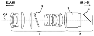
まず、本発明の実施例1における結像光学系について説明する。図1は、本実施例における結像光学系の断面図である。結像光学系は、レンズユニット1と色合成部2(光路合成部)を備えて構成されている。レンズユニット1は複数の光学素子(レンズ)を備えて構成される。本実施例において、レンズユニット1は全14枚のレンズから構成されたレトロフォーカスタイプの単焦点レンズであり、第2レンズが非球面レンズ(両面)である。またレンズユニット1は、その内部(光路中)において、光軸OAに対して非対称な形状を有する補正手段5を備える。レンズユニット1は、例えば、画像パネル(液晶表示素子、光変調素子)で変調された光をスクリーン(投射面)に投射する。
First, the imaging optical system in
色合成部2は、バックフォーカスの領域内に設けられており、プリズム3と、光軸OAに対して45°傾けて配置された平板4(傾斜した平板)とを備えて構成されている。プリズム3としては、例えば、ダイクロイックプリズムなどの誘電体多層膜を三角柱で挟んで構成された色合成プリズムが用いられる。平板4としては、例えば、板状の反射型偏光板が用いられる。本実施例の平板4は平行平板であるが、これに限定されるものではなく、本実施例は他の形状を有する平板に対しても適用可能である。また、上述の補正手段5は、平板4の傾斜方向の断面(図1に示される断面)において、光軸OAに対して非対称な形状を有する。ここで、傾斜方向の断面とは、平板4の法線とレンズユニット1の光軸OAに平行な断面である。
The color synthesizing
表1は、本実施例における数値実施例である。表1において、面番号はスクリーン側(拡大側)より順に各レンズの面に付した番号、Rは曲率半径、dは面間隔(次の面との物理的間隔)、nd、νdはそれぞれガラス材料のd線の屈折率およびアッベ数を示している。θは、各面の傾き角度を光軸法線(光軸直交方向)に対して反時計回り方向の回転を正として度単位で示したものである。ここで、各面の傾き角度とは、各面の面頂点における面内方向(接線方向)と光軸直交方向のなす角度である。光軸を通り面番号の右側に「*」が付されている面は、以下の式(1)で表される非球面形状を有する。式中の係数A〜E、Kは、それぞれ表1に示されている。また式中のrは、レンズユニット1の光軸OAから径方向への距離、xはr=0の位置から光軸方向への距離を示す。
Table 1 shows numerical examples in the present embodiment. In Table 1, surface numbers are numbers assigned to the surfaces of the lenses in order from the screen side (enlargement side), R is a radius of curvature, d is a surface interval (physical interval with the next surface), n d and ν d are Each shows the refractive index and Abbe number of d-line of the glass material. θ represents the angle of inclination of each surface in degrees, with the counterclockwise rotation being positive with respect to the optical axis normal (optical axis orthogonal direction). Here, the inclination angle of each surface is an angle formed by the in-plane direction (tangential direction) at the surface vertex of each surface and the direction perpendicular to the optical axis. A surface passing through the optical axis and marked with “*” on the right side of the surface number has an aspherical shape represented by the following formula (1). The coefficients A to E and K in the equation are shown in Table 1, respectively. Further, r in the formula represents a distance from the optical axis OA of the
x=(r2/R)/[1+{1−(1+K)(r2/R2)}1/2]
+Ay4+By6+Cy8+Dy10+Ey12 … (1)
(表1)
f=29.7 ω=23.7° F/1.96
R d nd vd θ
OBJ ∞ 2240.00 0.00
1 46.778 2.50 1.805 25.3 0.00
2 22.634 4.24 0.00
3* 84.965 3.14 1.531 55.8 0.00
4* 58.947 10.43 0.00
5 -29.186 1.90 1.489 69.8 0.00
6 109.955 10.59 0.00
7 337.095 7.28 1.773 49.5 0.00
8 -48.773 14.45 0.00
9 76.566 4.99 1.820 30.6 0.00
10 -4422.323 12.00 0.00
11 ∞ 2.26 1.516 64.1 20.61
12 ∞ 26.60 21.29
13 -110.432 8.59 1.490 69.7 0.00
14 -20.675 1.90 1.761 50.3 0.00
15 -7528.397 0.94 0.00
16 -205.738 5.55 1.487 70.1 0.00
17 -25.389 0.50 0.00
18 ∞ 0.50 0.00
19 1286.096 1.90 1.710 31.4 0.00
20 22.866 7.72 1.487 70.1 0.00
21 -44.899 2.62 0.00
22 -25.233 1.90 1.683 35.6 0.00
23 54.681 4.55 1.508 67.7 0.00
24 -176.094 0.50 0.00
25 116.045 12.10 1.487 70.1 0.00
26 -32.760 0.50 0.00
27 108.396 4.84 1.805 25.3 0.00
28 -150.374 1.50 0.00
29 ∞ 30.88 1.516 64.1 0.00
30 ∞ 7.50 1.516 64.1 0.00
31 ∞ 22.00 0.00
32 ∞ 1.00 1.516 64.1 45.00
33 ∞ 0.00 45.00
34 ∞
IMG
K A B C D E
3 0.000e+000 3.943e-005 -6.465e-008 1.143e-010 7.165e-014 -3.857e-016
4 0.000e+000 3.566e-005 -8.188e-008 1.485e-010 -1.586e-014 -5.280e-016
本実施例において、補正手段5は、両面において曲率半径を持たない平板4の傾斜方向の断面(紙面方向)において、所定の頂角を有する所謂クサビ状の断面を有する板状素子(クサビ板)である。本実施例において、所定の頂角は0.68°であるが、これに限定されるものではなく、必要に応じて適切な角度に設定される。すなわち補正手段5は、縮小側(縮小共役側)から離れるに従って薄くなり、縮小側に近づくに従って厚くなる平板である。ここで縮小側とは、液晶表示素子などの画像パネル側である。
x = (r 2 / R) / [1+ {1- (1 + K) (r 2 / R 2 )} 1/2 ]
+ Ay 4 + By 6 + Cy 8 + Dy 10 + Ey 12 (1)
(Table 1)
f = 29.7 ω = 23.7 ° F / 1.96
R d nd vd θ
OBJ ∞ 2240.00 0.00
1 46.778 2.50 1.805 25.3 0.00
2 22.634 4.24 0.00
3 * 84.965 3.14 1.531 55.8 0.00
4 * 58.947 10.43 0.00
5 -29.186 1.90 1.489 69.8 0.00
6 109.955 10.59 0.00
7 337.095 7.28 1.773 49.5 0.00
8 -48.773 14.45 0.00
9 76.566 4.99 1.820 30.6 0.00
10 -4422.323 12.00 0.00
11 ∞ 2.26 1.516 64.1 20.61
12 ∞ 26.60 21.29
13 -110.432 8.59 1.490 69.7 0.00
14 -20.675 1.90 1.761 50.3 0.00
15 -7528.397 0.94 0.00
16 -205.738 5.55 1.487 70.1 0.00
17 -25.389 0.50 0.00
18 ∞ 0.50 0.00
19 1286.096 1.90 1.710 31.4 0.00
20 22.866 7.72 1.487 70.1 0.00
21 -44.899 2.62 0.00
22 -25.233 1.90 1.683 35.6 0.00
23 54.681 4.55 1.508 67.7 0.00
24 -176.094 0.50 0.00
25 116.045 12.10 1.487 70.1 0.00
26 -32.760 0.50 0.00
27 108.396 4.84 1.805 25.3 0.00
28 -150.374 1.50 0.00
29 ∞ 30.88 1.516 64.1 0.00
30 ∞ 7.50 1.516 64.1 0.00
31 ∞ 22.00 0.00
32 ∞ 1.00 1.516 64.1 45.00
33 ∞ 0.00 45.00
34 ∞
IMG
KABCDE
3 0.000e + 000 3.943e-005 -6.465e-008 1.143e-010 7.165e-014 -3.857e-016
4 0.000e + 000 3.566e-005 -8.188e-008 1.485e-010 -1.586e-014 -5.280e-016
In the present embodiment, the correcting
補正手段5は、このような板状素子からなり、第5レンズと第6レンズとの間に平板4と同じ方向(同じ傾斜方向)に20°程度傾けて配置されている。軸上光束は、第5レンズを通過した後、第6レンズに向かう際に収束光となる。このため、特に上側光線が補正手段5を通過した後に下方向に向きを変えて進む。このように軸上光束が縮小側に向かって収束する位置において、補正手段5は平板4と同じ方向に傾けて配置されている。これにより、図1の断面における光束のピント位置(収束位置)を紙面左方向(縮小側から拡大側へ向かう方向)に移動させることができる。この断面における光束は、平板4によってピント位置が右方向(拡大側から縮小側へ向かう方向)に移動するため、補正手段5はこの光束の移動を相殺する。
The correcting means 5 is composed of such a plate-like element, and is disposed between the fifth lens and the sixth lens so as to be inclined by about 20 ° in the same direction (same inclination direction) as the
一方、高い画角(大きな画角)を有する光束は、周辺光量落ちにより軸上光束に比べて細くなり、平板4による非点収差の発生量も少ない。しかし、クサビ板である補正手段5が光軸OAに対して傾けて配置されているため、軸外光束は補正手段5に浅い角度で入射し、適度な補正量が得られる。また、クサビ板である補正手段5が傾けて配置されていることにより、上側光線と下側光線との間で屈折角に差が生じ、平板4で生じる上下非対称のスキュー光線の収差を補正することもできる。すなわち、レンズユニット1の内部に補正手段5を光軸OAに対して傾けて配置することで、全像高の収差を同時に補正することが可能となる。
On the other hand, a light beam having a high field angle (large field angle) becomes thinner than an axial light beam due to a decrease in peripheral light amount, and the amount of astigmatism generated by the
図2は、本実施例における結像光学系の結像性能を示すスポットダイアグラム図である。図2のスポットダイアグラム図は、イメージサークル中において、画像パネル(画像素子)の任意の5点(A)〜(E)のデフォーカス特性を示している。点(A)〜(E)は、画像パネルが50%シフトした場合の(A)画面下、(B)画面中心、(C)画面上、(4)画面横下、(E)画面横上の位置を示している。横軸はデフォーカス方向を示し、図中の左側がベストピント位置に対して拡大側(−)、図中の右側が縮小側(+)にそれぞれデフォーカスした場合のスポットダイアグラムを示している。 FIG. 2 is a spot diagram showing the imaging performance of the imaging optical system in the present embodiment. The spot diagram diagram of FIG. 2 shows the defocus characteristics of any five points (A) to (E) of the image panel (image element) in the image circle. Points (A) to (E) are (A) screen bottom, (B) screen center, (C) screen top, (4) screen bottom bottom, and (E) screen top top when the image panel is shifted by 50%. Indicates the position. The horizontal axis indicates the defocus direction, and the left side in the figure shows a spot diagram when the focus is defocused to the enlargement side (-) with respect to the best focus position, and the right side in the figure shows the defocus side (+).
続いて、比較例としての結像光学系について説明する。図12および図13はそれぞれ、本実施例の結像光学系から補正手段5を取り除いたレンズユニット100を用いた場合の断面図およびスポットダイアグラム図である。図13に示されるように、バランスピント位置におけるスポットについても、上下非対称の収差が発生しているため円形のスポットでなくおにぎり状の形状となっている。すなわち、補正手段を備えていない結像光学系では、結像性能が劣化する。図2と図13とを比較すると、補正手段5により結像光学系の結像性能が改善していることがわかる。
Subsequently, an imaging optical system as a comparative example will be described. FIGS. 12 and 13 are a sectional view and a spot diagram, respectively, in the case of using the
本実施例において、補正手段5はレンズユニット1の内部の第5レンズと第6レンズとの間に配置されているが、これに限定されるものではない。補正手段5は、レンズユニット1の内部の他の位置に配置した場合でも、本実施例と同様の補正効果を得ることができる。また、補正手段5の傾斜角度やクサビ板の頂角についても、レンズ系(レンズユニット)の設計に応じて異ならせてもよい。補正手段5をレンズユニット1の内部のいずれの位置に配置するか、また、補正手段5の傾斜角度や傾斜方向などは、レンズ系の設計に応じて適宜変更可能である。
In the present embodiment, the correcting
本実施例では、軸上光束が縮小側に向かって収束する位置に補正手段5を配置しているが、逆に、軸上光束が拡大側(拡大共役側)に向かって収束する位置に補正手段5を配置する場合、補正手段5は平板4と逆方向に傾けて配置される。
In this embodiment, the correcting
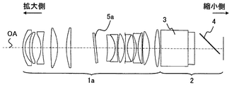
次に、本発明の実施例2における結像光学系について説明する。図3は、本実施例における結像光学系の断面図である。本実施例の結像光学系は、レンズユニット1aの内部に配置された補正手段5aが0.59°の頂角を有し、光軸OAに対して6°程度傾けて配置されたクサビ板である。更に、補正手段5aの縮小側の面は、平板4の傾斜方向の断面(図3に示される断面)において曲率半径を有するシリンダレンズ面(シリンダ面)である。本実施例の結像光学系は、実施例1の結像光学系にシリンダレンズ面を設けたことにより、スキュー光線の補正と像面倒れの補正をより効果的に実現でき、さらに高い性能を得ることができる。
Next, an image forming optical system according to
表2は、本実施例における数値実施例である。面番号の右側にcが付記されている面は、図3の断面方向に曲率半径を有し、それに直交する方向には曲率半径を有していないシリンダレンズ面であることを示している。 Table 2 shows numerical examples in this embodiment. A surface with c added to the right side of the surface number indicates a cylinder lens surface having a radius of curvature in the cross-sectional direction of FIG. 3 and not having a radius of curvature in a direction perpendicular thereto.
(表2)
f=31.9 ω=22.2° F/1.96
R d nd vd θ
OBJ ∞ 2240.00 0.00
1 38.818 2.50 1.805 25.4 0.00
2 21.771 5.21 0.00
3* 103.055 2.80 1.531 55.8 0.00
4* 54.624 9.91 0.00
5 -29.461 2.00 1.487 70.2 0.00
6 91.290 9.28 0.00
7 229.899 7.68 1.772 49.5 0.00
8 -48.773 10.10 0.00
9 72.586 4.89 1.799 29.8 0.00
10 1031.063 26.71 0.00
11 ∞ 2.18 1.516 64.1 5.80
12c -10709.183 12.60 6.39
13 -129.975 8.89 1.487 70.2 0.00
14 -22.152 2.00 1.740 52.6 0.00
15 93.129 1.09 0.00
16 72.300 7.49 1.487 70.2 0.00
17 -29.542 0.50 0.00
18 ∞ 0.50 0.00
19 719.032 2.00 1.737 32.2 0.00
20 26.212 7.81 1.487 70.2 0.00
21 -51.442 2.61 0.00
22 -28.769 2.00 1.647 33.7 0.00
23 46.424 4.53 1.516 64.1 0.00
24 1170.261 0.50 0.00
25 107.362 7.75 1.487 70.2 0.00
26 -36.166 6.15 0.00
27 105.088 5.29 1.805 25.4 0.00
28 -122.001 1.50 0.00
29 ∞ 30.88 1.516 64.1 0.00
30 ∞ 7.50 1.516 64.1 0.00
31 ∞ 22.00 0.00
32 ∞ 1.00 1.516 64.1 45.00
33 ∞ 0.00 45.00
34 ∞
IMG ∞
K A B C D E
3 0.000e+000 3.788e-005 -7.495e-008 1.209e-010 1.145e-014 -4.033e-016
4 0.000e+000 3.318e-005 -8.717e-008 1.206e-010 -6.650e-014 -4.813e-016
図4は、本実施例の結像性能を示すスポットダイアグラム図である。実施例1(図2)に比べると、シリンダ面という自由度が増したため、より高いレベルの補正が可能となる。
(Table 2)
f = 31.9 ω = 22.2 ° F / 1.96
R d nd vd θ
OBJ ∞ 2240.00 0.00
1 38.818 2.50 1.805 25.4 0.00
2 21.771 5.21 0.00
3 * 103.055 2.80 1.531 55.8 0.00
4 * 54.624 9.91 0.00
5 -29.461 2.00 1.487 70.2 0.00
6 91.290 9.28 0.00
7 229.899 7.68 1.772 49.5 0.00
8 -48.773 10.10 0.00
9 72.586 4.89 1.799 29.8 0.00
10 1031.063 26.71 0.00
11 ∞ 2.18 1.516 64.1 5.80
12c -10709.183 12.60 6.39
13 -129.975 8.89 1.487 70.2 0.00
14 -22.152 2.00 1.740 52.6 0.00
15 93.129 1.09 0.00
16 72.300 7.49 1.487 70.2 0.00
17 -29.542 0.50 0.00
18 ∞ 0.50 0.00
19 719.032 2.00 1.737 32.2 0.00
20 26.212 7.81 1.487 70.2 0.00
21 -51.442 2.61 0.00
22 -28.769 2.00 1.647 33.7 0.00
23 46.424 4.53 1.516 64.1 0.00
24 1170.261 0.50 0.00
25 107.362 7.75 1.487 70.2 0.00
26 -36.166 6.15 0.00
27 105.088 5.29 1.805 25.4 0.00
28 -122.001 1.50 0.00
29 ∞ 30.88 1.516 64.1 0.00
30 ∞ 7.50 1.516 64.1 0.00
31 ∞ 22.00 0.00
32 ∞ 1.00 1.516 64.1 45.00
33 ∞ 0.00 45.00
34 ∞
IMG ∞
KABCDE
3 0.000e + 000 3.788e-005 -7.495e-008 1.209e-010 1.145e-014 -4.033e-016
4 0.000e + 000 3.318e-005 -8.717e-008 1.206e-010 -6.650e-014 -4.813e-016
FIG. 4 is a spot diagram showing the imaging performance of the present embodiment. Compared to the first embodiment (FIG. 2), the degree of freedom of the cylinder surface is increased, so that a higher level of correction is possible.
次に、本発明の実施例3における結像光学系について説明する。図5は、本実施例における結像光学系の断面図である。本実施例の結像光学系では、レンズユニット1bの内部に設けられた補正手段5bが独立した素子としてではなく一つのレンズ面として設けられている点で、実施例1、2と異なる。
Next, an image forming optical system according to
本実施例の補正手段5bは、第6レンズの拡大側面を自由曲面とすることで達成される。自由曲面とは、光軸OAに対して回転対称でない曲面である。本実施例の自由曲面は、光軸OAから同じ距離の座標位置における自由曲面レンズの厚さが図5中の光軸OAよりも上側で薄く、かつ光軸OAよりも下側で厚くなる曲面である。 The correcting means 5b of the present embodiment is achieved by making the enlarged side surface of the sixth lens a free-form surface. A free-form surface is a curved surface that is not rotationally symmetric with respect to the optical axis OA. The free-form surface of the present embodiment is a curved surface in which the thickness of the free-form surface lens at the coordinate position at the same distance from the optical axis OA is thinner on the upper side than the optical axis OA in FIG. 5 and thicker on the lower side than the optical axis OA. It is.
本実施例における補正手段5bの形状(自由曲面)は、以下の式(2)で表される。zはr=0の位置から光軸方向への距離、rはレンズユニット1bの光軸OAから径方向への距離を示す。また、yは光軸OAに垂直でかつ図5の断面方向(紙面方向)への光軸OAからの距離、xは光軸OAに垂直でかつyと直交する方向(紙面直交方向)への光軸OAからの距離を示す。これらは、光軸上をゼロとする座標系である。
The shape (free curved surface) of the correction means 5b in the present embodiment is expressed by the following equation (2). z indicates the distance from the position of r = 0 in the optical axis direction, and r indicates the distance in the radial direction from the optical axis OA of the
z=(r2/R)/[1+{1−(1+K)(r2/R2)}1/2]
+C3y+C4x2+C6y2 … (2)
式(2)において、yは偶数次、奇数次の両方を含む。すなわち、図5の断面方向(紙面方向)で上下非対称な形状になることを示す。一方、xは偶数次の項のみを含む。すなわち、紙面直交方向については完全に対称な形状を有する。
z = (r 2 / R) / [1+ {1- (1 + K) (r 2 / R 2 )} 1/2 ]
+ C 3 y + C 4 x 2 + C 6 y 2 (2)
In equation (2), y includes both even and odd orders. That is, it shows that the shape is asymmetric in the vertical direction in the cross-sectional direction (paper surface direction) of FIG. On the other hand, x includes only even-order terms. That is, it has a completely symmetric shape in the direction orthogonal to the paper surface.
表3は、本実施例における数値実施例である。面番号の右側にfが付記されている面は、上記で定義される自由曲面であることを示している。 Table 3 shows numerical examples in this embodiment. A surface with f appended to the right side of the surface number indicates that it is a free-form surface as defined above.
(表3)
f=31.3 ω=22.6° F/1.96
R d nd vd θ
OBJ ∞ 2240.00 0.00
1 46.971 2.50 1.805 25.4 0.00
2 21.875 5.13 0.00
3* 138.000 2.85 1.531 55.8 0.00
4* 91.097 8.82 0.00
5 -29.226 2.00 1.487 70.2 0.00
6 97.786 9.99 0.00
7 211.696 7.21 1.772 49.5 0.00
8 -48.773 18.61 0.00
9 64.723 6.27 1.805 25.4 0.00
10 287.445 38.17 0.00
11f -109.149 6.32 1.487 70.2 0.00
12 -22.187 2.00 1.806 40.9 0.00
13 -340.028 1.58 0.00
14 1355.802 6.69 1.487 70.2 0.00
15 -28.869 0.50 0.00
16 ∞ 0.50 0.00
17 150.894 2.00 1.672 32.0 0.00
18 24.611 7.72 1.487 70.2 0.00
19 -79.498 3.21 0.00
20 -29.813 2.00 1.720 34.7 0.00
21 56.722 3.91 1.487 70.2 0.00
22 634.390 0.50 0.00
23 109.755 7.62 1.487 70.2 0.00
24 -35.916 3.76 0.00
25 125.661 5.13 1.805 25.4 0.00
26 -97.876 1.50 0.00
27 ∞ 30.88 1.516 64.1 0.00
28 ∞ 7.50 1.516 64.1 0.00
29 ∞ 22.00 0.00
30 ∞ 1.00 1.516 64.1 45.00
31 ∞ 0.00 45.00
32 ∞
IMG ∞
K A B C D E
3 0.000e+000 3.927e-005 -6.522e-008 1.316e-010 8.978e-015 -5.159e-016
4 0.000e+000 3.337e-005 -7.495e-008 1.337e-010 -6.389e-014 -6.378e-016
K C3 C4 C6
11 0.000e+000 0.0085 -8.388e-005 -1.967e-005
図6は、本実施例における結像光学系の結像性能を示すスポットダイアグラム図である。実施例1、2に比べると、補正手段として独立した素子を増やす必要がないため、スペースの節約ができ、小型の結像光学系を容易に得ることが可能である。
(Table 3)
f = 31.3 ω = 22.6 ° F / 1.96
R d nd vd θ
OBJ ∞ 2240.00 0.00
1 46.971 2.50 1.805 25.4 0.00
2 21.875 5.13 0.00
3 * 138.000 2.85 1.531 55.8 0.00
4 * 91.097 8.82 0.00
5 -29.226 2.00 1.487 70.2 0.00
6 97.786 9.99 0.00
7 211.696 7.21 1.772 49.5 0.00
8 -48.773 18.61 0.00
9 64.723 6.27 1.805 25.4 0.00
10 287.445 38.17 0.00
11f -109.149 6.32 1.487 70.2 0.00
12 -22.187 2.00 1.806 40.9 0.00
13 -340.028 1.58 0.00
14 1355.802 6.69 1.487 70.2 0.00
15 -28.869 0.50 0.00
16 ∞ 0.50 0.00
17 150.894 2.00 1.672 32.0 0.00
18 24.611 7.72 1.487 70.2 0.00
19 -79.498 3.21 0.00
20 -29.813 2.00 1.720 34.7 0.00
21 56.722 3.91 1.487 70.2 0.00
22 634.390 0.50 0.00
23 109.755 7.62 1.487 70.2 0.00
24 -35.916 3.76 0.00
25 125.661 5.13 1.805 25.4 0.00
26 -97.876 1.50 0.00
27 ∞ 30.88 1.516 64.1 0.00
28 ∞ 7.50 1.516 64.1 0.00
29 ∞ 22.00 0.00
30 ∞ 1.00 1.516 64.1 45.00
31 ∞ 0.00 45.00
32 ∞
IMG ∞
KABCDE
3 0.000e + 000 3.927e-005 -6.522e-008 1.316e-010 8.978e-015 -5.159e-016
4 0.000e + 000 3.337e-005 -7.495e-008 1.337e-010 -6.389e-014 -6.378e-016
K C3 C4 C6
11 0.000e + 000 0.0085 -8.388e-005 -1.967e-005
FIG. 6 is a spot diagram showing the imaging performance of the imaging optical system in the present embodiment. Compared to the first and second embodiments, it is not necessary to increase the number of independent elements as correction means, so that space can be saved and a small imaging optical system can be easily obtained.
なお本実施例の自由曲面は第6レンズに形成されているが、これに限定されるものではなく、複数のレンズのいずれか一つに形成されていればよい。 Although the free curved surface of the present embodiment is formed on the sixth lens, it is not limited to this, and it may be formed on any one of a plurality of lenses.
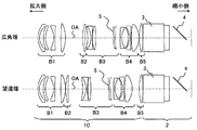
次に、本発明の実施例4における結像光学系について説明する。図7は、本実施例における結像光学系の断面図である。本実施例の結像光学系は、全13枚のレンズで構成された5群ズームレンズ(レンズユニット1c)であり、各レンズ群は、拡大側より順に、負、正、正、正、正の屈折力を有する。全13枚のレンズ中、第2レンズは非球面レンズ(両面)である。図7には、広角端と望遠端のそれぞれの場合におけるレンズ群の配置を示している。ズーミングに際し、第1レンズ群B1および第5レンズ群B5は固定であり、第2レンズ群B2、第3レンズ群B3、および、第4レンズ群B4が移動する。主たる変倍群は第2レンズ群B2である。本実施例の補正手段5は第3レンズ群B3に配置されており、変倍に際しては第3レンズ群B3の軌跡で移動する。すなわち補正手段5は、ズーミングに際して光軸方向に移動可能に構成されている。なお、本実施例における補正手段5は実施例1と同じ構成である。 Next, an image forming optical system according to Example 4 of the present invention will be described. FIG. 7 is a cross-sectional view of the imaging optical system in the present embodiment. The imaging optical system of the present embodiment is a five-group zoom lens (lens unit 1c) composed of a total of 13 lenses, and each lens group is negative, positive, positive, positive, positive in order from the magnification side. Have a refractive power of. Of all 13 lenses, the second lens is an aspheric lens (both sides). FIG. 7 shows the arrangement of lens groups in each of the wide-angle end and the telephoto end. During zooming, the first lens unit B1 and the fifth lens unit B5 are fixed, and the second lens unit B2, the third lens unit B3, and the fourth lens unit B4 move. The main variable power group is the second lens group B2. The correcting means 5 of this embodiment is disposed in the third lens unit B3, and moves along the locus of the third lens unit B3 during zooming. That is, the correction means 5 is configured to be movable in the optical axis direction during zooming. The correction means 5 in this embodiment has the same configuration as that in the first embodiment.
表4は、本実施例における数値実施例である。表中zが付記されている面間隔は、ズーミングに伴い変化する量である。 Table 4 shows numerical examples in this embodiment. The inter-surface spacing with z in the table is an amount that changes with zooming.
(表4)
f=29.5〜33.4〜34.5
ω=23.7°〜21.4°〜20.7°
F/1.96〜2.0〜2.02
r d nd vd θ
OBJ ∞ 2240.00 0.00
1 32.373 2.20 1.808 22.7 0.00
2 20.800 6.19 0.00
3* 69.391 2.99 1.531 55.8 0.00
4* 42.450 11.95 0.00
5 -29.466 2.00 1.496 81.5 0.00
6 240.972 8.69 0.00
7 227.310 6.91 1.785 44.2 0.00
8 -48.773 25.93z 0.00
9 92.573 3.45 1.749 35.3 0.00
10 357.123 3.65z 0.00
11 -69.678 4.93 1.603 60.6 0.00
12 -28.371 2.00 1.720 41.9 0.00
13 167.805 0.50 0.00
14 79.227 4.84 1.805 25.4 0.00
15 -116.245 26.22 0.00
16 ∞ 2.16 1.516 64.1 3.17
17c -9631.811 0.50 3.73
18 ∞ 7.38z 0.00
19 443.594 2.00 1.805 25.4 0.00
20 26.681 9.77 1.487 70.2 0.00
21 -31.031 1.93 0.00
22 -25.541 2.00 1.647 33.7 0.00
23 15619.549 0.50 0.00
24 103.428 11.17 1.496 81.5 0.00
25 -33.095 0.50z 0.00
26 87.025 4.65 1.808 22.7 0.00
27 -413.582 1.50 0.00
28 ∞ 30.88 1.516 64.1 0.00
29 ∞ 7.50 1.516 64.1 0.00
30 ∞ 22.00 0.00
31 ∞ 1.00 1.516 64.1 45.00
32 ∞ 0.00 45.00
33 ∞
IMG ∞
W M T
d 8 25.93 6.11 0.50
d10 3.65 18.52 21.83
d18 7.38 5.16 4.80
d25 0.50 7.66 10.33
K A B C D E
3 0.000e+000 3.286e-005 -6.573e-008 1.443e-010 -5.886e-014 -2.532e-016
4 0.000e+000 2.826e-005 -8.108e-008 1.462e-010 -7.392e-014 -5.541e-016
図8は、本実施例における結像光学系の結像性能を示すスポットダイアグラム図である。結像光学系をズームレンズとして用いた場合でも、補正手段が効果的に結像性能を改善することがわかる。
(Table 4)
f = 29.5-33.4-34.5
ω = 23.7 ° -21.4 ° -20.7 °
F / 1.96 ~ 2.0 ~ 2.02
rd nd vd θ
OBJ ∞ 2240.00 0.00
1 32.373 2.20 1.808 22.7 0.00
2 20.800 6.19 0.00
3 * 69.391 2.99 1.531 55.8 0.00
4 * 42.450 11.95 0.00
5 -29.466 2.00 1.496 81.5 0.00
6 240.972 8.69 0.00
7 227.310 6.91 1.785 44.2 0.00
8 -48.773 25.93z 0.00
9 92.573 3.45 1.749 35.3 0.00
10 357.123 3.65z 0.00
11 -69.678 4.93 1.603 60.6 0.00
12 -28.371 2.00 1.720 41.9 0.00
13 167.805 0.50 0.00
14 79.227 4.84 1.805 25.4 0.00
15 -116.245 26.22 0.00
16 ∞ 2.16 1.516 64.1 3.17
17c -9631.811 0.50 3.73
18 ∞ 7.38z 0.00
19 443.594 2.00 1.805 25.4 0.00
20 26.681 9.77 1.487 70.2 0.00
21 -31.031 1.93 0.00
22 -25.541 2.00 1.647 33.7 0.00
23 15619.549 0.50 0.00
24 103.428 11.17 1.496 81.5 0.00
25 -33.095 0.50z 0.00
26 87.025 4.65 1.808 22.7 0.00
27 -413.582 1.50 0.00
28 ∞ 30.88 1.516 64.1 0.00
29 ∞ 7.50 1.516 64.1 0.00
30 ∞ 22.00 0.00
31 ∞ 1.00 1.516 64.1 45.00
32 ∞ 0.00 45.00
33 ∞
IMG ∞
WMT
d 8 25.93 6.11 0.50
d10 3.65 18.52 21.83
d18 7.38 5.16 4.80
d25 0.50 7.66 10.33
KABCDE
3 0.000e + 000 3.286e-005 -6.573e-008 1.443e-010 -5.886e-014 -2.532e-016
4 0.000e + 000 2.826e-005 -8.108e-008 1.462e-010 -7.392e-014 -5.541e-016
FIG. 8 is a spot diagram showing the imaging performance of the imaging optical system in the present embodiment. It can be seen that even when the imaging optical system is used as a zoom lens, the correction means effectively improves imaging performance.
なお、本実施例においては、補正手段5が第3レンズ群B3とともに移動しているが、例えば独立した群として移動してもよい。この場合、移動群が一つ増加するが、例えば一つのカムの傾斜角を微妙に変化させれば補正手段の角度をズーミングに応じて変化させることができる。これにより、光線が補正手段を通過する角度をズーム位置に応じて最適化することができるため、より高倍のズーム系においても高い結像性能の実現が可能である。
In the present embodiment, the correcting
次に、本発明の実施例5における結像光学系について説明する。図9は、本実施例における結像光学系の断面図である。本実施例のレンズユニット1は、正リードのテレフォトタイプであり、全16枚のレンズから構成される単焦点レンズである。レンズユニット1dにおいて、非球面レンズは用いていない。補正手段5は、第10レンズと第11レンズの間に配置されている。表5は、本実施例における数値実施例である。
Next, an image forming optical system according to Example 5 of the present invention will be described. FIG. 9 is a cross-sectional view of the imaging optical system in the present embodiment. The
(表5)
f=58.9 ω=12.55° F/2.04
R d nd vd θ
OBJ ∞ 3770.00 0.00
1 394.213 11.00 1.654 39.6 0.00
2 -76.468 2.20 1.805 25.4 0.00
3 -366.123 0.10 0.00
4 79.961 7.23 1.834 42.7 0.00
5 -8466.787 20.85 0.00
6 -266.459 2.20 1.834 37.1 0.00
7 25.290 5.57 0.00
8 -32.976 3.00 1.516 64.1 0.00
9 87.334 6.32 1.805 25.4 0.00
10 -37.554 0.91 0.00
11 -32.355 3.00 1.749 35.2 0.00
12 -43.589 23.83 0.00
13 ∞ 0.94 0.00
14 -134.380 2.20 1.672 32.0 0.00
15 32.012 8.00 1.651 58.5 0.00
16 -692.615 0.10 0.00
17 100.901 6.21 1.805 25.4 0.00
18 -60.345 1.50 0.00
19 ∞ 2.79 1.516 64.1 8.17
20 ∞ 14.57 9.00
21 -121.273 2.20 1.805 25.4 0.00
22 32.562 9.94 1.487 70.2 0.00
23 -29.653 1.48 0.00
24 -26.474 2.00 1.740 27.7 0.00
25 44.987 8.40 1.712 53.8 0.00
26 -64.463 19.38 0.00
27 2683.493 6.50 1.805 25.4 0.00
28 -60.907 0.10 0.00
29 94.569 3.98 1.805 25.4 0.00
30 202.412 3.50 0.00
31 ∞ 30.88 1.516 64.1 0.00
32 ∞ 7.50 1.516 64.1 0.00
33 ∞ 22.00 0.00
34 ∞ 1.00 1.516 64.1 45.00
35 ∞ 0.00 45.00
36 ∞
IMG ∞
図10は、本実施例の結像性能を示すスポットダイアグラム図である。このように、テレフォトタイプのレンズ系においても、補正手段により結像性能を効果的に改善できることがわかる。
(Table 5)
f = 58.9 ω = 12.55 ° F / 2.04
R d nd vd θ
OBJ ∞ 3770.00 0.00
1 394.213 11.00 1.654 39.6 0.00
2 -76.468 2.20 1.805 25.4 0.00
3 -366.123 0.10 0.00
4 79.961 7.23 1.834 42.7 0.00
5 -8466.787 20.85 0.00
6 -266.459 2.20 1.834 37.1 0.00
7 25.290 5.57 0.00
8 -32.976 3.00 1.516 64.1 0.00
9 87.334 6.32 1.805 25.4 0.00
10 -37.554 0.91 0.00
11 -32.355 3.00 1.749 35.2 0.00
12 -43.589 23.83 0.00
13 ∞ 0.94 0.00
14 -134.380 2.20 1.672 32.0 0.00
15 32.012 8.00 1.651 58.5 0.00
16 -692.615 0.10 0.00
17 100.901 6.21 1.805 25.4 0.00
18 -60.345 1.50 0.00
19 ∞ 2.79 1.516 64.1 8.17
20 ∞ 14.57 9.00
21 -121.273 2.20 1.805 25.4 0.00
22 32.562 9.94 1.487 70.2 0.00
23 -29.653 1.48 0.00
24 -26.474 2.00 1.740 27.7 0.00
25 44.987 8.40 1.712 53.8 0.00
26 -64.463 19.38 0.00
27 2683.493 6.50 1.805 25.4 0.00
28 -60.907 0.10 0.00
29 94.569 3.98 1.805 25.4 0.00
30 202.412 3.50 0.00
31 ∞ 30.88 1.516 64.1 0.00
32 ∞ 7.50 1.516 64.1 0.00
33 ∞ 22.00 0.00
34 ∞ 1.00 1.516 64.1 45.00
35 ∞ 0.00 45.00
36 ∞
IMG ∞
FIG. 10 is a spot diagram showing the imaging performance of the present embodiment. Thus, it can be understood that the imaging performance can be effectively improved by the correcting means even in the telephoto type lens system.
次に、本発明の実施例6におけるプロジェクタについて説明する。図11は、本実施例のプロジェクタ(画像投射装置)の概略構成図である。本実施例のプロジェクタは、実施例1〜5のいずれか一つの結像光学系を備えた反射型液晶プロジェクタである。 Next, a projector according to a sixth embodiment of the invention will be described. FIG. 11 is a schematic configuration diagram of the projector (image projection apparatus) of the present embodiment. The projector according to the present embodiment is a reflective liquid crystal projector including any one of the imaging optical systems according to the first to fifth embodiments.
光源(不図示)から発した光束は、照明光学系12を経て光束分離素子13に入射し、入射光束は複数の光束に分離される。光束分離素子13は、例えばダイクロイックミラーの場合には波長(色)で光路を分離し、偏光ビームスプリッタの場合には偏光で光路を分離する。分離されたそれぞれの光束は、反射型偏光板14、15により反射される。反射型偏光板14、15は、波長以下のピッチで構成された格子構造を備え、格子方向の偏光は反射し、これと直交する方向の偏光は透過する特性を有する。一般に、照明光学系には偏光変換素子が配置されており、反射型偏光板14、15に入射する偏光は、反射偏光のみになるように構成されている。このため、分離した光束はそれぞれ反射型偏光板14、15にて反射し、反射型液晶素子16、17に入射する。
A light beam emitted from a light source (not shown) enters the light
反射型液晶素子16、17は、偏光を90°回転させ、反射型液晶素子16、17で反射した光束はそれぞれ、反射型偏光板14、15を透過して光束合成素子18に入射する。光束合成素子18は、光束分離素子13で分離された2つ光束を合成し、結像光学系である投射レンズ10に導く。本実施例のプロジェクタにおいて、分離光束はそれぞれ反射型偏光板14、15を透過するため、強い非点収差が発生する。このため、一般的な投射レンズ(結像光学系)では十分な結像性能が得られない。一方、本実施例のプロジェクタによれば、投射レンズ10として実施例1〜5のいずれか一つの結像光学系を用いているため、良好な投射像を得ることができる。
The reflective
本実施例においては、反射型の液晶素子を用いたがこれに限られず、透過型の液晶素子を用いたプロジェクタであっても本発明の効果を得ることができる。つまり、投射レンズと液晶素子との間に、光路を合成する平板が、投射レンズの光軸に垂直な方向に対して傾けて配置されるプロジェクタにおいて本発明を適用すれば、本実施例と同様の効果を得ることができる。 In the present embodiment, a reflective liquid crystal element is used, but the present invention is not limited to this, and the effect of the present invention can be obtained even with a projector using a transmissive liquid crystal element. That is, if the present invention is applied to a projector in which a flat plate for synthesizing an optical path is inclined between a projection lens and a liquid crystal element with respect to a direction perpendicular to the optical axis of the projection lens, the same as in the present embodiment. The effect of can be obtained.
以上、本発明の好ましい実施形態について説明したが、本発明はこれらの実施形態に限定されず、その要旨の範囲内で種々の変形及び変更が可能である。 As mentioned above, although preferable embodiment of this invention was described, this invention is not limited to these embodiment, A various deformation | transformation and change are possible within the range of the summary.
1 レンズユニット
2 色合成部
4 平板
5 補正手段
DESCRIPTION OF
Claims (6)
前記レンズユニットの光軸に対して傾けて配置された平板を備え、前記レンズユニットの縮小側に配置された光路合成部と、を有し、
前記レンズユニットは、前記平板の法線と前記光軸に平行な断面において、該光軸に対して非対称な形状を有する補正手段を備え、
前記補正手段は、縮小側から離れるに従って薄くなり、前記縮小側に近づくに従って厚くなるように構成されており、
前記補正手段は、軸上光束が前記縮小側に向かって収束する位置において、前記平板と同じ方向に傾けて配置されている、
ことを特徴とする結像光学系。 A lens unit having a plurality of optical elements;
Comprising a flat plate arranged to be inclined with respect to the optical axis of the lens unit, and an optical path combining unit arranged on the reduction side of the lens unit,
The lens unit includes correction means having an asymmetric shape with respect to the optical axis in a cross section parallel to the normal line of the flat plate and the optical axis,
The correction means is configured to become thinner as it moves away from the reduction side, and to become thicker as it approaches the reduction side,
The correction means is arranged to be inclined in the same direction as the flat plate at a position where the axial light beam converges toward the reduction side.
An imaging optical system characterized by that.
請求項1乃至5のいずれか1項に記載の結像光学系と、を有し、
前記結像光学系を介して、前記光変調素子からの光を投射面に投射する、
ことを特徴とする画像投射装置。 A light modulation element for modulating light from the light source;
An imaging optical system according to any one of claims 1 to 5,
Projecting light from the light modulation element onto a projection surface via the imaging optical system;
An image projection apparatus characterized by that.
Priority Applications (3)
| Application Number | Priority Date | Filing Date | Title |
|---|---|---|---|
| JP2011170692A JP5787662B2 (en) | 2011-08-04 | 2011-08-04 | Imaging optical system and image projection apparatus |
| CN201210269830.5A CN102914869B (en) | 2011-08-04 | 2012-07-31 | Imaging optical system, lens unit and image projection device |
| US13/563,939 US8864319B2 (en) | 2011-08-04 | 2012-08-01 | Imaging optical system, lens unit, and image projection apparatus |
Applications Claiming Priority (1)
| Application Number | Priority Date | Filing Date | Title |
|---|---|---|---|
| JP2011170692A JP5787662B2 (en) | 2011-08-04 | 2011-08-04 | Imaging optical system and image projection apparatus |
Publications (3)
| Publication Number | Publication Date |
|---|---|
| JP2013037044A JP2013037044A (en) | 2013-02-21 |
| JP2013037044A5 JP2013037044A5 (en) | 2014-07-31 |
| JP5787662B2 true JP5787662B2 (en) | 2015-09-30 |
Family
ID=47613299
Family Applications (1)
| Application Number | Title | Priority Date | Filing Date |
|---|---|---|---|
| JP2011170692A Expired - Fee Related JP5787662B2 (en) | 2011-08-04 | 2011-08-04 | Imaging optical system and image projection apparatus |
Country Status (3)
| Country | Link |
|---|---|
| US (1) | US8864319B2 (en) |
| JP (1) | JP5787662B2 (en) |
| CN (1) | CN102914869B (en) |
Families Citing this family (3)
| Publication number | Priority date | Publication date | Assignee | Title |
|---|---|---|---|---|
| JP2016038392A (en) * | 2014-08-05 | 2016-03-22 | キヤノン株式会社 | Projection optical system, and image projection device having the same |
| WO2017141753A1 (en) | 2016-02-15 | 2017-08-24 | コニカミノルタ株式会社 | Projection-type display device |
| US10663840B2 (en) | 2016-08-10 | 2020-05-26 | Konica Minolta, Inc. | Projection-type display device |
Family Cites Families (12)
| Publication number | Priority date | Publication date | Assignee | Title |
|---|---|---|---|---|
| JPH05100187A (en) * | 1991-10-04 | 1993-04-23 | Hitachi Ltd | Liquid crystal projector |
| JPH06337396A (en) | 1993-04-01 | 1994-12-06 | Casio Comput Co Ltd | Projector device |
| JP2000111862A (en) * | 1998-10-01 | 2000-04-21 | Sony Corp | Projection type display device |
| KR100584534B1 (en) * | 1999-04-26 | 2006-05-30 | 삼성전자주식회사 | Reflection type projector |
| JP4532647B2 (en) * | 2000-02-23 | 2010-08-25 | キヤノン株式会社 | Exposure equipment |
| BR0004290B1 (en) * | 2000-09-08 | 2009-01-13 | mirror cover fixing device to the control assembly. | |
| US6866404B2 (en) * | 2001-04-23 | 2005-03-15 | Ricoh Company, Ltd. | Illumination apparatus and a liquid crystal projector using the illumination apparatus |
| US7118222B2 (en) * | 2003-05-12 | 2006-10-10 | Seiko Epson Corporation | Optical device and protector |
| JP2005189635A (en) | 2003-12-26 | 2005-07-14 | Hitachi Ltd | Projection type image display device and optical unit used for it |
| US20090161073A1 (en) * | 2007-12-19 | 2009-06-25 | Victor Company Of Japan, Ltd. | Projection display apparatus |
| KR20090093666A (en) * | 2008-02-29 | 2009-09-02 | 삼성전자주식회사 | Projection optical system |
| JP5370764B2 (en) * | 2009-09-15 | 2013-12-18 | カシオ計算機株式会社 | Light source device and projector |
-
2011
- 2011-08-04 JP JP2011170692A patent/JP5787662B2/en not_active Expired - Fee Related
-
2012
- 2012-07-31 CN CN201210269830.5A patent/CN102914869B/en active Active
- 2012-08-01 US US13/563,939 patent/US8864319B2/en not_active Expired - Fee Related
Also Published As
| Publication number | Publication date |
|---|---|
| CN102914869A (en) | 2013-02-06 |
| CN102914869B (en) | 2016-12-21 |
| US8864319B2 (en) | 2014-10-21 |
| JP2013037044A (en) | 2013-02-21 |
| US20130033680A1 (en) | 2013-02-07 |
Similar Documents
| Publication | Publication Date | Title |
|---|---|---|
| JP6517294B2 (en) | Projection optical system | |
| US10754239B2 (en) | Projection optical assembly and projector device | |
| US9869849B2 (en) | Projection optical system and projection type display device | |
| US10338356B2 (en) | Projection optical system and projection type display device | |
| US10031324B2 (en) | Projection optical system and projection type display device | |
| JP5603292B2 (en) | Projection zoom lens and projection display device | |
| US8922903B2 (en) | Projection zoom lens and projection type display device | |
| WO2013118471A1 (en) | Optical system for projection, and projection-type display device | |
| US10386618B2 (en) | Projection optical system and projection type display device | |
| JP5642868B2 (en) | Projection zoom lens and projection display device | |
| JP5787662B2 (en) | Imaging optical system and image projection apparatus | |
| JP2007240731A (en) | Projection optical system and image projection device | |
| JP3695612B2 (en) | Zoom lens | |
| JP4551676B2 (en) | Zoom lens, image display device, imaging device | |
| JP2014142596A (en) | Zoom lens for projection |
Legal Events
| Date | Code | Title | Description |
|---|---|---|---|
| A521 | Request for written amendment filed |
Free format text: JAPANESE INTERMEDIATE CODE: A523 Effective date: 20140613 |
|
| A621 | Written request for application examination |
Free format text: JAPANESE INTERMEDIATE CODE: A621 Effective date: 20140613 |
|
| A977 | Report on retrieval |
Free format text: JAPANESE INTERMEDIATE CODE: A971007 Effective date: 20150115 |
|
| A131 | Notification of reasons for refusal |
Free format text: JAPANESE INTERMEDIATE CODE: A131 Effective date: 20150127 |
|
| A521 | Request for written amendment filed |
Free format text: JAPANESE INTERMEDIATE CODE: A523 Effective date: 20150330 |
|
| A131 | Notification of reasons for refusal |
Free format text: JAPANESE INTERMEDIATE CODE: A131 Effective date: 20150414 |
|
| A521 | Request for written amendment filed |
Free format text: JAPANESE INTERMEDIATE CODE: A523 Effective date: 20150611 |
|
| TRDD | Decision of grant or rejection written | ||
| A01 | Written decision to grant a patent or to grant a registration (utility model) |
Free format text: JAPANESE INTERMEDIATE CODE: A01 Effective date: 20150630 |
|
| A61 | First payment of annual fees (during grant procedure) |
Free format text: JAPANESE INTERMEDIATE CODE: A61 Effective date: 20150728 |
|
| R151 | Written notification of patent or utility model registration |
Ref document number: 5787662 Country of ref document: JP Free format text: JAPANESE INTERMEDIATE CODE: R151 |
|
| LAPS | Cancellation because of no payment of annual fees |