JP5785246B2 - Branch pipe mounting socket and branch pipe connection method - Google Patents
Branch pipe mounting socket and branch pipe connection method Download PDFInfo
- Publication number
- JP5785246B2 JP5785246B2 JP2013268322A JP2013268322A JP5785246B2 JP 5785246 B2 JP5785246 B2 JP 5785246B2 JP 2013268322 A JP2013268322 A JP 2013268322A JP 2013268322 A JP2013268322 A JP 2013268322A JP 5785246 B2 JP5785246 B2 JP 5785246B2
- Authority
- JP
- Japan
- Prior art keywords
- pipe
- branch pipe
- main
- lining material
- socket
- Prior art date
- Legal status (The legal status is an assumption and is not a legal conclusion. Google has not performed a legal analysis and makes no representation as to the accuracy of the status listed.)
- Active
Links
Images


Landscapes
- Branch Pipes, Bends, And The Like (AREA)
- Lining Or Joining Of Plastics Or The Like (AREA)
Description
本発明は枝管取付用ソケット及び枝管接続方法に係り、より詳しくは、樹脂製ライニング材で修復された本管に枝管を接続する際に適用する枝管取付用ソケット及び枝管接続方法に関する。 The present invention relates to a branch pipe mounting socket and a branch pipe connecting method, and more particularly, to a branch pipe mounting socket and a branch pipe connecting method applied when connecting a branch pipe to a main pipe restored with a resin lining material. About.
本発明は、老朽化した農業用水管、水道管、工業用水管、ガス管などの圧力パイプラインを修復するライニング工法に関するものである。
これまで老朽化した管を管ライニング工法により更正する方法が実施されており、枝管接続部は、管内に人が入れない場合は、接続先の本管を部分開削して接続部を開口させていた。管内に人が入れる場合は、管内に人が入り穿孔しする方法が採られていた。
しかし、本管にライニングを施した後に枝管接続部を開口すると、ライニング材と既設枝管の水密性が確保されていないため接続部で漏水が発生することがあった。
The present invention relates to a lining method for repairing pressure pipelines such as aging agricultural water pipes, water pipes, industrial water pipes, and gas pipes.
In the past, methods have been used to correct old pipes by pipe lining methods, and branch pipe connection parts can be opened by partially cutting the main pipe of the connection destination when people cannot enter the pipe. It was. When a person enters the tube, a method in which the person enters the tube and perforates is employed.
However, if the branch pipe connection portion is opened after the main pipe is lined, water leakage may occur at the connection portion because the watertightness between the lining material and the existing branch pipe is not ensured.
更に、枝管接続部を開口することにより、本管ライニングに欠損部が発生したと同様の状態となり、その部分の強度が低下する問題があった。
この強度低下は、本管径に対して枝管径が大きいほど激しく、地震により枝管接続部に大きい引張力が作用した場合は、枝管接続部の穿孔部が破断することもあった。
この問題解決のためには、本管ライニング材と確実に接着または一体結合し、かつ穿孔部の確実な補強が必要である。
Further, opening the branch pipe connecting portion causes a state similar to that in which a defective portion is generated in the main pipe lining, and there is a problem that the strength of the portion is lowered.
This drop in strength becomes more severe as the branch pipe diameter is larger than the main pipe diameter, and when a large tensile force acts on the branch pipe connection part due to an earthquake, the perforated part of the branch pipe connection part may break.
In order to solve this problem, it is necessary to securely bond or integrally bond with the main pipe lining material and to reinforce the perforated portion.
本発明は、本管ライニング材に枝管を接続する際に、本管ライニング材と枝管を確実に接着または結合し、かつ穿孔部の確実な補強ができる枝管取付用ソケット及び枝管接続方法の提供を目的とする。 The present invention relates to a branch pipe mounting socket and a branch pipe connection capable of securely bonding or bonding the main pipe lining material and the branch pipe and securely reinforcing the perforated portion when connecting the branch pipe to the main pipe lining material. The purpose is to provide a method.
本発明による枝管取付用ソケット(その1)は、既設本管と本管ライニング材からなる本管更生材に枝管を取付ける際使用されるつば付きの枝管取付用ソケットであって、前記枝管と同一の肉厚と内外径を有する管体からなる枝管ソケット本体部と、前記枝管ソケット本体部の1管端に前記枝管ソケット本体部と一体に形成される円環状の枝管ソケットのつば部と、からなり、前記枝管ソケットのつば部の前記枝管ソケット本体部に繋がらない1面が本管ライニング材の外周に密着する曲面を有し、つば部の体積が本管ライニング材の枝管と通じる穿孔部の穿孔板体積より大きく、かつ、つば部が本管ライニング材の外周を覆う面積が前記穿孔板の面積より大きく、前記既設本管が除去された部分の本管ライニング材の外周表面と前記枝管ソケットのつば部の1面を結合部とし、前記結合部に、主剤と硬化材を混合した2液型接着剤で、熱硬化性樹脂を塗布、含浸させた樹脂吸着材を接着すると共に、前記つば部を外側から押圧することにより、前記つば部が前記本管ライニング材に結合されることを特徴とする。
A branch pipe mounting socket according to the present invention (part 1) is a branch pipe mounting socket with a collar used when a branch pipe is attached to a main pipe rehabilitation material comprising an existing main pipe and a main pipe lining material. A branch pipe socket main body comprising a tube having the same thickness and inner / outer diameter as the branch pipe; and an annular branch integrally formed with the branch pipe socket main body at one pipe end of the branch pipe socket main body A flange portion of the tube socket, and one surface of the flange portion of the branch tube socket not connected to the branch tube socket main body has a curved surface closely contacting the outer periphery of the main pipe lining material, and the volume of the flange portion is The area of the portion where the existing main pipe is removed , the area of which the collar covers the outer periphery of the main lining material is larger than the area of the perforated plate, and is larger than the perforated plate volume of the perforated part communicating with the branch pipe of the pipe lining material The outer peripheral surface of the main lining material and the branch pipe One surface of the collar portion of the nut is a bonding portion, and the bonding portion is bonded with a resin adsorbent coated and impregnated with a thermosetting resin with a two-component adhesive in which a main agent and a curing material are mixed. The collar portion is coupled to the main lining material by pressing the collar portion from the outside .
本発明による枝管取付用ソケット(その2)は、既設本管と本管ライニング材からなる管更生材に枝管を取付ける際使用される半割管型の枝管取付用ソケットであって、前記枝管と同一の肉厚と内外径を有する管体からなる枝管ソケット本体部と、前記枝管ソケット本体部の1管端に前記枝管ソケット本体部と一体に形成される半割管と、前記半割管の円周方向両端部のボルト締結用のフランジと、からなり、前記本管ライニング材は、内周部の半割管を含む所定の長さ相当区間に熱硬化性樹脂が塗布されて肉厚が部分的に厚くされると共に、前記半割管は、所定の半割管長と既設本管と同じ内外径を有する半円弧状で、枝管ソケット本体部が取付けられていない半割管とにより、枝管設置部周辺の既設本管を所定長さ分、円周方向に亘って除去し露出させた本管ライニングの外周部を囲むようボルト締めされることを特徴とする。
A branch pipe mounting socket (part 2) according to the present invention is a half pipe type branch pipe mounting socket used when a branch pipe is attached to a pipe rehabilitation material comprising an existing main pipe and a main pipe lining material, A branch pipe socket main body comprising a tube having the same thickness and inner and outer diameter as the branch pipe, and a half pipe formed integrally with the branch pipe socket main body at one pipe end of the branch pipe socket main body And flanges for fastening bolts at both ends in the circumferential direction of the half pipe, and the main pipe lining material is a thermosetting resin in a section corresponding to a predetermined length including the half pipe at the inner circumference. The half pipe is a semicircular arc having a predetermined half pipe length and the same inner and outer diameter as the existing main pipe, and the branch pipe socket body is not attached. by a half tube, the existing main near the branch pipe installation portion predetermined length min, over the circumferential direction Characterized in that it is bolted to surround the outer periphery of the main pipe lining exposed Shi removed by.
本発明による第一の枝管接続方法は、既設本管と本管ライニング材からなる管更生材につば付きの枝管ソケットを適用して枝管を接続する枝管接続方法であって、前記管更生材の枝管接続部に枝管接続用の孔を穿孔する穿孔部形成段階と、前記管更生材の前記穿孔部周囲で前記枝管ソケットのつば部に相応する既設本管を除去する段階と、既設本管が除去された部分の前記管更生材の本管ライニング材の外周表面と前記枝管ソケットのつば部の1面を結合して結合部とする段階と、前記結合させたつば部を前記管更生材の外周方向に装着されたベルト状の締付具で固定する段階と、前記枝管ソケット本体部の1端と枝管本体を継ぎ手で結合する段階と、を含み、前記結合部に、主剤と硬化材を混合した2液型接着剤で、熱硬化性樹脂を塗布、含浸させた樹脂吸着材を接着すると共に、前記締付具で前記つば部を外側から押圧することにより、前記つば部が前記本管ライニング材に結合されることを特徴とする。
A first branch pipe connection method according to the present invention is a branch pipe connection method for connecting a branch pipe by applying a branch pipe socket with a collar to a pipe rehabilitation material composed of an existing main pipe and a main pipe lining material, A perforated part forming step for perforating a branch pipe connection hole in a branch pipe connecting part of the pipe rehabilitating material, and an existing main pipe corresponding to the collar part of the branch pipe socket around the perforated part of the pipe rehabilitating material is removed. Combining the outer peripheral surface of the main pipe lining material of the pipe rehabilitation material and the one surface of the collar part of the branch pipe socket to form a joint part, wherein the existing main pipe has been removed Fixing the collar portion with a belt-like fastener mounted in the outer circumferential direction of the pipe rehabilitation material, and coupling one end of the branch pipe socket main body portion and the branch pipe main body with a joint, Applying a thermosetting resin to the joint with a two-component adhesive in which a main agent and a curing material are mixed, Thereby bonding the dipped allowed resin adsorbent, by pressing the flange portion from the outside with fitting said clamping, wherein the flange portion is coupled to the main pipe liner bag.
前記枝管ソケットのつば部の他面の本管ライニング材の外周表面への押圧は、樹脂製半円リングのボルト締め、ステンレス製ワイヤロープ、金属製または樹脂製のベルトでの締め付けによることを特徴とする。
The pressure on the outer surface of the main lining material on the other side of the collar portion of the branch pipe socket is by bolting a resin semicircular ring, tightening with a stainless steel wire rope, metal or resin belt. Features.
本発明による第二の枝管接続方法は、既設本管と本管ライニング材からなる管更生材に半割管型の枝管ソケットを適用して枝管を接続する枝管接続方法であって、枝管設置部周辺の既設本管を所定長さ分、円周方向に亘って除去して本管ライニング材を露出させる段階と、既設本管除去部に相当する1対の半割型枠管を本管ライニング材の円周方向に設置する段階と、本管ライニング材の内周部に半割型枠管を含む所定の長さ相当区間に熱硬化性樹脂が塗布され、本管ライニング材の肉厚を部分的に厚くする段階と、前記熱硬化性樹脂を加熱し硬化させた後、1対の半割型枠管を本管ライニング材から取り外す段階と、前記本管ライニング材の枝管接続部に枝管接続用の孔を穿孔する穿孔部を形成する段階と、前記穿孔部に半割管型の枝管取付用ソケットを取り付け、半割管型の枝管取付用ソケットのフランジ部を締結する段階と、を含み、前記半割管は、所定の半割管長と既設本管と同じ内外径を有する半円弧状で、枝管ソケット本体部が取付けられていない半割管とにより本管ライニングの外周部を囲むようボルト締めされることを特徴とする。
A second branch pipe connection method according to the present invention is a branch pipe connection method for connecting a branch pipe by applying a half pipe type branch pipe socket to a pipe rehabilitation material comprising an existing main pipe and a main pipe lining material. , predetermined length min the existing main pipe around the branch pipe installation unit, comprising the steps of exposing the main pipe liner bag is removed over the circumferential direction, half mold a pair corresponding to the existing main removing portion A pipe is installed in the circumferential direction of the main lining material, and a thermosetting resin is applied to a section corresponding to a predetermined length including a half-shaped frame tube on the inner periphery of the main lining material, and the main lining a method to increase the thickness of the wood part, after curing by heating the thermosetting resin, the steps of removing the half mold tube pair from the main pipe liner bag, said main pipe liner bag Forming a perforated portion for perforating a branch pipe connection hole in the branch pipe connecting portion; and Attach the use sockets, the steps of fastening the flange portion of the half-tube type branch pipe mounting socket, only contains the half tube half have the same inner and outer diameter as the predetermined half pipe length and the existing main pipe It is arc-shaped and is bolted so as to surround the outer periphery of the main pipe lining with a half pipe to which the branch pipe socket main body is not attached.
前記本管ライニング材の外周表面と前記枝管ソケットの内周面の間にパッキンが挿入されていることを特徴とする。
A packing is inserted between the outer peripheral surface of the main pipe lining material and the inner peripheral surface of the branch pipe socket.
本発明による第三の枝管接続方法は、既設本管に本管ライニング材を取付けるとともに、既設枝管と枝管ライニング材からなる枝管更生材を既設本管に接続する枝管接続方法であって、前記既設本管の枝管接続部に枝管接続用の孔を穿孔する穿孔部形成段階と、樹脂未含浸の管状ライナー材の1端を前記穿孔部に通した後、先端を花弁状に切開いて枝管ライニング材のつば部とし、つば部の内外面に樹脂吸着材を貼り付けると共に、このつば部の1面を既設本管内周壁に押付ける段階と、前記ライナー材先端の花弁状に切開かれたつば部に熱硬化性樹脂を吸着させて硬化させる段階と、前記ライナー材のつば部を除く部分に熱硬化性樹脂を含浸させた後、管内に圧力バッグを挿入し圧力バッグ内に温水を供給して枝管ライニング材を硬化させる段階と、前記既設本管の所定の箇所から既設本管内に本管ライニング材をつば部の他面に重なるように挿入する段階と、地上から枝管を通して樹脂注入ホースが挿入され、前記樹脂注入ホースにより本管ライニング材の外周部に熱硬化性樹脂が注入されると共に、前記既設本管と本管ライニング材で枝管のつば部を挟み込み本管ライニング材を加圧することにより枝管のつば部を押圧する段階と、管内に圧力バッグを挿入し圧力バッグ内に温水を供給して本管ライニング材を加圧し本管ライニング材を硬化させる段階と、前記本管ライニング材が硬化された後、枝管接続部の本管ライニング材に流体通過用の孔を穿孔する段階と、を含み、前記つば部の体積が本管ライニング材の枝管と通じる穿孔部の穿孔板体積より大きく、かつ、つば部の1面と本管ライニング材の接触面積が前記穿孔板の面積より大きいことを特徴とする。
A third branch pipe connection method according to the present invention is a branch pipe connection method in which a main pipe lining material is attached to an existing main pipe, and a branch pipe renewal material composed of the existing branch pipe and the branch pipe lining material is connected to the existing main pipe. A perforated part forming step for perforating a branch pipe connecting hole in a branch pipe connecting part of the existing main pipe, and passing one end of the resin-impregnated tubular liner material through the perforated part; the flange portion of the branch pipe lining material Sekkaii to Jo, the paste resin adsorbent inner and outer surfaces of the flange portion, the steps of pressing the first surface of the flange portion to the existing present pipe wall, the liner material tip petals A step of adsorbing a thermosetting resin to the collar portion cut into a shape and curing the portion, and impregnating the portion of the liner material excluding the collar portion with the thermosetting resin, and then inserting a pressure bag into the tube Warm water is supplied inside to harden the branch lining material. A step, and inserting to overlap the other surface of the flange portion of the main pipe liner bag into the existing present tube from a predetermined position of the existing main pipe, the resin filler hose through the branch pipe from the ground is inserted, the resin injection A thermosetting resin is injected into the outer periphery of the main lining material by a hose, and the main pipe lining material is pressurized by sandwiching the collar portion of the branch pipe between the existing main pipe and the main lining material. Pressing the section, inserting a pressure bag into the pipe, supplying warm water into the pressure bag to pressurize the main lining material and curing the main lining material, and after the main lining material is cured Piercing a fluid passage hole in the main pipe lining material of the branch pipe connection portion, and the volume of the collar portion is larger than the perforated plate volume of the perforation portion communicating with the branch pipe of the main pipe lining material, and , Collar The contact area of the first surface and the main pipe liner bag being greater than the area of the perforated plate.
本発明によれば、枝管接続とともに本管ライニング材の穿孔部の補強がなされるため、枝管接続部の水密性とともに強度が確保できる。 According to the present invention, since the perforated portion of the main lining material is reinforced with the branch pipe connection, the strength can be secured together with the water tightness of the branch pipe connection portion.
本発明は、本管更生材1用の枝管ソケット5及び枝管接続方法に関するもので、枝管接続方法としては、枝管ソケット5を成形して、成形済の枝管ソケット5を使用する方法(実施例1,2)と、枝管用樹脂未含浸の管状ライナー材の1端を穿孔部10に通した後、先端を花弁状に切開いて枝管ライニング材3の枝管ソケットつば部7とし、ライナー材の枝管ソケットのつば部7を除く部分には熱硬化性樹脂を含浸させた後、硬化させて枝管ライニング材3とする方法(実施例3)がある。
以下、本発明について図面を参照して詳細に説明する。
The present invention relates to a
Hereinafter, the present invention will be described in detail with reference to the drawings.
図1は、本発明の実施例1によるつば付き枝管ソケット5の製造法を示す図、図2は、本発明の実施例1による本管ライニング材3に枝管ソケット5を適用して枝管4を接続する状況を示す本管更生材1の長手方向断面図、図3は、本発明の実施例1による本管ライニング材3に枝管ソケット5を適用して枝管4を接続する状況を示す本管更生材1の断面図である。
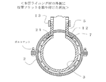
図4は、本発明の実施例2による本管ライニング材3の肉厚増加後の硬化状況を示す図、図5は、本発明の実施例2による本管ライニング材3の肉厚増加部硬化後に半割型枠管を取り外した状況を示す図、図6は、本発明の実施例2による半割管型の枝管ソケットを適用して枝管4を接続する状況を示す本管更生材長手方向の断面図、図7は、つば付き枝管ソケット5の断面図、図8は、穿孔板とつば付き枝管ソケット5のつば部の関係を示す図である。
図9は、本発明の実施例3によるつば付き枝管ライニング材22の硬化状況を示す図、図10は、本発明の実施例3による本管ライニング材3の反転挿入状況を示す図、図11は、 本発明の実施例3による本管ライニング材3の硬化状況を示す図である。
FIG. 1 is a diagram showing a manufacturing method of a flanged
FIG. 4 is a view showing a hardening state after the increase in the thickness of the
FIG. 9 is a diagram showing a curing state of the brim-
先ず、枝管ソケット5の構成と製造法について説明する。
図1に示す通り、枝管ソケット5は、本管更生材1に取付ける枝管4と同一の肉厚と内外径を有する管体からなる枝管ソケット本体6と、枝管ソケット本体6の1管端に枝管ソケット本体6と一体に形成される円環状の枝管ソケットのつば部7とからなり、円環状のつば部7の1面は本管ライニング材3の外周に密着する曲面を有する。
つば部7の体積は本管ライニング材3の枝管4と通じる穿孔部10の穿孔板20の体積より大きく、かつ、つば部7が本管ライニング材3の外周を覆う面積が穿孔板20の面積より大きいことを特徴とする。
ここで、穿孔板20は、本管更生材1に枝管4を取付けるための穿孔部10から切出された穿孔部10に相当する部分を言い、穿孔板20の体積は、穿孔部10の内径から算出した穿孔板20の面積と本管ライニング材3の肉厚から算定する。
First, the structure and manufacturing method of the
As shown in FIG. 1, the
The volume of the
Here, the
枝管4と本管更生材1の接合部において枝管4の端部にフランジ状に張り出したつば部7を設け本管更生材1と接続する方法は、従来より下水道、農業用水路、工業用水路、水道などの分野で周知の技術であった。
しかし、つば部の適正サイズについての知見はなく、過小なつば部による強度不足や、過大なつば部を設けることによる作業上の難点やコスト上昇などの問題があった。
そこで、本発明では、つば部7のサイズを明確な根拠に基づいて必要で十分なものにし、満足な効果を得られるようにしたものである。
The method of connecting the main
However, there is no knowledge about the appropriate size of the collar part, and there are problems such as insufficient strength due to an excessive collar part, difficulty in work due to providing an excessive collar part, and cost increase.
Therefore, in the present invention, the size of the
上記つば部7のサイズ決定に当たり、つば部7の体積と穿孔板20の体積の関係を設けた理由は以下の通りである。
既設本管2と本管ライニング材3からなる本管更生材1の殆どは、一定長さの老朽化した既設本管2に対して継手のない一体構造の樹脂製ライニング材が内張された構造となっている。
そして、枝管4を接続する場合には接続箇所に穿孔する必要があるが、穿孔により接続箇所の樹脂製ライニング材が強度低下を生じる問題があった。
そこで、穿孔部10周辺のライニング材の肉厚を増やすとともに、つば部7が本管ライニング材3の外周を覆う面積を穿孔板20の面積より大きくして強固に接合することで穿孔部10の強度を回復させることとした。
In determining the size of the
Most of the main
When the
Accordingly, the thickness of the lining material around the perforated
上記対策の効果は強度回復実験によっても確認することができた。
強度回復実験を各種条件で行った結果、穿孔部10周辺のライニング材の体積が穿孔により失われた部分である穿孔板20と同じ体積以上となるように穿孔部10周辺の肉厚を増やし、かつ、つば部7が本管ライニング材3の外周を覆う面積を穿孔板20の面積より大きくして、つば部7と本管ライニング材3を接着剤で強固に接合することで、強度が穿孔前の状態に回復することが判明した。
なお、接続部の補強法としては、枝管4の接続部の本管ライニング材3外周に半割型枠管15を設置し、半割型枠管15の内部の本管ライニング材3の肉厚を増やすなどして補強した後、半割型枠管15を取り外し、その場所に半割管18を取り付ける方法や、半割型枠管15を取り外した後本管ライニング材3を増厚する方法もある。
The effect of the above measures could be confirmed by a strength recovery experiment.
As a result of conducting the strength recovery experiment under various conditions, the thickness of the periphery of the
As a method of reinforcing the connecting portion, a half-shaped frame tube 15 is installed on the outer periphery of the
枝管ソケットの製造法は、図1に示す通りである。
先ず、枝管ソケット5の内径と同寸法の外径を有する管状の外周部と、既設本管2の内径及び本管ライニング材3の外径と同寸法の外径を有し、本管ライニング材3の外周に密着する曲面を有する枝管ソケット下型枠8の上に、枝管ソケット本体6相当部は枝管ソケット本体6と同じ肉厚、つば部7相当部は既設本管2と同じ肉厚の樹脂未吸着の不織布またはグラスファイバーを巻付け配置する。
そして、樹脂未吸着の不織布またはグラスファイバーに不飽和ポリエステル、ビニールエステル、エポキシ等の液状熱硬化性樹脂を吸着させる。
次に、枝管ソケット本体6の不織布またはグラスファイバーの外周部及びつば部7の不織布またはグラスファイバーの上に枝管ソケット上型枠9を重ね、
不織布またはグラスファイバーに吸着させた熱硬化性樹脂を硬化させる。
The manufacturing method of the branch pipe socket is as shown in FIG.
First, a tubular outer peripheral portion having the same outer diameter as the inner diameter of the
And liquid thermosetting resins, such as unsaturated polyester, vinyl ester, and epoxy, are made to adsorb | suck to the non-adsorbed nonwoven fabric or glass fiber.
Next, the branch pipe socket
The thermosetting resin adsorbed on the nonwoven fabric or glass fiber is cured.
つば部7の体積は、円環状つば部の表面積とつば部の肉厚から算定する。
穿孔板20は、本管更生材1に枝管4を取付けるための穿孔部10から切出された穿孔部10に相当する部分を言い、穿孔板20の面積は、穿孔部10の内径から算出し、穿孔板20の体積は、穿孔板20の面積と本管ライニング材3の肉厚から算定する。
The volume of the
The
次に、本発明の実施例1による本管ライニング材3に枝管ソケット5を適用して枝管4を接続する枝管接続方法について説明する。
本管ライニング材3は、不織布またはグラスファイバー等樹脂未含浸状態のライナー材を管状に加工し、内外面を樹脂フィルムで覆って気密状態とした後、液状の熱硬化性樹脂を含浸させて製造される。
Next, a branch pipe connection method for connecting the
The
実施例1では、
図2、3に示す通り、既設本管2と本管ライニング材3からなる本管更生材1の枝管接続部10に枝管接続用の孔11を穿孔して穿孔部10とする。
次に、管更生材の穿孔部10周囲で枝管ソケット5のつば部7に相応する既設本管2を除去する。
既設本管2が除去された部分の本管更生材1の本管ライニング材3の外周表面と枝管ソケット5のつば部7の1面を結合して結合部とし、結合させたつば部7を本管更生材1の外周方向に装着されたベルト状の締付具12で固定し、枝管ソケット本体6の1端と枝管4本体とを継手13で結合する。
In Example 1,
As shown in FIGS. 2 and 3, a branch pipe connection hole 11 is drilled in the branch
Next, the existing
The outer peripheral surface of the main
つば部7の内面または外面全体または一部に、主剤と硬化材を混合した2液型接着剤等で熱硬化性樹脂を塗布した樹脂吸着材が接着され、枝管ソケット5のつば部7の他面を押圧することで接合を強固なものとすることが出来る。
上記押圧は、樹脂製半円リングのボルト締め、ステンレス製ワイヤロープ、金属製または樹脂製のベルトでの締付けでもよい。
また、本管ライニング材3の外周表面と枝管ソケット5のつば部7の1面の間にはパッキンを挿入してもよい。
A resin adsorbent coated with a thermosetting resin, such as a two-component adhesive mixed with the main agent and a curing material, is adhered to the inner surface or the entire outer surface or a part of the
The pressing may be performed by bolting a resin semicircular ring, tightening with a stainless steel wire rope, a metal or resin belt.
Further, a packing may be inserted between the outer peripheral surface of the main
本発明の実施例2は、既設本管2と本管ライニング材3からなる本管更生材1に半割管18型の枝管ソケット5を適用して枝管4を接続する枝管接続方法である。
図4、5に示す通り、枝管接続部10周辺の既設本管2を所定長さ分円周方向亘って除去して本管ライニング材3を露出させる。
次に、既設本管2の除去部に相当する1対の半割型枠管15を本管ライニング材3の円周方向に設置し、本管ライニング材3の内周部に半割型枠管15の両管端から所定の長さ相当区間に本管ライニング材3の肉厚を部分的に厚くする熱硬化性樹脂を塗布する。具体的には、本管ライニング材3の肉厚の0.2乃至1.5倍の熱硬化性樹脂を塗布することが望ましい。
塗布された熱硬化性樹脂は、本管ライニング材3の内部に挿入した温水シャワーホース16からのシャワーで硬化させた後、1対の半割型枠管15を本管ライニング材3から取り外す。
本管ライニング材3を取り外した後、本管ライニング材3の枝管接続部10に枝管接続用の孔11を穿孔して穿孔部10を形成し、穿孔部10に半割管型18の枝管ソケット5を取り付け、半割管18型の枝管ソケット5のフランジ19を締結する。
As shown in FIGS. 4 and 5, the existing
Next, a pair of halved mold tubes 15 corresponding to the removed portions of the existing
The applied thermosetting resin is cured by a shower from a hot
After removing the main
枝管ソケット5の半割管18の体積と穿孔板20の体積との関係については、枝管ソケット5の半割管18の体積から本管ライニング材3の枝管4と通じる穿孔部10の穿孔板20の体積を減じた値が穿孔板20の体積より大きく、かつ、半割管18が本管ライニング材3の外周を覆う面積から穿孔板20の面積を減じた値が穿孔板20の面積より大きくなるようにする。
半割管18は、所定の半割管18の長さと既設本管2と同じ内外径を有する半円弧状で、枝管ソケット本体6が取付けられていない半割管18とにより本管ライニング材3の外周部を囲むようボルト締めされる。
Regarding the relationship between the volume of the
The
次に、本発明の実施例3による管状ライナー材の1端につば部7を形成して枝管4を接続する枝管接続方法について説明する。
図9乃至11に示す通り、この方法は、枝管用樹脂未含浸の管状ライナー材の1端を穿孔部10に通した後、先端を花弁状に切開いて枝管ライニング材22のつば部7とし、ライナー材のつば部7を除く部分には熱硬化性樹脂を含浸させた後、硬化させて枝管ライニング材22とする方法であり、既設本管2に本管ライニング材3を取付けるとともに、既設枝管4と枝管ライニング材22からなる枝管更生材25を既設本管2に接続するものである。
Next, a branch pipe connection method for connecting the
As shown in FIGS. 9 to 11, in this method, one end of a tubular liner material not impregnated with a branch pipe is passed through the perforated
先ず、既設本管2の枝管接続部10に枝管接続用の孔11を穿孔して穿孔部10を形成する。
樹脂未含浸の管状ライナー材の1端を穿孔部10に通した後、先端を花弁状に切開いて枝管ライニング材22のつば部7とし、このつば部7の1面を既設本管2の内周壁に押付け、ライナー材先端の花弁状に切開かれたつば部7に熱硬化性樹脂を吸着させて硬化させる。
そして、ライナー材のつば部7を除く部分に熱硬化性樹脂を含浸させた後、管内に圧力バッグ23を挿入し圧力バッグ23の内部に温水を供給して枝管ライニング材22を硬化させる。
First, the branch
After passing one end of the resin-impregnated tubular liner material through the perforated
And after impregnating a thermosetting resin in the part except the
次に、既設本管2の所定の箇所から既設本管2内部に本管ライニング材3をつば部7の他面に重なるように挿入する。
既設本管2につば部7を押し付けた状態で枝管4をライニングした後、既設本管2に本管ライニング材3を挿入し、地上から枝管4を通し本管ライニング材3の外周部に熱硬化性樹脂を注入する。
そして、既設本管2と本管ライニング材3で枝管4のつば部7を挟み込み本管ライニング材3を加圧することにより枝管4のつば部7を押圧する。
本管ライニング材3の管内には圧力バッグ23を挿入し圧力バッグ23内部に温水を供給して本管ライニング材3を加圧し本管ライニング材3を硬化させ、その後、枝管接続部10の本管ライニング材3に流体通過用の孔11を穿孔する。
つば部7の体積と本管ライニング材3の枝管4と通じる穿孔部10の穿孔板20の体積、及び、つば部7の1面と本管ライニング材3の接触面積と穿孔板20の面積の関係については先の枝管ソケット5の場合と同様である。
Next, the
After lining the
And the
A
The volume of the
1 本管更生材
2 既設本管
3 本管ライニング材
4 枝管、既設枝管
5 枝管ソケット
6 枝管ソケット本体
7 つば部
8 枝管ソケット下型枠
9 枝管ソケット上型枠
10 穿孔部、枝管接続部
11 孔
12 締付具
13 継手
14 パッキン
15 半割型枠管
16 温水シャワーホース
17 増厚部
18 半割管
19 フランジ
20 穿孔板
21 ドーナツ状樹脂吸着材
22 枝管ライニング材
23 圧力バッグ
24 樹脂注入ホース
25 枝管更生材
DESCRIPTION OF
14 Packing 15 Half-shaped
Claims (7)
前記枝管と同一の肉厚と内外径を有する管体からなる枝管ソケット本体部と、
前記枝管ソケット本体部の1管端に前記枝管ソケット本体部と一体に形成される円環状の枝管ソケットのつば部と、からなり、
前記枝管ソケットのつば部の前記枝管ソケット本体部に繋がらない1面が本管ライニング材の外周に密着する曲面を有し、つば部の体積が本管ライニング材の枝管と通じる穿孔部の穿孔板体積より大きく、かつ、つば部が本管ライニング材の外周を覆う面積が前記穿孔板の面積より大きく、
前記既設本管が除去された部分の本管ライニング材の外周表面と前記枝管ソケットのつば部の1面を結合部とし、前記結合部に、主剤と硬化材を混合した2液型接着剤で、熱硬化性樹脂を塗布、含浸させた樹脂吸着材を接着すると共に、前記つば部を外側から押圧することにより、前記つば部が前記本管ライニング材に結合されることを特徴とする枝管取付用ソケット。
A branch pipe mounting socket with a collar used when attaching a branch pipe to a main pipe rehabilitation material consisting of an existing main pipe and a main pipe lining material,
A branch pipe socket main body comprising a pipe body having the same thickness and inner and outer diameter as the branch pipe;
A collar portion of an annular branch pipe socket formed integrally with the branch pipe socket main body at one pipe end of the branch pipe socket main body;
One surface of the collar portion of the branch pipe socket that does not connect to the branch pipe socket main body has a curved surface that is in close contact with the outer periphery of the main pipe lining material, and the volume of the collar section communicates with the branch pipe of the main pipe lining material And the area where the collar covers the outer periphery of the main lining material is larger than the area of the perforated plate,
A two-component adhesive in which the outer peripheral surface of the main lining material at the portion where the existing main pipe has been removed and one surface of the collar portion of the branch pipe socket are used as a joint portion, and the main agent and the curing material are mixed in the joint portion. In this case, the resin adsorbent coated and impregnated with a thermosetting resin is bonded, and the collar portion is bonded to the main lining material by pressing the collar portion from the outside. Socket for tube mounting.
前記枝管と同一の肉厚と内外径を有する管体からなる枝管ソケット本体部と、
前記枝管ソケット本体部の1管端に前記枝管ソケット本体部と一体に形成される半割管と、
前記半割管の円周方向両端部のボルト締結用のフランジと、からなり、
前記本管ライニング材は、内周部の半割管を含む所定の長さ相当区間に熱硬化性樹脂が塗布されて肉厚が部分的に厚くされると共に、前記半割管は、所定の半割管長と既設本管と同じ内外径を有する半円弧状で、枝管ソケット本体部が取付けられていない半割管とにより、枝管設置部周辺の既設本管を所定長さ分、円周方向に亘って除去し露出させた本管ライニングの外周部を囲むようボルト締めされることを特徴とする枝管取付用ソケット。
A half pipe type socket for mounting a branch pipe used when attaching a branch pipe to a pipe rehabilitation material comprising an existing main pipe and a main pipe lining material,
A branch pipe socket main body comprising a pipe body having the same thickness and inner and outer diameter as the branch pipe;
A half pipe formed integrally with the branch pipe socket main body at one pipe end of the branch pipe socket main body;
A flange for fastening bolts at both ends in the circumferential direction of the half pipe,
The main pipe lining material is coated with a thermosetting resin in a section corresponding to a predetermined length including a half pipe at the inner periphery, and the wall thickness is partially increased. A semicircular arc with the same inner and outer diameter as the split pipe length and the existing main pipe, and a half pipe with no branch pipe socket body attached , A branch pipe mounting socket which is bolted so as to surround an outer peripheral portion of a main pipe lining removed and exposed in a direction .
前記管更生材の枝管接続部に枝管接続用の孔を穿孔する穿孔部形成段階と、
前記管更生材の前記穿孔部周囲で前記枝管ソケットのつば部に相応する既設本管を除去する段階と、
既設本管が除去された部分の前記管更生材の本管ライニング材の外周表面と前記枝管ソケットのつば部の1面を結合して結合部とする段階と、
前記結合させたつば部を前記管更生材の外周方向に装着されたベルト状の締付具で固定する段階と、
前記枝管ソケット本体部の1端と枝管本体を継ぎ手で結合する段階と、を含み、
前記結合部に、主剤と硬化材を混合した2液型接着剤で、熱硬化性樹脂を塗布、含浸させた樹脂吸着材を接着すると共に、前記締付具で前記つば部を外側から押圧することにより、前記つば部が前記本管ライニング材に結合されることを特徴とする枝管接続方法。
A branch pipe connection method for connecting a branch pipe by applying a branch pipe socket with a collar to a pipe rehabilitation material composed of an existing main pipe and a main pipe lining material,
A perforated part forming step of perforating a branch pipe connecting hole in the branch pipe connecting part of the pipe rehabilitation material;
Removing the existing main pipe corresponding to the flange portion of the branch pipe socket around the perforated portion of the pipe rehabilitation material;
Combining the outer peripheral surface of the main pipe lining material of the pipe rehabilitation material and the one surface of the collar part of the branch pipe socket to remove the existing main pipe;
Fixing the combined brim portion with a belt-like fastener attached in the outer circumferential direction of the pipe rehabilitation material;
Joining one end of the branch pipe socket main body part and the branch pipe main body with a joint,
A two-component adhesive in which a main agent and a curing material are mixed is adhered to the joint portion, and a resin adsorbent coated with and impregnated with a thermosetting resin is adhered, and the collar portion is pressed from the outside with the fastener. Thus , the branch pipe connecting method is characterized in that the collar portion is coupled to the main lining material .
The pressure on the outer surface of the main lining material on the other side of the collar portion of the branch pipe socket is by bolting a resin semicircular ring, tightening with a stainless steel wire rope, metal or resin belt. The branch pipe connection method according to claim 3, wherein:
枝管設置部周辺の既設本管を所定長さ分、円周方向に亘って除去して本管ライニング材を露出させる段階と、
既設本管除去部に相当する1対の半割型枠管を本管ライニング材の円周方向に設置する段階と、
本管ライニング材の内周部に半割型枠管を含む所定の長さ相当区間に熱硬化性樹脂が塗布され、本管ライニング材の肉厚を部分的に厚くする段階と、
前記熱硬化性樹脂を加熱し硬化させた後、1対の半割型枠管を本管ライニング材から取り外す段階と、
前記本管ライニング材の枝管接続部に枝管接続用の孔を穿孔する穿孔部を形成する段階と、
前記穿孔部に半割管型の枝管取付用ソケットを取り付け、半割管型の枝管取付用ソケットのフランジ部を締結する段階と、を含み、
前記半割管は、所定の半割管長と既設本管と同じ内外径を有する半円弧状で、枝管ソケット本体部が取付けられていない半割管とにより本管ライニングの外周部を囲むようボルト締めされることを特徴とする枝管接続方法。
A branch pipe connection method for connecting a branch pipe by applying a half pipe type branch pipe socket to a pipe rehabilitation material made of an existing main pipe and a main pipe lining material,
Branch pipe installation portion predetermined length min the existing main pipe surrounding the steps of exposing the main pipe liner bag is removed over the circumferential direction,
Installing a pair of halved mold tubes corresponding to the existing main pipe removal section in the circumferential direction of the main lining material;
A thermosetting resin is applied to a section corresponding to a predetermined length including a half-shaped frame tube on the inner peripheral portion of the main lining material, and the thickness of the main lining material is partially increased;
After curing by heating the thermosetting resin, the steps of removing the half mold tube pair from the main pipe liner bag,
Forming a perforated part for perforating a branch pipe connecting hole in the branch pipe connecting part of the main lining material;
The perforated portion fitted with a half-tube type branch pipe mounting socket, viewed including the steps, a fastening flange part of the half-tube type branch pipe mounting socket,
The half pipe is a semicircular arc having a predetermined half pipe length and the same inner and outer diameter as the existing main pipe, and surrounds the outer periphery of the main pipe lining with a half pipe to which the branch pipe socket main body is not attached. A branch pipe connection method characterized by being bolted.
The branch pipe connection method according to claim 5, wherein a packing is inserted between an outer peripheral surface of the main pipe lining material and an inner peripheral surface of the branch pipe socket.
前記既設本管の枝管接続部に枝管接続用の孔を穿孔する穿孔部形成段階と、
樹脂未含浸の管状ライナー材の1端を前記穿孔部に通した後、先端を花弁状に切開いて枝管ライニング材のつば部とし、つば部の内外面に樹脂吸着材を貼り付けると共に、つば部の1面を既設本管内周壁に押付ける段階と、
前記ライナー材先端の花弁状に切開かれたつば部に熱硬化性樹脂を吸着させて硬化させる段階と、
前記ライナー材のつば部を除く部分に熱硬化性樹脂を含浸させた後、管内に圧力バッグを挿入し圧力バッグ内に温水を供給して枝管ライニング材を硬化させる段階と、
前記既設本管の所定の箇所から既設本管内に本管ライニング材をつば部の他面に重なるように挿入する段階と、
地上から枝管を通して樹脂注入ホースが挿入され、前記樹脂注入ホースにより本管ライニング材の外周部に熱硬化性樹脂が注入されると共に、前記既設本管と本管ライニング材で枝管のつば部を挟み込み本管ライニング材を加圧することにより枝管のつば部を押圧する段階と、
管内に圧力バッグを挿入し圧力バッグ内に温水を供給して本管ライニング材を加圧し本管ライニング材を硬化させる段階と、
前記本管ライニング材が硬化された後、枝管接続部の本管ライニング材に流体通過用の孔を穿孔する段階と、含み、
前記つば部の体積が本管ライニング材の枝管と通じる穿孔部の穿孔板体積より大きく、かつ、つば部の1面と本管ライニング材の接触面積が前記穿孔板の面積より大きいことを特徴とする枝管接続方法。
A branch pipe connection method for attaching a main pipe lining material to an existing main pipe and connecting a branch pipe rehabilitation material composed of an existing branch pipe and a branch pipe lining material to the existing main pipe,
A perforated part forming step of perforating a branch pipe connecting hole in the existing main pipe branch pipe connecting part;
After passing one end of the resin-impregnated tubular liner material through the perforated portion, the tip is cut into a petal shape to form a collar portion of the branch pipe lining material, and a resin adsorbent is attached to the inner and outer surfaces of the collar portion. Pressing one side of the section against the existing inner wall of the main pipe ,
Adsorbing and curing a thermosetting resin on a collar portion cut into a petal shape at the tip of the liner material; and
After impregnating a portion of the liner material excluding the collar portion with a thermosetting resin, inserting a pressure bag into the pipe and supplying warm water into the pressure bag to cure the branch pipe lining material;
Inserting a main lining material from a predetermined location of the existing main pipe into the existing main pipe so as to overlap the other surface of the collar portion;
A resin injection hose is inserted from the ground through the branch pipe, and a thermosetting resin is injected into the outer periphery of the main lining material by the resin injection hose, and a collar part of the branch pipe is formed by the existing main pipe and the main lining material. Pressing the collar of the branch pipe by pressing the main lining material
Inserting a pressure bag into the tube, supplying hot water into the pressure bag, pressurizing the main lining material, and curing the main lining material;
Drilling a fluid passage hole in the main pipe lining material of the branch pipe connection after the main pipe lining material is cured,
The volume of the collar portion is larger than the perforated plate volume of the perforated portion communicating with the branch pipe of the main lining material, and the contact area between one surface of the collar portion and the main lining material is larger than the area of the perforated plate. Branch pipe connection method.
Priority Applications (1)
| Application Number | Priority Date | Filing Date | Title |
|---|---|---|---|
| JP2013268322A JP5785246B2 (en) | 2013-12-26 | 2013-12-26 | Branch pipe mounting socket and branch pipe connection method |
Applications Claiming Priority (1)
| Application Number | Priority Date | Filing Date | Title |
|---|---|---|---|
| JP2013268322A JP5785246B2 (en) | 2013-12-26 | 2013-12-26 | Branch pipe mounting socket and branch pipe connection method |
Publications (2)
| Publication Number | Publication Date |
|---|---|
| JP2015124804A JP2015124804A (en) | 2015-07-06 |
| JP5785246B2 true JP5785246B2 (en) | 2015-09-24 |
Family
ID=53535656
Family Applications (1)
| Application Number | Title | Priority Date | Filing Date |
|---|---|---|---|
| JP2013268322A Active JP5785246B2 (en) | 2013-12-26 | 2013-12-26 | Branch pipe mounting socket and branch pipe connection method |
Country Status (1)
| Country | Link |
|---|---|
| JP (1) | JP5785246B2 (en) |
Families Citing this family (3)
| Publication number | Priority date | Publication date | Assignee | Title |
|---|---|---|---|---|
| CN105202295A (en) * | 2015-10-26 | 2015-12-30 | 中国水利水电第三工程局有限公司 | Device and method for splicing large steel bifurcated pipe in tunnel |
| US11155042B2 (en) * | 2018-11-05 | 2021-10-26 | GM Global Technology Operations LLC | Hybrid ultrasonic staking for joining panels |
| CN111136940A (en) * | 2020-01-16 | 2020-05-12 | 北京北排建设有限公司 | Equipment for shaping PE double-wall corrugated pipe and using method thereof |
-
2013
- 2013-12-26 JP JP2013268322A patent/JP5785246B2/en active Active
Also Published As
| Publication number | Publication date |
|---|---|
| JP2015124804A (en) | 2015-07-06 |
Similar Documents
| Publication | Publication Date | Title |
|---|---|---|
| US7481246B2 (en) | Lateral pipe lining material and lateral pipe lining method | |
| KR100557753B1 (en) | Branch pipe liner bag and branch pipe lining method | |
| US20180010725A1 (en) | Method and Apparatus for Repairing a Pipe Junction | |
| JP3839597B2 (en) | Pipe lining method | |
| JP4452558B2 (en) | Rehabilitation method for existing pipes | |
| US8715442B2 (en) | Lateral pipe lining material and lateral pipe lining method | |
| US20100187813A1 (en) | Connector for Interconnecting A Lateral Pipe to A Main Pipe | |
| JP5785246B2 (en) | Branch pipe mounting socket and branch pipe connection method | |
| US11560975B2 (en) | Pipe lining systems and methods of use | |
| TW201323188A (en) | Branch pipe lining material, producing method thereof, and branch pipe lining method | |
| US8544505B1 (en) | Pre-stressed concrete pipe | |
| JP4603312B2 (en) | Sealing unit used for pipe rehabilitation connection method | |
| KR100904450B1 (en) | Tube lining method | |
| JP2845798B2 (en) | Branch pipe lining material and branch pipe lining method | |
| KR101551847B1 (en) | An branch pipe connecting unit for rehabilitation and method using the same | |
| JP5931629B2 (en) | Pipe rehabilitation method | |
| JP3130347B2 (en) | Pipe repair method | |
| JP5990062B2 (en) | Manufacturing method of pipe lining material | |
| JP2932358B2 (en) | Pipe lining method | |
| JP6370636B2 (en) | Branch pipe lining material and branch pipe lining method | |
| JP2001115536A (en) | Joint construction | |
| JP2007253339A (en) | Reclamation material for attachment pipe | |
| JP6588604B1 (en) | Drainage pipe joint, drainage joint structure equipped with the same, and drainage stack pipe repair method | |
| JP2008095782A (en) | Method of connecting threaded flexible pipe | |
| JP4305803B2 (en) | Structure for backfilling the end of the lining material for pipes |
Legal Events
| Date | Code | Title | Description |
|---|---|---|---|
| TRDD | Decision of grant or rejection written | ||
| A01 | Written decision to grant a patent or to grant a registration (utility model) |
Free format text: JAPANESE INTERMEDIATE CODE: A01 Effective date: 20150623 |
|
| A61 | First payment of annual fees (during grant procedure) |
Free format text: JAPANESE INTERMEDIATE CODE: A61 Effective date: 20150723 |
|
| R150 | Certificate of patent or registration of utility model |
Ref document number: 5785246 Country of ref document: JP Free format text: JAPANESE INTERMEDIATE CODE: R150 |
|
| R250 | Receipt of annual fees |
Free format text: JAPANESE INTERMEDIATE CODE: R250 |