JP5784040B2 - X-ray tomography apparatus and method - Google Patents
X-ray tomography apparatus and method Download PDFInfo
- Publication number
- JP5784040B2 JP5784040B2 JP2012548890A JP2012548890A JP5784040B2 JP 5784040 B2 JP5784040 B2 JP 5784040B2 JP 2012548890 A JP2012548890 A JP 2012548890A JP 2012548890 A JP2012548890 A JP 2012548890A JP 5784040 B2 JP5784040 B2 JP 5784040B2
- Authority
- JP
- Japan
- Prior art keywords
- image
- subject
- magnification
- detector
- enlargement ratio
- Prior art date
- Legal status (The legal status is an assumption and is not a legal conclusion. Google has not performed a legal analysis and makes no representation as to the accuracy of the status listed.)
- Active
Links
- 238000000034 method Methods 0.000 title claims description 34
- 238000003325 tomography Methods 0.000 title claims description 24
- 238000003384 imaging method Methods 0.000 claims description 29
- 230000005540 biological transmission Effects 0.000 claims description 20
- 230000033001 locomotion Effects 0.000 claims description 7
- 230000001678 irradiating effect Effects 0.000 claims 2
- 238000013480 data collection Methods 0.000 description 15
- 238000012545 processing Methods 0.000 description 12
- 238000010586 diagram Methods 0.000 description 6
- 238000001514 detection method Methods 0.000 description 4
- 230000000694 effects Effects 0.000 description 4
- 230000007246 mechanism Effects 0.000 description 2
- 238000012986 modification Methods 0.000 description 2
- 230000004048 modification Effects 0.000 description 2
- 230000008859 change Effects 0.000 description 1
- 238000002591 computed tomography Methods 0.000 description 1
- 238000013170 computed tomography imaging Methods 0.000 description 1
- 238000002474 experimental method Methods 0.000 description 1
- 230000003287 optical effect Effects 0.000 description 1
- 238000001356 surgical procedure Methods 0.000 description 1
- 230000004304 visual acuity Effects 0.000 description 1
Images


Classifications
-
- A—HUMAN NECESSITIES
- A61—MEDICAL OR VETERINARY SCIENCE; HYGIENE
- A61B—DIAGNOSIS; SURGERY; IDENTIFICATION
- A61B6/00—Apparatus or devices for radiation diagnosis; Apparatus or devices for radiation diagnosis combined with radiation therapy equipment
- A61B6/02—Arrangements for diagnosis sequentially in different planes; Stereoscopic radiation diagnosis
- A61B6/03—Computed tomography [CT]
-
- A—HUMAN NECESSITIES
- A61—MEDICAL OR VETERINARY SCIENCE; HYGIENE
- A61B—DIAGNOSIS; SURGERY; IDENTIFICATION
- A61B6/00—Apparatus or devices for radiation diagnosis; Apparatus or devices for radiation diagnosis combined with radiation therapy equipment
- A61B6/50—Apparatus or devices for radiation diagnosis; Apparatus or devices for radiation diagnosis combined with radiation therapy equipment specially adapted for specific body parts; specially adapted for specific clinical applications
- A61B6/51—Apparatus or devices for radiation diagnosis; Apparatus or devices for radiation diagnosis combined with radiation therapy equipment specially adapted for specific body parts; specially adapted for specific clinical applications for dentistry
-
- A—HUMAN NECESSITIES
- A61—MEDICAL OR VETERINARY SCIENCE; HYGIENE
- A61B—DIAGNOSIS; SURGERY; IDENTIFICATION
- A61B6/00—Apparatus or devices for radiation diagnosis; Apparatus or devices for radiation diagnosis combined with radiation therapy equipment
- A61B6/02—Arrangements for diagnosis sequentially in different planes; Stereoscopic radiation diagnosis
- A61B6/03—Computed tomography [CT]
- A61B6/032—Transmission computed tomography [CT]
-
- A—HUMAN NECESSITIES
- A61—MEDICAL OR VETERINARY SCIENCE; HYGIENE
- A61B—DIAGNOSIS; SURGERY; IDENTIFICATION
- A61B6/00—Apparatus or devices for radiation diagnosis; Apparatus or devices for radiation diagnosis combined with radiation therapy equipment
- A61B6/44—Constructional features of apparatus for radiation diagnosis
- A61B6/4429—Constructional features of apparatus for radiation diagnosis related to the mounting of source units and detector units
- A61B6/4452—Constructional features of apparatus for radiation diagnosis related to the mounting of source units and detector units the source unit and the detector unit being able to move relative to each other
-
- A—HUMAN NECESSITIES
- A61—MEDICAL OR VETERINARY SCIENCE; HYGIENE
- A61B—DIAGNOSIS; SURGERY; IDENTIFICATION
- A61B6/00—Apparatus or devices for radiation diagnosis; Apparatus or devices for radiation diagnosis combined with radiation therapy equipment
- A61B6/54—Control of apparatus or devices for radiation diagnosis
- A61B6/545—Control of apparatus or devices for radiation diagnosis involving automatic set-up of acquisition parameters
-
- A—HUMAN NECESSITIES
- A61—MEDICAL OR VETERINARY SCIENCE; HYGIENE
- A61B—DIAGNOSIS; SURGERY; IDENTIFICATION
- A61B6/00—Apparatus or devices for radiation diagnosis; Apparatus or devices for radiation diagnosis combined with radiation therapy equipment
- A61B6/58—Testing, adjusting or calibrating thereof
- A61B6/582—Calibration
-
- A—HUMAN NECESSITIES
- A61—MEDICAL OR VETERINARY SCIENCE; HYGIENE
- A61B—DIAGNOSIS; SURGERY; IDENTIFICATION
- A61B6/00—Apparatus or devices for radiation diagnosis; Apparatus or devices for radiation diagnosis combined with radiation therapy equipment
- A61B6/58—Testing, adjusting or calibrating thereof
- A61B6/588—Setting distance between source unit and detector unit
Landscapes
- Health & Medical Sciences (AREA)
- Life Sciences & Earth Sciences (AREA)
- Engineering & Computer Science (AREA)
- Medical Informatics (AREA)
- Heart & Thoracic Surgery (AREA)
- Animal Behavior & Ethology (AREA)
- Biophysics (AREA)
- Nuclear Medicine, Radiotherapy & Molecular Imaging (AREA)
- Optics & Photonics (AREA)
- Pathology (AREA)
- Radiology & Medical Imaging (AREA)
- Biomedical Technology (AREA)
- Physics & Mathematics (AREA)
- Molecular Biology (AREA)
- Surgery (AREA)
- High Energy & Nuclear Physics (AREA)
- General Health & Medical Sciences (AREA)
- Public Health (AREA)
- Veterinary Medicine (AREA)
- Dentistry (AREA)
- Oral & Maxillofacial Surgery (AREA)
- Pulmonology (AREA)
- Theoretical Computer Science (AREA)
- Apparatus For Radiation Diagnosis (AREA)
- Analysing Materials By The Use Of Radiation (AREA)
Description
本発明は、X線断層撮影装置及び画像撮影方法に係り、より具体的には、最適な拡大率で被検体を撮影するX線断層撮影装置及びその画像撮影方法に関する。 The present invention relates to an X-ray tomography apparatus and an image imaging method, and more specifically to an X-ray tomography apparatus and an image imaging method for imaging an object at an optimum magnification.
一般に、X線断層撮影装置は、X線を被検体に走査するX線管と、前記被検体を通過するX線を検出する検出器と、前記X線管と前記検出器などを搭載して回転する回転機構部と、前記検出器から得られたデータを画像情報として再構成するコンピュータ装置とを含んでなる。 In general, an X-ray tomography apparatus includes an X-ray tube that scans a subject with X-rays, a detector that detects X-rays that pass through the subject, the X-ray tube and the detector, and the like. A rotating mechanism unit that rotates, and a computer device that reconstructs data obtained from the detector as image information.
前述したような構成を有する一般なX線断層撮影装置は、前記被検体を中心に前記回転機構部が回転しながら前記被検体の断層を撮影する。前記被検体の断層撮影は所定の微細角度毎に行われる。所定の微細角度毎に撮影されて得られたX線の投影データは、反復再構成法、逆投影再構成法、濾過逆投影再構成法などの数学的演算を通じて被検体の断面画像情報として再構成される。 A general X-ray tomography apparatus having the above-described configuration images a tomogram of the subject while the rotation mechanism rotates around the subject. The tomography of the subject is performed at every predetermined fine angle. X-ray projection data obtained by imaging at every predetermined fine angle is reconstructed as cross-sectional image information of the subject through mathematical operations such as an iterative reconstruction method, backprojection reconstruction method, and filtered backprojection reconstruction method. Composed.
特に、デンタルCT(Dental Computed Tomography)は、歯科及び口腔外科で患者の頭、頚、顎、歯などの一部領域のみを専門的に診断するために、被検体の左右にそれぞれ整列されたX線管とX線検出器が地面と平行に回転しながら透過情報を獲得する装置である。 In particular, Dental CT (Dental Computed Tomography) is an X-ray that is aligned on the left and right sides of the subject in order to professionally diagnose only a part of the patient's head, neck, jaw, teeth, etc. in dental and oral surgery. It is a device that acquires transmission information while the tube and X-ray detector rotate in parallel with the ground.
このようなデンタルCTを用いて患者の特定領域を撮影するとき、撮影される領域に関係なく固定された拡大率で画像を撮影すると、CTの再構成画像に対する品質が低下するという問題がある。 When a specific region of a patient is imaged using such dental CT, if an image is imaged at a fixed magnification regardless of the imaged region, there is a problem that the quality of the CT reconstructed image is deteriorated.
本発明は、FOV(field of view)及びボクセルサイズに応じて最適な拡大率で画像を獲得するX線断層撮影装置及び方法を提供することを目的とする。 An object of the present invention is to provide an X-ray tomography apparatus and method for acquiring an image with an optimum enlargement ratio according to a field of view (FOV) and a voxel size.
本発明は、被検体に光を照射し、前記被検体を透過した前記光を検出する撮影機と、前記撮影機のハードウェア的属性及び入力されたボクセルサイズのうち少なくとも一つを用いて前記被検体に対する画像の拡大率を決定する拡大率決定部と、前記決定された拡大率に対応するように前記撮影機を移動させる拡大率制御器とを含んでなる、X線断層撮影装置を提供する。 The present invention provides an imaging device that irradiates a subject with light and detects the light transmitted through the subject, and uses at least one of a hardware attribute of the imaging device and an input voxel size. Provided is an X-ray tomography apparatus, comprising: an enlargement ratio determining unit that determines an enlargement ratio of an image on a subject; and an enlargement ratio controller that moves the imaging apparatus so as to correspond to the determined enlargement ratio To do.
前記拡大率決定部は、前記撮影機のハードウェア的属性に基づいて第1拡大率を決定する第1拡大率決定部と、前記ボクセルサイズに基づいて第2拡大率を決定する第2拡大率決定部と、前記第1拡大率と前記第2拡大率との間の値を前記被検体に対する画像の拡大率として決定する第3拡大率決定部とを含んでなる。 The enlargement factor determining unit includes a first enlargement factor determining unit that determines a first enlargement factor based on hardware attributes of the photographing device, and a second enlargement factor that determines a second enlargement factor based on the voxel size. A determination unit, and a third expansion rate determination unit that determines a value between the first magnification and the second magnification as an image magnification for the subject.
前記ハードウェア的属性は、焦点サイズ、ピクセルサイズ及び前記撮影機の解像度のうち少なくとも一つを含む。 The hardware attribute includes at least one of a focus size, a pixel size, and a resolution of the camera.
前記撮影機は、前記光を前記被検体に照射する光源と、前記被検体を透過した前記光を検出する検出器とを含む。 The imaging device includes a light source that irradiates the subject with the light, and a detector that detects the light transmitted through the subject.
前記拡大率制御器は、前記決定された拡大率に対応するように、前記光源及び前記検出器のうち少なくとも一つの移動を制御する。 The magnification ratio controller controls movement of at least one of the light source and the detector so as to correspond to the determined magnification ratio.
前記X線断層撮影装置は、可変フィルターパノラマ逆透写方法を用いて前記被検体に対する画像を3次元画像に再構成する画像再構成部をさらに含む。 The X-ray tomography apparatus further includes an image reconstruction unit that reconstructs an image of the subject into a three-dimensional image using a variable filter panoramic reverse transmission method.
前記可変フィルターパノラマ逆透写方法は、前記撮影機によって獲得された画像を前記撮影機内検出器の受光面を基準にした回転軸としての仮想回転軸を中心に逆透写し、前記仮想回転軸と前記検出器との距離によって異なるフィルター値を適用して前記画像を補正して再構成することを特徴とする。 The variable filter panorama reverse transmission method performs reverse transmission about an image acquired by the camera around a virtual rotation axis as a rotation axis based on a light receiving surface of the detector in the camera, and the virtual rotation axis The image is corrected and reconstructed by applying different filter values depending on the distance to the detector.
前記撮影機は、歯科用撮影機、頭頚部撮影用撮影機及び耳鼻咽喉科用撮影機のうちいずれか一つである。 The photographing device is any one of a dental photographing device, a head and neck photographing photographing device, and an otolaryngological photographing device.
本発明は、被検体に光を照射し、前記被検体を透過した前記光を検出する撮影機のハードウェア的属性及び入力されたボクセルのサイズのうち少なくとも一つを用いて前記被検体に対する画像の拡大率を決定する段階と、前記決定された拡大率に対応するように前記撮影機を移動させる段階と、前記移動させた撮影機を回転させながら前記被検体に対する画像を獲得する段階とを含んでなる、断層画像獲得方法を提供する。 The present invention provides an image of a subject using at least one of a hardware attribute of a photographing machine that irradiates the subject with light and detects the light transmitted through the subject and a size of an input voxel. Determining an enlargement ratio of the image capturing apparatus, moving the imaging device so as to correspond to the determined enlargement ratio, and acquiring an image of the subject while rotating the moved imaging apparatus. A tomographic image acquisition method is provided.
前記拡大率を決定する段階は、前記撮影機のハードウェア的属性に基づいて第1拡大率を決定する段階と、前記ボクセルサイズに基づいて第2拡大率を決定する段階と、前記第1拡大率と前記第2拡大率との間の値を前記被検体に対する画像の拡大率として決定する段階とを含んでなる。 The step of determining the enlargement ratio includes determining a first enlargement ratio based on hardware attributes of the camera, determining a second enlargement ratio based on the voxel size, and the first enlargement ratio. Determining a value between a rate and the second magnification rate as an image magnification rate for the subject.
前記ハードウェア的属性は、焦点サイズ、ピクセルサイズ及び前記撮影機の解像度のうち少なくとも一つを含む。 The hardware attribute includes at least one of a focus size, a pixel size, and a resolution of the camera.
前記撮影機は、前記光を前記被検体に照射する光源と、前記被検体を透過した前記光を検出する検出器とを含んでなる。 The imaging device includes a light source that irradiates the subject with the light, and a detector that detects the light transmitted through the subject.
前記撮影機を移動させる段階は、前記決定された拡大率に対応するように、前記光源及び前記検出器のうち少なくとも一つを移動させる。 The step of moving the photographing device moves at least one of the light source and the detector so as to correspond to the determined magnification.
前記画像を獲得する段階の後、可変フィルターパノラマ逆透写方法を用いて前記被検体に対する画像を3次元画像に再構成する段階をさらに含む。 After acquiring the image, the method further includes reconstructing an image of the subject into a three-dimensional image using a variable filter panoramic reverse transmission method.
前記可変フィルターパノラマ逆透写方法は、前記撮影機によって獲得された画像を前記撮影機内検出器の受光面を基準にした回転軸としての仮想回転軸を中心に逆透写し、前記仮想回転軸と前記検出器との距離によって異なるフィルター値を適用して前記画像を補正して再構成することを特徴とする。 The variable filter panorama reverse transmission method performs reverse transmission about an image acquired by the camera around a virtual rotation axis as a rotation axis based on a light receiving surface of the detector in the camera, and the virtual rotation axis The image is corrected and reconstructed by applying different filter values depending on the distance to the detector.
前記撮影機は歯科用撮影機、頭頚部撮影用撮影機及び耳鼻咽喉科用撮影機のうちいずれか一つである。 The photographing device is any one of a dental photographing device, a head and neck photographing photographing device, and an otolaryngological photographing device.
本発明によれば、最適な拡大率で被検体を撮影するため、既存の画像に比べて解像度が増加し、信号雑音比(Signal to Noise Ratio)が増加し、エイリアシングアーチファクト(Aliasing artifact)が減少するという効果がある。 According to the present invention, since the subject is imaged at an optimal magnification, the resolution is increased compared to existing images, the signal to noise ratio is increased, and aliasing artifacts are reduced. There is an effect of doing.
また、本発明によれば、仮想回転軸が変更するときに可変フィルターのフィルター値も適応的に変更することにより、より高解像度の画像を獲得するという効果がある。 In addition, according to the present invention, there is an effect of acquiring a higher resolution image by adaptively changing the filter value of the variable filter when the virtual rotation axis is changed.
また、本発明によれば、撮影領域に応じて最適な拡大率で画像を獲得することができる。 Further, according to the present invention, it is possible to acquire an image with an optimum enlargement ratio in accordance with the shooting area.
本発明の実施形態に係るX線断層撮影装置は、被検体に光を照射し、前記被検体を透過した前記光を検出する撮影機と、前記撮影機のハードウェア的属性及び入力されたボクセルサイズのうち少なくとも一つを用いて前記被検体に対する画像の拡大率を決定する拡大率決定部と、前記決定された拡大率に対応するように前記撮影機を移動させる拡大率制御器とを含んでなる。 An X-ray tomography apparatus according to an embodiment of the present invention includes an imaging device that irradiates a subject with light and detects the light transmitted through the subject, hardware attributes of the imaging device, and input voxels An enlargement ratio determining unit that determines an enlargement ratio of the image with respect to the subject using at least one of the sizes; and an enlargement ratio controller that moves the imaging device so as to correspond to the determined enlargement ratio It becomes.
本発明の実施形態に係る断層画像獲得方法は、被検体に光を照射し、前記被検体を透過した前記光を検出する撮影機のハードウェア的属性及び入力されたボクセルサイズのうち少なくとも一つを用いて前記被検体に対する画像の拡大率を決定する段階と、前記決定された拡大率に対応するように前記撮影機を移動させる段階と、前記移動させた撮影機を回転させながら前記被検体に対する画像を獲得する段階とを含んでなる。 A tomographic image acquisition method according to an embodiment of the present invention includes at least one of a hardware attribute of a photographing machine that irradiates a subject with light and detects the light transmitted through the subject and an input voxel size. Determining an enlargement ratio of an image on the subject using the method, a step of moving the imaging device so as to correspond to the determined enlargement rate, and the subject while rotating the moved imaging device Obtaining an image for.
[実施形態]
以下、添付図面を参照して本発明をより詳細に説明する。
本発明、本発明の動作上の利点、及び本発明の実施によって達成される目的を十分に理解するためには、本発明の好適な実施形態を例示する添付図面、及びその添付図面を説明する内容を参照すべきである。
[Embodiment]
Hereinafter, the present invention will be described in more detail with reference to the accompanying drawings.
For a full understanding of the invention, its operational advantages, and the objectives achieved by the practice of the invention, the accompanying drawings illustrating preferred embodiments of the invention and the accompanying drawings are described. You should refer to the contents.
図1は本発明の一実施形態に係るX線断層撮影装置のブロック図である。
図1に示すように、X線断層撮影装置は、走査ガントリー10(scan gantry)、撮影テーブル30及び操作コンソール50を含む。
FIG. 1 is a block diagram of an X-ray tomography apparatus according to an embodiment of the present invention.
As shown in FIG. 1, the X-ray tomography apparatus includes a scanning gantry 10, an imaging table 30, and an
走査ガントリーは、光制御部の制御によって光(ここで、光はX線であることが好ましい。)を放射する光源111と、被検体を透過した光を検出する検出器114と、検出器114内の個別的な検出素子によって検出される信号(以下、検出信号)を収集してデジタルデータに変換するデータ収集部115と、前記構成要素を搭載して回転制御部の制御に基づいて回転する回転体116とを含んでなる。光源111と光源制御器112間の相互接続、及び回転体116と回転制御器117間の相互接続は図面では省略されている。
The scanning gantry includes a
撮影テーブル30は、被検体(図示せず)を走査ガントリー10内の光放射空間の内外へ移送させるように構成されている。 The imaging table 30 is configured to move a subject (not shown) into and out of the light emission space in the scanning gantry 10.
操作コンソール50は、データ収集部115から提供されるデジタルデータを一時的に記憶するデータ収集バッファ153と、前記データ収集バッファ153を介して収集される複数のビュー(view)に対するデジタルデータを用いて3次元画像の再構成を実行するデータ処理装置151と、3次元画像を表示する表示装置155と、前記データ処理装置151が前記回転体116及び回転体116上に搭載された構成要素(光源111、検出器114など)を制御するにあたってインターフェースの役目を行う制御インターフェース152と、ユーザーの操作ボタンなどからなる操作装置156とを含んでなる。
The
具体的に、前記光源111、光源制御器112、検出器114、データ収集部115は、回転体116上に搭載され、回転制御部の制御に基づいて回転する。すなわち、各構成要素を搭載した回転体116は、被検体を中心に微小な角度間隔で回転しながら各位置で持続的に透過情報(断層画像情報)、すなわち検出信号が獲得されるようにする。
Specifically, the
前記光源111は、光源制御器112の制御に基づいて所定の光を発生して被検体に向かって放射する。前記放射された光は、前記被検体を透過して前記検出器114に伝達される。
The
前記検出器114内の個別的な検出素子によって検出される信号、すなわちデジタルデータはデータ収集部115によって収集される。
Signals detected by individual detection elements in the
前記光源111及び検出器114は、被検体を撮影するので、撮影機と言える。前記撮影機は歯科用撮影機、頭頚部撮影用撮影機及び耳鼻咽喉科用撮影機のうちいずれか一つであることが好ましい。走査ガントリーは、前記撮影機を移動させて拡大率を調整する拡大率制御器113を含む。
Since the
前記データ収集部115は、前記検出器114で検出された光量に応じて発生する一連の電圧信号をデジタルデータに変換する。断層撮影情報であるデジタルデータはデータ収集バッファ153に伝達される。すると、データ収集バッファ153は伝達されてくるデジタルデータを順番通りにデータ処理装置151へ伝送する。
The
データ処理装置151は、被検体を最適な拡大率に基づいて撮影されるように最適な拡大率を決定して制御インターフェース152を介して拡大率制御器113へ伝送し、データ収集バッファ153から伝送された被検体透過情報(断層情報)、すなわち前記デジタルデータに画像再構成アルゴリズムを適用して再構成された3次元画像を獲得する。
The
特に、ユーザーは、操作装置156を用いて、撮影しようとする被検体のFOV(Field of View)及びボクセルサイズを設定し、データ処理装置151は、設定されたFOV及びボクセルサイズに適した拡大率を決定するが、以下に具体的に説明する。
In particular, the user sets the FOV (Field of View) and voxel size of the subject to be imaged using the
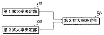
図2は本発明の一実施形態に係る画像に対する最適な拡大率を決定するデータ処理装置内の拡大率決定部のブロック図である。 FIG. 2 is a block diagram of an enlargement ratio determining unit in the data processing apparatus that determines an optimum enlargement ratio for an image according to an embodiment of the present invention.
図2に示すように、データ処理装置151は、撮影機のハードウェア的属性に基づいて第1拡大率を決定する第1拡大率決定部210、ボクセルサイズに基づいて第2拡大率を決定する第2拡大率決定部220、及び第1拡大率と第2拡大率に基づいて画像の最適拡大率を決定する第3拡大率決定部230を含んでなる。ここで、ハードウェア的属性は光源111の焦点サイズ、検出器114のピクセルサイズ及び検出器114の解像力のうち少なくとも一つを含むことができる。以下、説明の便宜上、ハードウェア的属性は焦点サイズ、ピクセルサイズ及び検出器114の解像力を全て意味すると仮定する。
As shown in FIG. 2, the
図3は本発明の一実施形態に係る第1拡大率決定部の動作を説明するための参考図である。 FIG. 3 is a reference diagram for explaining the operation of the first enlargement factor determination unit according to the embodiment of the present invention.
撮影機は被検体を拡大撮影することができる。この際の拡大率を横軸とし、撮影機が獲得すべき画像の空間周波数を縦軸とするとき、焦点サイズ、ピクセルサイズ、センサーの解像度それぞれと拡大率及び空間周波数の関係は図3のように図示できる。 The photographing machine can magnify the subject. When the horizontal axis represents the magnification ratio and the vertical axis represents the spatial frequency of the image to be acquired by the camera, the relationship between the focal size, pixel size, sensor resolution, magnification ratio, and spatial frequency is as shown in FIG. Can be illustrated.
焦点サイズ(f)、拡大率(M)及び空間周波数(u)は次の数式1で表される。

一方、ピクセルサイズ(d)、拡大率(M)及び空間周波数(u)は次の数式2で表される。
一方、検出器の解像力、すなわちセンサーの解像度(b)、拡大率(M)及び空間周波数(u)は次の数式3で表される。
第1拡大率決定部210は、図3に示した曲線及び直線を認知している。言い換えれば、第1拡大率決定部210はピクセルサイズ、センサーの解像度、焦点サイズそれぞれの空間周波数と拡大率の関係情報を予め記憶している。第1拡大率決定部210は各拡大率毎にピクセルサイズ、センサーの解像度、焦点サイズに対応する空間周波数のうち最小値を決定する。決定された最小値は図3に破線で表示された曲線MF上の値である。第1拡大決定部210は決定された最小値のうち、すなわち曲線MF上の空間周波数のうち最大値空間周波数における拡大率Mを第1拡大率として決定する。
The first enlargement
第2拡大率決定部220は、ボクセルサイズに基づいて次の数式4で第2拡大率(Pm)を決定する。
第3拡大率決定部230は、第1拡大率と第2拡大率との間の値を最適な第3拡大率として決定する。好ましくは、第3拡大率は第1拡大率と第2拡大率との平均値でありうる。また、第3拡大率決定部230はFOV、検出器114のサイズ及び種類などによって最適な第3拡大率を決定するが、参照データに基づいて最適な第3拡大率を決定することができる。前記参照データは、FOV、検出器114のサイズ及び検出器114の種類などに応じて実験によって既に獲得された最適な第3拡大率でありうる。
The third enlargement
拡大率制御器113は、第3拡大率決定部230によって決定された拡大率に応じて撮影機を制御する。具体的に、拡大率は(光源111と検出器114との距離)/(光源111と被検体との距離)である。これにより、拡大率制御器113は決定された拡大率となるように撮影機を移動させる。
The
図4は本発明の一実施形態に係る検出器が移動可能なX線断層撮影装置の断面図である。図4に示すように、回転体116の回転軸410を中心に検出器114が取り付けられている部材430は水平方向に移動可能である。これにより、拡大率制御器113は検出器114を左右に移動させ、決定された拡大率となるようにする。
FIG. 4 is a cross-sectional view of an X-ray tomography apparatus in which a detector according to an embodiment of the present invention can move. As shown in FIG. 4, the
図5は本発明の一実施形態に係る撮影機が移動可能なX線断層撮影装置の断面図である。図5に示すように、撮影機が取り付けられている部材は水平方向に移動可能である。これにより、拡大率制御器の制御に基づいて撮影機を左右に移動させ、決定された拡大率となるようにする。 FIG. 5 is a cross-sectional view of an X-ray tomography apparatus to which an imaging machine according to an embodiment of the present invention can move. As shown in FIG. 5, the member to which the camera is attached can move in the horizontal direction. Accordingly, the photographing machine is moved to the left and right based on the control of the enlargement ratio controller so that the determined enlargement ratio is obtained.
このように、FOV及びボクセルサイズに基づいて最適な拡大率を決定し、決定された拡大率で被検体を撮影するため、既存の画像に比べて解像度が増加し、信号雑音比(Signal to Noise Ratio)が増加し、エイリアシングアーチファクト(Aliasing artifact)が減少する効果がある。 In this way, the optimal magnification ratio is determined based on the FOV and the voxel size, and the subject is imaged at the determined magnification ratio. Therefore, the resolution is increased compared to the existing image, and the signal-to-noise ratio (Signal to Noise) is increased. Ratio is increased, and aliasing artifacts are reduced.
また、データ処理装置151の画像再構成部(図示せず)は、データ収集バッファ153から伝送された被検体透過情報(断層情報)、すなわちデジタルデータを画像再構成アルゴリズムによって再構成した3次元画像を獲得する。
In addition, an image reconstruction unit (not shown) of the
この際、前記画像再構成部は可変フィルターパノラマ逆透写方法(adaptive filtered panoramic back projection)を用いて3次元画像に再構成することができる。すなわち、獲得したそれぞれの画像を仮想回転軸を中心に逆透写し、仮想回転軸と検出器114との距離Rによるフィルター値を計算して適用する。ここで、前記仮想回転軸とは、光が検出される検出器114の受光面を基準にした回転軸を意味し、仮想回転軸と検出器114との距離Rは常に変化するので、フィルター値もそれぞれ異ならせて適用しなければならない。
At this time, the image reconstruction unit can reconstruct the image into a three-dimensional image using a variable filter panoramic back projection method. That is, each acquired image is reverse-transparented around the virtual rotation axis, and a filter value according to the distance R between the virtual rotation axis and the
図6及び図7は本発明の一実施形態に係る仮想回転軸を説明するための図である。図6及び図7に示すように、被検体中の関心領域に位置したイメージレイヤーに光を照射する光源111と、イメージレイヤーを透過した光を検出する検出器114との間に被検体を位置させる。
6 and 7 are views for explaining a virtual rotation axis according to an embodiment of the present invention. As shown in FIGS. 6 and 7, the subject is positioned between a
前記イメージレイヤーの時点にX線を照射して前記イメージレイヤーの時点部分の画像を獲得し始める。続いて、前記イメージレイヤーの次の部分を連続して撮影するために、光源111と検出器114を第1軌跡に沿って移動させるとともに、前記仮想回転軸を第1軌跡とは異なる第2軌跡に沿って移動させる。この際、前記光源111と前記検出器114は移動中にも連続して光を照射し、検出する。また、前記仮想回転軸と前記検出器114の受光面との距離Rは変化し続ける。
X-rays are irradiated at the time of the image layer to start acquiring an image of the time portion of the image layer. Subsequently, in order to continuously photograph the next portion of the image layer, the
次いで、前記イメージレイヤーの終点部分まで前記光源111と前記検出器114を駆動させて画像を獲得する。
Next, the
すなわち、本発明は、光源111と検出器114をパノラマ撮影法による軌跡とCT撮影法による遺跡とを併合した新しい軌跡で駆動させながら、画像を獲得することができる。こうして撮影軌跡を単純にし、撮影時間を短縮しながらも擦弦楽器の弓状の3次元画像を獲得することができるという効果がある。そして、この際のデータ処理装置151は可変フィルターパノラマ逆透写方法(adaptive filtered panoramic back projection)を用いて3次元画像に再構成する。
That is, according to the present invention, an image can be acquired while driving the
前記可変フィルターパノラマ逆透写方法は、獲得されたフレーム画像を光源111の焦点位置まで照射方向に合わせて3次元で満たしていき、全てのフレームを重畳で満たしていくことにより画像を再構成する一般逆透写方法と基本原理は同じである。
In the variable filter panorama reverse transmission method, the acquired frame image is filled in three dimensions in accordance with the irradiation direction up to the focal position of the
但し、撮影機(光源111及び検出器114)の運動と共に仮想回転軸が連続的に運動する場合には、回転体116の回転軸の位置による逆透写回転位置を合わせながら、ぼけ(blurring)及びアーチファクト(artifact)を除去するためのフィルターの設計の際に仮想回転軸と検出器114との距離Rが固定値ではなく可変するから、その距離によるそれぞれのフィルター値を計算して画像を補正する再構成方法を意味する。そして、仮想回転軸と検出器114との距離Rが固定値ではなく可変するにつれてフィルター値が変更される前記フィルターを可変フィルターとする。
However, when the virtual rotation axis continuously moves along with the movement of the photographing device (
図8は本発明の一実施形態に係る拡大率に基づいて画像を撮影する方法を説明する流れ図である。 FIG. 8 is a flowchart illustrating a method for capturing an image based on an enlargement ratio according to an embodiment of the present invention.
図8に示すように、ユーザーが操作部を介してFOV及びボクセルサイズを入力すると(S810−Y)、拡大率決定部はFOV及びボクセルサイズに基づいて拡大率を決定する(S820)。 As shown in FIG. 8, when the user inputs the FOV and the voxel size via the operation unit (S810-Y), the enlargement rate determination unit determines the enlargement rate based on the FOV and the voxel size (S820).
具体的に、第1拡大率決定部210は撮影機のハードウェア的属性(例えば、焦点サイズ、ピクセルサイズ、及びセンサーの解像力)を考慮して第1拡大率を決定する。第2拡大率決定部220はボクセルサイズに基づいて第2拡大率を決定する。その後、第3拡大率決定部230は第1拡大率及び第2拡大率に基づいて最終拡大率を決定する。
Specifically, the first enlargement
決定された拡大率は制御インターフェース152を介して拡大率制御器113へ伝送される。拡大率制御器113は撮影機が前記拡大率で被検体を撮影するように撮影機を移動させる(S830)。撮影機を移動させるにあたり、光源111が固定された状態で検出器114のみ水平方向に移動してもよく、光源111及び検出器114の両方ともが移動してもよい。
The determined enlargement ratio is transmitted to the
撮影機は決定された拡大率で被検体を複数回撮影して複数の画像を獲得する(S840)。すなわち、回転体116が被検体を中心に微小な角度間隔で回転すると、検出器114は各位置で被検体を透過した光源111の透過情報(断層画像情報)を検出してデータ収集部115に印加する。データ収集部115は光源111の透過情報(断層画像情報)に応じて発生する一連の電圧信号をデジタルデータに変換してデータ収集バッファ153へ伝達し、データ収集バッファ153は入力される断層画像に関するデジタルデータを順序通りにデータ処理装置151へ伝送する。データ処理装置151は伝送された被検体透過情報(断層情報)を画像再構成アルゴリズムによって再構成した3次元画像を獲得する。
The imaging apparatus captures a plurality of images by imaging the subject a plurality of times with the determined magnification (S840). That is, when the
上述した本発明の少なくとも一実施形態に係る高解像度パノラマ画像獲得方法をコンピュータで実行させるためのプログラムは、コンピュータで読み取ることが可能な記録媒体に記憶できる。ここで、コンピュータで読み取ることが可能な記録媒体はマグネチック記憶媒体(例えば、ROM、フロッピー(登録商標)ディスク、ハードディスクなど)、及び光学的読取媒体(例えば、CD−ROM、DVD(Digital Versatile Disc))などの記憶媒体を含む。 A program for causing a computer to execute the above-described high-resolution panoramic image acquisition method according to at least one embodiment of the present invention can be stored in a computer-readable recording medium. Here, computer-readable recording media include magnetic storage media (for example, ROM, floppy (registered trademark) disk, hard disk, etc.), and optical reading media (for example, CD-ROM, DVD (Digital Versatile Disc). )) And other storage media.
以上、本発明の好適な実施形態について図示及び説明したが、本発明は、上述した特定の実施形態に限定されず、請求の範囲で請求する本発明の要旨から逸脱することなく、当該発明の属する技術分野における通常の知識を有する者によって多様な変形実施が可能なのはもとより、それらの変形実施は本発明の技術的思想又は展望から個別的に理解されてはならない。 The preferred embodiments of the present invention have been illustrated and described above, but the present invention is not limited to the specific embodiments described above, and the present invention is not deviated from the gist of the present invention claimed in the claims. Various modifications may be made by those having ordinary knowledge in the technical field to which they belong, and such modifications should not be individually understood from the technical idea or perspective of the present invention.
デンタルCTを用いて患者の特定領域を撮影するとき、最適な拡大率で被検体を撮影するから、既存の画像に比べて解像度が増加し、信号雑音比(Signal to Noise Ratio)が増加し、エイリアシングアーチファクト(Aliasing artifact)が減少する効果がある。また、仮想回転軸が変更されるときに可変フィルターのフィルター値も適応的に変更することにより、より高解像度の画像を獲得する効果がある。 When imaging a specific area of a patient using dental CT, the subject is imaged at the optimal magnification, so the resolution increases compared to existing images, and the signal to noise ratio increases. This has the effect of reducing aliasing artifacts. Moreover, there is an effect of acquiring a higher resolution image by adaptively changing the filter value of the variable filter when the virtual rotation axis is changed.
Claims (14)
前記撮影機のハードウェア的属性及び入力されたボクセルサイズを用いて被検体に対する画像の拡大率を決定する拡大率決定部と、
前記決定された拡大率に対応するように前記撮影機を移動させる拡大率制御器とを含み、
前記拡大率決定部は、
前記撮影機のハードウェア的属性に基づいて第1拡大率を決定する第1拡大率決定部と、
前記ボクセルサイズに基づいて第2拡大率を決定する第2拡大率決定部と、
前記第1拡大率と前記第2拡大率との間の値を前記被検体に対する画像の拡大率として決定する第3拡大率決定部とを含んでなる、X線断層撮影装置。 An imaging device for irradiating the subject with light and detecting the light transmitted through the subject;
A magnification determining section for determining a magnification of an image for a subject using the hardware attributes and input Bokuserusai's of the motion picture camera,
An enlargement ratio controller that moves the camera to correspond to the determined enlargement ratio;
The enlargement ratio determining unit
A first enlargement factor determining unit for determining a first enlargement factor based on hardware attributes of the photographing device;
A second enlargement factor determining unit for determining a second enlargement factor based on the voxel size;
An X-ray tomography apparatus comprising: a third magnification determining unit that determines a value between the first magnification and the second magnification as an image magnification for the subject.
前記光を前記被検体に照射する光源と、
前記被検体を透過した前記光を検出する検出器とを含んでなることを特徴とする、請求項1に記載のX線断層撮影装置。 The camera is
A light source for irradiating the subject with the light;
The X-ray tomography apparatus according to claim 1, further comprising a detector that detects the light transmitted through the subject.
前記可変フィルターパノラマ逆透写方法は、前記撮影機によって獲得された画像を前記検出器の受光面を基準にした回転軸としての仮想回転軸を中心に逆透写し、前記仮想回転軸と前記検出器との距離によって異なるフィルター値を適用して前記画像を補正して再構成することを特徴とする、請求項3に記載のX線断層撮影装置。 An image reconstruction unit that reconstructs an image of the subject into a three-dimensional image using a variable filter panoramic reverse transmission method;
It said variable filter panorama reverse tracings method, the mainly virtual axis of rotation of the images acquired by the imaging unit as a rotational axis relative to the receiving surface before dangerous out unit opposite Sukiutsushi, and the virtual rotation axis The X-ray tomography apparatus according to claim 3 , wherein the image is corrected and reconstructed by applying different filter values depending on a distance from the detector.
前記決定された拡大率に対応するように前記撮影機を移動させる段階と、
前記移動させた撮影機を回転させながら前記被検体に対する画像を獲得する段階とを含み、
前記拡大率を決定する段階は、
前記撮影機のハードウェア的属性に基づいて第1拡大率を決定する段階と、
前記ボクセルサイズに基づいて第2拡大率を決定する段階と、
前記第1拡大率と前記第2拡大率との間の値を前記被検体に対する画像の拡大率として決定する段階とを含んでなることを特徴とする、断層画像獲得方法。 A step of light is irradiated to a subject to determine the magnification of the image with respect to hardware attributes and input the subject using Bokuserusai's was a motion picture camera which detects the light transmitted through the object,
Moving the camera to correspond to the determined magnification factor;
Obtaining an image of the subject while rotating the moved imaging device,
The step of determining the enlargement ratio includes:
Determining a first magnification based on hardware attributes of the camera;
Determining a second magnification based on the voxel size;
Determining a value between the first magnification and the second magnification as an image magnification for the subject.
前記可変フィルターパノラマ逆透写方法は、前記撮影機によって獲得された画像を前記検出器の受光面を基準にした回転軸としての仮想回転軸を中心に逆透写し、前記仮想回転軸と前記検出器との距離によって異なるフィルター値を適用して前記画像を補正して再構成することを特徴とする、請求項10に記載の断層画像獲得方法。 After obtaining the image, further comprising reconstructing an image of the subject into a three-dimensional image using a variable filter panoramic reverse transmission method;
It said variable filter panorama reverse tracings method, the mainly virtual axis of rotation of the images acquired by the imaging unit as a rotational axis relative to the receiving surface before dangerous out unit opposite Sukiutsushi, and the virtual rotation axis The tomographic image acquisition method according to claim 10 , wherein the image is corrected and reconstructed by applying different filter values depending on a distance from the detector.
Applications Claiming Priority (3)
| Application Number | Priority Date | Filing Date | Title |
|---|---|---|---|
| KR1020100003220A KR101190801B1 (en) | 2010-01-13 | 2010-01-13 | X-ray computed tomography apparatus and the method thereof |
| KR10-2010-0003220 | 2010-01-13 | ||
| PCT/KR2011/000267 WO2011087306A2 (en) | 2010-01-13 | 2011-01-13 | X-ray computed tomographic imaging apparatus and method for same |
Publications (3)
| Publication Number | Publication Date |
|---|---|
| JP2013517045A JP2013517045A (en) | 2013-05-16 |
| JP2013517045A5 JP2013517045A5 (en) | 2014-02-27 |
| JP5784040B2 true JP5784040B2 (en) | 2015-09-24 |
Family
ID=44304828
Family Applications (1)
| Application Number | Title | Priority Date | Filing Date |
|---|---|---|---|
| JP2012548890A Active JP5784040B2 (en) | 2010-01-13 | 2011-01-13 | X-ray tomography apparatus and method |
Country Status (5)
| Country | Link |
|---|---|
| US (1) | US9532755B2 (en) |
| EP (1) | EP2508133B1 (en) |
| JP (1) | JP5784040B2 (en) |
| KR (1) | KR101190801B1 (en) |
| WO (1) | WO2011087306A2 (en) |
Families Citing this family (10)
| Publication number | Priority date | Publication date | Assignee | Title |
|---|---|---|---|---|
| KR101501516B1 (en) | 2012-01-09 | 2015-03-11 | 삼성메디슨 주식회사 | The method and apparatus for measuring a captured object using brightness information and magnified image of a captured image |
| KR101401927B1 (en) * | 2012-06-29 | 2014-05-30 | 주식회사 덴티움 | X-ray photographing apparatus combining panorama and ct for dental clinic |
| KR102060659B1 (en) | 2013-03-20 | 2019-12-30 | 삼성전자주식회사 | Projection and backprojection methods for image processing and image processing apparatus thereof |
| EP3037039B1 (en) | 2013-08-20 | 2018-07-18 | Vatech Co. Ltd. | X-ray imaging device |
| KR102285553B1 (en) * | 2014-07-29 | 2021-08-05 | 주식회사 바텍 | Apparatus for 2 Dimensional Tomography and Method Thereof |
| JP6666283B2 (en) | 2017-02-23 | 2020-03-13 | 株式会社モリタ製作所 | X-ray tomography apparatus and X-ray tomography method |
| JP6837400B2 (en) * | 2017-08-23 | 2021-03-03 | 株式会社モリタ製作所 | X-ray imaging device and X-ray imaging method |
| KR102043357B1 (en) * | 2017-10-18 | 2019-11-12 | 오스템임플란트 주식회사 | A method for changing a scale of an image and an apparatus for the same |
| JP6837452B2 (en) * | 2018-04-27 | 2021-03-03 | 株式会社モリタ製作所 | Control method of X-ray CT imaging device and X-ray CT imaging device |
| EP3649957B1 (en) * | 2018-11-07 | 2023-07-19 | DENTSPLY SIRONA Inc. | Device and method for editing a panoramic radiography image |
Family Cites Families (17)
| Publication number | Priority date | Publication date | Assignee | Title |
|---|---|---|---|---|
| WO1993019672A1 (en) | 1992-04-01 | 1993-10-14 | Sony Corporation | Radiation diagnostic apparatus |
| JP2003116837A (en) | 1992-04-01 | 2003-04-22 | Sony Corp | Radiation diagnostic equipment |
| KR200261705Y1 (en) | 2001-09-04 | 2002-01-24 | 주한식 | Digital X-ray photographing device |
| JP2003175031A (en) * | 2001-10-02 | 2003-06-24 | Morita Mfg Co Ltd | Digital x-ray panoramic imaging apparatus |
| JP2003230555A (en) * | 2002-02-07 | 2003-08-19 | Toshiba Corp | X-ray fluoroscopic imaging diagnostic equipment |
| US6692441B1 (en) * | 2002-11-12 | 2004-02-17 | Koninklijke Philips Electronics N.V. | System for identifying a volume of interest in a volume rendered ultrasound image |
| JP2004208773A (en) | 2002-12-27 | 2004-07-29 | Konica Minolta Holdings Inc | Radiation image forming system |
| US7570730B2 (en) * | 2004-03-17 | 2009-08-04 | Koninklijke Philips Electronics N.V. | Multiple focus acquisition |
| KR100687846B1 (en) * | 2005-01-21 | 2007-02-27 | 경희대학교 산학협력단 | Local high resolution x-ray tomography image reconstruction method and local high resolution x-ray tomography image reconstruction apparatus |
| JP4632891B2 (en) | 2005-07-22 | 2011-02-16 | 株式会社モリタ製作所 | X-ray CT imaging apparatus and X-ray CT imaging method |
| US8077937B2 (en) * | 2005-11-18 | 2011-12-13 | Cornell University | Reproducible objective quantification method to segment white matter structures |
| JP2007170921A (en) | 2005-12-20 | 2007-07-05 | Rigaku Corp | X-ray ct device |
| US7394889B2 (en) * | 2006-05-18 | 2008-07-01 | Varian Medical Systems Technologies, Inc. | Contrast-enhanced cone beam X-ray imaging, evaluation, monitoring and treatment delivery |
| JP4909730B2 (en) * | 2006-12-15 | 2012-04-04 | 株式会社東芝 | X-ray diagnostic imaging apparatus and movement control method |
| US7548604B2 (en) * | 2007-01-04 | 2009-06-16 | General Electric Company | Method and apparatus for reduction of metal artifacts in CT imaging |
| EP2210559B1 (en) * | 2007-11-16 | 2016-09-07 | J. Morita Manufacturing Corporation | X-ray ct imaging device |
| KR20090130719A (en) | 2008-06-16 | 2009-12-24 | 주식회사바텍 | Tomography image acquisition method |
-
2010
- 2010-01-13 KR KR1020100003220A patent/KR101190801B1/en active IP Right Grant
-
2011
- 2011-01-13 EP EP11733093.6A patent/EP2508133B1/en active Active
- 2011-01-13 US US13/521,926 patent/US9532755B2/en active Active
- 2011-01-13 JP JP2012548890A patent/JP5784040B2/en active Active
- 2011-01-13 WO PCT/KR2011/000267 patent/WO2011087306A2/en active Application Filing
Also Published As
| Publication number | Publication date |
|---|---|
| WO2011087306A9 (en) | 2011-10-20 |
| WO2011087306A2 (en) | 2011-07-21 |
| KR101190801B1 (en) | 2012-10-12 |
| KR20110083153A (en) | 2011-07-20 |
| US9532755B2 (en) | 2017-01-03 |
| JP2013517045A (en) | 2013-05-16 |
| US20120307960A1 (en) | 2012-12-06 |
| WO2011087306A3 (en) | 2011-12-08 |
| EP2508133A2 (en) | 2012-10-10 |
| EP2508133B1 (en) | 2019-10-30 |
| EP2508133A4 (en) | 2013-07-31 |
Similar Documents
| Publication | Publication Date | Title |
|---|---|---|
| JP5784040B2 (en) | X-ray tomography apparatus and method | |
| EP2609864B1 (en) | A single sensor multi-functional dental extra-oral x-ray imaging system and method | |
| JP4054402B2 (en) | X-ray tomography equipment | |
| JP5528518B2 (en) | Radiation image generating apparatus and method | |
| EP2419018B1 (en) | A single sensor multi-functional dental extra oral x-ray imaging system and method | |
| JP4537129B2 (en) | System for scanning objects in tomosynthesis applications | |
| JP5878119B2 (en) | X-ray CT apparatus and control method thereof | |
| JP3548339B2 (en) | X-ray equipment | |
| KR20060120511A (en) | Reconstruction method of X-ray CT image and X-ray CT system | |
| KR102097564B1 (en) | Method and Apparatus for Forming an X-ray Image | |
| JP4852451B2 (en) | Synchronous imaging device for periodic motion and synchronous imaging method for periodic motion | |
| JP3540916B2 (en) | 3D X-ray CT system | |
| KR20200095740A (en) | Medical imaging apparatus and controlling method for the same | |
| EP2793702A1 (en) | Dental imaging with photon-counting detector | |
| KR101873109B1 (en) | Two-dimensional x-ray detector, cone-beam ct apparatus and method using region-of-interest | |
| JP2001330568A5 (en) | ||
| KR101001680B1 (en) | 3D image acquisition device | |
| JP6853376B2 (en) | How to reconstruct a 2D image from multiple X-ray images | |
| JP2007260187A (en) | Radiation tomographic apparatus | |
| JPWO2006028085A1 (en) | X-ray CT apparatus, image processing program, and image processing method | |
| KR101531370B1 (en) | X-ray Imaging Device And Imaging Method Thereof | |
| KR102203530B1 (en) | Method and Apparatus for generating x-ray image, computer-readable recording medium | |
| JPH09234192A (en) | X-ray photography device | |
| JP2014068985A (en) | Radiographic apparatus |
Legal Events
| Date | Code | Title | Description |
|---|---|---|---|
| A521 | Request for written amendment filed |
Free format text: JAPANESE INTERMEDIATE CODE: A523 Effective date: 20140110 |
|
| A621 | Written request for application examination |
Free format text: JAPANESE INTERMEDIATE CODE: A621 Effective date: 20140110 |
|
| A977 | Report on retrieval |
Free format text: JAPANESE INTERMEDIATE CODE: A971007 Effective date: 20140919 |
|
| A131 | Notification of reasons for refusal |
Free format text: JAPANESE INTERMEDIATE CODE: A131 Effective date: 20141014 |
|
| A521 | Request for written amendment filed |
Free format text: JAPANESE INTERMEDIATE CODE: A523 Effective date: 20150106 |
|
| TRDD | Decision of grant or rejection written | ||
| A01 | Written decision to grant a patent or to grant a registration (utility model) |
Free format text: JAPANESE INTERMEDIATE CODE: A01 Effective date: 20150623 |
|
| A61 | First payment of annual fees (during grant procedure) |
Free format text: JAPANESE INTERMEDIATE CODE: A61 Effective date: 20150721 |
|
| R150 | Certificate of patent or registration of utility model |
Ref document number: 5784040 Country of ref document: JP Free format text: JAPANESE INTERMEDIATE CODE: R150 |
|
| R250 | Receipt of annual fees |
Free format text: JAPANESE INTERMEDIATE CODE: R250 |
|
| R250 | Receipt of annual fees |
Free format text: JAPANESE INTERMEDIATE CODE: R250 |
|
| R250 | Receipt of annual fees |
Free format text: JAPANESE INTERMEDIATE CODE: R250 |
|
| R250 | Receipt of annual fees |
Free format text: JAPANESE INTERMEDIATE CODE: R250 |
|
| R250 | Receipt of annual fees |
Free format text: JAPANESE INTERMEDIATE CODE: R250 |
|
| R250 | Receipt of annual fees |
Free format text: JAPANESE INTERMEDIATE CODE: R250 |
|
| R250 | Receipt of annual fees |
Free format text: JAPANESE INTERMEDIATE CODE: R250 |