JP5779004B2 - connector - Google Patents
connector Download PDFInfo
- Publication number
- JP5779004B2 JP5779004B2 JP2011132119A JP2011132119A JP5779004B2 JP 5779004 B2 JP5779004 B2 JP 5779004B2 JP 2011132119 A JP2011132119 A JP 2011132119A JP 2011132119 A JP2011132119 A JP 2011132119A JP 5779004 B2 JP5779004 B2 JP 5779004B2
- Authority
- JP
- Japan
- Prior art keywords
- connector
- base spring
- mating
- pitch direction
- holding member
- Prior art date
- Legal status (The legal status is an assumption and is not a legal conclusion. Google has not performed a legal analysis and makes no representation as to the accuracy of the status listed.)
- Active
Links
Images


Description
本発明は、相手側コネクタと嵌合するコネクタであって低背化を求められるコネクタに関する。 The present invention relates to a connector that is fitted to a mating connector and is required to have a low profile.
特許文献1は、同軸ケーブルを接続されたプラグコネクタ(コネクタ装置)と、基板に搭載固定されるレセプタクルコネクタ(基板側コネクタ装置)とを開示している。プラグコネクタの導電性カバーのピッチ方向の両端近傍には上側に突出した係合突起が設けられている。一方、レセプタクルコネクタの導電性シェルの上部のピッチ方向の両端近傍には、その導電性シェルの上部を上下方向において貫通する係合孔が形成されている。プラグコネクタをレセプタクルコネクタに嵌合すると、係合突起が係合孔にそれぞれ係合し、それによって導電性カバーと導電性シェルとが接続される。 Patent Document 1 discloses a plug connector (connector device) to which a coaxial cable is connected and a receptacle connector (substrate-side connector device) mounted and fixed on a substrate. Engaging protrusions protruding upward are provided in the vicinity of both ends in the pitch direction of the conductive cover of the plug connector. On the other hand, in the vicinity of both ends in the pitch direction of the upper portion of the conductive shell of the receptacle connector, engagement holes are formed that penetrate the upper portion of the conductive shell in the vertical direction. When the plug connector is fitted to the receptacle connector, the engagement protrusions are respectively engaged with the engagement holes, thereby connecting the conductive cover and the conductive shell.
プラグコネクタとレセプタクルコネクタとの嵌合時にクリック感をユーザに伝えると共に嵌合状態を確実に保持するためには、係合突起の係合孔への係合前後における係合突起の変位量を大きくしなければならない。 In order to convey a click feeling to the user when the plug connector and the receptacle connector are fitted together and to securely hold the fitting state, the displacement amount of the engaging protrusion is increased before and after the engaging protrusion is engaged with the engaging hole. Must.
しかしながら、特許文献1のプラグコネクタ及びレセプタクルコネクタにおいて係合突起の変位量を大きくするためには、プラグコネクタやレセプタクルコネクタの高さ方向又は厚み方向のサイズを大きくしなければならず、低背化の要求を満たせないといった問題がある。 However, in order to increase the displacement amount of the engaging protrusion in the plug connector and the receptacle connector of Patent Document 1, the size of the plug connector and the receptacle connector in the height direction or the thickness direction must be increased, and the height is reduced. There is a problem that it cannot meet the requirements of
そこで、本発明は、相手側コネクタとの嵌合時に十分なクリック感をユーザに伝えることができると共に嵌合状態を確実に保持することができるコネクタであって、低背化の要求にも対応可能な構造を有するコネクタを提供することを目的とする。 Therefore, the present invention is a connector that can transmit a sufficient click feeling to the user when mating with the mating connector and can securely hold the mating state, and can respond to the demand for low profile. An object is to provide a connector having a possible structure.
本発明は、第1のコネクタとして、
相手側係合部の形成された相手側シェルを有する相手側コネクタと嵌合するコネクタであって、
複数のコンタクトと、前記コンタクトをピッチ方向に列設保持する保持部材と、前記保持部材に一端を保持されたベースバネ部とを備えており、
前記ベースバネ部は、前記ピッチ方向と直交する前方向に延びており、且つ、前記ピッチ方向に撓み可能であり、
前記ベースバネ部には、前記相手側係合部と係合し、弾性変形可能な係合部が設けられており、
前記前方向の逆方向である後方向に沿って前記相手側コネクタを前記コネクタに対して嵌合させる過程において、前記ベースバネ部が初期状態から前記ピッチ方向に撓んだ後、前記ベースバネ部が前記初期状態に向かって戻ろうとしつつ前記係合部が前記相手側係合部に係合するように構成されている、コネクタを提供する。
The present invention provides the first connector as
A connector that mates with a mating connector having a mating shell formed with a mating engagement portion,
A plurality of contacts; a holding member that holds the contacts in a pitch direction; and a base spring portion that has one end held by the holding member.
The base spring portion extends in the front direction orthogonal to the pitch direction, and can be bent in the pitch direction.
The base spring portion is provided with an engagement portion that engages with the mating engagement portion and is elastically deformable,
In the process of fitting the mating connector to the connector along the rear direction which is the reverse direction of the front direction, after the base spring portion is bent in the pitch direction from an initial state, the base spring portion is Provided is a connector configured so that the engaging portion engages with the mating engaging portion while returning toward an initial state.
また、本発明は、第2のコネクタとして、第1のコネクタであって、
前記ベースバネ部は、板状の形状を有しており、前記ピッチ方向と直交している
コネクタを提供する。
Moreover, this invention is a 1st connector as a 2nd connector,
The base spring portion has a plate shape and provides a connector orthogonal to the pitch direction.
また、本発明は、第3のコネクタとして、第1又は第2のコネクタであって、
前記係合部は、前記ベースバネ部から前記ピッチ方向に隆起するように曲げ形成されたバネ係合部である
コネクタを提供する。
Moreover, this invention is a 1st or 2nd connector as a 3rd connector,
The engagement portion provides a connector that is a spring engagement portion that is bent so as to protrude from the base spring portion in the pitch direction.
また、本発明は、第4のコネクタとして、第3のコネクタであって、
前記バネ係合部の前端及び後端は、前記ベースバネ部と連続している
コネクタを提供する。
Moreover, this invention is a 3rd connector as a 4th connector,
A front end and a rear end of the spring engaging portion provide a connector that is continuous with the base spring portion.
また、本発明は、第5のコネクタとして、第3又は第4のコネクタであって、
前記バネ係合部には、前記ピッチ方向に突出した接点であって前記相手側コネクタが前記コネクタに嵌合する際に前記相手側シェルに接続する接点が設けられている
コネクタを提供する。
Moreover, this invention is a 3rd or 4th connector as a 5th connector,
The spring engagement portion is provided with a connector provided with a contact protruding in the pitch direction and connected to the mating shell when the mating connector is fitted to the connector.
また、本発明は、第6のコネクタとして、第1乃至第5のいずれかのコネクタであって、
基板に固定されるホールドダウンと、前記保持部材に組み込まれたシェルとを更に備えている
コネクタを提供する。
Moreover, this invention is a connector in any one of 1st thru | or 5 as a 6th connector,
There is provided a connector further comprising a holddown fixed to a substrate and a shell incorporated in the holding member.
また、本発明は、第7のコネクタとして、第6のコネクタであって、
前記ベースバネ部の前端から後方に向けて折り返された撓み限界規定部を更に備えており、
前記撓み限界規定部は、前記ピッチ方向において前記ベースバネ部と前記ホールドダウンとの間に位置しており、前記前方向及び前記後方向において前記ホールドダウンと少なくとも部分的に重複している
コネクタを提供する。
Moreover, this invention is a 6th connector as a 7th connector,
Further comprising a deflection limit defining portion folded back from the front end of the base spring portion;
The deflection limit defining portion is located between the base spring portion and the holddown in the pitch direction, and provides a connector that at least partially overlaps the holddown in the front direction and the rear direction. To do.
また、本発明は、第8のコネクタとして、第7のコネクタであって、
前記撓み限界規定部の前端及び前記ベースバネ部の前端並びに前記ホールドダウンの前端は、前記保持部材の前端よりも前方に位置している
コネクタを提供する。
Moreover, this invention is a 7th connector as an 8th connector,
The front end of the deflection limit defining portion, the front end of the base spring portion, and the front end of the hold-down provide a connector positioned forward of the front end of the holding member.
また、本発明は、第9のコネクタとして、第7又は第8のコネクタであって、
前記撓み限界規定部の後端は、前記保持部材に保持されている
コネクタを提供する。
Moreover, this invention is a 7th or 8th connector as a 9th connector,
A rear end of the deflection limit defining portion provides a connector held by the holding member.
また、本発明は、第10のコネクタとして、第7乃至第9のいずれかのコネクタであって、
前記ピッチ方向と直交し且つ前記後方向と直交する上下方向において、
前記撓み限界規定部の前端は前記ベースバネ部の幅と同一幅の広部を有し、前記撓み限界規定部の前記後方向に向かって延びる部分は前記広部よりも幅の狭い狭部を有する
コネクタを提供する。
Moreover, this invention is a connector in any one of 7th thru | or 9th as a 10th connector,
In the vertical direction perpendicular to the pitch direction and perpendicular to the rear direction,
The front end of the deflection limit defining portion has a wide portion having the same width as the width of the base spring portion, and the portion extending toward the rear direction of the deflection limit defining portion has a narrow portion narrower than the wide portion. Provide a connector.
また、本発明は、第11のコネクタとして、第7乃至第9のいずれかのコネクタであって、
前記保持部材は前記ピッチ方向における端部に前記前方向に突出する突出部を有しており、
前記撓み限界規定部の後端が前記突出部に保持されている
コネクタを提供する。
Further, the present invention is any one of the seventh to ninth connectors as the eleventh connector,
The holding member has a protruding portion protruding in the front direction at an end in the pitch direction,
Provided is a connector in which a rear end of the deflection limit defining portion is held by the protruding portion.
また、本発明は、第12のコネクタとして、第6乃至第11のいずれかのコネクタであって、
前記ベースバネ部は、前記シェルと一体形成されている
コネクタを提供する。
Moreover, this invention is a connector in any one of 6th thru | or 11th as a 12th connector,
The base spring portion provides a connector formed integrally with the shell.
また、本発明は、第13のコネクタとして、第6乃至第12のいずれかのコネクタであって、
前記シェルには、下板部と複数のグランドタブとが設けられており、
前記下板部は、前記相手側コネクタが前記コネクタに嵌合する際に前記相手側シェルと接続するものであり、且つ、前記ピッチ方向に長手を有する板状の形状を有するものであり、
前記グランドタブは、前記コネクタを前記基板に搭載した際に前記基板に接続されるものであり、且つ、前記ピッチ方向において互いに離間した状態で前記下板部から前方に突出するように配置されている
コネクタを提供する。
Further, the present invention is any of the sixth to twelfth connectors as the thirteenth connector,
The shell is provided with a lower plate portion and a plurality of ground tabs,
The lower plate portion is connected to the mating shell when the mating connector is fitted to the connector, and has a plate-like shape having a length in the pitch direction,
The ground tab is connected to the board when the connector is mounted on the board, and is arranged to protrude forward from the lower plate portion in a state of being separated from each other in the pitch direction. Provide a connector.
また、本発明は、第14のコネクタとして、第13のコネクタであって、
前記保持部材は、前記相手側コネクタの一部が挿入される挿入口を有しており、
前記下板部は、前記挿入口内において露出している
コネクタを提供する。
Moreover, this invention is a 13th connector as a 14th connector,
The holding member has an insertion port into which a part of the mating connector is inserted,
The lower plate portion provides a connector exposed in the insertion port.
本発明によれば、相手側コネクタの相手側係合部と係合させる係合部を上下方向ではなくピッチ方向に撓み可能なベースバネ部に設けたことから、低背化の要求を満たしつつ、十分なクリック感の創出や嵌合状態の確実な維持を実現することができる。 According to the present invention, since the engagement portion to be engaged with the mating engagement portion of the mating connector is provided in the base spring portion that can bend in the pitch direction instead of the vertical direction, while satisfying the demand for low profile, Creation of sufficient click feeling and reliable maintenance of the fitted state can be realized.
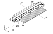
図1乃至図4に示されるように、本発明の実施の形態によるコネクタ組立体10は、コネクタ(レセプタクルコネクタ)100と、コネクタ100と嵌合可能な相手側コネクタ(プラグコネクタ)200とを備えている。コネクタ100は基板(図示せず)に搭載されるものであり、相手側コネクタ200は複数のケーブル50を取り付けられるものである。
As shown in FIGS. 1 to 4, the
図5乃至図7に示されるように、相手側コネクタ200は、金属からなる複数の相手側コンタクト210と、絶縁体からなる相手側保持部材220と、金属からなるカバーシェル(相手側シェル)230と、金属からなるベースシェル(相手側シェル)240と、金属からなるプルバー260とを備えている。本実施の形態による相手側コンタクト210とベースシェル240とは、インサート成型により、相手側保持部材220のモールド時に相手側保持部材220に組み込まれている。
As shown in FIGS. 5 to 7, the
相手側保持部材220は、−X方向に張り出した嵌合部222と、ピッチ方向(Y方向)の両端に設けられた支持部224とを有している。嵌合部222は、板状の形状を有しており、ピッチ方向(Y方向)に長手を有する細長い板状の形状を有している。図7に良く示されるように、嵌合部222の上面には、相手側コンタクト210が少なくとも部分的に露出している。また、嵌合部222の下面には、ベースシェル240が少なくとも部分的に露出している。
The
カバーシェル230は、相手側コンタクト210に対してケーブル50の導線を接続した後に、相手側保持部材220の上面をカバーするように取り付けられる。このカバーシェル230のピッチ方向(Y方向)の両端近傍にはピッチ方向(Y方向)内側に凹んだ係合孔(相手側係合部)252が形成されている。また、係合孔252のピッチ方向内側には相手側接点254が設けられている。
The
図5及び図6に示されるように、プルバー260は、ピッチ方向(Y方向)に長い角ばったC字状の形状を有している。プルバー260の両端には、支持部224に回転自在に支持される被支持部262が設けられている。被支持部262は、ピッチ方向(Y方向)の内側に向かって延びており、支持部224内に受容されている。プルバー260には、後述するようにコネクタ100の一部に係止する相手側係止部264が設けられている。本実施の形態による相手側係止部264は2箇所設けられている。
As shown in FIGS. 5 and 6, the
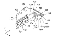
図8乃至図13に示されるように、コネクタ100は、金属からなる複数のコンタクト110と、絶縁体からなる保持部材120と、金属からなるシェル130とを備えている。本実施の形態によるシェル130は、インサート成型により、保持部材120のモールド時に保持部材120に組み込まれている。
8 to 13, the
図8,図10及び図11に示されるように、保持部材120は、ピッチ方向(Y方向)に長手を有する細長い板状の形状を有している。この保持部材120には、図8,図9及び図13に示されるように、前端120fから後方向(−X方向)に向かって凹んだ挿入口122が形成されている。この挿入口122は、図4,図7及び図13から理解されるように、相手側コネクタ200の嵌合部222を受容するための部位である。
As shown in FIGS. 8, 10, and 11, the holding
図8乃至図13から理解されるように、保持部材120の後端120bには、後方向(−X方向)に突出した係止部124が設けられている。係止部124は、ピッチ方向(Y方向)において互いに離間した状態で2箇所設けられている。具体的には、係止部124は、ピッチ方向(Y方向)に所定の幅を有しており、保持部材120の後端120bの上部から後方向(−X方向)に張り出している。図2から理解されるように、コネクタ100と相手側コネクタ200とを嵌合した状態でプルバー260を後方向(−X方向)に倒すように回動させると、プルバー260の相手側係止部264が係止部124の下側にもぐり込み、それによってコネクタ100と相手側コネクタ200との嵌合状態の維持が図られる。即ち、係止部124は、相手側係止部264と共に、コネクタ100と相手側コネクタ200との嵌合状態を維持するためのものである。
As can be understood from FIGS. 8 to 13, the holding
図13に示されるように、コンタクト110は、保持部材120の後端120bを通して保持部材120に圧入されている。それにより、コンタクト110の一部が挿入口122内に露出した状態で、コンタクト110は保持部材120に保持されている。図10及び図11に示されるように、コンタクト110は、ピッチ方向(Y方向)に並ぶように配置されている。
As shown in FIG. 13, the
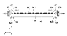
図14乃至図18に示されるように、シェル130は、上板部132と、下板部134と、それらをピッチ方向(Y方向)の両端近傍において連結する連結部136と、上板部132のピッチ方向(Y方向)の両端近傍から後方向(−X方向)に張り出した補強部138とを有している。上板部132及び下板部134は、いずれもピッチ方向(Y方向)に長手を有する細長い板状の形状を有している。前後方向(X方向)におけるサイズ及びピッチ方向(Y方向)のサイズに関し、下板部134は上板部132よりも小さい。連結部136は、2箇所設けられており、いずれも上板部132と下板部134とを前側で連結している。補強部138は、2箇所設けられており、いずれもピッチ方向(Y方向)において連結部136よりも外側に位置している。
As shown in FIGS. 14 to 18, the
上述したように、シェル130は、インサート成型により保持部材120に組み込まれている。その結果、図13に示されるように、下板部134は、挿入口122内に露出している。上述したように、挿入口122内にはコンタクト110の一部も露出している。従って、相手側コネクタ200の嵌合部222を挿入口122に挿入すると、コンタクト110と相手側コンタクト210との接続を図ることができると共にシェル130の下板部134と相手側コネクタ200のベースシェル(相手側シェル)240との接続を図ることができる。
As described above, the
また、図8,図9,図12,図14及び図18から理解されるように、連結部136及び補強部138は、保持部材120内に埋設されている。連結部136は、挿入口122のピッチ方向(Y方向)外側に位置している。補強部138は、係止部124内に位置しており、係止部124を強度補強している。そのため、係止部124と相手側係止部264による嵌合状態の維持を確実なものとすることができる。
Further, as understood from FIGS. 8, 9, 12, 14, and 18, the connecting
図14乃至図18に示されるように、本実施の形態によるシェル130には、ホールドダウン140と複数のグランドタブ142が形成されている。
As shown in FIGS. 14 to 18, a
ホールドダウン140は、コネクタ100を基板(図示せず)に搭載した際にその基板に固定される部位であり、上板部132のピッチ方向(Y方向)の両端から下方向(−Z方向)に向けて延びている。ホールドダウン140は、前方向(+X方向)と直交する面内(YZ平面内)においてL字状又は角ばったJ字状の断面形状を有している。図12に示されるように、本実施の形態によるホールドダウン140の前端140fは、保持部材120の前端120fよりも前方(+X側)に位置している。ホールドダウン140の後端140bは、保持部材120の前端120fよりも後端120bに近い位置に位置している。
The hold-down 140 is a part that is fixed to the board when the
グランドタブ142は、コネクタ100を基板(図示せず)に搭載した際にその基板上のグランドパターン(図示せず)に接続される部位であり、図13に示されるように、下板部134から前方に突出している。具体的には、グランドタブ142は、ピッチ方向(Y方向)と直交する面内(XZ平面内)においてクランク状の断面を有しており、従って、下板部134と基板上のグランドパターン(図示せず)とを接続することができる。また、これらグランドタブ142は、図8及び図14に示されるように、ピッチ方向(Y方向)において互いに離間して形成されている。これらグランドタブ142により、下板部134と相手側コネクタ200のベースシェル(相手側シェル)240とが接続された際に、ベースシェル240から基板上のグランドパターン(図示せず)までの電気的経路を短くすることができる。即ち、本実施の形態によるコネクタ組立体10においては、グランドの強化が図られている。
The
図8,図9,図12及び図13に示されるように、本実施の形態によるシェル130には、ベースバネ部150と、撓み限界規定部156とが更に設けられている。図15及び図18から理解されるように、本実施の形態によるベースバネ部150は、下板部134のピッチ方向(Y方向)の両端から上方(+Z側)に立ち上がり且つ前方(+X側)に延びる部位で構成されている。ベースバネ部150は、板状の形状を有しており、ピッチ方向(Y方向)と直交する面内(XZ平面内)において前方向(+X方向)に延びている。図9及び図12に示されるように、ベースバネ部150の後端150bは、保持部材120に保持されている。即ち、ベースバネ部150は、保持部材120から前方向(+X方向)に突出するように延びており、ピッチ方向(Y方向)に撓み可能となっている。
As shown in FIGS. 8, 9, 12, and 13, the
図13に示されるように、ベースバネ部150には、前後方向(X方向)に沿って延びる2つのスリット150sが形成されている。2つのスリット150sは、上下方向(Z方向)において離れて位置している。図9及び図13から理解されるように、スリット150sの間には、ピッチ方向(Y方向)の内側に隆起するように曲げ形成されてなるバネ係合部(係合部)152が設けられている。即ち、バネ係合部152は、上下方向(Z方向)においてスリット150sに挟まれているため、弾性変形可能となっている。また、本実施の形態においては、バネ係合部152の前端152f及び後端152bは、ベースバネ部150と連続している。即ち、本実施の形態によるバネ係合部152は両持ち構造のバネとなっている。バネ係合部152にはピッチ方向内側に更に突出した接点154が設けられている。
As shown in FIG. 13, the
図2,図5及び図9から理解されるように、コネクタ100と相手側コネクタ200との嵌合状態において、バネ係合部152は相手側コネクタ200の係合孔252に係合し、接点154は相手側接点254に接触する。詳しくは、後方向(−X方向)に沿って相手側コネクタ200をコネクタ100に対して嵌合させる際、バネ係合部152が係合孔252の周囲に乗り上げることにより、ベースバネ部150が初期状態からピッチ方向(Y方向)の外側に向けて撓む。更に嵌合を進めると、ベースバネ部150が初期状態に向かって戻ろうとしつつバネ係合部152が係合孔252に係合する。本実施の形態においては、ベースバネ部150を上下方向(Z方向)ではなくピッチ方向(Y方向)に撓むバネとしたことから、バネ力を大きくとることができ、従って、本実施の形態によれば、バネ係合部152の係合孔252に対する係合の際に大きなクリック感を生じさせることができると共に嵌合後の状態維持を確実に行うことができる。
As can be understood from FIGS. 2, 5, and 9, in the fitted state of the
図9及び図12に示されるように、撓み限界規定部156は、ベースバネ部150の前端150fから後方向(−X方向)に向けて折り返されている。このことから理解されるように、撓み限界規定部156の前端156fは保持部材120の前端120fよりも前方に位置している。即ち、本実施の形態においては、図12に示されるように、撓み限界規定部156の前端156f及びベースバネ部150の前端150f並びにホールドダウン140の前端140fは、保持部材120の前端120fよりも前方に位置している。この簡易な構造により、ベースバネ部150とバネ係合部152とがピッチ方向(Y方向)に撓む弾性変形可能なバネとすることができる。
As shown in FIGS. 9 and 12, the deflection
具体的には、撓み限界規定部156は、図9及び図12に示されるように、ベースバネ部150の前端150fからピッチ方向(Y方向)の外側に向かった後、後方向(−X方向)に向かうように折り曲げ形成されており、ピッチ方向(Y方向)と前方向(+X方向)とで規定される面内(XY平面内)において、L字状の断面形状を有している。特に、本実施の形態による撓み限界規定部156は、上下方向(Z方向)においてベースバネ部150と同じサイズを有する広部158と、その広部158よりも上下方向(Z方向)のサイズの小さい狭部160とを有しており、広部158と狭部160との境界となる肩部162は撓み限界規定部156の前端156fに形成されている。即ち、撓み限界規定部156のうち、後方向(−X方向)に向かって延びる部分(狭部160の一部)は、ベースバネ部150よりも上下方向(Z方向)においてサイズが小さく、従って、上板部132と干渉することなく上板部132の下側(−Z側)に位置させることができる。
Specifically, as shown in FIGS. 9 and 12, the deflection
図12に最も良く示されているように、撓み限界規定部156は、ピッチ方向(Y方向)においてベースバネ部150とホールドダウン140との間に位置している。具体的には、撓み限界規定部156とホールドダウン140との距離が撓み限界規定部156とベースバネ部150との距離よりも極めて小さくなるように、撓み限界規定部156の位置は決められている。また、撓み限界規定部156は、前後方向(X方向)、即ち前方向(+X方向)及び後方向(−X方向)においてホールドダウン140と部分的に重複している。これにより、ピッチ方向(Y方向)の外側に向かう過度な力がベースバネ部150に対して加わった場合でも、撓み限界規定部156がホールドダウン140に当接し、ホールドダウン140が撓み限界規定部156をバックアップすることとなるため、ベースバネ部150の過度な撓み変形が抑制される。
As best shown in FIG. 12, the deflection
以上、本発明について実施の形態を掲げて具体的に説明してきたが、本発明はこれに限定されるものではなく、種々の変形が可能である。例えば、ベースバネ部150のようにピッチ方向(Y方向)に撓むバネをレセプタクルコネクタではなくプラグコネクタ側に設けることとしてもよいし、ベースバネ部150に設ける係合部を係合孔として相手側係合部を係合突起とすることとしてもよい。
Although the present invention has been specifically described above with reference to the embodiment, the present invention is not limited to this, and various modifications can be made. For example, a spring that bends in the pitch direction (Y direction) like the
また、上述した実施の形態においては、図12に示されるように、撓み限界規定部156の後端156bは保持部材120には保持されていない自由端であったが、本発明はこれに限定されず、図19に示されるコネクタ100′の撓み限界規定部156′のように後端156b′を保持部材120′の前端120f′に保持させることとして、ベースバネ部150のバネをより硬いものとしてもよい。同様に、図20に示されるコネクタ100″のように、保持部材120″のピッチ方向(Y方向)の両端に前端120f″よりも前方向(+X方向)に突出する突出部126を設けて、突出部126に撓み限界規定部156″の後端156b″を保持させることとしてもよい。
In the above-described embodiment, as shown in FIG. 12, the
更に、上述した実施の形態においては、図9及び図13に示されるように、バネ係合部152の前端152f及び後端152bの双方がベースバネ部150と連続していたが、いずれか一方のみがベースバネ部150と連続することとしてもよい。即ち、バネ係合部152を両持ち構造のバネではなく片持ち構造のバネとして構成してもよい。但し、係合孔(相手側係合部)252との係合の際の十分なクリック感を得るためには、バネ係合部152を両持ち構造のバネとすることが好ましい。
Further, in the above-described embodiment, as shown in FIGS. 9 and 13, both the
10 コネクタ組立体
50 ケーブル
100,100′,100″ コネクタ(レセプタクルコネクタ)
110 コンタクト
120,120′,120″ 保持部材
120f,120f′,120f″ 前端
120b 後端
122 挿入口
124 係止部
126 突出部
130 シェル
132 上板部
134 下板部
136 連結部
138 補強部
140 ホールドダウン
140f 前端
140b 後端
142 グランドタブ
150 ベースバネ部
150f 前端
150b 後端
150s スリット
152 バネ係合部(係合部)
152f 前端
152b 後端
154 接点
156,156′,156″ 撓み限界規定部
156f 前端
156b,156b′,156b″ 後端
158 広部
160 狭部
162 肩部
200 相手側コネクタ(プラグコネクタ)
210 相手側コンタクト
220 相手側保持部材
222 嵌合部
224 支持部
230 カバーシェル(相手側シェル)
240 ベースシェル(相手側シェル)
252 係合孔(相手側係合部)
254 相手側接点
260 プルバー
262 被支持部
264 相手側係止部
10
110
152f
210
240 Base shell (mating shell)
252 engagement hole (mating side engagement part)
254
Claims (14)
複数のコンタクトと、前記コンタクトをピッチ方向に列設保持する保持部材と、前記保持部材に後端を保持されたベースバネ部とを備えており、
前記ベースバネ部は、前記ピッチ方向と直交する前方向に延びており、且つ、前記ピッチ方向に撓み可能であり、
前記ベースバネ部には、前記相手側係合部と係合し、弾性変形可能な係合部が設けられており、
前記前方向の逆方向である後方向に沿って前記相手側コネクタを前記コネクタに対して嵌合させる過程において、前記ベースバネ部が初期状態から前記ピッチ方向に撓んだ後、前記ベースバネ部が前記初期状態に向かって戻ろうとしつつ前記係合部が前記相手側係合部に係合するように構成されており、
前記ベースバネ部には、2つのスリットが形成されており、
前記スリットの間には、前記係合部が設けられており、
前記係合部は、前記ベースバネ部から前記ピッチ方向に隆起するように曲げ形成されたバネ係合部である
コネクタ。 A connector that mates with a mating connector having a mating shell formed with a mating engagement portion,
A plurality of contacts; a holding member that holds the contacts in a pitch direction; and a base spring portion that has a rear end held by the holding member.
The base spring portion extends in the front direction orthogonal to the pitch direction, and can be bent in the pitch direction.
The base spring portion is provided with an engagement portion that engages with the mating engagement portion and is elastically deformable,
In the process of fitting the mating connector to the connector along the rear direction which is the reverse direction of the front direction, after the base spring portion is bent in the pitch direction from an initial state, the base spring portion is The engaging portion is configured to engage with the counterpart engaging portion while trying to return toward the initial state ,
Two slits are formed in the base spring part,
The engagement portion is provided between the slits,
The connector is a spring engaging portion that is bent so as to protrude from the base spring portion in the pitch direction .
前記ベースバネ部は、板状の形状を有しており、前記ピッチ方向と直交している
コネクタ。 The connector according to claim 1,
The base spring portion has a plate shape and is a connector orthogonal to the pitch direction.
前記バネ係合部の前端及び後端は、前記ベースバネ部と連続している
コネクタ。 The connector according to claim 1 or 2 , wherein
The front end and the rear end of the spring engaging portion are connectors that are continuous with the base spring portion.
前記バネ係合部には、前記ピッチ方向に突出した接点であって前記相手側コネクタが前記コネクタに嵌合する際に前記相手側シェルに接続する接点が設けられている
コネクタ。 The connector according to any one of claims 1 to 3 ,
The spring engagement portion is provided with a contact that protrudes in the pitch direction and is connected to the mating shell when the mating connector is fitted into the connector.
基板に固定されるホールドダウンと、前記保持部材に組み込まれたシェルとを更に備えている
コネクタ。 The connector according to any one of claims 1 to 4 ,
A connector further comprising a hold down fixed to the substrate and a shell incorporated in the holding member.
前記ベースバネ部の前端から前記後方向に向けて折り返された撓み限界規定部を更に備えており、
前記撓み限界規定部は、前記ピッチ方向において前記ベースバネ部と前記ホールドダウンとの間に位置しており、前記前方向及び前記後方向において前記ホールドダウンと少なくとも部分的に重複している
コネクタ。 The connector according to claim 5 , wherein
A bending limit defining portion that is folded back from the front end of the base spring portion toward the rear direction;
The bending limit defining portion is located between the base spring portion and the hold-down in the pitch direction, and at least partially overlaps the hold-down in the front direction and the rear direction.
複数のコンタクトと、前記コンタクトをピッチ方向に列設保持する保持部材と、前記保持部材に後端を保持されたベースバネ部と、基板に固定されるホールドダウンと、前記保持部材に組み込まれたシェルと、撓み限界規定部とを備えており、
前記ベースバネ部は、前記ピッチ方向と直交する前方向に延びており、且つ、前記ピッチ方向に撓み可能であり、
前記ベースバネ部には、前記相手側係合部と係合し、弾性変形可能な係合部が設けられており、
前記前方向の逆方向である後方向に沿って前記相手側コネクタを前記コネクタに対して嵌合させる過程において、前記ベースバネ部が初期状態から前記ピッチ方向に撓んだ後、前記ベースバネ部が前記初期状態に向かって戻ろうとしつつ前記係合部が前記相手側係合部に係合するように構成されており、
前記撓み限界規定部は、前記ベースバネ部の前端から前記後方向に向けて折り返されており、
前記撓み限界規定部は、前記ピッチ方向において前記ベースバネ部と前記ホールドダウンとの間に位置しており、前記前方向及び前記後方向において前記ホールドダウンと少なくとも部分的に重複している
コネクタ。 A connector that mates with a mating connector having a mating shell formed with a mating engagement portion,
A plurality of contacts, a holding member that holds the contacts in a pitch direction, a base spring portion having a rear end held by the holding member, a hold-down fixed to a substrate, and a shell incorporated in the holding member And a deflection limit defining part ,
The base spring portion extends in the front direction orthogonal to the pitch direction, and can be bent in the pitch direction.
The base spring portion is provided with an engagement portion that engages with the mating engagement portion and is elastically deformable,
In the process of fitting the mating connector to the connector along the rear direction which is the reverse direction of the front direction, after the base spring portion is bent in the pitch direction from an initial state, the base spring portion is The engaging portion is configured to engage with the counterpart engaging portion while trying to return toward the initial state ,
The deflection limit defining portion is folded back from the front end of the base spring portion toward the rear direction,
The deflection limit defining portion is located between the base spring portion and the hold-down in the pitch direction, and at least partially overlaps the hold-down in the front direction and the rear direction. > Connector.
前記撓み限界規定部の前端及び前記ベースバネ部の前端並びに前記ホールドダウンの前端は、前記保持部材の前端よりも前方に位置している
コネクタ。 The connector according to claim 7, wherein
The front end of the deflection limit defining portion, the front end of the base spring portion, and the front end of the holddown are connectors that are located in front of the front end of the holding member.
前記撓み限界規定部の後端は、前記保持部材に保持されている
コネクタ。 The connector according to claim 7 or claim 8, wherein
The rear end of the deflection limit defining portion is a connector held by the holding member.
前記ピッチ方向と直交し且つ前記後方向と直交する上下方向において、
前記撓み限界規定部の前端は前記ベースバネ部の幅と同一幅の広部を有し、前記撓み限界規定部の前記後方向に向かって延びる部分は前記広部よりも幅の狭い狭部を有する
コネクタ。 The connector according to any one of claims 7 to 9,
In the vertical direction perpendicular to the pitch direction and perpendicular to the rear direction,
The front end of the deflection limit defining portion has a wide portion having the same width as the width of the base spring portion, and the portion extending toward the rear direction of the deflection limit defining portion has a narrow portion narrower than the wide portion. connector.
前記保持部材は前記ピッチ方向における端部に前記前方向に突出する突出部を有しており、
前記撓み限界規定部の後端が前記突出部に保持されている
コネクタ。 The connector according to any one of claims 7 to 9,
The holding member has a protruding portion protruding in the front direction at an end in the pitch direction,
A connector in which a rear end of the deflection limit defining portion is held by the protruding portion.
前記ベースバネ部は、前記シェルと一体形成されている
コネクタ。 The connector according to any one of claims 5 to 11 ,
The base spring portion is a connector formed integrally with the shell.
前記シェルには、下板部と複数のグランドタブとが設けられており、
前記下板部は、前記相手側コネクタが前記コネクタに嵌合する際に前記相手側シェルと接続するものであり、且つ、前記ピッチ方向に長手を有する板状の形状を有するものであり、
前記グランドタブは、前記コネクタを前記基板に搭載した際に前記基板に接続されるものであり、且つ、前記ピッチ方向において互いに離間した状態で前記下板部から前方に突出するように配置されている
コネクタ。 The connector according to any one of claims 5 to 12 ,
The shell is provided with a lower plate portion and a plurality of ground tabs,
The lower plate portion is connected to the mating shell when the mating connector is fitted to the connector, and has a plate-like shape having a length in the pitch direction,
The ground tab is connected to the board when the connector is mounted on the board, and is arranged to protrude forward from the lower plate portion in a state of being separated from each other in the pitch direction. Connector.
前記保持部材は、前記相手側コネクタの一部が挿入される挿入口を有しており、
前記下板部は、前記挿入口内において露出している
コネクタ。 The connector according to claim 13, wherein
The holding member has an insertion port into which a part of the mating connector is inserted,
The lower plate part is a connector exposed in the insertion slot.
Priority Applications (1)
| Application Number | Priority Date | Filing Date | Title |
|---|---|---|---|
| JP2011132119A JP5779004B2 (en) | 2011-06-14 | 2011-06-14 | connector |
Applications Claiming Priority (1)
| Application Number | Priority Date | Filing Date | Title |
|---|---|---|---|
| JP2011132119A JP5779004B2 (en) | 2011-06-14 | 2011-06-14 | connector |
Publications (2)
| Publication Number | Publication Date |
|---|---|
| JP2013004221A JP2013004221A (en) | 2013-01-07 |
| JP5779004B2 true JP5779004B2 (en) | 2015-09-16 |
Family
ID=47672616
Family Applications (1)
| Application Number | Title | Priority Date | Filing Date |
|---|---|---|---|
| JP2011132119A Active JP5779004B2 (en) | 2011-06-14 | 2011-06-14 | connector |
Country Status (1)
| Country | Link |
|---|---|
| JP (1) | JP5779004B2 (en) |
Family Cites Families (3)
| Publication number | Priority date | Publication date | Assignee | Title |
|---|---|---|---|---|
| JP4391560B2 (en) * | 2007-11-29 | 2009-12-24 | モレックス インコーポレイテド | Board connector |
| JP5071661B2 (en) * | 2008-02-18 | 2012-11-14 | 第一精工株式会社 | Connector device |
| JP4558824B2 (en) * | 2008-09-19 | 2010-10-06 | 株式会社アイペックス | Connector device |
-
2011
- 2011-06-14 JP JP2011132119A patent/JP5779004B2/en active Active
Also Published As
| Publication number | Publication date |
|---|---|
| JP2013004221A (en) | 2013-01-07 |
Similar Documents
| Publication | Publication Date | Title |
|---|---|---|
| JP5765462B1 (en) | Electrical connector | |
| JP5809198B2 (en) | Electrical connector with guide bracket | |
| US7462070B2 (en) | Connector having lock mechanism | |
| EP2733793B1 (en) | Electric connection terminal and connector including the same | |
| EP1986284A2 (en) | A connector and an assembling method therefor | |
| US20100267269A1 (en) | Electrical connector assembly | |
| US9246260B2 (en) | Electrical connector | |
| US8876543B2 (en) | Connector | |
| US9787023B2 (en) | Connector and connector assembly with touch rotection feature | |
| JP2007324029A (en) | Terminal for electric connection, and connector using it | |
| US8696384B2 (en) | Connector and mating connector | |
| CN103811929B (en) | Electric connector | |
| JP5012072B2 (en) | Board connector | |
| JP2017117734A (en) | connector | |
| KR20160118145A (en) | Electrical connector | |
| JP5688059B2 (en) | Electrical connector assembly | |
| WO2019188738A1 (en) | Connector | |
| JP5581983B2 (en) | Board connector | |
| KR101676884B1 (en) | Connector | |
| JP6426497B2 (en) | Connector assembly | |
| US8876544B2 (en) | Connector having rotatable actuation lever which can lock a connection between a mating connector and the connector when actuated | |
| JP5779004B2 (en) | connector | |
| US9985385B2 (en) | Connector having a housing with a lock arm | |
| JP5959704B2 (en) | Electrical connector assembly and receptacle connector | |
| JP5594163B2 (en) | connector |
Legal Events
| Date | Code | Title | Description |
|---|---|---|---|
| A621 | Written request for application examination |
Free format text: JAPANESE INTERMEDIATE CODE: A621 Effective date: 20140326 |
|
| A977 | Report on retrieval |
Free format text: JAPANESE INTERMEDIATE CODE: A971007 Effective date: 20150122 |
|
| A131 | Notification of reasons for refusal |
Free format text: JAPANESE INTERMEDIATE CODE: A131 Effective date: 20150226 |
|
| A521 | Request for written amendment filed |
Free format text: JAPANESE INTERMEDIATE CODE: A523 Effective date: 20150331 |
|
| TRDD | Decision of grant or rejection written | ||
| A01 | Written decision to grant a patent or to grant a registration (utility model) |
Free format text: JAPANESE INTERMEDIATE CODE: A01 Effective date: 20150625 |
|
| A61 | First payment of annual fees (during grant procedure) |
Free format text: JAPANESE INTERMEDIATE CODE: A61 Effective date: 20150710 |
|
| R150 | Certificate of patent or registration of utility model |
Ref document number: 5779004 Country of ref document: JP Free format text: JAPANESE INTERMEDIATE CODE: R150 |
|
| R250 | Receipt of annual fees |
Free format text: JAPANESE INTERMEDIATE CODE: R250 |
|
| R250 | Receipt of annual fees |
Free format text: JAPANESE INTERMEDIATE CODE: R250 |
|
| R250 | Receipt of annual fees |
Free format text: JAPANESE INTERMEDIATE CODE: R250 |
|
| R250 | Receipt of annual fees |
Free format text: JAPANESE INTERMEDIATE CODE: R250 |
|
| R250 | Receipt of annual fees |
Free format text: JAPANESE INTERMEDIATE CODE: R250 |
|
| R250 | Receipt of annual fees |
Free format text: JAPANESE INTERMEDIATE CODE: R250 |