JP5778225B2 - Handle - Google Patents
Handle Download PDFInfo
- Publication number
- JP5778225B2 JP5778225B2 JP2013171792A JP2013171792A JP5778225B2 JP 5778225 B2 JP5778225 B2 JP 5778225B2 JP 2013171792 A JP2013171792 A JP 2013171792A JP 2013171792 A JP2013171792 A JP 2013171792A JP 5778225 B2 JP5778225 B2 JP 5778225B2
- Authority
- JP
- Japan
- Prior art keywords
- side member
- peripheral wall
- handle
- ventilation
- opening
- Prior art date
- Legal status (The legal status is an assumption and is not a legal conclusion. Google has not performed a legal analysis and makes no representation as to the accuracy of the status listed.)
- Active
Links
Images


Landscapes
- Details Of Rigid Or Semi-Rigid Containers (AREA)
Description
本発明は、家庭用、事務用の各種家具、什器等の抽斗、戸、扉等の如き開閉物体に取り付けて抽斗、戸等を手の指先で引っ掛けて開閉したり、種々の物体を持ち上げるために物体の両側に設けられた指掛け凹みに取り付けられて物体を上げ下げしたりする取っ手に関し、特に、物体の内外を通気して物体内の湿気が籠るのを防止するようにした取っ手の改良に関するものである。 The present invention attaches to an open / close object such as a household or office furniture, a drawer such as a fixture, a door, a door, etc., and opens and closes the drawer, a door, etc. with a fingertip of a hand, or lifts various objects. In particular, it relates to a handle that is attached to finger dents provided on both sides of an object and raises or lowers the object, and particularly relates to an improvement of the handle that vents the inside and outside of the object to prevent moisture inside the object from spreading. It is.
従来から、開閉物体の孔に表側と裏側とから相互に相対して嵌合し結合して表側部材に設けられた引っ掛け孔に指を引っ掛けて開閉物体を開閉するようにした取っ手が用いられているが、この種の取っ手において、開閉物体内に湿気が籠るのを防止するために通気孔を備えているが、この通気孔が正面から見え難くするようにしたものが提案されている(特許文献1参照)。 Conventionally, a handle has been used that opens and closes an opening / closing object by hooking a finger into a hooking hole provided in the front side member by fitting and coupling the opening and closing object relative to each other from the front side and the back side. However, this type of handle is provided with a vent hole to prevent moisture from spreading in the openable / closable object. However, it has been proposed that this vent hole is difficult to see from the front (patent) Reference 1).
この種の取っ手は、例えば、特許文献1の実施例を参照して述べると(以下カッコ内に特許文献1の相応する部品を表示する)、表側部材(把手本体2)と裏側部材(取付板3)とにそれぞれ周壁(前部周壁4、後部周壁7)を有し、周壁4の小径壁部分(嵌合部4b)と周壁7とは、開閉物体(家具A)の孔(長孔A1)内で相互に嵌合し、表側部材2の周壁4に一体に形成された正面フランジ(前面板5)を開閉物体Aの表面に係合し、裏側部材3の周壁7に一体に形成された取付け板(背面板8)を開閉物体Aの裏面に係合し、これらの表裏の部材2、3をねじ(取付具B)によって相互にねじ止めして結合している。 This type of handle is described, for example, with reference to the embodiment of Patent Document 1 (hereinafter, corresponding parts of Patent Document 1 are indicated in parentheses), and the front side member (the handle body 2) and the back side member (the mounting plate) 3) respectively have a peripheral wall (front peripheral wall 4 and rear peripheral wall 7), and the small-diameter wall portion (fitting portion 4b) of the peripheral wall 4 and the peripheral wall 7 are holes (long holes A1) of the opening / closing object (furniture A). The front flange (front plate 5) formed integrally with the peripheral wall 4 of the front member 2 is engaged with the surface of the opening / closing object A, and is integrally formed with the peripheral wall 7 of the back member 3. The mounting plate (back plate 8) is engaged with the back surface of the opening / closing object A, and the front and back members 2 and 3 are screwed to each other by screws (mounting tool B).
また、開閉物体の内外を通気するために、裏側部材3の取付け板8にその板面を貫通する多数の通気孔(小孔9)が設けられているが、これらの通気孔9が正面から見えるのを抑制するために、これらの小孔9は、表側部材2の上縁に設けられた手掛け片(手掛け板5a)に相対する位置に設けられている。 Further, in order to ventilate the inside and outside of the opening / closing object, the mounting plate 8 of the back member 3 is provided with a large number of vent holes (small holes 9) penetrating the plate surface. In order to suppress the visibility, these small holes 9 are provided at positions opposite to the handle piece (the handle plate 5a) provided on the upper edge of the front side member 2.
この特許文献1による取っ手は、特許文献1の図4(A)に示すように、目線が取っ手よりも上方にある場合には、通気孔9が手掛け片5aによって目線から遮られるが、目線が取っ手と同じ水平位置かそれよりも下方にあると、通気孔9が目線に入って隠ぺいされることがなく、見栄えが良くない欠点があった。 As shown in FIG. 4A of Patent Document 1, in the handle according to Patent Document 1, when the line of sight is above the handle, the vent hole 9 is blocked from the line of sight by the handle piece 5a. If it is at the same horizontal position as the handle or below it, there is a drawback that the air holes 9 are not concealed by entering the line of sight, and the appearance is not good.
本発明が解決しようとする課題は、目線の位置に拘わらず、見栄えが悪くなることがない取っ手を提供することにある。 The problem to be solved by the present invention is to provide a handle that does not deteriorate in appearance regardless of the position of the line of sight.
本発明の課題解決手段は、物体の表側と裏側にそれぞれ相対して取り付けられ、前記物体の取付け孔内で相互に嵌合すべき周壁を有する表側部材と裏側部材を備え、前記裏側部材は、前記物体の取付け孔を閉じるべき取付け板を有し、且つ前記物体の内外を通気する通気手段を含む取っ手において、前記通気手段は、前記表側部材と裏側部材とのそれぞれ周壁の間で嵌合方向に延びて前記物体の内外を通気する通気溝から成っていることを特徴とする取っ手を提供することにある。 The problem-solving means of the present invention comprises a front-side member and a back-side member, which are attached to the front side and the back side of the object, respectively, and have peripheral walls to be fitted to each other in the mounting hole of the object. In the handle having a mounting plate for closing the mounting hole of the object and including a ventilation means for ventilating the inside and outside of the object, the ventilation means is fitted between the peripheral walls of the front side member and the back side member. Another object of the present invention is to provide a handle characterized by comprising a ventilation groove extending to the inside and outside of the object.
本発明の課題解決手段において、前記表側部材は、前記通気手段の前記通気溝の上端開口を閉じることなく覆う開口覆い手段を有するのが好ましい。この場合、この開口覆い手段は、表側部材に設けられたフランジに被せられて前記開口を覆う補助蓋から成っていてもよいし、表側部材の周壁から内向きに延びるフランジの如き突出部から成っていてもよい。 In the problem-solving means of the present invention, it is preferable that the front side member has an opening covering means that covers an upper end opening of the ventilation groove of the ventilation means without closing. In this case, the opening covering means may consist of an auxiliary lid that covers the opening by covering the flange provided on the front side member, or a protrusion such as a flange that extends inwardly from the peripheral wall of the front side member. It may be.
本発明の課題解決手段において、前記通気溝は、前記表側部材の周壁の内面に設けられているのが好ましいが、逆に裏側部材の周壁の外面に設けられていてもよいし、表側部材の周壁と裏側部材の周壁との相対する面に半円形の形態で設けられて形成されてもよい。 In the problem-solving means of the present invention, the ventilation groove is preferably provided on the inner surface of the peripheral wall of the front member, but conversely, it may be provided on the outer surface of the peripheral wall of the back member. It may be formed by being provided in a semicircular shape on the opposing surfaces of the peripheral wall and the peripheral wall of the back side member.
本発明によれば、上記のように、通気手段は、表側部材の周壁と裏側部材の周壁との間でこれらの周壁の嵌合方向に延びて形成された通気溝から成っているので、これらの通気溝の表側部材側の端部は、表裏の部材の周壁の間で開口することになり、この開口を閉じることなく覆うことによって通気を妨げることなく、且つ開口を隠ぺいすることができ、目線がどこにあっても見栄えを悪くすることがない。 According to the present invention, as described above, the ventilation means is composed of the ventilation grooves formed extending in the fitting direction of the peripheral walls between the peripheral wall of the front side member and the peripheral wall of the back side member. The end of the ventilation groove on the front side member side opens between the peripheral walls of the front and back members, and the opening can be concealed by covering the opening without closing, and hiding the opening, No matter where you look, it won't look bad.
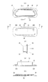
本発明の第1の実施の形態による取っ手10が図1乃至図7に示されており、この取っ手10は、図1及び図2に示すように、戸棚の戸の如き手で開閉する適宜の開閉物体Mの表側と裏側とにそれぞれ配置され、開閉物体Mの取付け孔MH(図2参照)内で相互に嵌合して結合すべき周壁22、32をそれぞれ含む表側部材20と裏側部材30とを備えている。
A
表側部材20は、開閉物体Mの表面に係合すべきフランジ24を有し、また裏側部材30は、開閉物体Mの裏面に係合し取付け孔MHを閉じるべき取付け板34を有する。
The
表側部材20と裏側部材30とは、図2に示すように、表側部材20の周壁22の外面が取付け孔MHの内面に係合するように表側部材20の周壁22の内面が裏側部材30の周壁の外面に係合するようにして取付け孔MH内で相互に嵌合して結合されている。裏側部材30の周壁32は、下端側(周壁32の開口側とは反対の側)に大周部32Lを有し、この大周部32Lは、表側部材20の周壁22とほぼ同じ外周寸法を有し、表側部材20の周壁22の下側開口端22Eは、裏側部材30の周壁32の大周部32Lに対面又は係合している。
As shown in FIG. 2, the
図面から解るように、表側部材20、裏側部材30は、四隅に丸みを付した横長のほぼ矩形の形態を有し、それに伴って周壁22、32も四隅に丸みを付した横長のほぼ矩形の形態を有する。
As can be seen from the drawing, the
図4から解るように、表側部材20の周壁22の長手方向の両端の一方側にねじ螺入部22Hを有し、裏側部材30の周壁32のへこみ部32Rであって取付け板34にねじ貫通孔34Hを有する。図示しないねじは、裏側部材30のねじ貫通孔34Hを貫通して表側部材20のねじ螺入部22Hにねじ込んで表側部材20と裏側部材30とを固定的に結合している。なお、ねじ貫通孔34Hは、ねじの頭部が入り込む拡大部分34HLを有する。
As can be seen from FIG. 4, there are screw threaded
本発明の取っ手10は、開閉物体Mの内外を通気する通気手段40を含み、この通気手段40は、表側部材20と裏側部材30とのそれぞれ周壁22、32の間で嵌合方向に延びる通気溝42から成っている。
The
図示の形態では、通気溝42は、表側部材20の周壁22の内面に横方向(表裏の部材20、30の嵌合方向と直交する方向)に間隔をあけて設けられている多数の縦に細長い溝部分42Pから成っている。図5(A)(B)から解るように、これらの細長い通気溝42は、矩形状の周壁22の横長辺部に沿って設けられており、従って通気溝42は、周壁22の短辺部を除く内周面の大部分(相当の長い距離)に亘って形成されることになり、大きな通気量を有することができる。
In the form shown in the figure, the
図2に示すように、通気溝42の下端(裏側の端部)42LOは、裏側部材30の周壁32の大周部32Lと取付け板34とに亘って形成された通気孔36に相対しており、従って通気溝42の下端42LOは、裏側部材30の取付け板34で開口していることになる。通気溝42の上端(表側の端部)42UOは、表側部材20の周壁22の上端(表側の端部)22Uで上向きに開口している。
As shown in FIG. 2, the lower end (back side end) 42 </ b> LO of the
表側部材20は、通気手段40の多数の通気溝42の上向き開口42UOを閉じることなく覆う開口覆い手段50を有する。図示の第1の実施の形態では、この開口覆い手段50は、表側部材20のフランジ24に被せられて通気溝42上向き開口42UOを覆う補助蓋52から成っている。
The
この補助蓋52は、図2に示すように、表側部材20のフランジ24の下面に係合する内向きフランジ52Fを有し、取っ手10の使用時には、この補助蓋52の内向きフランジ52Fは、表側部材20のフランジ24と開閉物体Mの取付け孔MHの周縁表面との間に挟まれる。
As shown in FIG. 2, the
補助蓋52も、四隅に丸みを付した横長のほぼ矩形の形態を有し、その上壁52Uは、周辺から中央に向けて斜め上向きに傾斜しており、その上縁から同様に四隅に丸みを付した矩形状の指差込み孔52Hを形成するように下向きに延びる内周壁54を有し、指差込み孔52Hに差し込んだ指をこの内周壁54に掛け止めて開閉物体Mを開閉するように取っ手10を操作する。上壁52Uは、図2及び図3(A)に示すように、相対する長辺部分で幅を異にしていて、幅広の上壁部分に指を差し込むようにしているが、相対する長辺部分の幅は同じにしてもよい。
The
本発明のこの第1の実施の形態による取っ手10は、図2に示すように、開閉物体Mの取付け孔MHに表側部材20の周壁22を圧入し、表側部材20の周壁22の内面に裏側部材30の周壁32を嵌入し、図示しないねじを裏側部材30のねじ貫通孔32Hに貫通し、表側部材20のねじ螺入部22Hに螺入して表裏の部材20、30を結合して両者を一体に組立てて形成される。補助蓋52は、予め、表側部材20のフランジ24に被せられており、従って表側部材20の周壁22を開閉物体Mの取付け孔MHに圧入すると、補助蓋52の内向きフランジ52Fは、開閉物体Mの取付け孔MHの周辺の表面と表側部材20のフランジ24との間に固定される。なお、図3(B)及び図5に示すように、表側部材20の周壁22の外面には適宜の間隔をあけてテーパ状のリブ22Rが設けられ、また裏側部材30の周壁32の大周部32Lの外面には同様のテーパ状のリブ32LRが設けられており、これらのリブ22R、32LRは、周壁22が取付け孔MHに圧入される際に取付け孔MHの内面に押し付けられて周壁22、32を堅固に取付け孔MHに取り付ける機能を有している。
As shown in FIG. 2, the
図2に示すように、開閉物体Mの外側の空気は、表側部材20の補助蓋52の指差込み孔52Hから表側部材20の周壁22の通気溝42、裏側部材30の通気孔36(即ち通気手段40)を経て開閉物体Mの内部に入り込み、また開閉物体Mの内部の空気は、裏側部材30の通気孔36、表側部材20の周壁22の通気溝42、補助蓋52の指差込み孔52Hを経て外部に放出され、従って、開閉物体Mの内外は、この通気手段40を介して通気される。
As shown in FIG. 2, the air outside the opening / closing object M flows from the
図示の形態では、周壁22の上端で外向きフランジ24とは反対側の部分に通気溝42の上端開口から斜め上向きに延びる傾斜開口42UCを形成する内向きフランジ25を有し、外気は、この内向きフランジ25内の傾斜開口42UC、上端開口42LOを介して通気溝42に連通しているが、この内向きフランジ25はなくてもよい。
In the form shown in the figure, the upper end of the
上記のように、通気手段40が表側部材20の周壁の内周に設けられて裏側部材30の取付け板32の通気孔36を介して裏側部材30の内側に連通している通気溝42から成っていると、通気溝42は、表側部材20の周壁22と裏側部材30の周壁32との間に位置し、従って周壁22、32の開口端側の通気溝42の端部は、表側部材20の周壁22の内面に位置する上に通気溝42の開口は上向きとなるため、特に、開口覆い手段50がなくても通気手段40による取っ手10の見栄えを悪くすることがないが、開口覆い手段50は、通気溝42の開口を隠して見栄えを一層向上することができる。
As described above, the ventilation means 40 is provided on the inner periphery of the peripheral wall of the
更に、通気溝42は、表側部材20の周壁22の内面に沿って設けられるので、従来の裏側部材の取付け板の板面を貫通して通気孔を設けるものに比べて、見栄えを悪くすることなく、空気通路の数(通気溝の数)を多くすることができ、通気量を増大することができる。
Furthermore, since the
なお、通気溝42は、表側部材20の周壁22の内面に代えて裏側部材30の周壁32の外面に設けてもよいし、表裏の部材20、30の周壁22、32の相対する面に半円形の形態で形成してもよく、これらの場合にも、上記と同様の効果を得ることができる。
The
また、図示の形態では、通気溝42は、垂直方向に細長い多数の溝部分42Pから成っているが、周壁面に沿って横長で幅広に形成された1つ又は少数の溝又は溝部分から成っていてもよく、この場合には、周壁22,32の開口端側の通気溝42の端部は、単純化して見栄えが一層向上する上に、通気量も一層増加するので有利である。
In the illustrated embodiment, the
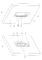
本発明の第2の実施の形態による取っ手10が図8乃至図13に示されている。この実施の形態による取っ手10、は、開口覆い手段50を除き図1乃至図7の実施の形態による取っ手10の構造と実質的に同じであり、同じ部分には同じ符号が付されている。
A
第2の実施の形態による取っ手10の開口覆い手段50は、補助蓋52を有しないで、図9、図10(A)、図12(A)及び図13(A)に示すように、表側部材20の周壁22の開口部に外向きフランジ24とは反対側に延びて通気溝42の上端開口42UOを覆う内向きフランジ(突出部)25から成っている。第2の実施の形態による周壁22の内向きフランジ25は、相対する横長辺の一方は大きく突出し、他方は小さく突出しており、従ってこれらの相対する横長辺の内向きフランジ25の突出幅が異なっているが、これらの突出幅は、同じであってもよい。
The opening covering means 50 of the
この第2の実施の形態では、表側部材20の周壁22の開口部が指差込み孔52Hを形成し、またこの大きく突出する内向きフランジ25が差し込まれた指を掛ける指掛け部を兼ねている。
In the second embodiment, the opening portion of the
第2の実施の形態による取っ手10も、通気通路の見栄え及び通気量に関し、第1の実施の形態による取っ手10と同様の効果を有する。
The
上記2つの実施例では、表側部材20は、フランジ24を有していてこのフランジ24が開閉物体Mの表面に係合しているため、このフランジ24の厚み分だけ取っ手10が突き出しているが、フランジ24がなくてもよく、この場合、表側部材20は、周壁22の内面から斜めに貫通して開閉物体Mの肉厚壁にねじ込む複数のねじによって開閉物体Mに固定してもよい。
In the above two embodiments, the
また、上記2つの実施例では、種々の家具等の抽斗、戸等の開閉物体Mに取り付けたが、例えば、種々の置台や置物の如き非開閉式物体の両側面に指を差し込んでこの物体を持ち上げるための取っ手として用いてもよい。 Further, in the above two embodiments, it is attached to an open / close object M such as various furniture drawers, doors, etc. For example, this object can be obtained by inserting a finger into both sides of a non-open / close type object such as various tables and figurines. It may be used as a handle for lifting.
本発明によれば、上記のように、通気手段が表裏の部材の周壁の相対する面の一方又は双方に跨って設けられて周壁の嵌合方向に沿って形成されている通気溝から成っているため、見栄えを良くすることができ、高い産業上の利用性を有する。 According to the present invention, as described above, the ventilation means includes the ventilation groove provided across one or both of the opposing surfaces of the peripheral walls of the front and back members and formed along the fitting direction of the peripheral walls. Therefore, it can be improved in appearance and has high industrial applicability.
M 開閉物体
MH 取付け孔
10 取っ手
20 表側部材
22 周壁
22E 下側開口端
22U 上端
22R リブ
24 外向きフランジ
25 内向きフランジ
30 裏側部材
32 周壁
32L 大周部
32R へこみ
34 取付け板
34H ねじ貫通孔
34HL 拡大部分
36 通気孔
40 通気手段
42 通気溝
42P 溝部分
42LO 通気溝の下端
42UO 通気溝の上端(表側の端部)
42UC 傾斜開口
50 開口覆い手段
52 補助蓋
52F 内向きフランジ
52U 上壁
52H 指差込み孔
54 内周壁
M Open / Close Object
42UC
Claims (6)
Priority Applications (1)
| Application Number | Priority Date | Filing Date | Title |
|---|---|---|---|
| JP2013171792A JP5778225B2 (en) | 2013-08-21 | 2013-08-21 | Handle |
Applications Claiming Priority (1)
| Application Number | Priority Date | Filing Date | Title |
|---|---|---|---|
| JP2013171792A JP5778225B2 (en) | 2013-08-21 | 2013-08-21 | Handle |
Publications (2)
| Publication Number | Publication Date |
|---|---|
| JP2015039508A JP2015039508A (en) | 2015-03-02 |
| JP5778225B2 true JP5778225B2 (en) | 2015-09-16 |
Family
ID=52694012
Family Applications (1)
| Application Number | Title | Priority Date | Filing Date |
|---|---|---|---|
| JP2013171792A Active JP5778225B2 (en) | 2013-08-21 | 2013-08-21 | Handle |
Country Status (1)
| Country | Link |
|---|---|
| JP (1) | JP5778225B2 (en) |
Families Citing this family (1)
| Publication number | Priority date | Publication date | Assignee | Title |
|---|---|---|---|---|
| KR101693368B1 (en) * | 2015-03-16 | 2017-01-17 | 주식회사 청암홈 | Insert type knob for both sliding door and hinged door |
-
2013
- 2013-08-21 JP JP2013171792A patent/JP5778225B2/en active Active
Also Published As
| Publication number | Publication date |
|---|---|
| JP2015039508A (en) | 2015-03-02 |
Similar Documents
| Publication | Publication Date | Title |
|---|---|---|
| US7530845B1 (en) | Connector EMI shielding structure | |
| JP5778225B2 (en) | Handle | |
| JP5277016B2 (en) | Air conditioner outdoor unit | |
| JP5578938B2 (en) | Face-to-face kitchen | |
| JP5420439B2 (en) | Entrance storage cabinet | |
| JP2006341002A (en) | Cover panel structure and kitchen | |
| JP6802237B2 (en) | Folding door | |
| JP2008253518A (en) | Cabinet | |
| JP2007103858A (en) | Cabinet rack | |
| KR200457939Y1 (en) | Attachable Door for Dog | |
| JP4780406B2 (en) | Embedded ceiling air conditioner | |
| KR100669013B1 (en) | Air Conditioner | |
| USD515314S1 (en) | Dual purpose toolbox | |
| JP2008075947A (en) | Ceiling embedded air conditioner | |
| JP2007085608A5 (en) | ||
| JP6026170B2 (en) | Door with ventilation function | |
| JP2014040974A (en) | Air conditioner | |
| JP7449818B2 (en) | Cover device for storage box | |
| JP4517084B2 (en) | Piping cover | |
| JPS6229861Y2 (en) | ||
| JP5348759B2 (en) | Residential distribution board | |
| CN211950230U (en) | Combined ventilation door | |
| JP5953814B2 (en) | Integrated air conditioner | |
| KR102509218B1 (en) | Rice cooker | |
| JP6643177B2 (en) | Frame member for combination cooking unit |
Legal Events
| Date | Code | Title | Description |
|---|---|---|---|
| A977 | Report on retrieval |
Free format text: JAPANESE INTERMEDIATE CODE: A971007 Effective date: 20150608 |
|
| TRDD | Decision of grant or rejection written | ||
| A01 | Written decision to grant a patent or to grant a registration (utility model) |
Free format text: JAPANESE INTERMEDIATE CODE: A01 Effective date: 20150707 |
|
| A61 | First payment of annual fees (during grant procedure) |
Free format text: JAPANESE INTERMEDIATE CODE: A61 Effective date: 20150708 |
|
| R150 | Certificate of patent (=grant) or registration of utility model |
Ref document number: 5778225 Country of ref document: JP Free format text: JAPANESE INTERMEDIATE CODE: R150 |